

Page 1

P1052234-001 Rev. A
August, 2012
QLn420-VC
Vehicle Cradle for QLn420 Printer
Page 2

Contents
Proprietary Statements....................................................3
Product Improvements.................................................................3
FCC Compliance Statement for QLn420-VC.................................3
Canadian Compliance Statement for QLn420-VC.........................3
Agency Approvals and Regulatory Information for QLn420-VC....3
Liability Disclaimer.......................................................................4
No Liability for Consequential Damage........................................4
Copyrights...................................................................................4
Document Conventions...................................................5
Introduction....................................................................7
Required for Installation..................................................8
Reference........................................................................8
Contents of the Package.................................................8
Installation......................................................................9
Introduction to Installation..........................................................9
Input Power Cable Completion......................................11
Using the Printer in the Vehicle Cradle..........................12
Printer Preparation....................................................................12
Printer Installation.....................................................................13
Printer Removal.........................................................................13
Loading Media...............................................................14
Printer Access...............................................................14
Vehicle Cradle Indicators...............................................15
Connections to a Terminal.............................................15
Installing the Mounting Arm..........................................16
Mounting Hardware...................................................................17
Vehicle Cradle Preparation.........................................................17
Input Power Completion............................................................17
Appendix A: Technical Specifications............................19
Technical Support..........................................................20
U.S. Only.....................................................................................20
All Others...................................................................................20
pg. 2 P1052234-001 Rev. A
Page 3

Proprietary Statements
This manual contains proprietary information of Zebra Technologies Corporation. It is intended solely
for the information and use of parties operating and maintaining the equipment described herein. Such
proprietary information may not be used, reproduced, or disclosed to any other parties for any other
purpose without the expressed written permission of Zebra Technologies Corporation.
Product Improvements
Since continuous product improvement is a policy of Zebra Technologies Corporation, all specifications
and signs are subject to change without notice.
FCC Compliance Statement for QLn420-VC
Class B digital device. Tested to comply with FCC standards.
WARNING: Exposure to Radio Frequency radiation with certain versions of the printer used with this
product. To conform to FCC RF exposure requirements this device shall be used in accordance with the
operating conditions and instructions listed in the printer’s User Guide. There are several radio options
available with the printer used in conjunction with this product. Additional regulatory information is
contained in the printer’s Users Guide in sections devoted to each radio option.
Changes or modifications to this unit not expressly approved by Zebra Technologies Corporation could
void the user’s authority to operate this equipment.
Canadian Compliance Statement for QLn420-VC
This Class B digital apparatus complies with Canadian ICES-003.
Cet appareil numérique de la classe B est conforme á la norme NMB-003 du Canada.
“IC:” before the equipment certification number signifies that the Industry Canada technical
specifications were met. It does not guarantee that the certified product will operate to the user’s
satisfaction.
Agency Approvals and Regulatory Information for QLn420-VC
• FCC part 15 Class B
• Canadian STD ICES-003 Class B
• EN55022 Class B European Electromagnetic Radiation Standard
• EN55024 European Immunity Standard
• EN60950-1 Safety Standard
• NOM (Mexico)
• C-Tick (Australia)
• VCCI (Japan)
• GOST-R (Russia)
• SABS (South Africa)
• SII (Israel)
• Ukrsepro (Urkaine)
• CE (EU/EFTA)
• E-Mark (EU/EFTA)
P1052234-001 Rev. A pg. 3
Page 4

Liability Disclaimer
In as much as every effort has been made to supply accurate information in this manual, Zebra
Technologies Corporation is not liable for any erroneous information or omissions. Zebra Technologies
Corporation reserves the right to correct any such errors and disclaims liability resulting therefrom.
No Liability for Consequential Damage
In no event shall Zebra Technologies Corporation or anyone else involved in the creation, production,
or delivery of the accompanying product (including hardware and software) be liable for any damages
whatsoever (including, without limitation, damages for loss of business profits, business interruption, loss of
business information, or other pecuniary loss) arising out of the use of or the results of use of or inability to
use such product, even if Zebra Technologies Corporation has been advised of the possibility of such
damages. Because some states do not allow the exclusion of liability for consequential or incidental
damages, the above limitation may not apply to you.
Copyrights
The copyrights in this manual and the label print engine described therein are owned by Zebra
Technologies Corporation. Unauthorized reproduction of this manual or the software in the label print engine
may result in imprisonment of up to one year and fines of up to $10,000 (17 U.S.C.506). Copyright violators
may be subject to civil liability.
ZebraLink and all product names and numbers are trademarks, and Zebra, the Zebra logo, ZPL, ZPL II,
Element Energy Equalizer Circuit, and E3 Circuit are registered trademarks of ZIH Corp. All rights reserved
worldwide.
CG Triumvirate is a trademark of AGFA Monotype Corporation. All rights reserved worldwide. CG
Triumviratetm font © AGFA Monotype Corporation. Intellifont® portion © AGFA Monotype Corporation.
All rights reserved worldwide. UFST is a registered trademark of AGFA Monotype Corporation. All rights
reserved worldwide.
All other brand names, product names, or trademarks belong to their respective holders.
©2012 ZIH Corp
pg. 4 P1052234-001 Rev. A
Page 5
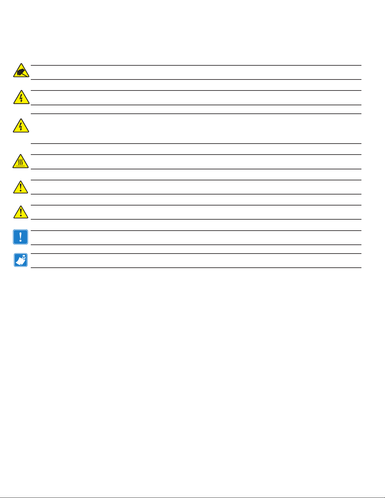
Document Conventions
The following conventions are used throughout this document to convey certain information:
Caution N Warns you of the potential for electrostatic discharge.
Caution N Warns you of a potential electric shock situation.
Warning N Indicates an imminently hazardous situation which, if not avoided, will result in death or serious injury. Before
you work on any equipment, be aware of the hazards involved with the electrical circuitry and be familiar with standard
practices for preventing accidents.
Caution N Warns you of a situation where excessive heat could cause a burn
Caution N Advises you that failure to take or avoid a specic action could result in physical harm to you.
Caution N Advises you that failure to take or avoid a specic action could result in physical harm to the hardware.
Important N Advises you of information that is essential to complete a task.
Note N Indicates neutral or positive information that emphasizes or supplements important points of the main text.
P1052234-001 Rev. A pg. 5
Page 6

Special Notices
Vehicle Installation Safety
Caution: Only trained and qualied personnel should be allowed to install, replace, or service this equipment.
Caution: DO NOT USE THE PRINTER WHILE DRIVING, as this may result in property damage or personal injury.
Zebra Technologies Corp. does not promote the use of these products except when parked or stationary, and
is not responsible for any loss resulting from the use or misuse of our products. Most importantly, we do not
want to see harm come to our customers or anyone else.
Caution: Do not install the Vehicle Cradle where it will be exposed to precipitation or excessive condensation.
Caution: Do not install the Vehicle Cradle on or near an airbag cover plate or within an airbag zone. Also, do not
install the Vehicle Cradle in a location that will aect vehicle safety or drivability.
Caution: The means of routing and securing the Power Input cable from the Vehicle Cradle through to the
vehicle power source is extremely important. Hazards associated with improper wiring can be severe. To
avoid unintentional contact between the wire and any sharp edges, provide the cable with proper bushings
and clamping where it passes through openings. If the wire is subjected to sharp
vibration, the wiring harness insulation can wear away, causing a short between the bare wire and the chassis.
This can start a re.
surfaces an
d excess engine
Caution: The vehicle charging circuit must neither undercharge nor overcharge the vehicle battery. Either fault
condition in the vehicle electrical system can cause a no-charge condition in the printer battery.
Warning: It is very important to ensure you make the correct cable to power source connections, because
electrical energy from a vehicle’s power system can harm equipment and people.
Caution: If you need to jump start your vehicle from another vehicle battery, disconnect the power cable running
to the Vehicle Cradle. Failure to do so can result in damage to your mobile printer and/or the Vehicle Cradle itself.
pg. 6 P1052234-001 Rev. A
Page 7

Introduction
NOTE: Zebra Technologies Corporation is not liable for personal injury or damage to any equipment caused
by the improper installation of this equipment to any power source.
This equipment should be installed in accordance with this installation guide and under the supervision of
properly trained and qualied personnel.
The QLn420-VC Vehicle Cradle allows use of the Zebra® QLn420 Printer in a vehicle. The Vehicle
Cradle receives power from a DC power adapter with an output of 12VDC. The DC power adapter plugs
into the cradle and the input is an unterminated cable which connects to the forklift/vehicle battery of 1560VDC.
The Vehicle Cradle is offered with a input power connection:
• An unterminated cable which must be wired into the vehicle’s power system (12 VDC Nom.)
An optional mounting arm provides the ability to locate the Printer and Vehicle Cradle in a variety of
positions and mounting locations to enhance its accessibility and ease of use.
The following instructions detail the installation and use of the QLn420-VC Vehicle Cradle. Following
these instructions closely will ensure safe, reliable performance of the QLn420 Printer when installed in
the Cradle.
The Printer runs off its own battery, which is monitored and charged by circuitry within the Printer.
• The user should always refer to the QLn Series Users Guide for complete information on using the
Printer.
• It is important that the vehicle’s electrical system function properly. The vehicle’s charging circuit
must work properly and vehicle-generated electrical “noise” must be minimized and within
specifications.
• The vehicle charging circuit must neither undercharge nor over-charge the vehicle battery.
Defective ignition wiring, damaged insulation, or faulty vehicle electrical components can cause
excess electrical noise severe enough to defeat the electrical filtering that is built into the Cradle
and the Printer.
P1052234-001 Rev. A pg. 7
Page 8

Figure 1: QLn420 VehicLe cradLe
Latch ReleaseButton.
Press to release Printer
from the Cradle
Power Indicator:
Always Green when
power is on
Required for Installation
• An electrical drill, 1/4”(6 mm) drill bit
• Common hand tools.
• #10-32 or 10-24 Bolts with self-locking (ESN) nuts and appropriate mounting hardware for securing
the Vehicle Cradle.
Note: Use of appropriate hardware used to secure the Vehicle Cradle to the vehicle is the responsibility of the installer
Reference
QLn420 printer User’s Guide
Contents of the Package
• The QLn420-VC Vehicle Cradle Assembly
• Power input DC power converter with unterminated cable (Zebra part number AK18913-003): input
15VDC-60VDC, 3.5A~0.9A
• QLn420-VC User Guide (in CDROM)
• Safety Sheet
pg. 8 P1052234-001 Rev. A
Page 9

Installation
137,7 mm
219,61 mm
Introduction to Installation
The QLn420-VC Vehicle Cradle allows you to mount a QLn420 Printer into virtually any vehicle with
an electrical system voltage 15-60VDC. The installation kit provided with the Cradle includes an input
power adapter which, when connected to the vehicle’s electrical system, provides power to run the
Printer and charge its battery.
The input power adapter (Zebra part number AK18913-003) is wired to the vehicle’s battery power
system indirectly through a power take-off point.
CAUTION: Under no circumstances should this equipment be attached directly to the vehicle’s battery
without a proper fuse.
Since each situation or equipment type may pose unique requirements, mounting hardware
selection and mechanical installation shall be the responsibility of the installer. Zebra recommends
using self-locking (ESN) nuts, bolts, and/or lock washers for installing the mount. The Cradle is secured
with #10-32 or #10-24 mounting hardware (4 places).
Note: Hardware used to secure the Vehicle Cradle to the vehicle is not supplied in the installation kit.
Your tasks are to:
Mechanically prepare and install the QLn420-VC Vehicle Cradle
Figure 2: VehicLe cradLe instaLLation dimensions
(5.42 “)
(8.64”)
(6.10”)
155 mm
67,7 mm
(2.66”)
66,2 mm
(2.60”)
(0.69”)
17,7 mm
30,16 mm
(1.18”)
Mounting Holes
200,6 mm
(7.89”)
38,1 mm
(1.5”)
Mounting Holes
Use 10-32 or 10-24 screws
P1052234-001 Rev. A pg. 9
Page 10

• Connect the power input cable of the DC power adapter from the vehicle’s electrical system.
It is important to leave a free zone around the printer to allow loading of paper and routine cleaning of
the print head.
If you are installing the optional mounting arm, remember the arm provides a considerable range of
movement for the Cradle and Printer. This allows adjustment to the best position for the operator. Extra
clearance should be provided for this movement if it is desired in the installation. Refer to pages 17-19 for
more information on installing the Cradle using the Mounting Arm.
Decide where you will mount the printer, and proceed with the following instructions.
CAUTION: Mount the Printer and Vehicle Cradle where it will not hit the operator in case of an accident.
Vehicle Cradle Preparation
Plan your installation with the above considerations in mind, and locate the Printer and Vehicle Cradle
so that the operator can easily load printing media, operate the printer’s controls and perform routine
maintenance such as cleaning the printhead. Follow these steps:
1. Select a location in the vehicle that will avoid personal contact in case of an accident.
2. Turn the Cradle upside down, and plug the output power cable of DC power adapter into the
bottom of the Cradle.
3. Route the power cable of the DC power adapter out of the Cradle. Make sure that the power cable
routing does not invite damage to the cable. To avoid unintentional contact between the wire and any
sharp edges, provide the cable with proper bushings and clamping where it passes through openings.
4. Route the input power cable of the DC power adptor to the vehicle’s power take-off point you will
be using.
Figure 3: dc Power adaPter cabLe routing
Velcro belt secures cable to
Vehicle Cradle
Plug the DC power adapter
cable into power input jack
pg. 10 P1052234-001 Rev. A
Page 11

Input Power Cable Completion
The DC power adapter terminates in bare wire and is intended for direct wiring into the vehicle electrical
system. The cable must be secured along its entire length and must not be allowed to hang loose, as
described in the section “Secure the Power Cable”, below.
• You must not cut the cable shorter. If there is extra length bundle the cable securely to eliminate
the excess.
CAUTION: There must be a fuse between the vehicle’s power source and the input power cable connection!
If you are not using the cable supplied with the Vehicle Cradle, selecting the size and rating of this fuse is
the installer’s responsibility.
• The installer must find the nearest practical connection point to the vehicle’s main battery
voltage. Consult the vehicle manufacturer or a dealer to determine the best power connection
location. Note that the vehicle wiring leading to the connection point must be at least 18 AWG.
Note also that many vehicles use SAE wiring gage, which is different from AWG.
Prepare the Cable Ends:
NOTE: Actual cable termination used must be compatible with the power source. The following is a guideline.
1. Strip 1/4” (6 mm) of insulation from the BLACK wire.
2. Securely crimp the supplied 3/8” terminal ring onto the BLACK wire.
3. Strip 1/4” (6 mm) of insulation from the RED wire.
4. Securely crimp the supplied 3/8” terminal ring onto the RED wire.
Connect Cable to the Power Source
1. Ensure that cable terminals are well connected to the cable.
2. Connect black cable ground (-) terminal to vehicle ground location.
3. Connect red cable power (+) terminal to vehicle power source.
Secure the Power Cable
Make sure that the cable routing does not interfere with other equipment or vehicle controls. Insure
that the cable routing protects the cable from damage during vehicle use.
P1052234-001 Rev. A pg. 11
Page 12

Using the Printer in the Vehicle Cradle
Printer Preparation
Prepare the printer for docking onto the Vehicle Cradle by doing the following:
It is strongly recommended as a safety precaution that the adjustable shoulder strap or hand strap be
removed prior to docking the printer. This precaution will ensure the strap will not interfere with proper
operation.
• Always install the battery prior to placing the printer in the cradle.
• Remove and retain the docking contacts cover located on the bottom of the printer that covers
the docking contacts. Also retain the two screws which secure the docking connector cover to
the printer.
Docking Contacts
Docking Contacts
Cover
Figure 4: docking contacts and contacts coVer
• If necessary, clean any residue from the docking contacts using a Zebra cleaning pen or a
cotton swab with 70% Isopropyl alcohol. This should also be done over time on an as-needed
basis.
pg. 12 P1052234-001 Rev. A
Page 13

Printer Installation
The QLn420 printer can now be installed in the Vehicle Cradle.
Figure 5: instaLLing the Printer in the VehicLe cradLe
Press Button to Move the
Latches Toward the Rear
of the Cradle
Latches
• Align the rear of the printer with the two pegs in the cradle.
• Place the Printer into the Cradle firmly in place.
• Release the Release Button and verify the latches are locked with printer firmly.
• Turn the vehicle’s power source for the Cradle on, and verify that the charger indicator on
printer LCD and power indicator light on the Cradle’s side panel are lit.
• Turn the printer on and print a configuration label to verify that the printer is functioning
properly. Refer to the QLN Seires User’s Guide for instructions on printing a configuration label.
Printer Removal
Remove the printer from the Vehicle Cradle by doing the following:
• Turn the Printer off.
• If the Printer is directly connected to a communications cable, unplug and remove the cable
from the Printer.
• Press the latch release button on the Vehicle Cradle and pivot the Printer out of the Cradle.
• If you will be using the Printer out of the Vehicle Cradle for a prolonged period, replace the
Docking Connector Cover on the Printer.
P1052234-001 Rev. A pg. 13
Page 14

Loading Media
Using the Printer’s Internal Media Supply
If you are using the Printer’s internal media compartment, follow the loading procedures found in
the QLn Series User’s Guide.
Using an External Media Supply
If the printer’s media supply is from an external supply, typically fanfold media, you must make
provisions for a media bin to be positioned to allow media to enter the printer through either the
bottom or the back of the Vehicle Cradle. If the Cradle is mounted against a vertical surface there is a
slot and guiding features in the base to insure the media will feed properly into the printer.
If you are using an external media supply follow these steps to load media:
1. Open the QLn420’s media supply compartment.
2. Load the media from the external supply through the feed slots in the bottom of the Cradle and the
Printer and past the printhead. Note that if you are using 4 inch (10.16 cm) wide external media, you
can install the Fanfold Spacer (Zebra p/n BA16625-1) between the printer’s media supports to keep
them from binding on the edges of the media.
3. Close and latch the media compartment.
NOTE: Your printer must be congured with the External Media option to use an external media supply.
If using an external media supply bin, ensure no extra items are suspended from either the Printer or the
Vehicle Cradle.
Printer Access
The media compartment and operator controls can be reached while the printer is secured in the
Vehicle Cradle.
If you need to remove the printer for servicing follow the removal procedure detailed above in the
Printer Installation and Removal section.
pg. 14 P1052234-001 Rev. A
Page 15

Vehicle Cradle Indicators
The Vehicle Cradle has one LED indicator on the panel as shown in Figure 1. The power LED is
green when power is supplied to the cradle.
Charging status will be displayed on the printer LCD.
It should be noted that the battery only charges between 0o to 40oC while in the cradle.
NOTE: If the charge indicator on the Printer LCD does not indicate charging when the printer is installed,
it may be the result of one of two possible conditions:
1) The printer is not seated properly in the cradle. Unlatch and redock the printer into the cradle. Observe
if LCD indicates charging.
2) If re-docking the printer does not cause the LCD to indicate charging it is because the printer has
entered a 30 minute prequalication process. At the end of this process the printer will either (1)
commence charging or (2) not commence charging in which case there is a battery error.
Connections to a Terminal
Communications with a Terminal
If you are also installing a terminal in the vehicle, consult the terminal manufacturer’s literature
for installation instructions. If the terminal and Printer will communicate using either an RS232 or
USB cable, use shielded cables and keep their length as short as possible. Ensure the routing of the
cable does not invite damage to the cable or interfere with the control or use of the vehicle.
Consult the factory for information on the various I/O data cables offered by Zebra for use with a
variety of widely used terminals.
NOTE: This unit was tested with shielded cables on the peripheral devices. Shielded cables must be
used with the unit to insure compliance.
If the terminal and the Printer will communicate via an RF link, it is the installer’s responsibility to
test the strength and reliability of such a link prior to final installation.
P1052234-001 Rev. A pg. 15
Page 16

Power Connections to a Terminal
If you are also installing a terminal in the vehicle, you must run two separate cables from the vehicle power
source: one to the printer and one to the terminal.
Warning: Do not attempt to power both devices from the same power cable.
The terminal power cable must be either supplied by the terminal manufacturer or fabricated by the installer.
It is the installer’s responsibility to determine the suitability of running a terminal from the vehicle’s battery.
NOTES: This Installation Guide does not cover the installation of any terminal used in conjunction with the
QLn420 Printer or Vehicle Cradle.
Zebra Technologies Corporation is not liable for personal injury or damage to equipment caused by improper
installation to any power source.
Installing the Mounting Arm
Description
An optional mounting arm (Zebra p/n P1010338) is offered for use with the Vehicle Cradle which allows
a more versatile method of positioning the QLn420 Printer. It consists of an arm with a ball and socket
joint at either end, which in turn are terminated with a mounting flange. One flange is secured to the
Cradle by the four mounting holes provided on the bottom plate, and the other is secured to the desired
mounting surface. A clamp on the arm locks the Cradle in the desired position.
Installation
Caution: Mount the Printer and Vehicle Cradle where it will not hit the operator in case of an accident.
Warning: Do not connect the input power cable to the Vehicle Cradle until the Cradle and Mounting Arm
installation has been completed.
For ease of installation, the Arm can be disassembled by loosening the clamp enough to remove the
two ball and socket flanged ends. These end flanges can then be easily secured to the Vehicle Cradle and
the desired mounting surface. Then the arm can be slipped over the two ends and the clamp tightened
to secure the Cradle in position.
When installing the mounting arm, remember that the arm provides a considerable range of
movement for the Vehicle Cradle and Printer. Extra clearance should be provided for this movement if it
is desired in the installation.
pg. 16 P1052234-001 Rev. A
Page 17

Mounting Hardware
Mounting hardware is supplied with the Mounting Arm Kit. The #10-32 or #10-24 screws should be
used to secure one end of the arm to the bottom of the Vehicle Cradle. The #10-24 x 3/4” screws and
associated hardware may be used to secure the other end of the arm to the desired mounting surface.
Vehicle Cradle Preparation
Refer to the section on Vehicle Cradle Preparation earlier in this manual for more specific instructions
and illustrations on securing the power cable to the Cradle. Locate the Printer and Cradle so the
operator can easily load printing media when installed with the Mounting Arm, operate the printer’s
controls and perform routine maintenance such as cleaning the printhead. Follow these steps:
1. Select a location in the vehicle that will avoid personal contact in case of an accident.
2. Turn the Cradle upside down and plug the input power cable into the bottom of the Cradle.
• Route the input power cable out of the Cradle. Note that it can be routed out either side of the
Cradle and that there are retaining features in the Cradle to keep the cable in place. Refer to Figure
3.
• Be sure to leave enough slack in the power cable to allow the Mounting Arm to pivot freely
without putting strain on the power connections.
• Make sure that the input power cable routing does not invite damage to the cable when the
Vehicle Cradle is pivoted.
3. Once the cable routing has been determined, secure it to the Vehicle Cradle with the Velcro belt
which is attached to the Vehicle Cradle (see Fig. 3).
4. Secure one of the mounting flanges from the movable arm to the bottom of the Vehicle Cradle
with the four (4) #10-32 or #10-24 screws supplied with the Mounting Arm.
5. Secure the other mounting flange on the movable arm to the desired mounting surface. You can
use the #10-24 x 3/4” screws and associated hardware supplied in the Mounting Arm Kit or use
other hardware as the mounting conditions dictate.
Input Power Completion
Route the input power cable of the DC power adapter per the earlier section in this Guide: “Input
Power Cable Completion” on Page 11.
P1052234-001 Rev. A pg. 17
Page 18

Figure 6: oPtionaL mounting arm dimensions
7. 35 ”
[187 mm]
2.43” [62 mm}
1.19” [30 mm}
1.5 0” [38 mm}
Figure 7: securing the VehicLe cradLe to the mounting arm
R .91” [23 mm}
Use #10 (1” long srews)
hardware supplied with kit
to secure to Cradle
Vehicle Cradle
Tightening Clamp
Use #10 (3/4” small srews)
hardware supplied with kit to
secure to mounting surface
pg. 18 P1052234-001 Rev. A
Page 19

Appendix A: Technical Specifications
Physical
• Height: 3.05 in (77.5 mm)
• Length: 8.66 in (220 mm)
• Width: 7.9 in (201 mm)
• Weight (cradle only): 1.06 lbs (0.48 kg)
• Weight (cradle, DC adapter): 1.76 lbs (0.8 kg)
Environmental
• Operating Temp: 32°F (0°C) to 104°F (40°C)
• Storage Temp: -13°F (-25°C) to 158°F (65°C)
• Humidity: 10% to 90% non-condensing
• Drop: 4 ft (1.2M) to concrete (without printer)
• Vibration: Per Mil-Std-810
DC Adapter:
• Input: 15VDC-60VDC, 3.5A~0.9A
P1052234-001 Rev. A pg. 19
Page 20

Technical Support
Zebra Technologies Corporation
U.S. Only
Zebra maintains a help line for questions involving installation and use of the QLn420-VC.
Please have as much information as possible regarding your particular application ready when
you call to enable the technical support personnel to help you. The number in the U.S. is
(800)-423-0442 and is open Monday through Friday from 8:00 am to 4:30 P.M. E.S.T.
All Others
For technical support, please contact your local Zebra sales representative listed below:
Zebra Technologies Europe Limited
Dukes Meadow
Millboard Road
Bourne End
Buckinghamshire SL8 5XF, UK
T: +44 (0)1628 556000
F: +44 (0)1628 556001
Zebra Technologies Asia Pacic, LLC
120 Robinson Road
#06-01 Parakou Building
Singapore 068913
T: +65 6858 0722
F: +65 6885 0838
Zebra Technologies
Latin America Sales Oce
9800 NW 41 Street
Suite 220
Doral, Florida 33178 USA
T: +1.305.558.8470
F: +1.305.558.8485
475 Half Day Road, Suite 500
Lincolnshire, IL 60069 USA
T: +1 847.634.6700 or +1 800.423.0442
pg. 20 P1052234-001 Rev. A
 Loading...