

Page 1

Document Number: 30580-000-002
PTC-2124
Windows CE Software
Guide
Page 2

Chapter 3 Configuring TN-3270/5250
Page 3

PTC-2124
INDOWS CE Software Guide
W
Document Number: 30580-000-002
Release Date: November 2000
Page 4

Chapter 3 Configuring TN-3270/5250
Symbol is a registered trademark of Symbol Technologies, In c.
Windows 95 and Microsoft are r egistered trademarks
of the Microsoft Corporation.
All other product or trade references appearing in this manual are registered
trademarks of their respective owners.
The information in this manual is subjectto change without notice.
Symbol Technologies shall not be liable for technical or editorial omissions or
mistakes in this manual. Nor shall it be liable for in cidental or consequential
damages resulting from the use of the information contained in this manual.
This manual is copyrighted. No part of this manual may be photocopied or
reproduced in any form without the prior written consent of Symbol.
Technical Writer: Norm Walters
© Copyright 2000 Symbol Technologies, Inc.
All rights reserved.
Page 5

This Guide’s Purposeand Scope
Introduction
This Guide’s Purpose and Scope
This manual was written by the Symbol Technical
Publications Group. This group is tasked with
providing technical documentation for the Symbol
PTC-2124 product line that uses the Microsoft®
Windows CE® Operating System. Ev ery effort has
been made to provide accurate and concise information
to you, our customer.
The PTC-2124 Windows CE Guide provides
information that allows the use r to set up and use the
PTC-2124. This manual is meant to provide
information on the various components of this
product, including
• General regulations,
• Overview of the PTC-2124,
• Maintenance and trouble shooting,
• Available accessories.
This manual, h owever, does not provide instructions
on how to perform t he tasks specific to your job within
your organization. For job-specific information, refer to
the instructions provided b y your organization.
PTC-2124 Windows CE Guide i
Page 6

Chapter 3 Configuring TN-3270/5250
Contacting Symbol’s Support Center
Symbol’s Support Center may be contacted to obtain
help in resolving any PTC-21 24 system problem that
you may experience.
If you have a problem running your unit or using your
equipment, contact your facility’s technical or system
support. If there is a problem with the equipment, the
system support will contact the Symbol Support
Center at 1-800-653-5350.
For additional information on Symbol’s products and
services, please visit our website at
www.symbol.com.
ii PTC-2124 Windows CE Guide
Page 7

Table of Contents
About this Manual........................................................................... i
Contacting Symbol's Customer Support Center............................ i
Purpose a nd S cope of this Manual................................................. ii
PTC-2124 O verview ........................................................................ 1
Boot Loader...................................................................................... 1
Operating System ............................................................................ 2
Functional Overview....................................................................... 3
Applications.................................................................................. 3
Shell.............................................................................................. 4
Core System API.......................................................................... 4
Kernel........................................................................................... 4
OEM Adaptation Layer (OAL).................................................... 4
Other Software Components .......................................................... 5
Power Management..................................................................... 5
SoftwareDevelopment Kits......................................................... 5
PTC-2124 U nit Configurations ..................................................... 6
Radio Options.................................................................................. 7
Batch............................................................................................. 7
LAN Radio Ready......................................................................... 7
WAN Radio Factory Installed..................................................... 7
Memory............................................................................................ 8
RAM.............................................................................................. 8
ROM .............................................................................................. 8
Storage Options............................................................................... 8
ATA............................................................................................... 8
SRAM............................................................................................ 8
Compact Flash.............................................................................. 9
PCMCIA Slots.................................................................................. 9
Display............................................................................................. 10
IrDA ................................................................................................. 10
Ethernet........................................................................................... 11
DCD Devices.................................................................................... 11
Scanners....................................................................................... 11
PTC-2124 Windows CE Software Guide iii
Page 8

PTC-2124 Assignments .................................................................. 12
Hardware Interrupts....................................................................... 13
InterruptTable............................................................................. 13
COM Port Assignments .................................................................. 14
Rebooting/Resetting the PTC-2124................................................ 1 5
Rebooting ...................................................................................... 1 5
Resetting....................................................................................... 1 5
Loading Windows CE ..................................................................... 16
Requirements .................................................................................. 16
Required Files .............................................................................. 16
Windows CE Image...................................................................... 1 6
Windows CE Boot Loader............................................................ 16
Genesis Creation Utility.............................................................. 16
Copying and Booting the Operating System ................................. 17
Loading the Boot Loader (Creating the Genesis Card).............. 17
Copying the Windows CE OS Image........................................... 22
Genesis Utility ......................................................... .................... 24
Updating Earlier Builds of W indows CE.................................... 25
Connecting to a Host....................................................................... 26
Using S erial or IrDA.................................................................... 26
Network Setup ............................................................................. 27
LAN Radio Installation................................................................... 30
Test t he R adio .............................................................................. 31
Uninstall Aironet driver.............................................................. 31
Windows CE Recovery................................................................... 32
Overview.......................................................................................... 32
Hardware Requirements................................................................. 33
Software Requirements................................................................... 34
Preparations.................................................................................... 34
BIOS Genesis Card...................................................................... 34
Boot Disk...................................................................................... 35
PCMCIA ATA Card (Optional).................................................... 36
Recovery Procedure......................................................................... 37
Three (3) Card Process................................................................. 38
iv PTC-2124 Windows CESoftware Guide
Page 9

Power Management........................................................................ 39
Windows CE Power Management.................................................. 39
AMD Elan SC400 Power Management .......................................... 40
APM And Windows CE ................................................................... 42
Symbol Windows CE Power Management..................................... 42
Online And Offline Configuration............................................... 4 4
Drivers And Th read Activities .................................................... 45
Power Management Initialization .............................................. 46
Magic Packet Mode ...................................................................... 48
SC 400 Power Control..................................................................... 49
Cradle Information......................................................................... 50
Cradle O verview.............................................................................. 5 0
PTC-2124 Cradle Interactio n ......................................................... 51
Cradle Serial Interface ................................................................ 52
DTR and RTS Latching ............................................................... 54
Ring Indicator .............................................................................. 54
DB-9 Serial Connector Pinout..................................................... 55
Ethernet Port ............................................................................... 55
KeyboardPort .............................................................................. 56
CRADMON.EXE ............................................................................. 57
The Cradmon Dialog Box............................................................. 58
PCMCIA............................................................................................. 61
The PCMCIA Card.......................................................................... 61
Formatting an SRAM or ATA Card ............................................... 63
DCDWedge........................................................................................ 64
System Requirements..................................................................... 64
DCDWEDGE Operation.................................................................. 65
Overview of D CD.......................................................................... 65
Data Formatting.......................................................................... 66
User Interface............................................................................... 67
DCDWEDGE Configuration Options.......................................... 68
PTC-2124 Windows CE Software Guide v
Page 10

Running DCDWEDGE.................................................................... 69
Setting up DCDWEDGE.............................................................. 69
Using D CDWEDGE ..................................................................... 70
DCDWEDGE Dialog Box................................................................ 71
Device Page .................................................................................. 72
DCD Page..................................................................................... 73
Wedge Page .................................................................................. 74
Sounds Page ................................................................................. 80
Activation Page ............................................................................ 81
Miscellaneous Page...................................................................... 82
Wedge Configuration Dialog Box ................................................... 84
Other DCDWEDGE Popup Menu Items........................................ 85
Driver Su pport ................................................................................ 86
Ethernet........................................................................................... 86
Display............................................................................................. 86
Keyboard.......................................................................................... 86
PCMCIA ........................................................................................... 87
Battery............................................................................................. 87
Power Management......................................................................... 88
Cradle............................................................................................... 88
Touch Panel..................................................................................... 89
Serial IrDA ...................................................................................... 9 0
DCDAPI........................................................................................... 90
SE1200 Scanner.............................................................................. 91
Cisco/Aironet Windows CE D river ................................................. 92
Cisco/Aironet Windows CE Driver Installation.......................... 92
Configurator Installation............................................................. 93
Control Panel Applets.................................................................... 94
Symbol Applet ................................................................................. 95
Buttons Page ................................................................................ 96
WAN Page .................................................................................... 99
IRDA Page.................................................................................... 100
ETHERNET Page ........................................................................ 101
Cradle Con figuration Applet .......................................................... 102
vi PTC-2124 Windows CESoftware Guide
Page 11

Power Applet ................................................................................... 103
The Battery Page ......................................................................... 103
The Offline Page........................................................................... 104
The Online Page........................................................................... 105
ActiveSync........................................................................................ 106
Requirements .................................................................................. 106
Establishing a S erial Connection Using ActiveSync..................... 1 07
Breaking the ActiveSync Connection............................................. 108
Miscellaneous Utilities .................................................................. 109
Registry View .................................................................................. 110
Save Registry................................................................................... 110
Time/Date........................................................................................ 110
Version............................................................................................. 111
TFlashsc.exe.................................................................................... 111
CE.ini............................................................................................... 112
Default.......................................................................................... 112
CopyFiles...................................................................................... 114
DeleteFiles.................................................................................... 115
AddReg.......................................................................................... 116
DeleteReg...................................................................................... 118
Shortcuts ...................................................................................... 119
DeleteShortcuts............................................................................ 120
Accessories....................................................................................... 121
References ........................................................................................ 122
PTC-2124 Windows CE Software Guide vii
Page 12

viii PTC-2124 Windows CE Software Guide
Page 13

Boot Loader
PTC-2124 Overview
The PTC-2124 is a rugged AMD™SC400
processor-powered, pen-based Portable
Tele-transaction Computer (PTC). It couples standard
PC tec hnology with Symbol’s expertise in data
collection and radio technology to provide a flexible,
high-performance portable system.
This section of the manual provides a basic overview
of the PTC-2124’s software environment, including
brief discussions of the following:
• the boot loader,
• the operating system and applications,
•thesoftwarekernel,
• power management,
• software development kits (SDKs), and
• unit configurations.
Boot Loader
The boot loader is a piece of software that replaces the
BIOS of a DOS-based system. The boot loader’s
primary functions are to load a Windows CE
into the RAM of a target unit and then boot the unit
in the Windows C E Operating system.
The Boot Loader module resides i n XIP FLASH
memory in the upper 64 KB where the SC400’s power
on/hard r eset vector exists. It is the first code
executed w hen the device is turned on from a
complete power down state.
PTC-2124 Windows CE Software Guide 1
™
image
Page 14

Chapter 3 Configuring TN-3270/5250
ThemodulefirstperformssetupoftheSC400DRAM
controller. The Symbol device has 4 MB of DRAM in
Bank 0 and 16 MB (or 32 MB, or 64 MB) of expansion
DRAM in Bank 1. Bank 0 is dis abled with the 64 MB
expansion. After setup of the DRAM controller, the
module sets up the stack and then copies itself into
RAM, executing out of RAM to allow for faster
execution.
Once in RAM, the Boot Loader module initializes the
debug serial port (19200, 8, N, 1) and attempts to load
the CE registry and CE image from the Compact
Flash memory card into RAM. After successfully
loading to RAM, the Windows CE operating system is
launched.
Operating System
Windows CE is a real time operating system that was
developed specifically for use in embedded devices. In
an effort to meet the portability and modularity need s
of the embedded market, Windows CE was designed
to be highly componentized and configurable. While
Microsoft
Windows CE system, some components come from
other sources, such as Independent Software Vendors
(ISV) and O riginal Equipment Manufacturers (OEM).
The sections below describe the interaction of these
component s ources.
™
supplies much of the components for a
Note: This guide was written to reflect Windows CE
version2.12.
2 PTC-2124Windows CESoftware Guide
Page 15

Functional Overview
Functional Overview
The follo wing table illustrates the Windows CE
software architecture, consisting of five major
software levels sitting above the hardware:
• Applications,
•Shell,
•CoreSystemAPI,
•Kernel,
• OEM Adaptation Layer (OAL ),
•Hardware.
Architecture Level Source
Applications ISV
Shell Microsoft
Core System API Microsoft
Kernel Microsoft
OAL OEM (Symbol)
Hardware OEM (Symbol)
Applications
The application is the highest software layer and
provides c ontrolling software programs for the unit.
These are provided by Independent Software Vendors.
PTC-2124 Windows CE Software Guide 3
Page 16

Chapter 3 Configuring TN-3270/5250
Shell
The shell is the outer layer of the operating system
that allows users and application programs to interact
effectively with the core operating system. Microsoft
provides shell components that allow developers to
build a customized shell to meet their needs. The shell
used on the Symbol SC400-based devices is the
standard Microsoft shell.
Core System API
The Core System API provides a mechanism through
which ap plications can access the operating system.
This includes a mechanism to transfer API calls to the
GWES module and supports functions such as local
heap and memory allo cation.
Kernel
The software kernel is the central component that
implements the core functionality of Windows CE.
The softwarekernel is a simple program loader that is
used to reprogram the PTC-2124 Flash PROM
memory areas.
OEM Adaptation Layer (OAL)
The OE M Adaptation Layer serves as the interface
between the software kernel and the hardware. It
does this through a set of routines that provide
functionality such as platf orm initialization, interrupt
service routines, profiling, interval timer debugging,
real-time clock, interru pt enable/di sable, etc.
4 PTC-2124Windows CESoftware Guide
Page 17

Other Software Components
Other Software Components
Power Management
Power management is a necessityfor battery-operated
devices such as the PTC-2124. The unit is designed to
incorporate battery-saving p ower management
functionsdirectlyintothe unit hardware and software
architecture. The platform hardware incorporates
features t hat allow most internal elements to be
slowed down or deactivated. Together, the hardware
and software constantly monitor system activity and
implementpower management activity states that are
used for power management functions.
Software Development Kits
Symbol provides application development tools in the
form of Software Development Kits (SDKs) to help
developers design application programs for the SC400
product family. The SDK is a collection of run-time
librariesand DLLs that assist in the development of C
and C++ programs for the PTC-2124. The
Windows CE Toolkit (for Maxall builds) can be used to
develop software if no PTC-2124 or Symbol specific
functionality is required. Th e Symbol SC400 SDK
provides functions in addition to the Windows CE
Toolkit.
PTC-2124 Windows CE Software Guide 5
Page 18

Chapter 3 Configuring TN-3270/5250
The PTC-2124 Windows CE unit is available in a wide
variety of configurations.
This section will cover the configuration options for
the following devices:
• Radio,
• RAM,
• ROM,
• Storage,
• PCMCIA Slots,
• Displays,
• IrDA,
PTC-2124 Unit Configurations
• Ethernet,
• DCD Devices.
6 PTC-2124Windows CESoftware Guide
Page 19

Radio Options
Radio Options
Batch
A batch unit does not have an antenna c able
integrated in the unit. It is still possible to install a
radio in the unit by way of the user accessible
PCMCIA slot 0. However, an external antenna must
be attached to the radio. Either of the PCMCIA slots
may be used for a radio c ard.
LAN Radio Ready
The radio ready unit has an RSMA antenna cable
integratedintotheunit.Theendofthecableroutes
through the unit to the externally accessible PCMCIA
slot door. A radio can be installed into PCMCIA slot 0
(slot closest from the unit’sdisplay).
WAN Radio Factory Installed
When ordered with a WAN radio such as a DataTac or
Mobitex network radio, the radio mo dule is installed
internally in the unit. Because these radio types are
not PCMCIA form factor, they require additional
spacein the unit. The unit thereforehas a deeper
backshell than non W AN radio equipped units.
PTC-2124 Windows CE Software Guide 7
Page 20

Chapter 3 Configuring TN-3270/5250
Memory
RAM
The PTC-2124 has RAM configurations of 20, 36, or
64 MB on the C PU board. When the 16- and 32- MB
memory modules are added, the 4 MB is included. The
64-MBconfigurationactually contains68 MB of RAM,
but the SC400 is able to address only 64 MB and the
4 MB on the CPU board is disabled.
ROM
The PTC-2124 comes with 512 KB of ROM.
Storage Options
ATA
The PTC -2124 supports ATA drives, both solid state
and rotating. ATA Type II cards can be applied to
either of the user accessible PCMCIA slots. Symbol
offers factory installed card options in a variety of
storage capacities. There is a facto ry installed
restraining bar that prohibits removal of the ATA
card when installed in slot 1.
The rotating AT A disks (any Type III) are installed in
PCMCIA slot 1 (farthest from the display).
SRAM
The PTC-2124 also supports SRAM (static RAM)
cards. Generally, these cards are used for special
purposes like reloadin g the ROM images (Genesis
procedure) or booting the unit, r ather than data
storage because the capacities are relatively lo w.
However,thesecardsmayalsobeusedbythe
application for data storage.
8 PTC-2124Windows CESoftware Guide
Page 21

PCMCIA Slots
Compact Flash
The PTC-2124 has an internal Compact Flash ad ap ter
which is a standard 50 pin port that supports a
variety of Compact Flash module sizes. (20 MB is the
minimum required to run Windows CE.)
PCMCIA Slots
The PTC-2124 has two PCMCIA slots that are
user-accessible. These external slots are controlled by
an Intel PCMCIA controller.
Slot 0
This is the card slot closest to the display.
Slot 1
This is the card slot farthest fro m the display.
PTC-2124 Windows CE Software Guide 9
Page 22

Chapter 3 Configuring TN-3270/5250
Display
The PTC-2124 is designed with a 4.7" (11.9 cm)
diagonal ¼ VGA screen. The standard monochrome
transflective LCD display offers 320 x 240 pixel
resolution, 64 levels of gray, and an EL backlight. A
scratch- and impact-resistant touch digitizer protects
the display.
The PTC-2124 includes a transparent, resistive-touch
digitizer mounted above the LCD display. The
digitizer is designed to support both stylus and finger
activation and incorporates a minimal amount of
"palm rejection" to help minimize hand contact. It also
uses transparent ma terial and will not interfere with
the LCD display.
Note: Some windows may appear t oo large
to completely fit into the viewable are
of the ¼ VGA display. To work
around this, tap on the title bar
portion of the window and drag into
the viewable area.
IrDA
The PTC-2124 supports an IrDA I/O port loc a ted on
the right side of the unit that pr ovides an optical
serial communication interface. The IrDA
communication port uses an infrared (IR) light beam
to support a half-duplex, point-to-point
communication link with a peripheral device.
10 PTC-2124 Windows CE Software Guide
Page 23

Ethernet
Ethernet
The PTC-2124 supports Ethernet communications
using a full 16-bit controller to provide a high-speed
Ethernet interface via the cradle c ontacts for transmit
and receive operation at 10 Mbps.
DCD Devices
The PTC-2124 supports Symbol’s Data Collection
Device (DCD) architecture. This architecture allows
applications to obtain data from a variety of data
input devices without requiring that device-specific
code be written. Devices with DCD-compliant drivers
are sometimes referred to as DCD Devices.
Scanners
The PTC-2124 supports an optional laser scanner
module. Using an attached laser scanner, the unit can
be progra mmed to automatically recognize, read, and
discriminate between up to six 1D barcode types. F or
instruction s on using a laser scanner module, refer to
the PTC-2124 User’s Guide.
PTC-2124 Windows CE Software Guide 11
Page 24

Chapter 3 Configuring TN-3270/5250
This section provides information on the following
PTC-2124 com p o ne nts:
• Hardware Interrupts,
• COM Port Assignments.
PTC-2124 Assignments
12 PTC-2124 Windows CE Software Guide
Page 25

Hardware Interrupts
Hardware Interrupts
Knowledge of hardware interrupt assignments will be
useful for making system configuration decisions.
Interrupt Table
PTC-2124 hardware is assigned to the following
interrupts (IRQs):
Hardware Interrupt Device Usage
IRQ 0 (SC400 Internal) Programmable Interval Timer
IRQ 1 (SC400 PIRQ 5) Keyboard
IRQ 2 (SC400 Internal) Reserved
IRQ 3 (SC400 PIRQ 6) COM 2 and COM4 on T130 ASIC
IRQ 4 (SC400 Internal) IrDA
IRQ 5 (SC400 PIRQ 3) Audio
IRQ 6 (SC400 Internal) SC400 PCMCIA Controll er
IRQ 8 (SC400 Internal) Real Tim e Clock
IRQ 9 (SC400 PIRQ 2) External PCMCIA Controller
IRQ 10 (SC400 PIRQ 7) Ethernet
IRQ 11 (SC400 Internal) SC400 PCMCIA Controller
IRQ 12 (SC400 PIRQ 4) Touch
IRQ 13 (SC400 PIRQ 1) T130 ASIC
IRQ 14 (SC400 PIRQ 0) Compact FLASH Memory Card
PTC-2124 Windows CE Software Guide 13
Page 26

Chapter 3 Configuring TN-3270/5250
COM Port Assignments
ThefollowingarethedefaultCOMPortsettingsfor
the PTC-2124:
• COM 1: Ir DA,
• COM 2: 15 pin serial or cr adle serial ports,
• COM 3: Internal data collection peripheral
• COM 4: WAN radio or PCMCIA modem.
(if present)
14 PTC-2124 Windows CE Software Guide
Page 27

Rebooting/Resetting the PTC-2124
Rebooting/Resetting the PTC-2124
There are several ways to reset the PTC-2124. The
following section describes the suggested procedures.
Note: Always suspend the unit before
removingthe batterypack. The bridge
battery may not be capable of
supporting some features by itself.
Rebooting
The following warm reboot procedure stops the PTC,
resets it, then restarts (boots) it. When the PTC starts
again, it returns to the operating system.
1. Make sur e the PTC-2124 is on.
2. Press and hold the Contrast button and the
On/Off button.
3. Release the Contrast button.
4. Press and release the Contrast button.
5. Release the On/Off button. The reboot is now
complete.
Resetting
If rebooting is not effective, the PTC may have to be
reset.
To reset the unit perform the following steps:
1. Remove the unit’s battery pack.
2. Use a thin, non-conductive object to press the
metallic Reset/Ship button located in the bottom
of the battery compartment.
3. Reinstall the unit’s battery pack.
4. Press the On/Off button to restart the unit.
When the PTC reboots after a reset, it returns to the
operating system.
PTC-2124 Windows CE Software Guide 15
Page 28

Chapter 3 Configuring TN-3270/5250
Requirements
The following requirements are necessary for loading
Windows CE onto a PTC unit.
Required Files
The following f iles are required to load Windows CE
on a PTC-2124 unit:
1. Windows CE Image,
2. Windows CE Boot Loader,
3. Genesis Creation Utility.
Windows CE Image
Loading Windows CE
This contains two necessary files:
• NK.bin,
• CE.ini.
Windows CE Boot Loader
This consists of the file Bootaj.rom:
Genesis Creation Utility
This utiltily consists of the file Genesis.zip.
16 PTC-2124 Windows CE Software Guide
Page 29

Copying and Booting the OperatingSystem
Copying and Booting the Operating System
Copying and bootingthe Windows CE OS involves the
following t hree steps:
1. Load th e boot loader (create Genesis card)
2. Copy the Windows CE OS image (NK.bin and
CE.ini) to the Harddisk directory of the unit.
3. Genesis the unit.
Loading the Boot Loader (Creating the Genesis Card)
Boot loader is a program that resembles BIOS in
function. Boot loader can be loaded by Genesis.
Requirements
To create the boot loader Genesis card, the following
tools are needed:
• A PC running MS-DOS 6.22, with Card and
Socket Servic es, and an available PCMCIA slot
(card reader/writer). This PCMCIA card reader/
writer m ust suppo rt ATA Disk, Linear Flash, and
SRAM cards.
Or a PC running Windows 3.x,95/98,or NT with
an Adtron SDDB PC card drive.
• APCSRAMcard(ofsize1,2,or4MB).
• Genesis.zip (Genesis Creation U tility)
• Bootaj.rom.
• One o f the following PCMC IA card format and
copy utilities.
• If the PC specified above is running CardPro
Card and Socket Services, u se t he following:
CPformat.exe and CPIcopy.exe.These
utilities are included in Genesis.zip.
• If the PC specified above is not running
CardPro Card and Socket Services:
PCformat.exe and TPIcopy.exe.These
utilities are not included in Genesis.zip and
must be obtained.
PTC-2124 Windows CE Software Guide 17
Page 30

Chapter 3 Configuring TN-3270/5250
Procedure
The steps to create the boot loader Genesis card are as
follows:
1. Extract the files in Genesis.zip to the DOS PC.
2. Extract the Windows CE boot loader ZIP files to
3. If the PC is not running CardPro Card and Socket
This file contains the files needed for making a
boot loader (Genesis card) for the PTC-2124.
thesamedirectorywhereGenesis.zip was
extracted.
services, perform the following procedure (if the
PC is running CardPro Card and Socket services,
go to step4):
• Copy PCformat.exe and TPIcopy.exe to t he
same directory where Genesis.zip was
extracted.
• Edit MkCEgen.bat and make the following
changes in the “:BURN_CARD” section:
• Put “REM” in front of the “cpformat /
nocis %3: /ok” line.
• Under the cpformat line, add
“pcformat %3:”
• Put “REM” in front of the “cpicopy /
ok GENESIS.IMG %3:” line.
• Under the cpicopy line, add “tpicopy
GENESIS.IMG %3:”
4. At this point, one of two procedures can be u sed:
the Standard Procedure or the Adtron Procedure.
• The Standard Procedure
The Standard Procedure uses the PC running
DOS 6.22 with Card and Socket Services, and an
available PCMCIA slot.
• Run MkCEgen.bat to copy the boot loader to
the SRAM card. This command creates the
Genesis card.
18 PTC-2124 Windows CE Software Guide
Page 31

Copying and Booting the OperatingSystem
The syntax for MkCEgen is as follows:
MkCEgen [Device type] [size of PC card in
MB] [ Destination drive]
• Device type will be PTC-2124.
• Size of PC card (MB) can be 1, 2, or 4.
• Destination drive letter is where the
PC card is placed (e.g. G).
• If PCFORMAT and TPICOPY is used, the
Enter key will need to be pressed when
invoked by MkCEgen.bat.
Once the process is complete,the PC s hould give a
message that the Genesis card was created.
• The Adtron Procedure
The Adtron Procedure uses the PC running
Wndows 3.x, 95/98, or NT and an Adtron SDDB
PC card drive.
• Modify the MkCEgen.bat file by looking
under :BURN_CARD and REM Changing
cardinit,thencardcopy,accordingtothe
PCMCIA card socket service. Cardinit and
cardcopy can be downloaded from
www.adtron.com.
• Be sure you have the BIOS and boot files
needed for your target in t he same directory
where the new MkCEgen.bat will reside.
These files are the same as needed using the
old mkcegen.bat genesis procedure.
• Place an SRAM card in the attache d Adtron
SDDBPC Card drive (we assume that the
drive has been correctly installed).
• Run the new MkCEgen.bat from a Command
window in Windows 3.X,
95/98, or NT. in the directory whe re the batch
file resides (along with the Adtron sub
directory from the attached zip archive).
PTC-2124 Windows CE Software Guide 19
Page 32

Chapter 3 Configuring TN-3270/5250
• The Adtron 'cardinit' utility will then execute
and you will see something like the following:
20 PTC-2124 Windows CE Software Guide
Page 33

Copying and Booting the OperatingSystem
• Click on 'Initialize PC Card', and the following
will be displayed:
• Click Yes. T he SRAM c ard will then be
initialized. Click the X to close or select file/
exit.
• The Adtron 'cardcopy' command will then
execute. You should see something like this:
PTC-2124 Windows CE Software Guide 21
Page 34

Chapter 3 Configuring TN-3270/5250
• Verify that the Read From File path is
correct and that the Card Type Override is
settothecorrecttypeofcard.Besurethatthe
Select Drive entry is set to the correct PC
Card drive.
• Click on Copy to transfer the image. When
the copy completes, click Close. You are done.
When cardcopy executes du ring any
additional run of MkCEgen.bat,the
parameters to 'cardcopy' will come up t he
same as the last run.
Once the process is complete,the PC s hould give a
message that the Genesis card was created.
Copying the Windows CE OS Image
Requirements
To copy the Windows CE ima ge, the following tools
are needed:
• Target device (PTC-2124).
• NK.bin and CE.ini f iles.
• PC with Card and Socket services (can be D OS,
Win95, Win98, etc.).
NK.bin and CE.ini should reside on this PC.
• A PC card (ATA) with at least 8 MB of free space
or a Compact Flash adapter card.
22 PTC-2124 Windows CE Software Guide
Page 35

Copying and Booting the OperatingSystem
Procedure
The steps to copy the Windows CE image are as
follows:
1. If the unit is alr eady loaded with an operating
system (such as DOS or Windows95), verify that
the unit’s Compact Flash (Harddisk directory) has
at least 10 MB of free disk space. If not, delete
some files to free up space. (10 MB of free disk
spaceis the minimum required to load only
Windows C E and does not allow for any
application Compact Flash re quirements.)
2. Extract the Windows CE Image ZIP files (NK.bin
and CE.ini)tothePC.
3. Insert the PC card into the P C and copy NK.bin
and CE.ini to the card.
4. Remove th e card and insert into the PTC-2124.
5. Copy NK.bin andCE.ini fr om the card to theroot
directory of the unit’s Compact Flash (Harddisk
directory).
PTC-2124 Windows CE Software Guide 23
Page 36

Chapter 3 Configuring TN-3270/5250
Genesis Utility
Requirements
To Genesis the unit, the following is needed:
• The SRAM card preloaded with boot loader. (see
• The unit with the NK.bin and CE.ini files
Procedure
The steps to Genesis the unit are as f ollows:
1. Insert the SRAM card into slot 0 in the unit.
2. Power on the unit.
3. Press and hold the Backligh t button.
4. While keeping Backlight pressed, press and hold
5. While keeping On/Off pressed, release, press, and
6. Release the On/Off button.
7. The display should go blank. After a few seconds
8. After the unit stops beeping, remove the S RAM
the section titled “
(Creatingthe Genesis Card)” on page 17.)
preloaded.
• On PTC-2124, this is the slot closest to the
display.
the On/Off button.
then release the Backlightbutton.
the unit should start to beep once a second for
about 15 seconds.
card and reboot the unit u sing the normal reboot
procedure.(See the section titled “Rebooting” on
page 15.)
Loading the Boot Loader
The unit should boot up with Windows CE. The unit is
now ready for use.
24 PTC-2124 Windows CE Software Guide
Page 37

Copying and Booting the OperatingSystem
Updating Earlier Builds of Windows CE
To update an earlier build of Windows CE, perform
the following steps:
1. Boot the PTC.
2. Copy NK.bin and CE.ini to an ATA or flash card.
3. Run Start ⇒Programs ⇒Windows Explorer.
4. Change directory to Harddisk.
5. Selectand delete Saved.reg, NK.bin,andCE.ini.
6. Copy the NK.bin and CE.ini from St orage card to
Harddisk.
7. Cold boot the PTC. It is now ready for u se.
PTC-2124 Windows CE Software Guide 25
Page 38

Chapter 3 Configuring TN-3270/5250
Connecting to a Host
The PTC-2124 can be c onnected to a host mac hin e or
network u sing Ethernet, Serial or IrDA ports. To use
Ethernet, a Cradle is required. To connect using a
Serial port, a NULL modem cable and a Cradle are
required. For IrDA, respective hardware is required
on the Host.
Using Serial or IrDA
The host should have either Windows CE Services or
MS ActiveSync installed. Ac tiveSync is preferred over
Windows CE Services for ease of operation and
Switching between ports. Follow th e installation
guide for ActiveSync or Windows CE Services. On the
PTC-2124, the Serial port is configured as the default
connection. This can be c hanged to IrDA.
To change the Port settings:
1. Tap Start ⇒ Settings ⇒ Control Panel.
2. Double tap on Communications.
3. Tap on PC Connection ⇒Change.
4. Select IrDA or COM2.
5. Tap OK.
If using a cradle:
1. Tap Start ⇒Settings ⇒Control Panel ⇒
Cradle Config.
2. Select appropriate port.
3. Tap OK.
To start the PC link, tap Start ⇒Programs ⇒
Communication ⇒PC Link.
26 PTC-2124 Windows CE Software Guide
Page 39

Connectingto a Host
Network Setup
This section describes how to configure a W indows CE
device to connect to the network and copy files from
the host to the Windows CE target device. This will
simplify the file transfer process.
Connecting on LAN that uses DHCP
1. Before connecting the LAN cable, please change
thenameofyourdevice.
2. Open Control panel.
3. Open Communications.
4. Make sure Device tab is selected.
5. Change the device name from Symbol_PTC to
some other name.
6. Tap OK Button.
7. Connect the target device to the same LAN that
the host is connected to.
• On the target device, do the following:
• Open the control panel.
• Open Network.
• Make sure the Adapters tab is
selected.
• Double tap on Crystal 89xx ISA
Ethernet Controller.
• Tap on the Obtain an IP address
via DHCP button, then tap OK.
• Tap on IDENTIFICATION.
• Type in your user name, your
password, and the Domain as set in
your host and Tap OK.
PTC-2124 Windows CE Software Guide 27
Page 40

Chapter 3 Configuring TN-3270/5250
8. Close the Control panel.
9. Access the Host and share the required directories
Connecting on LAN that uses Fixed IP Address
Before connecting the LAN cable, change the name of
the target device by performing the following steps:
for yourself.
• Access the Command Prompt by tapping on
Start/Programs/Command Prompt.
• At the Command prompt, type
\\computername\directory.
The following is an example:
\\SHARED_PC_NAME\2124_release
• Copy \SHARED_PC_NAME\2124_release\
Myapp.exe from the host to the Harddisk
directory on the target device. (Can also be
copied t o an installed storage card.)
• Copy results.
\\SHARED_PC_NAME\2124_release\*.*
1. Open Control Panel.
2. Open Communications.
3. Make sure the Device tab is selected.
4. Change the device name from Symbol_PTC to
some other name.
5. Tap OK button.
Connect the target device to the same LAN that the
host is connected to. On the target do the following:
1. Open the Control Panel.
2. Open Network.
3. Make sure the Adapters t ab is s elected.
4. Double tap on Crystal 89xx ISA E thernet
Controller.
28 PTC-2124 Windows CE Software Guide
Page 41

Connectingto a Host
5. Tap th e Specify an IP Address button, and type
in the IP address. (You will need the help of your
Network administrator.)
6. Tap on IDENTIFICATION.
7. Type in your u ser name, your password, and the
Domain as set in your host and Tap OK.
8. Close the Control Panel.
9. Access the Host and share the required directories
for yourself.
• Access the Command Prompt by tapping on
Start/Programs/Command Prompt.
• At the Command prompt, type
\\computername\directory.
The following is an example:
\\SHARED_PC_NAME\2124_release
• Copy \SHARED_PC_NAME\2124_release\
Myapp.exe from the host to the Harddisk
directory on the target device. (Can also be
copied t o an installed storage card.)
• Copy results.
\\SHARED_PC_NAME\2124_release\*.*
You can also use the Explorer to copy the files from
your host machine.
PTC-2124 Windows CE Software Guide 29
Page 42

Chapter 3 Configuring TN-3270/5250
LAN Radio Installation
To install a LAN radio, follow these steps:
1. Boot your PTC.
2. TapStart ⇒Settings ⇒Control Panel and select
3. Change the name of the PTC from Symbol_P TC to
4. Insert a rad io card with an Antenna into PCMCIA
5. Soon a dialog box will appear on the screen with
6. After a few seconds, another box with ‘Aironet
To install the registry for t he Aironet LAN radio,
perform the following steps:
Communications.
something else.
slot 0 (closest to the display).
‘unidentified P CCar d Adapter’ message. Replace
the message “Network Card in Socket x” with
‘aironet’ and tap OK.
Wireless LAN Adapter’ will appear.Depending on
requirement, DHCP or Specify IP address can be
selected. Fill the required fields and tap OK. Now
the driver has been identified for this P C Card.
1. Tap Start ⇒Run ⇒Browse ⇒Windows ⇒
Aironet_Setup.exe.
2. Tap OK.
3. “Aironet Wireless LAN A dapter Setup”
window will popup. Fill in the correct values for
Client Name, Data Rates, Infrastructure Mode,
Power Save Mode, SS ID, and Transmitter Power.
4. Tap Start ⇒Run ⇒Browse ⇒Windows ⇒
Reg2Disk.exe.
5. Tap OK.
30 PTC-2124 Windows CE Software Guide
Page 43

LAN Radio Installation
Test the Radio
To test the connectivity, open a command window by
using the Start ⇒Programs ⇒Command Window
and type in ping <host name>.
If the response is correct, the radio driver is up and
running.
Uninstall Aironet driver
The Radio driver can be uninstalled by following these
steps:
1. Tap Start ⇒Run ⇒Browse ⇒Windows ⇒
Aironet_Remove_Adapter.exe.
2. Tap OK.
PTC-2124 Windows CE Software Guide 31
Page 44

Chapter 3 Configuring TN-3270/5250
Overview
The Symbol Windows CE OS recovery process is used
to update the Windows CE boot loader (Boot.rom)of
the Flash memory, restore the Windows C E OS image
(NK.bin and CE.ini)totheCompactFlash(CF),and
deletethe saved registry (Saved.reg)ontheCF.This
recovery process is very helpful if NK.bin is corrupted
or the CF is infected with a virus. It loads the
appropriate Windows CE OS image or user
applications into the CF without disassembling the
unit. The Windows CE recovery process conducts the
following s tages:
1. Replace the WindowsCE boot loader (Boot.rom)
Windows CE Recovery
in flash memory with the MS-DOS B IOS by using
the genesis method so that the unit can be
operated i n MS-DOS mode.
2. Put the unit into the MS-DOS mode to initialize
the unit’s compact flash card or to enable the
unit’sPCMCIAdrives.
3. Delete the Windows CE registry file (Saved.reg)
if it exists on the unit’s compact flash card.
4. Copy the Windows CE OS image (NK.bin and
CE.ini) from an ATA boot disk to the unit’s
compact flash card.
5. Replace the MS-DOS BIOS in the flash mem ory
area with the Windows CE boot loader
(Boot.rom) by using the Genesis method.
32 PTC-2124 Windows CE Software Guide
Page 45

Hardware Requirements
6. Clean up the copie d MS-DOS tools/utilities
(Format.exe, Autoexec.bat,etc.)fromtheunit’s
compact flash card.
7. Reboot the unit with Windows CE Operating
System.
Hardware Requirements
The following equipment is required for Windows CE
recovery process:
• The PTC unit with 20 MB or more Compact Flash.
• A desktop PC wi th a PCMCIA card socket service
(PCMCIA card r eader/writer must support ATA
Disk, Linear Flash, and SRAM cards) and
MS-DOS 6. 22 or above.
• A 1 MB or larger PCMCIA SRAM card containing
the unit’sBIOStobeusedastheGenesisCard.
• Another 1 MB or larger PCMCIA SRAM card
containing MS-DOS 6.22 system files
(Command.com, IO.sys, MSDOS.sys,
Config.sys,andAutoexec.bat), MS-DOS 6.22
utilities (Format.com, Sys.com,and
Choice.com), Sym b ol tools and utilities (PCM
drivers, batch files, and Warmboot.com). This
card will be used as the MS-DOS boot disk. If the
boot disk is large enough t o hold the Windows CE
boot loader, Windows CE OS image, and utilities,
then the PCMCIA ATA card procedure listed in
the next section is not needed.
• An additional 8 MB or larger PCMCIA ATA card
containing Windows CE boot loader (Boot.rom),
Windows CE OS (NK.bin and CE.ini), optional
userapplications, and Symbol TFlash.exe utility.
More details are provided in the three (3) card
process s ections.
PTC-2124 Windows CE Software Guide 33
Page 46

Chapter 3 Configuring TN-3270/5250
• PCMCIA card socket instruction manual and
• Manufacturer’s instructions f or the PCMC IA
Software Requirements
In the event that a recovery of Windows CE is n eeded,
the required software c an be obtained by contacting
Symbol Product Support at the following te lephone
number:
1-800-653-5350.
Preparations
tools/utilities that are used to prepare and
transferfilestothePCMCIASRAMcardsand
ATA cards. For example, if CardPro is used,
CPformat.exe, CPIcopy.exe, etc. are needed.
Refer to the PCMCIA card socket manufacturer’s
manual.
SRAM cards and P CMCIA ATA cards.
All of the PCMCIA SRAM an d ATA cards need to be
initialized with BIOS, tools, and utilities before using
in the recovery process.
BIOS Genesis Card
The genesis card contains device dependent kernel
and BIOS. The procedure for creating the BIOS
genesiscardisasfollows:
1. Use the MS-DOS copy command to create a 1 MB
file, such as the following:
COPY /b 97050228.ROM + 97050228.ROM
512K.ROM
COPY /b 512K.ROM+512K.ROM 1MB.ROM
2. Insert 1 MB SRAM card into desktop PCMCIA
slot.
34 PTC-2124 Windows CE Software Guide
Page 47

Preparations
3. Use desktop PCMCIA card socket tool/utility to
format the card and transfer 1MB.ROM to it. The
following is a CardPro example:
CPFORMAT /nocis E: /ok
CPICOPY /ok 1MB.ROM E:
4. Remember to clean up the 512K. R OM and
1MB.ROM from the desktop.
NOTE: 97050228.ROM is device dependent BIOS
binary file.
Boot Disk
The boot disk contains the MS-DOS files required to
boot the unit into DOS mode. This boot disk should
contain Command.com, IO.sys, Command.sys,etc.
1 MB SRAM Card
The procedure for creating a 1 MB SRAM boot disk is
as follows:
1. Insert SRAM card into desktop’s PCMCIA drive.
2. Use the Symbol format command to erase the
SRAM card and transfer the system file to it:
tfmtsys.bat E: (“E:” is the driver letter)
Tfmtsys.bat uses the CardPro format u tility,
CPFormat, to format the SRAM card. The
contents of Tfmtsys.bat are as follows :
cpformat %1 /nocis /f:msdos /erase /n=9 /root:224
/drivenum=0 /mediadesc=240 /sys
3. Copy MS-DOS tool/u tility files Format.com,
Sys.com, Choice.com, Symbol utility
Warmboot.com,Symbolpredefined
Autoexec.bat, Autorec.bat,andCFconfig.sys
from desktop DOS directory to the SRAM card.
PTC-2124 Windows CE Software Guide 35
Page 48

Chapter 3 Configuring TN-3270/5250
4. Create PCM directory on the SRAM c ard.
5. Copy all o f Symbol PCM driver files from desktop
PCMCIA ATA Card (Optional)
This ATA card is only used in case the MS-DOS boot
SRAM card is not big enough to hold the Windows CE
boot loader, OS image, and TFlash.exe utility. The
procedure for c reating an 8 MB or larger ATA card is
as follows:
1. Insert ATA card into desktop’s P CMCIA drive.
2. Copy Attrib.exe, TFlash.exe,WindowsCEboot
PCM directory to PCM directory of the SRAM
card.
loader (BOOT.ROM),and WindowsCE OS
(NK.bin and CE.ini)imagefromdesktop’shard
drive to the ATA card.
36 PTC-2124 Windows CE Software Guide
Page 49
Recovery Procedure
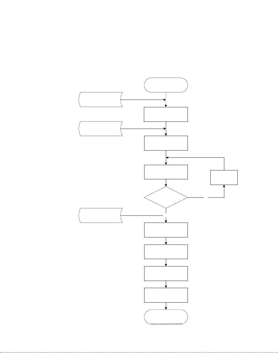
Recovery Procedure
The purpose of the W indows CE recovery process is to
update the boot.rom of the u nit’s flash memory and
restore NK.bin and CE.ini onto the unit’s CF. The
following flowchart will describe the comple te
recovery process:
Start
Genesis Card
Put BIOS intoflash
memory
Boot Card
Boot the unitwith new
BIOS and MS-DOS
6.22
Transfer MS-DOS
system files ontoCF
FormatCF
Is
COMMAND.COM
on the CF ?
ATA Card (Optional)
Boot unitwithWindows
PTC-2124 Windows CE Software Guide 37
Yes
Transfer NK.BINand
CE.INIonto CF
TFLASH BOOT.ROM
form ATA/SRAM into
flash memory
CleanupMS-DOS
files, utilities, and tools
from CF
CE OS
Finished
No
Page 50

Chapter 3 Configuring TN-3270/5250
Three (3) Card Process
The procedure for recovering the Windows CE unit by
using the three (3) card process is as follows:
1. Insert the 1 MB SRAM genesis card into slot 0 of
2. Perform the genesis boot sequence as described in
3. Recovering unit sho uld boot up with BIOS and
4. Remove the genesis card from slot 0 .
5. Insert the boot card into the slot 0 of the unit.
6. Perform the reset sequence (cool boot) then the
7. Follow the on-screen directions. W hen prompted,
the unit. Refer to the unit’sUser’sGuide.
the section titled “Genesis Utility” on page 24
Then the unit should alarm during the genesis
process (about 18 beeps).
hang after the genesis processis finished.
machine will boot into MS-DOS mode.
remove the boot card from slot 0 and insert ATA
card with Windows CE OS, Windows CE boot
loader, and MS-DOS tools/utilities into slot 0.
.
8. Once the files are copied and WindowsCE boot
loader (Boot.rom) is flashed into flash memory,
remove the ATA card as prompted on the screen.
9. Perform the reset sequence (cool boot) then the
recovering unit will boot with Windows CE OS
(e.g. Start the TouchPanelcalibration sequence).
38 PTC-2124 Windows CE Software Guide
Page 51

Windows CE Power Management
Power Management
This section describes Windows CE power
management as implemented on Symbol’s PTC-960M/
2124/2134 W in CE 2.12 (Microsoft version images)
based product line.
For information on user configuration of Power
Management features, see the section of this guide
titled “Power Applet” on page 103
Windows CE Power Management
The Windows CE kernel recognizes three different
power management states. These are summarized in
the fo llowing table:
.
PM State Comments
On Threads are actively executing in
the system. Since interrupt
handlers are implemented as
threads of execution in the
Device.exe process, the On state
includes interrupt handlers.
Idle No threads ar e scheduled for
execution. Generally, this means
that there are no interrupts
pending and no I/O is in progress.
Suspend The unit is turned off and must be
“resumed” before application s or
device drivers can execute.
PTC-2124 Windows CE Software Guide 39
Page 52

Chapter 3 Configuring TN-3270/5250
These three kernel states comprise a very high-level
and generic power management system. While in the
Windows CE On state, Symbol’s SC400-based units
implement a multi-tiered s ystem of power
management states t hat optimize power consumption.
AMD Elan SC400 Power Management
The SC400 Power Manage ment Unit (PMU) supports
7 distinct power management states. These states are
summarized below:
PM State Clock Speed Comments
Hyper-speed 66 or 99
MHz
High-speed 8, 16, or 33
MHz
Low-speed 1,2,4,or8
MHz
Standby N/A When the CPU is awakened from Standby
Temporary
Low-speed
Same as
Low-speed
The CPU clock of 33 MHz is multiplied by 2 or
3 in this mode, to produce an effective clock
speed of 66 or 99 MH z. This mode is relatively
power intensive, not only because of the high
clock speed but also because a special
Phase-Locked-Loop (PLL) must be running to
supply the mu ltiplied clock signal to the
SC400’sCPUcore.
This mode conserves power at the expense of
CPU performance. Note that the ISA bus runs
at 8 MHz. Setting Low-speed mode below 8
MHz may impact performance of some devices.
The CPU clock is stopped. The CPU can
re-awaken to service “activities” (see below).
mode as a result of a secondary activity (see
below), it goes into Temporary Low-speed mode.
When the activity se rvice is complete, the CPU
will go back into S tandby m ode.
The CPU clock is stopped and various SC400
peripherals are powered down. The CPU will
re-awakenwhenoneormore“wake sources” is
asserted (see below).
40 PTC-2124 Windows CE Software Guide
Page 53

AMD Elan SC400 Power Management
PM State Clock Speed Comments
Suspend N/A The CPU enters this mode when it determines
that the battery power level has fallen below an
acceptable threshold. This mode is similar to
Suspend mode, but the CPU will not resume
unless adequate power is available.
Critical
Suspend
N/A This mode conserves power atthe expense of
CPU performance. Note that the ISA bus runs
at 8 MHz. Setting Low-speed mode below 8
MHz may impact performance of some devices.
For more information on SC400 PMU states consult
the SC400 documentation set, available from AMD.
The SC400 PMU supports the concept of “activities” to
keep the processor running at high speed and to
awaken it from standby mo de. Primary activities
cause the processor to jump directly to High-speed or
Hyper-speed (if enabled) mode. Secondary activities
cause the processor to leave Standby mode by g oing
into Temporary Low-speed mode. T h e activity handler
can allow the processor to return to Standby mode or
force it to a higher activity level.
Note: Symbol’s Windows CE kernel does
not use Standby mode or activities.
The SC400 PMU also supports w ake sources to bring
the processor out of the Suspend state. The major
wake sources enabled in the PMU are battery failure
and the suspend/resume button. Other wake sources,
such as Ring Indicate, are handled outsidethe SC400
PMU.
PTC-2124 Windows CE Software Guide 41
Page 54

Chapter 3 Configuring TN-3270/5250
APM And Windows CE
It is commonly thought that Windows CE supports
Advanced Power Management (APM). However, this
is not the case. APM and its successor, Advanced
Configuration and Power Interface (ACPI), are
specific to PCs running desktop Windows.
Symbol Windows CE Power Management
Symbol’s implementation of Windows CE uses many
of the SC400 PMU modes to modulate power
consumption while the system is in the various kernel
modes. The following table summarizes t he pow er
management modes in Symbol units:
Unit
Kernel
PMU
Comments
Mode
Sprint On Hyper Clock speed is doubled or tripled (66 MHz
Run On High Clock speed is set according to High-speed
Walk On Low Clock speed is set according to Low-speed
Inactive On Low Clock speed is set according to Low-speed
Suspend Suspend Suspend Unit is powered off. When awakened, it will
Mode
Mode
or 99 Mhz). This m ode can be disabled to
conserve power.
mode co nfiguration. This mode cannot be
disabled, but its duration can be made very
brief.
mode. This mode cannot be disabled.
mode. The clock speed in Inactive mode
doesnothavetobeidenticaltotheWalk
mode s peed. In this mode, the display is put
into a low-power mode (“turned off”)and
the backlight is powered down.
continue execution from where it entered
Suspend mode.
42 PTC-2124 Windows CE Software Guide
Page 55

Symbol WindowsCE Power Management
Unit
Mode
*See
note
Kernel
Mode
Idle *See
PMU
Mode
note
To avoid confusion between unit mode t ypes and
APM, unit mode names have been chosen to avoid
overlapping.
Comments
*The kernel Idle mode can be e ntered from
any of the PMU or unit modes other than
Suspend. Idle mode means that n o threads
are scheduled for execution. In idle mode,
the CPU is halted using the HLT
instruction to c onserve power. It resumes
operation w hen an interrupt occurs or a
new thread is ready to execute.
Note: Unless otherwise noted, references to
power management modes refer to
“unit modes” as opposed to “kernel
modes” or “PMU modes”.Also,
“activities” generally refers to
device/thread activities (described
below), as opposed to SC400 PMU
“activities”.
Each mode has a time-out associated with it. The
time-out value controls how long the unit will remain
in that mode before dropping to the next slower mode.
If a device or thread activity occurs, the unit will jump
to the highest enabled mode; this will be either Sprint
or Run mode. These time-outs can be controlledvia a
control panel applet or directly, using the S ymbol
Power Management SDK. Both of these mechanisms
are described in subsequent sections. Modes can be
entered directly using SDK calls as well as via
time-outs or device/thre ad activities.
PTC-2124 Windows CE Software Guide 43
Page 56

Chapter 3 Configuring TN-3270/5250
The power management system is implemented
cooperatively between the W indows CE OEM
Adaptation Layer (OAL), a specialized power
management driver, and power management aware
device drivers. These software components are
accessibleviathePowerManagementSDK.
For more information on SDK calls, refer to the
SC400 Windows CE SDK Programming Guide.
Online And Offline Configuration
The power management system on Symbol’sSC400
product line supports differentiation between online
power and offline power. Online power is available
when the unit is c onnected to an A/C power source,
such as a charger or a cradle. Offline power is
supplied by batteries.
Thefollowingtablesummarizesthedefault
configurations.
Mode Name Online/Offline Settings
Sprint Disabled
Run 33 MHz / 4 seconds
Walk 8 MHz / 32 seconds
Inactive 8 MHz / 3 2 seconds
44 PTC-2124 Windows CE Software Guide
Page 57

Symbol WindowsCE Power Management
Drivers And Thread Activities
Transitionsbetween unit modes are controlled
primarily by a specialized power management driver
which monitors driver/thread activities. When such an
activity occurs, the unit jumps to the highest enabled
mode (Sprint or Run mode) and reloads the associated
transition timer. If the unit is already in that mode,
the timer is reset.
The following system events cause an activity
notification:
• Ring Indicate on a PCMCIA modem.
• Ring Indicate on a system serial port (including
the currently selected cradle connector, if enabled)
• Good-link on the Ethernet in terface (i.e., “the light
is on in the hub”). Good-link will keep the system
in the highest enabled mode as long as it is active
and the unit is docked in a cradle. This doesn’t
cause battery drain, since the cradle docking
status requires AC power.
• Keyboard/Keypad k ey presses.
• Stylus taps on the touch screen.
• ATA disk interrupts, including Compact Flash
cards and the unit’s internal boot drive.
• Received data on any serial port.
• Real-time clock interrupts (IRQ 8).
If necessary, a pplications can simulate activity using
the P owNotifyActivity() SDK call. See the SC400
Windows CE SDK Programming Guide for more
information on this API routine.
PTC-2124 Windows CE Software Guide 45
Page 58

Chapter 3 Configuring TN-3270/5250
Received serial port data is only treated as an activity
if the SC400 PMU is in Low-speed or Temporary
Low-speed mode. This avoids significant internal
overhead in communication between the serial driver
and POWMAN because activities wi ll only be
generated when the unit times out into Walk or
Inactive mode. This optimization is important because
of the time-sensitive nature of RS-232
communications. While the PMU is in High-speed
mode, no activity notifications will be generated.
Power Management Initialization
Power management initialization culm inates in
setting the SC400 PM U to the highest enabled unit
mode and startin g the assoc iated mode timer. To get
to this point, the unit passes through three distinct
phases following a reboot:
1. The bootl oader initializes the SC400 P M U.
Currently, it sets the PMU to High-speed mode at
33 MH z with no timeout. It loads the Windows
CE image from the internal ATA card
(\HardDisk) and transfers control to it.
2. TheWindowsCEHALinitializestheSC400PMU.
Currently it sets the PMU to H igh-speed mode at
33 MH z with no timeout. Windo ws CE dev ice
drivers an d the windows subsystem are initialized
at the same speed.
46 PTC-2124 Windows CE Software Guide
Page 59

Symbol WindowsCE Power Management
3. ThePOWMANdevicedriverisloadedduring
device driver initialization. It is responsible for
initializing the PMU with its Sprint, Run, Walk,
and Inactive settings, transitioning to the highest
enabled mode, and starting the associated mode
timer. However, it defers this processing until it
determines that the windowing subsystem and
the shell have bee n initialized. (Inte rnally, it uses
the IsAPIReady() system call for this purpose.)
Once the windows subsystem and the shell are up
and running,it transitions to Sprintor Run mode
(as enable d) and starts the associated timeout.
Once step 3 is complete,the unit w ill be running
normally. P OWMAN defers starting the first mode
time-out until device drivers and windows are
initialized to avoid having the time-out occur while
Windows CE is still initializing.
Note: If an application is launched before
the shell completes initialization,
power management SDK calls will
have unpredictable behavior.
Applicationsthat are launched
automatically should use
IsAPIReady(SH_SHELL) before
calling power SDK functions.
PTC-2124 Windows CE Software Guide 47
Page 60

Chapter 3 Configuring TN-3270/5250
Magic Packet Mode
Another feature of the PT C-2124’s power
management is the ability to enable the Magic Packet
Wake Up mode (Magic Packet is an E-Wake utility
developed by AMD) when the unit is docked in a
cradle and in the Suspend state. Magic Packet mod e
provides the ability to remotely wake up t he u nit by
using the Ethernet connection established through
the cradle. This allows the unit to be remotely
accessed and managed even if the Suspend state has
been entered.
When the unit is manually put into the Suspend state
(while docked in a cradle), the Ethernet controller will
automatically enable Magic Packet mode. While in
Magic Packet mode, the unit will monitor all incoming
frames to determine if any of them is a Magic Packet
frame. A Magic Packet frame is a unit of data that is
sent by a network manager, via Ethernet connection,
from a remote site with the intent to wake up the
unit. When a Magic Packet frame is received and
detected, the Ethernet controller will wake up the
unit and disable Magic Packet mode. The unit then
regains full functionality, including network
accessibility.
48 PTC-2124 Windows CE Software Guide
Page 61

SC 400 Power Control
S
SC 400 Power Control
100or66MHz
(Hyperspeed) or
33 MHz (Highspeed-
Default)
Processor Step
down will be
transparent to the
user
Control Panel: SetSpeed Utility, save reg.
SDK:
Set Speed
High Speed timeout + Low
Speed timeout
Standby timeout
Suspend timeout
High Speed timeout + Low
Speed timeout = 4 seconds
8Mhz
(LowSpeed)
Standbytimeout = 32 seconds
Standby
8MHz
uspend timeout = 32 seconds
Suspend
PTC-2124 Windows CE Software Guide 49
Page 62

Chapter 3 Configuring TN-3270/5250
Cradle Overview
The Symbol PTC-1124 De sktop/Vehicle Cradle is a
specialized docking station that is used for the
PTC-2124. The cradle provides the following services:
• External Serial Port Connection,
• Battery Recharging Connection,
• External Ethernet Connection,
• External Keyboard Connection.
The SC-1124 is designed for use on a flat horizontal
surface, such as a table or de sk. The VC-1124 sec urely
mounts inside a vehicle’s c ab (using a vehicle m ount).
Cradle Information
Each cradle holds one PTC and o ne spare battery
pack at a time and works with the PTC in two ways:
1. It acts as a communication link. Through the
cradle, the PTC can se nd data to and receive data
from a host computer or other serial devices.
2. The cradle provides power for rapidly recharging
the PTC’s lithium-ion battery pack and a spare
battery pack when the PTC and spare pack are
installed in the cradle.
Thecradlecanbeconnectedviacabletoanetwork
throughits Ethernetport or to externalserial devices
via its three 9-pin RS-232 serial ports. In addition, a
keyboard can be connected to the cradle for use with
the installed PTC.
50 PTC-2124 Windows CE Software Guide
Page 63

PTC-2124 Cradle Interaction
PTC-2124 Cradle Interaction
The PTC-2124 only has one COM port available for
use by peripherals. Th e PTC-2124 uses an electrically
controlled serial switch-box wit h a 9-wire interface to
provide additional s erial ports for this single CO M
port.
The PTC-2124 provides IrDA on COM1 and wired
serial on COM2. An infrared sensor on the PTC-2124
provides the IrDA outlet. A Connector Pod on the
PTC-2124 pr ovides the serialoutlet.
The following table summarizes the possibilities for a
PTC-2124. When out of the cradle, C OM1 is availabl e
as IrDA and COM2 is available through an attached
Connector P o d. When docke d, COM1 is available as
IrDA and COM2 is re-routed to one of the DB-9 serial
connectors.
Cradle COM1 Outlet COM2 Outlet
Undocked
Docked
IrDA on
PTC-2124
IrDA on
PTC-2124
Connector Pod on
PTC-2124
DB-9
on cradle
PTC-2124 Plugged Into A Cradle
IrDA
Power
Connector
1124 Crad le
RS232 DB-9
Transceivers
13-Pin
RS232
Transceivers
RS232
Transceivers
(Port 1)
DB-9
(Port 2)
DB-9
(Port 3)
PTC-2124
Conn Pod
(COM 2)
(COM 1)
PTC-2124 Windows CE Software Guide 51
Page 64

Chapter 3 Configuring TN-3270/5250
Cradle Serial Interface
Thecradleserialinterfaceisimplementedusinga
communication chip and cradle electronics to create
four multiplexed RS232 serial ports, one internal port
and two external ports. Since the serial ports are
multiplexed , only one port can be active at a time.
Serial Port 1 DB9 Connector (Male Pins)
Serial Port 2 DB9 Connector (Male Pins)
Serial Port 3 DB9 Connector (Male Pins)
Control Port No Connector, Internal to unit
The Vehicle/Desktop-1124 Cradle supports the
communication chip inter face to the PTC-2124 unit
via the Cradle Contacts. The Communication
Interface uses COM 2 (2F8 Hex) on the PTC-2124
unit. This interface is specifically designed for use
with the Symbol cradles and is provide d by the
communication chip. The Vehicle/Desktop-1124
Cradle uses a wired im plementation of the interface.
ThesameCOM2Portisusedforboththe
Vehicle/Desktop-1124 Cradle’s Serial Connectors and
the serial port in the PTC-2124 u nit’s Connector Pod.
Hence, only one COM interface can be used . When the
PTC-2124 is placed in a cradle, the cradle’sserial
ports can be used if the un it’s application program
uses the cradle serial routines from the PTC-2124
SDK. (Refer to the PTC-2124 SDK for softw are
details)
Note: When the connector Pod is connected,
the Serialconnection is a 4-wire
implementationonly. When attached
to a cradle, the active port is a full
9-wire serial port implementation.
52 PTC-2124 Windows CE Software Guide
Page 65

PTC-2124 Cradle Interaction
The Optical Serial Signals use the cradle contacts on
the PTC-2124 unit as shown below:
Pin Signals Description
1 OTXD Optical Transmit Data
2 ORXD Optical Receive Data
3 OTXS# Optical Transmit Status
4 ORXS# Optical Receive Status
In the Optical Serial Interface, two lines are used for
Receive and Transmit data and two lines are used for
status lines. The two status line s (OTXS#, ORXS#)
provide communication status information via
Time-Division-Multiplexing. In this technique, the
status information is embedded in the status dat a of
each line.
The Status Word, like a normal Data Word, begins
with a Start Bit and ends with a Stop b it. H owever,
the Status Word uses three Stop bits to provide an
easy identification of the end of the word.
The Status Lines operate at a 38.4 KBPS data rate,
where as the Data Lines operate at the rate
programmed for the internal communication chip
UART controllingthe Serial Port. The Serial
communication chip UART can be programmed to
support the following standard communications
functions:
• Data Rate 75 to
115.2 Kbps.
• Parity Even, Odd,
None.
PTC-2124 Windows CE Software Guide 53
• DataWidth5,6,7,or8
bits.
• Stop Bits 1 o r 2.
Page 66

Chapter 3 Configuring TN-3270/5250
DTR and RTS Latching
The Vehicle/Desktop-1124 Cradle provides DTR an d
RTS latching on inactive Serial Port 3 to prevent the
connected device from dropping the communication
link with the PTC-2124. Prior to switching to another
Serial Port, the cradle will latch the DTR and RTS
lines at their cur rent levels. For example, if the signal
is currently high, the line will be latched high, or if
the signal is currently low, the line will be latched
low. This feature is particularly useful when
connecting to devices such as WAN radios.
Ring Indicator
In order to allow the Ring Indicator (RI) signal to
reach the PTC-2124 unit from any serial port (ac tive
or not), the RI sig nals from all Serial Ports are
logically Ored together. The RI signal can be used to
wake the PTC-2124 unit from Standby or Suspend
Modes.
54 PTC-2124 Windows CE Software Guide
Page 67

PTC-2124 Cradle Interaction
DB-9 Serial Connector Pinout
Thepin-outoftheRS232portDB-9(malepins)
connectors are as shown in the tables below:
Pin Signal Pin Signal
1CD 6DSR
2RXD 7RTS
3TXD 8CTS
4DTR 9RI
5GND
Ethernet Port
The 10 Mbps Ethernet Port is available via an RJ-45
connector. The Ethernet Port is located on t he r ight
side of the cradle and interfaces to the Cradle
Contacts. Th e cradle RJ-45 port will be wired as DCE
accepting a standard male LAN cable. The Ethernet
RJ-45 connector pin-out is as follows:
PIN SIGNAL PIN SIGNAL
1TXD+ 5 NC
2TXD- 6 RXD3RXD+ 7 NC
4NC 8 NC
Note: The E thernet Port is located on both
the Desktop and Vehicle
configurations, however, the port will
typicallybeusedonlyinaDesktop
configuration.
PTC-2124 Windows CE Software Guide 55
Page 68

Chapter 3 Configuring TN-3270/5250
Keyboard Port
The Vehicle/Desktop-1124 Cradle supports an
external PS/2 Keyboard Port which is located on the
right side of th e unit. The PS/2 Keyboard Port
supports the following connector pinout:
Pin SIGNAL DESCRIPTION
1 KB_DATA Keyboard Data
2 N/C Not Connected
3GND Ground
4 5VSW Keyboard Power (+ 5 VDC)
5 KB_CLOCK Keyboard Clock
6 N/C Not Connected
Note: Permanent Keyboard damage may
occur if the user connects or
disconnects the k eyboard from the
cradle'skeyboardconnector while the
unit is docked, unless the unit is
suspended first.
56 PTC-2124 Windows CE Software Guide
Page 69

CRADMON.EXE
CRADMON.EXE
Cradmon is an executable file that sends cradle status
change notifications to applications and adds the
Cradmon icon to the taskbar.
To run Cradmon.ex e and add the Cradmon icon to
the task bar, follow these steps:
1. Tap on the Start menu button.
2. Select Run,thenBrowse.
3. Double-tap on the Windows folder.
4. Select Cradmon.exe.
5. Tap on OK,thenOK again.
The Cradmon popup menu items are briefly described
below:
• Tapping on Properties… launches the Cradmon
main c onfiguration dialog box.
• Tapping on About... dis plays Cradle Monitor
version information.
• Tapping on Cancel closes the Cradmon popup
menu.
• Tapping on Exit causes Cradmon to terminate
and removes the Cradmon icon from the taskbar.
PTC-2124 Windows CE Software Guide 57
Page 70

Chapter 3 Configuring TN-3270/5250
The Cradmon Dialog Box
The Cradmon dialo g box is the main configuration
interface for Cradmon and can be accessed through
the Properties... menu item on the Cradmon icon
popup menu. It contains two tabs, the Status tab and
the Prop erties tab. Tapping on a tab heading will
select that tab page.
The Status Page
The Status tab page displays different types of
cradle-related status information. It is for monitoring
only and offers no user action. The Status page
displays information regarding the following:
• Whether the unit is docked or u ndocked,
• Driver version,
• List of ports that are automapped,
• Polling Interval.
58 PTC-2124 Windows CE Software Guide
Page 71

CRADMON.EXE
The Docking Page
The Docking tab page allows the user to select sound
options for Docking Notification. The user can
choose either Do Nothing (no sound) or Beep.
The Undocking Page
The Undocking tab page allows the user to select
sound options for Undocking Notification. The user
can choose either Do Nothing (no sound) or Beep.
PTC-2124 Windows CE Software Guide 59
Page 72

Chapter 3 Configuring TN-3270/5250
The Config Page
The Config tab page displays the Configure Cradle...
button.
When tapped, the Configure Cradle... button brings
uptheCradlesetupdialogbox.Thisisthesamedialog
box that is displayed when the Cradle Configuration
Control Panel Applet is initiated.
For more information on this, refer to the s ection titled
“Cradle Configuration Applet” on page 102
of this
guide.
60 PTC-2124 Windows CE Software Guide
Page 73

The PCMCIA Card
PCMCIA
The PCMCIA Card
A PCMCIA Card is a small form factor device about
the size of a credit card. The card provides superior
expansion capability to portable and notebook
computers.
The PTC-2124 uses an Intel PCMCIA controller to
access the two PCMCIA slots (slot 0 and slot 1) which
are accessible through the access door on the top of
the unit. Slot 0 is closest t o the display and slot 1 is
farthest from the display.
The PCMCIA slots in the PTC-2124 will support a
variety of cards. This includes spinning drives,
memory,modem,radio,andnetworkcards.
PTC-2124 Windows CE Software Guide 61
Page 74

Chapter 3 Configuring TN-3270/5250
PC cards can be one of the following types:
Ty p e Description
Type I 3.3 millimeters thick
Type II 5 millimeters thick
Type III 10.5 millimeters thick
Type I Extended 3.3 millimeters thick, with 40 millimeters
Type II Extended 5 millimeters thick, with 40 millimete rs
Location of External PCMCIA Slots:
extended length
extended length
Slot 0
Slot 1
62 PTC-2124 Windows CE Software Guide
Page 75

Formatting an SRAM or ATA Card
With the architecture provided by the PCMCIA
standard, several types of PC cards are available.
Some examples are listed below:
• Data Storage cards,
• Serial interface cards.
Formatting an SRAM or ATA Card
Data storage card can be of solid state or rotating
media type. PTC-2124 PCMCIA d ri ves accept m emor y
cards ranging from 1 MB to 4 MB i n size. If using a
new memory card, it mu st be formatted prior to
writing data to it.
When an unformatted or unrecognized card is
inserted into the PTC-2124, Windows CE will display
a mes sage asking if the user wants the system to
format the ca rd.
If the user selects Yes, the storage card will be
automatica lly formatted.
Note: If Yes is selected, any files on the storage
card will be erased.
PTC-2124 Windows CE Software Guide 63
Page 76

Chapter 3 Configuring TN-3270/5250
This section d escribes how to configure and use
DCDWEDGE for Windows CE. The DCDWEDGE
application accepts da ta from device drivers written
according to Symbol’s Data Co llection D evice (DCD)
specification and converts it into keyboard events.
This is often referred to as “wedging” the data into the
keyboard queue. The “wedging” mechanism allows
applications to receive data notifications from DCD
devices in the form of keyboard input.
System Requirements
In order to use DCDWEDGE, the following minimum
system r equirements must be met:
• Windows C E 1.20 or later.
• Quarter-VGA display or larger (for example,
• DCDAPI32.dll must be installed.
• At leas t one DCD-compliant device d river must be
DCDWedge
PTC-960M, PTC -2124, PTC-2134).
properly installed. This driver may impose
additional system requirements.
Data being “wedged” into the keyboard queue must be
numeric d ata or string data. That is, not all possible
DCD data types are supported by DCDWEDGE .
64 PTC-2124 Windows CE Software Guide
Page 77

DCDWEDGE Operation
DCDWEDGE Operation
Overview of DCD
A complete discussion of the Data Collection D evice
(DCD) programming model is beyond the scope of this
document. H owever, a basic understanding of DC D i s
important in order to understand how DCDWEDGE
works.
The DCD application pro gramming interface does not
deal with data from devices in t erms of hard-coded
data types. DCD devices supply a stream of “data
events”, each of which consist of data name/value
pairs. The data name is a human-readable name that
generally provides some indication of what the data
represents. For exam ple, a given device might have
two data fields: “te xt data” and “numeric data.”
The DCD programming model supports many types of
data; however, DCDWEDGE only s upports text and
numeric data. In the example data event above, the
“text data” field would have t he “text” data type and
the “numeric data” field would have a “numeric” data
type.
Example data inputs using the format described
above might be:
• First data event
“text data” equals “foo”
“numeric data” equals 100
• Second data event
“text data” equals “bar”
“numeric data” equals 3
PTC-2124 Windows CE Software Guide 65
Page 78

Chapter 3 Configuring TN-3270/5250
• Third data event
Note that the third data event contains an extra data
field. It is acceptable for D CD devices to use a
different format for each data event (although in
general most do not). DCDWEDGE will ignore data
events that do not contain all of the named fields that
it is configured to expect.
The advantage of having named data fields is that it
allows app lications such as DCDWEDGE to process
them without any special knowledge of what they
mean. T he DCDWEDGE user can simply “browse” the
data fields he or she is in terested in, set up the
appropriate wedge formatting, and DCDWEDGEwill
do the rest.
For more information about DCD API, refer to the
SC400 Windows CE SDK Programming Guide.
“text data” equals “baz”
“numeric data” equals 405
“event time” equals 655301
Data Formatting
DCDWEDGE is capable of convertingcharacterstring
or numeric data into keyboard even ts. It is also
capable of formatting the data using a combination of
standard text or special keys (such as Alt, Return,
Escape, and function keys).
For example, assume that the value of the “Text Data”
field for a given D CD data event is “demo dat a”.In
this case, DCDWEDGE will generate keyboard even ts
that spell out:
wedge: demo data[RETURN]
Here, [RETURN] indicates a carriage return, not the
text “[RETURN]”. Whichever application currently
has the keyboardinput focus will receive this data,
exactly as if it had b een typed in at the keyboard.
66 PTC-2124 Windows CE Software Guide
Page 79

DCDWEDGE Operation
User Interface
The primary user interfaceto DCDWEDGE is via its
icon on the taskbar. To place this icon on the taskbar,
follow these steps:
1. Tap on the Start menu button.
2. Select Run,thenBrowse.
3. Double-tap on the Windows folder.
4. Select DCDWedge.exe.
5. Tap on OK.
Tapping this icon brings up the DCDWEDGE popup
menu.The DCDWEDGE popup menu items are
briefly described below:
• Tapping on Exit causes DCDWEDGE to
terminate and removes the DCDWEDGE icon
from the taskbar.
• Tapping on Properties… launches the
DCDWEDGE main c onfiguration dialog bo x.
• Tapping on Config… launches a dialog box that
allows the user to savethe current c onfiguration
or load a stored configuration.
• Tapping on About… launches a dialog box that
displays version information about DCDWED GE,
the DCDAPI32 DLL, and the currently selected
driver.
• The last menu item, labeled Enable or Disable,
enables or disablesthe selected device. This menu
item is grayed out if n o device is s elected or if the
selected device is not configured.
PTC-2124 Windows CE Software Guide 67
Page 80

Chapter 3 Configuring TN-3270/5250
DCDWEDGE Configuration Options
DCDWEDGE requires configuration in the f ollowing
four major a reas:
1. Which DCD device to use.
2. Configuration information for that DCD device.
3. Formatting information indicating how to process
4. Options controlling DCDWEDGE behavior at
All of these options are described in detail in the
section titled “
However, this section provides a quick summary of
the options alluded to in (4) above.
DCDWEDGE is capable of providing audible feedback
when it enables or disables the currently selected
DCD device, or when t he device generates a data
event that DCDWEDGE can pr ocess. The audible
feedback c an consist of b eeps or no sounds at all.
Different a udible feedback c an be associ ated with
device enabling, device disabling, and data eve nts.
DCDWEDGE will not generate audible feedback if it
cannot convert a data event into keyboardevents – if
the data event does not contain all the named data
fields DCDWEDGE expects, for example.
data events from th e DCD device.
startup or when DCDWEDGE receives a data
event from the currently configured DCD device.
DCDWEDGE Dialog Box” on page 71.
DCDWEDGE can be configured to automatically
enable the selected DCD device when it is invoked. It
canalsobeconfiguredtodisablethedeviceafterit
receives a data event or after a given time has elapsed
and no data events have occurred. Depending on the
DCD device, automatic disabling can help conserve
battery power.
68 PTC-2124 Windows CE Software Guide
Page 81

Running DCDWEDGE
Some DCD device drivers supply icons that can be
displayed on the taskbar in place of DCDWEDGE’s
defaulticonattheuser’s request. In addition,
DCDWEDGE can be configured to use its most recent
configuration whenever it is restarted or to prompt
the user for a configuration each time. It can also b e
configured to not prompt the u ser if it restarted with
no configuration in place. However, DCDWEDGE will
always display a warning at start-up time indicating
that it cannot be enabled until a device is sele cted and
configured.
Running DCDWEDGE
DCDWEDGE is fairly simple to set up, and once it is
configured it is very simple to use. This section
describes how to set up and use DCDWEDGE.
Setting up DCDWEDGE
When DCDWEDGE is launched for the first time it
will automatically launch the DCDWEDGE dialog box
(described in the section titled “
Box” on page 7 1) to prompt the user for configuration
information. Typically, users plan to use DCDWEDGE
to supply keyboard d ata for a particular ap plication
and they are familiar with the f ormat of keyboard
data the application expects. They generally also
expect to use DCDWEDGE with a specific device, such
as a barcode scanner or magnetic stripe reader, for
which they have already installed the device driver.
DCDWEDGE Dialog
PTC-2124 Windows CE Software Guide 69
Page 82

Chapter 3 Configuring TN-3270/5250
Setting up DCDWEDGE consists of the following
steps (These steps are described in more detail on the
following pag es):
1. Select a DCD device using the Device page.
2. Configure the DCD device using the DCD page.
3. Define the data format rules, which D CDWEDGE
4. Optionally, set up other DCDWED GE
Once these steps are complete, the u ser can launch
their application, and enable the DCD device.
DCDWEDGE is ready to go.
Using DCDWEDGE
In normal operation, the most users w ill have to do
with DCDWEDGE is enable and disable the currently
configured DCD device.This is done using the popup
menu that is launched when the user taps on the
DCDWEDGE icon on the taskbar, and selecting the
Enable/Disable menu item.
will use to convert DCD data events into keyboard
data for the application, using the Wedge page.
configuration parameters using the remaining
pages.
For some applications, it may be convenient to
configureDCDWEDGEtodisablethedevice
automatica lly after a data event, or if a certain
amount of time elapses with no data events. This can
be set up through the Activatio n page of the
DCDWEDGE dialog box.
70 PTC-2124 Windows CE Software Guide
Page 83

DCDWEDGE Dialog Box
Some users may wish to use DCDWEDGE with
different devices at different times, or with multiple
configurationsfor the same device. DCDWEDGE
supports saving and loading named configurations
using the Wedge Configurations. This dialog is
launched using the Configs… menu item of the
DCDWEDGE popup menu. To cause DCDWEDGE to
always prompt the user for which configuration to
use, clear the Use last configuration check box and
check the Prompt user if no config check box in the
Miscellaneous page of the DCDWEDGE dialog box.
DCDWEDGE Dialog Box
The DCDWEDGE dialog box is the primary
mechanism for configuring DCDWEDGE. It is
accessed by tapping on the Properties... menu item
on the icon popup menu. If the DCDWEDGE dialog
box is closed without a DCD device selected and
configured, or without the wedge formatting rules
being specified, DCDWEDGE will generate a warning
message.
This section des cribes ea ch of the tabs in the
DCDWEDGE dialog box. Tapping on a t ab heading
will select that tab page. Once the first three pages
(Device, DCD, and Wedge) are filled in, the device is
ready to enable. The other pages control other aspects
of DCDWEDGE behavior, such as automatic device
activation and deactivation, audible feedback, and so
forth.
Note: When the user launches the DCDWEDGE
dialog box, DCDWEDGE will automatically
disable the selected DCD device if it is
enabled. When the dialog box is closed, the
user must manually r e-enable the device
using the DCDWEDGE popup menu’s
Enable menu item.
PTC-2124 Windows CE Software Guide 71
Page 84

Chapter 3 Configuring TN-3270/5250
Device Page
The Device page allows users to select one of the DCD
devices installed on their system. This is done simply
by double-tapping one of the entries in the device list.
When the device is selected, its name will appear at
the top of the page, in the edit box labeled “Device.”
Note: Changing the device will invalidate the
device’s configuration and the wedge format
configuration. In other words, the first three
tab pages of the DCDWEDGE dialog box
will need to be filled in just as if
DCDWEDGE were being started for the
first time. Because of this, if the user
attemptsto change the device, DCDWEDGE
will prompt them for confirmation.
72 PTC-2124 Windows CE Software Guide
Page 85

DCDWEDGE Dialog Box
DCD Page
The DCD page allows users to review the
configuration of the selected DC D device and upd ate it
if desired.
The Data… and Hardware… buttons allow the user
to launch the DCD device’s data and hardware
configuration dialog boxes, respectively.
Accordingto the DCD programming model,“hardware
configuration” affects the device driver’sbasic
interaction with the device’s physical hardware. This
kind of configuration is usually done once for a
particular handheld device, if at all, and should
generally be carried out with some caution. The
device’s default hardware co nfiguration is usually
acceptable.
On the other hand, “data configuration” allows the
user to control the format, type, or amount of data the
device will generate. For e xample, a barcode scanner’s
data configuration might allow the user to select
which types of labels should be decoded. As another
example, the data configuration might specify which
tracks a magnetic stripe reader might read from
credit cards. Data configuration generally needs to be
carried out more frequently than hardware
configuration, although once it’sdoneforaparticular
customer application it doesn’tneed to be changed.
PTC-2124 Windows CE Software Guide 73
Page 86

Chapter 3 Configuring TN-3270/5250
The DCD device driver provides DCDWEDGE w ith a
human readable “summary” of its configuration,
which DCDWEDG E displays in the “Current
Settings” window of the D CD page.
Note: It is possible that some DCD devices will not
export their configuration in a format that
allows it to be displayed in the “Current
Settings” window. In this case, users will
have to launch the device’s hardware and
data configuration dialogs if they wish to
review the device’ssettings.
Wedge Page
The Wedge page allows users to set up DCDWEDGE’s
data formatting rules. DCDWEDGE is capable of
sophisticated formatting of keyboard d ata based on
DCD data events. An example o f the Wedge page is
shown below:
74 PTC-2124 Windows CE Software Guide
Page 87

DCDWEDGE Dialog Box
DCDWEDGE can generate keyboard data based on
fields i n the DCD data event, on static text configured
by the user, and on “special keys” such as f unction
keys and shift-key modifiers such as the Alt key. A
simple example of DCDWEDGE’s formatting
capabilities is described in the section titled “Data
Formatting”.
As a more interesting example of D CDWEDGE data
formatting, imagine that the user’s application
contains a dialog that has two input fields, one of
which accepts a text string and one a number. To
enter data into this hypothetical dialog manually, the
user would have to type Alt-M (for M
enu) to access a
menu in the title bar of their application, then type D
(for D
ialog) to launch the dialog. They would the n
enter the text string,type the Tab keytojumptothe
next input field, type the number, and type the
Return key to close the dialog.
Static te xt is enclosed in single quotes (‘), DCD field
names are enclosed in angle brackets (<>) and special
keys are enclosed in square brackets ([]).
The four buttons at the bottom of the Wedge page
allow the user to add, edit, or delete selected data
format rules. T he Insert… and Append… buttons
bring up the Create Field dialog box, shown below:.
PTC-2124 Windows CE Software Guide 75
Page 88

Chapter 3 Configuring TN-3270/5250
This dialog allows the user to specify what kind of
data formatting rule they would like to create. These
rules are described in more detail in the following
sections. The Insert… button causes the newly
created formatting rule to be inserted ahead of the
currently s elected rule. It can also be used to create
the first Wedge formatting rule.
The Delete button deletes the c urrently selected
formatting rule. The Edit… button allows the user to
modify the contents of an existing format rule. It does
this by launching the same editing dialog boxes as the
Create Field dialog box, so it is not possible to change
the formatting r ule type.To replace one kind of field
configuration with another, delete the field
configurationand insert a new one of the proper type.
Double-tapping a formatting rule has the same effect
as tapping the Edit… button.
DCD Field Data Formatting Rules
The Wedge DCD Field dialog allows the user to choose
a DCD data field, which might be generated by the
selected DCD device during a data even t. Properly
implementedDCD drivers willinform DCDWEDGE of
all possible data fields so that they can be included in
this list. Some DCD drivers will not include all of the
possible data fields in every DCD event.
Forexample,magneticstripereaderdriversneedto
be able to read all four tracks of data from a credit
card. However, not all credit cards actually have data
on all four tracks. In this case, the driver would
simply not populate the missing tracks in i ts data
events. If DCDWEDGE receives a data event that
does not contain all of the data fields it h as been
configured to expect, i t will ignorethe data event.
76 PTC-2124 Windows CE Software Guide
Page 89

DCDWEDGE Dialog Box
A sample Wedge DCD Field dialog i s shown b elow:
The Type and Description fields on the dialogprovide
additional information about the selected DCD data
field.
Note that DCDWEDGE processes all numeric (“word”,
“dword”,and“byte”) data fields in base 10. The DCD
driver informs DC D WEDGE whether the data should
be treated as signed or unsigned. For example, a
“byte” value can range from –127 to 127 if it is sig ned,
or from 0 to 255 if it is unsigned. DCDWEDGE will
generate a keyboardevent for the minus sign if the
numeric value is both signed and negative. Consult
the SC400 Windows CE S DK Programming Guide for
more information about DCD data types.
PTC-2124 Windows CE Software Guide 77
Page 90

Chapter 3 Configuring TN-3270/5250
Text Data Formatting Rules
The Wedge Text Field dialog allows users to create
and/or edit static text to be inserted into the keyboard
queue during data events. A sa mple Wedge TextField
dialog is shown below:.
Any text that can be ente red into a “normal” Windows
edit control can be entered into the Wedge Text Field
dialog.
Special Key Data Formatting Rules
DCDWEDGE supports the use of “special keys” in its
data formatting rules. These are key sequences which
cannot be entered into a Win dows edit control and
therefore cannot be specified using the Wedge Text
Field dialog described in the section titled “Text Data
Formatting Rules”. The Special Keys dialo g allows
users to specify these characters.
78 PTC-2124 Windows CE Software Guide
Page 91

DCDWEDGE Dialog Box
Special keys fall into three major categories:
1. Shift modifiers, such as the Control, Alt,and
Shift keys.
2. Special characters, such as Return, Esc,
Backspace,andTab.
3. Function keys (F1, F2,etc).
The Special Keys dialog allows users to select keys
from each of these categories using combo box
controls. An example Special Keys dialog is shown
below:.
Many applications use Alt key c ombinations to bring
up menus and dialogs, sometimes in conjunction with
the Control key. However, capitalized letters and
certain punctuation marks that can be entered using
the Wedge Text Field dialog implicitly use the Shift
modifier key. This option is also providedin the
Special Keys dialog because some applications expect
key sequences such as Shift+F1.
Shift modifiers do not actually generate keyboard
events until DCDWEDGE generates a non-shift
keyboard event. In other words, if a shift modifier is
the last data f ormatting rule in the list, it will have no
effect on the wedged data.
PTC-2124 Windows CE Software Guide 79
Page 92

Chapter 3 Configuring TN-3270/5250
When multiple consecutive shift modifiers are present
in the list, they always generate keyboard shift key
events in the or der Alt, Control, Shift. For example,
if the formatting lists [Control], [Alt], ‘m’ and [Alt],
then [Control] and ‘m’ are functionally identical.
Both produce the following sequence of keyboard
events:
• Alt key down,
• Control key down,
•‘m’ key down,
•‘m’ key up,
• Control key up,
• Alt key up.
This behavior should not cause a problem for most
applications, since most applications do not care about
the order in which shift modifier keys are pressed.
If the same shift modifier key is repeated
consecutively in the data format list, the shift
modifier will only take effect once. F or example, the
formatting list [Shift], [Shift], ‘m’ is functionally the
same as [Shift],‘m’.
Sounds Page
The Sounds page allows users to specify what audible
feedback (if any) they choose to associate with DCD
events. A sample S ounds pag e is shown below:.
80 PTC-2124 Windows CE Software Guide
Page 93

DCDWEDGE Dialog Box
Three types of DCD events can be associated with
audiblefeedback:
• Device activation,
• Device deactivation,
• Device data events.
Changing these three setting can be accomplished by
tapping on the Activation..., Deactivation...,and
Data... buttons.Bydefault,DCDWEDGEplaysa
beep for each of these events. However, users can
choose have no audible feedba ck at all associated with
the data event.
Activation Page
The Activation p age allows users to define certain
rules governing how and when DCDWEDGE will
activate and deactivate the selected DCD device. The
Activation page is shown below:.
If Activate on start-up ischecked, DCDWEDGEwill
configure and enable the selected DCD device when it
is launched. Of course, if no device is selected, no
device will be configured.
PTC-2124 Windows CE Software Guide 81
Page 94

Chapter 3 Configuring TN-3270/5250
If Deactivate on data input is checked,
DCDWEDGE will disable the selected DCD device
after it generates a data event. This is sometimes
useful in keeping the device from “getting ahead” of
the application to which it is providing data.
If Deactivate after time-out is checked,
DCDWEDGE will deactivate the device if no data
event is generated within the time interval specified
by the slider. Depending on the device, this can h elp
conserve battery power for the handheld on w hich
DCDWEDGE and the user application a re running.
Miscellaneous Page
The Miscellaneous page is used to control
DCDWEDGE’s behavior at start-up and how it
displays itself on the system taskbar. An example of
the Miscellaneous page is shown below:.
If Use last configuration is checked, DCDWEDGE
will attempt to reload whatever configuration it used
during its previous invocation.
If Prompt user if no config is checked,
DCDWEDGE will prompt the user to configure it if no
previous configuration was saved or the Use last
configuration checkbox w as unchecked in the
previous configuration.
82 PTC-2124 Windows CE Software Guide
Page 95

DCDWEDGE Dialog Box
If DCDWEDGE finds thatone or more named
configurations have been saved, it will launch the
Wedge Configurations dialog (see the section titled
“
Wedge Configuration Dialog Box” on page 84 for
more inf ormation on this dialog). If no named dialogs
have bee n saved, DCDWEDGE will launch the
DCDWEDGE dialog box instead.
DCDWEDGE will always warn the user if no
configurationispresent,evenifbothofthese
checkboxes are unchecked. It will also warn the user
if the user attemp ts to close the Properties dialog
without configuring a device. A device is considered
unconfigured if (1) no deviceis selected, (2) no data
configuration has been created for the device, or (3) no
wedge data formatting rules have been defined.
The Taskbar Icon group box allows users to choose
how DCDWEDGE should display itself on the
taskbar. Most DCD devices supply a s et o f icons that
can be displayed on the taskbar;one of these icons
represents the device in its en abled s tate, and one
represents the device in its disabledstate.
DCDWEDGE will use these icons if the Current
device icon button is selected. It will use its own
(default)iconiftheDCDWEDGE default button is
selected or if the DCD device does not supply icons.
PTC-2124 Windows CE Software Guide 83
Page 96
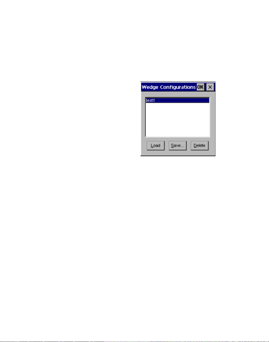
Chapter 3 Configuring TN-3270/5250
Wedge Configuration Dialog Box
DCDWEDGE allows users to store and load named
configurationsusing the Wedge Configuration Dialog
Box.This dialogis launched by tapping the Config…
menu item in the DCDWEDGE icon popup menu. An
example of the Wedge Con figuration dialog box is
shown below:.
The user can load a saved configuration either by
selecting a configuration name and tapping the Load
button or by double-tapping a configuration name.
Saved configurations can be deleted by selecting a
configurationname and tapping the Delete button.
When the user taps the Save… button, they are
prompted for the n ame of a new or ex isting
configuration.If they enter the name of an existing
configuration (or if they select a configuration prior to
taping the Save… button) that configuration will be
overwritten. If the user enters the name of a new
configuration, tha t configuration will be created.
Note: When the user launches the Wedge
Configuration dialog box, DCDWEDGE
will automatically disable the selected DCD
device if it is enabled. When the dialog is
closed, the user must manually re-enable the
device using the DCDWEDGE popup
menu’s Enable menu item.
84 PTC-2124 Windows CE Software Guide
Page 97

Other DCDWEDGE Popup Menu Items
Other DCDWEDGE Popup Menu Items
In addition to the Properties… and Config… menu
items, the DCDWEDGE icon popup menu has other
menu items that are simple enough that all of them
can be discussed in a single section.
The About… menu item displays version information
about DC DWEDGE and a copyright notice. It also
displays info rmation about DCDAPI32 (t he system
DLL that actually implements the DCD interface to
DCD devices). Also, if a DCD device is selected, the
device’s name and version information will be
displayed.
The Enable/Disable menu item allows the user to
enable or disable the DCD device. It will be grayed out
ifthedeviceisunconfigured(seethesectiontitled
“
Miscellaneous Page” on page 82 for a definition of
“unconfigured”). The text of this menu item will
reflect the device’s current state; that is, it will read
“Enable” if the device is currently disabled and
“Disable” if the device is currently enabled.
The Exit menu item causes DCDWEDGE to shut
down and removes the DCDWEDGE icon from the
taskbar. When it restarts, it will reload its
configuration from the Registry if the Use last
configuration check box is checked on the
Miscellaneous page of the DCDWEDGE dialog box.
PTC-2124 Windows CE Software Guide 85
Page 98

Chapter 3 Configuring TN-3270/5250
Listed below are the Windows CE drivers used in
Symbol’s SC400-based units. Most of the Windows CE
drivers used are standardMicrosoft drivers and are
not directly user configurable. Exceptions to this are
Battery,PowerManagement,andCradle;alsoTouch
Panel and Serial IrDA.
Ethernet
The Ethern et driver initializes the C S8920 Ethernet
controller chip and provides Ethernet connectivity.
Display
The Disp lay driver initializes the Epson SPC8106
LCD controller to i nterface with the LCD monochrome
display. The LCD controller is put in the 4 bpp display
mode. The driver is also responsible for allocating the
display fr ame buffer.
Driver Support
Keyboard
The Keyboard driver is responsible for sending key
presses to the operating system. The Symbol PTC2124 Windows CE device uses the Mitsubishi
M38867M8A keyboard controller and is cap able of
receiving key presses from a PS/2 keyboard.
86 PTC-2124 Windows CE Software Guide
Page 99

PCMCIA
PCMCIA
The PCMCIA dr iver (PC Card Adapter d river)
manages any PC card slots on a Windows CE
platform. It contains the card services library and
socket services library functionality. All higher level
drivers, requiring PCMCIA card and socket support,
use this driver to interface with the PCMCIA card.
Battery
The Battery driver allows the user to monitor various
types o f battery and power source information
including s tatus of the Main and Backup Batteries, as
well as identifying the unit’s power source. It can be
accessed through the Symbol Control Panel Applet.
For more information, refer to the section titled
“Telxon Applet” on page 9 5
of this Guide.
PTC-2124 Windows CE Software Guide 87
Page 100

Chapter 3 Configuring TN-3270/5250
Power Management
The Power Management (PM) driver, along with the
kernel adaptation layer, provides for the
Symbol-specific power management. This includes
• Processing of time-outs for dropping through the
unit modes.
• Notificat ion method for drivers to inform power
management of activity and the need to return to
Run mode.
• Registration for drivers that are to be informed of
a change between unit modes.
For information on user configuration of Power
Management features, see the section of this guide
titled “Power Applet” on page 103
For more information about the power management
software interface, refer the SC400 Windows CE
SDK Programming Gu ide.
.
Cradle
The Windows CE Cradle driver for the Symbol
SC 400-based units will provide the following services:
• Create a thread w hich polls for cradle insertion
and removal at a configurable interval.
• Maintain a pair of system-wide events that reflect
the status of the system’s cradle connection.
• Provide an I/O control interface that allows
applications to determine the cradle connection
status.
• Provide an I/O control interface that allows
applications to control which serial connector on
an optical port should be used while in the cradle.
88 PTC-2124 Windows CE Software Guide
 Loading...