

Page 1
Zebra® P630
i /
P640
i
Card Printer
User’s Manual
980541-003 Rev. A
Page 2

P630i, P640i Card Printer User’s Manual 980541-003 Rev. A
Page 3

This manual contains installation and operation information for the Zebra P630i and P640i
card printers manufactured by Zebra Technologies Corporation.
Copyright Notice
© 2006, ZIH Corp.
This document contains information proprietary to Zebra Technologies Corporation. This
document and the information contained within is Copyrighted by Zebra Technologies
Corporation and may not be duplicated in full or in part by any person without written
approval from Zebra Technologies Corporation. While every effort has been made to keep the
information contained within current and a ccurate as of the date of publication, no guarantee is
given that the document is error-free or that it is accurate with regard to any specification.
Zebra T echnologies Corporation reserve s the right to make changes, for the purpose of product
improvement, at any time.
Foreword
Trademarks
Zebra is a registered trademark of Zebra Technologies Corporation. Windows and MS.DOS
are registered trademarks of Microsoft Corp. All other trademarks or registered trademarks are
marks of their respective holders.
980541-003 Rev. A P630i, P640i Card Printer User’s Manual i
Page 4

Foreword
Return Materials Authorization
Product Disposal
Product Disposal Information • Do not dispose of this product in unsorted municipal waste.
This product is recyclable, and should be recycled according to your local st andards. For more
information, please see our web site at:
http://www.zebra.com/environment
Return Materials Authorization
Before returning any equipment to Zebra Technologies Corporation for in-warranty or out-ofwarranty repair, contact Repair Administration for a Return Materials Authorization (RMA)
number. Repack the equipment in the original packing material and mark the RMA number
clearly on the outside. Ship the equipment, freight prepaid, to the address listed below:
• For USA, Latin America, and Asia / Pacific:
Zebra Technologies Corporation
Zebra Card Printer Solutions
1001 Flynn Road
Camarillo, CA. 93012-8706.USA
Phone: +1 (805) 578-5001
FAX: +1 (805) 579-1808
• For Europe and Middle East:
Zebra Technologies Corporation
Zebra Card Printer Solutions
Pittman Way, Fulwood
Preston, PR2 9ZD
Lancashire, U.K.
Phone: +44 - 1 - 772 - 797555
FAX: +44 - 1 - 772 - 693000
ii P630i, P640i Card Printer User’s Manual 980541-003 Rev. A
Page 5

Declarations of Conformity
Foreword
Declarations of Conformity
89/336/EEC
modified by
92/31/EEC and
93/68/EEC
73/23/EEC modified
by 93/68/EEC
1999/5/CE
EMC Directive
EMC Directive
EMC Directive EN55024 (2001)
Low voltage
Directive
R&TTE Directive
EN 55022 (1998) RF Emissions control
EN 301489-3 V1.4.1 RF Emissions and Immunity for radio
equipment
Immunity to Electro-Magnetic
Disturbances
EN 60950-1 (2001) Product safety
EN300330-2 V1.1.1 Radio Frequency Interferences
For a formal certificate, please contact the Compliance Office at Zebra’s Camarillo facility.
EUROPE:
Norway Only: This product is also designed for IT power system with phase to phase
voltage 230V. Earth grounding is via the polarized, 3-wire power cord.
FI: “Laite on liitettävä suojamaadoitus koskettimilla varustettuun pistorasiaan”
SE: “Apparaten skall anslutas till jordat uttag”
NO: “Apparatet må tilkoples jordet stikkontakt”
FCC - DECLARATION OF CONFORMITY
Models P630i and P640i have been tested and found to comply with the limits for a Class
A device, pursuant to Part 15 of the FCC Rules. These limits are designed to provide
reasonable protection against harmful interference when the equipment is operated in a
commercial environment. This equipment ge nerates, uses, and can radiate radio freq uency
energy and, if not installed and operated in accordance with the P630i / P640i User’s
Manual (this document), may cause harmful interference to radio communicat ion s .
Operation of this equipment in a residential area is likely to ca use harmful in terference, in
which case the user will be required to correct the interference at his own expense.
INDUSTRY CANADA NOTICE
This device complies with Industry Canada ICES-003 class A requirements.
Cet equipement est conforme a l’ICES-003 classe A de la norm Industrielle Canadian.
980541-003 Rev. A P630i, P640i Card Printer User’s Manual iii
Page 6
Foreword
Icons
Icons
Throughout this manual, different icons highlight important information, as follows:
Note • Indicates information that emphasizes or supplements important points of the main
text.
Important • Advises you of information that is essential to complete a task, or points out the
importance of specific information in the text.
Electric Shock Caution • Warns you of a potential electric shock situation.
Electrostatic Discharge Caution • Warns you of a situation where electrostatic
discharge could cause damage to electronic components.
Caution • Advises you that failure to take or avoid a specific action could result in
physical harm to you, or could result in physical damage to the hardware.
Pinch Hazard • Keep fingers away from printer cover hinges and back of cleaning
cassette.
Hot Surface • Danger of skin burns near laminator components.
iv P630i, P640i Card Printer User’s Manual 980541-003 Rev. A
Page 7

P630i and P640i Printer Models
The Zebra Product Number tells a story. Model numbers include identifiers that specify
options using the following conventions:
Part Number Description
Base Printer
P 6 3 0 i - _ _ _ _ _ - _ _ _
P 6 3 0 is- _ _ _ _ _ - _ _ _
P 6 4 0 i - _ _ _ _ _ - _ _ _
P 6 4 0 is- _ _ _ _ _ - _ _ _
_ _ _ _ _ - 0 _ _ _ _ - _ _ _
_ _ _ _ _ - B _ _ _ _ - _ _ _
_ _ _ _ _ - D _ _ _ _ - _ _ _
_ _ _ _ _ - E _ _ _ _ - _ _ _
_ _ _ _ _ - H _ _ _ _ - _ _ _
_ _ _ _ _ - _ 0 _ _ _ - _ _ _
_ _ _ _ _ - _ M _ _ _ - _ _ _
_ _ _ _ _ - _ _ 0 _ _ - _ _ _
_ _ _ _ _ - _ _ 3 _ _ - _ _ _
_ _ _ _ _ - _ _ _ 0_ - _ _ _
_ _ _ _ _ - _ _ _ _ A - _ _ _
_ _ _ _ _ - _ _ _ _ C - _ _ _
_ _ _ _ _ - _ _ _ _ U - _ _ _
_ _ _ _ _ - _ _ _ _ _ - I _ _
_ _ _ _ _ - _ _ _ _ _ - U _ _
_ _ _ _ _ - _ _ _ _ _ - _ D _
P630i Dual-Sided Color Card Printer w/Single Linerless
Laminator
P630iS Dual-Sided Color Card Printer w/Single Linerless
Laminator with Advanced ID/Key Security Feature
Base Printer
P640i Dual-Sided Color Card Printer w/Dual Linerless
Laminator
P640iS Dual-Sided Color Card Printer w/Dual Linerless
Laminator with Advanced ID/Key Security Feature
Smart Card Options
None
Contact Encoder
Contact encoder & MIFARE contactless
Contact Station
MIFARE contactless
Magnetic Encoder
None
Yes (select defaults below)
Magnetic Encoder Defaults
None
Stripe Up, HiCo
Memory Expansion
None
Interface
USB Standard Configuration)
USB & Built-InEthernet 10/100T
USB and Parallel (Minimum Printer Order Applies)
Power Cords
120V A.C. US & 230V A.C. European
U. K. and Australia
Windows Drivers and User Documentation / Training
Windows Driver CD (Win 2K and XP) & User
Documentation & Training CD
Foreword
P630i and P640i Printer Models
_ _ _ _ _ - _ _ _ _ _ - _ _ G
980541-003 Rev. A P630i, P640i Card Printer User’s Manual v
RoHS
Compliant
Page 8

Foreword
P630i and P640i Printer Models
vi P630i, P640i Card Printer User’s Manual 980541-003 Rev. A
Page 9

Contents
Foreword. . . . . . . . . . . . . . . . . . . . . . . . . . . . . . . . . . . . . . . . . . . . . . . . . . . . . . . . . . . i
Copyright Notice . . . . . . . . . . . . . . . . . . . . . . . . . . . . . . . . . . . . . . . . . . . . . . . . . . . . . . . . . . i
Trademarks. . . . . . . . . . . . . . . . . . . . . . . . . . . . . . . . . . . . . . . . . . . . . . . . . . . . . . . . . . . . . . i
Return Materials Authorization . . . . . . . . . . . . . . . . . . . . . . . . . . . . . . . . . . . . . . . . . . . . . . .ii
Declarations of Conformity . . . . . . . . . . . . . . . . . . . . . . . . . . . . . . . . . . . . . . . . . . . . . . . . . iii
Icons . . . . . . . . . . . . . . . . . . . . . . . . . . . . . . . . . . . . . . . . . . . . . . . . . . . . . . . . . . . . . . . . . . iv
P630i and P640i Printer Models . . . . . . . . . . . . . . . . . . . . . . . . . . . . . . . . . . . . . . . . . . . . . .v
1 • Introduction. . . . . . . . . . . . . . . . . . . . . . . . . . . . . . . . . . . . . . . . . . . . . . . . . . . . . 1
Printer Features . . . . . . . . . . . . . . . . . . . . . . . . . . . . . . . . . . . . . . . . . . . . . . . . . . . . . . . . . 2
Controls and Indicators. . . . . . . . . . . . . . . . . . . . . . . . . . . . . . . . . . . . . . . . . . . . . . . . . . . . 3
Control Panel Buttons. . . . . . . . . . . . . . . . . . . . . . . . . . . . . . . . . . . . . . . . . . . . . . . . . . 3
Control Panel Indicators . . . . . . . . . . . . . . . . . . . . . . . . . . . . . . . . . . . . . . . . . . . . . . . . 5
Rear of Printer . . . . . . . . . . . . . . . . . . . . . . . . . . . . . . . . . . . . . . . . . . . . . . . . . . . . . . . 6
2 • Installation. . . . . . . . . . . . . . . . . . . . . . . . . . . . . . . . . . . . . . . . . . . . . . . . . . . . . . 7
Introduction . . . . . . . . . . . . . . . . . . . . . . . . . . . . . . . . . . . . . . . . . . . . . . . . . . . . . . . . . . . . . 7
Installation Procedure . . . . . . . . . . . . . . . . . . . . . . . . . . . . . . . . . . . . . . . . . . . . . . . . . . . . . 7
Remove the Printer from the Shipping Carton . . . . . . . . . . . . . . . . . . . . . . . . . . . . . . . 7
Remove Shipping Tape. . . . . . . . . . . . . . . . . . . . . . . . . . . . . . . . . . . . . . . . . . . . . . . . 10
Attach the Output Hopper . . . . . . . . . . . . . . . . . . . . . . . . . . . . . . . . . . . . . . . . . . . . . . .11
Attach the Ribbon Take-Up Spool. . . . . . . . . . . . . . . . . . . . . . . . . . . . . . . . . . . . . . . . .11
Connecting Power . . . . . . . . . . . . . . . . . . . . . . . . . . . . . . . . . . . . . . . . . . . . . . . . . . . 12
Ribbon Installation . . . . . . . . . . . . . . . . . . . . . . . . . . . . . . . . . . . . . . . . . . . . . . . . . . . 12
Installing the Cleaning Cassette . . . . . . . . . . . . . . . . . . . . . . . . . . . . . . . . . . . . . . . . . 16
Loading Laminate . . . . . . . . . . . . . . . . . . . . . . . . . . . . . . . . . . . . . . . . . . . . . . . . . . . . 17
Loading the Laminate Cassette(s) . . . . . . . . . . . . . . . . . . . . . . . . . . . . . . . . . . . . . . . 20
980541-003 Rev. A P630i, P640i Card Printer User’s Manual vii
Page 10

Contents
Using Partial-Width Laminate . . . . . . . . . . . . . . . . . . . . . . . . . . . . . . . . . . . . . . . . . . . 22
Installing the Laminator Cassette(s) . . . . . . . . . . . . . . . . . . . . . . . . . . . . . . . . . . . . . . 24
Clearing the Laminate Channels . . . . . . . . . . . . . . . . . . . . . . . . . . . . . . . . . . . . . . . . 25
Loading Cards . . . . . . . . . . . . . . . . . . . . . . . . . . . . . . . . . . . . . . . . . . . . . . . . . . . . . . 26
Connecting the Interface. . . . . . . . . . . . . . . . . . . . . . . . . . . . . . . . . . . . . . . . . . . . . . . 29
3 • Printer Driver Installation. . . . . . . . . . . . . . . . . . . . . . . . . . . . . . . . . . . . . . . . . 31
Overview. . . . . . . . . . . . . . . . . . . . . . . . . . . . . . . . . . . . . . . . . . . . . . . . . . . . . . . . . . . . . . 31
Installing the Printer Driver (USB). . . . . . . . . . . . . . . . . . . . . . . . . . . . . . . . . . . . . . . . . . . 32
Installing the Printer Driver (Ethernet). . . . . . . . . . . . . . . . . . . . . . . . . . . . . . . . . . . . . . . . 41
4 • Settings and Adjustments . . . . . . . . . . . . . . . . . . . . . . . . . . . . . . . . . . . . . . . . 51
Introduction . . . . . . . . . . . . . . . . . . . . . . . . . . . . . . . . . . . . . . . . . . . . . . . . . . . . . . . . . . . . 51
Sensors and Interlock Switches . . . . . . . . . . . . . . . . . . . . . . . . . . . . . . . . . . . . . . . . . . . . 51
Access Printer Sensor Data . . . . . . . . . . . . . . . . . . . . . . . . . . . . . . . . . . . . . . . . . . . . 52
Printer Properties . . . . . . . . . . . . . . . . . . . . . . . . . . . . . . . . . . . . . . . . . . . . . . . . . . . . . . . 54
General . . . . . . . . . . . . . . . . . . . . . . . . . . . . . . . . . . . . . . . . . . . . . . . . . . . . . . . . . . . . 54
Sharing . . . . . . . . . . . . . . . . . . . . . . . . . . . . . . . . . . . . . . . . . . . . . . . . . . . . . . . . . . . . 54
Ports . . . . . . . . . . . . . . . . . . . . . . . . . . . . . . . . . . . . . . . . . . . . . . . . . . . . . . . . . . . . . . 55
Advanced . . . . . . . . . . . . . . . . . . . . . . . . . . . . . . . . . . . . . . . . . . . . . . . . . . . . . . . . . . 55
Color Management . . . . . . . . . . . . . . . . . . . . . . . . . . . . . . . . . . . . . . . . . . . . . . . . . . . 56
Security. . . . . . . . . . . . . . . . . . . . . . . . . . . . . . . . . . . . . . . . . . . . . . . . . . . . . . . . . . . . 56
Device Settings. . . . . . . . . . . . . . . . . . . . . . . . . . . . . . . . . . . . . . . . . . . . . . . . . . . . . . 57
Printing Preferences . . . . . . . . . . . . . . . . . . . . . . . . . . . . . . . . . . . . . . . . . . . . . . . . . . . . . 59
Card Setup . . . . . . . . . . . . . . . . . . . . . . . . . . . . . . . . . . . . . . . . . . . . . . . . . . . . . . . . . 60
Image Adjustment. . . . . . . . . . . . . . . . . . . . . . . . . . . . . . . . . . . . . . . . . . . . . . . . . . . . 61
YMC (Color) Printing. . . . . . . . . . . . . . . . . . . . . . . . . . . . . . . . . . . . . . . . . . . . . . . . . . 62
K (Black) Panel . . . . . . . . . . . . . . . . . . . . . . . . . . . . . . . . . . . . . . . . . . . . . . . . . . . . . . 62
Color Calibration . . . . . . . . . . . . . . . . . . . . . . . . . . . . . . . . . . . . . . . . . . . . . . . . . . . . . . . . 64
Flip Station Routines . . . . . . . . . . . . . . . . . . . . . . . . . . . . . . . . . . . . . . . . . . . . . . . . . . . . . 65
Laminator Station Adjustments . . . . . . . . . . . . . . . . . . . . . . . . . . . . . . . . . . . . . . . . . . . . . 66
5 • Troubleshooting . . . . . . . . . . . . . . . . . . . . . . . . . . . . . . . . . . . . . . . . . . . . . . . . 69
Error Messages. . . . . . . . . . . . . . . . . . . . . . . . . . . . . . . . . . . . . . . . . . . . . . . . . . . . . . . . . 69
Indicator Light Status . . . . . . . . . . . . . . . . . . . . . . . . . . . . . . . . . . . . . . . . . . . . . . . . . . . . 70
Preventive Maintenance . . . . . . . . . . . . . . . . . . . . . . . . . . . . . . . . . . . . . . . . . . . . . . . . . . 70
Unusual Noises/Unreported Events . . . . . . . . . . . . . . . . . . . . . . . . . . . . . . . . . . . . . . . . . 71
Quality Problems. . . . . . . . . . . . . . . . . . . . . . . . . . . . . . . . . . . . . . . . . . . . . . . . . . . . . . . . 73
Laminate Problems . . . . . . . . . . . . . . . . . . . . . . . . . . . . . . . . . . . . . . . . . . . . . . . . . . . . . . 75
Examples of Printhead Failures . . . . . . . . . . . . . . . . . . . . . . . . . . . . . . . . . . . . . . . . . . . . 75
System Related Issues . . . . . . . . . . . . . . . . . . . . . . . . . . . . . . . . . . . . . . . . . . . . . . . . . . . 76
Invalid IP address . . . . . . . . . . . . . . . . . . . . . . . . . . . . . . . . . . . . . . . . . . . . . . . . . . . . 76
DHCP is enabled but the printer is not connected to your network . . . . . . . . . . . . . . 77
viii P630i, P640i Card Printer User’s Manual 980541-003 Rev. A
Page 11

Contents
Valid host name has not been assigned to the printer . . . . . . . . . . . . . . . . . . . . . . . . 77
Color differences may be attributable to the Windows operating system installed . . . 77
6 • Technical Specifications . . . . . . . . . . . . . . . . . . . . . . . . . . . . . . . . . . . . . . . . . 79
P640i Specifications . . . . . . . . . . . . . . . . . . . . . . . . . . . . . . . . . . . . . . . . . . . . . . . . . . . . . 79
Appendix A • Magnetic Encoder. . . . . . . . . . . . . . . . . . . . . . . . . . . . . . . . . . . . . . 81
Magnetic Card Stripe Encoder . . . . . . . . . . . . . . . . . . . . . . . . . . . . . . . . . . . . . . . . . . . . . 81
ISO Standard Encoding . . . . . . . . . . . . . . . . . . . . . . . . . . . . . . . . . . . . . . . . . . . . . . . 81
AAMVA Standard Encoding . . . . . . . . . . . . . . . . . . . . . . . . . . . . . . . . . . . . . . . . . . . . 82
Magnetic Encoder Cleaning . . . . . . . . . . . . . . . . . . . . . . . . . . . . . . . . . . . . . . . . . . . . 82
Media Loading Orientation . . . . . . . . . . . . . . . . . . . . . . . . . . . . . . . . . . . . . . . . . . . . . 82
Appendix B • Smart Card Contact Station. . . . . . . . . . . . . . . . . . . . . . . . . . . . . . 83
Introduction . . . . . . . . . . . . . . . . . . . . . . . . . . . . . . . . . . . . . . . . . . . . . . . . . . . . . . . . . . . . 83
Media Loading Orientation . . . . . . . . . . . . . . . . . . . . . . . . . . . . . . . . . . . . . . . . . . . . . . . . 83
Laminating Smart Cards . . . . . . . . . . . . . . . . . . . . . . . . . . . . . . . . . . . . . . . . . . . . . . . . . . 84
Appendix C • Printer Security. . . . . . . . . . . . . . . . . . . . . . . . . . . . . . . . . . . . . . . . 85
ID/Key . . . . . . . . . . . . . . . . . . . . . . . . . . . . . . . . . . . . . . . . . . . . . . . . . . . . . . . . . . . . . . . . 85
Replacing a Lost ID/Key . . . . . . . . . . . . . . . . . . . . . . . . . . . . . . . . . . . . . . . . . . . . . . . 85
Printer Parameters in the Driver . . . . . . . . . . . . . . . . . . . . . . . . . . . . . . . . . . . . . . . . . . . . 86
ID/Code. . . . . . . . . . . . . . . . . . . . . . . . . . . . . . . . . . . . . . . . . . . . . . . . . . . . . . . . . . . . 86
Update Backup Config . . . . . . . . . . . . . . . . . . . . . . . . . . . . . . . . . . . . . . . . . . . . . . . . 86
Restoring the Backup Configuration Settings . . . . . . . . . . . . . . . . . . . . . . . . . . . . . . . 86
Password Protection. . . . . . . . . . . . . . . . . . . . . . . . . . . . . . . . . . . . . . . . . . . . . . . . . . 87
Appendix D • Worldwide Sales & Support. . . . . . . . . . . . . . . . . . . . . . . . . . . . . . 89
Sales and Support Locations . . . . . . . . . . . . . . . . . . . . . . . . . . . . . . . . . . . . . . . . . . . . . . 89
Corporate Headquarters . . . . . . . . . . . . . . . . . . . . . . . . . . . . . . . . . . . . . . . . . . . . . . . . . . 90
Website . . . . . . . . . . . . . . . . . . . . . . . . . . . . . . . . . . . . . . . . . . . . . . . . . . . . . . . . . . . . . . . 90
980541-003 Rev. A P630i, P640i Card Printer User’s Manual ix
Page 12

Contents
x P630i, P640i Card Printer User’s Manual 980541-003 Rev. A
Page 13

1
Introduction
Thank you for choosing the Zebra P630i or P640i Card Printer. This manual guides you to
efficient start up and operation of your new Card Printer.
The Zebra P630i and P640i Card Printers provide high speed, full color dual-sided card
printing. A micro-positioning card transport system pr ovides enhanced color photos. A range
of interface, encoder/reader, and security options allow ordering the specific configuration
suitable for a particular application.
The difference between the P630i and the P640i is that the P630i has a single-sided
laminator (i.e., it lays down and seals a laminating film on the top surface of the
printed card), while the P640i has a dual-sided laminator (i.e., it lays down and seals
laminating film on both surfaces of the printed card).
References in this document that refer to either or both of the models will be in the form of
“the printer” or “the P630i/P640i Printer”; references that are specific to one or the other will
be in the form of “the P630i Printer” or “the P640i Printer.”
980541-003 Rev. A P630i, P640i Card Printer User’s Manual 1
Page 14
Introduction
Printer Features
Printer Features
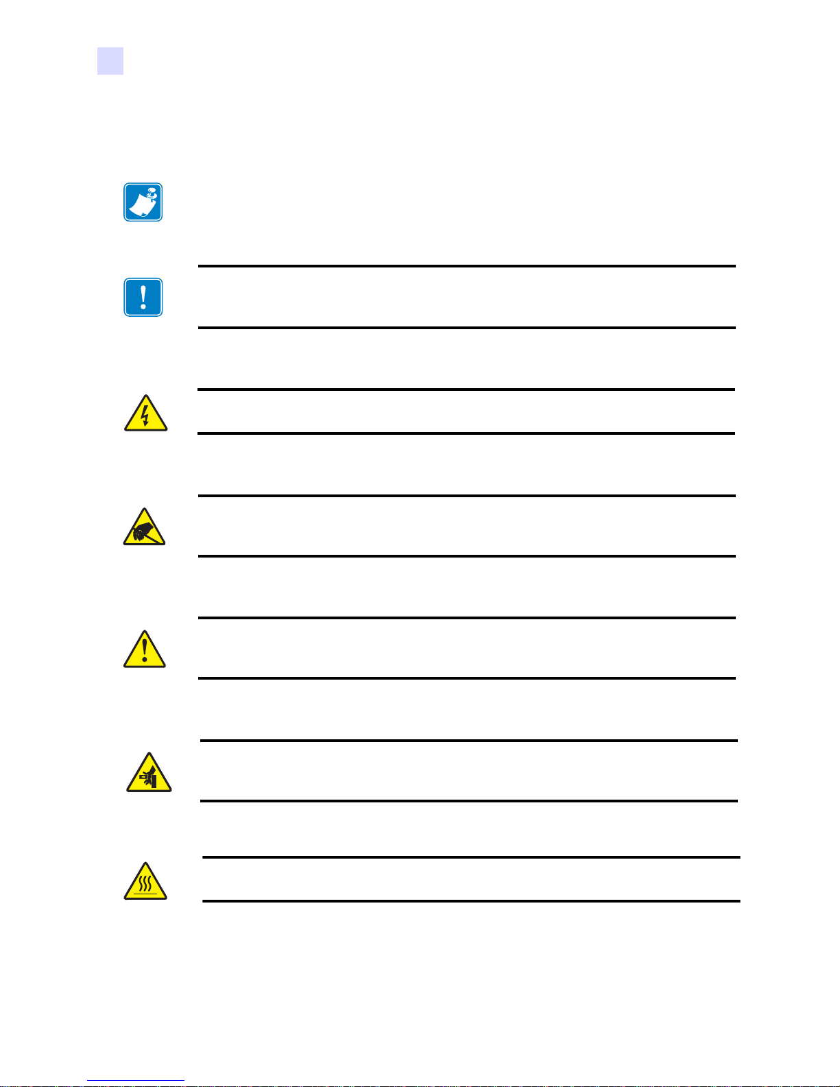
The following figure shows features of the P630i/P640i Printer.
Security
Key
(Optional)
Card
Feeder
Control
Panel
RibbonCleaning Cassette
Magnetic Encoder
(Optional)
Ribbon Take-Up Spool
Print
Head
Flip Station
Output
Hopper
Laminator Station (P640i)
Laminator Station (P630i)
Power Switch
2 P630i, P640i Card Printer User’s Manual 980541-003 Rev. A
AC Power Connector
Page 15
Controls and Indicators
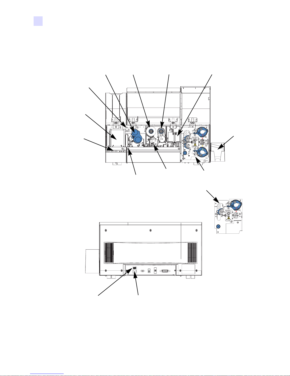
Control Panel Buttons
A limited amount of control and status information is available at the Control Panel on the
front of the printer. Additional control functions and status information is available via the host
or networked computer(s).
Introduction
Controls and Indicators
Buttons
PRINT Button
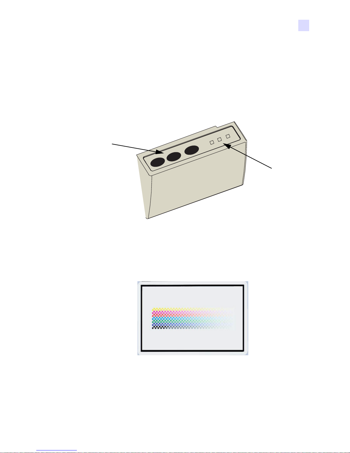
Press the PRINT button to print the image stored in the printer’s me mory. When the printer is
powered up, the memory is loaded with a checkerboard test pattern.
PRINT
RIBBON
LAMINATE
READY
ALARM
EDIA
M
Indicators
In regular on-line use, the PRINT button reprints the last image downloade d from the
computer to the buffer memory . If you hold the PRINT button down and powe r up the pri nter,
the Ribbon Syncronization feature (which no rmally force s a ribbon synchroni zation wh enever
the door is closed or the printer is powered up) is disabled.
980541-003 Rev. A P630i, P640i Card Printer User’s Manual 3
Page 16

Introduction
Controls and Indicators
If you press and hold the PRINT button for more than two seconds, the printer will
continuously reprint the image in the buffer. Stop this action by pressing the button
momentarily while printing is in proces
Note that pressing the PRINT button will have no effect if any of the following applies:
• An error condition exists
• You have set up the print driver to print color on both sides of the card
• The optional hardware lockout key, ID/Key, is missing (but this does not disable the
checkerboard printout available after power-up).
RIBBON button
This button is used to synchronize the ribbon – in other words, to position it correctly under
the print head. If you hold the RIBBON button down and power up the printer, it toggles on/
off the Ribbon Syncronization feature when the door is closed.
In typical applications, the ribbon type is YMCK, and the back of the card is printed first. In
such cases, pressing the RIBBON button will advance the color ribbon to bring the leading
edge of the next black panel under the print head.
If back side printing is not enabl ed, the p rinter will synchronize on the n ext yello w panel when
the RIBBON button is pressed.
LAMINATE button
(For the P640i Printer, this applies to the Upper and Lower Laminator; the P630i Printer has
only the Upper Laminator.)
If either (or both) of the laminate transfer rollers is not loaded with a laminate patch, then
pressing the LAMINATE button will correct the condition , p r ov id ed the cassette is not out of
laminate, and if the cassette latch is closed (locked). If both transfer rollers are already loaded,
the LAMINATE button has no effect. If you hold the LAMINATE button down and power
up the printer, it toggles on/off the Ribbon Syncronization feature when the printer is powered
up.
A typical use of the LAMINATE button is in reloading a transfer roller after removing the
first hand-cut patch of laminate following installation of a fresh roll.
4 P630i, P640i Card Printer User’s Manual 980541-003 Rev. A
Page 17
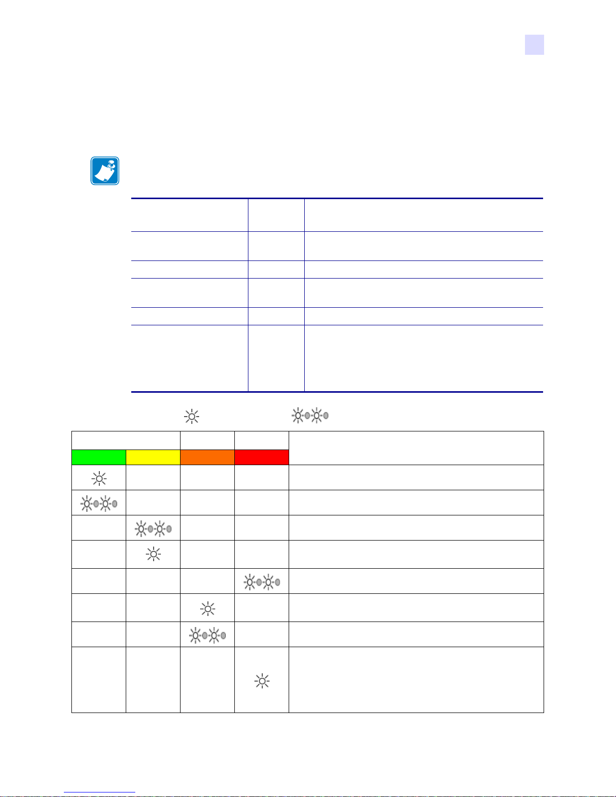
Control Panel Indicators
Depending on the condition they are reporting, the three indicator lights, READY, MEDIA,
and ALARM, can be in one of three states: Off, On (steady), or Flashing.
Note • The READY indicator is bi-colored. Its two color channels, green and yellow,
function independently.
READY Indicator Green: Steady = Ready to print
Introduction
Controls and Indicators
Flashing = Printer busy
Yellow:
MEDIA Indicator Off: Normal
On:
ALARM Indicator Off: Normal
On:
= LIGHT ON
READY MEDIA ALARM
GREEN YELLOW ORANGE RED
Steady = Laminator(s) in sleep mode
Flashing = Laminator(s) not at operating temperature
Steady = Any media outage
Flashing = Magnetic encoding failure
Steady = Error condition requiring intervention
Flashing = Printhead temperature error, or major
internal control problem requiring power cycling of
the printer (OFF, pause, then ON)
= LIGHT FLASHING
PRINTER STATUS
Ready to print
Printer busy
Laminator heating up, but not yet at operat in g t empe ra tu re
980541-003 Rev. A P630i, P640i Card Printer User’s Manual 5
Laminator heaters in sleep mode (when not in use, the
o
heaters cool at 1
F per minute)
Printhead temperature error, or internal firmware problem.
No cards in hopper, color ribbon out, cleaning tape out,
laminator cassette(s) out.
Magnetic encoding write failure
Serious error conditions, including: Main cover open,
Laminator too hot, card transport stalled, card not seated
properly, magnetic encoding verification error, head lift
failure, ribbon jam, card jam (any location), card missing
(any location), no gap between laminator patches.
Page 18
Introduction
Controls and Indicators
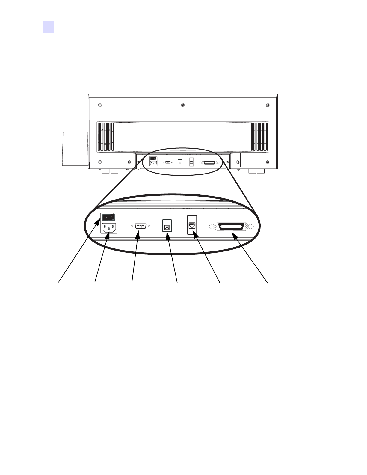
Rear of Printer
The Power Connector, Power Switch, and Int erface Connect or(s) are located on t he rear of the
printer, as shown below.
Power
Switch
6 P630i, P640i Card Printer User’s Manual 980541-003 Rev. A
AC Power
Connector
DB9 Serial Interface
Connector for Contact
Smart Card Contact
Station (Optional)
USB
Connector
Ethernet
Connector
(Optional)
Parallel
Connector
(Optional)
Page 19

Introduction
Installation includes setting up the printer, installing the printer driver in the computer(s) that
will be sending print jobs to the printer, connecting the interface, installing the Cleaning
Cartridge, loading the cards, ribbon, and laminate, and verifying that the printer can print a test
card.
2
Installation
Loading the Printer Driver software is described in Section 3.
Installation Procedure
Important • Execute the procedures that follow in the order given.
Remove the Printer from the Shipping Carton
Step 1. Open and remove the plastic handle/latches on either end of the shipping carton.
Step 2. Lift the upper part of the shipping carton off the lower part.
980541-003 Rev. A P630i, P640i Card Printer User’s Manual 7
Page 20
Installation
Installation Procedure
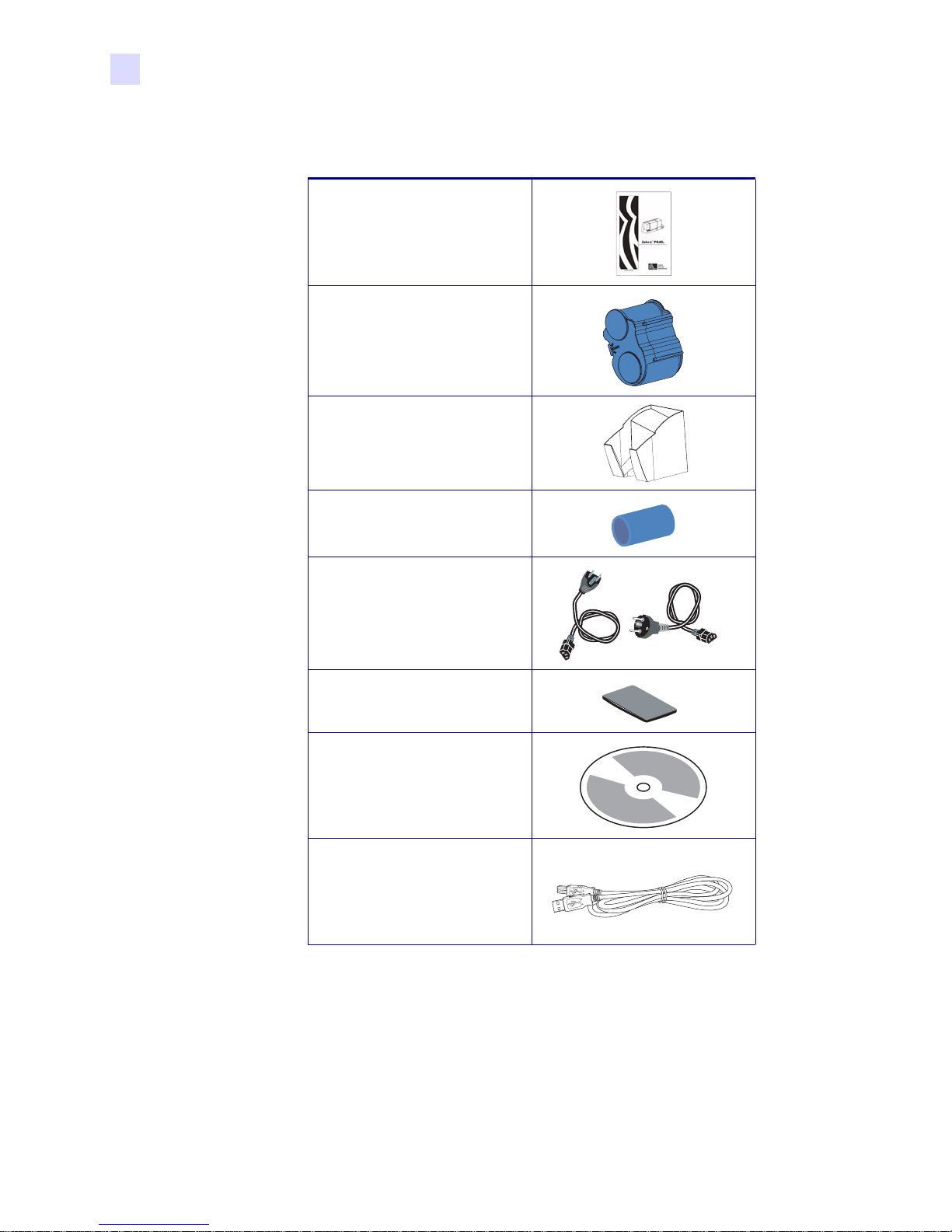
Step 3. Remove the items from the cutouts in the foam block atop the printer. Verify that the
following items are included:
Printed Quick-St art Guide
Cleaning Cartridge
Output Hopper
Ribbon Take-up Spool
Two Power Cords
Card Weight
Documentation & Driver CD
USB Interface Cable
8 P630i, P640i Card Printer User’s Manual 980541-003 Rev. A
Page 21
Installation
Installation Procedure
Step 4. Remove the foam block from the top of the shipping carton.
Step 5. Lift the printer from the shipping carton.
Caution • The printer weighs approximately 15.9 kg (35 lbs).
Step 6. Remove the protective plastic bag from the printer.
Important • Save all the packing material and the shipping carton in case the print er needs to
be moved or shipped. If the original material is lost or damaged, a replacement Shipping Kit
can be ordered from Zebra.
Step 7. Place the printer in a location that meets the following requirements:
• A reasonably dust- and dirt-free environment will give better print quality.
• Flat surface at least 699 mm (27.5 in) x 246 mm (9.7 in) that can support the weight of the
printer; additional space preferred. Vertical clearance at least 450 mm (17 in). There
should be easy access to all sides of the printer.
• Temperature within the range of 10° to 35°C (50° to 95°F).
• Relative Humidity 20 to 80%, non-condensing.
• AC power accessible.
980541-003 Rev. A P630i, P640i Card Printer User’s Manual 9
Page 22
Installation
Installation Procedure
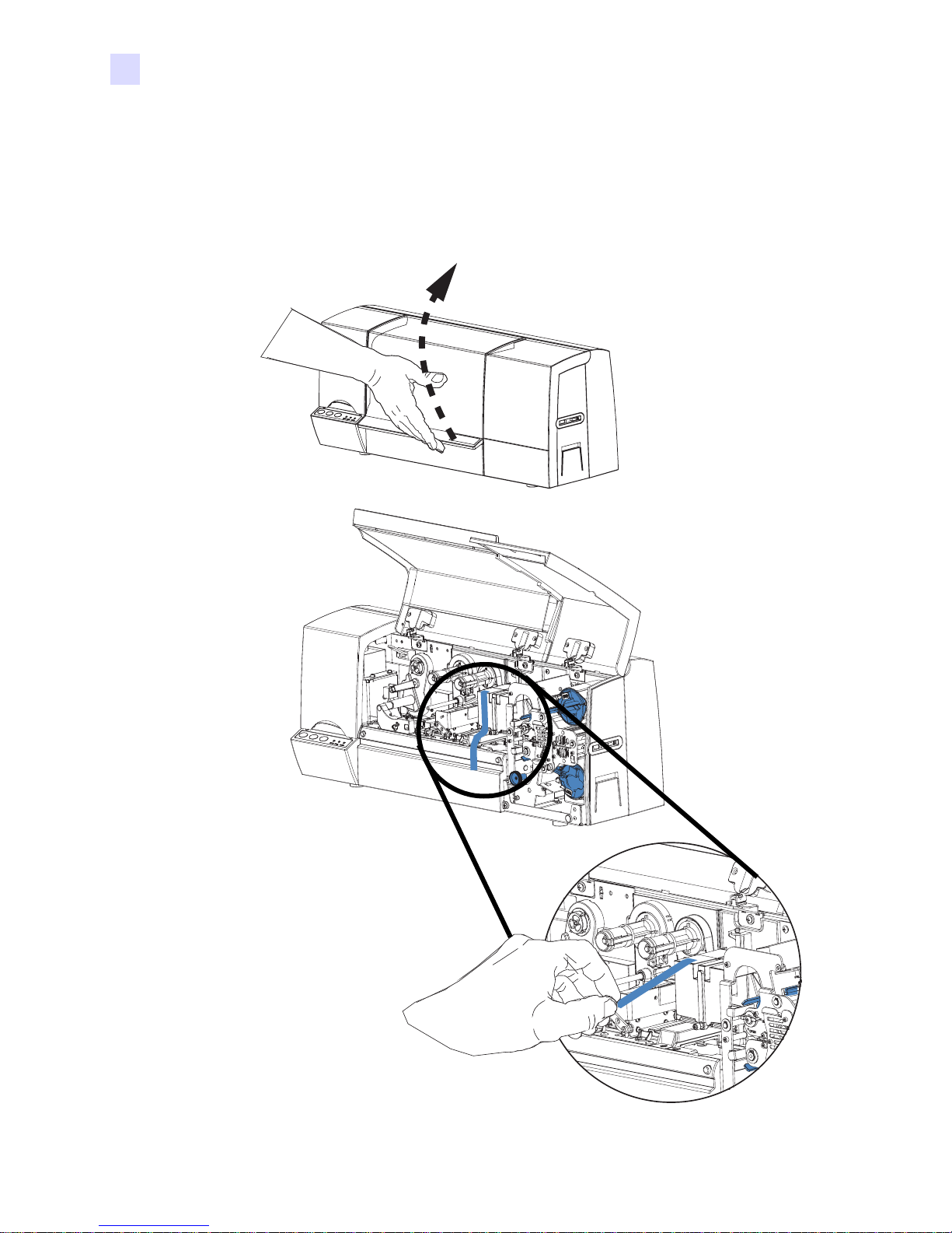
Remove Shipping Tape
Step 1. Open the printer Main Co ver. Locate and remove the blue tape that secures the flip
station in position.
10 P630i, P640i Card Printer User’s Manual 980541-003 Rev. A
Page 23
Attach the Output Hopper
Step 1. The Output Hopper is positioned on the right side of the printer to receive the printed
cards. Install the Output Hopper by in serting the tab on the si de of the Output Hopp er
into the slot on the right side of the printer.
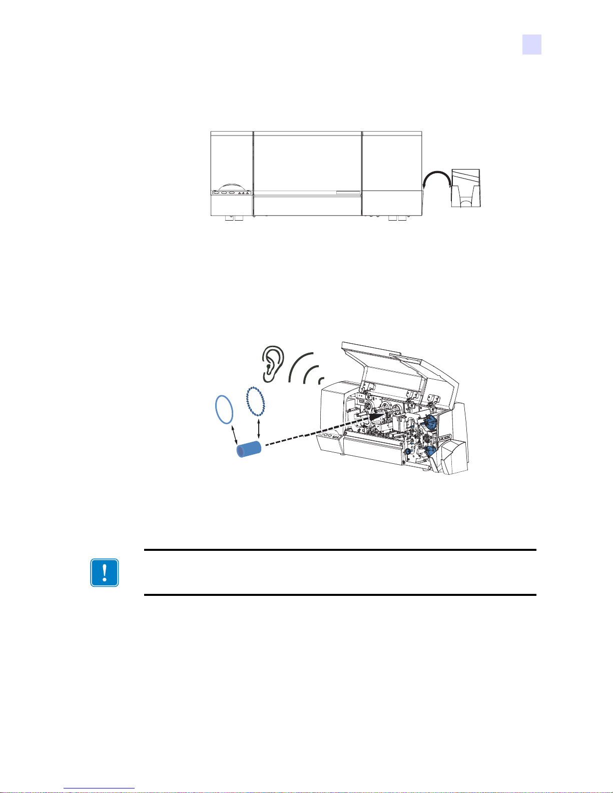
Attach the Ribbon Take-Up Spool
Installation
Installation Procedure
Step 1. Attach the Ribbon T ake-Up Spool by sliding it onto the Ribbo n Take-Up Spindle and
pressing it straight back until in clicks into place.
Important • Make sure that the Ribbon Take-Up Spool is attached with its “toothed” end
toward the rear of the printer.
980541-003 Rev. A P630i, P640i Card Printer User’s Manual 11
Page 24
Installation
Installation Procedure
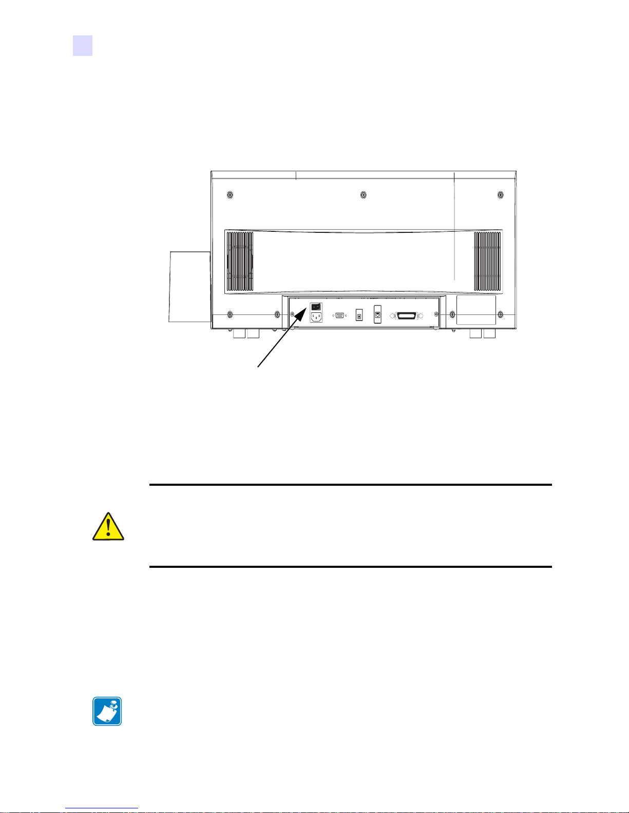
Connecting Power
The AC Power is connected and turned on so that in the next procedure, Ribbon Installation,
when the printer’s main cover is opened the Print Head will raise automatically.
Step 1. Verify that the printer’s Power Switch is set to OFF (O).
Step 2. Select the proper power cord for the local ac power source from the accessories that
are shipped with the printer.
Caution • If you do not have the proper power cord for your local power source, or if the
power cord appears frayed or damaged in any way, or if the power cord will not securely
plug into the printer’s power connection or the source outlet, STOP! Use of a damaged or
incorrect power cord could cause equipment damage, result in an electrical fire, or
possibly cause injury.
Step 3. Plug the power cord into the printer’s power connection and a grounded AC power
source connection.
Step 4. Turn the printer on by setting the Power Switch to ON (I).
Ribbon Installation
Power Switch
Note • In normal printer operation, when the ribbon is exhausted, a warning message appears
on the monitor and the MEDIA indicator on the printer lights.
12 P630i, P640i Card Printer User’s Manual 980541-003 Rev. A
Page 25
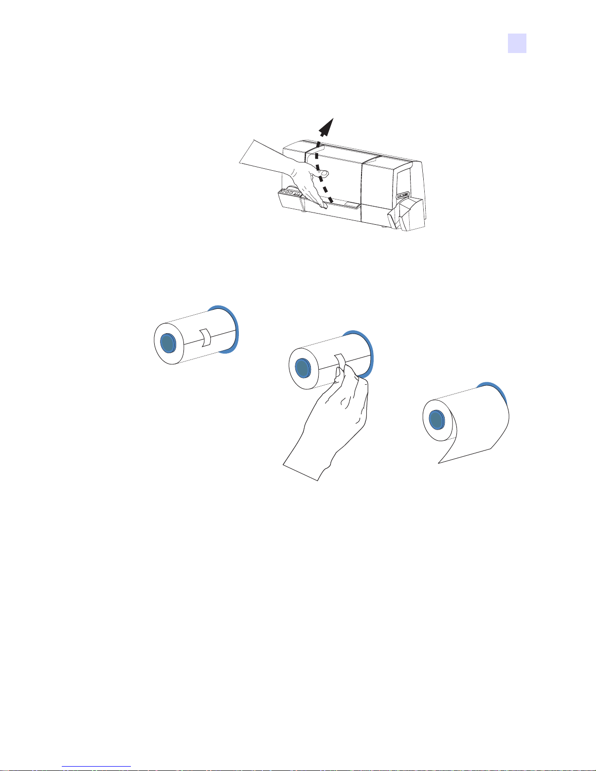
Installation
Installation Procedure
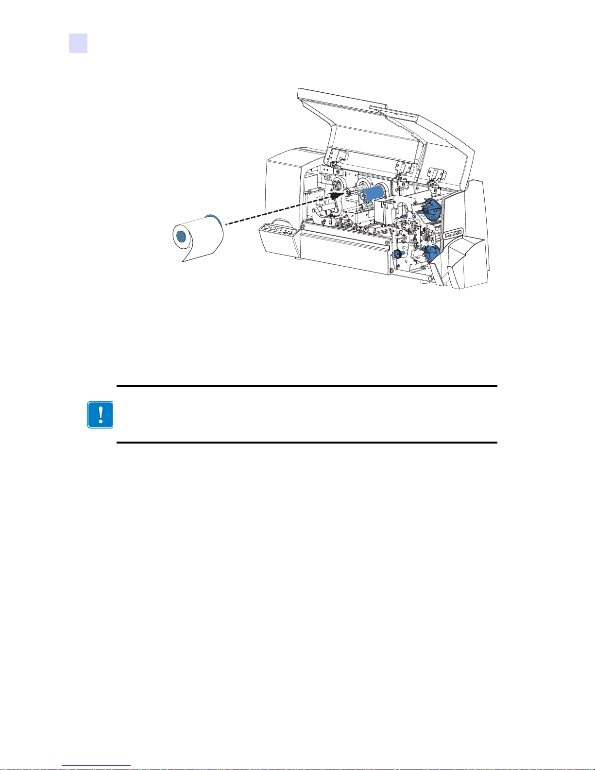
Step 1. Open the printer Main Cover. The printhead will raise for easy ribbon loading.
Step 2. Remove the ribbon from its packaging. Remove the tape that holds the end of the
ribbon (save this tape; it will be used shortly).
Step 3. Install the Ribbon on the left (supply) spindle, with the free end of the ribbon coming
from the roll pointing down to your right. Note that the “flanged” end of the ribbon
spool is toward the rear of the printer, and make sure the internal grooves on the core
engage the teeth on the supply spindle.
980541-003 Rev. A P630i, P640i Card Printer User’s Manual 13
Page 26
Installation
Installation Procedure
Step 4. Route the Ribbon as shown in the figure below. The Ribbon Supply Spindle is free-
wheeling; pull ribbon off it as needed. If the tape removed from the new ribbon in
step 2 is undamaged, use it to attach the end of the ribbon to the Take-Up Spool;
otherwise use other adhesive-backed tape.
Important • When the end of the ribbon is attached to the Take-Up Spool, any slack in the
ribbon can be taken up by rotating the Ribbon Supply Spool; do not try to turn the Take-Up
Spool
14 P630i, P640i Card Printer User’s Manual 980541-003 Rev. A
Page 27
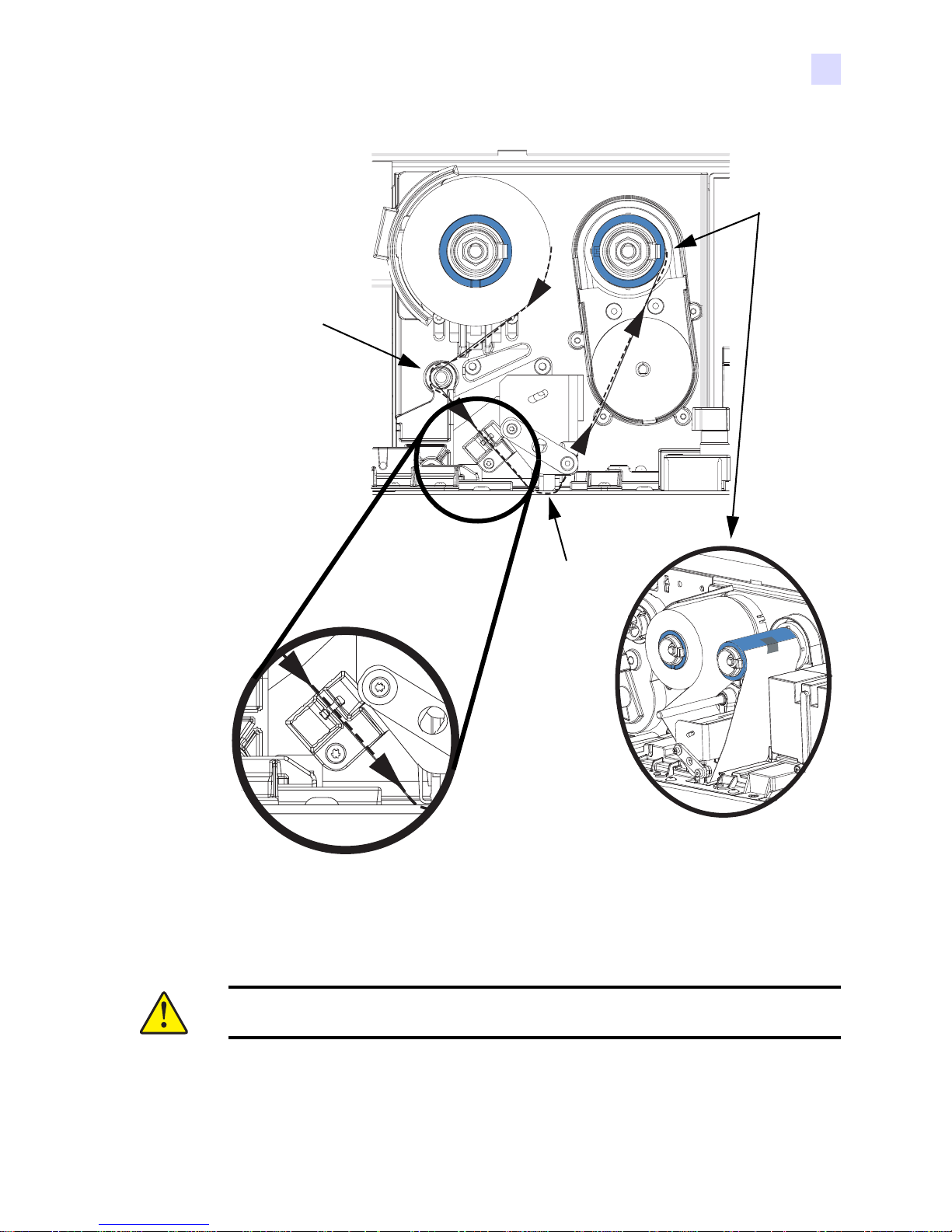
1. Pass Ribbon
Over the
Round
Guide Bar
Installation
Installation Procedure
4. Attach
Ribbon to
Take-Up
Spool
With Tape
2. Ribbon Goes
Through the
Ribbon
Sensor
3. Ribbon
Goes
Under
the
Print
Head
Step 5. Close the printer main cover, then press the RIBBON button on the Control Panel.to
initialize the color ribbon. If the MEDIA light fails to go out, check the ribbon
sensor.
Important • Color ribbon wrinkling and “fold-over” can seriously affect print quality
980541-003 Rev. A P630i, P640i Card Printer User’s Manual 15
Page 28
Installation
Installation Procedure
Step 6. Re-open the printer cover to inspect the ribbon path fo r wrinkles and folds. Correct if
necessary, then close the cover. If you do not then hear the ribbon motor advancing
the ribbon, press the RIBBON button.
Installing the Cleaning Cassette
Before being printed, each surface of the card is cleaned by a soft tacky roller that is itself
cleaned periodically by adhesive tape in the Cleaning Cassette. Typically, the roller is cleaned
every 10 cards. The printer driver software allows the card count to be modified.
By cleaning the roller every 10 cards, the Cleaning Cassette contains sufficient tape
for 3,000 cards. This matches the other components of the standard Zebra media pack
(3,000 cards, 3,000 color ribbon images).
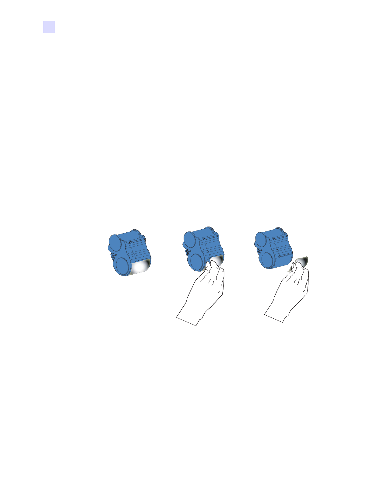
Step 1. Open the main cover of the printer.
Step 2. Remove the Cleaning Cassette from its packaging.
Step 3. Remove the protective foil from the Cleaning Cassette. Avoid touching the exposed
tacky surface.
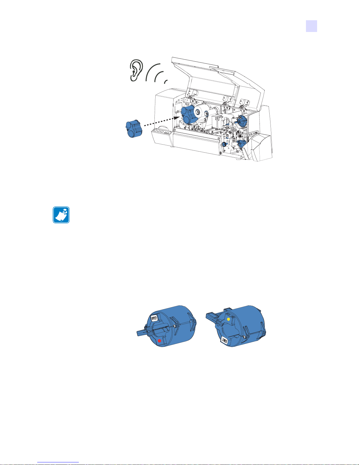
Step 4. Install the Cleaning Cassette on the printer by locating the rectangular pin on the
cleaning mechanism in the receptacle on the cassette. Push the cassette gent ly home,
ensuring that the internal grooves on the upper spool engage the teeth on the takeup
drive; you will hear a click when it is fully engaged.
16 P630i, P640i Card Printer User’s Manual 980541-003 Rev. A
Page 29
Loading Laminate
Installation
Installation Procedure
Note • In this description of loading laminate, references to the lower Laminate Cassette
apply only to the P640i Printer. The P640i Printer can apply laminate to both surfaces of the
card; the P630i Printer only to the upper surface.
The Laminate (laminating film) is loaded into cassettes to protect it from dirt or other
contaminants.
See the figure below. The “Upper Laminate Cassette”, used on both the P630i and P640i
Printers, has a label with the word “UPPER” and another “label” of a red dot. The “Lower
Laminate Cassette”, used only on the P640i Printer, has a label with the word “LOWER” and
another “label” of a yellow dot.
“Upper
Laminate
Cassette”
(P630i and
P640i)
Removing the Laminate Cassette(s)
“Lower
Laminate
Cassette”
(P640i only)
Step 1. The Laminate Cassette(s) (Upper only for the P630i Printer; Upper and Lower for the
P640i) are held in position by latch plates. The Upper Cassette is freed by turning its
Latch Plate counter-clockwise to a full vertical position; the Lower Cassette (only
present on the P640i Printer) is freed by turning its Latch Plate clockwise. Then pull
the cassette straight out from its holder.
980541-003 Rev. A P630i, P640i Card Printer User’s Manual 17
Page 30

Installation
Installation Procedure
Upper Laminate
Cassette Latch Plate
(P630i and P640i)
Heater
Cores
area
Lower Laminate
Cassette Latch Plate
(P640i only)
Hot Surface • If the printer has been in use, the Heater Cores area of the Laminator
may be hot.
Important • If either Latch Plate is opened, even unintentionally, the corresponding Cassette
must be removed and the Laminate reeled in.
18 P630i, P640i Card Printer User’s Manual 980541-003 Rev. A
Page 31

Installation
Installation Procedure
Caution • If you feel resistance when removing the cassette, the laminate has likely run
out, leaving one end attached to the core and the other end under the cutter. Keep
tugging on the cassette, which will come free with a short tail of laminate.
Step 2. Temporarily remove the corresponding Transfer Guide to be sure there are no scraps
of laminate remaining. If there are any, remove them. Then slide the Transfer Guide
back in until it is held in place by the Retaining Clip.
1. Push the
Retaining
Clips (A) to
the Left
2. Slide the
Transfer
Guides (B)
Straight Out
(B)
(A)
(A)
(B)
Step 3. Open the Cassette, like a clam shell, by separating its two halves. Grasp the two
halves firmly with your fingers, then pull it apart. Do NOT use tools. (Upper
Cassette shown.)
980541-003 Rev. A P630i, P640i Card Printer User’s Manual 19
Page 32

Installation
Installation Procedure
Step 4. If there is an empty laminate core in the Cassette, remove it.
Loading the Laminate Cassette(s)
uently
Important • If you are using partial-width laminate in the Lower Cassett e of a P640i Printer,
read the following section, Using Partial-Width Laminate, before proceeding with this
procedure. (Partial-width laminates are frequently used on the bottom surface of cards that
have a signature panel or a magnetic stripe.)
Important • The Upper and Lower La minate Cassettes (the low er one only used on th e P640i
Printer; the upper one used on both printers) are loaded diff erently, even though the Casset tes
appear virtually the same.
Note • Handle the laminate by the ends of the spools only to avoid contaminating the
laminate.
Step 1. Remove the new roll of laminate from its packaging.
Step 2. Carefully following the guidelines in the following figure, place the laminate in the
Cassette.
20 P630i, P640i Card Printer User’s Manual 980541-003 Rev. A
Page 33

.
Notched End of
Spool to Left
Laminate Unrolls
Under Spool
Laminate Unrolls
Over Spool
Installation
Installation Procedure
Upper Cassette
(Used on Both P630i and P640i)
White Roller Up
Notched End of
Spool to Right
White Roller Down
Lower Cassette
(Used on P640i Only)
Step 3. Pull out an inch or two of laminate past the lip of the cassette.
Step 4. Close the cassette by firmly pressing the “clamshell” together. You will hear a click
and feel a detent when the halves of the cassette seat together.
Step 5. Pull out a little more laminate between the lips of the cassette. If it suddenly stops,
resisting further pulling, a spring detent on the cassette has probably snagged a notch
on the end of the core. This means that the core was installed the wrong way. Open
the cassette and re-install the laminate.
Step 6. If the exposed end of the laminate is uneven or crinkled, cut it as square as you can
with scissors.
980541-003 Rev. A P630i, P640i Card Printer User’s Manual 21
Page 34

Installation
Installation Procedure
Step 7. Holding the cassette with the white roller up and pointing to your left, rotate the core
counter-clockwise to reel in the laminate. Stop when the end of the laminate is even
with the edge of the lips of the cassette.
Important • Check for overhang any time the cassette latch is opened or the cassette is
removed.
Using Partial-Width Laminate
Note • Since partial-width laminates are only used for the back (i.e., lower) surface of the
card, this section only applies to the P640i Printer.
Laminate come in three widths:
“Full-Width” laminate is 2 in (51 mm) wide. Full-width laminate is used on the front (i.e.,
upper) or back (i.e., lower) surface of the card.
“Partial-Width” laminate is available in two widths:
• 1.66 in (42mm) wide laminate is used for cards with a writable signature panel.
• 1.33 in (33 mm) wide laminate is used for cards with a magnetic stripe
If there is no signature panel or magnetic stripe on the back of the card, full-width laminate
would generally be used.
22 P630i, P640i Card Printer User’s Manual 980541-003 Rev. A
Page 35

These are shown in the following figure.
Installation
Installation Procedure
2“
1.66“
BACK OF CARD
1.3”
Step 1. Remove the Laminate Edge Guide from its “storage location” on the Laminator
Frame (it snaps out).
Laminate
Edge
Guide
Step 2. For 1.3 in (33 mm) laminate for use with magnetic stripe cards, snap the Laminate
Edge Guide into the inner hole-and-slot in the lower cassette, as shown in the
following pictures. For 1.66 in (42 mm) laminate for use with signature-stripe cards,
use the outer hole-and-slot.
980541-003 Rev. A P630i, P640i Card Printer User’s Manual 23
Page 36

Installation
Installation Procedure
Inner Holeand-Slot
Outer Holeand-Slot
Laminate Edge
Guide in Inner
Hole-and-Slot
for 1.33 in (33
mm) Laminate
Used With
Magnetic Stripe
Cards
Installing the Laminator Cassette(s)
Step 1. Insert the cassette into its black molded pocket, then close the cassette latch
(clockwise for the UPPER, counterclockwise for the LOWER).
1.33 in
(33 mm)
Laminate
for
Magnetic
Stripe
Cards
24 P630i, P640i Card Printer User’s Manual 980541-003 Rev. A
Page 37

Step 2. Close the main cover. If there was a laminate error before you replaced the cassette,
laminate will automatically feed from the just-loaded cassette, followed by a cutting
action to free a “patch” of laminate onto the transfer roller. If laminate does not feed
automatically, press the LAMINATE button on the printer control panel.
Clearing the Laminate Channels
If your scissor cuts were neat enough to pass for machine-made cuts, continue with printing
cards. If not, don’t waste a print cycle. Instead, remove the hand-cut patch(es) from the
Transfer Roller(s) as follows.
Note • Clearing procedures for the upper and lower laminate channels are similar. The upper
channel is shown here.
Removal of the Transfer Guide gives access to the Transfer Roller
Installation
Installation Procedure
Retaining
Springs
Transfer
Guides
Transfer Toggle
(Shown in Normal
RUN Position; Set
to OPEN Only
When Specified)
OPEN
RUN
Step 1. Push the Retaining Spring to the left; pull the T ransfer Guide straig ht out toward yo u.
Step 2. Remove and discard the laminate patch on the Transfer Roller. Never re-use!
Step 3. Turn the Transfer Toggle to the OPEN position.
Step 4. Remove any laminate between the Transfer Rollers.
Step 5. Return the Transfer Toggle to the RUN position.
980541-003 Rev. A P630i, P640i Card Printer User’s Manual 25
Page 38

Installation
Installation Procedure
Step 6. Re-install the Transfer Guide with its top edge above the laminate cutter guide. Pull
Important • Improper replacement of the Transfer Guide can cause laminate skewing
and misfeeding. Be sure the Transfer Toggle is set to RUN. Take care to avoid damaging
the Transfer Roller ribs when replacing the Transfer Guide.
Loading Cards
The P630i and P640i Printers use standard ISO CR-80 PVC Composite cards. Do not use
cards with a paper or peel-off / adhesive backing.
• Size 54 x 86 mm (2.125 x 3.375 in) ± 10%
back the retaining spring while re-inserting the guide, then release the spring as you
push the guide into position. Press the LAMINATE button to load the Transfer
Roller(s).
• Thickness .75 mm (.03 in) ± 10%, frequently referred to as “30 mil cards”.
Important • Do not bend card s or touch the print surfaces a s this can reduce print quality. The
surface of the cards must remain clean and dust free. Always store cards in an enclosed
container. Ideally, use cards as soon as possible.
Step 1. Open the Card Feeder Cover.
26 P630i, P640i Card Printer User’s Manual 980541-003 Rev. A
Page 39

Installation
Installation Procedure
Step 2. Remove all wrapping from the card deck.
Caution • Do not touch print surfaces of the cards; this can reduce print quality.
Step 3. Holding the card deck by the sides, hold it vertically against a flat surface such as a
desktop. If the deck is too thick for your hand to hold it comfortably, use about half a
deck at a time.
Step 4. Push the stack back and forth to an angle of about 45° from vertical, so as to separat e
all of the cards.
Important • Static charges and edge burrs from the card die-cutting process can render
individual cards stuck together with significant adhesion force. These cards must
be
physically separated from each other before inserting into the Card Feeder; if not separated,
feeding or printing problems may occur.
Step 5. Restore the card stack to its original squared-of f condition, and place the cards in the
input hopper. The input hopper can hold up to 150 cards.
Note • Cards with a Magnetic Stripe should be loaded with the stripe up and toward the front
of the printer, as shown in the figure below.
980541-003 Rev. A P630i, P640i Card Printer User’s Manual 27
Page 40

Installation
Installation Procedure
Step 6. Place the Card Weight on top of the card stack.
Step 7. Close the Card Feeder Cover.
28 P630i, P640i Card Printer User’s Manual 980541-003 Rev. A
Page 41

Connecting the Interface
The P630i and P640i Printers have a USB interface as standard. As options (must be specified
at time of order), the printer can addi tionally have a 10/100T Ethernet port for connection to an
Ethernet Network, or a parallel (“Centronics”) port. Normally only one interface at a time will
be connected.
Installation
Installation Procedure
980541-003 Rev. A P630i, P640i Card Printer User’s Manual 29
USB
Connector
Ethernet
Connector
(Optional)
Parallel
Connector
(Optional)
Page 42

Installation
Installation Procedure
30 P630i, P640i Card Printer User’s Manual 980541-003 Rev. A
Page 43

Printer Driver Installation
Overview
3
Each computer that will use the P630i or P640i Printer must have the Printer Driver installed.
A common Printer Driver serves both P630i and P640i Printers.
To install the Printer Driver, insert the User Documentation, Drivers, and Training CD,
included with your printer, into the host computer and the InstallShield Wizard will walk you
through the required installation steps. The InstallShield Wizard will:
• Automatically install the User Interface when the driver CD is inserted.
• Start the installation process when the Install Printer Driver menu item is selected
from the Main Menu.
• Allow you to install either a local printer and driver or a networked printer and driver.
• Detect previous versions of the driver and clean up any unnecessary Windows registry
entries. You must select Uninstall Printers and Drivers in the Printer Setup window
to remove any previous driver versions.
• Install the new driver files
• Reboot your computer
980541-003 Rev. A P630i, P640i Card Printer User’s Manual 31
Page 44

Printer Driver Installation
Installing the Printer Driver (USB)
Installing the Printer Driver (USB)
Note • To install the Ethernet driver, see the procedure starting on page 41.
Step 1. Connect the printer power and connect the USB port on the rear of the printer to the
computer’s USB port. Turn the Printer on and let it initialize until the READY LED
on the front panel is lit.
Step 2. The Windows “Found New Hardware” screen will appear at this time. Click
“Cancel”.
Step 3. Insert the User Documentation, Drivers, and Training CD into the CD drive of the
host computer. The Select Language window will open.
Step 4. From the Select Language window, choose the appropriate language for your
system. The Main Menu will open in the selected language (English shown below).
32 P630i, P640i Card Printer User’s Manual 980541-003 Rev. A
Page 45

Printer Driver Installation
Installing the Printer Driver (USB)
Step 5. From the Main Menu, click Install Printer Driver. The Printer Setup window will
open.
980541-003 Rev. A P630i, P640i Card Printer User’s Manual 33
Page 46

Printer Driver Installation
Installing the Printer Driver (USB)
Step 6. If an older P630i or P640i Printer and Driver is installed on your computer, click on
Uninstall Printers and Drivers to remove it. Follow the screen prompts. At the end
of the uninstall process you will be asked to re-boot your computer. Before rebooting, exit from the Driver Installation program and remove the CD. Then re-boot
your computer and start over with Step 1. If the computer enters the Found New
Hardware Wizard at this time, cancel this wizard.
Click on Install a USB or Parallel Printer and Driver.
34 P630i, P640i Card Printer User’s Manual 980541-003 Rev. A
Page 47

Printer Driver Installation
Installing the Printer Driver (USB)
Step 7. This will bring up the End User License Agreement. To proceed with the
installatiion, click Accept.
Step 8. This will bring up the Add Zebra Printer Port window. Select the USB Port, and
then click Next >>.
980541-003 Rev. A P630i, P640i Card Printer User’s Manual 35
Page 48

Printer Driver Installation
Installing the Printer Driver (USB)
Step 9. This brings up the Browse Printers window, shown below. If your P640i / P630i
Printer is listed, select (highlight) it and click OK.
If your printer is not listed, make sure the printer is powered on and check the USB
cable connections; then click Rescan. When it appears, select (highlight) it and click
OK.
Step 10. This brings up the Configure USB Port window. If your printer is not listed in the
Printer info area, click Browse.
Leave the two timeout values alone. Click OK.
Step 11. This will bring up the Printer Installation window. Note the value shown on the first
line (ATLUSB001 for the screen shown here), then click OK.
36 P630i, P640i Card Printer User’s Manual 980541-003 Rev. A
Page 49

Printer Driver Installation
Installing the Printer Driver (USB)
Step 12. This opens the Add Printer Wizard welcome window. Click Next >.
Step 13. This brings up the Add Printer Wizard Local or Network Printer window. For a
typical USB installation, select Local Printer attached to this computer and check
the box to detect a Plug and Play printer.
Then click Next >.
980541-003 Rev. A P630i, P640i Card Printer User’s Manual 37
Page 50

Printer Driver Installation
Installing the Printer Driver (USB)
Step 14. This brings up the Found New Hardware Wizard welcome window. In general, select
Yes, this time only and then click Next >.
Step 15. The next window helps install the software driver. Select Install the software
automatically (Recommended) and then click Next >.
Step 16. The Wizard will search for the Printer. The screen that appears while searching
appears on the next page.
38 P630i, P640i Card Printer User’s Manual 980541-003 Rev. A
Page 51

Printer Driver Installation
Installing the Printer Driver (USB)
Step 17. When the Wizard finds the Printer, it may display a window referring to
compatibility, as shown below. If so, click Continue Anyway.
980541-003 Rev. A P630i, P640i Card Printer User’s Manual 39
Page 52

Printer Driver Installation
Installing the Printer Driver (USB)
Wait while the Wizard installs the software.
Step 18. When software installation is complete, the following window will display. Click
Finish.
Step 19. This completes software driver installation. To use the P630i or P640i Printer, you
would select it just like you would any other printer connected to a Windows system.
40 P630i, P640i Card Printer User’s Manual 980541-003 Rev. A
Page 53

Installing the Printer Driver (Ethernet)
Note • To install the USB driver, see the procedure starting on page 32.
Important • The Ethernet Network must be configured correctly, with the Printer and the host
computer on the same subnet mask. If you are not sure how to verify this or change the
configuration, consult someone knowledgeable on Ethernet Networks.
Step 1. Connect the printer power and connect the Ethernet Port on the rear of the printer to
an Ethernet Network Port. Turn the Printer on and let it initialize until the READY
LED on the front panel is lit.
Step 2. Insert the User Documentation, Drivers, and Training CD into the CD drive of the
host computer. The Select Language window will open.
Printer Driver Installation
Installing the Printer Driver (Ethernet)
Step 3. From the Select Language window, click on the appropriate language for your
system. The Main Menu will open in the selected language (English shown below).
980541-003 Rev. A P630i, P640i Card Printer User’s Manual 41
Page 54

Printer Driver Installation
Installing the Printer Driver (Ethernet)
Step 4. From the Main Menu, click Install Printer Driver. The Printer Setup window will
open. Click Install an Ethernet Printer and Driver.
42 P630i, P640i Card Printer User’s Manual 980541-003 Rev. A
Page 55

Printer Driver Installation
Installing the Printer Driver (Ethernet)
Step 5. This will bring up the End User License Agreement. To proceed with the installation,
click Accept.
Step 6. This brings up the Configure Ethernet Port screen. Click the Browse button.
980541-003 Rev. A P630i, P640i Card Printer User’s Manual 43
Page 56

Printer Driver Installation
Installing the Printer Driver (Ethernet)
Step 7. Any Zebra printers will be located. Select (highlight) the desired printer (for this
procedure it is a P640i, but the steps would be the same for a P630i) and click the
OK button.
Note • If the Printer is not found, check to make sure the Printer is powered on and the
Ethernet connector is engaged. Also, the Ethernet Network must be configured correctly, with
the Printer and the host computer on the same subnet mask. If you are not sure how to verify
this or change the configuration, consult someone knowledgeable on Ethernet Networks.
Step 8. The Configure Ethernet Port screen will reappear, but now the information for the
P640i printer selected in step 7 will be displayed.
Then click OK.
44 P630i, P640i Card Printer User’s Manual 980541-003 Rev. A
Page 57

Printer Driver Installation
Installing the Printer Driver (Ethernet)
Step 9. This brings up the Add Printer Wizard. Click Next >.
Step 10. The next screen lets you specify the type of printer to set up. Select “Local printer
attached to the computer.”
“Automatically detect and install my Plug and Play printer” should be un-checked.
Then click Next >.
Click Next >.
980541-003 Rev. A P630i, P640i Card Printer User’s Manual 45
Page 58

Printer Driver Installation
Installing the Printer Driver (Ethernet)
Step 11. The Add Printer Wizard / Select a Printer Port screen will now appear.
Step 12. Click on “Use the following port”; scroll to “ENETxxx (Zebra Ethernet (internal))”
where “xxx” is the number of the port - any Zebra Ethernet port number can be used.
Check that the printer is turned on (and the READY LED is lit), then click Next >.
Then click Next >. This will bring up the “Add Printer Software Wizard”, as shown
on the next page.
46 P630i, P640i Card Printer User’s Manual 980541-003 Rev. A
Page 59

Printer Driver Installation
Installing the Printer Driver (Ethernet)
Select the Manufacturer (Zebra Technologies) and the printer model number; then
click Next >.
Step 13. This brings up the “Name Your Printer” screen.
Verify that the printer name is correct. Specify if you want to use this printer as your
default printer (this can always be changed in the Windows Printers or Printers and
FAXes control panel).
Then click Next >.
980541-003 Rev. A P630i, P640i Card Printer User’s Manual 47
Page 60

Printer Driver Installation
Installing the Printer Driver (Ethernet)
Step 14. Specify whether or not you want to allow printer sharing, then click Next >.
Step 15. Specify if you wish to print a test page (note that card printers consider each card to
be a page); then click Next >.
48 P630i, P640i Card Printer User’s Manual 980541-003 Rev. A
Page 61

Installing the Printer Driver (Ethernet)
Step 16. Click Finish. The following screen will appear.
Printer Driver Installation
Step 17. Click on Continue Anyway. You will see files being copied to the Windows folder.
When the file copying is complete, your printer is ready to use.
980541-003 Rev. A P630i, P640i Card Printer User’s Manual 49
Page 62

Printer Driver Installation
Installing the Printer Driver (Ethernet)
50 P630i, P640i Card Printer User’s Manual 980541-003 Rev. A
Page 63

Settings and Adjustments
Introduction
This section describes settings and adjustments that can be made to the P630i and P640i
Printers.
4
Sensors and Interlock Switches
These are of several different types of sensors and interlock switches, but they have one thing
in common - they tell the printer’s control logic what’s happening and where, enabling it to
continue with the process or, if a malfunction occurs, to light the appropriate indicator light
and report a specific error condition on the host computer screen.
The sensors and iterlocks are shown in the following figure.
980541-003 Rev. A P630i, P640i Card Printer User’s Manual 51
Page 64

Settings and Adjustments
Sensors and Interlock Switches
Card
Presence
Sensor
Truck
Near
Hopper
Interlock
Truck
Home
Sensor
Cover
Interlock
Cleaning
Sensor
Ribbon
Motion
Sensor
Ribbon Sensor
(Not Accessible)
Flip
Sensor
Printhead Motion Sensor
(Not Accessible)
Infeed
Sensor
Outfeed
Sensor
(Lower Laminator
Present on P640i Only)
Access Printer Sensor Data
To access the Sensor Data screen, select Start > Printers (or Printers and Faxes). Right click
Zebra P630i or Zebra P640i, then select Properties > Device Settings > Control > Advanced Utilities
> Show Sensor data.
52 P630i, P640i Card Printer User’s Manual 980541-003 Rev. A
Page 65

Settings and Adjustments
Sensors and Interlock Switches
Ribbon Panel Detect. The current reading of the color ribbon sensor.
Panel Threshold. The current value of the detection threshold for the color ribbon. Above
this value is termed “black,” below this value is termed “not black.”
Laminate Sensors. Reflective sensor that detect the presence of laminate on the transfer
rollers: below threshold = laminate present, above threshold = laminate absent.
Card presence Sensor. The reflective sensor to the right of the card hopper: High = no
card, Low = card present
Printhead Voltage. Should be about 24V.
AC Frequency. 50 or 60 Hz
Assumed AC Voltage. 110V assumed for 60 Hz.
Printhead Temperature. Temperature ceiling 70°C (above that temperature, printing is
stopped until the head cools).
Controller Board Temperature. Should be about 5° above ambient.
Heater Temperature. Temperatures at the top and bottom laminate heater cores.
Logic States. Summarizes all two-state interlocks and photo sensors - a very useful
diagnostic tool
980541-003 Rev. A P630i, P640i Card Printer User’s Manual 53
Page 66

Settings and Adjustments
Printer Properties
Printer Properties
To access the various Printer Properties, select Start > Printers (or Printers and Faxes). Right click
Zebra P630i or Zebra P640i, then select Properties
General
Printing Preferences Brings up the
preferences screen. Reference Printing
Preferences below.
Print Test Page Prints the standard
Windows test page.
Sharing
This is sharing according to the Microsoft
Windows definition. In a network
environment, it allows other computers to
send jobs to the printer that’s connected to
your computer.
54 P630i, P640i Card Printer User’s Manual 980541-003 Rev. A
Page 67

Ports
Settings and Adjustments
Printer Properties
Specifies the computer port to which the
P630i or P640i is connected. This will have
been established at the initial installation of
the printer, and will not normally require
attention.
An exception to this is if you wish to use
“printer pooling”, the ability to distribute
print jobs to multiple printers. To enable
printer pooling, check the “Enable Printer
Pooling” box, then check multiple ports.
Each port should have a single Zebra printer
installed on it, and all printers should be
configured identically (for example: all with
YMC front, K back). Now, when you print to
the “main printer” (that is, whichever printer
you right-clicked in Printers and Faxes to get
to this screen), this printer will get print jobs
until it has buffered as many jobs as it can
take. Remaining jobs will then “spill over” to
other printers until all printers in the pool are
busy.
Advanced
Determines the spooling (queuing) of print
jobs, and how spooled jobs are handled
relative to the most recent job. Printing
Defaults allows the system administrator to
establish default settings such as print
quality.
980541-003 Rev. A P630i, P640i Card Printer User’s Manual 55
Page 68

Settings and Adjustments
Printer Properties
Color Management
Color Management settings allow you to
associate color profiles on the printer based
on the type of media being used and printer
configuration. The Add button allows the
operator to add additional profiles to the
color profile list.
Automatic Allows Windows to select the
best color profile.
Manual Allows the operator to select the
desired profile from the list shown in the
Color Profile Window.
Security
This is the standard Windows security
screen, showing user access to various
printer control options. Both Print and
Manage Printers must be checked for full
functionality of the printer.
56 P630i, P640i Card Printer User’s Manual 980541-003 Rev. A
Page 69

Device Settings
Settings and Adjustments
Printer Properties
The Device Settings screen allows you to
access various adjustment and calibration
screens.
Printer Adjustment The following procedures can be performed from the Printer
Adjustment screen:
1. Print Station Adjustment
2. Laminate Station Adjustment
3. Flip Station adjustment
4. Advanced Adjustments:
a. Magnetic Encoder Position
b. Smart Card Position
5. Card Hopper Pick Position
6. Cleaning Frequency
980541-003 Rev. A P630i, P640i Card Printer User’s Manual 57
Page 70

Settings and Adjustments
Printer Properties
Color Calibration The following procedures can be performed from the Color Calibration
screen:
1.Yellow
a.Gain
b.Offset
c.Preheat
2.Magenta
a.Gain
b.Offset
c.Preheat
3.Cyan
a.Gain
b.Offset
c.Preheat
4.Black Panel Density
5.Black Panel Preheat
6.Contrast Adjustment
7.
8.
Status The Status screen displays the current state of the printer and provides standard
printer information and sensor data, which is updated every few seconds
58 P630i, P640i Card Printer User’s Manual 980541-003 Rev. A
Page 71

Settings and Adjustments
Printing Preferences
Control The following procedures can be performed from the Control screen:
1. Advance the Ribbon
2. Advance the laminate
3. Run a cleaning cycle
4. Print a test card
5. Clear an Error
6. Reprint the last card and select number of
copies
7. Zero the buffer
8. Select advanced utilitles such as:
a. Flip Test 1
b. Flip Test 2
c. Flip/Pause
d. Move carriage
e. Calibration
f. Update the backup configuration
g. Upgrade the firmware
h. Send the features file
i. Control the Password
j. Control the ID/Code
k. Disable the control panel buttons
l. Set the printer status
Printing Preferences
The Preferences screens the operator may be asked to refer to and/or modify are Card Setup,
Image Adjustment, YMC (Color) Printing, and K (Black) Panel.To access the Printing
Preferences screens, select Start > Printers (or Printers and Faxes), then right click
Zebra P630i or Zebra P640i printer and select Printing Preferences or Properties.
980541-003 Rev. A P630i, P640i Card Printer User’s Manual 59
Page 72

Settings and Adjustments
Printing Preferences
Card Setup
From the Card Setup screen, the operator can adjust the following settings:
Image Size Sets the image area for
both front and back of the card (1 inch =
300 pixels).
Cards Specifies the type of card
loaded in the hopper - typically a PVC/
polyester/PVC composite card for
applications where durability is
important.
Ribbon This is the color ribbon
installed in the printer. Choice of two
for most applications: YMCK = 3 color
panels + 1 black panel, and YMCKK =
3 color panels + 2 black panels. For
secure applications a third type of
ribbon is available: YMCUvK (“Uv” is
a panel of ultraviolet responsive resin).
Front/Back Allows you to apply
color or black, or both, to either side of
the card. For example, with a 4-panel
YMCK ribbon the usual arrangement is
YMC (Color) on the front, K (Black) on
the back. If you check both YMC and K
on one side, this sets up a special
condition known as black extraction.
Laminate Allows you to choose
whether laminate will be applied to the
front side, to both sides (P640i Printer
only), or to neither side.
Orientation Allows you to set up the
front and back images, independently,
for landscape or portrait orientation. By
checking the Rotate box, you can also
flip either image upside down.
Note • The following combination is not available: Front landscape and Back portrait.
60 P630i, P640i Card Printer User’s Manual 980541-003 Rev. A
Page 73

Image Adjustment
Settings and Adjustments
Printing Preferences
From the Image Adjustment screen,
the operator can adjust the brightness
and contrast of the images printed on the
cards. To access the Image Adjustment
screen, select Start >Settings >Printers
and Faxes. Right click on the Zebra
P630i or Zebra P640i printer listing.
Select Printing Preferences > Image
Adjustment.
Brightness and Contrast controls on the
Image Adjustment screen have same
effect on the printed image as do similar
controls on typical office color
printers.Reference the Contrast and
Brightness sample cards below for
examples of the different settings
available. Click the Reset Brightness/
Contrast to Defaults button to restore
default conditions.
Contrast 50
Brightness 25
Contrast 50
Brightness 50
980541-003 Rev. A P630i, P640i Card Printer User’s Manual 61
Contrast 0
Brightness 50
Contrast 50
Brightness 75
Contrast 100
Contrast 100
Brightness 50
Brightness 50
Contrast 25
Brightness 50
Contrast 75
Brightness 50
Page 74

Settings and Adjustments
Printing Preferences
YMC (Color) Printing
The printer accepts 24-bit color images,
meaning that each of the colors (Y, M
and C) is represented by 8 bits per
pixel. In High Quality, the default
setting, all 24 bits are processed. In
Low Quality the printer driver transmits
a smaller amount of color information,
the effect being a slight degradation of
the printed image. The advantage of
low quality is increased transmission
speed, which can be helpful if the
connection is through a conventional
parallel port. With a USB connection,
there will be no noticeable difference.
K (Black) Panel
When the Card Setup screen is set for YMC and K on the same side of a card, a process called
Black Extraction is enabled. The K Panel screen displays available options for Black
Extraction.
62 P630i, P640i Card Printer User’s Manual 980541-003 Rev. A
Page 75

Settings and Adjustments
Printing Preferences
Black Extraction
Black extraction has to do with the way the
printer driver handles the K (black) panel. It
applies only to surfaces of the card on which
both YMC (color) and K (black) are to be
printed.
Equal amounts of Y, M and C dyes, at
maximum intensity, deliver a near-black image,
but one that is not machine readable. A bar code
printed from YMC will be visible to the eye, but
will not be detectable by most bar code readers.
The remedy for this is to extract the black;
which means printing the same bar code, using
the K panel, on top of the YMC bar code. You
can also choose to print only in K, omitting
YMC from that region. The K panel is not a
dye. It is more of a paint containing carbon
black, which is highly visible to infrared-type
readers.
Printing Elements
Depending on the application used to create the card layout, elements of the design may be
identified in different ways to the printer driver. This printer driver recognizes, and rasterizes,
five types of elements: text, lines and pixels, area fills, monochrome bitmaps, and color bit
maps:
Text Text which is sent explicitly as such to the printer driver.
Lines and Pixels Lines and dots (pixels) sent as such to the printer driver.
Area Fills Color-filled geometric shapes.
Monochrome Bitmaps 1-bit bitmaps (every pixel either black or white).
Color Bitmaps Full color uncompressed pixel maps.
The above elements may not always be sent to the driver as expected. For example, a bar code
may be sent as text, a series of area fills, or a monochrome bitmap. Results will vary by
application used to create the card design. Another variable, again controlled by the card
layout application, is the precedence (stacking order) of the various element types in the event
that one or more of them overlap.
980541-003 Rev. A P630i, P640i Card Printer User’s Manual 63
Page 76

Settings and Adjustments
Color Calibration
Any of the above five elements may be selected for black extraction when the ribbon is set up
to apply YMC (color) and K (black) to the same surface of the card. In this condition, the
driver generates an extracted K image by looking for “true-black” features in the selected
element types, that is, instances where all three YMC values are at the maximum (full
intensity). Each such true-black instance generates a corresponding cluster of black pixels in
the extracted image, which will be printed with the K (black) panel either on top of the YMC
image, or replacing it entirely – your choice.
Color Calibration
Color rendering in the printer can be
described in terms of a curve, which
determines how much power is put
into the printhead for a given shade.
The Y, M and C color curves can be
separately modified by the Gain and
Offset parameters. Click Restore
Defaults if you are not satisfied with
adjustments made.
To access the Color Calibration
screen, select Start > Printers (or
Printers and Faxes). Right click on
the Zebra P630i or Zebra P640i
printer listing. Select Properties >
Device Settings > Color Calibration.
Offset Shifts the color curve up
(darker) and down (lighter).
Gain Adjusts steepness of the
curve. Lighter shades will remain
unchanged, but darker shades will
get darker or lighter as the number is
increased or decreased.
Note • Typically, the set of values should be the same for each color.
Preheat Adjusts how much the head is preheated before each print line (every three
hundredths of an inch). A larger value darkens (sharpens) the leading edges of colored areas. A
lower value may result in “feathering” - starting light, then darkening over the following few
pixels as the head heats up.
Black Panel Density This controls the amount of heat energy applied to any pixel required
to be black. A higher value gives darker printing, but can cause undesirable blooming
(indefinite edges).
64 P630i, P640i Card Printer User’s Manual 980541-003 Rev. A
Page 77

Black Panel Preheat Temperature offset applied across the entire head, specifically for K
panel printing. A higher value results in better resin transfer on the leading edge of graphics
and text than you would get with a cold start, but it may lead to undesirable blooming
(indefinite edges) overall.
Note • The printer must be power cycled for any Contrast Adjustments to take effect.
Contrast Adjust A subtle color printing control, allows the user to shape the printer’s
lightness curve. This means the ability to control how the printer resolves, or differentiates, the
lighter and darker shades. Between contrast settings of 0 and 100, the lightness curve
transitions from linear to sinusoidal. Linear (0%) tends to result in a low contrast, muddy
looking image. Sinusoidal (100%) gives mostly good results, but tends to sacrifice the lightest
and darkest shades. For most purposes, select 80% and leave it there.
Flip Station Routines
To access the Advanced Utilities screen, select Start > Printers (or Printers and Faxes). Right
click on the Zebra P640i or Zebra P640i printer listing. Select Properties > Device Settings >
Control > Advanced Utilites.
Settings and Adjustments
Flip Station Routines
Flip Test 1 Picks up a card, runs it to the flip station, flips it, raises it to the laminator infeed,
then ejects it through the laminator. The sequence repeats until the PRINT button is pressed
and released.
Flip Test 2 Picks up a card, runs it to the flip station, flips it, returns it to the platen, then
backs it out to the card sensor (by the mag head). The sequence repeats until the PRINT button
is pressed and released.
980541-003 Rev. A P630i, P640i Card Printer User’s Manual 65
Page 78

Settings and Adjustments
Laminator Station Adjustments
Eject Card Picks up a card, runs it to the flip station, raises it to the laminator infeed, then
ejects it through the laminator. Like Flip Test 1, but done once only, and without flipping.
Flip/Pause Picks up a card, runs it to the flip station, raises it to the laminator infeed, then
holds this position (termed the Insertion Height in the flip station dialog) until the user presses
the PRINT button (at which point the flip carrier descends, and the truck returns the card to the
hopper).
Laminator Station Adjustments
Accurate positioning of the laminate is important for practical and aesthetic reasons. The
laminate must cover the entire image as printed by the P640i at the time of issuance, thus
protecting critical data with a tamper-deterrent film. Additionally, because even the smallest
amount of overhang can compromise the card’s integrity, the patch should be symmetrically
positioned on the card.
Note • If there is no magnetic stripe on the underside, a full width laminate should be used.
To access the Laminate Station Adjustment screen, select Start > Printers (or Printers and
Faxes). Right click on the Zebra P630i or Zebra P640i printer listing. Select Properties >
Device Settings > Printer Adjustment > Laminate Station Adjust
66 P630i, P640i Card Printer User’s Manual 980541-003 Rev. A
Page 79

Settings and Adjustments
Laminator Station Adjustments
Length Adjust (mils) This is the length of the laminate “patch”. If the patch is too long,
decrease this number, and vice versa.
Horizontal Offset (mils) Adjusts laminate placement on the card.
Caution • Do not set the temperature ABOVE 180°C, or BELOW room temperature
Heater Temperature This is the set point - temperature desired - not the actual
temperature. For actuals, see Sensor Data, preceding page. NOTE: Temperatures are
monitored by thermocouples at the
core of the heated rollers. Surface temperatures may differ
significantly.
Line Voltage If Auto is selected, the printer guesses line voltage based on line frequency,
assuming that 110V will be @ 60Hz, and 230V @ 50Hz. If this isn’t the case in your locality,
the printer will guess wrong, and you should set the voltage manually.
Caution • Running the printer at 220V, 60Hz in Auto mode may cause premature failure of
the heaters. Running the printer at 110V, 50Hz in Auto mode may cause abnormally long heatup time and poor temperature control.
980541-003 Rev. A P630i, P640i Card Printer User’s Manual 67
Page 80

Settings and Adjustments
Laminator Station Adjustments
68 P630i, P640i Card Printer User’s Manual 980541-003 Rev. A
Page 81

Error Messages
Most error conditions are identified by the printer itself, and are reported by the computer as
error messages, with corrective actions listed. The following are typical computer reported
error messages.
5
Troubleshooting
980541-003 Rev. A P630i, P640i Card Printer User’s Manual 69
Page 82

Troubleshooting
Indicator Light Status
Indicator Light Status
= LIGHT ON
READY MEDIA ALARM
GREEN YELLOW ORANGE RED
= LIGHT FLASHING
PRINTER STATUS
Ready to print
Printer busy
Laminator heating up, but not yet at o perat in g t empe ra tu re
Laminator heaters in sleep mode (when not in use, the
o
heaters cool at 1
F per minute)
Printhead temperature error, or internal firmware problem.
No cards in hopper, color ribbon out, cleaning tape out,
laminator cassette(s) out.
Mag encoding write failure
Serious error conditions, including: Main cover open,
Laminator too hot, card transport stalled, card not seated
properly, mag encoding verification error , head lift failure,
ribbon jam, card jam (any location), card missing (any
location), no gap between laminator patches.
Preventive Maintenance
There is almost no preventive maintenance to be performed. Dust and debris should be
vacuumed out every 12 months, or more frequently in adverse environments.
Most of the problems described in the following pages are correctable by the user, but please
note there is the potential for unexpected results if the procedures are not followed carefully. If
in doubt, call Zebra Technical Support.
Before calling for technical support, do the following:
• Check all cable connections, including powe r.
• Check that the power s w itch is ON.
• Unless you hear noises suggesting a card jam condition, try power cycling: switch OFF,
wait 15 seconds, then switch ON.
• Open the main cover, then look for obvious problems, such as a card where it shouldn’t
be, media outages or misfeeds (color ribbon, laminate, cleaning cassette).
70 P630i, P640i Card Printer User’s Manual 980541-003 Rev. A
Page 83

Unusual Noises/Unreported Events
Color ribbon runs for longer than 2 or 3 seconds when cover is closed (MEDIA light
stays on)
• Color ribbon not in ribbon sensor.
• Both ribbon cores not fully engaged on spindles.
• Ribbon not secured to takeup core.
• No ribbon type or wrong ribbon type specified in Printer Properties. Reference
Printing Preferences in Chapter 4, Settings and Adjustments.
ALARM light stays ON after error condition is cleared
Note • There is a delay after closing the cover before the ALARM light goes out.
• Some alarms require recycling power in order to clear
• Main cover interlock switch may not have actuated when cover closed.
Troubleshooting
Unusual Noises/Unreported Events
• Alarm condition not corrected.
Card has both front and back images printed on same side
• Check selections made in Printing Preferences > Card Setup in Chapter 4, Settings
and Adjustments.
• Card failed to flip. Run Flip Test to check flip action. Reference Chapter 4, Settings
and Adjustments
MEDIA light ON steady, but no obvious visual problem
• Color ribbon not in ribbon sensor.
• Color ribbon supply and/or takeup cores not engaging properly on spindles.
• Cleaning cassette not engaging properly on the takeup drive.
Completely unexpected print results
• Color ribbon out, or nearly out. Replace ribbon.
• Main cover opened during a print job. Open and close main cover, then press
RIBBON to re-sync ribbon. Reprint last job.
• Color ribbon panels out of sync, see previous action.
• Color ribbon not advancing consistently. Color ribbon supply and/or takeup cores not
engaging properly on spindles.
• Front (color side) of card printed with black. Open and close main cover, then press
RIBBON to re-sync ribbon.
• Inconsistent color, very faint printing. Printhead not pressing on ribbon. Contact
Zebra Customer Service.
980541-003 Rev. A P630i, P640i Card Printer User’s Manual 71
Page 84

Troubleshooting
Unusual Noises/Unreported Events
• Color ribbon torn, or jamming intermittently. Clear jam. Pull out more from supply
roll and reattach to takeup roll.
YMC color panels stick to card
• Printhead running too hot. Can happen after head replacement if head resistance
incorrectly entered through printer driver. Contact Zebra Customer Service.
• Color gain and offset too high. Contact Zebra Customer Service.
• Check ribbon takeup and supply torques. Contact Zebra Customer Service.
K (Black) panel sticks to card
• Printhead running too hot. Can happen after head replacement if head resistance
incorrectly entered through printer driver. Contact Zebra Customer Service.
• Black panel density and/or preheat set too high. Contact Zebra Customer Service.
• Check ribbon takeup and supply torques. Contact Zebra Customer Service.
• Color image printing with K (black) panel. Check selections made in Printing
Preferences
Loud rattling/screeching from card transport
• Card has fallen onto truck drive belt, and is jammed at some point. Open cov er,
remove all cards from hopper. Remove jammed card if accessible. Look for card in
the transport bed. Using card transport knob, hand-crank truck to push card into one
of two areas for easy removal - under hopper, or under flip station (lift carrier for
access, then push it down again).
Rattling noise every 10 cards
• Cleaning cassette not firmly engaged.
• Cleaning cassette broken or cassette halves separated.
• Cleaning cassette cannot rotate upward to disengage from the cleaning roller. Pivot
arm screw too tight or too loose?.
Unusual events
In any of the following cases, and all other unusual events, try power cycling fi rst, then
investigate specific issues:
• Printhead descends before card arrives. Contact Zebra Customer Service.
• Printhead stays down after card has gone away. Contact Zebra Customer Service.
• Laminate cutter fails to operate
• Unusual media light indications.
72 P630i, P640i Card Printer User’s Manual 980541-003 Rev. A
Page 85

Troubleshooting
Quality Problems
Laminator spot check
Note • Remember, the P640i Printer includes upper and lower laminators; the P630i Printer
has the upper laminator only.
• Make sure the transfer roller toggle is in the operating position, pointing to the right .
• Upper or lower laminate feed problems: remove, then replace transfer guides,
discarding laminate patches on transfer rollers. Check for laminate w here it sho uldn’t
be. Remove both laminate cassettes. If out, or nearly out, load fresh laminate. Wind
laminate back in to eliminate overhang. Rein stall cassettes, latching secu rely . Visually
check path from cassette(s) through feed roller, cutter and transfer guide.
• Check for misfeeding of laminate due to poor engagement of white plastic idler on
cassette with drive roller . Mark the upper core to check that it rotates (no need to mark
the lower core - watch the notches on the laminate core). Feed laminate by pressing
the LAMINATE button.
• Laminate patch may be wrapped around th e heated rolle r, causing card feed problems
and/or poor lamination. Turn printer OFF, allow 10 minutes for cooling, then remove
heated rollers - careful, they will still be HOT. Remove the rogue patch. Do NOT use
a metal knife or any tool that might damage the heated rollers.
• Check upper and lower laminate sensor readings, with and without laminate present
(< 20 if present, > 180 if absent - numbers valid only if transfer guides installed).
Quality Problems
Important • Operator should contact Zebra Card Printer Solutions Customer Service before
changing any factory settings within the printer.
Poor color registration
• Minor mis-registration of Y, M and C color passes may be due to printhead angle
adjust screw not in firm contact with printhead frame.
• For gross mis-registration of Y, M and C, suspect that the card not firmly positioned
against left hand pick edge of truc k on one or mo re passes . Spring at left en d of platen
may be missing or bound up.
• Check printed card for damage on corners or edges. Example: the card may be
scraping along the underside of the hopper base molding.
• Printhead pressure too light.
• Printhead may be running hot. Will occur if head resistance incorrectly entered in
driver software.
• T oothed transport b elt pulley may be slip ping on drive shaft. Tighten set screws (make
sure the screws bear on flats on the shafts).
980541-003 Rev. A P630i, P640i Card Printer User’s Manual 73
Page 86

Troubleshooting
Quality Problems
• Toothed transport belt wrong length.
Poor color rendering
Important • Changes in contrast settings will not take effect until power is cycled.
• Possible source issues - poor quality photos or graphics, card layout application
• Vary brightness and contrast controls in Preferences > Image Adjustment . Fine tune if
Faint, non-uniform image
• Printhead pressure too low. Adjust downward.
settings. Isolate the problem by printing a known image, such as Portraits.bmp,
through IDPrint Lite.
necessary using Contrast Adjust in Properties > Device Settings > Color Calibration.
• Printhead not pivoting freely.
Gaps in image at edges and corners
• Possible de-lamination/wear of platen’s rubber surface. Try cleaning platen. If
unsuccessful, replace platen.
• Possible non-uniformity of card thickness, or card surface defects.
Continuous white or black stripes on card’s longer dimension
• Before doing anything else, clean the printing edge of the printhead with alcohol.
• White stripe means blown pixel (n on-functioning heating element ). One or two blo wn
pixels in isolation may be acceptable to some. Otherwise replace printhead.
• Black stripe means non-functioning circuit(s) on printhead. If so, replace printhead,
but first check that it is not the result of an image size change not followed by power
cycling the printer.
74 P630i, P640i Card Printer User’s Manual 980541-003 Rev. A
Page 87

Laminate Problems
Laminate not centered on card
• Verti cal offset adjust (mechanical adjustment).
• Horizontal offset: Properties > Device Settings > Printer Adjustment > Laminate
Station Adjust.
Laminate not parallel with card edges
• Skew adjust (mechanical adjustment).
• If using partial width laminate, edge guide not properly installed (one of two
positons).
• Transfer guide not properly installed.
• Laminate patch wrapped around heated roller.
Laminate wrinkling
Troubleshooting
Laminate Problems
• Can occur at end of roll. Remove cassette. If nearly out, discard. Install fresh roll.
• If not end-of-roll problem, suspect obstructions in laminate feed path.
Examples of Printhead Failures
White line across length of the card
• The white line is a sign of a blown pixel.
• The adjacent black stripe is a printhead driver problem (components on the head
itself).
• These are independent problems, not necessarily co-located, that may require
replacement of the printhead.
Random occurrences of white (unprinted) spots
• Possible card quality problem. Run IDPrint Lite with graytone.bmp on cards from a
different batch. Check platen surface for specks of debris.
Image not centered on card
• Properties > Device Settings > Printer Adjustment > Horizontal/Vertical Offset.
Image offset on card
• Correct this by increasing horizontal (X) offset, decreasing vertical (Y) offset.
980541-003 Rev. A P630i, P640i Card Printer User’s Manual 75
Page 88

Troubleshooting
System Related Issues
Image missing at top or bottom of card
• Ribbon folded over at edge. Slacken ribbon by pulling more out of supply roll, unfold
edge then press RIBBON button to re-sync.
• Bottom edge and/or right hand edge of image missing could be card layout
application sending wrong image size (should be 952 x 578 pixels). Select appropriate
image size (if available) in Preferences, or modify layout application.
Image loss at top of card
• Could be on either edge. Almost certainly due to ribbon fold-over, but could be a head
non-pivoting problem, or an image size problem.
Consistent image defects, card after card
• Debris on platen, or platen surface not flat. Clean platen, or replace if necessary.
Debris on platen
• Clean platen.
Random colored patterns on image
• Ribbon wrinkling. Reduce takeup torque. Check printhead pressure.
• Too much heat being applied to YMC panels. Tr y re du cin g gain, offset and preheat
separately for each color in the driver Device Settings > Color Calibration. Typically,
the set of values should be the same for each color.
• Printhead running too hot. Can happen after head replacement if head resistance
incorrectly entered through printer driver.
Random colored lines
• Probably resulting from excessive takeup torque.
Scratches/dings on long edges of card
• Look for a narrow band of abrasion up to about 0.1" (2.5 mm) in from either or both
of the long edges.
• Card hopper base set too low.
System Related Issues
• Printer self-test takes more than a few minutes to complete
• READY indicator LED is not lit on the panel
Invalid IP address
76 P630i, P640i Card Printer User’s Manual 980541-003 Rev. A
Page 89

Troubleshooting
System Related Issues
A valid static unique IP address must be assigned to the printer. The default setting has DHCP
disabled. If you do not specify either, the printer may incur an extended latency while being
identified in your network. Refer to your operating system networking configu ration
instructions to set up a unique static or DHCP selected IP address for your Ethernet-enabled
printer.
DHCP is enabled but the printer is not connected to your network
Verify that the Ethernet cable is properly connected to the printer and to the Ethernet port on
your computer or the network.
Valid host name has not been assigned to the printer
If your client uses Windows 2000, a valid host name must be assign ed to the prin ter. Failing to
do so may cause DHCP to register the IP address as the printer name in DDNS fo r c lients that
do not support dynamic updates.
Color differences may be attributable to the Windows operating
system installed
In a multi-printer installation, the colors printed on one unit do not match the colors from
another, even though the printer color settings are the same.
T o ensure color consistency , it is recommended that the identical operating system and settings
be used on all computers generating print jobs.
980541-003 Rev. A P630i, P640i Card Printer User’s Manual 77
Page 90

Troubleshooting
System Related Issues
78 P630i, P640i Card Printer User’s Manual 980541-003 Rev. A
Page 91

Technical Specifications
P640i Specifications
Card size: ISO CR-80 (2.125" x 3.385"), 30 mil thick
Card hopper: 150 cards
6
Throughput: 120 cards/hour (YMC on front, K on back)
Print system: Single printhead, with flip station for front and back printing. Dye
sublimation for YMC colors, and th ermal mass transfer for K and Uv panels (K = opaque
black resin, Uv = clear ultraviolet-visible resin).
Printhead resolution: 300 dpi
Image size (typical): 952 pixels (3.17") x 578 pixels (1.93")
Magnetic stripe encoder (option): Hi-Co type. 3-track, ISO and AAMVA compatible.
Custom formattable through Windows printer driver.
Cleaning system: Both card faces cleaned by high-tack roller. Roller is refreshed
automatically by transfer tape at selectable intervals (typically 10 cards).
Laminating system: P640i: Separate laminators for front and back surfaces of card.
(P630i: Single laminator for front surface of card.) Waste-free design with built-in cutters.
Continuous 1 mil (0.025 mm) thick polyester film in reloadable cassettes.
Controls: Print, Ribbon advance, Laminate advance
Indicators: Ready to print, Media outage, Alarm
Data interface: USB, Parallel (option), 10/100 Mbps Ethernet (option)
Windows drivers: Plug-and-Play 2000, XP
980541-003 Rev. A P630i, P640i Card Printer User’s Manual 79
Page 92

Technical Specifications
P640i Specifications
Security features: ID/Key (option), a hardware lockout, an ID/Code, and a printer-to-PC
Compliances: FCC Class A, UL/IEC/EN 60950-1
Power requirements: 110 - 220 VAC, 50 - 60Hz, 4 - 2 A
password lockout
Environment: Operating: 50o to 95oF (10o to 35oC), 20 to 80% RH non-condensing.
o
Storage: -4
to 158oF (-20o to 70oC), 5 to 90% RH non-condensing
Dimensions: see drawing
Net weight: 35 lb. (15.9 kg) net. Shipping weight 43 lb. (19.5 kg).
80 P630i, P640i Card Printer User’s Manual 980541-003 Rev. A
Page 93

Appendix A
Magnetic Encoder
Magnetic Card Stripe Encoder
This section contains information on the additional operations of the P630i or P640i Printer
with Magnetic Card Stripe Encoder.The magnetic encoder uses high coercivity.
ISO Standard Encoding
Track #
1 ^ 210 BPI* Alphanumeri
2 = 75 BPI* Numeric
3 = 210 BPI* Numeric
*Bits per inch
†Except the “?” character
‡Including Start, Stop, and LRC characters. Also note that these 3
characters areautomatically managed by the magnetic encoder according
to the ISO Standard Norms.
Field
Separator
Track
Density
Valid
Characters
c (ASCII
†)
20~95
(ASCII
48~62)
(ASCII
48~62)
# of
characters
79
‡
40‡
107‡
Note • Refer to the Card Printer Programmer’s Manual for complete programming
information.
980541-003 Rev. A P630i, P640i Card Printer User’s Manual 81
Page 94

Magnetic Encoder
Magnetic Card Str ipe Encoder
AAMVA Standard Encoding
Track #
Field
Separator
1 % 210 BPI* Alphanumeric 82‡
2 : 75 BPI* Numeric 40‡
3 % 210 BPI* Alphanumeric 82‡
*Bits per inch
‡Including Start, Stop, and LRC characters. Also note that these 3
characters areautomatically managed by the magnetic encoder accordi ng to
the ISO Standard Norms.
Magnetic Encoder Cleaning
Use the standard cleaning procedures. This cleans the most important parts of the printer;
including the print Head, Transport Roller and Magnetic Stripe Encoder.
Media Loading Orientation
Track
Density
Valid
Characters
# of
characters
Caution • ONL Y USE cards that comply with ISO 7810 & 7811 standards for
magnetic stripe cards. The magnetic stripe must be flush to the surface o f the card
to work properly. Never use cards which have taped-on magnetic stri pes.
When loading cards with magnetic stripes into the card feeder , ple ase ensure that the magnetic
stripe is face up, facing the front of the printer.
Magnetic
Stripe
82 P630i, P640i Card Printer User’s Manual 980541-003 Rev. A
Page 95

Appendix B
Smart Card Contact Station
Introduction
This section contains information on the additional operations of a P630i or P640i Printer
equipped with the optional Smart Card Contact Station. Smart Cards have a built-in
microcomputer and/or memory chip, which is used to store fingerprints, voice recognition
patterns, medical records, or other types of data. The printer may be equipped with an optional
contact station for programming Smart Cards (ISO 7816). This printer model responds to
commands that position the card at the contact station, where the printer connects to the
contacts on the Smart Card. All other printer operations remain the same as the standard
model.
Media Loading Orientation
Orient the cards with the gold-plated Smart Card contacts at the bottom surface of the card and
facing to the right.
Contacts on Bottom
Surface of Card
980541-003 Rev. A P630i, P640i Card Printer User’s Manual 83
Page 96

Smart Card Contact Station
Laminating Smart Cards
Laminating Smart Cards
The laminating patch on the top surface of a smart card has a rectangular aperture to expose
the card’s electrical contacts. In all other respects the laminating process for smart cards is the
same as for ordinary cards.
The special laminate for the top cassette is punched with a repeated pattern. Loading
procedure for smart card laminate is exactly the same as for standard laminate as shown in
Chapter 2.
INDEX
MARKER
CUT
LINE
The smaller hole is an index marker that tells the printer where to cut the laminate, exactly
splitting the index hole (the printer driver allows adjustment of the cut location). After loading
the Smart Card laminate in the upper cassette, trim the laminate along the cut line as shown.
84 P630i, P640i Card Printer User’s Manual 980541-003 Rev. A
Page 97

ID/Key
Appendix C
Printer Security
IDKey
Replacing a Lost ID/Key
The optional ID/Key is a physical security key that is
programmed for each specific P630i or P640i printer. It is
intended to prevent unauthorized use of that printer.
The ID/Key has a non-alterable memory containing a unique
64-bit serial number that is compared prior to each print job
with a serial number stored in the printer’s nonvolatile RAM.
If the serial numbers fail to match, or if no ID/Key is detected,
the printer is disabled. The ID/Key is carried in a 2” x ¾”
plastic fob that plugs into a receptacle to the right of the card
hopper. Typically, at the end of each work session the ID/Key
is removed from the printer and stored in a secure location
such as a key safe.
Important • If the ID/Key is removed during a card prin ting sessi on, th e printer wi ll cease to
operate after the current batch of cards is printed.
980541-003 Rev. A P630i, P640i Card Printer User’s Manual 85
Page 98

Printer Security
Printer Parameters in the Driver
The recovery procedure requires a special computer file obtainable only from Zebra product
support. This file is downloaded to the printer, following which the replacement ID/Key is
inserted. The printer is then power cycled, off then on, at which point the key’s serial number
is recorded in NVRAM.
Printer Parameters in the Driver
ID/Code
The ID/Code, or password, synchronizes the driver
with the printer . This prevents use of the prin ter with a
PC not having the same ID/Code.The initial ID/Code
is assigned at the factory during manufacture. The
factory assigned code is located on a sticker on the
underside of the ID/Key. To change this code, select
Start > Printers (or Printers and Faxes). Right click
Zebra P630i, or Zebra P640i, then select Properties >
Device Settings > Control > Advanced Utilities.
Change ID/Code window , e nter the old password from
the underside of the ID/Key in the Old Password field.
Enter a new password in the New Password fi eld, and
enter the same password in the Confirmation field. To
disable the ID/Code function, leave the New Password
and Confirmation fields blank. When completed, click
the OK button
In the
Update Backup Config
Most of the parameters af fecting operatio n of the prin ter are set up us ing the printer driver , a nd
are then saved in the printer’s flash memory as the current configuration. The original factory
configuration also resides in a separate backup memory, allowing you to recover the asshipped settings.
The Update Backup Config command instructs the printer to replace the factory
configuration with the current configuration, but do not do this casually. Once the current
configuration replaces the factory configuration, you can no longer return the printer to the
factory settings.
Restoring the Backup Configuration Settings
Revert to Backup Config as follows:
Step 1. Power OFF
Step 2. Remove the color ribbon
86 P630i, P640i Card Printer User’s Manual 980541-003 Rev. A
Page 99

Step 3. Press and hold the PRINT, RIBBON and LAMINATE buttons at the same time as
you switch on the power
Step 4. Release the three buttons when you see activity in the printer.
Password Protection
Password protection is not the same as ID/Code. Password protection blocks access to various
low level printer adjustment screens. On the appropriate screen, check Use Password, then
enter a password of your choice.
Printer Security
Printer Parameters in the Driver
980541-003 Rev. A P630i, P640i Card Printer User’s Manual 87
Page 100

Printer Security
Printer Parameters in the Driver
88 P630i, P640i Card Printer User’s Manual 980541-003 Rev. A
 Loading...