

Page 1

User’s Guide
P300 and P400
User’s Manual No. 980224-001 Rev. C
1999 Eltron International Inc.
Page 2

Page 3

FOREWORD
This manual contains installation and operation information for the Privilege Series card printers
manufactured by Eltron International Incorporated, Simi Valley, California.
RETURN MATERIALS AUTHORIZATION
Before returninganyequipmentto Eltron for in-warranty or out-of-warranty repair, contact Repair
Administration for a Return Materials Authorization (RMA) number. Repack the equipment in the
original packing material and mark the RMA number clearly on the outside. Ship the equipment,
freight prepaid, to the address listed below:
Eltron Repair Administration
1001 Flynn Road
Camarillo, CA. 93021-8706. USA
Phone: +1 (805) 579-1800
FAX: +1 (805) 579-1808
Label Printers: Card Printers:
Eltron International, Northern Europe Eltron International, Southern Europe
Unit 2, Rose Kiln Lane Zone Indutrielle, Rue d'Amsterdam
Reading, Berkshire, RG2 OHP England 44370 Varades, France
Phone: +44 (0) 118 975 2024 Phone: +33 (0) 240 097 070
FAX: +44 (0) 118 975 2005 FAX: +33 (0) 240 834 745
COPYRIGHT NOTICE
This document contains information proprietary to Eltron International Incorporated. This docu
ment and the information containedwithinis copyrighted by Eltron International Incorporated and
may not be duplicated in full or in part by any person without written approval from Eltron. While
every effort has been made to keep the information contained within current and accurate as of the
date of publication, no guarantee is given or implied that the document is error-free or that it is ac
curate with regard to anyspecification. Eltron reserves the right tomake changes,for the purpose of
product improvement, at any time.
TRADEMARKS
Privilege, Privilege P300 and Privilege P400 are service marks. Privilege Card is a trademark of
Privilege Card, S. A., a subsidiary of Eltron International Incorporated and Eltron is a trademark of
Eltron International Incorporated. Windows and MS-DOS are registered trademarks of Microsoft
Corp. All other marks are trademarks or registered trademarks of their respective holders.
980224-001 Rev.C iii
-
-
Page 4

WARRANTY INFORMATION
We Need To Hear From You!
To Establish Your Warranty Period And Provide Access To Technical Support,
Send Us Your Product Registration Card Today!
Eltron warrants the mechanism, control electronics and power supply, under normal use and serv
ice, to be free fromdefects in material and workmanship for a period oftwelve (12) months from the
date of purchase by the end user. Eltron warrants the print head, under normal use and service, to
be free from defects in material and workmanship for a period of twelve (12) months or 100,000
passes (whichever occurs first) from the date of purchase by the end user. Proof of purchase or
product registration is required. If proof of purchase or product registration cannot be established,
shipment date to the originalbuyer (dealeror distributor) will be usedto establish the warranty peri
od.
Failure to exercise caution to protect the equipment from electrostatic discharge damage, adverse
temperature and humidity conditions or physical abuse may void the warranty. Failure to use only
Eltron approved media may void the warranty. Eltron will, at it’s option, repair or replace the
equipment or any parts which are determined to be defective within this warranty period, and
which are returned to Eltron F.O.B. factory of origin.
The warranty set forth above is exclusive and no other warranty, whether written or oral, is expressed or implied. Eltron specifically disclaims the implied warranties of merchantability and fitness for a particular purpose.
FCC NOTICE:
This equipment has been tested and found to comply with the limits of a Class A digital device, pursuant to Part 15 of the FCC Rules. These limits are designed to provide reasonable protection
against harmful interference when the equipment is operated in a commercial environment. This
equipment generates,uses and can radiate radio frequency energy and, if not installed and used in
accordance with the instructions, may cause harmful interference toradio communications. How
ever, there is no guarantee that interference will not occur in a particular installation. Operation of
this equipment in a residential area is likely to cause harmful interference in which case the user will
be required to correct the interference at his own expense.
-
-
-
INDUSTRY CANADA NOTICE:
This device complies with Industry Canada ICS-003 class A requirements.
Cet equipement est conforme a l’ICS-003 classe A de la norm Industrielle Canadian
iv 980224-001 Rev.C
Page 5
Icon Descriptions
Indicates a mechanical hazard, such as one associ
ated with moving parts, capable of resulting in
equipment damage or personal injury.
Indicates an electrical hazard, such as an exposed
voltage point, capable of causing electrical shock
and personal injury if touched.
Indicates information of particular interest that re
quires consideration in the associated context.
Indicates a part that can operate at an elevated temperature capable of causing pain or a burn if
touched.
Indicates an area where an electrostatic discharge
(ESD) can cause component damage.Use a grounding wrist band.
Indicates that fiber deposits from fibrous cleaning
materials (e.g., cotton swabs) can reduce print quality.
-
-
Indicates that exposure to dust and other airborne
particles can contaminate the printer and reduce
print quality.
Indicates that except for ribbon loading and mainte
nance, the cover must remain closed.
Indicates that users should not (and need not) twist
the Take Up spindle to remove ribbon slack. Slack
take up occurs automatically when the panel button
is pressed.
980224-001 Rev.C v
-
Page 6
ELTRON INTERNATIONAL, INC.
declares that the
déclare que le
bescheinigt, daß das Gerät
declara que el
dichiara che
P300 Card Printer
P400 Card Printer
is in conformance with the requirements of the European Council Directives listed below:
est conforme aux spécifications des directives de l'Union Européenne ci-dessous:
der nachstehend angeführten Direktiven des Europäischen Rats:
cumple
con los requisitos de las Directivas del Consejo Europeo, según la lista siguiente:
è conforme alle specifiche delle sequenti direttive dell’Unione Europea:
89/336/EEC EMC Directive
92/31/EE EMC Directive
73/23/EEC Low Voltage Directive
On the approximation of the lawsof Member States relating to Electromagnetic Compatibility and Product Safety.
Basées sur la législation des Etats membres relative à la compatibilité électromagnétique et à la sécurité des produits.
ber die Annäherung der Gesetze der Mitgliedsstaaten in bezug auf elektromagnetische Verträglichkeit und
Ü
Basado en
la aproximación de las leyes de los Países Miembros respecto a la Compatibilidad electromagnética
Basate sulla legislazione degli stati membri relativa alla compatibilitá elettromagnetica e alla securezza dei prodotti.
This declaration is based upon compliance of the product to the following standards:
Cette déclaration repose sur la conformité du produit aux normes suivantes:
Diese Erklärung basiert darauf, daß das Produkt den folgenden Normen entspricht:
Esta declaración se basa en el cumplimiento del producto con las siguientes normas:
Questa dichiarazione si basa sulla conformitá del prodotto alle norme sequenti:
Produktsicherheit entspricht.
y las Medidas de seguridad relativas al producto.
EN 55022-B, CISPR 22RF Emissions Control
EN 500082-1 IEC 801Immunity to Electromagnetic Dicturbances
EN 60950 IEC 950 Product Safety
Hugh Gagnier, President
ELTRON INTERNATIONAL, Inc.
41 Moreland Road
Simi Valley, CA 93065-1692 U.S.A.
vi 980224-001 Rev.C
Page 7

Table of Contents
Getting Started . . . . . . . . . . . . . . . . . . . . . . . 1
Introduction . . . . . . . . . . . . . . . . . . . . . . . . . . 1
Unpacking Your Privilege Card Printer. . . . . . . . . . . . . 4
Check List . . . . . . . . . . . . . . . . . . . . . . . . . . . 5
Installation . . . . . . . . . . . . . . . . . . . . . . . . . . . 7
Removing the Printer Case. . . . . . . . . . . . . . . . . . . 13
Memory Board Installation. . . . . . . . . . . . . . . . . . . 15
Operation . . . . . . . . . . . . . . . . . . . . . . . . . . 17
Controls & Indicators . . . . . . . . . . . . . . . . . . . . . 17
Ribbon Preparation . . . . . . . . . . . . . . . . . . . . . . 19
Ribbon Loading . . . . . . . . . . . . . . . . . . . . . . . . 20
Handling the Media . . . . . . . . . . . . . . . . . . . . . . 23
Card Gate Adjustment . . . . . . . . . . . . . . . . . . . . . 24
Printer Access andUsage . . . . . . . . . . . . . . . . . . . . 28
Printing . . . . . . . . . . . . . . . . . . . . . . . . . . . . 30
Adjustments . . . . . . . . . . . . . . . . . . . . . . . . . . 31
Physical Printing Process. . . . . . . . . . . . . . . . . . . . 31
Cleaning The Printer. . . . . . . . . . . . . . . . . . . . . . 33
Cleaning Stationary Card Path Items . . . . . . . . . . . . . 36
Cleaning the Card-Feed Roller. . . . . . . . . . . . . . . . . 37
Cleaning the Upper and Lower Cleaning Rollers. . . . . . . . 38
Print Head Cleaning . . . . . . . . . . . . . . . . . . . . . . 39
Cleaning the Transport and Platen Rollers . . . . . . . . . . . 41
Magnetic Card Stripe Encoder . . . . . . . . . . . . . . . . 45
Introduction . . . . . . . . . . . . . . . . . . . . . . . . . . 45
Media Loading Orientation . . . . . . . . . . . . . . . . . . 46
Ensuring Data Reliability . . . . . . . . . . . . . . . . . . . 46
Command Conventions . . . . . . . . . . . . . . . . . . . . 46
Setting Coercivity . . . . . . . . . . . . . . . . . . . . . . . 47
Encoding . . . . . . . . . . . . . . . . . . . . . . . . . . . 47
When to Clean the Encoder . . . . . . . . . . . . . . . . . . 49
Cleaning the Encoder . . . . . . . . . . . . . . . . . . . . . 49
Adjustments . . . . . . . . . . . . . . . . . . . . . . . . . . 49
Smart Card Contact Station . . . . . . . . . . . . . . . . . 51
Introduction . . . . . . . . . . . . . . . . . . . . . . . . . . 51
Media Loading Orientation . . . . . . . . . . . . . . . . . . 52
Adjustments . . . . . . . . . . . . . . . . . . . . . . . . . . 52
Smart Card Chip Interface . . . . . . . . . . . . . . . . . . . 53
Media Jams . . . . . . . . . . . . . . . . . . . . . . . . . . 54
Appendix A Trouble Shooting . . . . . . . . . . . . . . . . 55
980224-001 Rev.C vii
Page 8

Other Support Resources . . . . . . . . . . . . . . . . . . . 58
Parallel Interface Cable Wiring . . . . . . . . . . . . . . . . . 59
Serial Interface Cable Wiring. . . . . . . . . . . . . . . . . . 60
Supported Card Media and Ribbon . . . . . . . . . . . . . . 61
Printer Features and Options . . . . . . . . . . . . . . . 63
Appendix B Supplies and Accessories . . . . . . . . . . . . 67
Accessories . . . . . . . . . . . . . . . . . . . . . . . . . . 67
Ribbons . . . . . . . . . . . . . . . . . . . . . . . . . . . . 68
Appendix C Windows Card Printer Driver . . . . . . . . . . 71
Using The Windows Driver . . . . . . . . . . . . . . . . . . 74
Printer Setup. . . . . . . . . . . . . . . . . . . . . . . . . . 75
Options . . . . . . . . . . . . . . . . . . . . . . . . . . . . 76
Printer Control . . . . . . . . . . . . . . . . . . . . . . . . . 81
Memory Options . . . . . . . . . . . . . . . . . . . . . . . . 82
Glossary . . . . . . . . . . . . . . . . . . . . . . . . . . . 83
viii 980224-001 Rev.C
Page 9
1
Getting Started
Eltron
Privilege Card
Printers
This section contains information on the installation of Eltron PrivilegeSeries of card printers.
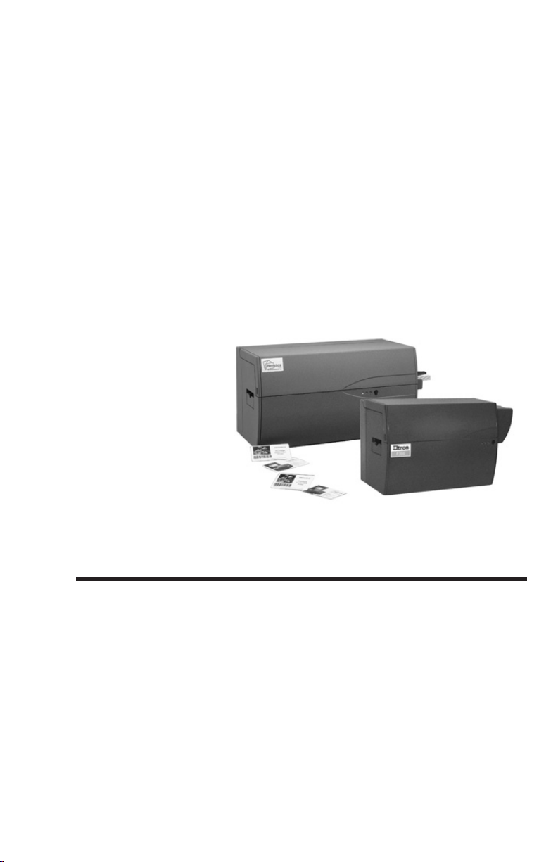
Introduction The Eltron Privilege Series of card printers are
a low cost, high quality printer family specifi
cally designed for printing and encoding of
credit card style plastic cards. The Privilege Se
ries card printers are ideal for personalized
identification, access control, visitor, member
ship, promotion and luggage card, badges and
tags.
-
-
-
980224-001 Rev. C 1
Page 10

Getting Started
Features
300 dots-per-inch print resolution for crisp,
•
clear printing.
Color models use high resolution dye
•
sublimation technology for photo quality
imaging.
Monochrome models use thermal transfer
•
technology.
Over 8 resident bar-code formats and 2
•
printer-resident fonts.
• A 3-Track Magnetic Encoder option that
writes and then read-verifies data. Either
high- or low-coercivity magnetic stripes may
be recorded.
• Magnetic encoder models support printing
and encoding of cardsin a single print cycle.
• Windows™ design and print user software
for both monochrome and color printer
models.
• Windows™ printer control driver that supports True Type fonts is included for color
printer models and monochrome models
with parallel interfaces.
• Compact size in a stylish enclosure.
•
Prints on plain or preprinted plastic materi
-
als of various thickness.
•
A Smart Card Programmer contact station
for programming ISO 7816 contact cards.
•
P400 models allow duplex (dual-sided)
printing in a single print cycle.
2
980224-001 Rev. C
Page 11
Getting Started
P500 and P600 printers are designed to oper
ate in industrial settings. Residential users may
experience TV and/or radio interference. If this
occurs, users must take the corrective steps.
Models All printers have parallel printer ports. Printers
may be ordered in any of the following stan
dard configurations:
Model Description Option
P300CF
P300CML Low Coercivity Magnetic Encoder
P300CMH High Coercivity Magnetic Encoder
Color Dye
Sublimation
P300CE Smart Card Contact Station
P300FML Plus
P300FMH Plus High Coercivity Magnetic Encoder
P300F Plus Parallel Port
Monochrome
Thermal
Transfer
P400CF
Color Dye
P400CML Low Coercivity Magnetic Encoder
P400CMH High Coercivity Magnetic Encoder
Sublimation
with
Duplexer
P400CE Smart Card Contact Station
Note: Printers operated from 120-volt power initially default to High
Coercivity; printers operated from 240-volt power default to Low Co
ercivity. Users can change the default through use or the &C command. See Section 4.
None - Basic Printer Only
Low Coercivity Magnetic Encoder
None - Basic Duplex Printer Only
-
-
-
Options The following options are available:
•
Extended Memory Board- Allows storage of
entire bit map for card.
•
Serial interface suitable for Macintosh™-,
Unix-, and IBM
•
Top-of-Card Magnetic Encoding
980224-001 Rev. C 3
®
-compatible hosts.
Page 12
Getting Started
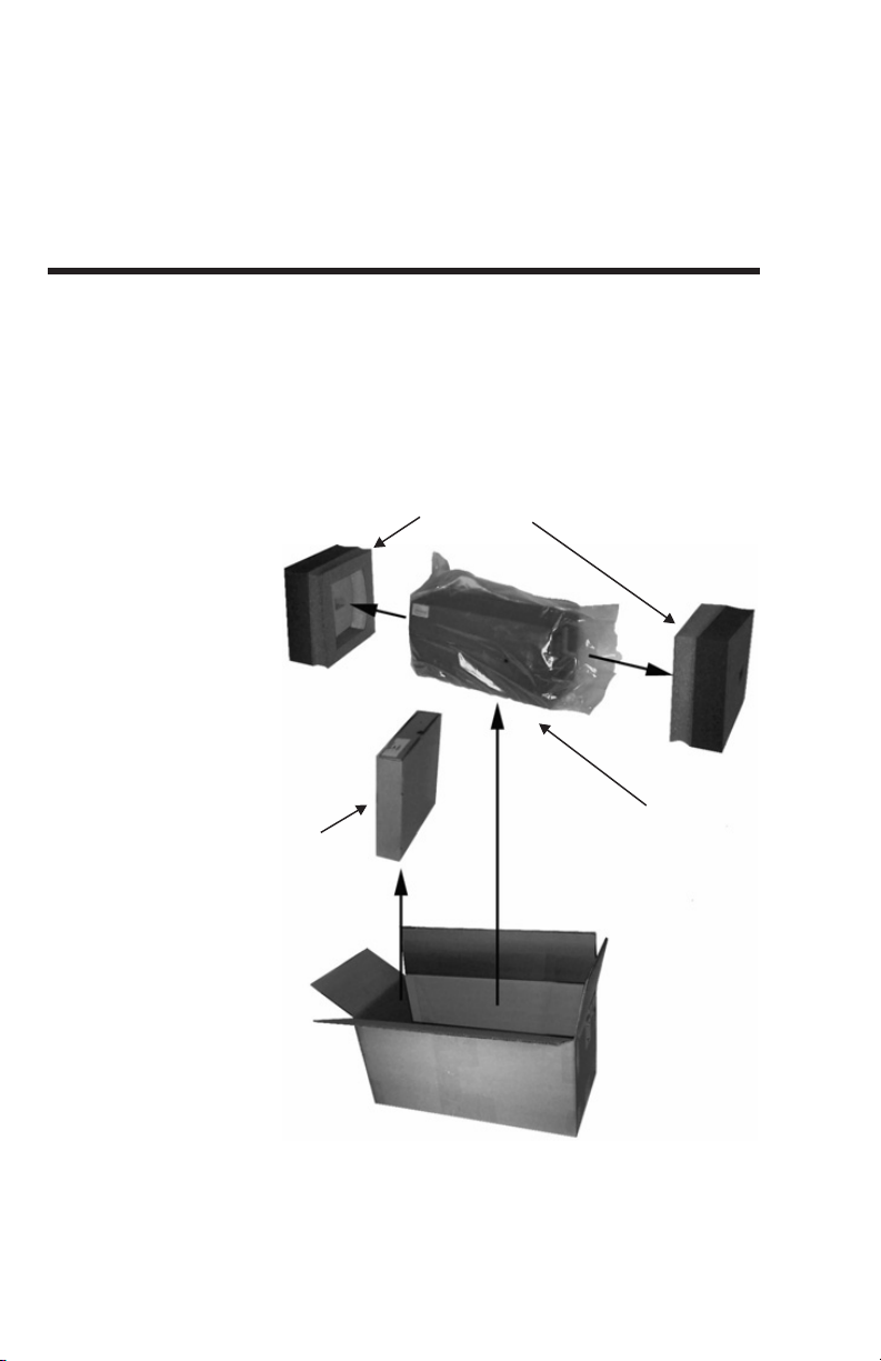
Foam End
Cushons
Printer in
Shipping Bag
Loose Equipment Box:
Printer Cable
Manuals
Card Weight
Software
Accessory Eltron offers a TWAIN-compatible video cap
Unpacking Your
Privilege Card
Printer
Unpacking Your
Privilege Card
Printer
ture system consisting of a video capture card
and video camera. This comprises an ideal
setup for including photos on cards.
Printers ship in cartons and protective bags.
Keep all packing material in case the need to
move or reship the printer becomes necessary.
Avoid touching the electrical connectors topre
vent electrostatic discharge damage while set
ting up the printer.
Foam End
Cushons
-
-
-
Printer in
Shipping Bag
Loose Equipment Box:
Printer Cable
Manuals
Card Weight
Software
4
980224-001 Rev. C
Page 13
Getting Started
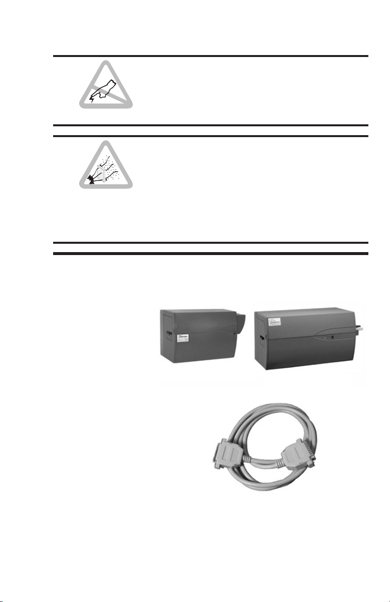
Check List Your Privilege Card Printer kit contains the
Printer (Check for
proper Configura-
tion):
The discharge of electrostatic energy that accu
mulates on the surface of the human body or
other surfaces can damage or destroy the
print head or other electronic components
used in this device.
When unpacking the Privilege card printer
(and card media), be aware that a clean and
nearly dust free environment is required for
proper operation and storage. The print quality
can be effected by dust, body oils and acids
(i.e., finger prints) and exposure to other foreign materials during unpacking or handling of
the printer and media.
items listed below:
-
P300
P400
Interface Cable
980224-001 Rev. C 5
Page 14
Getting Started
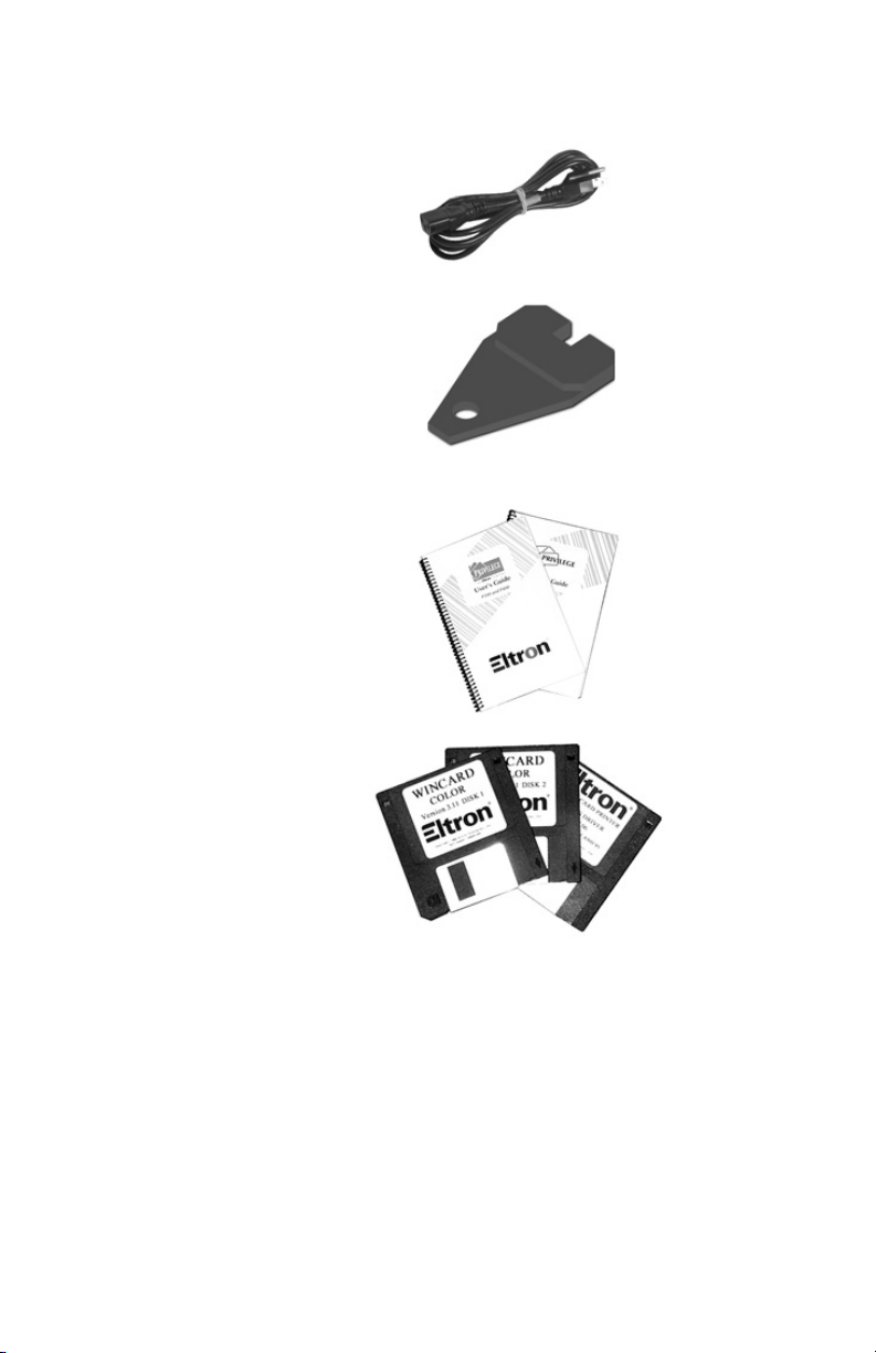
Power Cord
Card Feeder Weight
Manuals:
Printer User’s Guide
WindCard™ Software
•
Windows Drivers
6
Software:
WindCard
If any items are missing, contact your dealer for
replacement parts.
Card media, ribbon, and supplies are available
from your Eltron distributor or call ELTRON at
(800) 344-4003 for the distributor nearest
you. Refer to Appendix B for complete supplies
ordering information.
980224-001 Rev. C
Page 15
Getting Started
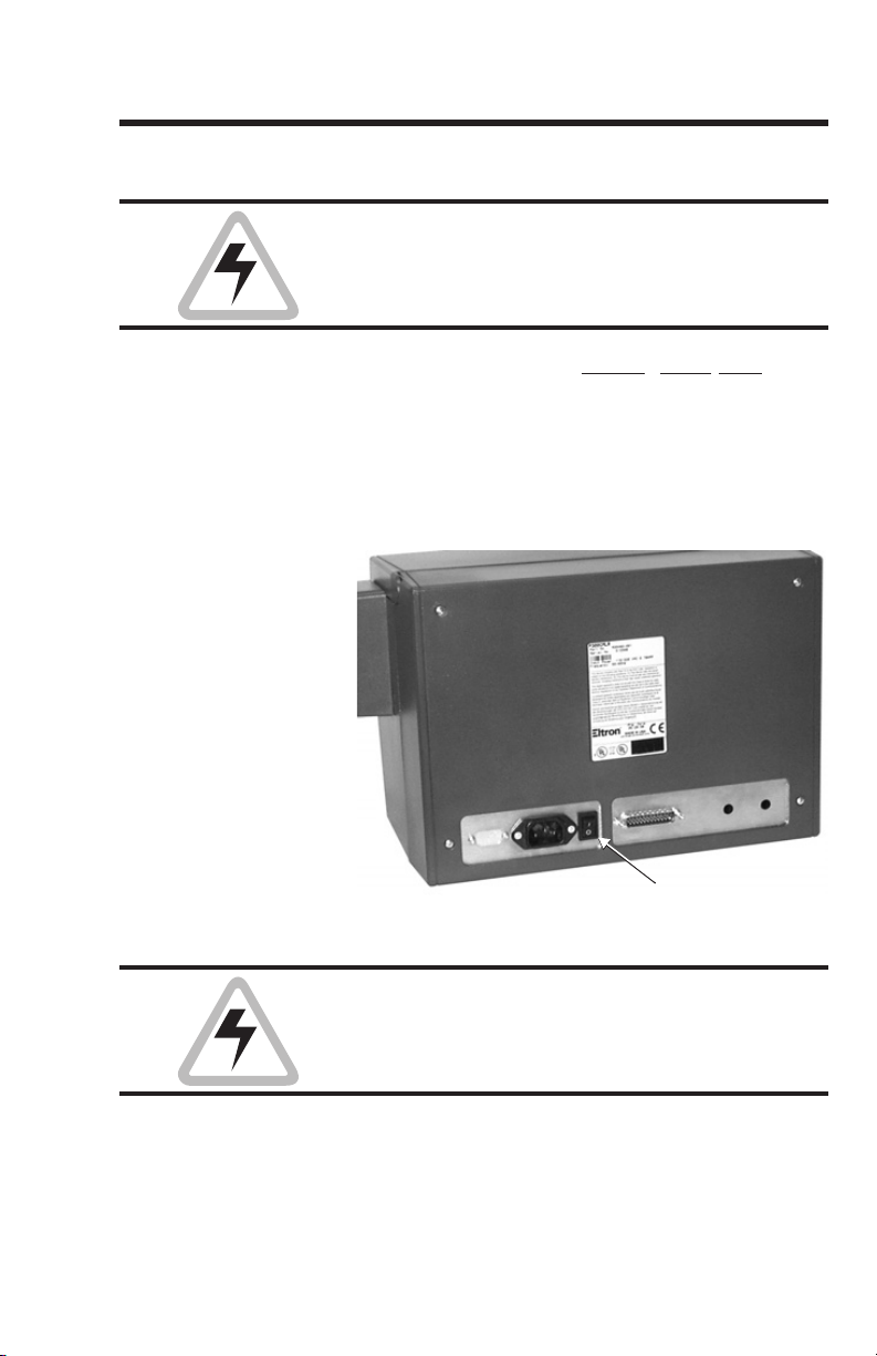
AC Power Switch:
1 = ON
O = OFF
Installation The following sections will guide you through
the installation of the Privilege card printer,
AC power supplied to Privilege card printers
must be current limited to 16-amps or less us
ing an associated circuit breaker or other such
electrical device.
-
Step 1
Attach Power
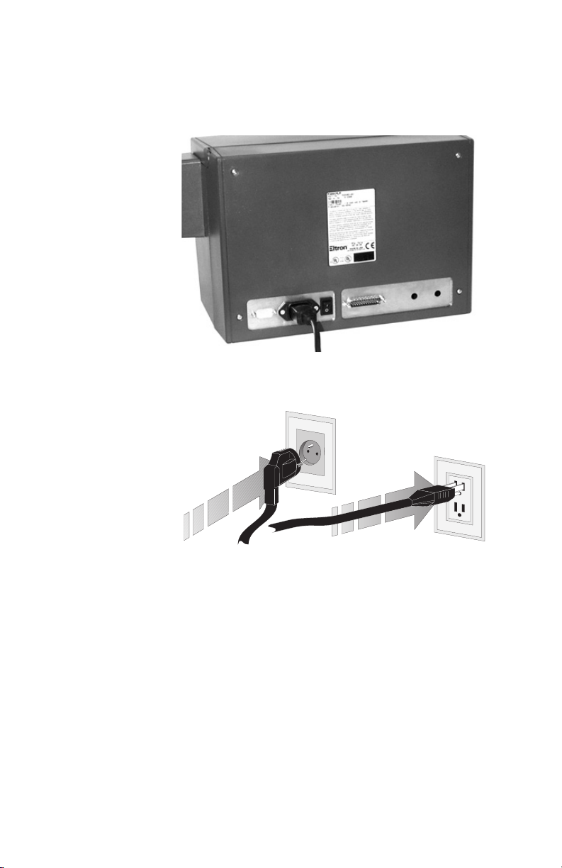
Figure 1-1
Printer
Rear Panel
Place the printer in a clean, dust free loca
tion that allows easy access to all sides of the
printer. The printer should never be operated
while resting on its side or upside down.
Set the AC power switch to OFF (0).
AC Power Switch:
1 = ON
O = OFF
Never operate the printer in a location where
the operator, computer or printer can get wet.
Personal injury could result.
-
980224-001 Rev. C 7
Page 16
Getting Started
Figure 1-3
Power
Connection
Figure 1-2
AC Outlet
Connection
Attach the AC power cord to the AC power re
ceptacle in the rear of the printer.
Attach the AC power cord to a grounded electrical outlet of theproper voltage and plug type.
-
Attach Interface
8
Step 2
Cable
Parallel Interface
Printers with a parallel interface have a male
DB-25 connector. Attach and secure the sup
plied DB-25 (female) to DB-25 (male) parallel
printer cable from the computer’s parallel port
to the parallel interface connector atthe back of
the printer.
Serial Interface
Printers with a serial interface have a female
DB-25 connector. Attach and secure the serial
printer cable from the computer to the DB-25
980224-001 Rev. C
-
Page 17
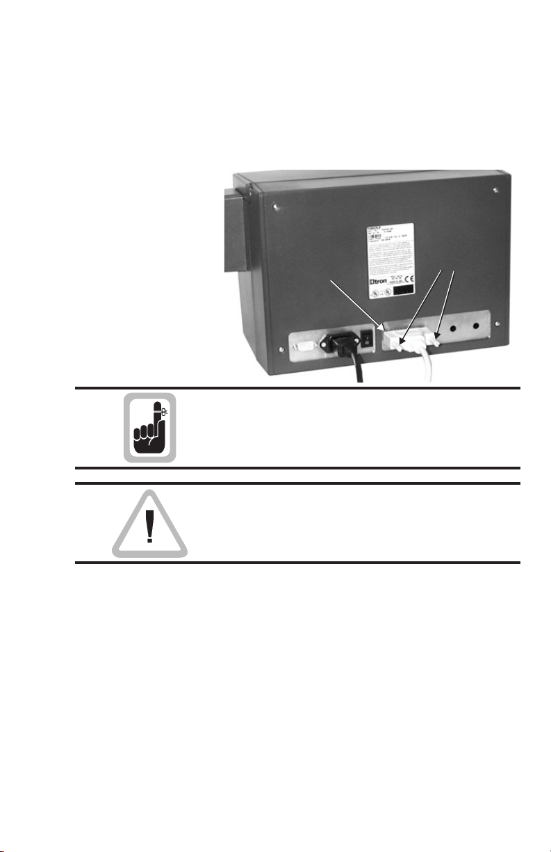
Figure 1-4
Interface
Cable
Secure
Connector
Interface
Cable
Secure
Connector
Interface
Cable
Getting Started
RS-232 serial interface connector at theback of
the printer. The printer’s serial interface is com
patible with DB-9-to-DB-25 serial port adapt
ers.
Secure
Secure
Interface
Interface
Cable
Cable
Connector
Connector
Intermittent or unpredictable operation may
occur from unsecured connectors.
-
-
Only use the printer with the interface cable
supplied. An improper cable can prevent operation, produce radio interference, or cause
damage to the printer.
See Appendixes A and B for cable specifica
tions and ordering information.
980224-001 Rev. C 9
-
Page 18

Getting Started
Step
Applying Power
Removing the
Printer Case
When the power switch is moved to the ON (1)
position, the POWER and ERROR Indicators
should flash. The Power (green) Indicator will
remain on and the ERROR Indicators will turn
off. If the indicators fail to flash or if an ERROR
Indicator remains on, then refer to Appendix A
- Trouble Shooting.
Refer to Section 2 - Operation, for information
on loading cards and ribbons into the Privilege
card printer.
See Appendix C for information on loading the
Windows™ Printer Driver.
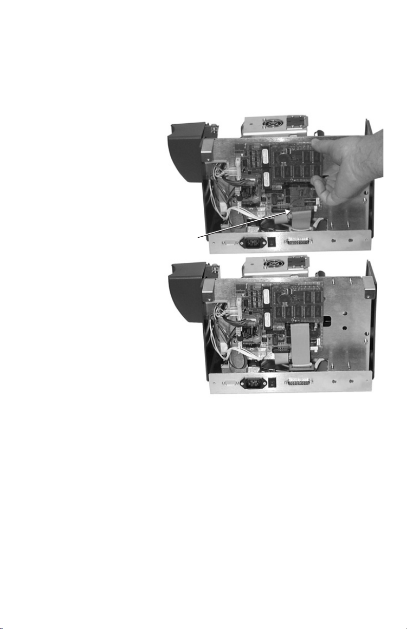
The Extended Memory Board plugs into the
main circuit board of the printer. Access to this
board requires removal of the printer case.
Avoid unnecessary risks! Removal of the
Rear Case of the printer exposes the Main Circuit Board, which contains a lithium battery.
These batteries operatefor long periods of time
and, a replacement may never become necessary. Anyone replacing this battery subjects his
or herself to the following risk:
WARNING:
• A Danger of Explosion exists if the
battery is incorrectly replaced.
• Replace only with the same or
equivalent type recommended by the
manufacturer.
• Dispose of used batteries according
to the manufacturer’s instructions.
10
980224-001 Rev. C
Page 19
Getting Started
Remove
Screws
Case removal exposes circuit points that, if
touched with power on, can present a hazard.
Therefore, never remove any case
component without first unplugging the
Power Cord.
Case Removal
Step
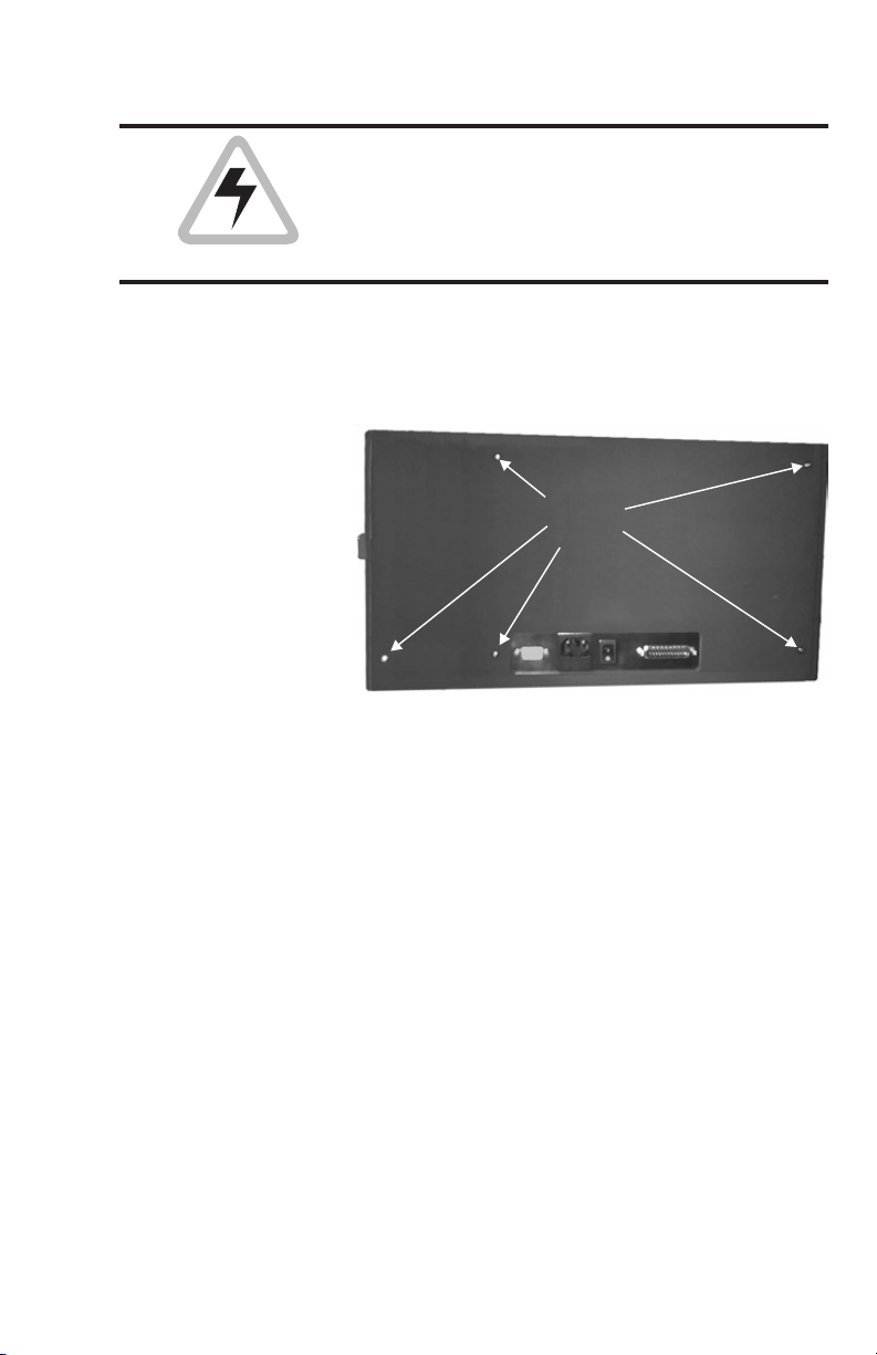
Figure 1-5
Screws Holding
Case
Case Removal
Step
Using a medium sized Phillips screwdriver, re
move the screws that secure the case. P400
printers have five (5) screws, and the other
models have four (4).
Remove
Screws
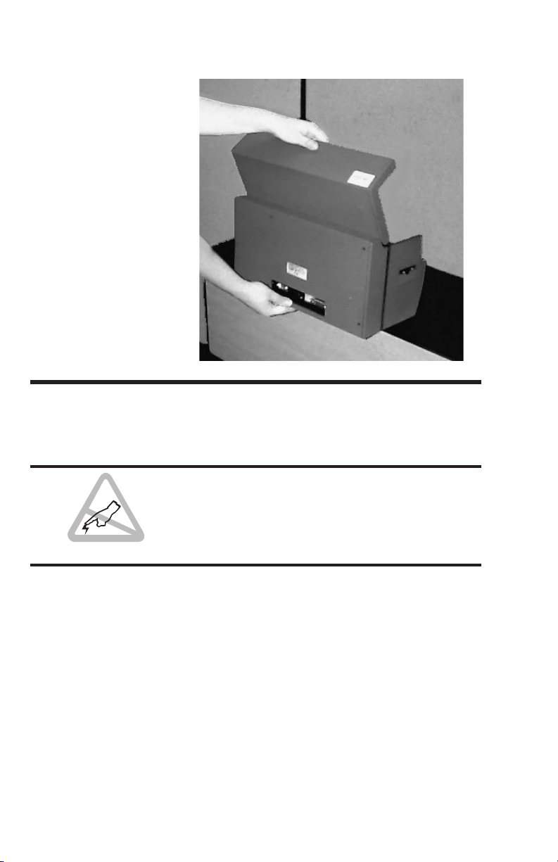
Rest the printer on a table such that the rear
edge hangs over by about two and one-half
(2-1/2) inches.
Open the lid, and while holding the lid in one
hand and the bottom edge with the other,carefully slide the case off.
-
980224-001 Rev. C 11
Page 20
Getting Started
Case Removal
Figure 1-6
Memory Board
Installation
The addition of a Memory board allows the
host computer to download a complete image
all at once, instead of the panel-by-panel
downloads that occur without this addition.
Before touching any of the circuit components
on either the printer or the Expanded Memory
board, be sure todischarge any static charge by
touching an electrical ground point. If possible
wear a grounding wrist band.
12
980224-001 Rev. C
Page 21
Getting Started
Unplug
Cable First
Installing the
Memory Board
Step
Figure 1-7
Extended Memory
Installation
Unplug the connector centered below the
Memory board. Plugin the Memory Board into
the two connectors on the upper right side of
the main circuit board
Unplug
Cable First
Installing the
Memory Board
Replace the cable and printer case by reversing
the steps performed during their removal.
Step
980224-001 Rev. C 13
Page 22

Getting Started
14 980224-001 Rev. C
Page 23

2
Operation
This section contains information on the operation of the Privilege card printer.
Controls &
Indicators
The POWER
SWITCH
The POWER
Indicator
980224-001 Rev. C 15
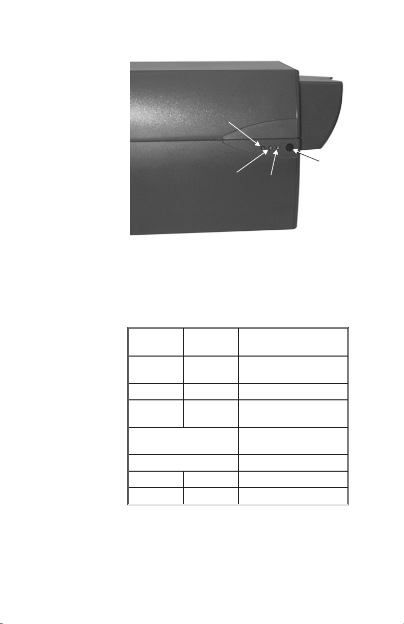
All the Privilege card printer controls and indicators, except for the power switch, are located
on the front of the printer. There are three (3)
indicator lights and one control button on the
front panel.
The POWER SWITCH is located on back
panel of the printer. Placing the switch in the
ON (1) position applies power to the printer.
Placing the switch in the OFF (0) position turns
off the printer. See Figures 1-1 and 1-2 in Sec
tion 1.
The POWER SWITCH also works in con
junction with the Panel Button. See the
Panel Button on the following pages.
The POWER indicator light is green when
power is ON. See Figure 2-1.
-
-
Page 24
Operation
Panel
Button
Power
Indicator
Printer Control
and Indicators
Figure 2-1
Power
Indicator
Status B
Status C
Panel
Button
The STATUS
Indicators
The STATUS indicator lights are amber. The
STATUS indicators report data or command
activity, command errors, or hardware faults,
as follows:
Status B
Indicator
ON OFF
Status C
Indicator
Activity or Error
Description
Data in transfer or executing command
Flash OFF Command Code Error
Flash ON
Flashing Together
Encoder Command
Code Error
Print Head too Hot
(Automatic Wait)
Alternate Flashing Cover Open (P400)
OFF ON End of ribbon
ON ON Mechanical Error
See Appendix A for troubleshooting tips.
16
980224-001 Rev. C
Page 25
Operation
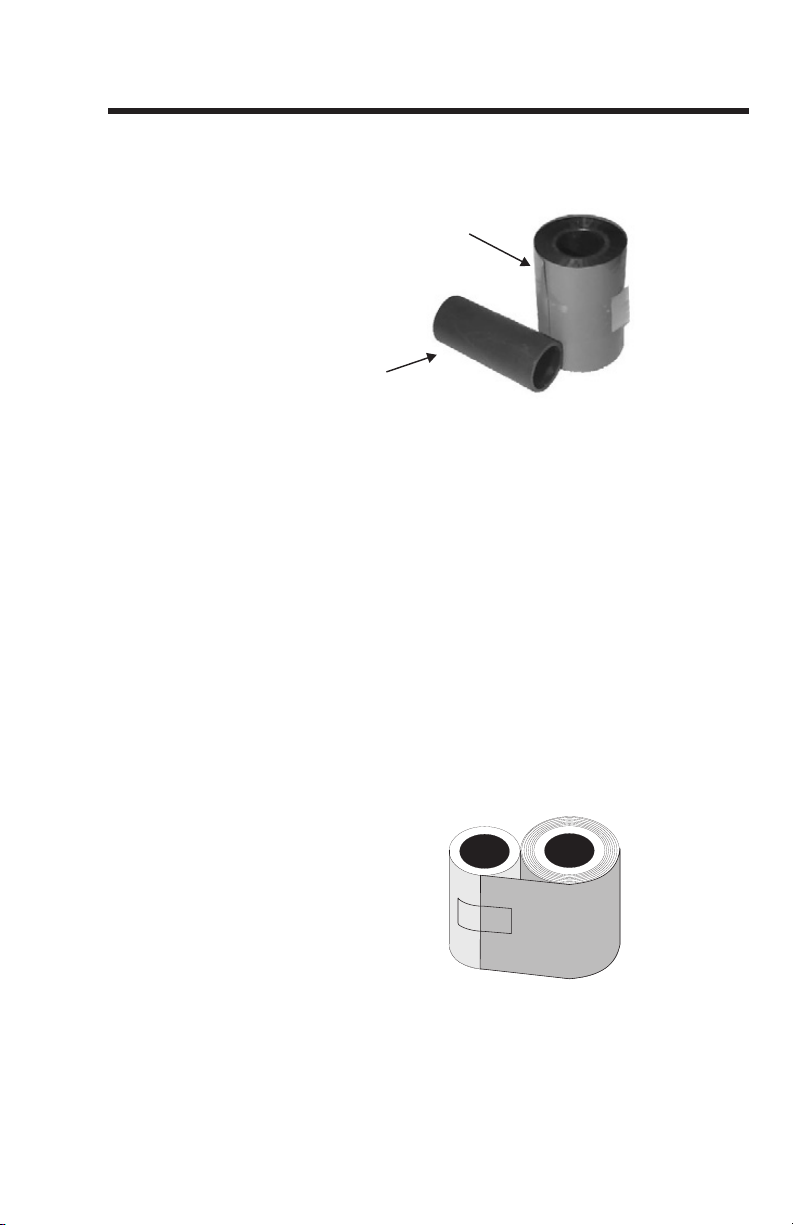
Empty
Core
Ribbon
Preparation
Figure 2-2
Ribbon and
Empty Core
Ribbon
Preparation
Step 1
Ribbon
Preparation
Step 2
Ribbon
Preparation
Step 3
To prepare the ribbon, the taped end must be
fastened to an empty core. Eltron recommends
the following:
Ribbon
Empty
Core
Place both the ribbon and an empty core on
end, next to one another, and touching.
Remove the tape end that fastens the ribbon
end to the roll such that the end with tape attached can be unwound.
Unwind enough ribbon to reach the empty
core and tape the end down. If both the ribbon
roll and the empty core are kept touching during this step, ribbon will be centered on the
core and ribbon take-up will occur without
wrinkling.
Figure 2-3
Ribbon
Preparation
Ribbon
Preparation
Wind one or two turns of ribbon onto the rib
bon core.
Step 4
980224-001 Rev. C 17
-
Page 26
Operation
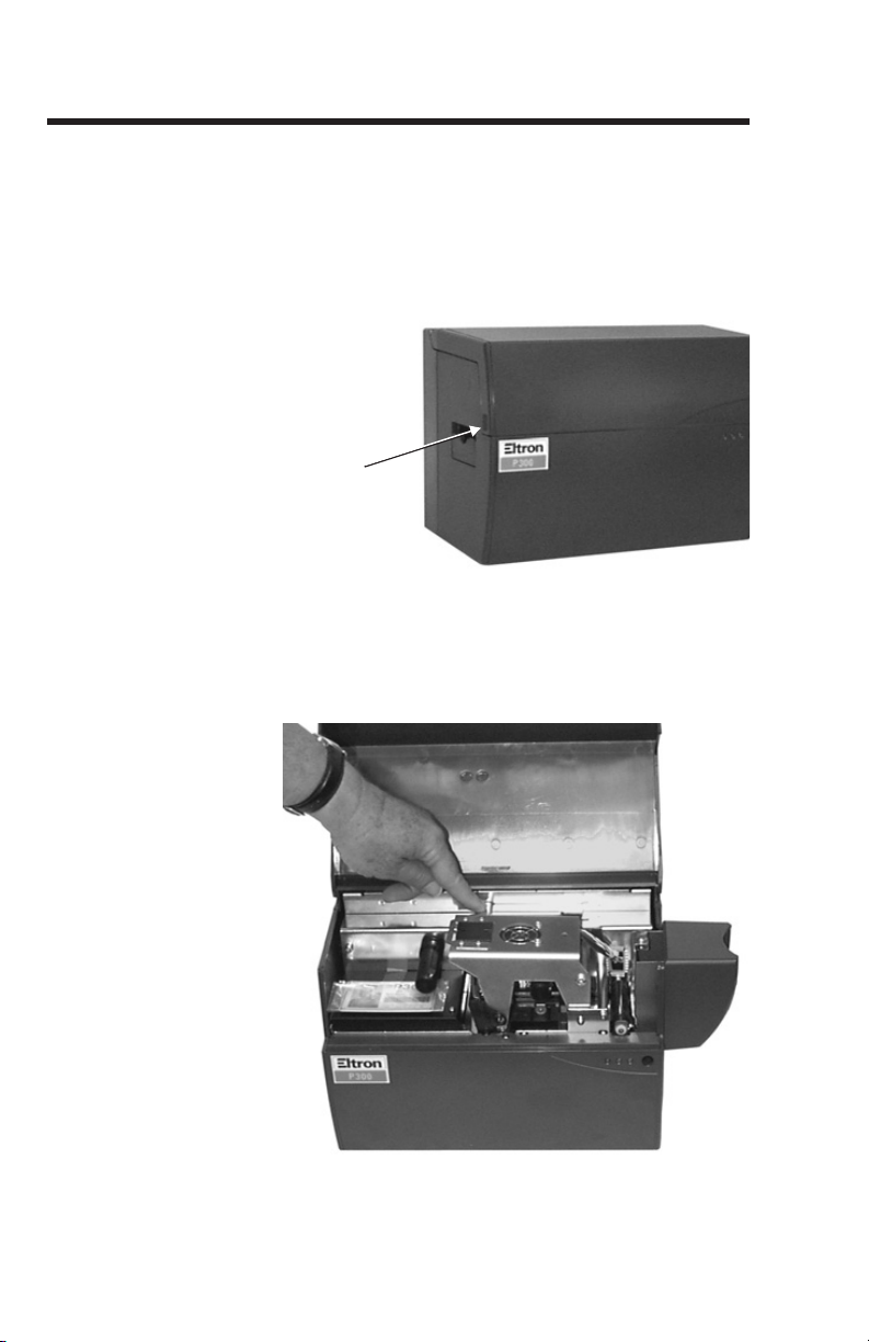
Lift at
Recess
Ribbon Loading Ribbon loading involves the placement of the
prepared ribbon onto the Supply and Take-up
spindles, as follows:
Ribbon Loading
Step 1
Figure 2-4
Raising the Cover
Ribbon Loading
Step 2
Figure 2-5
Raising the
Print Head
Lift the printer’s access cover open. Hold by
the recessed areas on the sides of the cover.
Lift at
Recess
Press down on the Print Head Release Latch to
open the Print Head Carriage. The Print Head
Carriage will pop open.
18
980224-001 Rev. C
Page 27
Operation
Ta k e U p
Spindle
Supply
Spindle
Supply
Spindle
Ta k e U p
Spindle
Ribbon Path
(CAUTION: Print Head damage can occur if not as shown.)
Ribbon Path
(CAUTION: Print Head damage can occur if not as shown.)
Ribbon Loading
Step 3
Figure 2-6
Ribbon Path
DO NOT TOUCH the Print Head or the elec
tronic components on thePrint Head Carriage.
The discharge of electrostatic energy that accu
mulates on the surface of the human body or
other surfaces can damage or destroy the print
head or electronic components used in this de
vice.
Unroll enough ribbon to span the distance be
tween the Supply and Take Up spindles. Then,
at the same time, slide the Supply and Take Up
Cores onto their respective spindles. Make sure
to push both fully onto the spindles. Also make
sure that the ribbon comes off of the top of the
Supply Spindle and feeds onto the top of the
Take Up Spindle.
Supply
Ta k e U p
Ta k e U p
Spindle
Spindle
Supply
Spindle
Spindle
-
-
-
-
Ribbon Path
Ribbon Path
(CAUTION: Print Head damage can occur if not as shown.)
(CAUTION: Print Head damage can occur if not as shown.)
Take extra care when installing the printer
ribbon. The Print Head may be damaged or
will require an extensive cleaning if the wrong
side of the ribbon is used when printing.
980224-001 Rev. C 19
Page 28
Operation
Press Here to
Latch Down
Print Head
Ribbon Loading
Step 4
Figure 2-7
Latching Down
Print Head
Push the Print Head Carriage down and press
the Print Head Latch Lock down. The latch will
make an audible click when it locks.
Press Here to
Latch Down
Print Head
20
980224-001 Rev. C
Page 29

Operation
Ribbon Loading
Step 5
Handling
the Media
Initialize ribbon after changing or replacing rib
bons and following a mechanical error. To ini
tialize the ribbon for card printing:
Color Printer, Color Ribbon - Press and
hold the Panel Button until the ribbon ad
vances. The ribbon should stop with the print
head between a clear and a yellow panel.
Color Printer, Black Plus Overlay Rib
bon - Press and hold the Panel Button until the
ribbon advances. The ribbon should stop with
an overlay panel centered at the print head.
Color Printer, Monochrome Ribbon -No
initialization required.
Monochrome Printer - Use Monochrome
ribbons only. No initialization required.
The printer and media (cards) require a clean
and nearly dust free environment for proper
operation and storage. The print quality can be
effected by dust, body oils and acids (e.g., finger prints) and other foreign materials encountered during unpacking or handling of the
printer and media.
-
-
-
-
New cards in the media packaging usually
have a high electrostatic charge. This charge
can cause the cards to stick together making
card loading difficult. Some of this adhesive
force can be reduced by shuffling the stack of
cards. Do not over bend the card media or
touch the print surfaces of card.
980224-001 Rev. C 21
Page 30

Operation
Card-Feed
Extender
Card-Feed
Extender
DO NOT set unprinted cards on dust or lint
carrying surfaces, i.e., table tops, cloth, com
puters, etc..
DO NOT place media with the magnetic stripe
near or on magnetic sources, such as: moni
tors, non-electronic phones, paper clip hold
ers, speakers, etc.
-
-
-
Card Gate
Adjustment
Figure 2-8
Extending
Feeder Slide
Two Card Gate Adjustment procedures exist: a
Static procedure and a Dynamic procedure.
Both procedures setup the printer to allow just
one card to feed at a time. If two cards feed, a
card jam results. Repeat one of these procedures whenever switching to a different card
thickness. For both procedures, begin by pulling out the Card-Feed Tray Extender. This produces the proper angle for card feeds.
Card-Feed
Card-Feed
Extender
Extender
22
Prevent Media Jams!
Adjusting the Card Feeder is critical for proper
mechanical operation of the printer.
980224-001 Rev. C
Page 31

Operation
Card-Gate
Adjust Knob
Gate
Opening
Static Card Gate
Adjustment /
Media Loading
Step 1
Figure 2-9
Card Gate
Adjustment
Gate
Opening
Place a single card into the Card Feeder. Adjust
the Card Gate to allow the single card through
the gate. Turn the screw counterclockwise to
lower the gate andclockwise to raise the gate.
Slide the card out of the Card Gate and place
the Card Weight on top of the card. Verify that
the card still passes through the gate.
Card-Gate
Adjust Knob
Weight
Card
980224-001 Rev. C 23
Page 32

Operation
Static Card Gate
Adjustment /
Media Loading
Step 2
Figure 2-10
Card Gate
Adjustment
Place two or more cards (with the Card
Weight) into the Feeder.Push the bottom cards
in the stack into the feeder gate. Verify that the
second card in the stack cannot slide through
the gate.
24
Weight
980224-001 Rev. C
Page 33

Operation
Dynamic Card
Gate Adjustment /
Media Loading
Step 1
Figure 2-11
Checking the
Card-Gate
Opening
Correct
To adjust the card gate dynamically, begin by
completely closing the card gate, and placing
several cards of the desired thickness in the in
put tray, topped with the card weight. Turn the
screw counterclockwise to lower the gate and
clockwise to raise the gate.
-
Incorrect
980224-001 Rev. C 25
Page 34

Operation
Dynamic Card
Gate Adjustment /
Media Loading
Step 2
Issue a Card Feed Command (with no print
ing), and gradually raise the Card Gate until
just one card feeds. Each Card Feed command
produces about a five (5) second attempt.
When a card fails to feed within this time-out
period, another Card Feed command be
comes necessary. Make sure to double check
the setting, making sure only one card feeds at
a time. Otherwise media jams can occur.
Card Feed commands can be issued as fol
lows:
From the Windows Driver (See Appendix C),
type:
ME <CR>
From WindCard (See WindCard manual), Select Printer Tools. In the Printer Tools dialog
box Enter:
ME <CR>
After reaching the point where one card feeds,
add a quarter turn clockwise to assure that the
cards feed freely.
-
-
-
26
Printer
Access and
Usage
The Privilege card printer requires at least three
(3) inches of free space around all sides for ac
cess to printer controls, card input and card
output.
980224-001 Rev. C
-
Page 35

Operation
Tray Pulled Out
and Tipped Down
Do Not Operate Printer with Cover
Open.
Do Not Close Output Tray With Cards
Present.
To maintain a clean printing environment and
to prevent ESD damage, keep the cover of the
printer closed except during maintenance and
ribbon loading procedures. Some models have
an interlock that prevents print cycles with the
cover open.
With a fixed amount of space available, the
maximum number of cards the Output Tray
can hold varies as a function of card thickness.
The Output Tray can hold up to 20 of the 30mil (0.762 mm) cards, 45 of the 20-mil (0.508
mm) cards, and 90 of the 10-mil (0.254 mm)
cards. After the tray fills, cards begin spilling
onto the surface below the tray. Spilling onto
this surface also occurs with the printer operated with the Output Tray pushed in. For high
volume printing, operation with the tray
pushed in may be preferred.
Figure 2-12
Card Output
Tray
Tray Pulled Out
and Tipped Down
980224-001 Rev. C 27
Page 36

Operation
Printing When the ribbon and card media are loaded as
per the procedures previously described, and
the printer power is on, the Privilege card
printer is ready to print.
Printing requires the WindCard™software, (a
Windows™ software program),the Windows™
printer driver or direct printer command level
programming through the printer interface.
Printing a Test
Card
Figure 2-13
Color Printer
Test Card
Figure 2-14
Monochrome
Printer Test Card
The printer will print a Test Card if the
Panel Button is pressed and held in while
printer power is turned on. The Panel Button
can be released after the STATUS C indicator
turns off. Remember to synchronize the ribbon
for any color printing.
28
980224-001 Rev. C
Page 37

Operation
Adjustments The Privilege card printers have no user adjust
able features except for the card gate adjust
ment, see preceding pages.
Protect Your Factory Warranty!
Neglect in performing recommended cleaning
procedures can void your warranty, as can im
proper packaging and shipping.
Other than the recommended cleaning proce
dures described in this manual, only allow
Eltron factory authorized technicians to service
Privilege printers.
NEVER loosen, tighten, adjust, bend, etc. any
part or cable inside the printer.
The only user adjustable features of the Privilege card printers are made in software (or programming) and the card feeder gate
adjustment.
Physical Printing
Process
A sensor signals when the feeder roller feeds a
card into the drive system. Cleaning Rollers remove dust or lint, and drive rollers accurately
move the card under the print head. The print
head carriage physically moves down to the
surface of the card for printing. Printing occurs
with ribbon movement and card movement
synchronized. The card ejects at the end of a
print cycle.
-
-
-
-
Monochrome
Printing
The print operation is as described above. The
thermal transfer ribbon is advanced as the card
is advanced.
980224-001 Rev. C 29
Page 38

Operation
Color Dye
Sublimation
The color print process involves multiple
passes of the card under the print head. Each
pass of the card prints/bonds a different color
or material onto the card. The position of the
card is accurately controlled with the drive and
platen rollers under the card. For printers with
out Extended Memory, the typical print se
quence for CYMK with Overlay Ribbon
proceeds as follows:
Printer ribbon synchronizesto the yellow (Y)
•
ribbon panel prior to printing. If not, press
the RESET button to re-synchronize.
• Card from Input Tray feeds into printer.
• Data for Yellow (Y) panel downloads.
• Yellow Printing occurs.
• Card moves back, and ribbon advances to
next panel.
• Download, print, return card, and synchronize steps occur for ribbon panels Magenta
(M), Cyan (C), Black (Dye or Resin) and
Overlay. For duplex (two-sided) card printing (P400 Models), cards move back to the
card-flip before returning again to the print
head. Cards printed on both sides always
eject with the sideinitially printed facing up.
-
-
30
•
Card ejects.
980224-001 Rev. C
Page 39

Operation
Cleaning The
Printer
Quality card images require a clean, dust- and
lint-free printer. Any particles left on the
mechanisms in the card path can migrate onto
cards and interfere with both YMC dye
sublimination and resin thermal transfer.
These ribbon materials cannot penetrate any
particles left on the cards. The need for clean
ing varies, depending upon print environment
and usage.
Never use a shop air compressor to blow
away particles in the printer. Air compres-
sors can contain rust-inhibiting oil and may
have ineffective moisture traps. Oil and moisture adversely affect print quality, and when
sprayed, may spread contaminates throughout
the printer.
Also canned air requires a very careful usage.
Avoid directing an air stream in a way that
distributes particles from areas having a significant particle contamination.
Any vacuum used must have its outflow well filtered and directed away from the printer.
Never attempt to vacuum particles off of the
Print Head, as damage to delicate imaging elements can result.
-
980224-001 Rev. C 31
Page 40

Operation
Bend to Break
and Release Fluid
Eltron offers the following items for cleaning
the printer:
Disposable, Clean Non-fibrous (foam)
•
swabs with alcohol filled handle for head
cleaning and suitable for roller cleaning
An alcohol filled, felt pen suitable for roller
•
cleaning
Bend to Break
and Release Fluid
• A Cleaning Kit comprised of a spray can of
alcohol and a package of cleaningcards suitable for a general cleaning but required for
Magnetic Encoder head cleaning.
32
Cleaning products for the Privilege card printer
are available directly from your Eltron distribu
tor or call Eltron at (800) 344-4003 for the
distributor nearest you.
980224-001 Rev. C
-
Page 41

Operation
Alternate cleaning materials can include the
following:
Foam swabs (never use cotton or any other
•
fibrous material.)
99% pure or better Isopropyl Alcohol for
•
moistening swabs
Clean Running Water (Used for Upper
•
Cleaning Roller only).
Card Path
Elements
Figure 2-15
Media Path
Figure 2-15 shows the elements in the card
path that require a periodic cleaning. Procedures follow for the following items:
• Card Guides, Smart Card contacts, and Encoder Read-Write heads.
• Card Feed Roller
• Cleaning Rollers
• Print Head
• Transport and Platen Rollers
Card
Path
Card Feed
Card-Flip
Assembly
Roller
Cleaning
Rollers
Shroud
Ribbon
Take Up
Transport
Rollers
Print Head
Up/Down Cam
P300
Print Head
Magnetic
Encoder
(Option)
980224-001 Rev. C 33
Platen
Roller
Smart
Card
Station
(Option)
P400
Cleaning
Rollers
Card
Feed
Roller
Card-
Flip
Pulley
Page 42

Operation
When To Clean Cleaning frequency varies with different envi
ronments. Typically, a cleaning that follows
ribbon depletion will keep the card printer op
erating properly. If not, consider either another
printer location or a more frequent cleaning.
Cleaning
Stationary Card
Path Items
Using the
Cleaning Kit
Step 1
Using the
Cleaning Kit
Items in the card path that cannot be reached
directly require a cleaning using the alcoholmoistened cards of the Cleaning Kit. Encoder
Read-Write heads require thiskind of cleaning.
Remove the ribbon from both the Supply and
Take Up spindles. See Ribbon Loading in this
section.
Moisten a Cleaning Card by spraying with alcohol. Do Not soak.
Step 2
Using the
Cleaning Kit
Step 3
Place the moistened Cleaning Card in the Input Tray, topped with the card weight. If necessary, adjust the Card Gate for the card
thickness. (Since this procedure calls for only
one card, you can open the gate as much as
you like.)
-
-
34
Using the
Cleaning Kit
Step 4
Send the Cleaning Card through the printer
several times without enabling printing. De
pending on the setup,use one of the following:
Where:
= Space
↵ = Enter
Entry is either via WindCard™ (see manual) or
The Windows Driver (see Appendix C).
980224-001 Rev. C
-
Page 43

For P300:
M5!S[MM2200[MB
For P400:
M5!S[MM2200[!Z[MM20001
Also for single-pass card feed
ME↵
Operation
Cleaning the
Card-Feed Roller
Cleaning the
Feeder Roller
Step 1
Cleaning the
Feeder Roller
Step 2
Figure 2-16
Card-Feed Roller
Only the Card-Feed Roller resides outside the
printer case. A stack of clean cards and/or the
Card Weight should say in the Input Tray as a
defense from airborne particles. If left uncovered for any extended period, a preprint cleaning should occur.
Remove any cards from the printer’s feeder.
Clean the roller using a Swab or Cleaning Pen.
To gain access to initially unexposed areas, cycle the roller by applying the printer power
while holding the Panel Button on for three (3)
seconds (see Test Card sequence in Controls
and Indicators, Section 2.) Let the roller air dry
for two (2) or more minutes.
980224-001 Rev. C 35
Page 44

Operation
Upper
Cleaning
Roller
Spring
Clip
Cleaning the
Upper and Lower
Cleaning Rollers
Cleaning the
Cleaning Rollers
Step 1
Figure 2-17
Upper Cleaning
Roller
Upper
Cleaning
Roller
Spring
Clip
These rollers pick up cards fed from the Input
Tray. The upper roller has a coating that col
lects any loose particleson the surface of cards.
Remove any cards from the printer. Open the
printer cover. Remove the Upper Cleaning
Roller. Gently pull the Spring Tab out to free
the Upper Cleaning Roller pin. Then, remove
the Upper Cleaning Roller.
-
Cleaning the
Cleaning Rollers
Step 2
Cleaning the
Cleaning Rollers
Step 3
36
Clean the Upper Cleaning roller with running
water. Then allow the roller to air dry without
resting the rubberized part on a surface.
Use a swab or cleaning pen on the Lower
Cleaning Roller. Cycle the rollers by applying
the printer power while holding the Panel But
ton on for three (3) seconds to expose initially
unexposed areas. This is the Test Card se
quence described in Controls and Indicators,
Section 2.
980224-001 Rev. C
-
-
Page 45

Figure 2-18
Lower Cleaning
Roller
Operation
Cleaning the
Cleaning Rollers
Step 4
Print Head
Cleaning
Reinstall the Upper Cleaning Roller. First slide
the shaft pin into the hole in the chassis opposite the Spring Tab.
DO NOT
touch the roller surface that contacts
the media.
Snap the opposite shaft pin of theroller intothe
hole on the Spring Tab.
Without touching the body of the roller, make
sure the roller locks in place. To avoid contamination, always hold the roller by the metal
ends.
During printing, the ribbon isolates the Print
Head from the cards. Therefore, the ribbon has
the greatest influence on Print Head contami
nation. An improperly installed ribbon, with
the dye and resin deposits facing the Print
Head can cause permanent damage. No
amount of cleaning can remove dye or resin
fused onto the delicate Print Head elements.
-
980224-001 Rev. C 37
Page 46

Operation
Print Head
Cleaning
Step 1
Print Head
Cleaning
Step 2
Figure 2-19
Cleaning
Print Head
Turn the printer power OFF. Open the cover.
Open the print head Carriage and Remove the
Ribbon and Ribbon Core. See Ribbon Load
ing, in this Section.
The print head should only be cleaned with a
solution of 99% pure Isopropyl Alcohol and a
clean non-fibrous (foam) swab.
Avoid touching the Print Head elements. The
release of Static charges can damage the Print
Head elements and Internal circuits.
Gently rub the alcohol-moistened swab across
the print head from the front to the back of the
printer. Do Not Soak the Print Head.
-
38
Allow the printhead to dry for 2 minutes before
reloading the ribbon and core.
Initiate a Test Card sequence. See Printing a
Test Card is this section.
980224-001 Rev. C
Page 47

Operation
Shroud
Fasteners
Cleaning the
Transport and
Platen Rollers
Cleaning Platen
and Transport
Rollers
Step 1
Cleaning Platen
and Transport
Rollers
Step 2
Figure 2-20
Encoder Shroud
Shroud
Fasteners
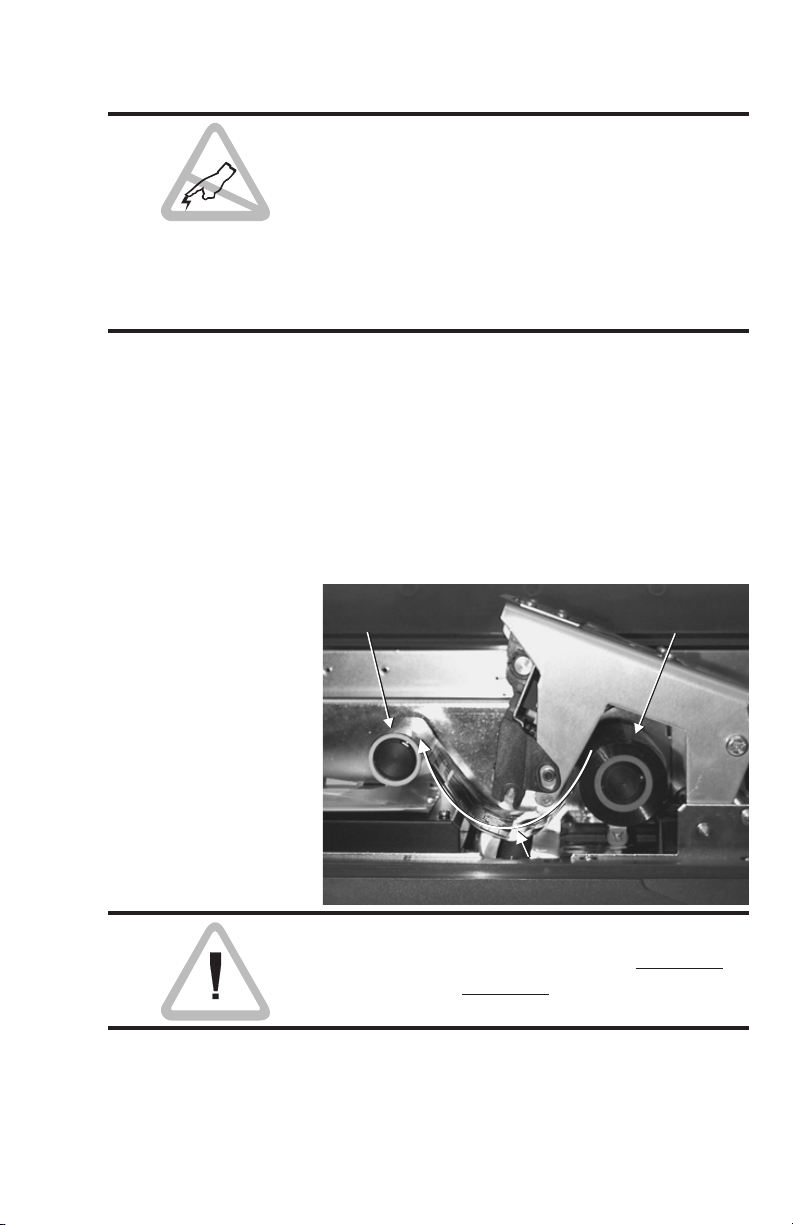
Along with the Cleaning Rollers, these rollers
move the cards between the Input and Out
put Trays. Except for the Platen, these rollers
operate in pairs—a lower drive roller and an
upper pinch roller to hold the cards against
the drive roller.
Open the Cover, unlatch and raise the Print
Head, and remove any ribbon. Note that all
are described in previous parts of this section.
Remove the Shroud that covers the area that
has the Magnetic Stripe Encoder in printers so
equipped. Note that two self-tapping screws
hold the Shroud in place.
-
In the following steps, cycle the rollers to
reach initially unexposed areas by applying
the printer power while holding the Panel
Button pressed for three (3) seconds. This is
the Test Card sequence described in Controls
and Indicators in this section.
980224-001 Rev. C 39
Page 48

Operation
Encoder
Rollers
Encoder
Rollers
In the following steps, avoid touching the Print
Head. A static discharge can damage delicate
Print Head elements aswell as internal circuits.
Cleaning Platen
and Transport
Rollers
Step
Figure 2-21
Encoder Transport
Rollers
Cleaning Platen
and Transport
Rollers
Step
Using an alcohol-moistened Swab or a Felt
Pen, clean the two sets of rollers exposed with
removal of the Shroud
Encoder
Encoder
Rollers
Rollers
Using an alcohol-moistened Swab, clean the
Platen Roller.
40
980224-001 Rev. C
Page 49

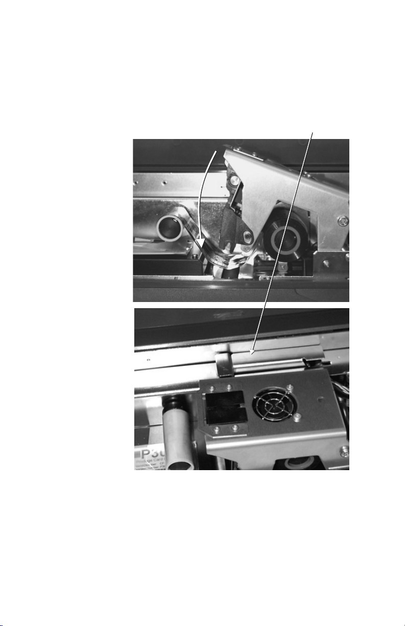
Figure 2-22
Print
Station
Rollers
Platen Roller
Operation
Cleaning Platen
and Transport
Rollers
Step
Figure 2-23
Print Station Rollers
Print
Station
Rollers
Using an alcohol-moistened Swab, clean the
roller pair under the Print Head Cage
980224-001 Rev. C 41
Page 50

Operation
Card-Flip
Rollers
Cleaning Platen
and Transport
Rollers
Step
Figure 2-24
Card-Flip Rollers
Card-Flip
Rollers
Cleaning Platen
and Transport
Rollers
Step
Using an Alcohol-moistened Swab, clean the
Card-Flip Rollers (P400s only).
Replace Encoder Shroud (see Step 2), install,
Ribbon, place cards in the Input Tray, and print
some Test Cards. Inspect the cards for Print
Anomalies. If Anomalies appear, refer to Appendix A, Troubleshooting.
42
980224-001 Rev. C
Page 51

3
Magnetic Card Stripe Encoder
This section includes information on the additional operation and maintenance requirements of a Privilege Series card printer
equipped with the Magnetic Card Stripe Encoder option. Users can set these models to
record on either low- or high-coercivity magnetic card stripes. Printers that operate from
120-volt power default to a high coercivity setting; printers that operate from 240-volt power
default to low coercivity.
Introduction Privilege card printer models designated as ei-
ther ML or MH (e.g., P300FML and
P400CMH) have a magnetic stripe encoder
built into the printer. The general operation of
a printer with the encoder optionis nearly iden
tical to standard model printers.
-
Only use cards with flush magnetic stripes.
Never use pasted-on stripes.
980224-001 Rev. C 43
Page 52

Magnetic Card Stripe Encoder
Up-Facing Stripe
(Models with R Suffix)
Down-Facing Stripe
(Models without R Suffix)
Media Loading
Orientation
Figure 3-1
Magnetic Stripe
Position
Most Privilege printers with Magnetic Encoders
have their read/write heads positioned below
the path traveled by the cards. For these print
ers, load the media (cards) with the magnetic
stripe facing down and closest to the rear of the
printer. However, Eltron also supplies printers
with read/write head positioned above the
path traveled by the cards. For these printers,
load the cards with the magnetic stripe facing
up and closest to the rear of the printer.
Up-Facing Stripe
(Models with R Suffix)
Down-Facing Stripe
(Models without R Suffix)
-
Ensuring Data
Reliability
Conventions
44
Command
A read verify pass is always performed on all
encoded cards to guarantee data integrity.
Either Software (WindCard™) or command
programming controls the Write and Readverify data processes.
= Escape
= Space
↵ = Return
980224-001 Rev. C
Page 53

Magnetic Card Stripe Encoder
Setting Coercivity Using WindCard (see manual) or the Windows
Driver (see Appendix C), send the following
command:
&Cp1↵
where:
p1 = 0 for Low Coercivity
p1 = 1 for High Coercivity
Encoding Privilege Printers with Magnetic Encoders can
encode all three magnetic stripe tracks simultaneously. Encoders also support nonstandard
track densities and bits per track. After setting
read/write parameters, downloads to track
buffers occurs, as follows:
&Btrack#data↵
Initiation of simultaneous three-track magnetic
stripe encoding then occurs, as follows:
&E*↵
To order a manual describing all the commands, see Appendix B.
The following shows three examples that enter
data. initiate encoding, and set up read/write
parameters that can be sent from either the
Windows™ driver or directly using DOS (e.g.,
COPY file name LPT1) orvia aText Editor and
its Print facility (withPrivilege Driver selected):
980224-001 Rev. C 45
Page 54

Magnetic Card Stripe Encoder
Example 1. Download Data and Encode Card:
Direct Control Windows Driver
&B1JOHN DOE↵ ~C0&B 1 JOHN DOE
&B2555-46-5389↵ ~C0&B 2 555 46 5389
&B34789↵ ~C0&B 3 4789
&E*↵ ~C0&E*
Example 2. Set Read/Write Parameters, Enter Data, Encode
Stripe, and Eject:
Command Result
&D175↵ Sets track-1 density to 75 bpi
&D375↵ Sets track-3 density to 75 bpi
&CDEW1a3↵ Sets to encode track 1 with 3-bit
&CDER1q3↵ Sets to read 3-bit characters on
&B112345↵ Enters 12345 in track-1 buffer
&B254321↵ Enters 54321 in track-2 buffer
&B309876↵ Enters 09876 in track-3 buffer
&E*↵ Encodes three tracks using
ME↵ Ejects card from printer
characters
track 1
buffer data, and positions card
for printing
Example 3. Reset to ANSI/ISO:
Command Result
&CDEW1A↵ Resets track-1 encodes to
&CDER1Q↵ Resets track-1 reads for
&CDEW2B↵ Resets track-2 encodes to
&CDER2R↵ Resets track-2 reads for
&CDEW3C↵ Resets track-3 encodes to
&CDER3S↵ Resets track-3 reads for
ANSI/ISO std.
ANSI/ISO std.
ANSI/ISO std.
ANSI/ISO std.
ANSI/ISO std.
ANSI/ISO std.
46 980224-001 Rev. C
Page 55

Magnetic Card Stripe Encoder
When to Clean
the Encoder
Cleaning the
Encoder
The Read/Write Head and drive rollers of the
Encoder require a periodic cleaning to main
tain error-free encoding.
The encoder should be cleaned when:
A “General Cleaning” is performed on the
•
printer.
The printer’s Drive Rollers are cleaned.
•
• Write and Read verify process has failed on
more than one card. See Appendix A, Trou
ble Shooting.
Turn OFF printer power.
Remove all card media and both the Supply
and Take Up spools from the respective ribbon
spindles.
Use the Cleaning Kit procedure described in
Section 2.
-
-
Adjustments Privilege card printers with Magnetic Card
Stripe Encoders have no related user adjustments.
980224-001 Rev. C 47
Page 56

Magnetic Card Stripe Encoder
Protect Your Factory Warranty!
Neglect in performing recommended cleaning
procedures can void your warranty.
Other than the recommended cleaning proce
dures described in this manual, only allow El
tron factory authorized technicians to service
Privilege printers
NEVER loosen, tighten, adjust, bend, etc. any
part or cable inside of the printer.
The only user adjustable features of the Privilege card printers are made in software (or programming) and the card feeder gate
adjustment.
-
-
48
980224-001 Rev. C
Page 57

4
Smart Card Contact Station
This section contains information on the additional operations of Eltron Privilege Series card
printers with Smart Card contact stations.
Introduction Smart Cards can have a built-in microcom-
puter and a battery. Card Memory can store
fingerprints, voice recognition patterns,
medical records and other such data. Model
P300CE and P400CE printers have contact
stations for programming Smart Cards
(ISO7816). These printer models respond to
commands that position the cards at a contact
station, where the printer connects to the con
tacts on Smart Cards as follows:
Command Result
MS
OS value
All other printer operations remain the same as
those for other Privilege models.
Moves card to Contact
Station
introduces offset of
value dots from Sta
tion default (96)
-
-
980224-001 Rev. C 49
Page 58

Smart Card Contact Station
Up-Facing Chip
Contacts
Do not position printing over Smart Card con
tacts.
Media Loading
Orientation
Orient the media (cards) with the Smart Card
Chip on the top of the card and such that the
edge closest to the contacts feeds first.
Figure 4-1
Up-Facing Chip
Card Contact
Position
Contacts
Adjustments No adjustments exist for Privilege printers with
Smart Card programming stations other than
the Card Feeder Gate Adjustment described in
section 2.
-
50
980224-001 Rev. C
Page 59

Smart Card Contact Station
Smart Card
Contact
Interface
Host Computer
Interface
Smart Card
Contact
Interface
Host Computer
Interface
Protect Your Factory Warranty!
Neglect in performing recommended cleaning
procedures can void your warranty, as can im
proper packaging and shipping.
-
Smart Card
Chip Interface
Other than the recommended cleaning proce
dures described in this manual, only allow
Eltron factory authorized technicians to service
Privilege printers.
NEVER loosen, tighten, adjust, bend, etc. any
part or cable inside of the printer.
The only user adjustable features of the Privilege card printers are made in software (or programming) and the card feeder gate
adjustment (see Section 2).
When a command to the parallel printer interface sends a card to the Smart Card Programming station, the printer connects the Smart
Card Chip contacts to the female DB-9 connector on the rear of the printer. An attached
external Smart Card Programmer uses the
DB-9 as an interface to Smart Card chip connections.
-
Figure 4-2
Host Computer
Host Computer
Smart Card
Smart Card
Smart Card
Contacts Interface
980224-001 Rev. C 51
Contact
Contact
Interface
Interface
Interface
Interface
Page 60

Smart Card Contact Station
DB-9 Pins
Smart Card
Contact Points
1 C1 (Vcc)
2 C2 (Reset)
3
C3 (Clock)
4 C4 (RFU)
5 C5 (GND)
6 C6 (Vpp)
7 C7 (I/O)
8 C8 (RFU)
9
(GND when chip is at sta-
tion)
Media Jams Always remove the bottom card of a two-card
jam first. Never pull the top card out of the
printer. Instead, sequence the printer power
with only the top card remaining (the last card
to enter the print path). Remove all other cards
from the path and card feeder.
Damage may occur to the contactsat the Smart
Card chip programmer station if the top (last)
card is not ejected by the printer.
52
980224-001 Rev. C
Page 61

Common Printing
Problems Trouble
Shooting Guide
Problem Solution or Reason
Appendix A
Trouble Shooting
The following lists some common issues that
can confront users experiencing problems
when using Eltron Privilege Series card
printers.
POWER indicator does not
light when power switch is
turned to the ON (1) position.
With the POWER indicator
light ON, the printer appears to
be working, but nothing is
printed.
Printing is faded or poor
quality.
Parallel “Scratch Lines”, miss
ing print
-
1. Power Source
Printer to the outlet power. Verify power
outlet is on.
2. Fuse
3. Voltage Setting
1. Ribbon
2. Card Not Feeding
1. Clean the print head.
2. Adjust the contrast and intensity in software
1. Check ribbon
2. Clean Print Head
3. Call technical support
: Verify fuse is not blown. See Checking & Replacing the Fuse, this section.
(Some models may not have a fuse.)
See Verifying the Correct Voltage Setting,
this section. (Some models may have uni
versal power supplies.)
Verify that the ribbon is loaded, loaded cor
rectly and is unbroken.
a) Check for properly adjusted Card Gate
b) Clean Feeder Roller with alcohol
or with programming.
: Check AC cord from the
: Verify proper voltage is set.
-
:
:
-
980224-001 Rev. C 53
Page 62

Appendix A
Problem Solution or Reason
Printing stops and the
STATUS B indicator light
is ON.
Printing stops and the
STATUS B indicator light
is Blinking.
Printing stops and the
STATUS B indicator light
is ON and STATUS C indicator light is Blinking.
Printing stops and the
STATUS B and STATUS C in
dicator lights are ON.
Status B and Status C are
Blinking Alternately
Errors Using Windows Driver:
1. Printer Command Coding Error:
Clear command error by pressing the Panel
Button.
2. Ribbon Error:
Press Panel button; note card ejects, if pres
ent, and ribbon re synchronizes
3. Feeder Error (empty):
Press Panel Button; note that last command
repeats using another card.
4. Magnetic Stripe Write Error:
Press Panel Button; note that card ejects
and command repeats with another card
5. Other Errors:
Press Panel Button; note that any card
present ejects and error indications cease
6. Check the programming command syntax.
Ribbon or Card Out/Error:
1. Check for cards in tray.
2. Check for broken ribbon.
3. Replace ribbon or replenish cards.
Encoder Command Coding Error:
1. Verify command syntax
2. Call technical support
Mechanical Error:
1. Card Jam - Nonmagnetic Encoder
Open cover, remove upper cleaning roller,
empty feeder, pull jammed cards out. Re
place upper cleaning roller and run Test
Card
RESET. See Controls & Indicators Section
2.2.
-
2. Card Jam - Magnetic Encoder Models
See Section 3, Clearing Media Jams.
3. Card Not Feeding
printer. Release Print Head latch and run
Test Card
RESET, ( See Controls & Indicators Section
2.
Cover is open (P400 Printer).
completely through
:
-
-
:
54 980224-001 Rev. C
Page 63

Problem Solution or Reason
Print Head
Label
Printer cuts (melts) through the
transfer ribbon. The ribbon is ad
vancing at the same rate as the
card media.
Ribbon breaks during resynchronization of the color ribbon panel.
Voids on printed card, varies
from panel to panel.
Voids on printed card, same for
all card panels
Appendix A
1. Reinstall the ribbon.
2. Synchronize the ribbon panels by pressing
the Reset button until the ribbon starts ad
vancing.
3. Verify proper (or default) print settings in
software.
4. Verify the proper ribbon/panel combination
are selected in the software or program
ming sent to the printer.
5. Verify that the print heat (resistor) is set to
the correct level in the WindCard software,
Windows color printer driver or by pro
gramming commands sent to the printer.
Print a Test Card and note the resis
tance/heat setting. Verify the card values
match those that appear on the print head
label. (See following illustration.)
1. Open the Print Head and synchronize the
ribbon. The previous print process may
have been interrupted during the print process.
1. Clean the Cleaning Roller
2. Perform a General Maintenance
1. Card surfaces are not smooth/flat or have
burrs on card edges - Get new cards.
2. Using unapproved media.
-
-
-
Print Head
Label
980224-001 Rev. C 55
Page 64

Appendix A
Other Support
Resources
First attempt a repair using the forgoing table,
Then, if necessary, contact the dealer that sold
you the printer.
Eltron International also offers a variety of in
formation and user support services, as fol
lows:
Internet:
•
Web Address:http://www.eltron.com
ftp://ftp.eltron.com
e-mail:
Label Printers: techsup@eltron.com
Card Printers: privsup@eltron.com
Europe: eurosup@eltron.com
Singapore: asiasup@eltron.com
Latin America: latinsup@eltron.com
• BBS: +1 (805) 579-3445
The BBS supports data rates up to 28.8 BPS
with No Parity, 8 data bits, and 1 stop bit
(n,8,1). Communications software should
have an ANSI Terminal Mode (not MS Windows Terminal) such as Q-Modem.
-
-
56
• CompuServe e-mail: 102251,1164
• Customer Service: +1 (800) 344-4003
For the name of a dealer in your area.
•
Technical Support FAX:
U.S.A.: +1 (805) 579-1808
Asia: +65 73 38 206
Europe: +44 (0) 1185 985 762
French Branch: +33 (0) 1 55 20 93 93
Latin America: +1 (847) 584 2725
For your assistance and support with Eltron
printers and software.
980224-001 Rev. C
Page 65

Appendix A
Parallel Interface
Cable Wiring
STROBE
DATA 0
DATA 1
DATA 2
DATA 3
DATA 4
DATA 5
DATA 6
DATA 7
ACK
BUSY
PAPER ERR.
READY
N/A
ERROR
N/A
N/A
N/A
SIG. GND
SIG. GND
SIG. GND
SIG. GND
SIG. GND
SIG. GND
SIG. GND
The figure below displays the cable wiring re
quired to use the printer’s parallel interface.
DB-25
Pin #
1
2
3
4
5
6
7
8
9
10
11
12
13
14
15
16
17
18
19
20
21
22
23
24
25
Female DB-25 to Male DB-25
DB-25
Pin #
1
2
3
4
5
6
7
8
9
10
11
12
13
14
15
16
17
18
19
20
21
22
23
24
25
PrinterHost
STROBE
DATA 0
DATA 1
DATA 2
DATA 3
DATA 4
DATA 5
DATA 6
DATA 7
ACK
BUSY
PAPER ERR.
READY
N/A
ERROR
N/A
N/A
N/A
SIG. GND
SIG. GND
SIG. GND
SIG. GND
SIG. GND
SIG. GND
SIG. GND
-
980224-001 Rev. C 57
Page 66

Appendix A
Serial Interface
Cable Wiring
N/C
RxD
TxD
DTR
GND
DSR
RTS
CTS
RI
Male DB-25 to Female DB-25
N/C
RxD
TxD
DTR
GND
DSR
RTS
CTS
RI
The figure below displays the cable wiring re
quired to use the printer’s serial interface.
DB-25
Pin #
8
2
3
20
7
6
4
5
22
DB-9
Pin #
1
2
3
4
5
6
7
8
9
DB-25
Pin #
8
2
3
20
7
6
4
5
22
DB-25
Pin #
8
2
3
20
7
6
4
5
22
PrinterHost
N/C
TxD
RxD
N/C
GND
N/C
N/C
N/C
N/C
PrinterHost
N/C
TxD
RxD
N/C
GND
N/C
N/C
N/C
N/C
-
58
Female DB-9 to Male DB-25
980224-001 Rev. C
Page 67

Appendix A
Supported Card
Media and Ribbon
Card Media
Ribbons Eltron Privilege card printers require Eltron ap-
The Privilege card printers support a wide vari
ety of card media and ribbon types. Card me
dia should match with ribbon type to avoid
ribbon burning, sticking, and to achieve proper
dye sublimination printing. For optimum per
formance and printer (Print Head) life
, always
use Eltron approved media.
CR-80 credit card style cards (ISO 7810)
made of PVC (recommended) or Polyester
ABS card materials. Some card manufacturing
processes use a thin, clear over-lamination.
Magnetic (Mag.) Stripe Card (ISO 7811)
Smart Card with ISO 7816 Chip, With AF-
NOR Chip, or a combination of the Magnetic
Stripe on one side and one of the Chip versions
on the other side.
proved ribbons. Use Eltron’s printer-matched
media for optimum performance. (See Appendix B.)
-
-
-
Thermal Transfer (Resin) - Both Color and
Monochrome printers can use resin Thermal
Transfer ribbons. Resin offers more durability
than dye sublimation and greater resistance to
scratches and UV-induced fading.
Dye Sublimination (Color Printers) Printing requires dye sublimation ribbons with
either black or Cyan (C), Magenta (M) and Yel
low (Y) panels. These ribbons have Overlay
(varnish) panels to add UV protection and du
rability. Color ribbons have black thermal
transfer resin panels for bar code and other
solid imaging.
980224-001 Rev. C 59
-
-
Page 68

Appendix A
Radius 0.125 in (3.18mm)
3.375 in ± 0.010 in
(85.72mm ± 0.25mm)
Card Dimensions
2.125 in
± 0.002 in
(53.98mm
± 0.05mm)
Thickness
0.009 in to 0.034 in
(0.23mm to 0.84mm)
Magnetic Stripe Dimensions
0.218 in (5.54mm) Max.
0.623 in
(15.82mm) Min.
0.000 in to 0.115 in
(0.00mm to 2.92mm)
0.000 in to 0.115 in
(0.00mm to 2.92mm)
Smart Card Chip
0.221 in (5.62mm) max. gap
0.01 in
(2.54mm)
Min. gap
0.395 in
(8.25mm)
C1
0.210 in
(3.54mm)
No-print Area
0.790 in
21.87mm
0.782 in (19.87mm) Min.
0.403 in (10.25mm) Max.
0.631 in
(7.54mm)
C1C4C5
0.218 in (5.54mm) Max.
0.623 in (15.82mm) Min.
C1 - VCC (Supply Voltage)
C2 - RST (Reset Signal)
C3 - CLK (Clock)
C4 - RFU
C5 - GND (Logic Ground)
C6 - VPP (Programming Voltage)
C8
C7 - I/O (Data Input/Output)
C8 - RFU
60 980224-001 Rev. C
Page 69

Appendix A
Printer Features
and Options
Privilege card printers are part of the Eltron
personal and industrial printer family. A Privi
lege card printer prints on standard credit card
size PVC cards. A color printer can printin both
dye sublimination (color) and thermal transfer
(monochrome) modes. This list only serves as
a reference. Consult the latest Data Sheet.
PRIVILEGE SERIES CARD PRINTERS
Print Resolution
• 300 dots per inch (11.8 dots per mm)
Printing Technology
• Monochrome - Thermal Transfer
• Color - Dye Sublimation
Print Time
• Monochrome - 3 sec. per card (typ.)
• Color - 45 sec. per card (typ.)
Print Speed
• 0.5 ips
Font Support
• Arial 100 Normal and Bold
• True Type fonts with the WindCard™ or
Windows™ compatible printer driver to access Windows™-resident fonts.
Bar Code Symbologies
• Code 39 (3 of 9)
•
Interleaved 2 of 5 (I-2/5)
•
Standard 2 of 5 (2/5)
•
EAN 8
•
EAN 13
•
UPC A
•
MONARCH
•
Code 128
- Subset B with or without Check Digit
- Subset C with or without Check Digit
-
980224-001 Rev. C 61
Page 70

Appendix A
Card Types - ISO Format
CR-80 - ISO 7810
•
Option; Magnetic Stripe - ISO 7811
•
Option: Smart Card - ISO 7816
•
PVC (recommended), PVC w/Polyester
•
core, ABS card materials
Magnetic Encoding - Option
3 tracks
•
3 Media Recording Densities:
•
Low Coercivity, 300 Oersteds
Medium Coercivity, 2750 Oersteds
High Coercivity, 4,000 Oersteds
• Supports recording formats: ITA, ABA and
Thrift.
Smart Card - Option
• Supports ISO 7816 Smart Card standards
Card Dimensions
• Width - 3.375 inches (85.7 mm) typ.
• Length - 2.125 inches (53.98 mm) typ.
• Monochrome Thickness:
0.010 to 0.040 inch (0.254 to 1.016 mm)
• Color Thickness:
0.020 to 0.030 inch (0.508 to 0.762 mm)
• Standard Thicknesses:
0.010 inch (0.254 mm)
0.020 inch (0.508 mm)
0.024 inch (0.610 mm)
0.030 inch (0.762 mm)
Card Feeder Capacity
•
Up to 90, 0.010-inch cards
•
Up to 45, 0.020-inch cards
•
Up to 30, 0.030-inch cards
Power Requirements
•
100 to 120 or230 to 240 VAC, 50-~60Hz
Operating Temperature-
•
Monochrome 40 to 104° F (4 to 86° C)
•
Color 60 to 86° F (16 to 68° C)
62
980224-001 Rev. C
Page 71

Dimensions-
P300:
Width 12.4 inches (315 mm)
•
Height 7.8 inches (198 mm)
Depth 8.7 inches ( 220 mm)
P400:
•
Width 16 inches (405 mm)
Height 7.9 inches (200 mm)
Depth 8.6 inches (218 mm)
Weight
P300:
18 lb (8.2 kg)
•
P400:
• 23 lb (10.4 kg)
Appendix A
980224-001 Rev. C 63
Page 72

Appendix A
64 980224-001 Rev. C
Page 73

Appendix B
Supplies and
Accessories
Contact your Eltron dealer when placing an or
der for any of the following:
Accessories Accessories available for the Privilege card
printer are listed below. Always refer to the ELTRON part number when placing an order.
Description Part Number
Card Printer Parallel/Serial Interface Cable, 6’
(DB-25 male to DB-25 female)
Windows™ Printer Driver
WindCard™ Classic Software, and Manual
User’s Manual (this Manual)
Programmers Manual
Lapel Clip Card Punch 806503-001
Video Kit (camera, video board, 5-panel ribbon, and 100 of
the 30-mil PVC cards)
300055-001
205585-001
105525-004
980224-001
980081-001
104522-001
-
980224-001 Rev. C 65
Page 74

Appendix B
Ribbons The following ribbons are optimized for use in
Privilege card printers. For the latest informa
tion, contact your distributor.
-
Ribbon
Types
Monochrome Resin Ribbons
Black X 800015-001
Red X 800015-002
Green X 800015-003
Blue X 800015-004
Yellow X 800015-005
Gold X 800015-006
Silver X 800015-007
White X 800015-009
Rainbow Pack X 105140-001
Scratch-off Gray X 800027-001
Multi-panel Ribbons for Color Printers
YMCKrO X X 5 800015-040
YMCKrOKr 6 800015-048
YMCKr 4 800015-045
KrO X X 2 800015-060
KsO X X 2 800015-050
NOTES:
Bar Codes require Black Resin printing.
Monochrome printing on color printers, typically to overprint.
Monochrome ribbons have no panel separations.
Opaque gray, typically scratched off to see an underlying feature.
Card-flip printing for resin on both sides.
YMC - Denotes Yellow, Magenta, Cyan colored panels.
Kr - Denotes Black Resin panel
Ks - Denotes Black Dye Sublimation panel
O - Denotes transparent Overlay varnish.
Printer Models
P300
Mono.
P300
Color
P400
No. of
Panels
Part No.
66 980224-001 Rev. C
Page 75

Card Media
Appendix B
Description Part Number
Standard PVC (Monochrome and Spot Color)
10 mil 104523-101
10 mil, Adhesive Backing 104523-110
30 mil 104523-104
30 mil, Low Coercivity Mag Stripe 104523-105
30 mil, High Coercivity Mag Stripe 104523-106
Premium PVC (Edge to Edge Coverage)
10 mil 104523-114
30 mil Starter Pack (includes next 3 types) 104523-501
30 mil 104523-111
30 mil, Low Coercivity Mag Stripe 104523-112
30 mil High Coercivity Mag Stripe 104523-113
Composite PVC
30 mil 104524-101
30 mil, Low Coercivity Mag Stripe 104524-102
30 mil, High Coercivity Mag Stripe 104524-103
Standard 30 mil PVC Colored
Starter Package (Includes next 7) 104802-008
Gold 104802-001
Silver 104802-002
Black 104802-003
Metalic Blue 104802-004
Metalic White 104802-005
Metalic Red 104802-006
Metalic Green 104802-007
Miscellaneous
Supplies
Description Part Number
Drive Roller Cleaning Pens (12) 800105-001
Printhead Cleaning Swabs (25) 104526-001
Takeup Ribbon Cores (10) 105909-035
ID Card Lapel Clips (100) 104527-001
Mag. Head Cleaning Kit 104531-001
980224-001 Rev. C 67
Page 76

Appendix B
Installable
Options
Description Part Number
Memory Expansion 104525-001
Replacement Printhead Kit 104540-001
68 980224-001 Rev. C
Page 77

Appendix C
Windows Card
Printer Driver
To install the Privilege Windows printer driver,
use the following steps. Start your computer
and then start Windows. Insert the Windows
Driver diskette into your floppy disk drive.
Double-click the Control Panel icon in the
Main program group. Select the Printers icon.
The Printers dialog box is displayed.
980224-001 Rev. C 69
Page 78

Appendix C
Select the Add button. The printer list is dis
played. Under the List of Printers, select “Install
Unlisted or Updated Printer.”
When prompted for the location of the driver,
enter the drive containing the diskette (e.g.,. A:
or B:). Click OK.
-
70
980224-001 Rev. C
Page 79

Appendix C
Depending on your Privilege printer model, se
lect either the PRIV300, PRIV400, or Eltron
plastic card printer with 32-bit driver.
The printer driver installs and appears in the In
stalled Printers list in the Printers dialog box.
-
-
980224-001 Rev. C 71
Page 80

Appendix C
Using The
Windows Driver
The Privilege Windows printer driver provides
control of several printer features when print
ing from non-WindCard™ Windows™ soft
ware applications. These features are accessed
through the “Printers” control panel in the Pro
gram Manager “Main” group.
-
-
-
72
For a Privilege printer, select PRIVXXX , where
XXX designates the desired installed driver.
Double “click” on the PRIVXXX or select
“Connect” to set the printer to the correct
printer port.
980224-001 Rev. C
Page 81

Appendix C
Printer Setup The printer setup (or controls) are accessed
through the “Printers” display, see previous
page. Select “Setup”.
Orientation Select the print orientation by clicking on the
“Portrait or “Landscape” buttons. See display
above.
980224-001 Rev. C 73
Page 82

Appendix C
Options Selection of “Options” from the Privilege Card
Printer Setup dialog produces the following
dialog, an advanced user control interface for
printers. Pull-down menus allow users to spec
ify varnish use, installed ribbon type, and how
a black panel participates in the printing. A
Head Setting button produces a dialog box
that allows intensity level adjustments for
CMYK and the Varnish (overlay).
Check boxes enable or disable duplex printing
(P400 only), data compression, and a preview
of the image awaiting printing. You can rotate
images 180º from either Landscape or Portrait
to avoid conflicts with a magnetic stripe or a
punch out for a badge.
-
74
P300
P400
980224-001 Rev. C
Page 83

Appendix C
Varnish The Varnish control servesto positionthe over
left, top,
right, bottom
lay material accurately. The display box repre
sents the card surface. The black area on the
display box represents overlay material. The
white area represents area without overlay ma
terial.
Overlays protect printed images. Never use an
overlay on magnetic stripes, smart chips, or
bar-codes.
The values specify the top left and bottom right
corner positions in dots of an overlay rectangle,
where a dot represents 0.0033... inches
(0.0847 mm).
-
-
-
P300
P400
980224-001 Rev. C 75
Page 84

Appendix C
File Select the“File” button to import a Windows™
Bit map (<Filename>.BMP) format file to ap
ply a custom overlay mask. The file dimension
in dots, is a maximum 1008 dots wide by 624
dots high.
-
Varnish Pull-down
Menu
Film Type
Pull-Down Menu
P300
Select the “Varnish” pull-down to control the
Varnish (overlay) material maskarea and type.
Select the “Film Type” pull-down menu to se
lect the ribbon panel type in use.
-
76
P400
980224-001 Rev. C
Page 85

Appendix C
Black Film
Pull-down Menu
P300
Select the “Black Film” pull-down menu to
control how the black ribbon panel participates
in the printing process. Black Resin panels do
not participate in printing composed of CMY
color graphics. Black Resin panels primarily
serve to print bar-codes and fonts. Although
black tones can result from mixtures of C, M,
and Y, ribbons with Resin Black (K) panels can
produce pictures with richer black tones.
P400
980224-001 Rev. C 77
Page 86

Appendix C
Head Setting Select “Head Setting” to control the print in
tensity or contrast of each color. These settings
allow the advanced users to control color and
image clarity.
The “Contrast V/B” settings control the heat
levels applied that transfer black resin or var
nish (overlay) material.
The “Dye Color Intensity” settings control the
maximum amount of heat used to diffuse the
color dye.
The “Dye Color Contrast” controls the minimum color intensity level for a color.
-
-
78
Setting a Contrast V/B or Dye Color Intensity
level to high (or low) may result in poor image
quality or ribbon damage.
980224-001 Rev. C
Page 87

Appendix C
Printer Control Selection of Printer Control from the Privilege
Card Printer dialog produces the following dia
log. This dialog allows you to issue one or
more of the commands described in the Pro
grammer’s manual. First enter the com
mand(s) in the space designated. Press
Execute to send the string to the printer. Press
Finish to close the Printer Control box.
-
-
-
The following may prove useful in checking the
printer interface along with associated
command-activated components:
Command Result
A Prints Test Card
ME Ejects Card
!D Lowers Print Head
!M Raises Print Head
!P Runs Stepper (2 sec.)
!R data Where: data = Head
Resistance
980224-001 Rev. C 79
Page 88

Appendix C
Memory Options Selection of Memory from the Privilege Card
Printer dialog produces the following. These
settings either enable or disable the benefits of
the Extended Memory option. Enabled, bit
maps for each of the color YMC and mono
chrome KO panels download together. Dis
abled, bit maps download separately for each
ribbon panel.
Settings for Offset determine the origin for card
graphics.
-
-
80
980224-001 Rev. C
Page 89

Glossary
ABA: American Bankers Association; sometimes used to refer to the
ANSI/ISO Track #2 encoded at 75 BPI density.
ABS: Polystyrene compound, a less durable (and lower print quality) alter
nate material for the common plastic credit card.
ANSI: American National Standards Institute.
ASCII: American Standard Code for Information Interchange
ATM: Automatic Teller Machine.
Bar Code: A series of vertical or horizontal printed stripes are spaced in such
a manner as to represent coded data. The spaces between the stripes are read
optically by a photo detector cell.
Barium Ferrite: A magnetic pigment, BaFe, with high coercivity (700-4000
oersteds).
Bleed Edge: The printing of solid colors to the edge of the credit card.
BPI: Bits per inch; the encoding density of a magnetic stripe.
Butterfly Pouch: An unlaminated ID badge with a hinge running along one
edge into which the prepared ID card is inserted and laminated.
Card: Commonly used generic term for magnetic stripe media regardless of
shape, construction, and material; e.g., magnetic stripe cards, badges, tickets,
forms.
Card Pass:Acard pass or pass occurs when the Print Head is engaged and
making contact with the media (i.e. card). A card pass is used primarily to
gauge Print Head life. A printer pass does not have to print for a pass to count
for a pass of printer life. Example: A four color print CMYK and Varnish would
count as five (5) card passes.
-
Carrier: A thick paper folder with a hard glossy inner surface into which an ID
badge is inserted for processing through a laminator.
Character: The specific binary number (a pattern) and its associated letter,
number, symbol, or function in a set of data transmission codes, e.g., the AS
CII code.
980224-001 Rev. C 81
-
Page 90

Glossary
Check Digit: Using an algorithm with one or more data sets to compute a
digit, which is usedto verify validityof thedata set. Under ANSI/ISO specs, the
final digit of the individual account number.
Coercivity (Hc): The property of a magnetic material which resists demag
netization, measured by the maximum value of its coercive force.
Core: (a) The central material layer, usually PVC, of a laminated magnetic
stripe card on which the graphics are printed before overlay lamination. (b)
The high-permeability low-coercivity ring running from the gap through the
coil of a read or encode head.
CR-80: Industry specification name for credit card sized cards.
Credit Card Size: An ID badge or card measuring 2.125” wide by 3.375”
long.
CMY: Cyan, Magenta, and Yellow are the primary (print) colors. The three
colors, CMY, arecombined in varying degrees, (15 bits for 32K colors in Privilege 300 and 400 color printers). Note that Privilege color printers image these
colors using YMCKO and YMCKOK ribbons, where colors and sublimination
black comes from YMCcombinations, a thermal transfer blackcomes from the
K, and a protective transparent overlay comes from the O.
CMYK: Cyan, Magenta,Yellow, and Black are the print colors used by press
men when using the four-color process.
Data (IBM) Size: An ID badge or card measuring 2.328” wide by 3.250”
long.
Debit Card: (a) A card with value encoded on the magnetic stripe, which is
re-encoded with a lower value at each use. (b) A magnetic stripe card used
with a PIN number to authorize electronic debit of funds from an account,
more properly an EFT card.
-
Density: The number of bit cells encoded per unit length along the magnetic
stripe, usually expressed as bits-per-inch, or BPI.
Die Cutter: A punch & die device used to cut a photo or ID material to exact
size for insertion into a laminating pouch.
Dithering: A technique for imaging color or gray-scale shades that uses a dot
matrix. (e.g., a matrix with 2 dots imaged will appear lighter than a matrix with
16 dots imaged.) Thermal Transfer printers employ this technique.
DPI: Dots Per Inch; print density
82 980224-001 Rev. C
Page 91

Glossary
Dual Stripe Card: A card containing two separate magnetic stripes, usually
at the top and bottom of the card.
Dye sublimination: An imaging mechanism for transferring measured
quantities of ribbon dye onto a print media. Because imaging occurs at the
resolution of the print head (typically 300 dpi) near photographic quality re
sults.
-
Emboss: To produce raised letters and numbers on a PVC card, e.g., the ac
count number and name on a credit card, by mechanical pressure from the
back side.
Encoder: The electromechanical device, which contains a means for meas
uring distance traveled along a magnetic stripe, used to produce flux reversals
at specified locations along the stripe.
Encoding: The process of creating flux reversals at specific locations along
the length of a magnetic stripe such that the flux reversal pattern represents
specific data.
Encrypt: Using an algorithm to transform data to conceal its meaning or
value.
ESD: Electrostatic Discharge, typically released from a charge buildup on
people exposed to dry conditions.
Format: The set of unique bit-string patterns of Zeros and Ones corresponding to the set of data characters used in magnetic stripe encoding; many different data formats are used, the best known being the ANSI/ISO and ALPHA
formats.
High Energy Stripe: High coercivity magnetic stripe, usually above 3000
oersteds; sometimes mistakenly understood to have a higher read output.
Hot Stamping: A method of applying the magnetic stripe to a card; adhesive
is applied to the magnetic material on a tape, and the magnetic material transferred form the tape to the card with a heated roller.
-
-
ID Badge: A magneticstripe cardused foridentification, usuallysupplied un
laminated; the user’s photo, name and data are inserted between the layers
and then laminated into the solid card.
Infrared: An infrared card depends upon encoding information with varying
density patterns that are read by infrared detectors. The patterns are optically
detected but are not visible to the human eye.
Insertion Reader: A manually operated reader with an openingequal to the
width of the magnetic stripe card, into which the entire card is pushed.
980224-001 Rev. C 83
-
Page 92

Glossary
ISO: International Organization For Standardization
Lamination: (a) A method of applying a magnetic stripe tape to a card; ad
hesive applied to the film side ofa magnetic materialcoated bondsto the stripe
to the card. (b) A method of fabricating cards, built up of several layers of ma
terial with thin sheets of adhesive in between and bonded under heat and
pressure. (c) A coatingor die-cut panelapplied by the printerto add scratchre
sistance and inhibit fading from UV exposure.
Laminator: A device with rollers that apply both heat and pressure to add
layers or coatings to cards.
Low Energy Stripe: Low coercivity magnetic stripe, usually 300 oersted;
does not refer to read output.
Magnetic Slug: Magnetic slugs or metal pieces embedded or layered in a
card used by magnetic sensing devices. Also known as a shim card and generally limited to single code parking operations.
Magnetic Stripe: A thin layer of material consisting of oriented ferromagnetic particles rigidly held together by a resin binder and bonded to a nonmagnetic carrier medium such as paper or plastic.
Media: The material used, e.g., magnetic stripes, cards, ribbons, etc.
Mil: One thousandth of an inch.
Optical Memory: Optically coded cards depend upon varying transparency
densities arranged in rows,columns, or spots, read by a systemof light sources
and photo detectors.
-
-
-
Oersteds: An electromagnetic unit of magnetic intensity (centimeter-gramsecond) used to rate the magnetic intensity of magnetic media, such as the
Magnetic Stripe used on credit card style plastic cards.
Over-laminate: Either aprotective coating ora die-cut panel (seeOverlay).
Overlay: A thin transparent coating imaged on cards to resist scratching and
fading from exposure to UV radiation (also called “Varnish”).
PASS: See Card Pass.
PIN: Personal Identification Number, encryptedin the magneticstripe encod
ing on a financial card.
Polyester: A plastic material frequentlyused for IDbadges and accesscontrol
cards, stronger than PVC, but cannot be embossed.
84 980224-001 Rev. C
-
Page 93

Glossary
Pouch: The unlaminated outer layer of an ID Badge, usually polyester, be
tween which the paper core is placed for lamination.
Proximity: Proximity cards incorporate embedded or laminated RF (radio
frequency) circuits (in microchip form) which utilize electrically tuned circuits
that will resonate when activated by a transmitter sweeping through the RF
range. A receiver picks up a resonating frequency and activates the code deci
phering system. Unlike other access cards the proximity card can be worn or
carried and detected at various ranges dependent upon the system’s design
capabilities.
PVC: Polyvinyl chloride,the basic materialof the common plasticcredit card.
Slot Reader: Swipe reader.
Smart: A card containing an onboard computer chip and a power supply,
normally a lithium battery capable of storing up to six pages of text. This is the
only card in the industry at this time that has an “active” technology.
Substrate: The material on which the magnetic stripe is deposited.
Swipe Reader: A manually operated reader with a long narrow channel
(slot) through which the magnetic stripe edge of the card is pushed.
T&A: Time & Attendance systems or applications.
Track: A strip of specified width and location running the length of the mag-
netic stripe on which data is encoded; Track 1, 2 and 3 are specific track locations defined by ANSI/ISO standards.
-
-
Varnish: See overlay.
Watermark Magnetic: A card containing small oxide particles physically
oriented into zones ofvarying widths. The particles are setwhile theiron oxide
slurry is still fluid. The binary structure spacing of this computer-generated
pattern is then oven-cured tocreate an unalterable10 or 12-digitcode number
while leaving another layer of the magnetic stripe available for encoding soft
conventional data.
Wiegand: A Wiegand card utilizes embedded magnetically unstable ferro
magnetic wires formed in a permanently tensioned helical twist. The Wiegand
card reader uses a magneticcoil thatpicks up theflux reversal characteristicsof
the wires and converts them to binary pulses.
YMCKrO Ribbons: Printer ribbons with color panels that also include pan
els for resin black and a protective clear overlay varnish.
980224-001 Rev. C 85
-
-
Page 94

World Wide Offices:
Eltron International, Corporate Headquarters
1001 Flynn Road
Camarillo, CA 93012-8706 USA
Phone: +1 (805) 579 1800
FAX: +1 (805) 579 1808
e-mail: sales@eltron.com
Eltron International, Europe
Eltron House
Molly Millars Lane
Wokingham, RG41 2QZ England
Phone: +44 (0) 1189 770 300
FAX: +44 (0) 1189 895 762
e-mail: eurosales@eltron.com
Eltron International, France
50 rue Marcel Dassault
92100 Boulogne-Billancourt
France
Phone: +33 1 55 20 93 93
FAX: +33 1 55 20 93 99
e-mail: eurosales@eltron.com
Eltron International, Latin America
836 Arlington Heights Rd. #357
Elk Grove, IL 60007
Phone: +1 (847) 584 2714
FAX: +1 (847) 584 2725
e-mail: latinsales@eltron.com
Eltron International, Asia Pacific Headquarters
#07-01 Trademart Singapore
60 Martin Road
Singapore 239067
Phone: +65 73 33 123
FAX: +65 73 38 206
e-mail: asiasales@eltron.com
980224- 001C
 Loading...