

FL370-I000CC
RF Forklift Base

FL370-I000CC
RF Forklift Base
© 2001 SYMBOL TECHNOLOGIES, INC. All rights reserved.
Symbol reserves the right to make changes to any product to improve reliability,
function, or design.
Symbol does not assume any product liability arising out of, or in connection with, the
application or use of any product, circuit, or application described herein.
No license is granted, either expressly or by implication, estoppel, or otherwise under
any patent right or patent, covering or relating to any combination, system,
apparatus, machine, material, method, or process in which Symbol products might
be used. An implied license on ly exist s for eq ui p men t, circui ts , and subsystems
contained in Symbol products.
Symbol and the Symbol logo are registered trademarks of Symbol T echnologies, Inc.
Other product names mentioned in this manual may be trademarks or registered
trademarks of their respective companies and are hereby acknowledged.
Symbol Technologies, Inc.
One Symbol Plaza
Holtsville, N.Y. 11742-1300
http://www.symbol.com
Patents
This product is covered by one or more of the following U.S. and foreign Patents:
U.S. Patent No. 4,460,120; 4,496,831; 4,593,186; 4,603,262; 4,607,156; 4,652,750;
4,673,805; 4,736,095; 4,758,717; 4,816,660; 4,845,350; 4,896,026; 4,897,532; 4,923,281;
4,933,538; 4,992,717; 5,015,833; 5,017,765; 5,021,641; 5,029,183; 5,047,617; 5,103,461;
5,113,445; 5,130,520; 5,140,144; 5,142,550; 5,149,950; 5,157,687; 5,168,148; 5,168,149;
5,180,904; 5,216,232; 5,229,591; 5,230,088; 5,235,167; 5,243,655; 5,247,162; 5,250,791;
5,250,792; 5,260,553; 5,262,627; 5,262,628; 5,266,787; 5,278,398; 5,280,162; 5,280,163;
5,280,164; 5,280,498; 5,304,786; 5,304,788; 5,306,900; 5,321,246; 5,324,924; 5,337,361;
5,367,151; 5,373,148; 5,378,882; 5,396,053; 5,396,055; 5,399,846; 5,408,081; 5,410,139;
5,410,140; 5,412,198; 5,418,812; 5,420,411; 5,436,440; 5,444,231; 5,449,891; 5,449,893;
5,468,949; 5,471,042; 5,478,998; 5,479,000; 5,479,002; 5,479,441; 5,504,322; 5,519,577;
5,528,621; 5,532,469; 5,543,610; 5,545,889; 5,552,592; 5,557,093; 5,578,810; 5,581,070;
5,589,679; 5,589,680; 5,608,202; 5,612,531; 5,619,028; 5,627,359; 5,637,852; 5,664,229;
5,668,803; 5,675,139; 5,693,929; 5,698,835; 5,705,800; 5,714,746; 5,723,851; 5,734,152;
5,734,153; 5,742,043; 5,745,794; 5,754,587; 5,762,516; 5,763,863; 5,767,500; 5,789,728;
5,789,731; 5,808,287; 5,811,785; 5,811,787; 5,815,811; 5,821,519; 5,821,520; 5,823,812;
5,828,050; 5,850,078; 5,861,615; 5,874,720; 5,875,415; 5,900,617; 5,902,989; 5,907,146;
5,912,450; 5,914,478; 5,917,173; 5,920,059; 5,923,025; 5,929,420; 5,945,658; 5,945,659;
5,946,194; 5,959,285; 6,002,918; 6,021,947; 6,036,098; 6,047,892; 6,050,491; 6,053,413;
6,056,200; 6,065,678; 6,067,297; 6,068,190; 6,082,621; 6,084,528; 6,088,482; 6,092,725;
6,101,483; 6,102,293; 6,104,620; 6,114,712; 6,115,678; 6,119,944; 6,123,265; 6,131,814;
6,138,180; 6,142,379; 6,172,478; 6,176,428; 6,178,426; 6,186,400; 6,188,681; D305,885;
D341,584; D344,501; D359,483; D362,453; D363,700; D363,918; D370,478; D383,124;
D391,250; D405,077; D406,581; D414,171; D414,172; D418,500; D419,548; D423,468;
D424,035; D430,158; D430,159; D431,562; D436,104.
Invention No. 55,358; 62,539; 69,060; 69,187 (Taiwan); No. 1,601,796; 1,907,875;
1,955,269 (Japan).
European Patent 367,299; 414,281; 367,300; 367,298; UK 2,072,832; France 81/03938;
Italy 1,138,713.
rev. 04/01

Quick Reference
Introduction
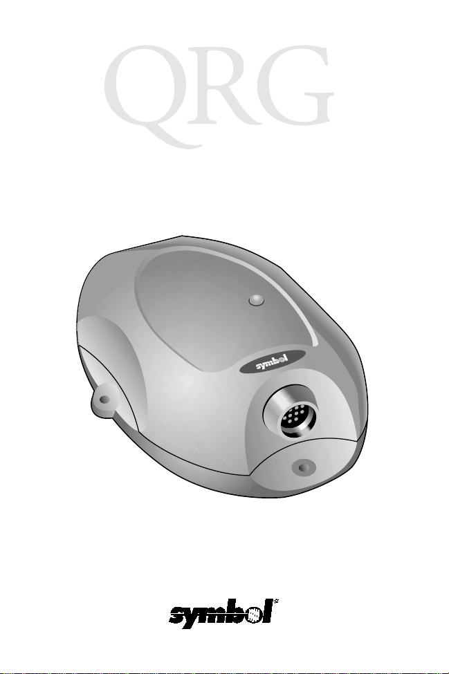
The FL-370-1000CC RF Forkl ift base is a commu nication cond uit
between the Phaser RF scanner and forklift moun ted term in al. It
is a sealed device designed to be mounted on a forklift. The RF
Forklift base receives data from the scanner via radio frequency
(RF) transmissions through its antenna, then transmits that d ata to
the forklift vehicle mounted terminal through an attache d cab le.
Quick Reference Guide
This
up and use of the RF Forklift base.
Unpacking the Radio Base
The shipping box includes the following:
• Fully sealed RF Forklift base
• Four screws (see page 3 for mounting)
• This Quick Reference Gui de (p/n 72-52373-xx)
• Radio Base mounting template (page 13)
Note: The Interface cable m ust be purchased separately.
Save the shipp ing container for s toring or shippi ng. Inspect all your
equipment for damage. If any th ing is damaged or missing, call
your authorized Customer Support Representative immediately.
provides basic instruct ion on the se t
1
FL370-I000CC
RF Forklift Base
About This Guide
This guide provides instructions for the foll ow ing:
• “Mounting the Radio Base” on page 3
• “Connecting to the Host” on page 3
• “Connector Pinout” on page 5
• “Pairing” on page 6
• “Spectrum 24 Environment” page 6
• “LED Indicator” on page 8
• “Cleaning the Base” on page 8
• “Troubleshooting” on page 8
• “Service Information” o n page 14
• “Warranty” on page 12
• “Mounting Template” on page 13 .
LED Light
Mounting Holes
Interface Cable
Connector
2
Quick Reference
r
Mounting the Base
1. Mount the RF Forklift base on a flat
surface free of dirt and oi l and three
feet or more from an RF terminal’s
radio antenna.
2. Fasten the four screws provided
through the RF Forklift base and
into the mounting area. A mounting
template is provided for you on page
13.
3. Install the cable by aligning the alignment tab and firmly
pushing the cable into the connector.
Mounting Holes
Connecting to the Host
Note: The RF Forklift base power con-
sumption is 200mA maximum.
Interface Cable Connecto
3

FL370-I000CC
RF Forklift Base
Symbol Vehicle Mounted Terminals
To connect the radio base to a forklift vehicle mounted terminal:
1. Install the appr opriate interf ace cab le between the hos t computer and the RF Forklift base connector.
Note: Commonly used c ables which include RS232 and
scanner emulation cables are available.
2. Communication between the scanner and the RF Forklift
base is establishe d through the pa iring procedu re (see page
6).
3. The VRC terminal su pplies po wer to t he RF F orklift base using the appropriate interfa ce ca ble .
Other Vehicle Mounted Terminals
1. Install the appr opriate interf ace cab le between the hos t computer and the base’s connec tor.
2. The terminal or a separately sold Symbol external power
supply provides po w er to the RF Fork lift base using the ap propriate interface cable.
4

Quick Reference
Connector Pinout
12
1
4
3
5
11
10
9
Pin
Number
1 Command Mode 7 Transmit Data
2 5 Volt Supply 8 Data Terminal
3 Ground (When
4 Synapse Data 10 Request to Send
5 Synapse Clock 11 Ground (W hen
6 Receive Data
Function Pin Number Function
Using 5 Volt
Supply
(RXD)
2
6
7
8
(TXD)
Ready (DTR)
9 Clear to Send
(CTS)
(RTS)
Using 9 Volt
Supply
12 9-12 Volt Supply
5

FL370-I000CC
RF Forklift Base
Pairing
The scanner and RF Forklift base must be paired for
communication to occur.
Note: If a new host is connected to the RF Forklift base,
rescan the pairing bar code on the top of the unit
again.
To pair the scan ner with the RF For klift base:
1. Scan the pairing bar cod e on the top or bottom of t he
RF Forklift base.
2. The scanner may briefly display the “pairing search for
channel” message while the scanner searches for the
base. Once the base is detec ted, infor mati on is ex changed (addressing, RF channels, etc.) between the
scanner and the cradle.
It may take up to 30 seconds for the
Note:
scanner to search for th e base
during over-the-air pairing.
3. After the exchange is complete, the scanner and cradle are paired. Successful pairing is indicated by a
warble beep and the base’s LED will flash; failure, or
an unsuccessful link, i s indi cated by a Lo Hi beep.
The pairing of a scanner to a cradle is one-to-one. Only one
scanner can be paired to a cradle at any point in time. If you
pair a second scanner to an in us e cradl e, the cradl e’s
connection to the first scanner will be broken and the
connection re-established with the second scanner.
6

Quick Reference
To pair a scanner to a different cradle, scan its pairing bar
code located on the top of the cradle.
Coexistence in Spectrum24 Env ironme nts
If you operate your scanner or cradle in close proximity to a
Spectrum24 device, maintain a buffer of 3 feet or greater
between the transmitter s . A Sp ec tru m24 de vi ce includes
but is not limited to a terminal with a Spectrum24 radio, PC
with a Spectrum24 card, or a Spectrum24 Access Point. If
a scanner or cradle is les s than 3 ft. from a 2.4 G Hz
Spectrum24 transmitter (antenna), especially an Ac c es s
Point, your communication performance may degrade
significantly.
Select a Channel Outside the Spectrum24 band
In the unlikely event that S24 radio traffic does cause
interference between the scanner and radio base, you can
change the base’s radio channel to one that minimizes or
eliminates interf er ence.
Phaser cordless scanners have three channels that are not
within the Spectrum24 band, 81, 82, and 83*. As a rule of
thumb, the Cordless systems closest to Spectrum24
devices should use these channels.
In applications with low scanning / data transmission duty
cycles, you may assign the same channel to more than one
Phaser.
After channels 81, 82 and 83, the next best channels to use
are 60 through 80; the higher the channel the better.
* Not available in some co untr i es.
7

FL370-I000CC
RF Forklift Base
Increase the number of RF Retries
If the scanner transmis sion is not re ceived b y the RF Forkl ift base
or the base acknow ledgment response is not received by the
scanner, the scanner retransmits the lost or corrupted data. The
scanner attempts 4 RF Retries (de f aul t) but can be prog ram me d
to attempt up to 8.
Depending on your particular RF environment, additional retries
may cause your scanner transaction ti me to increase in the
presence of heavy Spectrum24 traffic.
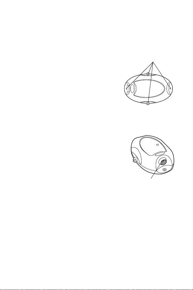
Radio Base LED Indicator.
LED Status Description
Off No scan signal received by base.
On Radio Base receiving scan signal.
Cleaning
The RF Forklift base meets IP 65 speci fications and is sealed
against dust and water . The R F Forklift base can be w ashed down
along with the forklift using a low pressure water source.
Troubleshooting
If the RF Forklift base does not work after you’ve followed these
operating instructions:
• Check the system power.
• Check for loose cable connections.
8

Quick Reference
Regulatory Information
Radio Frequency Interference Requirements
This device has been tested and found to comply with the limits for a Class A digital device pursuant
to Part 15 of the Federal Comm unicat ions Co mmission s Rules and Regulation. These limits are
designed to provide reasonable protection against harmful interference when the equipment is
operated in a commercial environment. This equipment generates, uses, and can radiate radio
frequency energy and, if not installed and used in accordance with the instruction manual, may
cause harmful interference to radio communications. Ope ration of this equipment in a residential
area is likely to cause harmful interference in which case the user will be required to correct the
interference at his own expense.
However, there is no guarantee that interference will not occur in a particular installation. If the
equipment does cause harmful interference to radio or television reception, which can be
determined by turning the equipment off and on, the user is encouraged to try to correct the
interference by one or more of the following measures:
• Re-orient or relocate the receiving antenna.
• Increase the separation between the equipment and receiver.
• Connect the equipment into an outlet on a circuit different from that which the receiver is connected.
• Consult the dealer or an experienced radio/TV technician for help.
This device complies with FCC Part 15. Operation is subject to the following two conditions: (1) t his
device may not cause harmful interference and (2) this device must accept any interference
received, including interference that may cause undesired operation.
Radio Frequency Interference Requirements - Canada
This Class A digital apparatus meets the requirements of the Canadian Interference-Causing
Equipment Regulations.
Cet appareil numérique d e la Classe A respecte t outes les exi gences du Reglement su r le Mate riél
Brouilleur du Canada.
This Class B digital apparatus complies with Canadian ICES-003.
Cet appareil numérique de la classe B est conforme à la norme NMB-003 du Canada.
European Economic Area
The European variant is intended for use throughout the European Economic Area, however
authorization for use is restricted to as follows:
European Economic Area-Frequency Range 2.400 - 2.4835 GHz.
France - Frequency Range 2.4465 - 2.454 GHz.
Belgium (outside) - Frequency Range 2.460 - 2.4835.
Italy - Operation requires a user license.
CE Marking and European Union Compliance
Applicable Directives
• Electromagnetic Compatibility Directive 89/336/EEC
• Low Voltage Directive 73/23/EEC
Products intended for sale within the Europea n Union are marked with the CE Mark
which indicates compliance to applicable Directives and European Normes (EN), as
follows. Amendments to these Directives or ENs are included:
9

FL370-I000CC
RF Forklift Base
DECLARATION OF CONFORMITY
We, Symbol Technologies, Inc.
of One Symbol Plaza, Holtsville, NY 11742-1300, USA
declare under our sole responsibility that the product(s)
FL370 RF Forklift Base
to which this declaration relates, is in conformity with the following standards and/or other normative documents.
I-ETS 300 440 (December 1995)
ETS 300 683 (June 1997)
EN 60950: 1992 Incl Amdt 1-4, 11
We hereby declare that all essential radio test suites have been carried out and that the above named product(s) is in
conformity with all the essential requirements of Directive 1999/5/EC.
The conformity assessment procedure referred to in Article 10(5) and detailed in Annex IV of
Directive 1999/5/EC has been followed with the involvement of the following Notified Body(ies):
BABT, Claremont House, 34 Molesey Road, Walton-on-Thames, KT12 4RQ
Identification mark: 0168 The equipment will also carry the Class
The technical documentation relevant to the above equipment can be made available for
inspection on application to:
Symbol Technologies EMEA, Symbol Place, Winnersh Triangle, Berkshire, RG 41 5TP, UK
Dornu Narnor
(name)
Director, Regulatory and Technical Sales
(title)
(signature of authorised person) (date)
2 equipment identifier
3, May 2000
10

Quick Reference
Applicable Standards
• EN 300 440: 1999 - Electromagnetic and Radio Spectrum Matter (ERM) Sh ort Ran ge
De v ices: Technical Characteristics and Test Met hods for Radio Equipment to be Used in the
1 GHz to 40 GHz Frequency Range.
• ETS 300 683: 1997 - Radio Equipment and System (RES); Electromagnetic Compatibility
(EMC) Standard for Short Range Devices (SRD) Operating on Frequencies between 9kHz
and 25 GHz.
• EN 1000-4-2: 1995/EN 61000-4-2:1995 - Electromagnetic Compatibility (EMC); Part 4: Testing and Measurement Techniques; Section 4.2: Electrostatic Discharge Immunity Test.
• EN 61000-4-3: 1997 - Electromagnetic Compatibility (EMC); Part 4 Testing and Measurement Techniques; Section 3: Radiated, Radio Frequency, Electromagnetic Field Immunity
Test.
• IEC 1000-4-4: 1995/EN 61000-4-4: 1995 - Electromagnetic Compatibility (EMC); Part 4:
Testing and Measurement Techniques; Section 4: Testing Electrical Fast Transient, Burst
Immunity.
• IEC 1000-4-5: 1995/EN 61000-4-5: 1995 - Electromagnetic Compatibility (EMC); Part 4:
Testing and Measurement Techniques; Section 5 : Surge Immunity.
• IEC 1000-4-6: 1996/EN 61000-4-6: 1996 - Electromagnetic Compatibility (EMC); Part 4:
Testing and Measurement Techniques; Section 6: Immunity to Conducted Disturbances,
Induced by Radio Frequency Fields.
• IEC 1000-4-11: 1994/EN 61000-4-11: 1994 - Electromagnetic Compatibility (EMC); Part 4:
Testing and Measurement Techniques; Section 11: Voltage Dips, Short Interruptions and
Voltage Variations.
RF Devices
Symbol’s RF products are designed to be co mpli ant with the rule s and regu lations in the location s
into which they are sold and will be labeled as required. The majority of Symbol’s RF devices are
type approved and do not require the user to obtain license or authorization before using the
equipment. Any changes or modifications to Symbol Technologies equipment not expressly
approved by Symbol Technologies could void the user’s authority to operate the equipment.
Caution: RF Exposure Guidlines
To comply with FCC RF exposure requirements, antennas that are mounted externally at remote
locations or operating near users at stand-al one desktop or similar configurati ons must operate with
a minimum separation distance of 20 cm from all persons.
11

FL370-I000CC
RF Forklift Base
Warranty
Symbol Technologies, Inc. (“Symbol”) manufactures its hardware products in accordance with
industry-standard practices. Symbol warrants that for a period of twelve (12) months from date of
shipment, products will be free from defects in materials and workmanship.
This warranty is provided to th e ori ginal owner only an d is not tr ansferable to any thir d party. It shall
not apply to any product (i) whi ch has been repair ed or altered un less done or appr oved by Symbol,
(ii) which has not been maintained in accordance with any operating or handling instructions
supplied by Symbol, (iii) which has been subjected to unusual physical or electrical stre ss, misuse,
abuse, power shortage, negligence or accident or (iv) which has been used other than in
accordance with the product operating and handling instructions. Preventive maintenance is the
responsibility of customer and is not covered under this warranty.
Wear items and accessories having a Symbol serial number, will carry a 90-day limited warranty.
Non-serialized items will carry a 30-day limited warranty.
Warranty Coverage and Procedure
During the warranty period, Symbol will repair or replace defective products returned to Symbol’s
manufacturing plant in the US. For warranty service in North America, call the Symbol Support
Center at 1-800-653-5350. International customers should contact the local Symbol office or
support center. If warranty service is required, Symbol will issue a Return Material Authorization
Number. Products mu st be shipped in the original or comparable packaging, shipping and
insurance charges prepaid. Symbol will ship the repaired or replacement product freight and
insurance prepaid in North America. Shipments from the US or other locations will be made F .O.B.
Symbol’s manufacturing plant.
Symbol will use new or refurbished parts at its discretion and will own all parts removed from
repaired products. Customer will pay for the replacement product in case it does not return the
replaced product to Symbol within 3 days of receipt of the replacement product. The process for
return and customer’s charges will be in accordance with S ymbol’ s Exchange P olicy in ef fect at th e
time of the exchange.
Customer accepts full responsibility for its software and data including the appropriate backup
thereof.
Repair or replacement of a product during warranty will not extend the original warranty term.
Symbol’s Customer Service organizat ion offers an array of service plans, such as on-site, depot, or
phone support, that can be implemented to meet customer’s special operati onal requirements and
are available at a substantial discount during warranty period.
General
Except for the warranties stated above, Symbol disclaims all warranties, express or implied, on
products furnished hereunder , incl uding without lim itation implied w arranties of mer chantability and
fitness for a particular purpose. The stated express warranties are in lieu of all obligations or
liabilities on part of Symbol for damages, including without limitation, special, indirect, or
consequential damages arising out of or in connection with the use or perfor mance of the product.
Seller’s liability for damages to buyer or other s resulting from the u se of any product, sha ll in no way
exceed the purchase price of said product, except in instances of injury to persons or property.
Some states (or jurisdiction s) do n ot allow the exclusion or l im itati on o f incidental or consequ ential
damages, so the proceeding exclusion or limitation may not apply to you.
12

Quick Reference
Mounting Dimensions
Not to actual size.
5.819”
3.756”
13

Service Information
Before you use the unit, it must be configured to operate in your facility’s network and
run your applications.
If you have a problem running your unit or using your equipment, contact your
facility’s T echnical or Systems Support. If there is a problem with the equipment, they
will contact the Symbol Support Center:
United States 1-800-653-5350 Ca na da 905-629-7226
United Kingdom 0800 328 2424 Asia/Pacific 337-6588
Australia 1-800-672-906 Austria 1-505-5794
Denmark 7020-1718 Finland 9 5407 580
France 01-40-96-52-21 Germany 6074-49020
Italy 2-484441 Mexico 5-520-1835
Netherlands 315-271700 Norway 66810600
South Africa 11-4405 668 Spain 913244000
Sweden 84452900
Latin America Sales Support 1-800-347-0178 In side U S
Europe/Mid-East Distributor Operations Contact local distributor or call
+1-561-483-1275 Outside US
+44 208 945 7360
72-52373-01
Revision B — August 2001
Symbol Technologies, Inc. One Symbol Plaza Holtsville, NY 11742-1300
 Loading...