


MC93XX
Mobile Computer
Integrator Guide
MN-003445-06 Rev A

Copyright
ZEBRA and the stylized Zebra head are trademarks of Zebra Technologies Corporation, registered in many
jurisdictions worldwide. Google, Android, Google Play and other marks are trademarks of Google LLC; Oreo is
a trademark of Mondelez International, Inc. group. All other trademarks are the property of their respective
owners. ©2021 Zebra Technologies Corporation and/or its affiliates. All rights reserved.
COPYRIGHTS & TRADEMARKS: For complete copyright and trademark information, go to www.zebra.com/
copyright.
WARRANTY: For complete warranty information, go to www.zebra.com/warranty
END USER LICENSE AGREEMENT: For complete EULA information, go to www.zebra.com/eula
Terms of Use
• Proprietary Statement
This manual contains proprietary information of Zebra Technologies Corporation and its subsidiaries
(“Zebra Technologies”). It is intended solely for the information and use of parties operating and maintaining
the equipment described herein. Such proprietary information may not be used, reproduced, or disclosed to
any other parties for any other purpose without the express, written permission of Zebra Technologies.
• Product Improvements
Continuous improvement of products is a policy of Zebra Technologies. All specifications and designs are
subject to change without notice.
• Liability Disclaimer
Zebra Technologies takes steps to ensure that its published Engineering specifications and manuals are
correct; however, errors do occur. Zebra Technologies reserves the right to correct any such errors and
disclaims liability resulting therefrom.
• Limitation of Liability
In no event shall Zebra Technologies or anyone else involved in the creation, production, or delivery of the
accompanying product (including hardware and software) be liable for any damages whatsoever (including,
without limitation, consequential damages including loss of business profits, business interruption, or loss of
business information) arising out of the use of, the results of use of, or inability to use such product, even if
Zebra Technologies has been advised of the possibility of such damages. Some jurisdictions do not allow
the exclusion or limitation of incidental or consequential damages, so the above limitation or exclusion may
not apply to you.
.
.
Revision History
Changes to the original guide are listed below:
Change Date Description
-01 Rev A 03/2019 Initial release.
-02 Rev A 07/2019 Updated to include MC93XX freezer configuration.
-03 Rev A 10/2019 Updated to include SE4750 Direct Part Marking (DPM)/Direct Part Marking - Wide
-04 Rev A 02/2020 Updated Installing a microSD Card section with supported SD cards.
-05 Rev A 04/2020 Added Decode Zone specifications.
-06 Rev A 10/2021 Updated GMS Restricted topic.
(DPW), SE4770 scanner, and additional keypads.
2

Table of Contents
Copyright ......................................................................................................................... 2
Terms of Use .................................................................................................................. 2
Revision History .............................................................................................................. 2
About This Guide........................................................................................................ 11
Introduction ................................................................................................................... 11
Documentation Set ....................................................................................................... 11
Configurations .............................................................................................................. 12
Software Versions ......................................................................................................... 12
Chapter Descriptions .................................................................................................... 13
Notational Conventions ................................................................................................. 13
Related Documents ...................................................................................................... 14
Service Information ....................................................................................................... 14
Provide Documentation Feedback ................................................................................ 15
Getting Started............................................................................................................ 16
Introduction ................................................................................................................... 16
Unpacking ..................................................................................................................... 16
Setting Up the Device ................................................................................................... 16
Installing a microSD Card ...................................................................................... 17
Charging the Device .............................................................................................. 22
Charging the Main Battery .............................................................................. 23
Backup Power ....................................................................................................... 24
Hot Swap Mode ..................................................................................................... 24
Removing and Replacing Keypads ............................................................................... 24
Accessories................................................................................................................. 28
Introduction ................................................................................................................... 28
MC93XX Accessories ................................................................................................... 28
1-Slot USB Charge Cradle with Spare Battery Charger .............................................. 32
3

Table of Contents
Setup ..................................................................................................................... 32
Charging the Device .............................................................................................. 32
Charging Temperature .................................................................................................. 34
4-Slot Charge Only ShareCradle ................................................................................. 35
Setup ..................................................................................................................... 35
Charging the Devices ...................................................................................... 35
Charging Temperature .................................................................................... 36
4-Slot Ethernet ShareCradle ........................................................................................ 37
Setup ..................................................................................................................... 37
Charging the Devices ...................................................................................... 37
Daisy-chaining Ethernet ShareCradles ................................................................. 38
Ethernet Settings ............................................................................................ 39
Configuring Ethernet Proxy Settings ............................................................... 39
Configuring Ethernet Static IP Address .......................................................... 40
Establishing Ethernet Connection ......................................................................... 41
LED Indicators ....................................................................................................... 42
Charging Temperature .................................................................................... 42
16-Slot Spare Battery Charger ..................................................................................... 43
Setup ..................................................................................................................... 43
Charging the Spare Batteries .......................................................................... 43
Charging Temperature .................................................................................... 44
USB Charge/Com Snap-on Cup .................................................................................. 45
Connecting to the Device .................................................................................................. 45
Connecting the USB Charge/Com Snap-on Cup Cable to Host Computer ........... 46
Charging the Device .............................................................................................. 47
Disconnecting the USB Charge/Com Snap-on Cup .............................................. 47
MC93XX Charge Only Adapter ....................................................................... 48
Charge Only Adapter Installation .......................................................................... 49
Rubber Boot ................................................................................................................. 52
Installing the Hand Strap .............................................................................................. 54
4-Slot Charge Only ShareCradle Rack Installation ...................................................... 55
Rack Mount Installation ................................................................................................ 59
Wall Installation ............................................................................................................ 62
Bottom Tray Assembly .......................................................................................... 62
Bracket Wall Mounting .......................................................................................... 62
Settings........................................................................................................................ 64
Introduction ................................................................................................................... 64
WLAN Configuration ..................................................................................................... 64
Configuring a Secure Wi-Fi Network ..................................................................... 64
Manually Adding a Wi-Fi Network ......................................................................... 65
Configuring for a Proxy Server .............................................................................. 66
4

Table of Contents
Configuring the Device to Use a Static IP Address ............................................... 67
Wi-Fi Preferences .................................................................................................. 68
Additional Wi-Fi Settings ....................................................................................... 69
Wi-Fi Direct ............................................................................................................ 69
WPS Push Button .................................................................................................. 70
WPS Pin Entry ....................................................................................................... 71
Setting Screen Lock .............................................................................................. 71
Setting Screen Lock Using PIN ............................................................................. 72
Setting Screen Unlock Using Password ................................................................ 72
Setting Screen Unlock Using Pattern .................................................................... 73
Showing Passwords .............................................................................................. 74
Remapping a Button ..................................................................................................... 74
Accounts ....................................................................................................................... 75
Language Usage ........................................................................................................... 76
Changing the Language Setting ............................................................................ 76
Adding Words to the Dictionary ............................................................................. 76
Keyboard Settings ................................................................................................. 76
PTT Express Configuration ........................................................................................... 76
RxLogger ...................................................................................................................... 76
RxLogger Configuration ........................................................................................ 77
RxLogger Settings .......................................................................................... 78
ANR Module .......................................................................................................... 78
Kernel Module ................................................................................................. 78
Logcat Module ................................................................................................ 79
LTS Module ..................................................................................................... 80
Ramoops Module ............................................................................................ 80
Resource Module ............................................................................................ 81
Snapshot Module ............................................................................................ 81
TCPDump Module .......................................................................................... 82
Tombstone Module ......................................................................................... 82
Configuration File .................................................................................................. 82
Enabling Logging ................................................................................................... 82
Disabling Logging .................................................................................................. 82
Extracting Log Files ............................................................................................... 83
RxLogger Utility ............................................................................................................. 83
App View ............................................................................................................... 83
Viewing Logs ................................................................................................... 83
Backup ............................................................................................................ 85
Archive Data ................................................................................................... 85
Overlay View ......................................................................................................... 85
Initiating the Main Chat Head .......................................................................... 85
Removing the Main Chat Head ....................................................................... 86
Viewing Logs ................................................................................................... 86
5

Table of Contents
Removing a Sub Chat Head Icon ................................................................... 87
Backing Up In Overlay View ........................................................................... 87
About Phone ................................................................................................................. 87
USB Communication .................................................................................................. 89
Introduction ................................................................................................................... 89
Transferring Files with a Host Computer via USB ........................................................ 89
Transferring Files .......................................................................................................... 89
Transferring Photos ............................................................................................... 90
Disconnect from the Host Computer ..................................................................... 90
DataWedge .................................................................................................................. 91
Introduction ................................................................................................................... 91
Basic Scanning ............................................................................................................. 91
Barcode Capture with Imager ................................................................................ 91
Profiles .......................................................................................................................... 92
Profile0 .................................................................................................................. 92
Plug-ins ......................................................................................................................... 92
Input Plug-ins ........................................................................................................ 93
Process Plug-ins ................................................................................................... 93
Output Plug-ins ...................................................................................................... 93
Profiles Screen .............................................................................................................. 93
Profile Context Menu ............................................................................................. 94
Options Menu ........................................................................................................ 94
Disabling DataWedge ............................................................................................ 95
Creating a New Profile .................................................................................................. 95
Profile Configuration ..................................................................................................... 95
Associating Applications ........................................................................................ 96
Data Capture Plus ................................................................................................. 98
Barcode Input ...................................................................................................... 100
Enabled ......................................................................................................... 100
Scanner Selection ......................................................................................... 100
Auto Switch to Default on Event ................................................................... 100
Configure Scanner Settings .......................................................................... 101
Decoders ....................................................................................................... 101
Decoder Params ................................................................................................. 104
UPC EAN Params ......................................................................................... 109
Reader Params ............................................................................................. 112
Scan Params ................................................................................................ 115
UDI Params .................................................................................................. 116
Multibarcode params .................................................................................... 116
Keep enabled on suspend ............................................................................ 116
6

Table of Contents
Voice Input .......................................................................................................... 116
Keystroke Output ................................................................................................. 117
Intent Output ........................................................................................................ 118
Intent Overview ............................................................................................. 119
IP Output ............................................................................................................. 120
Usage ............................................................................................................ 121
Using IP Output with IPWedge ..................................................................... 122
Using IP Output without IPWedge ................................................................ 123
Generating Advanced Data Formatting Rules ............................................................ 124
Configuring ADF Plug-in ...................................................................................... 124
Creating a Rule ............................................................................................. 125
Defining a Rule ............................................................................................. 125
Defining Criteria ............................................................................................ 126
Defining an Action ......................................................................................... 127
Deleting a Rule ............................................................................................. 128
Order Rules List ............................................................................................ 128
Deleting an Action ......................................................................................... 129
ADF Example ................................................................................................ 129
DataWedge Settings ................................................................................................... 132
Importing a Configuration File ............................................................................. 133
Exporting a Configuration File ............................................................................. 134
Importing a Profile File ........................................................................................ 134
Exporting a Profile ............................................................................................... 134
Restoring DataWedge ......................................................................................... 134
Configuration and Profile File Management ................................................................ 135
Enterprise Folder ................................................................................................. 135
Auto Import .......................................................................................................... 135
Programming Notes .................................................................................................... 135
Capture Data and Taking a Photo in the Same Application ................................ 135
Disable DataWedge on Device ........................................................................... 136
Reporting ............................................................................................................. 136
Soft Scan Trigger ................................................................................................ 136
Function Prototype ........................................................................................ 136
Parameters .......................................................................................................... 136
Scanner Input Plugin ........................................................................................... 137
Function Prototype ........................................................................................ 137
Parameters ................................................................................................... 137
Return Values ............................................................................................... 137
Example ........................................................................................................ 138
Comments ..................................................................................................... 138
Enumerate Scanners ........................................................................................... 138
Function Prototype ........................................................................................ 138
Parameters ................................................................................................... 138
Return Values ............................................................................................... 139
7

Table of Contents
Example ........................................................................................................ 140
Comments ..................................................................................................... 140
Set Default Profile ............................................................................................... 141
Default Profile Recap .................................................................................... 141
Usage Scenario ............................................................................................ 141
Function Prototype ........................................................................................ 141
Parameters ................................................................................................... 141
Return Values ............................................................................................... 141
Example ........................................................................................................ 142
Comments ..................................................................................................... 142
Reset Default Profile ........................................................................................... 142
Function Prototype ........................................................................................ 143
Parameters ................................................................................................... 143
Return Values ............................................................................................... 143
Example ........................................................................................................ 143
Comments ..................................................................................................... 143
Switch To Profile ................................................................................................. 144
Profiles Recap ............................................................................................... 144
Usage Scenario ............................................................................................ 144
Function Prototype ........................................................................................ 144
Parameters ................................................................................................... 144
Return Values ............................................................................................... 145
Example ........................................................................................................ 145
Comments ..................................................................................................... 145
Notes ............................................................................................................. 146
Application Deployment........................................................................................... 147
Introduction ................................................................................................................. 147
Security ....................................................................................................................... 147
Secure Certificates ...................................................................................................... 147
Installing a Secure Certificate ..................................................................................... 147
Configuring Credential Storage Settings ............................................................. 148
Development Tools ..................................................................................................... 148
Android Application Development ....................................................................... 148
Development Workstation ............................................................................. 148
Target Device ................................................................................................ 149
EMDK for Android ............................................................................................... 149
StageNow ............................................................................................................ 149
GMS Restricted ........................................................................................................... 149
ADB USB Setup .................................................................................................. 150
Enabling USB Debugging ........................................................................................... 150
Application Installation ................................................................................................ 150
Using Android Studio .................................................................................................. 151
Installing Applications Using the USB Connection .............................................. 151
8

Table of Contents
Installing Applications Using the Android Debug Bridge ..................................... 152
Installing Applications Using a microSD Card ..................................................... 153
Uninstalling an Application .................................................................................. 154
Performing a System Update ...................................................................................... 155
Downloading the System Update Package ......................................................... 155
Using microSD Card ............................................................................................ 155
Using ADB ........................................................................................................... 156
Verify System Update Installation ....................................................................... 157
Performing an Enterprise Reset .................................................................................. 157
Downloading the Enterprise Reset Package ....................................................... 157
Using microSD Card ............................................................................................ 157
Using ADB ........................................................................................................... 158
Performing a Factory Reset ........................................................................................ 159
Downloading the Factory Reset Package ........................................................... 159
Using microSD Card ............................................................................................ 159
Using ADB ........................................................................................................... 160
Storage ....................................................................................................................... 160
Random Access Memory .................................................................................... 161
Internal Storage ................................................................................................... 161
External Storage .................................................................................................. 162
Formatting a microSD Card as Portable Storage ......................................... 163
Formatting a microSD Card as Internal Memory .......................................... 164
Enterprise Folder ................................................................................................. 166
App Management ........................................................................................................ 166
Viewing App Details ............................................................................................ 167
Managing Downloads ................................................................................................. 167
Maintenance and Troubleshooting ......................................................................... 169
Introduction ................................................................................................................. 169
Maintaining the Device ................................................................................................ 169
Battery Safety Guidelines ........................................................................................... 169
Cleaning Instructions .................................................................................................. 170
Approved Cleanser Active Ingredients ................................................................ 170
Harmful Ingredients ............................................................................................. 170
Device Cleaning Instructions ............................................................................... 171
Special Cleaning Notes ....................................................................................... 171
Cleaning Materials Required ............................................................................... 171
Cleaning Frequency ............................................................................................ 171
Cleaning the Device ............................................................................................ 171
Housing ......................................................................................................... 171
Display .......................................................................................................... 171
9

Table of Contents
Exit Window .................................................................................................. 172
Cleaning Battery Connectors .............................................................................. 172
Cleaning Cradle Connectors ............................................................................... 172
Troubleshooting .......................................................................................................... 173
MC93XX .............................................................................................................. 173
1-Slot USB Charge Cradle .................................................................................. 175
4-Slot Charge Only Cradle .................................................................................. 176
4-Slot Ethernet ShareCradle Troubleshooting .................................................... 177
4-Slot Spare Battery Charger Troubleshooting ................................................... 178
16-Slot Spare Battery Charger Troubleshooting ................................................. 178
USB Charge/Com Snap-on Cup Troubleshooting ............................................... 179
Specifications............................................................................................................ 180
Introduction ................................................................................................................. 180
MC93XX Technical Specifications .............................................................................. 180
SE965 Decode Zone ................................................................................................... 183
SE4750-SR Decode Zone ................................................................................... 185
SE4770-SR Decode Zone ................................................................................... 185
SE4850-ER Decode Zone ................................................................................... 186
I/O Connector Pin-Outs ....................................................................................... 187
MC93XX Accessory Specifications ............................................................................. 187
1-Slot USB Charge Cradle with Spare Battery Charger Technical Specifications 187
4-Slot Charge Only ShareCradle Technical Specifications ................................. 188
4-Slot Ethernet ShareCradle Technical Specifications ........................................ 188
4-Slot Spare Battery Charger Technical Specifications ...................................... 189
16-Slot Spare Battery Charger Technical Specifications .................................... 190
USB Charge/Com Snap-on Cup Technical Specifications .................................. 190
Index........................................................................................................................... 191
10

About This Guide
Introduction
This guide provides information about setting up and configuring the device and its accessories.
NOTE: Screens and windows pictured in this guide are samples and can differ from actual screens.
Documentation Set
The documentation set provides information for specific user needs, and includes:
• MC93XX Quick Start Guide - describes how to get the device up and running.
• MC93XX User Guide - describes how to use the device.
• MC93XX Integrator Guide - describes how to set up the device and accessories.
• MC93XX Regulatory Guide - provides all regulatory, service, and EULA information for the device.
11

Configurations
This guide covers the following configurations:
Table 1 Configurations
About This Guide
Configuration Radios Display Memory
MC93XX–G Base WLAN: IEEE 802.11
a/b/g/n/ac/d/h/i/r/w
WPAN: Bluetooth v5.0
Low Energy
Package 1
MC93XX–G Base +
NFC (Tap to Pair) +
Vibrator Motor
Package 2
Package 1 +
Front and Rear
Facing Cameras
MC93XX-G Freezer +
NFC (Tap to Pair) +
Vibrator Motor
WLAN: IEEE 802.11
a/b/g/n/ac/d/h/i/r/w
WPAN: Bluetooth v5.0
Low Energy
WLAN: IEEE 802.11
a/b/g/n/ac/d/h/i/r/w
WPAN: Bluetooth v5.0
Low Energy
WLAN: IEEE 802.11
a/b/g/n/ac/d/h/i/r/w
WPAN: Bluetooth v5.0
Low Energy
4.3" WVGA (800
x 480) LCD
4.3" WVGA (800
x 480) LCD
4.3" WVGA (800
x 480) LCD
4.3" WVGA (800
x 480) LCD.
Optically Bonded
to the Touch
Panel.
4 GB RAM /
32 GB Flash
4 GB RAM /
32 GB Flash
4 GB RAM /
32 GB Flash
4 GB RAM /
32 GB Flash
Data Capture
Options
SE965 1D,
SE4750-SR 2D,
SE4850-ER 2D
SE4750DPM
SE4750DPW
SE4770 2D
SE965 1D,
SE4750-SR 2D,
SE4850-ER 2D
SE4750DPM
SE4750DPW
SE4770 2D
SE965 1D,
SE4750-SR 2D,
SE4850-ER 2D
SE4770 2D
SE965 1D,
SE4750-SR 2D,
SE4850-ER 2D
SE4770 2D
Operating
System
Android-based
GMS 8.1.0
Android-based
GMS 8.1.0
Android-based
GMS 8.1.0
Android-based
GMS 8.1.0
Software Versions
To determine the current software versions:
1. Swipe down from the Status bar to open the Quick Settings bar.
2. Touch > System.
3. Touch About phone.
12

4. Scroll to view the following information:
• Status
• Battery information
• SW components
• Legal information
• Model
• Android version
• Android security patch level
• Kernel version
• Build Fingerprint
• Build number.
To determine the device serial number, touch About phone > Status.
• Serial number
Chapter Descriptions
About This Guide
Topics covered in this guide are as follows:
• Getting Started provides information on getting the device up and running for the first time.
• Accessories describes the available accessories and how to use them with the device.
• Settings provides the settings for configuring the device.
• USB Communication describes how to connect the device to a host computer using USB.
• DataWedge describes how to use and configure the DataWedge application.
• Application Deployment provides information for developing and managing applications.
• Maintenance and Troubleshooting includes instructions on cleaning and storing the device, and provides
troubleshooting solutions for potential problems during device operation.
• Specifications provides the technical specifications for the device.
Notational Conventions
The following conventions are used in this document:
• Bold text is used to highlight the following:
• Dialog box, window and screen names
• Drop-down list and list box names
• Check box and radio button names
• Icons on a screen
• Key names on a keypad
• Button names on a screen.
• Bullets (•) indicate:
• Action items
• Lists of alternatives
• Lists of required steps that are not necessarily sequential.
• Sequential lists (for example, those that describe step-by-step procedures) appear as numbered lists.
13

Related Documents
• MC93XX Quick Start Guide, p/n MN-003413-xx.
• MC93XX Regulatory Guide, p/n MN-003409-xx.
• MC93XX User Guide, p/n MN-003228-xx.
For the latest version of this guide and all guides, go to: www.zebra.com/support
Service Information
If you have a problem with your equipment, contact Customer Support for your region. Contact information is
available at: www.zebra.com/support
When contacting support, please have the following information available:
• Serial number of the unit (found on manufacturing label)
• Model number or product name (found on manufacturing label)
• Software type and version number
Customer Support responds to calls by email or telephone within the time limits set forth in support
agreements.
About This Guide
.
If the problem cannot be solved by Customer Support, you may need to return the equipment for servicing and
will be given specific directions. We are not responsible for any damages incurred during shipment if the
approved shipping container is not used. Shipping the units improperly can possibly void the warranty.Remove
the microSD card from the device before shipping for service.
If the device was purchased from a business partner, contact that business partner for support.
14

About This Guide
If the manufacturing label is worn or missing, use an NFC enabled device to read the NFC tag under the
battery compartment. You can download the NFC Reader application for free from the Google Play store.
Figure 1 Manufacturing Label Location
Manufacturing Label
NFC Tag (Inside the battery compartment.)
NFC Symbol
Provide Documentation Feedback
If you have comments, questions, or suggestions about this guide, send an email to
EVM-Techdocs@zebra.com
.
15

Getting Started
Introduction
This chapter provides information for getting the device up and running for the first time.
Unpacking
Carefully remove all protective material from the device and save the shipping container for later
storage and shipping.
Verify the following items are in the box:
• Device
• Lithium-ion battery
• Regulatory Guide.
Inspect the equipment for damage. If any equipment is missing or damaged, contact the Zebra
Support Center immediately.
Setting Up the Device
To start using the device for the first time:
1. Install a microSD card (optional)
2. Install the battery
3. Charge the device
4. Power on the device.
16

Installing a microSD Card
The microSD card slot provides secondary non-volatile storage. The slot is located under the keypad module.
Refer to the documentation provided with the card for more information, and follow the manufacturer’s
recommendations for use. It is strongly recommended that prior to use, you must format the microSD card on
the device.
NOTE: The following microSD cards were tested and are validated for use with the MC93XX:
• SanDisk 16GB (SDSDQ-016G-A11M)
• SanDisk 32GB (SDSDQ-032G-A11M)
• SanDisk 64GB (SDSDQUA-064G-U46A)
• SanDisk 128GB (SDSDQUI-128G-A46)
• SanDisk 200GB (SDSDQUAN-200G-A4A).
CAUTION: Follow proper electrostatic discharge (ESD) precautions to avoid damaging the microSD card. Proper ESD pre-
cautions include, but are not limited to, working on an ESD mat and ensuring that the operator is properly grounded.
1. Power off the device.
Getting Started
2. Remove the battery.
3. Using a Torx T8 screwdriver with a large grip, remove the two keypad latch screws from inside the battery
slot.
Figure 2 Remove Keypad Latch Screws
Keypad Latch Screws
17

Getting Started
4. Slide the keypad latches toward the bottom of the device.
Figure 3 Release Keypad Latches
Screwdriver
Keypad Latches
NOTE: If the keypad latches are hard to move, use a screwdriver to gently slide them towards the bottom of the device.
5. Turn the device over so that the keypad is visible.
6. Using a Torx T8 screwdriver with a large grip, remove the two keypad assembly screws from the top of the
keypad.
Figure 4 Remove Keypad
Keypad Screws
Keypad
microSD Card Holder
18

Getting Started
7. Lift the keypad from the device.
8. Slide the microSD card holder to the Open position.
Figure 5 Open microSD Card Holder
9. Lift the microSD card holder.
Figure 6 Lift microSD Card Holder
10.Insert the microSD card into the card holder door ensuring that the card slides into the holding tabs on each
side of the door.
Figure 7 Insert microSD Card into Holder
19

Getting Started
11.Close the microSD card holder door and slide the door to the Lock position.
Figure 8 Close and Lock microSD Card in Holder
12.Align the keypad along the bottom ridge of the device, and then lay it flat.
Figure 9 Replace Keypad
20

Getting Started
13.Using a Torx T8 screwdriver with a large grip and a long shaft, secure the keypad to the device using the
two screws. Torque screws to 5.8 kgf-cm or 5.0 lbf-in.
Figure 10 Replace Keypad Screws
Keypad Screws
14.Turn the device over so that the keypad latches are visible.
15.Slide both the keypad latches toward the top of the device.
Figure 11 Slide Keypad Latches
Keypad Latches
21

Getting Started
16.Using a Torx T8 screwdriver, replace the two keypad latch screws inside the battery slot and torque to 5.8
kgf-cm or 5.0 lbf-in.
Figure 12 Replace Keypad Latch Screws
Keypad Latch Screws
17.Insert the battery.
18.Press and hold the Power key to power on the device.
Charging the Device
Use one of the following accessories to charge the battery.
Table 2 Charging and Communication
Description Part Number
1-Slot USB Charge Cradle with
Spare Battery Charger
4-Slot Charge Only
ShareCradle
4-Slot Spare Battery Charger SAC-MC93-4SCHG-01 No Yes No No
4-Slot Ethernet ShareCradle CRD-MC93-4SETH-01 Yes No No Yes
16-Slot Spare Battery Charger SAC-MC93-16SCHG-01 No Yes No No
Charging Communication
Battery
(In
Device)
CRD-MC93-2SUCHG-01 Yes Yes Yes No
CRD-MC93-4SCHG-01 Yes No No No
Spare
Battery
USB Ethernet
USB Charge/Com Snap-on Cup
NOTE: A separate USB cable and
power supply is required to support
fast charging. USB (Type-C) Cable
is required to allow communication
from the snap-on to the PC/laptop.
Charge Only Adapter ADP-MC93-CRDCUP-01 Yes NA No No
CBL-MC93-USBCHG-01 Yes No Yes No
22

Getting Started
Charging the Main Battery
To charge the main battery:
1. Connect the charging accessory to the appropriate power source.
2. Insert the device into a cradle or attach a cable.
The device starts to charge automatically. The Charge LED Indicator indicates the charge status. See the
table below for charging indications.
Table 3 LED Charge Indicators
Status Indications
Off • The battery is not charging.
• The device is not inserted correctly in the cradle or connected to a
power source.
• Cradle is not powered.
Slow Blinking Amber
Every 3 seconds
• Battery is charging, but the battery is fully depleted and does not yet
have sufficient charge to power the device.
• After battery removal, indicates that the device is in hot swap mode with
connectivity persistence.
NOTE: The SuperCap requires a minimum of 15 minutes to fully charge in order to
provide adequate connectivity and memory session persistence.
Solid Amber • Battery is charging.
Solid Green • Battery charging is complete.
Fast Blinking Red
2 blinks/second
Solid Red • Battery is charging and battery is at the end of useful life.
The 7000mAh PowerPrecision+ standard battery charges from 0% to 90% in less than 3.5 hours at room
temperature using a Zebra accessory.
The 5000mAh PowerPrecision+ freezer battery charges from 0% to 90% in less than 2.5 hours at room
temperature using a Zebra accessory.
The 7000mAh PowerPrecision+ non-incendive battery charges from 0% to 90% in less than 3.5 hours at room
temperature using a Zebra accessory.
Charge batteries in temperatures from 0°C to 40°C (32°F to 104°F). The device or cradle always performs
battery charging in a safe and intelligent manner. At higher temperatures, for example at approximately +37°C
(+98°F), the device or cradle may for small periods of time alternately enable and disable battery charging to
keep the battery at acceptable temperatures. The device and cradle indicates when charging is disabled due to
abnormal temperatures via its LED.
Charging error. For example:
• Temperature is too low or too high.
• Charging has gone on too long without completion (typically eight
hours).
• Charging complete and battery is at the end of useful life.
23

Backup Power
The device is equipped with a super-capacitor (supercap) to provide backup power to the device when the
main battery is removed. The supercap will retain random access memory (RAM) data in memory for
approximately five minutes after the main battery is removed during Hot Swap.
IMPORTANT: The supercap is automatically charged from the main battery and requires approximately fifteen
minutes to fully charge.
Hot Swap Mode
The device provides a Hot Swap mode where you can replace the battery without powering off the device.
When you remove the battery, the display turns off and the devices enters the Hot Swap mode. WLAN and
Bluetooth connectivity are retained for the first 30 seconds (indicated by a flashing amber LED). After 30
seconds, the device enters a critical suspend mode with RAM data persistence for approximately 5 minutes. In
the critical suspend mode, WLAN and Bluetooth radios are disabled and will only resume if you insert a battery
with sufficient charge into the device.
CAUTION: To prevent damage to the device, DO NOT perform a hot swap during a device boot up session.
Getting Started
IMPORTANT: The supercap requires time to recharge after performing a Hot Swap or after the main battery is
fully depleted. It can take up to 15 minutes to fully charge the supercap. Hot Swap mode will not retain data
unless the supercap is fully charged.
Removing and Replacing Keypads
1. Power off the device.
2. Remove the battery.
3. Using a Torx T8 screwdriver with a large grip, remove the two keypad latch screws from inside the battery
slot.
Figure 13 Remove Keypad Latch Screws
24
Keypad Latch Screws

Getting Started
4. Slide the keypad latches toward the bottom of the device.
Figure 14 Release Keypad Latches
Screwdriver
Keypad Latches
NOTE: If the keypad latches are hard to move, use a screwdriver to gently slide them towards the bottom of the device.
5. Turn the device over so that the keypad is visible.
6. Using a Torx T8 screwdriver with a large grip, remove the two keypad assembly screws from the top of the
keypad.
Figure 15 Remove Keypad
Keypad Screws
Keypad
microSD Card Holder
25

Getting Started
7. Lift the keypad from the device.
8. Align the keypad along the bottom ridge of the device, and then lay it flat.
Figure 16 Replace Keypad
9. Using a Torx T8 screwdriver with a large grip and a long shaft, secure the keypad to the device using the
two screws. Torque screws to 5.8 kgf-cm or 5.0 lbf-in.
Figure 17 Replace Keypad Screws
Keypad Screws
10.Turn the device over so that the keypad latches are visible.
26
Getting Started
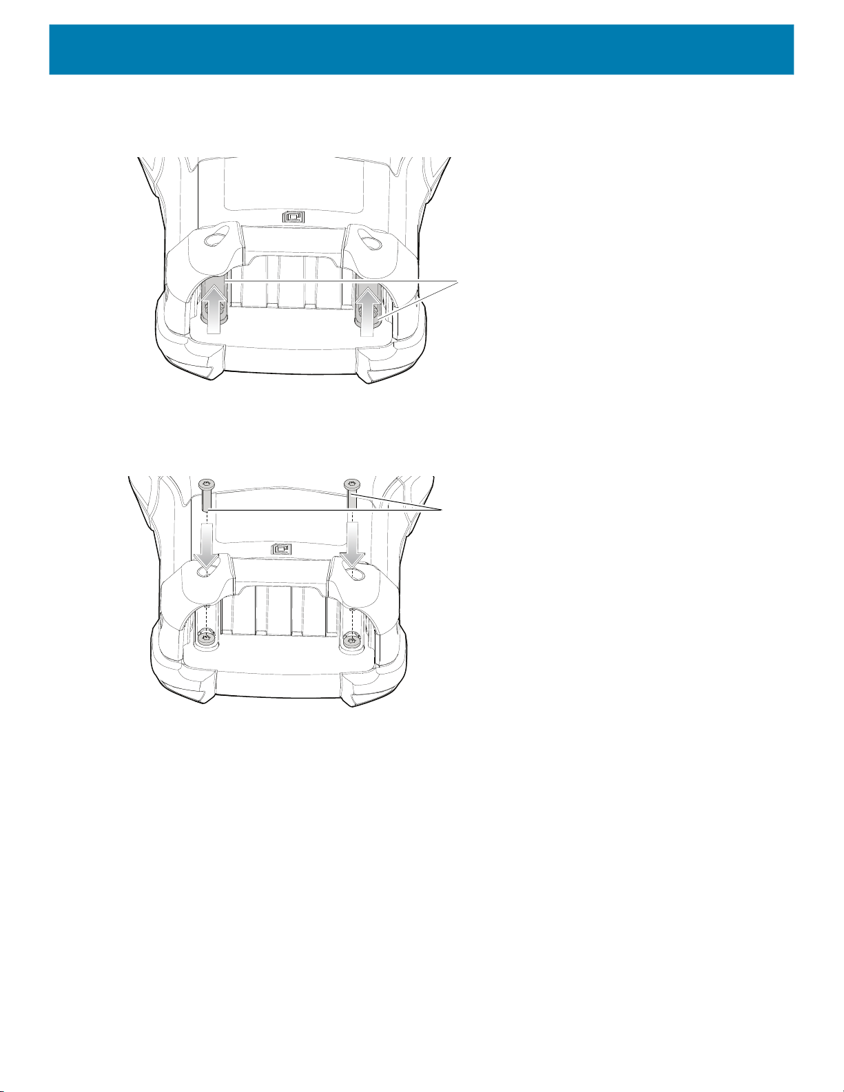
11.Slide both the keypad latches toward the top of the device.
Figure 18 Slide Keypad Latches
Keypad Latches
12.Using a Torx T8 screwdriver, replace the two keypad latch screws inside the battery slot and torque to 5.8
kgf-cm or 5.0 lbf-in.
Figure 19 Replace Keypad Latch Screws
Keypad Latch Screws
13.Insert the battery.
14.Press and hold the Power key to power on the device.
27

Accessories
Introduction
This chapter provides information for using the accessories for the device.
MC93XX Accessories
The table below lists the accessories available for the device.
Table 4 MC93XX Accessories
Accessory Part Number Description
Cradles
1-Slot USB Charge Cradle with Spare
Battery Charger
4-Slot Charge Only ShareCradle CRD-MC93-4SCHG-01 Charges up to four MC93XXs. Requires power
CRD-MC93-2SUCHG-01 Charges the MC93XX main battery and a spare
battery, and synchronizes the MC93XX with a
host computer through a USB connection.
Requires power supply
(PWR-BGA12V50W0WW), DC line cord
(CBL-DC-388A1-01) and a country specific
grounded AC line cord.
supply (PWR-BGA12V108W0WW), DC line cord
(CBL-DC-381A1-01) and a country specific
grounded AC line cord.
4-Slot Ethernet ShareCradle CRD-MC93-4SETH-01 Charges up to four MC93XXs through the main
battery and synchronizes the devices with a host
computer through an Ethernet connection.
Requires power supply
(PWR-BGA12V108W0WW), DC line cord
(CBL-DC-381A1-01) and a country specific
grounded AC line cord.
Chargers
4-Slot Spare Battery Charger SAC-MC93-4SCHG-01 Charges up to four MC93XX spare batteries.
Requires power supply
(PWR-BGA12V50W0WW), DC line cord
(CBL-DC-388A1-01) and a country specific
grounded AC line cord.
28

Accessories
Table 4 MC93XX Accessories (Continued)
Accessory Part Number Description
16-Slot Spare Battery Charger SAC-MC93-16SCHG-01 Charges up to 16 MC93XX spare batteries.
Requires power supply
(PWR-BGA12V108W0WW), DC line cord
(CBL-DC-381A1-01) and a country specific
grounded AC line cord.
Power Supply PWR-BGA12V50W0WW Provides 12 VDC, 4.16A power to the 1-Slot
USB Charge Cradle and the 4-Slot Spare Battery
Charger. Requires a DC line cord
(CBL-DC-388A1-01) and a country specific
grounded AC line cord.
Power Supply PWR-BGA12V108W0WW Provides 12 VDC, 9A power to the 4-Slot Charge
Cradle with 4-Slot Battery Charger, and 16-Slot
Battery Charger. Requires a DC line cord
(CBL-DC-381A1-01) and a country specific
grounded AC line cord.
Power Supply PWR-WUA5V12W0US Provides 5 VDC, 2.5A power to the USB Charge
Cable. Includes plug adapter for use in the
United States.
Power Supply PWR-WUA5V12W0GB Provides 5 VDC, 2.5A power to the USB Charge
Cable. Includes plug adapter for use in the
European Union.
Power Supply PWR-WUA5V12W0EU Provides 5 VDC, 2.5A power to the USB Charge
Cable. Includes plug adapter for use in the
United Kingdom.
Power Supply PWR-WUA5V12W0AU Provides 5 VDC, 2.5A power to the USB Charge
Cable. Includes plug adapter for use in Australia.
Power Supply PWR-WUA5V12W0CN Provides 5 VDC, 2.5A power to the USB Charge
Cable. Includes plug adapter for use in China.
Power Supply PWR-WUA5V12W0IN Provides 5 VDC, 2.5A power to the USB Charge
Cable. Includes plug adapter for use in India.
US AC Line Cord 23844-00-00R Provides power to 3–wire power supplies
PWR-BGA12V50W0WW and
PWR-BGA12V108W0WW.
DC Line Cord CBL-DC-381A1-01 Provides power from the power supply
(PWR-BGA12V108W0WW) to the 4-Slot
Charge Only Cradle, 4-Slot Ethernet Cradle,
and 16-Slot Battery Charger.
DC Line Cord CBL-DC-388A1-01 Provides power from the power supply
(PWR-BGA12V150W0WW) to the 1-Slot USB
Charge Cradle and 4-Slot Battery Charger.
29

Accessories
Table 4 MC93XX Accessories (Continued)
Accessory Part Number Description
Cables
USB Charge/Com Snap-On Cup
NOTE: A separate USB cable and power
supply is required to support fast charging.
USB (Type-C) Cable is required to allow
communication from the snap-on to the
PC/laptop.
1-Slot Cradle USB Cable CBL-TC2X-USBC-01 Provides USB communication through the 1-Slot
Miscellaneous
Cradle Adapter ADP-MC93-CRDCUP-01 MC93XX Charge Only Adapter for backwards
7000mAh PowerPrecision+ standard
battery
CBL-MC93-USBCHG-01 Provides power and/or communication over USB
to the device. Requires wall adapter/power
supply PWR-WUA5V12W0xx.
USB cradle to the host computer.
compatibility with MC9XX cradles. Works with
MC9XX 1-Slot USB Cradle, and 4-Slot Charge
Only Cradle.
BTRY-MC93-STN-01
Replacement standard battery.
5000mAh PowerPrecision+ freezer
BTRY-MC93-STN-10
BTRY-MC93-STN-IN
BTRY-MC93-FRZ-01
Replacement standard battery (10–pack).
Replacement standard battery (India).
Replacement freezer battery.
battery
7000mAh PowerPrecision+
BTRY-MC93-FRZ-10
BTRY-MC93-NI-01
Replacement freezer battery (10–pack).
Replacement non-incendive battery.
non-incendive battery
BTRY-MC93-NI-10
Replacement non-incendive battery (10–pack).
MC93XX Hand Strap SG-MC93-HDSTPG-01 Replacement hand strap for the MC93XX Hand
strap loop holds an optional stylus
(SG-TC7X-STYLUS-03).
MC93 Soft Holster for Gun SG-MC9X-SHLSTG-01 Provides a soft, clip on holster and a shoulder
strap for the MC93XX.
MC93 Rubber Boot for Gun SG-MC93-RBTG-01 Provides additional protection for wear and tear
of the MC93XX.
Screen Protector MISC-MC93-SCRN-01 Provides additional protection for display
(5-pack).
Stylus and Tether SG-TC7X-STYLUS-03 Conductive carbon-filled stylus for capacitive
touch panel; includes coiled tether (3-pack).
Un-powered Forklift Mount MNT-MC93-FLCH-01 Un-powered forklift mount. Allows installing the
device on a roll bar or square surface of a forklift.
Includes:
Forklift holder (MNT-MC93-FLCH-01), RAM
double socket arm for 1” ball
(MNT-RAM-B201U), and RAM forklift clamp 2.5”
max width square rail base with 1” ball
(MNT-RAM-B247U25).
30
 Loading...