


MC93XX
Mobile Computer
Integrator Guide
MN-003445-06 Rev A

Copyright
ZEBRA and the stylized Zebra head are trademarks of Zebra Technologies Corporation, registered in many
jurisdictions worldwide. Google, Android, Google Play and other marks are trademarks of Google LLC; Oreo is
a trademark of Mondelez International, Inc. group. All other trademarks are the property of their respective
owners. ©2021 Zebra Technologies Corporation and/or its affiliates. All rights reserved.
COPYRIGHTS & TRADEMARKS: For complete copyright and trademark information, go to www.zebra.com/
copyright.
WARRANTY: For complete warranty information, go to www.zebra.com/warranty
END USER LICENSE AGREEMENT: For complete EULA information, go to www.zebra.com/eula
Terms of Use
• Proprietary Statement
This manual contains proprietary information of Zebra Technologies Corporation and its subsidiaries
(“Zebra Technologies”). It is intended solely for the information and use of parties operating and maintaining
the equipment described herein. Such proprietary information may not be used, reproduced, or disclosed to
any other parties for any other purpose without the express, written permission of Zebra Technologies.
• Product Improvements
Continuous improvement of products is a policy of Zebra Technologies. All specifications and designs are
subject to change without notice.
• Liability Disclaimer
Zebra Technologies takes steps to ensure that its published Engineering specifications and manuals are
correct; however, errors do occur. Zebra Technologies reserves the right to correct any such errors and
disclaims liability resulting therefrom.
• Limitation of Liability
In no event shall Zebra Technologies or anyone else involved in the creation, production, or delivery of the
accompanying product (including hardware and software) be liable for any damages whatsoever (including,
without limitation, consequential damages including loss of business profits, business interruption, or loss of
business information) arising out of the use of, the results of use of, or inability to use such product, even if
Zebra Technologies has been advised of the possibility of such damages. Some jurisdictions do not allow
the exclusion or limitation of incidental or consequential damages, so the above limitation or exclusion may
not apply to you.
.
.
Revision History
Changes to the original guide are listed below:
Change Date Description
-01 Rev A 03/2019 Initial release.
-02 Rev A 07/2019 Updated to include MC93XX freezer configuration.
-03 Rev A 10/2019 Updated to include SE4750 Direct Part Marking (DPM)/Direct Part Marking - Wide
-04 Rev A 02/2020 Updated Installing a microSD Card section with supported SD cards.
-05 Rev A 04/2020 Added Decode Zone specifications.
-06 Rev A 10/2021 Updated GMS Restricted topic.
(DPW), SE4770 scanner, and additional keypads.
2

Table of Contents
Copyright ......................................................................................................................... 2
Terms of Use .................................................................................................................. 2
Revision History .............................................................................................................. 2
About This Guide........................................................................................................ 11
Introduction ................................................................................................................... 11
Documentation Set ....................................................................................................... 11
Configurations .............................................................................................................. 12
Software Versions ......................................................................................................... 12
Chapter Descriptions .................................................................................................... 13
Notational Conventions ................................................................................................. 13
Related Documents ...................................................................................................... 14
Service Information ....................................................................................................... 14
Provide Documentation Feedback ................................................................................ 15
Getting Started............................................................................................................ 16
Introduction ................................................................................................................... 16
Unpacking ..................................................................................................................... 16
Setting Up the Device ................................................................................................... 16
Installing a microSD Card ...................................................................................... 17
Charging the Device .............................................................................................. 22
Charging the Main Battery .............................................................................. 23
Backup Power ....................................................................................................... 24
Hot Swap Mode ..................................................................................................... 24
Removing and Replacing Keypads ............................................................................... 24
Accessories................................................................................................................. 28
Introduction ................................................................................................................... 28
MC93XX Accessories ................................................................................................... 28
1-Slot USB Charge Cradle with Spare Battery Charger .............................................. 32
3

Table of Contents
Setup ..................................................................................................................... 32
Charging the Device .............................................................................................. 32
Charging Temperature .................................................................................................. 34
4-Slot Charge Only ShareCradle ................................................................................. 35
Setup ..................................................................................................................... 35
Charging the Devices ...................................................................................... 35
Charging Temperature .................................................................................... 36
4-Slot Ethernet ShareCradle ........................................................................................ 37
Setup ..................................................................................................................... 37
Charging the Devices ...................................................................................... 37
Daisy-chaining Ethernet ShareCradles ................................................................. 38
Ethernet Settings ............................................................................................ 39
Configuring Ethernet Proxy Settings ............................................................... 39
Configuring Ethernet Static IP Address .......................................................... 40
Establishing Ethernet Connection ......................................................................... 41
LED Indicators ....................................................................................................... 42
Charging Temperature .................................................................................... 42
16-Slot Spare Battery Charger ..................................................................................... 43
Setup ..................................................................................................................... 43
Charging the Spare Batteries .......................................................................... 43
Charging Temperature .................................................................................... 44
USB Charge/Com Snap-on Cup .................................................................................. 45
Connecting to the Device .................................................................................................. 45
Connecting the USB Charge/Com Snap-on Cup Cable to Host Computer ........... 46
Charging the Device .............................................................................................. 47
Disconnecting the USB Charge/Com Snap-on Cup .............................................. 47
MC93XX Charge Only Adapter ....................................................................... 48
Charge Only Adapter Installation .......................................................................... 49
Rubber Boot ................................................................................................................. 52
Installing the Hand Strap .............................................................................................. 54
4-Slot Charge Only ShareCradle Rack Installation ...................................................... 55
Rack Mount Installation ................................................................................................ 59
Wall Installation ............................................................................................................ 62
Bottom Tray Assembly .......................................................................................... 62
Bracket Wall Mounting .......................................................................................... 62
Settings........................................................................................................................ 64
Introduction ................................................................................................................... 64
WLAN Configuration ..................................................................................................... 64
Configuring a Secure Wi-Fi Network ..................................................................... 64
Manually Adding a Wi-Fi Network ......................................................................... 65
Configuring for a Proxy Server .............................................................................. 66
4

Table of Contents
Configuring the Device to Use a Static IP Address ............................................... 67
Wi-Fi Preferences .................................................................................................. 68
Additional Wi-Fi Settings ....................................................................................... 69
Wi-Fi Direct ............................................................................................................ 69
WPS Push Button .................................................................................................. 70
WPS Pin Entry ....................................................................................................... 71
Setting Screen Lock .............................................................................................. 71
Setting Screen Lock Using PIN ............................................................................. 72
Setting Screen Unlock Using Password ................................................................ 72
Setting Screen Unlock Using Pattern .................................................................... 73
Showing Passwords .............................................................................................. 74
Remapping a Button ..................................................................................................... 74
Accounts ....................................................................................................................... 75
Language Usage ........................................................................................................... 76
Changing the Language Setting ............................................................................ 76
Adding Words to the Dictionary ............................................................................. 76
Keyboard Settings ................................................................................................. 76
PTT Express Configuration ........................................................................................... 76
RxLogger ...................................................................................................................... 76
RxLogger Configuration ........................................................................................ 77
RxLogger Settings .......................................................................................... 78
ANR Module .......................................................................................................... 78
Kernel Module ................................................................................................. 78
Logcat Module ................................................................................................ 79
LTS Module ..................................................................................................... 80
Ramoops Module ............................................................................................ 80
Resource Module ............................................................................................ 81
Snapshot Module ............................................................................................ 81
TCPDump Module .......................................................................................... 82
Tombstone Module ......................................................................................... 82
Configuration File .................................................................................................. 82
Enabling Logging ................................................................................................... 82
Disabling Logging .................................................................................................. 82
Extracting Log Files ............................................................................................... 83
RxLogger Utility ............................................................................................................. 83
App View ............................................................................................................... 83
Viewing Logs ................................................................................................... 83
Backup ............................................................................................................ 85
Archive Data ................................................................................................... 85
Overlay View ......................................................................................................... 85
Initiating the Main Chat Head .......................................................................... 85
Removing the Main Chat Head ....................................................................... 86
Viewing Logs ................................................................................................... 86
5

Table of Contents
Removing a Sub Chat Head Icon ................................................................... 87
Backing Up In Overlay View ........................................................................... 87
About Phone ................................................................................................................. 87
USB Communication .................................................................................................. 89
Introduction ................................................................................................................... 89
Transferring Files with a Host Computer via USB ........................................................ 89
Transferring Files .......................................................................................................... 89
Transferring Photos ............................................................................................... 90
Disconnect from the Host Computer ..................................................................... 90
DataWedge .................................................................................................................. 91
Introduction ................................................................................................................... 91
Basic Scanning ............................................................................................................. 91
Barcode Capture with Imager ................................................................................ 91
Profiles .......................................................................................................................... 92
Profile0 .................................................................................................................. 92
Plug-ins ......................................................................................................................... 92
Input Plug-ins ........................................................................................................ 93
Process Plug-ins ................................................................................................... 93
Output Plug-ins ...................................................................................................... 93
Profiles Screen .............................................................................................................. 93
Profile Context Menu ............................................................................................. 94
Options Menu ........................................................................................................ 94
Disabling DataWedge ............................................................................................ 95
Creating a New Profile .................................................................................................. 95
Profile Configuration ..................................................................................................... 95
Associating Applications ........................................................................................ 96
Data Capture Plus ................................................................................................. 98
Barcode Input ...................................................................................................... 100
Enabled ......................................................................................................... 100
Scanner Selection ......................................................................................... 100
Auto Switch to Default on Event ................................................................... 100
Configure Scanner Settings .......................................................................... 101
Decoders ....................................................................................................... 101
Decoder Params ................................................................................................. 104
UPC EAN Params ......................................................................................... 109
Reader Params ............................................................................................. 112
Scan Params ................................................................................................ 115
UDI Params .................................................................................................. 116
Multibarcode params .................................................................................... 116
Keep enabled on suspend ............................................................................ 116
6

Table of Contents
Voice Input .......................................................................................................... 116
Keystroke Output ................................................................................................. 117
Intent Output ........................................................................................................ 118
Intent Overview ............................................................................................. 119
IP Output ............................................................................................................. 120
Usage ............................................................................................................ 121
Using IP Output with IPWedge ..................................................................... 122
Using IP Output without IPWedge ................................................................ 123
Generating Advanced Data Formatting Rules ............................................................ 124
Configuring ADF Plug-in ...................................................................................... 124
Creating a Rule ............................................................................................. 125
Defining a Rule ............................................................................................. 125
Defining Criteria ............................................................................................ 126
Defining an Action ......................................................................................... 127
Deleting a Rule ............................................................................................. 128
Order Rules List ............................................................................................ 128
Deleting an Action ......................................................................................... 129
ADF Example ................................................................................................ 129
DataWedge Settings ................................................................................................... 132
Importing a Configuration File ............................................................................. 133
Exporting a Configuration File ............................................................................. 134
Importing a Profile File ........................................................................................ 134
Exporting a Profile ............................................................................................... 134
Restoring DataWedge ......................................................................................... 134
Configuration and Profile File Management ................................................................ 135
Enterprise Folder ................................................................................................. 135
Auto Import .......................................................................................................... 135
Programming Notes .................................................................................................... 135
Capture Data and Taking a Photo in the Same Application ................................ 135
Disable DataWedge on Device ........................................................................... 136
Reporting ............................................................................................................. 136
Soft Scan Trigger ................................................................................................ 136
Function Prototype ........................................................................................ 136
Parameters .......................................................................................................... 136
Scanner Input Plugin ........................................................................................... 137
Function Prototype ........................................................................................ 137
Parameters ................................................................................................... 137
Return Values ............................................................................................... 137
Example ........................................................................................................ 138
Comments ..................................................................................................... 138
Enumerate Scanners ........................................................................................... 138
Function Prototype ........................................................................................ 138
Parameters ................................................................................................... 138
Return Values ............................................................................................... 139
7

Table of Contents
Example ........................................................................................................ 140
Comments ..................................................................................................... 140
Set Default Profile ............................................................................................... 141
Default Profile Recap .................................................................................... 141
Usage Scenario ............................................................................................ 141
Function Prototype ........................................................................................ 141
Parameters ................................................................................................... 141
Return Values ............................................................................................... 141
Example ........................................................................................................ 142
Comments ..................................................................................................... 142
Reset Default Profile ........................................................................................... 142
Function Prototype ........................................................................................ 143
Parameters ................................................................................................... 143
Return Values ............................................................................................... 143
Example ........................................................................................................ 143
Comments ..................................................................................................... 143
Switch To Profile ................................................................................................. 144
Profiles Recap ............................................................................................... 144
Usage Scenario ............................................................................................ 144
Function Prototype ........................................................................................ 144
Parameters ................................................................................................... 144
Return Values ............................................................................................... 145
Example ........................................................................................................ 145
Comments ..................................................................................................... 145
Notes ............................................................................................................. 146
Application Deployment........................................................................................... 147
Introduction ................................................................................................................. 147
Security ....................................................................................................................... 147
Secure Certificates ...................................................................................................... 147
Installing a Secure Certificate ..................................................................................... 147
Configuring Credential Storage Settings ............................................................. 148
Development Tools ..................................................................................................... 148
Android Application Development ....................................................................... 148
Development Workstation ............................................................................. 148
Target Device ................................................................................................ 149
EMDK for Android ............................................................................................... 149
StageNow ............................................................................................................ 149
GMS Restricted ........................................................................................................... 149
ADB USB Setup .................................................................................................. 150
Enabling USB Debugging ........................................................................................... 150
Application Installation ................................................................................................ 150
Using Android Studio .................................................................................................. 151
Installing Applications Using the USB Connection .............................................. 151
8

Table of Contents
Installing Applications Using the Android Debug Bridge ..................................... 152
Installing Applications Using a microSD Card ..................................................... 153
Uninstalling an Application .................................................................................. 154
Performing a System Update ...................................................................................... 155
Downloading the System Update Package ......................................................... 155
Using microSD Card ............................................................................................ 155
Using ADB ........................................................................................................... 156
Verify System Update Installation ....................................................................... 157
Performing an Enterprise Reset .................................................................................. 157
Downloading the Enterprise Reset Package ....................................................... 157
Using microSD Card ............................................................................................ 157
Using ADB ........................................................................................................... 158
Performing a Factory Reset ........................................................................................ 159
Downloading the Factory Reset Package ........................................................... 159
Using microSD Card ............................................................................................ 159
Using ADB ........................................................................................................... 160
Storage ....................................................................................................................... 160
Random Access Memory .................................................................................... 161
Internal Storage ................................................................................................... 161
External Storage .................................................................................................. 162
Formatting a microSD Card as Portable Storage ......................................... 163
Formatting a microSD Card as Internal Memory .......................................... 164
Enterprise Folder ................................................................................................. 166
App Management ........................................................................................................ 166
Viewing App Details ............................................................................................ 167
Managing Downloads ................................................................................................. 167
Maintenance and Troubleshooting ......................................................................... 169
Introduction ................................................................................................................. 169
Maintaining the Device ................................................................................................ 169
Battery Safety Guidelines ........................................................................................... 169
Cleaning Instructions .................................................................................................. 170
Approved Cleanser Active Ingredients ................................................................ 170
Harmful Ingredients ............................................................................................. 170
Device Cleaning Instructions ............................................................................... 171
Special Cleaning Notes ....................................................................................... 171
Cleaning Materials Required ............................................................................... 171
Cleaning Frequency ............................................................................................ 171
Cleaning the Device ............................................................................................ 171
Housing ......................................................................................................... 171
Display .......................................................................................................... 171
9

Table of Contents
Exit Window .................................................................................................. 172
Cleaning Battery Connectors .............................................................................. 172
Cleaning Cradle Connectors ............................................................................... 172
Troubleshooting .......................................................................................................... 173
MC93XX .............................................................................................................. 173
1-Slot USB Charge Cradle .................................................................................. 175
4-Slot Charge Only Cradle .................................................................................. 176
4-Slot Ethernet ShareCradle Troubleshooting .................................................... 177
4-Slot Spare Battery Charger Troubleshooting ................................................... 178
16-Slot Spare Battery Charger Troubleshooting ................................................. 178
USB Charge/Com Snap-on Cup Troubleshooting ............................................... 179
Specifications............................................................................................................ 180
Introduction ................................................................................................................. 180
MC93XX Technical Specifications .............................................................................. 180
SE965 Decode Zone ................................................................................................... 183
SE4750-SR Decode Zone ................................................................................... 185
SE4770-SR Decode Zone ................................................................................... 185
SE4850-ER Decode Zone ................................................................................... 186
I/O Connector Pin-Outs ....................................................................................... 187
MC93XX Accessory Specifications ............................................................................. 187
1-Slot USB Charge Cradle with Spare Battery Charger Technical Specifications 187
4-Slot Charge Only ShareCradle Technical Specifications ................................. 188
4-Slot Ethernet ShareCradle Technical Specifications ........................................ 188
4-Slot Spare Battery Charger Technical Specifications ...................................... 189
16-Slot Spare Battery Charger Technical Specifications .................................... 190
USB Charge/Com Snap-on Cup Technical Specifications .................................. 190
Index........................................................................................................................... 191
10

About This Guide
Introduction
This guide provides information about setting up and configuring the device and its accessories.
NOTE: Screens and windows pictured in this guide are samples and can differ from actual screens.
Documentation Set
The documentation set provides information for specific user needs, and includes:
• MC93XX Quick Start Guide - describes how to get the device up and running.
• MC93XX User Guide - describes how to use the device.
• MC93XX Integrator Guide - describes how to set up the device and accessories.
• MC93XX Regulatory Guide - provides all regulatory, service, and EULA information for the device.
11

Configurations
This guide covers the following configurations:
Table 1 Configurations
About This Guide
Configuration Radios Display Memory
MC93XX–G Base WLAN: IEEE 802.11
a/b/g/n/ac/d/h/i/r/w
WPAN: Bluetooth v5.0
Low Energy
Package 1
MC93XX–G Base +
NFC (Tap to Pair) +
Vibrator Motor
Package 2
Package 1 +
Front and Rear
Facing Cameras
MC93XX-G Freezer +
NFC (Tap to Pair) +
Vibrator Motor
WLAN: IEEE 802.11
a/b/g/n/ac/d/h/i/r/w
WPAN: Bluetooth v5.0
Low Energy
WLAN: IEEE 802.11
a/b/g/n/ac/d/h/i/r/w
WPAN: Bluetooth v5.0
Low Energy
WLAN: IEEE 802.11
a/b/g/n/ac/d/h/i/r/w
WPAN: Bluetooth v5.0
Low Energy
4.3" WVGA (800
x 480) LCD
4.3" WVGA (800
x 480) LCD
4.3" WVGA (800
x 480) LCD
4.3" WVGA (800
x 480) LCD.
Optically Bonded
to the Touch
Panel.
4 GB RAM /
32 GB Flash
4 GB RAM /
32 GB Flash
4 GB RAM /
32 GB Flash
4 GB RAM /
32 GB Flash
Data Capture
Options
SE965 1D,
SE4750-SR 2D,
SE4850-ER 2D
SE4750DPM
SE4750DPW
SE4770 2D
SE965 1D,
SE4750-SR 2D,
SE4850-ER 2D
SE4750DPM
SE4750DPW
SE4770 2D
SE965 1D,
SE4750-SR 2D,
SE4850-ER 2D
SE4770 2D
SE965 1D,
SE4750-SR 2D,
SE4850-ER 2D
SE4770 2D
Operating
System
Android-based
GMS 8.1.0
Android-based
GMS 8.1.0
Android-based
GMS 8.1.0
Android-based
GMS 8.1.0
Software Versions
To determine the current software versions:
1. Swipe down from the Status bar to open the Quick Settings bar.
2. Touch > System.
3. Touch About phone.
12

4. Scroll to view the following information:
• Status
• Battery information
• SW components
• Legal information
• Model
• Android version
• Android security patch level
• Kernel version
• Build Fingerprint
• Build number.
To determine the device serial number, touch About phone > Status.
• Serial number
Chapter Descriptions
About This Guide
Topics covered in this guide are as follows:
• Getting Started provides information on getting the device up and running for the first time.
• Accessories describes the available accessories and how to use them with the device.
• Settings provides the settings for configuring the device.
• USB Communication describes how to connect the device to a host computer using USB.
• DataWedge describes how to use and configure the DataWedge application.
• Application Deployment provides information for developing and managing applications.
• Maintenance and Troubleshooting includes instructions on cleaning and storing the device, and provides
troubleshooting solutions for potential problems during device operation.
• Specifications provides the technical specifications for the device.
Notational Conventions
The following conventions are used in this document:
• Bold text is used to highlight the following:
• Dialog box, window and screen names
• Drop-down list and list box names
• Check box and radio button names
• Icons on a screen
• Key names on a keypad
• Button names on a screen.
• Bullets (•) indicate:
• Action items
• Lists of alternatives
• Lists of required steps that are not necessarily sequential.
• Sequential lists (for example, those that describe step-by-step procedures) appear as numbered lists.
13

Related Documents
• MC93XX Quick Start Guide, p/n MN-003413-xx.
• MC93XX Regulatory Guide, p/n MN-003409-xx.
• MC93XX User Guide, p/n MN-003228-xx.
For the latest version of this guide and all guides, go to: www.zebra.com/support
Service Information
If you have a problem with your equipment, contact Customer Support for your region. Contact information is
available at: www.zebra.com/support
When contacting support, please have the following information available:
• Serial number of the unit (found on manufacturing label)
• Model number or product name (found on manufacturing label)
• Software type and version number
Customer Support responds to calls by email or telephone within the time limits set forth in support
agreements.
About This Guide
.
If the problem cannot be solved by Customer Support, you may need to return the equipment for servicing and
will be given specific directions. We are not responsible for any damages incurred during shipment if the
approved shipping container is not used. Shipping the units improperly can possibly void the warranty.Remove
the microSD card from the device before shipping for service.
If the device was purchased from a business partner, contact that business partner for support.
14

About This Guide
If the manufacturing label is worn or missing, use an NFC enabled device to read the NFC tag under the
battery compartment. You can download the NFC Reader application for free from the Google Play store.
Figure 1 Manufacturing Label Location
Manufacturing Label
NFC Tag (Inside the battery compartment.)
NFC Symbol
Provide Documentation Feedback
If you have comments, questions, or suggestions about this guide, send an email to
EVM-Techdocs@zebra.com
.
15

Getting Started
Introduction
This chapter provides information for getting the device up and running for the first time.
Unpacking
Carefully remove all protective material from the device and save the shipping container for later
storage and shipping.
Verify the following items are in the box:
• Device
• Lithium-ion battery
• Regulatory Guide.
Inspect the equipment for damage. If any equipment is missing or damaged, contact the Zebra
Support Center immediately.
Setting Up the Device
To start using the device for the first time:
1. Install a microSD card (optional)
2. Install the battery
3. Charge the device
4. Power on the device.
16

Installing a microSD Card
The microSD card slot provides secondary non-volatile storage. The slot is located under the keypad module.
Refer to the documentation provided with the card for more information, and follow the manufacturer’s
recommendations for use. It is strongly recommended that prior to use, you must format the microSD card on
the device.
NOTE: The following microSD cards were tested and are validated for use with the MC93XX:
• SanDisk 16GB (SDSDQ-016G-A11M)
• SanDisk 32GB (SDSDQ-032G-A11M)
• SanDisk 64GB (SDSDQUA-064G-U46A)
• SanDisk 128GB (SDSDQUI-128G-A46)
• SanDisk 200GB (SDSDQUAN-200G-A4A).
CAUTION: Follow proper electrostatic discharge (ESD) precautions to avoid damaging the microSD card. Proper ESD pre-
cautions include, but are not limited to, working on an ESD mat and ensuring that the operator is properly grounded.
1. Power off the device.
Getting Started
2. Remove the battery.
3. Using a Torx T8 screwdriver with a large grip, remove the two keypad latch screws from inside the battery
slot.
Figure 2 Remove Keypad Latch Screws
Keypad Latch Screws
17

Getting Started
4. Slide the keypad latches toward the bottom of the device.
Figure 3 Release Keypad Latches
Screwdriver
Keypad Latches
NOTE: If the keypad latches are hard to move, use a screwdriver to gently slide them towards the bottom of the device.
5. Turn the device over so that the keypad is visible.
6. Using a Torx T8 screwdriver with a large grip, remove the two keypad assembly screws from the top of the
keypad.
Figure 4 Remove Keypad
Keypad Screws
Keypad
microSD Card Holder
18

Getting Started
7. Lift the keypad from the device.
8. Slide the microSD card holder to the Open position.
Figure 5 Open microSD Card Holder
9. Lift the microSD card holder.
Figure 6 Lift microSD Card Holder
10.Insert the microSD card into the card holder door ensuring that the card slides into the holding tabs on each
side of the door.
Figure 7 Insert microSD Card into Holder
19

Getting Started
11.Close the microSD card holder door and slide the door to the Lock position.
Figure 8 Close and Lock microSD Card in Holder
12.Align the keypad along the bottom ridge of the device, and then lay it flat.
Figure 9 Replace Keypad
20

Getting Started
13.Using a Torx T8 screwdriver with a large grip and a long shaft, secure the keypad to the device using the
two screws. Torque screws to 5.8 kgf-cm or 5.0 lbf-in.
Figure 10 Replace Keypad Screws
Keypad Screws
14.Turn the device over so that the keypad latches are visible.
15.Slide both the keypad latches toward the top of the device.
Figure 11 Slide Keypad Latches
Keypad Latches
21

Getting Started
16.Using a Torx T8 screwdriver, replace the two keypad latch screws inside the battery slot and torque to 5.8
kgf-cm or 5.0 lbf-in.
Figure 12 Replace Keypad Latch Screws
Keypad Latch Screws
17.Insert the battery.
18.Press and hold the Power key to power on the device.
Charging the Device
Use one of the following accessories to charge the battery.
Table 2 Charging and Communication
Description Part Number
1-Slot USB Charge Cradle with
Spare Battery Charger
4-Slot Charge Only
ShareCradle
4-Slot Spare Battery Charger SAC-MC93-4SCHG-01 No Yes No No
4-Slot Ethernet ShareCradle CRD-MC93-4SETH-01 Yes No No Yes
16-Slot Spare Battery Charger SAC-MC93-16SCHG-01 No Yes No No
Charging Communication
Battery
(In
Device)
CRD-MC93-2SUCHG-01 Yes Yes Yes No
CRD-MC93-4SCHG-01 Yes No No No
Spare
Battery
USB Ethernet
USB Charge/Com Snap-on Cup
NOTE: A separate USB cable and
power supply is required to support
fast charging. USB (Type-C) Cable
is required to allow communication
from the snap-on to the PC/laptop.
Charge Only Adapter ADP-MC93-CRDCUP-01 Yes NA No No
CBL-MC93-USBCHG-01 Yes No Yes No
22

Getting Started
Charging the Main Battery
To charge the main battery:
1. Connect the charging accessory to the appropriate power source.
2. Insert the device into a cradle or attach a cable.
The device starts to charge automatically. The Charge LED Indicator indicates the charge status. See the
table below for charging indications.
Table 3 LED Charge Indicators
Status Indications
Off • The battery is not charging.
• The device is not inserted correctly in the cradle or connected to a
power source.
• Cradle is not powered.
Slow Blinking Amber
Every 3 seconds
• Battery is charging, but the battery is fully depleted and does not yet
have sufficient charge to power the device.
• After battery removal, indicates that the device is in hot swap mode with
connectivity persistence.
NOTE: The SuperCap requires a minimum of 15 minutes to fully charge in order to
provide adequate connectivity and memory session persistence.
Solid Amber • Battery is charging.
Solid Green • Battery charging is complete.
Fast Blinking Red
2 blinks/second
Solid Red • Battery is charging and battery is at the end of useful life.
The 7000mAh PowerPrecision+ standard battery charges from 0% to 90% in less than 3.5 hours at room
temperature using a Zebra accessory.
The 5000mAh PowerPrecision+ freezer battery charges from 0% to 90% in less than 2.5 hours at room
temperature using a Zebra accessory.
The 7000mAh PowerPrecision+ non-incendive battery charges from 0% to 90% in less than 3.5 hours at room
temperature using a Zebra accessory.
Charge batteries in temperatures from 0°C to 40°C (32°F to 104°F). The device or cradle always performs
battery charging in a safe and intelligent manner. At higher temperatures, for example at approximately +37°C
(+98°F), the device or cradle may for small periods of time alternately enable and disable battery charging to
keep the battery at acceptable temperatures. The device and cradle indicates when charging is disabled due to
abnormal temperatures via its LED.
Charging error. For example:
• Temperature is too low or too high.
• Charging has gone on too long without completion (typically eight
hours).
• Charging complete and battery is at the end of useful life.
23

Backup Power
The device is equipped with a super-capacitor (supercap) to provide backup power to the device when the
main battery is removed. The supercap will retain random access memory (RAM) data in memory for
approximately five minutes after the main battery is removed during Hot Swap.
IMPORTANT: The supercap is automatically charged from the main battery and requires approximately fifteen
minutes to fully charge.
Hot Swap Mode
The device provides a Hot Swap mode where you can replace the battery without powering off the device.
When you remove the battery, the display turns off and the devices enters the Hot Swap mode. WLAN and
Bluetooth connectivity are retained for the first 30 seconds (indicated by a flashing amber LED). After 30
seconds, the device enters a critical suspend mode with RAM data persistence for approximately 5 minutes. In
the critical suspend mode, WLAN and Bluetooth radios are disabled and will only resume if you insert a battery
with sufficient charge into the device.
CAUTION: To prevent damage to the device, DO NOT perform a hot swap during a device boot up session.
Getting Started
IMPORTANT: The supercap requires time to recharge after performing a Hot Swap or after the main battery is
fully depleted. It can take up to 15 minutes to fully charge the supercap. Hot Swap mode will not retain data
unless the supercap is fully charged.
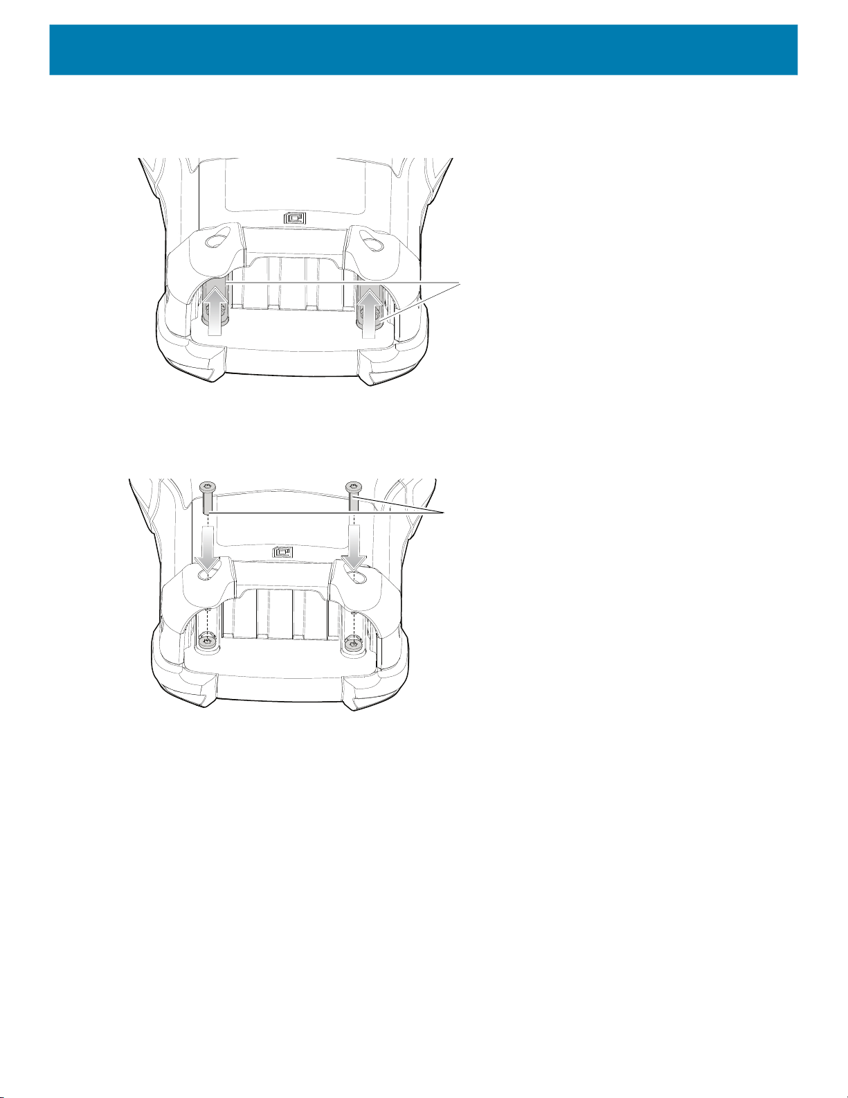
Removing and Replacing Keypads
1. Power off the device.
2. Remove the battery.
3. Using a Torx T8 screwdriver with a large grip, remove the two keypad latch screws from inside the battery
slot.
Figure 13 Remove Keypad Latch Screws
24
Keypad Latch Screws

Getting Started
4. Slide the keypad latches toward the bottom of the device.
Figure 14 Release Keypad Latches
Screwdriver
Keypad Latches
NOTE: If the keypad latches are hard to move, use a screwdriver to gently slide them towards the bottom of the device.
5. Turn the device over so that the keypad is visible.
6. Using a Torx T8 screwdriver with a large grip, remove the two keypad assembly screws from the top of the
keypad.
Figure 15 Remove Keypad
Keypad Screws
Keypad
microSD Card Holder
25

Getting Started
7. Lift the keypad from the device.
8. Align the keypad along the bottom ridge of the device, and then lay it flat.
Figure 16 Replace Keypad
9. Using a Torx T8 screwdriver with a large grip and a long shaft, secure the keypad to the device using the
two screws. Torque screws to 5.8 kgf-cm or 5.0 lbf-in.
Figure 17 Replace Keypad Screws
Keypad Screws
10.Turn the device over so that the keypad latches are visible.
26
Getting Started
11.Slide both the keypad latches toward the top of the device.
Figure 18 Slide Keypad Latches
Keypad Latches
12.Using a Torx T8 screwdriver, replace the two keypad latch screws inside the battery slot and torque to 5.8
kgf-cm or 5.0 lbf-in.
Figure 19 Replace Keypad Latch Screws
Keypad Latch Screws
13.Insert the battery.
14.Press and hold the Power key to power on the device.
27

Accessories
Introduction
This chapter provides information for using the accessories for the device.
MC93XX Accessories
The table below lists the accessories available for the device.
Table 4 MC93XX Accessories
Accessory Part Number Description
Cradles
1-Slot USB Charge Cradle with Spare
Battery Charger
4-Slot Charge Only ShareCradle CRD-MC93-4SCHG-01 Charges up to four MC93XXs. Requires power
CRD-MC93-2SUCHG-01 Charges the MC93XX main battery and a spare
battery, and synchronizes the MC93XX with a
host computer through a USB connection.
Requires power supply
(PWR-BGA12V50W0WW), DC line cord
(CBL-DC-388A1-01) and a country specific
grounded AC line cord.
supply (PWR-BGA12V108W0WW), DC line cord
(CBL-DC-381A1-01) and a country specific
grounded AC line cord.
4-Slot Ethernet ShareCradle CRD-MC93-4SETH-01 Charges up to four MC93XXs through the main
battery and synchronizes the devices with a host
computer through an Ethernet connection.
Requires power supply
(PWR-BGA12V108W0WW), DC line cord
(CBL-DC-381A1-01) and a country specific
grounded AC line cord.
Chargers
4-Slot Spare Battery Charger SAC-MC93-4SCHG-01 Charges up to four MC93XX spare batteries.
Requires power supply
(PWR-BGA12V50W0WW), DC line cord
(CBL-DC-388A1-01) and a country specific
grounded AC line cord.
28

Accessories
Table 4 MC93XX Accessories (Continued)
Accessory Part Number Description
16-Slot Spare Battery Charger SAC-MC93-16SCHG-01 Charges up to 16 MC93XX spare batteries.
Requires power supply
(PWR-BGA12V108W0WW), DC line cord
(CBL-DC-381A1-01) and a country specific
grounded AC line cord.
Power Supply PWR-BGA12V50W0WW Provides 12 VDC, 4.16A power to the 1-Slot
USB Charge Cradle and the 4-Slot Spare Battery
Charger. Requires a DC line cord
(CBL-DC-388A1-01) and a country specific
grounded AC line cord.
Power Supply PWR-BGA12V108W0WW Provides 12 VDC, 9A power to the 4-Slot Charge
Cradle with 4-Slot Battery Charger, and 16-Slot
Battery Charger. Requires a DC line cord
(CBL-DC-381A1-01) and a country specific
grounded AC line cord.
Power Supply PWR-WUA5V12W0US Provides 5 VDC, 2.5A power to the USB Charge
Cable. Includes plug adapter for use in the
United States.
Power Supply PWR-WUA5V12W0GB Provides 5 VDC, 2.5A power to the USB Charge
Cable. Includes plug adapter for use in the
European Union.
Power Supply PWR-WUA5V12W0EU Provides 5 VDC, 2.5A power to the USB Charge
Cable. Includes plug adapter for use in the
United Kingdom.
Power Supply PWR-WUA5V12W0AU Provides 5 VDC, 2.5A power to the USB Charge
Cable. Includes plug adapter for use in Australia.
Power Supply PWR-WUA5V12W0CN Provides 5 VDC, 2.5A power to the USB Charge
Cable. Includes plug adapter for use in China.
Power Supply PWR-WUA5V12W0IN Provides 5 VDC, 2.5A power to the USB Charge
Cable. Includes plug adapter for use in India.
US AC Line Cord 23844-00-00R Provides power to 3–wire power supplies
PWR-BGA12V50W0WW and
PWR-BGA12V108W0WW.
DC Line Cord CBL-DC-381A1-01 Provides power from the power supply
(PWR-BGA12V108W0WW) to the 4-Slot
Charge Only Cradle, 4-Slot Ethernet Cradle,
and 16-Slot Battery Charger.
DC Line Cord CBL-DC-388A1-01 Provides power from the power supply
(PWR-BGA12V150W0WW) to the 1-Slot USB
Charge Cradle and 4-Slot Battery Charger.
29

Accessories
Table 4 MC93XX Accessories (Continued)
Accessory Part Number Description
Cables
USB Charge/Com Snap-On Cup
NOTE: A separate USB cable and power
supply is required to support fast charging.
USB (Type-C) Cable is required to allow
communication from the snap-on to the
PC/laptop.
1-Slot Cradle USB Cable CBL-TC2X-USBC-01 Provides USB communication through the 1-Slot
Miscellaneous
Cradle Adapter ADP-MC93-CRDCUP-01 MC93XX Charge Only Adapter for backwards
7000mAh PowerPrecision+ standard
battery
CBL-MC93-USBCHG-01 Provides power and/or communication over USB
to the device. Requires wall adapter/power
supply PWR-WUA5V12W0xx.
USB cradle to the host computer.
compatibility with MC9XX cradles. Works with
MC9XX 1-Slot USB Cradle, and 4-Slot Charge
Only Cradle.
BTRY-MC93-STN-01
Replacement standard battery.
5000mAh PowerPrecision+ freezer
BTRY-MC93-STN-10
BTRY-MC93-STN-IN
BTRY-MC93-FRZ-01
Replacement standard battery (10–pack).
Replacement standard battery (India).
Replacement freezer battery.
battery
7000mAh PowerPrecision+
BTRY-MC93-FRZ-10
BTRY-MC93-NI-01
Replacement freezer battery (10–pack).
Replacement non-incendive battery.
non-incendive battery
BTRY-MC93-NI-10
Replacement non-incendive battery (10–pack).
MC93XX Hand Strap SG-MC93-HDSTPG-01 Replacement hand strap for the MC93XX Hand
strap loop holds an optional stylus
(SG-TC7X-STYLUS-03).
MC93 Soft Holster for Gun SG-MC9X-SHLSTG-01 Provides a soft, clip on holster and a shoulder
strap for the MC93XX.
MC93 Rubber Boot for Gun SG-MC93-RBTG-01 Provides additional protection for wear and tear
of the MC93XX.
Screen Protector MISC-MC93-SCRN-01 Provides additional protection for display
(5-pack).
Stylus and Tether SG-TC7X-STYLUS-03 Conductive carbon-filled stylus for capacitive
touch panel; includes coiled tether (3-pack).
Un-powered Forklift Mount MNT-MC93-FLCH-01 Un-powered forklift mount. Allows installing the
device on a roll bar or square surface of a forklift.
Includes:
Forklift holder (MNT-MC93-FLCH-01), RAM
double socket arm for 1” ball
(MNT-RAM-B201U), and RAM forklift clamp 2.5”
max width square rail base with 1” ball
(MNT-RAM-B247U25).
30

Accessories
Table 4 MC93XX Accessories (Continued)
Accessory Part Number Description
34-key Numeric Keypad KYPD-MC9334FNR-01 34-key Numeric Keypad
43-key Shifted Alpha Keypad KYPD-MC9343FN-01 43-key Shifted Alpha Keypad
53-key 3270 Emulator Keypad KYPD-MC93533270-01 53-key 3270 Emulator Keypad
53-key Keypad (Alpha-Numeric) KYPD-MC93535250-01 53-key Keypad (Alpha-Numeric)
53-key 5250 Emulator Keypad KYPD-MC9353ANR-01 53-key 5250 Emulator Keypad
53-key VT Emulator Keypad KYPD-MC9353VT-01 53-key VT Emulator Keypad
58-Keys OmniiXT15f Keypad KYPD-MC9358ANR-01 58-Keys OmniiXT15f Keypad
29-Keys Shifted Alpha Keypad KYPD-MC9329NMR-01 29-Keys Shifted Alpha Keypad
34-key Numeric Keypad (10 Pack) KYPD-MC9334FNR-10 34-key Numeric Keypad (10 Pack)
NOTE: The 10 pack order includes a keypad
installation tool.
43-key Shifted Alpha Keypad
(10 Pack)
53-key 5250 Emulator Keypad
(10 Pack)
53-key VT Emulator Keypad
(10 Pack)
53-key Keypad (Alpha-Numeric)
(10 Pack)
58-Keys OmniiXT15f Keypad KYPD-MC9358ANR-10 58-Keys OmniiXT15f Keypad (10 Pack)
KYPD-MC9343FN-10 43-key Shifted Alpha Keypad (10 Pack)
NOTE: The 10 pack order includes a keypad
installation tool.
KYPD-MC93535250-10 53-key 5250 Emulator Keypad (10 Pack)
NOTE: The 10 pack order includes a keypad
installation tool.
KYPD-MC9353VT-10 53-key VT Emulator Keypad (10 Pack)
NOTE: The 10 pack order includes a keypad
installation tool.
KYPD-MC9353ANR-10 53-key Keypad (Alpha-Numeric) (10 Pack)
NOTE: The 10 pack order includes a keypad
installation tool.
NOTE: The 10 pack order includes a keypad installa-
tion tool.
29-Keys Shifted Alpha Keypad KYPD-MC9329NMR-10 29-Keys Shifted Alpha Keypad (10 Pack)
NOTE: The 10 pack order includes a keypad installa-
tion tool.
31

Accessories
1-Slot USB Charge Cradle with Spare Battery Charger
The 1-Slot USB Charge Cradle with spare battery:
• Provides 9 VDC power to operate the mobile computer and charge the battery.
• Provides 4.2 VDC power to charge the spare battery.
• Provides a USB port for data communication between the mobile computer and a host computer or other
USB devices, for example, a printer.
• Synchronizes information between the mobile computer and a host computer. With customized or third
party software, it can also synchronize the mobile computer with corporate databases.
• Compatible with the following batteries:
• 7000mAh PowerPrecision+ standard battery
• 5000mAh PowerPrecision+ freezer battery
• 7000mAh PowerPrecision+ non-incendive battery.
Setup
Figure 20 1-Slot USB Charge Cradle with Spare Battery Charger Setup
USB Cable
Charging the Device
AC Line Cord
Power Supply
1. Connect the cradle to a power source.
32

Accessories
Figure 21 1-Slot USB Charge Cradle with Spare Battery Charger
Spare Battery
Spare Battery Charging Well
Spare Battery Charging LED
2. Slide the device into the slot in the cradle. The device Charge LED Indicator, indicates the battery charging
status.
3. Gently press down on the device to ensure proper contact.
4. When charging is complete, remove the devices from the cradle slot.
Indicator LED Bar
The 1-Slot USB charge cradle charges the MC93XX’s main battery and a spare battery simultaneously.
33

Accessories
The MC93XX’s Charge LED indicates the status of the battery charging in the device. See LED Charge
Indicators for charging status indications.
Table 5 LED Charge Indicators
Status Indications
Off • The battery is not charging.
• The device is not inserted correctly in the cradle or connected to a
power source.
• Cradle is not powered.
Slow Blinking Amber
Every 3 seconds
Solid Amber • Battery is charging.
Solid Green • Battery charging is complete.
Fast Blinking Red
2 blinks/second
Solid Red • Battery is charging and battery is at the end of useful life.
• Battery is charging, but the battery is fully depleted and does not yet
have sufficient charge to power the device.
Charging error. For example:
• Temperature is too low or too high.
• Charging has gone on too long without completion (typically eight
hours).
• Charging complete and battery is at the end of useful life.
The 7000mAh PowerPrecision+ standard battery charges from 0% to 90% in less than 3.5 hours at room
temperature using a Zebra accessory.
The 5000mAh PowerPrecision+ freezer battery charges from 0% to 90% in less than 2.5 hours at room
temperature using a Zebra accessory.
The 7000mAh PowerPrecision+ non-incendive battery charges from 0% to 90% in less than 3.5 hours at room
temperature using a Zebra accessory.
Charging Temperature
Charge batteries in temperatures from 0°C to 40°C (32°F to 104°F). The device or cradle always performs
battery charging in a safe and intelligent manner. At higher temperatures, for example at approximately +37°C
(+98°F), the device or cradle may for small periods of time alternately enable and disable battery charging to
keep the battery at acceptable temperatures. The device and cradle indicates when charging is disabled due to
abnormal temperatures via its LED.
34

4-Slot Charge Only ShareCradle
CAUTION: Ensure that you follow the guidelines for battery safety described in Battery Safety Guidelines.
The 4-Slot Charge Only ShareCradle:
• Provides 9 VDC power to operating the mobile computer and charge the battery.
• Simultaneously charges up to four mobile computers.
Setup
Figure 22 4-Slot Charge Only ShareCradle Setup
Accessories
AC Line Cord
Charging the Devices
Power Supply
DC Line Cord
1. Connect the cradle to a power source.
2. Slide the devices into the slot in the cradle. The devices Charge LED Indicator, indicates the battery
charging status.
35

Accessories
Figure 23 4-Slot Charge Only ShareCradle
Power LED
3. Gently press down on the device to ensure proper contact.
4. When charging is complete, remove the devices from the cradle slot.
Charging Temperature
Charge batteries in temperatures from 0°C to 40°C (32°F to 104°F). The device or cradle always performs
battery charging in a safe and intelligent manner. At higher temperatures, for example at approximately +37°C
(+98°F), the device or cradle may for small periods of time alternately enable and disable battery charging to
keep the battery at acceptable temperatures. The device and cradle indicates when charging is disabled due to
abnormal temperatures via its LED.
36
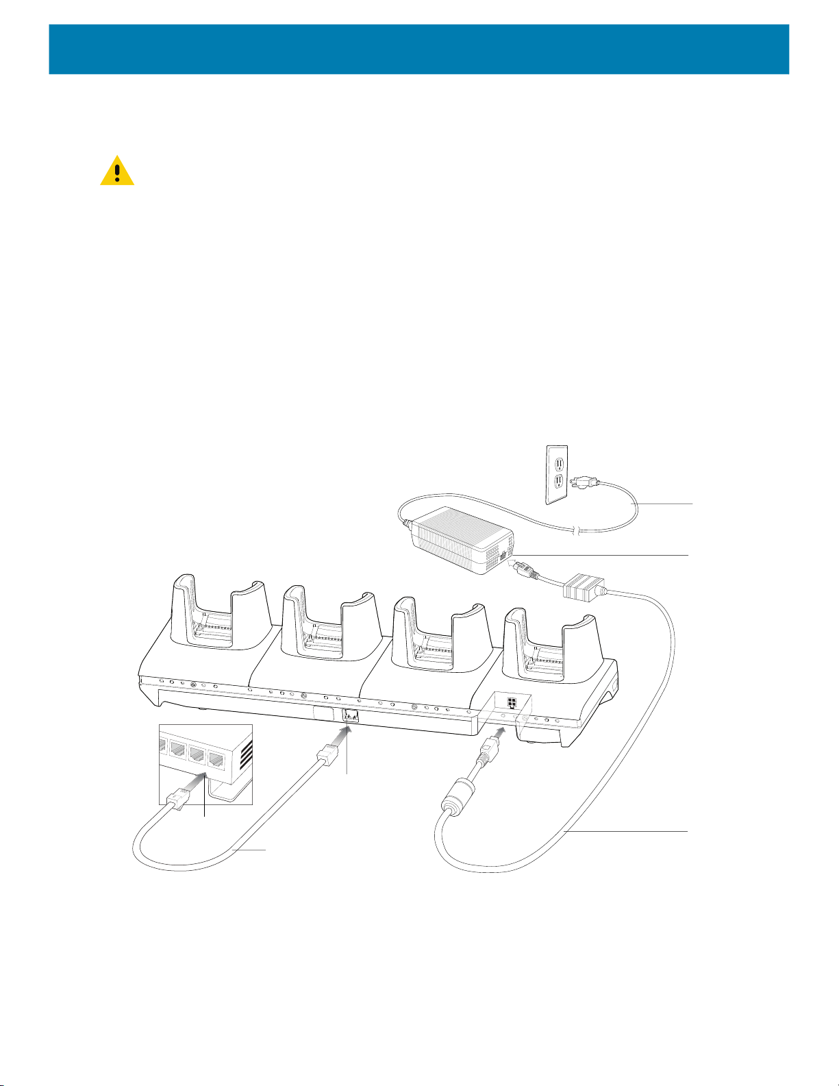
4-Slot Ethernet ShareCradle
CAUTION: Ensure that you follow the guidelines for battery safety described in Battery Safety Guidelines.
The 4-Slot Ethernet ShareCradle:
• Provides 9 VDC power to operating the mobile computer and charge the battery.
• Enables data communication between the MC93XX (up to four devices) and a host computer, over an
Ethernet network (using a standard Ethernet cable).
• Synchronizes information between the MC93XX and a host computer. (With customized or third-party
software, it can also be used to synchronize the MC93XX with corporate databases.)
• Simultaneously charges up to four devices.
Setup
Figure 24 4-Slot Ethernet ShareCradle Setup
Accessories
Router
AC Line Cord
Power Supply
Primary Port
DC Line Cord
Ethernet Cable
Charging the Devices
1. Connect the cradle to a power source.
2. Slide the devices into the slot in the cradle. The devices Charge LED Indicator, indicates the battery
charging status.
37

Figure 25 4-Slot Ethernet ShareCradle
Accessories
Power LED
3. Gently press down on the device to ensure proper contact.
4. When charging is complete, remove the devices from the cradle slot.
Daisy-chaining Ethernet ShareCradles
Daisy-chain up to ten 4-Slot Ethernet ShareCradles to connect several cradles to an Ethernet network. Use
either a straight or crossover cable. Daisy-chaining should not be attempted when the main Ethernet
connection to the first cradle is 10 Mbps as throughput issues will almost certainly result.
To daisy-chain 4-Slot Ethernet ShareCradles:
1. Connect power to each 4-Slot Ethernet ShareCradle.
2. Connect an Ethernet cable to one of the ports on the switch and the other end to the Primary Port of the first
cradle.
3. Connect an Ethernet cable to the Secondary port of the first cradle.
4. Connect the other end of the Ethernet cable to the Primary port of the next 4-Slot Ethernet ShareCradle.
38

Accessories
Figure 26 Daisy-chaining 4-Slot Ethernet ShareCradles
To Switch
Primary Port
Secondary Port
To Power Supply
To Next Cradle
5. Connect additional cradles as described in step 3 and 4.
To Power Supply
Ethernet Settings
The following settings can be configured when using Ethernet communication:
• Proxy Settings
• Static IP.
Configuring Ethernet Proxy Settings
The MC93XX includes Ethernet cradle drivers. After inserting the device, configure the Ethernet connection:
1. Swipe down from the status bar to open the quick access panel and then touch .
2. Touch Network & Internet > Ethernet.
3. Slide the switch to the ON position.
4. Place the device into the Ethernet cradle slot.
5. Touch and hold eth0 until the menu appears.
6. Touch Modify Proxy.
7. Touch the Proxy drop-down list and select Manual.
39

Figure 27 Ethernet Proxy Settings
Accessories
8. In the Proxy hostname field, enter the proxy server address.
9. In the Proxy port field, enter the proxy server port number.
NOTE: When entering proxy addresses in the Bypass proxy for field, do not use spaces or carriage returns between ad-
dresses.
10.In the Bypass proxy for text box, enter addresses for web sites that do not require to go through the proxy
server. Use the separator comma “,” between addresses.
11.Touch MODIFY.
12.Touch .
Configuring Ethernet Static IP Address
The MC93XX includes Ethernet cradle drivers. After inserting the device, configure the Ethernet connection:
1. Swipe down from the status bar to open the quick access panel and then touch .
2. Touch Network & Internet > Ethernet.
3. Slide the switch to the ON position.
4. Place the device into the Ethernet cradle slot.
5. Touch eth0.
6. Touch Disconnect.
7. Touch eth0.
8. Touch the IP settings drop-down list and select Static.
40

Figure 28 Static IP Settings
Accessories
9. In the IP address field, enter the proxy server address.
10.If required, in the Gateway field, enter a gateway address for the device.
11.If required, in the Netmask field, enter the network mask address
12.If required, in the DNS address fields, enter a Domain Name System (DNS) addresses.
13.Touch CONNECT.
14.Touch .
Establishing Ethernet Connection
1. Swipe down from the status bar to open the quick access panel and then touch .
2. Touch Network & Internet > Ethernet.
3. Slide the Ethernet switch to the ON position.
4. Insert the device into a slot.
5. The icon appears in the Status bar.
6. Touch eth0 to view Ethernet connection details.
41

LED Indicators
There are two green LEDs on the side of the cradle. These green LEDs light and blink to indicate the data
transfer rate.
Table 6 LED Data Rate Indicators
Data Rate 1000 LED 100/10 LED
1 Gbps On/Blink Off
100 Mbps Off On/Blink
10 Mbps Off On/Blink
Charging Temperature
Charge batteries in temperatures from 0°C to 40°C (32°F to 104°F). The device or cradle always performs
battery charging in a safe and intelligent manner. At higher temperatures, for example at approximately +37°C
(+98°F), the device or cradle may for small periods of time alternately enable and disable battery charging to
keep the battery at acceptable temperatures. The device and cradle indicates when charging is disabled due to
abnormal temperatures via its LED.
Accessories
42
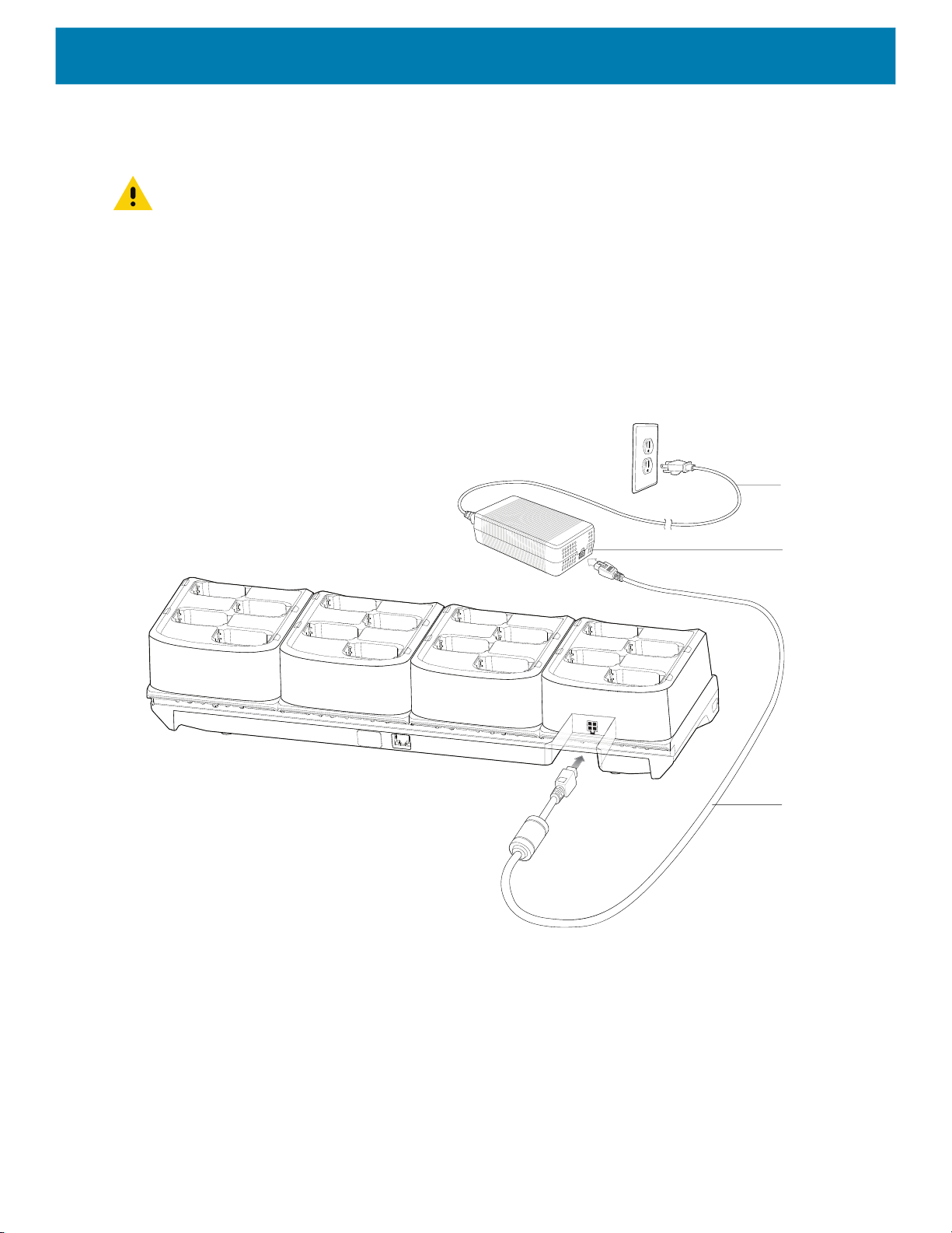
16-Slot Spare Battery Charger
CAUTION: Ensure that you follow the guidelines for battery safety described in Battery Safety Guidelines.
The 16-Slot Spare Battery Charger:
• Charges up to 16 spare batteries.
• Provides 4.2 VDC power to charge the spare battery.
Setup
Figure 29 16-Slot Spare Battery Charger Setup
Accessories
AC Line Cord
Charging the Spare Batteries
Power Supply
DC Line Cord
1. Connect the charger to a power source.
43

Figure 30 16-Slot Spare Battery Charger
Power LED
Accessories
Spare Battery Charging LED
2. Insert the battery into a spare battery charging slot and gently press down on the battery to ensure proper
contact.
The Spare Battery Charging LEDs on the front of the cradle indicates the spare battery charging status. The
following table specifies charging indicators.
Table 7 Spare Battery Charging LED Indicators
State Indication
Off • The battery is not charging.
• The battery is not inserted correctly in the cradle.
• Cradle is not powered.
Solid Amber • Battery is charging.
Solid Green • Battery charging is complete.
Fast Blinking Red
2 blinks/second
Solid Red • Battery is charging and battery is at the end of useful life.
Charging error. For example:
• Temperature is too low or too high.
• Charging has gone on too long without completion (typically eight
hours).
• Charging complete and battery is at the end of useful life.
Charging Temperature
Charge batteries in temperatures from 0°C to 40°C (32°F to 104°F). The device or cradle always performs
battery charging in a safe and intelligent manner. At higher temperatures, for example at approximately +37°C
(+98°F), the device or cradle may for small periods of time alternately enable and disable battery charging to
keep the battery at acceptable temperatures. The device and cradle indicates when charging is disabled due to
abnormal temperatures via its LED.
44

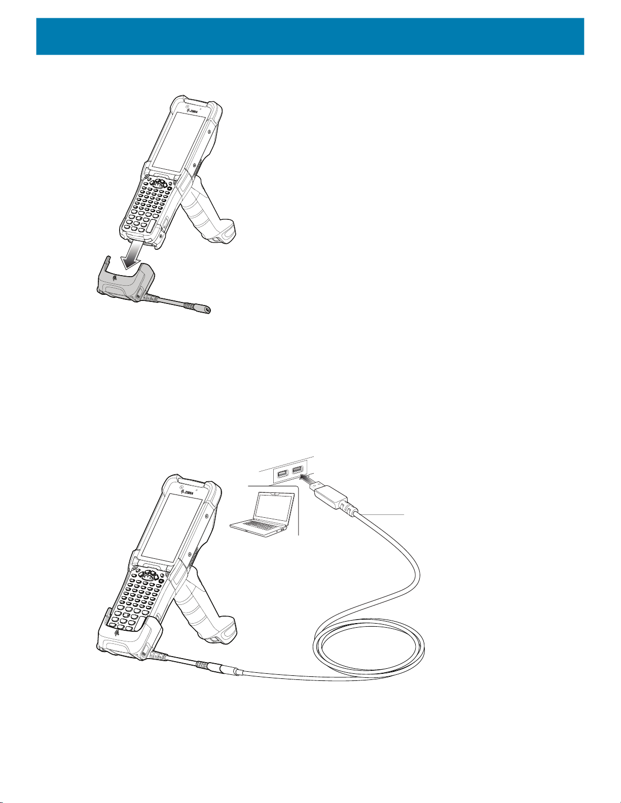
USB Charge/Com Snap-on Cup
The USB Charge/Com Snap-on Cup:
• Provides 5 VDC power to operate the device and to charge the battery.
• Provides power and/or communication with the host computer over USB to the device.
Figure 31 USB Charge/Com Snap-on Cup
Accessories
USB Charge/Com Snap-on Cup
Connecting to the Device
NOTE: To function properly, remove the lower part of the rubber boot or the entire rubber boot before placing the
device in a charging cradle.
Insert the device straight onto the USB Charge/Com Snap-on Cup until the device touches the bottom of the
cable cup.
Pigtail with USB Socket
45
Accessories
Figure 32 Connecting the USB Charge/Com Snap-on Cup
Connecting the USB Charge/Com Snap-on Cup Cable to Host Computer
To connect the USB Charge/Com Snap-on Cup cable to a host computer:
1. Connect the USB Charge/Com Snap-on Cup to the device.
2. Connect the USB connector to a host computer.
Figure 33 Connecting USB Charge/Com Snap-on Cup to Host Computer
USB Cable
46
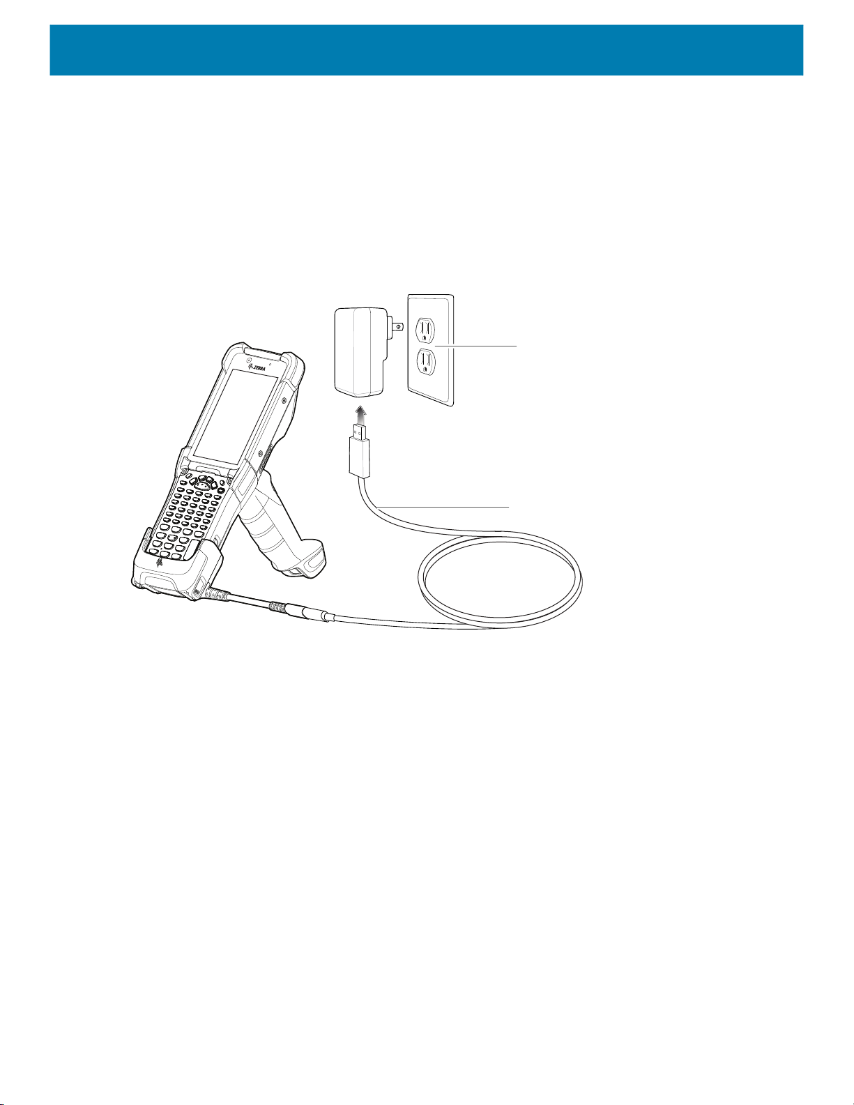
Charging the Device
To charge the device using the USB Charge/Com Snap-on Cup:
1. Connect the USB Charge/Com Snap-on Cup to the device.
2. Connect the USB connector of the power supply.
3. Plug the power supply into a power outlet.
Figure 34 Charging the Device using the USB Charge Cable
Accessories
Power Supply
USB Cable
Refer to the Charging the Main Battery section for information on charging indicator statuses.
Disconnecting the USB Charge/Com Snap-on Cup
To disconnect the USB Charge/Com Snap-on Cup from the device:
1. Depress the two latches on either side of the cup.
2. Pull the cup off the bottom of the device.
47

Accessories
Figure 35 Disconnecting the USB Charge/Com Snap-on Cup
MC93XX Charge Only Adapter
Use the Charge Only Adapter for backwards compatibility with the MC9XXX cradles and the MC93XX mobile
computer.
• Charge Only Adapter supports terminal charging only for the MC9XXX 1-Slot Cradle and 4-Slot Cradle.
• Charge Only Adapter provides charge only and no communication when used with the MC9XXX cradles.
48
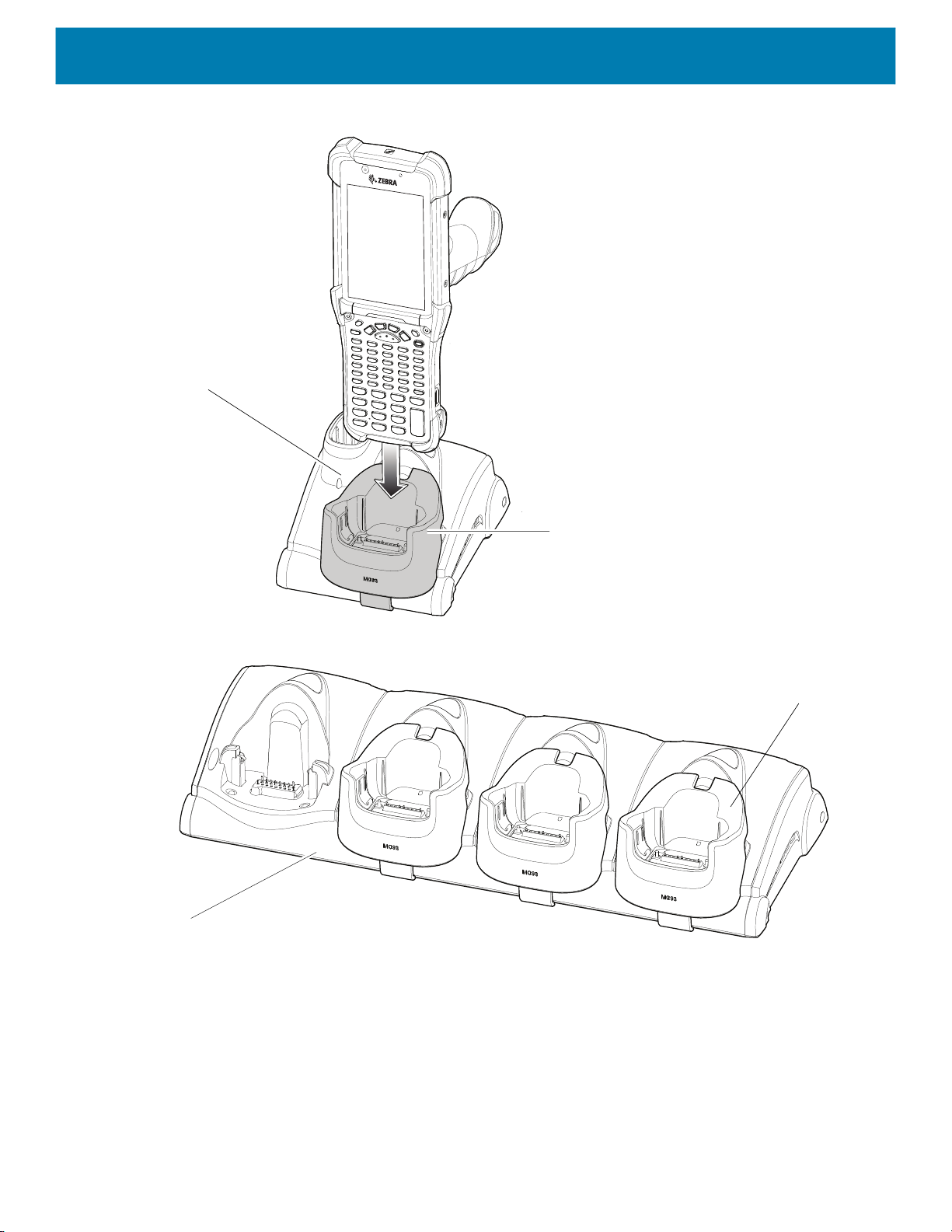
Accessories
Figure 36 MC9X 1-Slot Cradle Charge Only Adapter
Charge Only Adapter
Figure 37 MC9X 4-Slot Cradle Charge Only Adapter
MC92 4-Slot Cradle
MC92 1-Slot Cradle
Charge Only Adapter
Charge Only Adapter Installation
To install the Charge Only Adapter:
1. Clean the MC9XXX cradle and contacts surface as specified with an alcohol wipe, using a back and forth
motion with your finger.
For more information about cleaning, refer to the MC93XX Mobile Computer User Guide.
49

Accessories
Figure 38 Clean MC9XXX Cradle Contacts and Surfaces
Clean Cradle Contacts and Surface
2. Peel and remove the adhesive from the back of the adapter.
Figure 39 Peel and Remove Adhesive
Peel and Remove Adhesive Liner
3. Insert the adapter into the MC9XXX cradle and adhere to the bottom of the cradle.
50

Figure 40 Insert Adapter into Cradle
Accessories
4. Insert the device into the cradle.
Figure 41 Insert Device into Cradle
51

Rubber Boot
To attach the rubber boot:
1. If using the rubber boot with a device with the SE965 laser scanner, retain the shim (default assembly). If
using the rubber boot with a device with either the SE4750SR or the SE4850ER imager, you must snap-off
the shim by pushing it through.
Figure 42 Remove the Shim
2. Slide the top of the device into the top of the rubber boot.
Accessories
Shim
Figure 43 Slide the Rubber Boot
3. Grasp the bottom of the rubber boot and place over the bottom of the device.
Figure 44 Attach the Top of the Rubber Boot
4. Turn the device over and ensure that the two alignment tabs completely fit into the two alignment slots on
the device.
52

Accessories
Figure 45 Align tabs
Tabs
NOTE: To charge the device in a cradle, completely remove the rubber boot.
53

Installing the Hand Strap
To install the hand strap:
Accessories
1. Thread and
Figure 46 Insert Loop Through Handle Slot
2. Thread and
Figure 47 Pull-through Hand Strap Near Battery
pull-through the short sect i on t hr ough the opening near the base of the trigger handle.
pull-through the longer sect i on t hr ough the opening near the battery.
3. Attach the two plastic ends together.
Figure 48 Attach Plastic Ends Together
54

Accessories
4-Slot Charge Only ShareCradle Rack Installation
Use the Rack/Wall Mount Bracket to mount a 4-slot charge only sharecradle on a rack. When installing on a
rack, first assemble the bracket and cradles/chargers and then install the assembly on the rack.
1. Place the power supply in bottom tray.
2. Connect AC line cord to power supply.
3. Connect DC line cord to power supply.
4. Secure power supply and cables to bottom tray with tie wraps.
NOTE: Ensure tie wrap buckle is on side of power supply. Tie wrap buckle on top of power supply interferes with top tray.
5. Route cables through cable slots.
Figure 49 Power Supply in Bottom Tray
DC line Cord AC line CordPower Supply
6. Secure four M2.5 studs to top tray as shown.
Figure 50 Install Studs
7. Align and install 4-Slot cradle onto studs of top tray.
Studs (4)
55

Accessories
MC93
MC93
MC93
MC93
Figure 51 Align Cradle on Studs
8. Secure cradle to top tray with two M2.5 safety screws.
Figure 52 Secure Cradle
Safety Screws(2)
9. Slide top tray onto bottom tray.
56

Accessories
Figure 53 Slide Top Tray onto Bottom Tray
10.Connect cables to cradle.
Figure 54 Connect Cables
11.Secure top tray to bottom tray with 4 M5 screws (two on each side).
57

Accessories
Figure 55 Secure Top and Bottom Tray
See Rack Mount Installation on page 59 for installing the bracket assembly onto a rack.
58

Rack Mount Installation
NOTE: Use screws provided with rack system. Refer to rack user documentation for instructions.
1. Secure mounting brackets to both sides of top tray with four M5 screws (two on each side). For 4-Slot
cradles, position the flange for horizontal installation. For 4-Slot Battery Chargers, position the flange for
25° installation.
Figure 56 Flange Horizontal Position (4-Slot Cradles)
Accessories
Flange
Fifth Screw Hole
Figure 57 Flange 25° Position (4-Slot Battery Chargers)
Top Screw Hole
Flange
CAUTION: Install mounting bracket with 4-Slot cradle at a maximum height of four feet from ground.
Install mounting bracket with 4-Slot Battery Charger at a maximum height of three feet from ground.
NOTE: Distance between two horizontal mounted brackets should be at least 14” apart (from top of one flange to the top of
the next flange).
Distance between a horizontal mounted bracket and a 25° mounted bracket should be at least 16.25” apart (from top of one
flange to the top of the next flange).
There should be enough clearance (2.75”) between the top of the device and the bottom of the mounting bracket above.
2. Install two rack system screws for top of mounting brackets. The screw heads should protrude half way
from the rail.
59

Figure 58 Install Rack System Screws
14 “
MC93
MC93
MC93
MC93
MC93
MC93
MC93
MC93
Accessories
Rack Screws
3. Align the mounting bracket’s top mounting key holes with the screws.
4. Place the brackets on the screws.
Figure 59 Secure Bracket to Rack (Horizontal Position Shown)
60

Accessories
5. Secure the top screws.
6. Install bottom screws and tighten screws.
7. Route cables and connect to power source.
CAUTION: Installer should ensure that all building codes are followed when connecting the power supplies to an AC power
source.
While installing the brackets, power supplies and cables:
• Use tie wraps to secure cables to the bracket and rails.
• Coil cables wherever possible.
• Route power cables along the rails.
• Route inter-cradle cables to the side rails and then from the rails to the bracket.
61

Wall Installation
Use the Rack/Wall Mount Bracket to mount four 4-Slot Battery Chargers or a cradle on a wall. When installing
on a wall, first assemble the bottom tray, install the bottom tray on the wall and then assemble the top tray.
Use mounting hardware (screws and/or anchors) appropriate for the type of wall mounting the bracket onto.
The Mount Bracket mounting slots dimensions are 5 mm (0.2 in.). Fasteners must be able to hold a minimum
of 20 Kg (44 lbs.)
For proper installation consult a professional installer. Failure to install the bracket properly can possibly result
in damage to the hardware.
CAUTION: Install mounting bracket with 4-Slot cradle at a maximum height of four feet from ground.
Install mounting bracket with 4-Slot Battery Charger at a maximum height of three feet from ground.
Bottom Tray Assembly
See steps 1 through 5 in 4-Slot Charge Only ShareCradle Rack Installation on page 55 for instructions.
Bracket Wall Mounting
Accessories
1. Drill holes and install anchors according to the template supplied with the bracket.
2. Install two screws for bottom of bracket. The screw heads should protrude 2.5 mm (0.01”) from the wall.
Figure 60 Horizontal Mounting Template
398 mm
22.85 mm
3. Align the mounting bracket’s bottom mounting key holes with the screws.
4. Hang the bracket on the screws.
62
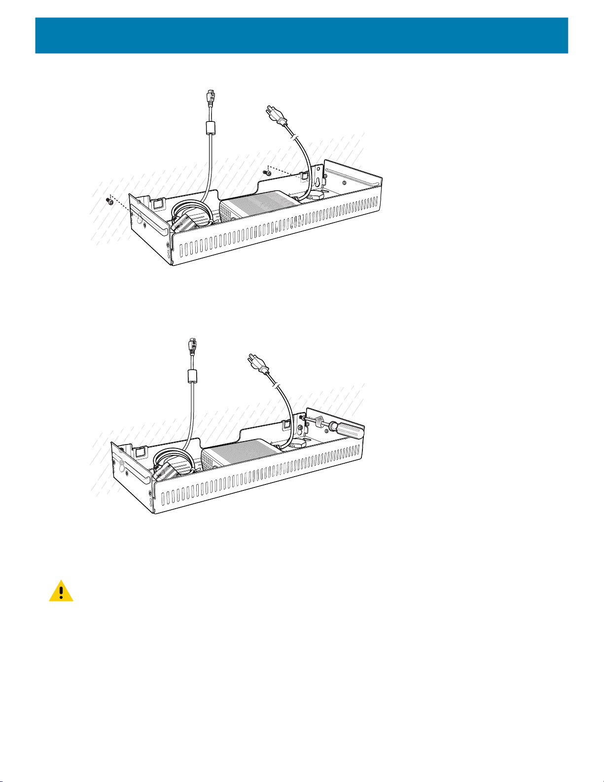
Figure 61 Horizontal Installation
5. Install two top screws.
6. Tighten all screws.
Accessories
Figure 62 Horizontal Installation - Tighten Screws
7. Assemble the four 4-Slot Battery Chargers or cradle onto the bracket. See steps 7 through 11 in 4-Slot
Charge Only ShareCradle Rack Installation on page 55.
8. Route cables and connect to power source.
CAUTION: Installer should ensure that all building codes are followed when connecting the power supplies to an AC power
source.
While installing the brackets, power supplies and cables:
• Use tie wraps to secure cables to the bracket and rails.
• Coil cables wherever possible.
• Route power cables along the rails.
• Route inter-cradle cables to the side rails and then from the rails to the bracket.
63

Settings
Introduction
This chapter describes settings available for configuring the device.
WLAN Configuration
This section provides information on configuring Wi-Fi settings.
Configuring a Secure Wi-Fi Network
To set up a Wi-Fi network:
1. Swipe down from the Status bar to open the Quick Access panel, and then touch .
2. Touch Network & Internet > Wi-Fi.
3. Slide the switch to the ON position.
4. The device searches for WLANs in the area and lists them on the screen.
5. Scroll through the list and select the desired WLAN network.
6. Touch the desired network. If the network security is Open, the device automatically connects to
the network. For all other network security a dialog box appears.
Figure 63 WLAN WEP Network Security Dialog Box
64
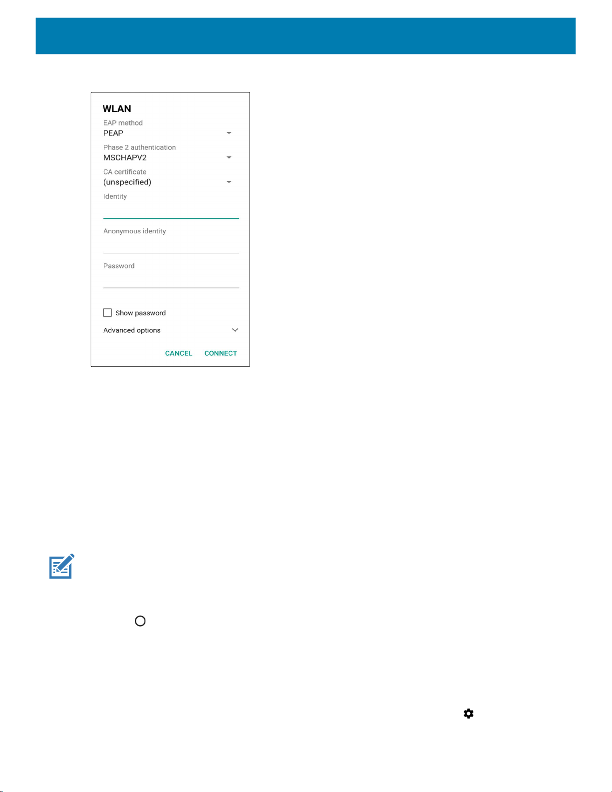
Settings
Figure 64 WLAN 802.11 EAP Network Security Dialog Box
7. If the network security is WEP or WPA/WPS2 PSK, enter the required password and then touch Connect.
8. If the network security is 802.1x EAP:
• Touch the EAP method drop-down list and select PEAP, TLS, TTLS, or LEAP.
• Touch the Phase 2 authentication drop-down list and select an authentication method.
• If required, touch CA certificate and select a Certification Authority (CA) certificate. Note: Certificates
are installed using the Security settings.
• If required, touch User certificate and select a user certificate. Note: User certificates are installed
using the Location & security settings.
• If required, in the Identity text box, enter the username credentials.
• If desired, in the Anonymous identity text box, enter an anonymous identity username.
• If required, in the Password text box, enter the password for then given identity.
NOTE: By default, the network Proxy is set to None and the IP settings is set to DHCP. See Configuring for a Proxy Server
for setting connection to a proxy server and see Configuring the Device to Use a Static IP Address for setting the device to
use a static IP address.
9. Touch Connect.
10.Touch .
Manually Adding a Wi-Fi Network
Manually add a Wi-Fi network if the network does not broadcast its name (SSID) or add a Wi-Fi network when
out of range.
1. Swipe down from the Status bar to open the Quick Access panel, and then touch .
65

Settings
2. Touch Network & Internet > Wi-Fi.
3. Slide the Wi-Fi switch to the On position.
4. Scroll to the bottom of the list and select Add network.
5. In the Network name text box, enter the name of the Wi-Fi network.
6. In the Security drop-down list, set the type of security to:
• None
• WEP
• WPA/WPA2 PSK
• 802.1x EAP.
7. If the network security is None, touch Save.
8. If the network security is WEP or WPA/WPA2 PSK, enter the required password, and then touch Save.
9. If the network security is 802.1x EAP:
• Touch the EAP method drop-down list and select PEAP, TLS, TTLS, or LEAP.
• Touch the Phase 2 authentication drop-down list and select an authentication method.
• If required, touch CA certificate and select a Certification Authority (CA) certificate. Note: Certificates
are installed using the Security settings.
• If required, touch User certificate and select a user certificate. Note: User certificates are installed
using the Security settings.
• If required, in the Identity text box, enter the username credentials.
• If desired, in the Anonymous identity text box, enter an anonymous identity username.
• If required, in the Password text box, enter the password for the given identity.
NOTE: By default, the network Proxy is set to None and the IP settings is set to DHCP. See Configuring for a Proxy Server
for setting connection to a proxy server and see Configuring the Device to Use a Static IP Address for setting the device to
use a static IP address.
10.Touch Save. To connect to the saved network, touch and hold on the saved network and select Connect to
network.
11.Touch .
Configuring for a Proxy Server
A proxy server is a server that acts as an intermediary for requests from clients seeking resources from other
servers. A client connects to the proxy server and requests some service, such as a file, connection, web
page, or other resource, available from a different server. The proxy server evaluates the request according to
its filtering rules. For example, it may filter traffic by IP address or protocol. If the request is validated by the
filter, the proxy provides the resource by connecting to the relevant server and requesting the service on behalf
of the client.
It is important for enterprise customers to be able to set up secure computing environments within their
companies, making proxy configuration essential. Proxy configuration acts as a security barrier ensuring that
the proxy server monitors all traffic between the Internet and the intranet. This is normally an integral part of
security enforcement in corporate firewalls within intranets.
To configure the device for a proxy server:
66

Settings
1. Swipe down from the Status bar to open the Quick Access panel, and then touch .
2. Touch Network & Internet > Wi-Fi.
3. Slide the Wi-Fi switch to the On position.
4. In the network dialog box, select and touch a network.
5. Touch Advanced options.
6. Touch Proxy and select Manual.
Figure 65 Proxy Settings
7. In the Proxy hostname text box, enter the address of the proxy server.
8. In the Proxy port text box, enter the port number for the proxy server.
9. In the Bypass proxy for text box, enter addresses for web sites that are not required to go through the
proxy server. Use a comma “,” between addresses. Do not use spaces or carriage returns between
addresses.
10.Touch Connect.
11.Touch .
Configuring the Device to Use a Static IP Address
By default, the device is configured to use Dynamic Host Configuration Protocol (DHCP) to assign an Internet
protocol (IP) address when connecting to a wireless network.
To configure the device to connect to a network using a static IP address:
1. Swipe down from the Status bar to open the Quick Access panel, and then touch .
2. Touch Network & Internet > Wi-Fi.
67

Settings
3. Slide the Wi-Fi switch to the On position.
4. In the network dialog box, select and touch a network.
5. Touch Advanced options.
6. Touch IP settings and select Static.
Figure 66 Static IP Settings
7. In the IP address text box, enter an IP address for the device.
8. If required, in the Gateway text box, enter a gateway address for the device.
9. If required, in the Network prefix length text box, enter the prefix length.
10.If required, in the DNS 1 text box, enter a Domain Name System (DNS) address.
11.If required, in the DNS 2 text box, enter a DNS address.
12.Touch Connect.
13.Touch .
Wi-Fi Preferences
Use the Wi-Fi preferences to configure advanced Wi-Fi settings. From the Wi-Fi screen scroll down to the
bottom of the screen and touch Wi-Fi preferences.
• Open network notification - When enabled, notifies the user when an open network is available.
• Advanced - Touch to expand options.
• Additional settings - See Additional Settings.
• Install Certificates – Touch to install certificates.
• Network rating provider - Disabled (AOSP devices). To help determine what constitutes a good Wi-Fi
network, Android supports external Network rating providers that provide information about the quality of
68

open Wi-Fi networks. Select one of the providers listed or None. If none are available or selected, the
Connect to open networks feature is disabled.
• MAC address - Displays the Media Access Control (MAC) address of the device when connecting to
Wi-Fi networks.
• IP address - Displays the IP address of the device when connecting to Wi-Fi networks.
Additional Wi-Fi Settings
NOTE: Additional Wi-Fi settings are for the device, not for a specific wireless network.
Use the Additional Settings to configure additional Wi-Fi settings. To view the additional Wi-Fi settings, scroll
to the bottom of the Wi-Fi screen and touch Wi-Fi Preferences > Advanced > Additional settings.
• Regulatory
• Country Selection - Displays the acquired country code if 802.11d is enabled, else it displays the
currently selected country code.
• Region code - Displays the current region code.
• Band and Channel Selection
• Wi-Fi frequency band - Set the frequency band to: Auto (default), 5 GHz only or 2.4 GHz only.
• Available channels (2.4 GHz) - Touch to display the Available channels menu. Select specific
channels and touch OK.
• Available channels (5 GHz) - Touch to display the Available channels menu. Select specific channels
and touch OK.
• Logging
• Advanced Logging – Touch to enable advanced logging or change the log directory.
• Wireless logs - Use to capture Wi-Fi log files.
• Fusion Logger - Touch to open the Fusion Logger application. This application maintains a history
of high level WLAN events which helps to understand the status of connectivity.
• Fusion Status - Touch to display live status of WLAN state. Also provides information about the
device and connected profile.
• About
• Version - Displays the current Fusion information.
Settings
Wi-Fi Direct
Wi-Fi Direct devices can connect to each other without having to go through an access point. Wi-Fi Direct
devices establish their own ad-hoc network when required, letting you see which devices are available and
choose which one you want to connect to.
1. Swipe down from the status bar and then touch .
2. Touch Wi-Fi > Wi-Fi preferences > Advanced > Wi-Fi Direct. The device begins searching for another
Wi-Fi Direct device.
69

Figure 67 Wi-Fi Direct Screen
Settings
3. Under Peer devices, touch the other device name.
4. On the other device, select Accept.
5. Connected appears on the device. On both devices, in their respective Wi-Fi Direct screens, the other
device name appears in the list.
WPS Push Button
Wi-Fi Protected Setup (WPS) is a feature allowing devices to easily connect to Wi-Fi access points without
typing a long password.
To use a wireless router WPS button:
1. On the device, swipe down from the status bar and then touch .
2. Touch Wi-Fi > Wi-Fi preferences > Advanced > WPS Push Button. A dialog box displays.
Figure 68 WPS Setup Dialog Box
3. On the wireless router, locate the WPS button. The device connects to the wireless router.
70

WPS Pin Entry
Wi-Fi Protected Setup (WPS) is a feature allowing devices to easily connect to Wi-Fi access points without
typing a long password.
To use a PIN to connect to a wireless router:
1. Log in to the router.
2. Go to the Add WPS Client screen. Refer to the wireless router user documentation specific information.
3. On the device, swipe down from the status bar, and then touch .
4. Touch Wi-Fi > Wi-Fi preferences > Advanced > WPS Pin Entry. A dialog box displays with an Pin
number.
Figure 69 Pin Entry Dialog Box
Settings
5. On the router, enter the Pin number. The device connects to the wireless router.
Setting Screen Lock
Use the Device security settings to set preferences for locking the screen.
1. Swipe down from the Status bar to open the Quick Access panel, and then touch .
2. Touch Security & location.
NOTE: Options vary depending upon the policy of some apps, such as email.
• Screen lock - Touch to configure the device to require a slide, pattern, PIN, or password to unlock the
screen.
• None - Disable screen unlock security.
• Swipe - Slide the lock icon to unlock the screen.
• Pattern - Draw a pattern to unlock screen. See Setting Screen Unlock Using Pattern for more
information.
• PIN - Enter a numeric PIN to unlock screen. See Setting Screen Lock Using PIN for more information.
• Password - Enter a password to unlock screen. See Setting Screen Unlock Using Password for more
information.
Lock the screen to protect access to data on the device. Some email accounts require locking the screen. The
Locking feature functions differently in Single-user versus Multiple-user mode.
When locked, a slide, pattern, PIN or password is required to unlock the device. Press the Power button to lock
the screen. The device also locks after a pre-defined time-out.
71

Press and release the Power button to wake the device. The Lock screen displays.
Slide the screen up to unlock. If the Pattern screen unlock feature is enabled, the Pattern screen appears
instead of the Lock screen.
If the PIN or Password screen unlock feature is enabled, enter the PIN or password after unlocking the screen.
Setting Screen Lock Using PIN
1. Swipe down from the Status bar to open the Quick Access panel, and then touch .
2. Touch Security & location.
3. Touch Screen lock.
4. Touch PIN.
5. To require a PIN upon device start up select Yes, or select No not to require a PIN.
Figure 70 PIN Screen
Settings
6. Touch in the text field.
7. Enter a PIN (4 numbers), and then touch Next.
8. Re-enter PIN and then touch Next.
9. Select the type of notifications that appear when the screen is locked and then touch Done.
10.Touch . The next time the device goes into suspend mode a PIN is required upon waking.
Setting Screen Unlock Using Password
1. Swipe down from the Status bar to open the Quick Access panel, and then touch .
72

Settings
2. Touch Security & location.
3. Touch Screen lock.
4. Touch Password.
5. To require a password upon device start up select Yes, or select No not to require a password.
6. Touch in the text field.
7. Enter a password (between 4 and 16 characters), and then touch Next.
Figure 71 Password Screen
8. Re-enter the password and then touch Next.
9. Select the type of notifications that appear when the screen is locked and then touch Done.
10.Touch . The next time the device goes into suspend mode a password is required upon waking.
Setting Screen Unlock Using Pattern
1. Swipe down from the Status bar to open the Quick Access panel, and then touch .
2. Touch Security & location.
3. Touch Screen lock.
4. Touch Pattern.
5. To require a pattern upon device start up select Yes, or select No not to require a pattern.
73
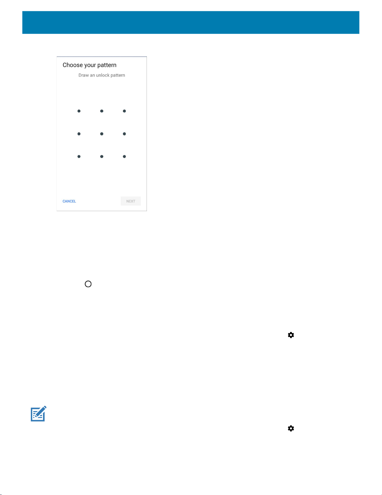
Figure 72 Choose Your Pattern Screen
Settings
6. Draw a pattern connecting at least four dots.
7. Touch Continue.
8. Re-draw the pattern.
9. Touch Confirm.
10.Select the type of notifications that appear when the screen is locked, and then touch Done.
11.Touch . The next time the device goes into suspend mode a pattern is required upon waking.
Showing Passwords
To set the device to briefly show password characters as the user types:
1. Swipe down from the Status bar to open the Quick Access panel and then touch .
2. Touch Security & location.
3. Slide the Show passwords switch to the ON position.
Remapping a Button
Buttons on the device can be programmed to perform different functions or as shortcuts to installed apps.
NOTE: It is not recommended to remap the scan button.
1. Swipe down from the Status bar to open the Quick Access panel and then touch .
2. Touch Key Programmer. A list of programmable buttons displays.
74

Figure 73 Button Remap Program Screen
3. Select the button to remap.
Figure 74 KeyProgrammer Screen
Settings
4. Touch the BUTTON REMAPPING tab or the SHORTCUT tab that lists the available functions and
5. Touch a function or application shortcut to map to the button.
NOTE: If you select an application shortcut, the application icon appears next to the button on the Key Programmer screen.
6. Touch .
Accounts
Use the Accounts settings to add, remove, and manage accounts. Use these settings to control how
applications send, receive, and sync data on their own schedules, and whether applications can synchronize
user data automatically.
Applications may also have their own settings to control how they synchronize data; see the documentation for
those applications for details.
applications.
75

Language Usage
Use the Language & input settings to change the device’s language, including words added to the dictionary.
Changing the Language Setting
1. Swipe down from the Status bar to open the Quick Access panel and then touch .
2. Touch System > Languages & input.
3. Touch Languages. A list of available languages displays.
4. If the desired language is not listed, touch Add a language and select a language from the list.
5. Touch and hold to the right of the desired language, then drag it to the top of the list.
6. The operating system text changes to the selected language.
Adding Words to the Dictionary
Settings
1. Swipe down from the Status bar to open the Quick Access panel and then touch .
2. Touch System > Languages & input > Advanced > Personal dictionary.
3. If prompted, select the language where this word or phase is stored.
4. Touch + to add a new word or phrase to the dictionary.
5. Enter the word or phrase.
6. In the Shortcut text box, enter a shortcut for the word or phrase.
7. Touch .
Keyboard Settings
Use the Languages & input settings to configure the on-screen keyboards. The device contains the following
keyboard settings:
• Enterprise Keyboard
• Gboard - GMS devices only.
• Physical keyboard
PTT Express Configuration
Refer to the PTT Express User Guide at www.zebra.com/support for information on configuring the PTT
Express Client application.
RxLogger
RxLogger is a comprehensive diagnostic tool that provides application and system metrics, allows for the
creation of custom plug-ins, and diagnoses device and application issues. RxLogger logs the following
information: CPU load, memory load, memory snapshots, battery consumption, power states, wireless logging,
76
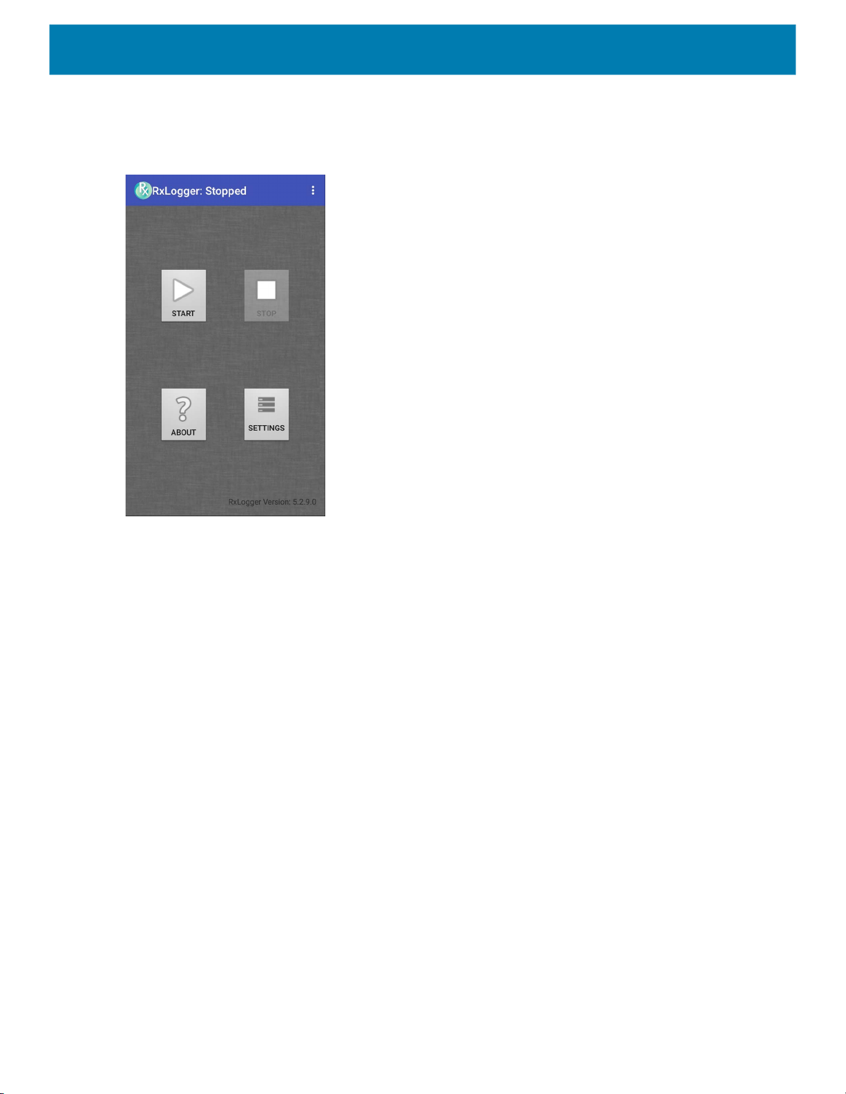
Settings
cellular logging, TCP dumps, Bluetooth logging, GPS logging, logcat, FTP push/pull, ANR dumps, etc. All
generated logs and files are saved onto flash storage on the device (internal or external).
Figure 75 RxLogger
RxLogger Configuration
RxLogger is built with an extensible plug-in architecture and comes packaged with a number of plug-ins
already built-in. The included plug-ins are described below.
77
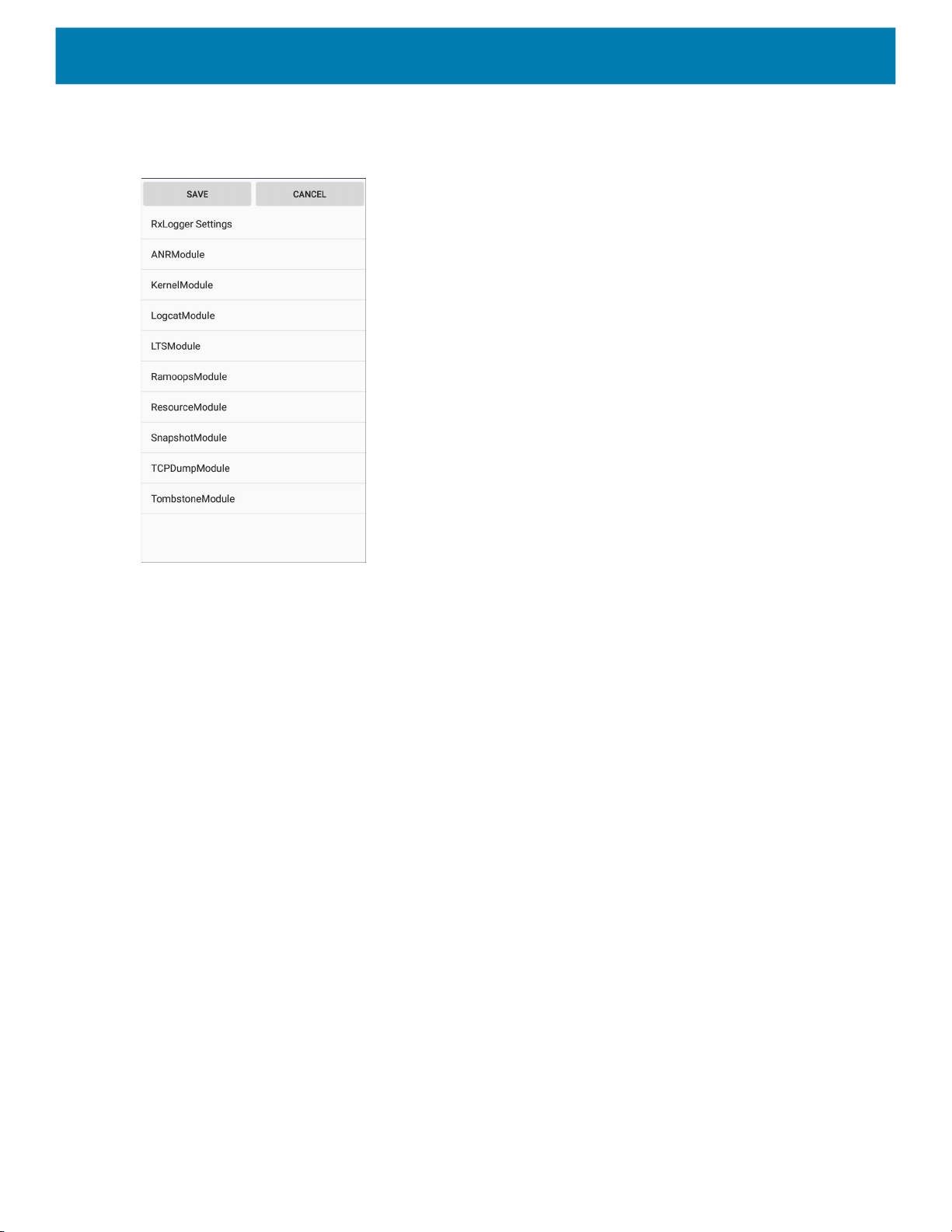
Settings
To open the configuration screen, from the RxLogger home screen touch Settings.
Figure 76 RxLogger Configuration Screen
RxLogger Settings
The RxLogger Settings module provides additional RxLogger settings.
• Enable notifications - Select to allow RxLogger notifications in the Status bar and Notification panel.
• Enable debug logs - Select to enable debug logs.
ANR Module
Application Not Responsive (ANR) indicates that a running application’s UI thread is not responding for a
specified time period. RxLogger is able to detect this condition and trigger a copy of the call stack trace of the
unresponsive application into the log directory. The event is also indicated in the high level CSV log.
• Enable Module - Enables logging for this module.
• Log path - Specifies the default log path to store the ANR log files.
• Collect Historic ANRs - Collects ANR trace files from the system.
Kernel Module
The Kernel Module captures kmsg from the system.
• Enable Module - Enables logging for this kernel module.
• Log path - Specifies the high level log path for storage of all kernel logs. This setting applies globally to all
kernel buffers.
• Kernel Log filename - Specifies the base log filename for this kernel buffer. The current file count is
appended to this name.
• Max Kernel log file size - Specifies the maximum size, in megabytes, of an individual log file.
• Kernel Log interval - Sets the interval, in seconds, on which to flush the log buffer to the file.
78

Settings
• Kernel Log file count - Specifies the number of log files to keep and rotate through. Each log file is subject
to the max log size option.
• Enable System Timestamp in Kernel Log - Enables system timestamps in kernel logs.
• System Timestamp Interval - Sets the interval, in seconds, between system timestamps.
• Enable Logcat Integration override - Enables logcat integration overrides.
Logcat Module
Logcat is an essential debugging tool on Android devices. RxLogger provides the ability to record data from all
four of the available logcat buffers. The Logcat plug-in can collect data from multiple logcat buffers provided by
the system, which are the main, event, radio, and system buffers. Each of the settings are available for each
buffer independently unless otherwise noted.
• Enable Module - Enables logging for this module.
• Log path - Specifies the high level log path for storage of all logcat logs. This setting applies globally to all
logcat buffers.
• Enable main logcat - Enables logging for this logcat buffer.
• Main Log interval (sec) - Sets the interval, in seconds, on which to flush the log buffer to the file.
• Main Log filename - Specifies the base log filename for this logcat buffer. The current file count is
appended to this name.
• Main Log file count - Specifies the number of log files to keep and rotate through. Each log file is
subject to the max log size option.
• Main log file size (MB) - Specifies the maximum size, in megabytes, of an individual log file.
• Main log filter - Custom logcat filter to run on the main buffer.
• Enable event logcat - Enables event logging for this logcat buffer.
• Event log interval (sec) - Sets the interval, in seconds, on which to flush the log buffer to the file.
• Event log filename - Specifies the base log filename for this logcat buffer. The current file count is
appended to this name.
• Event log file count - Specifies the number of log files to keep and rotate through. Each log file is
subject to the max log size option.
• Event log file size (MB) - Specifies the maximum size, in kilobytes, of an individual log file.
• Event log filter - Custom logcat filter to run on the event buffer.
• Enable radio logcat - Enables logging for this logcat buffer.
• Radio log interval (sec) - Sets the interval, in seconds, on which to flush the log buffer to the file.
• Radio log filename - Specifies the base log filename for this logcat buffer. The current file count is
appended to this name.
• Radio log file count - Specifies the number of log files to keep and rotate through. Each log file is
subject to the max log size option.
• Radio log file size (MB) - Specifies the maximum size, in kilobytes, of an individual log file.
• Radio log filter -Custom logcat filter to run on the radio buffer.
79

Settings
• Enable system logcat - Enables logging for this logcat buffer.
• System log interval (sec) - Sets the interval, in seconds, on which to flush the log buffer to the file.
• System log filename - Specifies the base log filename for this logcat buffer. The current file count is
appended to this name.
• System log file count - Specifies the number of log files to keep and rotate through. Each log file is
subject to the max log size option.
• System log file size (MB) - Specifies the maximum size, in kilobytes, of an individual log file.
• System log filter - Custom logcat filter to run on the system buffer.
• Enable crash logcat- Enables logging for this crash logcat buffer.
• Crash log interval (sec) - Sets the interval, in seconds, on which to flush the log buffer to the file.
• Crash log filename - Specifies the base log filename for this logcat buffer. The current file count is
appended to this name.
• Crash log file count - Specifies the number of log files to keep and rotate through. Each log file is
subject to the max log size option.
• Crash log file size (MB) - Specifies the maximum size, in megabytes, of an individual log file.
• Crash log filter - Custom logcat filter to run on the crash buffer.
• Enable combined logcat - Enables logging for this logcat buffer.
• Enable main buffer - Enable or disable the addition of the main buffer into the combined logcat file.
• Enable event buffer - Enable or disable the addition of the event buffer into the combined logcat file.
• Enable radio buffer - Enable or disable the addition of the radio buffer into the combined logcat file.
• Enable system buffer - Enable or disable the addition of the system buffer into the combined logcat file.
• Enable crash buffer - Enable or disable the addition of the crash buffer into the combined logcat file.
• Combine log interval (sec) - Sets the interval, in seconds, on which to flush the log buffer to the file.
• Combined log filename - Specifies the base log filename for this logcat buffer. The current file count is
appended to this name.
• Combined log file count - Specifies the number of log files to keep and rotate through. Each log file is
subject to the max log size option.
• Combined log file size (MB) - Specifies the maximum size, in megabytes, of an individual log file.
• Combined log filter - Custom logcat filter to run on the combined buffer.
LTS Module
The LTS (Long Term Storage) Module captures data over a long duration of time without losing any data.
Whenever a file is done being written, LTS saves it as a GZ file in an organized path for later use.
• Enable Module - Enables logging for this module.
• Storage Directory - Specifies the high level log path for storage of all logcat logs. This setting applies
globally to all logcat buffers.
Ramoops Module
The Ramoops Module captures the last kmsg from the device.
• Enable Module - Enables logging for this module.
• Log path - Specifies the high level log path for storage of all ramoops logs. This setting applies globally to
all Ramoops buffers.
• Base filename - Specifies the base log filename for this kernal buffer. The current file count is appended to
this name.
80

Settings
• Ramoops file count - Specifies the number of log files to keep and rotate through. Each log file is subject
to the log size option.
Resource Module
The Resource Module captures device information and system statistics at specified intervals. The data is
used to determine the health of the device over a period of time.
• Enable Module - Enables logging for this module.
• Log Path - Specifies the high level log path for storage of all resource logs. This setting applies globally to
all resource buffers.
• Resource Log interval - Sets the interval, in seconds, on which to flush the log buffer to the file.
• Resource Log file size - Specifies the maximum size, in megabytes, of an individual log file.
• Resource Log file count - Specifies the number of log files to keep and rotate through. Each log file is
subject to the max log size option.
• Power - Enables or disables the collection of Battery statistics.
• System Resource- Enables or disables the collection of System Resource information.
• Network - Enables or disables the collection of Network status.
• Bluetooth - Enables or disables the collection of Bluetooth information.
• Light - Enables or disables the collection of ambient light level.
• Heater - Not supported.
Snapshot Module
The Snapshot Module collects detailed device statistics at an interval to see detailed device information.
• Enable Module - Enables logging for this module.
• Log Path - Specifies the base path to use to store the snapshot files
• Log filename - Specifies the base filename for all the snapshot files. The current file count is appended to
this name.
• Log Interval (sec) - Specifies the interval, in seconds, on which to invoke a detailed snapshot.
• Snapshot file count - The maximum number of Snapshot files to keep at any one time.
• Top - Enables or disables the running of the
• CPU Info - Enables detailed per process CPU logging in the snapshot.
• Memory Info - Enables logging of detailed per process memory usage in the snapshot.
• Battery Info - Enables logging of detailed power information including battery life, on time, charging, and
wake locks.
• Wake Locks - Enables or disables the collection of the sys/fs wake_lock information.
• Time in State - Enables or disables the collection of the sys/fs cpufreq for each core.
• Processes - Enables dumping the complete process list in the snapshot.
• Threads - Enables dumping all processes and their threads in the snapshot.
• Properties - Enables dumping of all system properties on the device. This includes build/version
information as well as state information.
• Interfaces - Enables or disables the running of the
top command for data collection.
netcfg command for data collection.
• IP Routing Table - Enables or disables the collection of the net route for data collection.
• Connectivity - Enables or disables the running of the
• Wifi - Enables or disables the running of the
dumpsys wifi command for data collection.
dumpsys connectivity command for data collection.
81

Settings
• File systems - Enables dumping of the available volumes on the file system and the free storage space for
each.
• Usage stats - Enables dumping of detailed usage information for each package on the device. This
includes the number of starts and duration of each run.
TCPDump Module
The TCPDump Module captures TCP data that happens over the device’s networks.
• Enable Module - Enables logging for this module.
• Log path - Specifies the location to store the TCPDump output log files.
• Base filename - Specifies the base filename to use when storing the TCPDump files. The index number of
the current log file is appended to the filename.
• Tcpdump file size (MB) - Specifies the maximum file size, in megabytes, for each log file created.
• Tcpdump file count - Specifies the number of log files to cycle through when storing the network traces.
Tombstone Module
The Tombstone Module collects tombstone (Linux Native Crashes) logs from the device.
• Enable Module - Enables logging for this module.
• Log path - Specifies the location to store the Tombstone output log files.
• Collect Historic tombstones - Collects new and existing tombstone files.
Configuration File
RxLogger configuration can be set using an XML file. The config.xml configuration file is located in the
RxLogger\config folder. Copy the file from the device to a host computer using a USB connection. Edit the
configuration file and then replace the XML file on the device. There is no need to stop and restart the
RxLogger service since the file change is automatically detected.
Enabling Logging
To enable logging:
1. Swipe the screen up and select .
2. Touch Start.
3. Touch .
Disabling Logging
To disable logging:
1. Swipe the screen up and select .
2. Touch Stop.
3. Touch .
82

Extracting Log Files
1. Connect the device to a host computer using an USB connection.
Settings
2. Using a file explorer, navigate to the
3. Copy the file from the device to the host computer.
4. Disconnect the device from the host computer.
RxLogger Utility
RxLogger Utility is a data monitoring application for viewing logs in the device while RxLogger is running. Logs
and RxLogger Utility features are accessed in the App View or the Overlay View.
App View
In App View, the user views logs in the RxLogger Utility.
Figure 77 App View
RxLogger folder.
Viewing Logs
To view logs:
83

Settings
1. Touch the Main Chat Head icon. The Overlay View screen appears.
Figure 78 Overlay View Screen
2. Touch a log to open it. The user can open many logs with each displaying a new sub Chat Head.
3. If necessary, scroll left or right to view additional Sub Chat Head icons.
4. Touch a Sub Chat Head to display the log contents.
Figure 79 Log File
84

Settings
Backup
RxLogger Utility allows the user to make a zip file of the RxLogger folder in the device, which by default
contains all the RxLogger logs stored in the device.
To save the backup data, touch BACKUP > Yes.
Figure 80 Backup Message
Archive Data
View all the RxLogger logs stored in the default RxLogger directory. Logs viewed in the Archive window are not
live.
Figure 81 Archive
To view the log files, touch ARCHIVE DATA and then touch a log file.
Overlay View
Use Overlay View to display RxLogger information while using other apps or on the home screen. Overlay
View is accessed using the Main Chat Head.
Initiating the Main Chat Head
To initiate the Main Chat Head:
85

Settings
1. Open RxLogger.
2. Touch > Toggle Chat Head. The Main Chat Head icon appears on the screen.
3. Touch and drag the Main Chat head icon to move it around the screen.
Removing the Main Chat Head
To remove the Main Chat Head icon:
1. Touch and drag the icon. A circle with an X appears.
2. Move the icon over the circle and then release.
Viewing Logs
To view logs:
1. Touch the Main Chat Head icon. The Overlay View screen appears.
Figure 82 Overlay View Screen
2. Touch a log to open it. The user can open many logs with each displaying a new sub Chat Head.
3. If necessary, scroll left or right to view additional Sub Chat Head icons.
86

Settings
4. Touch a Sub Chat Head to display the log contents.
Figure 83 Log File
Removing a Sub Chat Head Icon
To remove a sub chat Head icon, press and hold the icon until it disappears.
Backing Up In Overlay View
RxLogger Utility allows the user to make a zip file of the RxLogger folder in the device, which by default
contains all the RxLogger logs stored in the device.
The Backup icon is always available in Overlay View.
1. Touch . The Backup dialog box appears.
2. Touch Yes to create the back up.
About Phone
Use About phone settings to view information about the device. Swipe down from the Status bar to open the
Quick Access panel and then touch > System > About phone.
87

Settings
• Status - Touch to display the following:
• Battery status - Indicates if the battery is charging (on AC power) or discharging (on battery power).
• Battery level - Indicates the battery charge level.
• IP address - Displays the IP address of the device.
• Wi-Fi MAC address - Displays the Wi-Fi radio MAC address.
• Ethernet MAC address - Displays the Ethernet driver MAC address.
• Bluetooth address - Displays the Bluetooth radio Bluetooth address.
• Serial number - Displays the serial number of the device.
• Up time - Displays the time that the device has been running since being turned on.
• Battery Information - Displays information about the battery.
• SW components - Lists filenames and versions for various software on the device.
• Legal information - Opens a screen to view legal information about the software included on the device.
• Model - Displays the devices model number.
• Android version - Displays the operating system version.
• Android security patch level - Displays the security patch level date.
• Kernel version - Displays the kernel version.
• Build Fingerprint - Defines Device Manufacturer, Model, Android version and Build version together in one
location.
• Build number - Displays the software build number.
88

USB Communication
Introduction
This chapter provides information for transferring files between the device and a host computer.
Transferring Files with a Host Computer via USB
Connect the device to a host computer using a USB cradle to transfer files between the device and the
host computer.
When connecting the device to a host computer, follow the host computer’s instructions for connecting
and disconnecting USB devices, to avoid damaging or corrupting files.
Transferring Files
NOTE: Use Transfer files to copy files between the device (internal memory) and the host computer.
1. Place the device into a USB cradle or into the USB snap on cup.
2. Pull down the Notification panel and touch USB charging this device.
By default, Charge this device is selected.
Figure 84 Use USB to Dialog Box
3. Touch Transfer files.
4. On the host computer, open a file explorer application.
5. Locate the device as a portable device.
89

6. Open the Internal storage folder.
7. Copy files to and from the device or delete files as required.
Transferring Photos
To transfer photos using Photo Transfer Protocol:
NOTE: Use Photo Transfer Protocol (PTP) to copy photos from the internal memory to the host computer.
1. Place the device into a USB cradle.
2. Pull down the Notification panel and touch USB charging this device.
3. Touch Transfer photos (PTP).
4. On the host computer, open a file explorer application.
5. Open the Internal storage folder.
6. Copy or delete photos as required.
USB Communication
Disconnect from the Host Computer
To disconnect the device from the host computer:
CAUTION: Carefully follow the host computer’s instructions to disconnect USB devices correctly to avoid losing information.
1. On the host computer, unmount the device.
2. Remove the device from the cradle.
90

DataWedge
Introduction
This chapter applies to DataWedge on Android devices. DataWedge is an application that reads data,
processes the data and sends the data to an application.
Basic Scanning
Scanning can be performed using the following:
Barcode Capture with Imager
To capture barcode data:
1. Ensure that an application is open on the device and a text field is in focus (text cursor in text field).
2. Point the top of the device at a barcode.
3. Press and hold the Scan button or Trigger.
The red laser aiming pattern turns on to assist in aiming.
4. Ensure the barcode is within the area formed by the cross-hairs in the aiming pattern. The aiming
dot is used for increased visibility in bright lighting conditions.
The Scan LEDs light green and a beep sounds, by default, to indicate the barcode was decoded
successfully. Note that when the device is in Pick List Mode, the device does not decode the
barcode until the center of the crosshair touches the barcode.
Figure 85 Data Capture
5. Release the scan button or Trigger.
91

Profiles
DataWedge
6. The barcode content data appears in the text field.
DataWedge is based on profiles and plug-ins. A profile contains information on how DataWedge should
behave with different applications.
Profile information consists of:
• Associated application
• Input plug-in configurations
• Output plug-in configurations
• Process plug-in configurations.
Using profiles, each application can have a specific DataWedge configuration. For example, each user
application can have a profile which outputs scanned data in the required format when that application comes
to the foreground. DataWedge can be configured to process the same set of captured data differently based on
the requirements of each application.
DataWedge includes the following pre-configured profiles which support specific built-in applications:
• Visible profiles:
Some Zebra applications are capable of capturing data by scanning. DataWedge is pre-loaded with private
and hidden profiles for this purpose. There is no option to modify the private profiles.
Profile0
Profile0 can be edited but cannot be associated with an application. That is, DataWedge allows manipulation
of plug-in settings for Profile0 but it does not allow assignment of a foreground application. This configuration
allows DataWedge to send output data to any foreground application other than applications associated with
user-defined profiles when Profile0 is enabled.
Profile0 can be disabled to allow DataWedge to only send output data to those applications which are
associated in user-defined profiles. For example, create a profile associating a specific application, disable
Profile0 and then scan. DataWedge only sends data to the application specified in the user-created profile.
This adds additional security to DataWedge enabling the sending of data only to specified applications.
Plug-ins
• Profile0 - created automatically the first time DataWedge runs. Generic profile used when there are no
user created profiles associated with an application.
• Launcher - enables scanning when the Launcher is in foreground.
• DWDemo - provides support for the DWDemo application.
A plug-in is a software module utilized in DataWedge to extend its functionality to encompass technologies
such as barcode scanning. The plug-ins can be categorized into three types based on their operations:
• Input Plug-ins
• Output Plug-ins
• Process Plug-ins.
92

Input Plug-ins
An Input Plug-in supports an input device, such as a barcode scanner contained in, or attached to the device.
DataWedge contains base plug-ins for these input devices.
Barcode Scanner Input Plug-in – The Barcode Scanner Input Plug-in is responsible for reading data from the
integrated barcode scanner and supports different types of barcode readers including laser, imager and
internal camera. Raw data read from the barcode scanner can be processed or formatted using Process
Plug-ins as required. DataWedge has built-in feedback functionality for the barcode scanner to issue user
alerts. The feedback settings can be configured according to user requirement.
Process Plug-ins
Process Plug-ins are used in DataWedge to manipulate the received data according to the requirement,
before sending to the foreground application via the Output Plug-in.
• Basic Data Formatting Process Plug-in – The Basic Data Formatting Plug-in allows DataWedge to add a
prefix and/or a suffix to the captured data before passing it to an Output Plug-in.
• Advanced Data Formatting Process Plug-in – The Advanced Data Formatting Plug-in allows
DataWedge to apply rules (actions to be performed based on defined criteria) to the data received via an
input plug-in before passing it to an Output Plug-in.
DataWedge
Output Plug-ins
Output Plug-ins are responsible for sending the data from Input Plug-ins to a foreground application on the
device.
• Keystroke Output Plug-in – The Keystroke Output Plug-in collects and sends data received from the Input
Plug-in to the foreground applications by emulating keystrokes.
• Intent Output Plug-in – The Intent Output Plug-in collects and sends data received from the Input Plug-ins
to foreground applications using the Android Intent mechanism.
• IP Output Plug-in – The IP Output Plug-in collects and sends data received from the Input Plug-ins to a
host computer via a network connection. Captured data can be sent over an IP network to a specified IP
address and port using either TCP or UDP transport protocols.
Profiles Screen
To launch DataWedge, swipe up from the bottom of the screen and touch . By default, the following profiles
appear:
• Profile0
• Launcher
• DWDemo
Profile0 is the default profile and is used when no other profile can be applied.
93
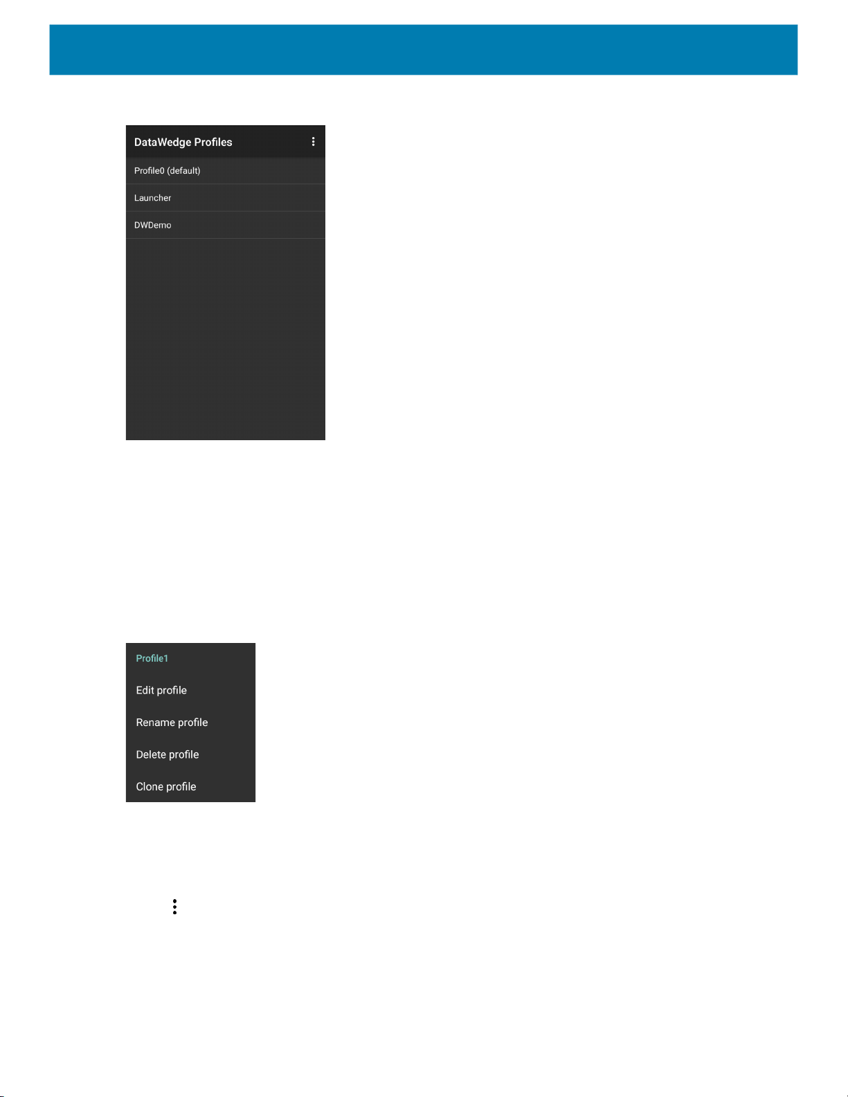
Figure 86 DataWedge Profiles Screen
DataWedge
Profile names are color coded. Enabled profiles are white and disabled profiles are gray.
To configure a profile touch the profile name.
Profile Context Menu
Touch and hold a profile to open a context menu that allows additional actions to be performed on the selected
profile.
Figure 87 Profile Context Menu
The profile context menu allows the profile to be edited (same as just tapping on a profile), renamed or deleted.
Options Menu
Touch to open the options menu.
94
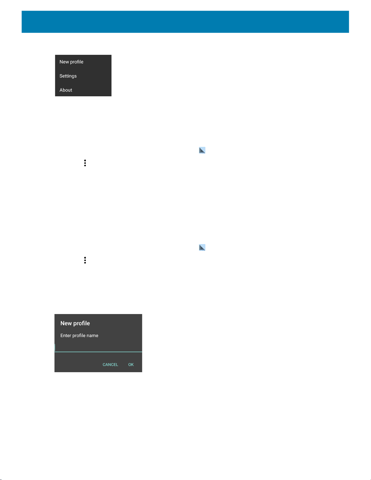
Figure 88 DataWedge Options Menu
The menu provides options to create a new profile, access to general DataWedge settings and DataWedge
version information.
Disabling DataWedge
1. Swipe up from the bottom of the screen and touch .
2. Touch .
3. Touch Settings.
4. Touch DataWedge enabled.
DataWedge
The blue check disappears from the checkbox indicating that DataWedge is disabled.
Creating a New Profile
To create a new profile:
1. Swipe up from the bottom of the screen and touch .
2. Touch .
3. Touch New profile.
4. In the New profile dialog box, enter a name for the new profile. It is recommended that profile names be
unique and made up of only alpha-numeric characters (A-Z, a-z, 0-9).
Figure 89 New Profile Name Dialog Box
5. Touch OK.
The new profile name appears in the DataWedge profile screen.
Profile Configuration
To configure the Profile0 or a user-created profile, touch the profile name.
95

DataWedge
Figure 90 Profile Configuration Screen
The configuration screen lists the following sections:
• Profile enabled
• Applications
• Data Capture Plus (DCP)
• Barcode Input
• Keystroke output
• Intent Output
• IP Output.
Associating Applications
Use Applications option to associate applications with this profile. User created profiles should be associated
with one or more applications and its activities.
1. Touch Associated apps. A list of applications/activities associated with the profile displays. Initially the list
does not contain any applications/activities.
96

Figure 91 Associated Apps Screen
DataWedge
2. Touch .
3. Touch New app/activity.
Figure 92 Select Application Menu
4. In the Select application screen, select the desired application from the list.
5. In the Select activity menu, selecting the activity adds that application/activity combination to the
associated application list for that profile. Selecting * as the activity results in all activities within that
application being associated to the profile. During operation, DataWedge tries to match the specific
application/activity combinations with the foreground application/activity before trying to match the general
application/* combinations.
6. Touch .
97

Figure 93 Selected Application/Activity
DataWedge
Data Capture Plus
Data Capture Plus (DCP) is a DataWedge feature that enables the user to initiate data capture by touching a
designated part of the screen. A variable screen overlay acts like a scan button.
Figure 94 Minimized Data Capture Panel
DCP Button
The DataWedge profile configuration screen allows the user to configure how the DCP appears on the screen
once the particular profile is enabled. The DCP is hidden by default. Enabling DCP option displays seven
additional configuration parameters.
98
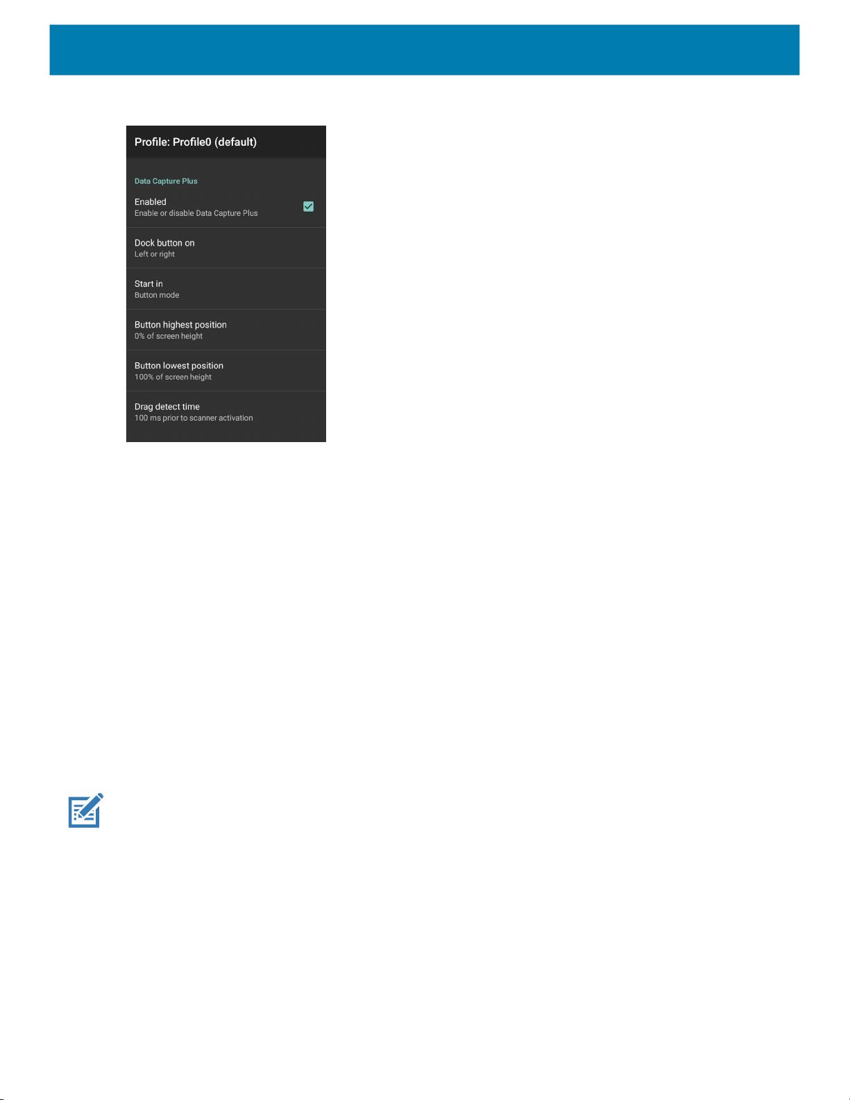
Figure 95 Data Capture Panel Settings
DataWedge
• Enable - Select to enable Data Capture Plus (default - disabled).
• Dock button on - Select position of the button.
• Left or right - Allows user to place the button on either the right or left edge of the screen.
• Left only - Places the button on left edge of the screen.
• Right only - Places the button on the right edge of the screen.
• Start in - Select the initial DCP state.
• Fullscreen mode - DCP covers the whole screen.
• Button mode - DCP displays as a circular button on the screen and can be switched to fullscreen mode.
• Button only mode - DCP displays as a circular button on the screen and cannot be switched to
fullscreen mode.
• Button highest position - Select the top of the range the user is allowed to move the DCP, given as a
percent of the screen height (default - 0).
• Button lowest position - Select the bottom of the range the user is allowed to move the DCP, given as a
percent of the screen height (default - 100).
• Drag detect time - Select the time in milliseconds that the scanner waits before activating scanner. This
allows the user to drag the button without initiating scanner (default - 100 ms, maximum 1000 ms).
NOTE: The DCP does not appear if the scanner is disabled in the profile even though the Enabled option is set.
In Button mode, the user can place DCP in full screen mode by dragging the button over Fullscreen mode.
The overlay covers the screen.
99

Figure 96 Maximized DCP
DataWedge
Swipe down to return to button mode.
Barcode Input
Use the Barcode Input options to configure the Barcode Scanner Input Plug-in for the profile.
Enabled
Enables or disables this plug-in. A check in the checkbox indicates that the plug-in is enabled.
Scanner Selection
Configures which scanning device to use for barcode data capture when the profile is active. For Bluetooth
scanners, if the device was not previously paired, a pairing barcode displays prior to automatic connection.
• Auto (2D Barcode Imager) - The software automatically determines the best scanning device.
• Camera Scanner - Scanning is performed with the rear-facing camera.
• 2D Barcode Imager - Scanning is performed using the 2D Imager.
• Bluetooth Scanner - Scanning is performed using the optional Bluetooth scanner.
• RS6000 Bluetooth Scanner - Scanning is performed using the RS6000 Bluetooth scanner.
• DS3678 Bluetooth Scanner - Scanning is performed using the DS3678 Bluetooth scanner.
• LI3678 Bluetooth Scanner - Scanning is performed using the DS3678 Bluetooth scanner.
• DS2278 Bluetooth Scanner - Scanning is performed using the DS2278 Bluetooth scanner.
• DS8178 Bluetooth Scanner - Scanning is performed using the DS8178 Bluetooth scanner.
Auto Switch to Default on Event
This feature configures DataWedge to select an external scanner as the default scanning device immediately
upon connection and revert to a built-in scanner when the external scanner is disconnected. External scanners
100
 Loading...