

Page 1
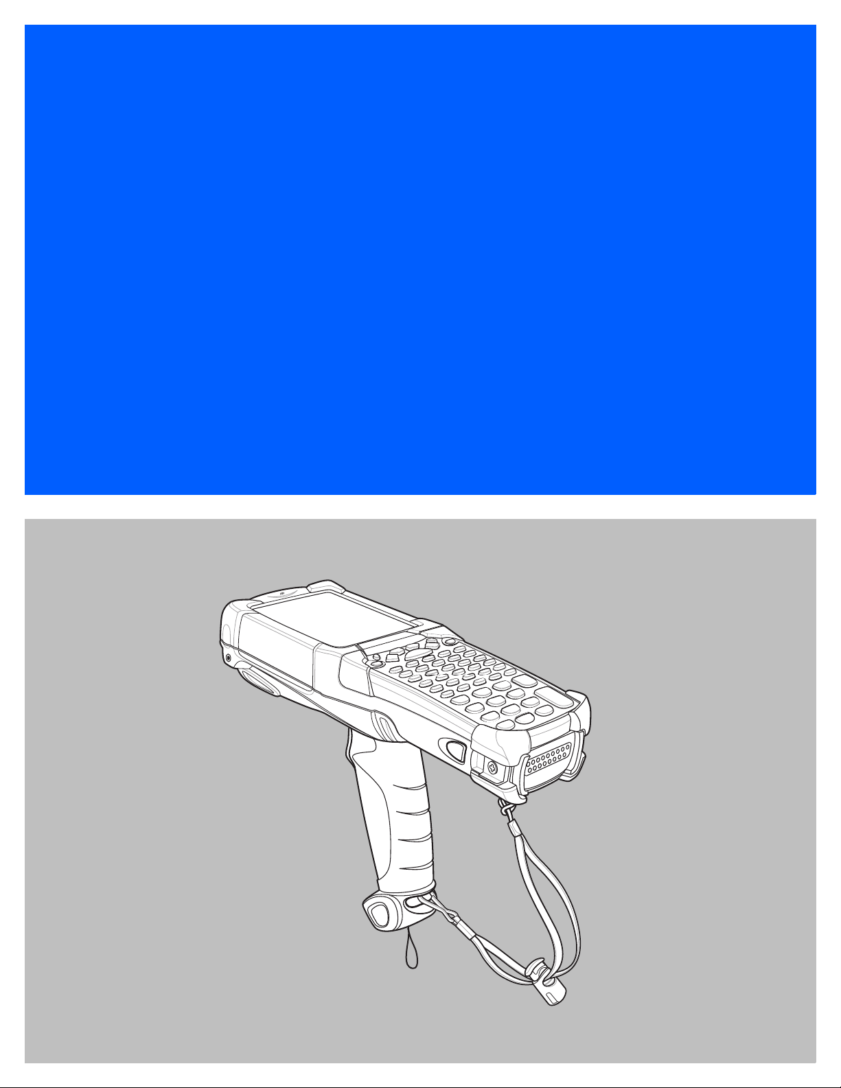
MC92N0-G
USER GUIDE
Page 2

Page 3

MC92N0-G
User Guide
72E-162536-03
Rev B
April 2015
Page 4

ii MC92N0-G User Guide
No part of this publication may be reproduced or used in any form, or by any electrical or mechanical means,
without permission in writing from Zebra. This includes electronic or mechanical means, such as photocopying,
recording, or information storage and retrieval systems. The material in this manual is subject to change
without notice.
The software is provided strictly on an “as is” basis. All software, including firmware, furnished to the user is on
a licensed basis. Zebra grants to the user a non-transferable and non-exclusive license to use each software
or firmware program delivered hereunder (licensed program). Except as noted below, such license may not be
assigned, sublicensed, or otherwise transferred by the user without prior written consent of Zebra. No right to
copy a licensed program in whole or in part is granted, except as permitted under copyright law. The user shall
not modify, merge, or incorporate any form or portion of a licensed program with other program material, create
a derivative work from a licensed program, or use a licensed program in a network without written permission
from Zebra. The user agrees to maintain Zebra’s copyright notice on the licensed programs delivered
hereunder, and to include the same on any authorized copies it makes, in whole or in part. The user agrees not
to decompile, disassemble, decode, or reverse engineer any licensed program delivered to the user or any
portion thereof.
Zebra reserves the right to make changes to any software or product to improve reliability, function, or design.
Zebra does not assume any product liability arising out of, or in connection with, the application or use of any
product, circuit, or application described herein.
No license is granted, either expressly or by implication, estoppel, or otherwise under any Zebra Technologies
Corporation, intellectual property rights. An implied license only exists for equipment, circuits, and subsystems
contained in Zebra products.
Page 5

Revision History
Changes to the original manual are listed below:
Change Date Description
-01 Rev. A 12/2012 Initial Release.
-02 Rev. A 05/31/13 Add Windows Embedded Handheld support.
-03 Rev. A 12/01/14 Zebra Rebranding
-03 Rev. B 4/15 Zebra Rebranding
iii
Page 6

iv MC92N0-G User Guide
Page 7

Table of Contents
Revision History ......................................................................................................................................... iii
About This Guide
Introduction ........................................................................................................................................... ix
Documentation Set ......................................................................................................................... ix
Configurations....................................................................................................................................... x
Software Versions................................................................................................................................. x
AKU Version for Windows Embedded Handheld Devices.............................................................. xi
OEM Version................................................................................................................................... xi
BTExplorer Software....................................................................................................................... xi
Fusion Software.............................................................................................................................. xi
Chapter Descriptions ............................................................................................................................ xi
Notational Conventions......................................................................................................................... xii
Related Documents and Software ........................................................................................................ xii
Service Information............................................................................................................................... xiii
Chapter 1: Getting Started
Introduction .......................................................................................................................................... 1-1
Unpacking ............................................................................................................................................ 1-2
Getting Started ..................................................................................................................................... 1-2
Installing the Main Battery ................................................................................................................... 1-2
Charging the Battery ............................................................................................................................ 1-3
Charging the Main Battery and Memory Backup Battery ............................................................... 1-3
Charging Spare Batteries ............................................................................................................... 1-4
Removing the Main Battery ............................................................................................................ 1-5
Starting the MC92N0-G ....................................................................................................................... 1-5
Calibrating the Screen ......................................................................................................................... 1-6
Checking Battery Status ...................................................................................................................... 1-6
MC92N0-G Strap ................................................................................................................................. 1-6
Battery Management ........................................................................................................................... 1-7
Battery Saving Tips ........................................................................................................................ 1-7
Changing the Power Settings ........................................................................................................ 1-7
Changing the Display Backlight Settings ....................................................................................... 1-7
Page 8

vi MC92N0-G User Guide
Changing the Keypad Backlight Settings ....................................................................................... 1-8
Turning Off the Radios ......................................................................................................................... 1-8
On Windows Embedded Handheld Devices .................................................................................. 1-8
On Windows CE Devices ............................................................................................................... 1-8
WLAN Radio ............................................................................................................................ 1-8
Bluetooth Radio with StoneStreet One Stack Enabled ............................................................ 1-9
Chapter 2: Operating the MC92N0-G
Introduction .......................................................................................................................................... 2-1
Windows CE 7.0 .................................................................................................................................. 2-1
Start Menu ..................................................................................................................................... 2-2
Control Panel ................................................................................................................................. 2-4
Windows Embedded Handheld ........................................................................................................... 2-5
Finger Scrolling .............................................................................................................................. 2-5
Home Screen ................................................................................................................................. 2-5
Classic Today Screen .............................................................................................................. 2-7
Status Bar ................................................................................................................................ 2-8
Tile Bar ..................................................................................................................................... 2-10
Start Screen ............................................................................................................................. 2-10
Speaker Icon ............................................................................................................................ 2-14
Locking the MC92N0-G ....................................................................................................................... 2-14
Locking without PIN or Password .................................................................................................. 2-14
Locking with Simple PIN ................................................................................................................ 2-15
Locking with Strong Password ....................................................................................................... 2-15
Password Locking Setup ............................................................................................................... 2-16
LED Indicators ..................................................................................................................................... 2-17
Keypads ......................................................................................................................................... 2-18
Entering Data ....................................................................................................................................... 2-18
Using the Power Button ....................................................................................................................... 2-19
Wireless LAN ....................................................................................................................................... 2-19
Windows CE Devices ..................................................................................................................... 2-19
Windows Embedded Handheld Devices ........................................................................................ 2-20
Connecting to the Internet .............................................................................................................. 2-21
Supported Applications ........................................................................................................................ 2-21
Fusion Setup ........................................................................................................................................ 2-22
Interactive Sensor Technology ............................................................................................................ 2-25
Power Management ....................................................................................................................... 2-25
Display Orientation ......................................................................................................................... 2-25
Free Fall Detection ......................................................................................................................... 2-25
Using a Wired Headset ........................................................................................................................ 2-25
Using a Bluetooth Headset .................................................................................................................. 2-26
Resetting the MC92N0-G .................................................................................................................... 2-26
Windows CE Devices ..................................................................................................................... 2-26
Performing a Warm Boot ......................................................................................................... 2-26
Performing a Cold Boot ............................................................................................................ 2-26
Windows Embedded Handheld Devices ........................................................................................ 2-27
Performing a Warm Boot ......................................................................................................... 2-27
Performing a Cold Boot ............................................................................................................ 2-27
Battery Health ...................................................................................................................................... 2-27
Page 9

Table of Contents vii
Waking the MC92N0-G ........................................................................................................................ 2-28
Chapter 3: Data Capture
Scan LED Indicators ............................................................................................................................ 3-1
Laser Scanning .................................................................................................................................... 3-1
Scanning Considerations ............................................................................................................... 3-2
Imaging ................................................................................................................................................ 3-2
Operational Modes ......................................................................................................................... 3-3
Imager Scanning ............................................................................................................................ 3-3
Image Capture ............................................................................................................................... 3-4
DataWedge .......................................................................................................................................... 3-5
Enable DataWedge ........................................................................................................................ 3-5
Disable DataWedge ....................................................................................................................... 3-5
ScanSamp2 Example .......................................................................................................................... 3-5
ImagerSample ..................................................................................................................................... 3-6
Using the RS507 Hands-free Imager ................................................................................................... 3-6
Chapter 4: Using Bluetooth
Introduction .......................................................................................................................................... 4-1
Adaptive Frequency Hopping .............................................................................................................. 4-1
Security ................................................................................................................................................ 4-2
Security Mode 3 (Link Level Encryption) ....................................................................................... 4-2
Microsoft Bluetooth Stack ........................................................................................................ 4-2
StoneStreet One Bluetooth Stack ............................................................................................ 4-2
Bluetooth Configuration ....................................................................................................................... 4-2
Bluetooth Power States ....................................................................................................................... 4-3
Cold Boot ....................................................................................................................................... 4-3
Warm Boot ............................................................................................................................... 4-4
Suspend ................................................................................................................................... 4-4
Resume .................................................................................................................................... 4-4
Device Information ......................................................................................................................... 4-5
FIPS Configuration ......................................................................................................................... 4-5
Device Status ................................................................................................................................. 4-6
Using Microsoft Bluetooth Stack with Windows Embedded Handheld ................................................ 4-7
Turning the Bluetooth Radio Mode On and Off .............................................................................. 4-7
Enabling Bluetooth ................................................................................................................... 4-7
Disabling Bluetooth .................................................................................................................. 4-7
Discovering Bluetooth Device(s) .................................................................................................... 4-7
Available Services .......................................................................................................................... 4-8
Object Push Services via Beam ............................................................................................... 4-8
Serial Port Services ................................................................................................................. 4-9
ActiveSync Using Serial Port Services .................................................................................... 4-10
Using Microsoft Bluetooth Stack with Windows CE 7.0 ....................................................................... 4-12
Power Modes ................................................................................................................................. 4-12
Discovering Bluetooth Device(s) .................................................................................................... 4-12
Available Services .......................................................................................................................... 4-13
Using Bluetooth StoneStreet One Bluetooth Stack ............................................................................. 4-14
Turning the Bluetooth Radio Mode On and Off .............................................................................. 4-14
Page 10

viii MC92N0-G User Guide
Disabling Bluetooth (Windows CE) .......................................................................................... 4-14
Enabling Bluetooth (Windows CE) ........................................................................................... 4-14
Disabling Bluetooth (Windows Embedded Handheld) ............................................................. 4-14
Enabling Bluetooth (Windows Embedded Handheld) .............................................................. 4-14
Modes ............................................................................................................................................ 4-15
Wizard Mode ............................................................................................................................ 4-15
Explorer Mode .......................................................................................................................... 4-15
Discovering Bluetooth Device(s) .................................................................................................... 4-15
Available Services .......................................................................................................................... 4-18
File Transfer Services .............................................................................................................. 4-18
Connecting to the Internet Using an Access Point ................................................................... 4-20
Dial-Up Networking Services ................................................................................................... 4-21
Add a Dial-up Entry .................................................................................................................. 4-22
Object Exchange Push Services .............................................................................................. 4-23
Headset Services ..................................................................................................................... 4-27
Serial Port Services ................................................................................................................. 4-28
ActiveSync Using Serial Port Services .................................................................................... 4-28
Personal Area Network Services ............................................................................................. 4-29
A2DP/AVRCP Services ........................................................................................................... 4-29
Connect to a HID Device ......................................................................................................... 4-30
Pairing with Discovered Device(s) ................................................................................................. 4-30
Bluetooth Settings .......................................................................................................................... 4-32
Device Info Tab ........................................................................................................................ 4-32
Services Tab ............................................................................................................................ 4-32
Security Tab ............................................................................................................................. 4-35
Discovery Tab .......................................................................................................................... 4-36
Virtual COM Port Tab ............................................................................................................... 4-36
HID Tab .................................................................................................................................... 4-37
Profiles Tab .............................................................................................................................. 4-37
System Parameters Tab .......................................................................................................... 4-37
Miscellaneous Tab ................................................................................................................... 4-37
Chapter 5: Accessories
Introduction .......................................................................................................................................... 5-1
Secure Device (SD) Card .................................................................................................................... 5-5
Single Slot Serial/USB Cradle ............................................................................................................. 5-6
Four Slot Ethernet Cradle .................................................................................................................... 5-8
Four Slot Charge Only Cradle ............................................................................................................. 5-9
Four Slot Spare Battery Charger ......................................................................................................... 5-10
Magnetic Stripe Reader ....................................................................................................................... 5-11
Attaching and Removing ................................................................................................................ 5-11
Setup .............................................................................................................................................. 5-12
Battery Charging Indicators ........................................................................................................... 5-13
Serial/USB Connection .................................................................................................................. 5-13
Using the MSR ............................................................................................................................... 5-13
Cable Adapter Module ......................................................................................................................... 5-15
Attaching and Removing ................................................................................................................ 5-15
Setup .............................................................................................................................................. 5-16
Battery Charging Indicators ........................................................................................................... 5-17
Page 11

Table of Contents ix
Serial/USB Connection .................................................................................................................. 5-17
Universal Battery Charger (UBC) Adapter ........................................................................................... 5-18
Inserting and Removing a Battery .................................................................................................. 5-18
Battery Charging Indicators ........................................................................................................... 5-18
Modem Dongle .................................................................................................................................... 5-20
Setup .............................................................................................................................................. 5-21
Connecting to the MC92N0-G .................................................................................................. 5-21
Connecting to the Single Slot Serial/USB Cradle .................................................................... 5-22
Forklift Cradle ...................................................................................................................................... 5-23
MC92N0-G Insertion and Removal ................................................................................................ 5-25
Using the Locking Mechanism ................................................................................................. 5-26
Connecting External Devices ......................................................................................................... 5-26
Supported Scanners ............................................................................................................................ 5-27
Chapter 6: Maintenance & Troubleshooting
Introduction .......................................................................................................................................... 6-1
Maintaining the MC92N0-G ................................................................................................................. 6-1
Battery Safety Guidelines .................................................................................................................... 6-1
Cleaning ............................................................................................................................................... 6-2
Approved Cleanser Active Ingredients ........................................................................................... 6-2
Harmful Ingredients ........................................................................................................................ 6-3
Cleaning Instructions ..................................................................................................................... 6-3
Special Cleaning Notes .................................................................................................................. 6-3
Materials Required ......................................................................................................................... 6-3
Cleaning the MC92N0-G ................................................................................................................ 6-3
Housing .................................................................................................................................... 6-3
Display ..................................................................................................................................... 6-3
Scanner Exit Window ............................................................................................................... 6-3
Connector ................................................................................................................................ 6-3
Cleaning Cradle Connectors .......................................................................................................... 6-4
Cleaning Frequency ....................................................................................................................... 6-4
Troubleshooting ................................................................................................................................... 6-5
MC92N0-G ..................................................................................................................................... 6-5
Four Slot Spare Battery Charger ................................................................................................... 6-8
Single Slot Serial/USB Cradle ........................................................................................................ 6-8
Cable Adapter Module ................................................................................................................... 6-9
Magnetic Stripe Reader ................................................................................................................. 6-10
Appendix A: Specifications
Technical Specifications ...................................................................................................................... A-1
MC92N0-G ..................................................................................................................................... A-1
Appendix B: Keypads
Introduction .......................................................................................................................................... B-1
28-Key Keypad .............................................................................................................................. B-2
43-Key Keypad .............................................................................................................................. B-5
53-Key Keypad .............................................................................................................................. B-8
Page 12

x MC92N0-G User Guide
3270 Emulator Keypad .................................................................................................................. B-11
5250 Emulator Keypad .................................................................................................................. B-14
VT Emulator Keypad ...................................................................................................................... B-17
Keypad Special Functions ............................................................................................................. B-20
Special Characters ......................................................................................................................... B-21
Page 13

About This Guide
Introduction
This guide provides information about using the MC92N0-G mobile computer and accessories.
NOTE Screens and windows pictured in this guide are samples and can differ from actual screens.
Documentation Set
The documentation set for the MC92N0-G is divided into guides that provide information for specific user needs.
•
MC92N0-G Quick Start Guide - describes how to get the MC92N0-G mobile computer up and running.
•
MC92N0-G User Guide - describes how to use the MC92N0-G mobile computer.
•
MC92N0-G Integrator Guide - describes how to set up the MC92N0-G mobile computer and the
accessories.
•
MC92N0-G Regulatory Guide - provides all regulatory, service and EULA information for the MC92N0-G
mobile computer.
•
Enterprise Mobility Developer Kit (EMDK) Help File - provides API information for writing applications.
Page 14

x MC92N0-G User Guide
Configurations
This guide covers the following configurations:
Configuration
MC92N0-G
Standard
MC92N0-G
Standard
MC92N0-G
Premium
MC92N0-G
Premium
1
Condensation Resistant configurations utilize desiccant located inside the MC92N0-G to capture internal moisture that forms when they are
carried from a warm humid environment to a cold environment.
Operating
System
Windows®
Embedded
Compact 7.0
®
Windows
Embedded
Handheld
Windows
Embedded
Compact 7.0
Windows®
Embedded
Handheld
®
Radios Display Memory
WLAN:
802.11a/b/g/n
WPAN: Bluetooth
WLAN:
802.11a/b/g/n
WPAN: Bluetooth
WLAN:
802.11a/b/g/n
WPAN: Bluetooth
WLAN:
802.11a/b/g/n
WPAN: Bluetooth
3.7”
QVGA /
VGA
Color
3.7”
QVGA
Color
3.7”
QVGA /
VGA
Color
3.7”
QVGA
Color
512 MB
RAM/
2 GB Flash
512 MB
RAM/
2 GB Flash
1 GB RAM/
2 GB Flash
1 GB RAM/
2 GB Flash
Data
Capture
Laser, Long
Range Laser,
Standard
Range Imager
(SR) or Long
Range Imager
Laser, Long
Range Laser,
Standard
Range Imager
(SR) or Long
Range Imager
Laser, Long
Range Laser,
Standard
Range Imager
(HD, DL, SR)
or Long Range
Imager
Laser, Long
Range Laser,
Standard
Range Imager
(HD, DL, SR)
or Long Range
Imager
Keypads Other
28-key,
43-key,
53-key,
VT, 3270,
5250
Emulators
28-key,
43-key,
53-key,
VT, 3270,
5250
Emulators
28-key,
43-key,
53-key,
VT, 3270,
5250
Emulators,
53-key
High
Visibility
28-key,
43-key,
53-key,
VT, 3270,
5250
Emulators,
53-key
High
Visibility
Interactive
Sensor
Technology,
Condensation
Resistant
Interactive
Sensor
Technology,
Condensation
Resistant
1
1
Software Versions
This guide covers various software configurations and references are made to operating system or software
versions for:
•
AKU version
•
OEM version
•
BTExplorer version
•
Fusion version.
AKU Version for Windows Embedded Handheld Devices
To determine the Adaptation Kit Update (AKU) version on a Windows Embedded Handheld device, tap Start >
Settings > System > About > Version.
Page 15

About This Guide xi
The second line lists the operating system version and the build number. The last part of the build number
represents the AKU number. For example, Build 23103.5.3.3 indicates that the device is running AKU version
5.3.3.
OEM Version
To determine the OEM software version:
On Windows Embedded Handheld devices, tap Start > Settings > System > System Information > System.
On Windows CE devices, tap Start > Settings > Control Panel > System Information > System.
BTExplorer Software
NOTE By default, the Microsoft Bluetooth stack is enabled. BTExplorer application is only available when the
StoneStreet One Bluetooth stack is enabled. Refer to the MC92N0-G Integrator Guide for information on
selecting the Bluetooth stack.
To determine the BTExplorer software version:
On Windows Embedded Handheld devices, tap Start > BTExplorer > Menu > About.
On Windows CE devices, tap BTExplorer icon > Show BTExplorer > File > About.
Fusion Software
To determine the Fusion software version:
On Windows Embedded Handheld devices, tap Start > Wireless Companion > Wireless Status > Versions.
On Windows CE devices, tap Wireless Strength icon > Wireless Status > Versions or tap Start > Programs >
Fusion > Wireless Status > Versions.
Chapter Descriptions
Topics covered in this guide are as follows:
•
Chapter 1, Getting Started, provides information on getting the mobile computer up and running for the first
time.
•
Chapter 2, Operating the MC92N0-G, explains how to use the mobile computer. This includes instructions for
powering on and resetting the mobile computer, entering and capturing data.
•
Chapter 3, Data Capture, explains how to capture data using the laser scanner.
•
Chapter 4, fUsing Bluetooth, explains how to perform Bluetooth functionality on the mobile computer.
•
Chapter 5, Accessories, describes the accessories available for the mobile computer and how to use the
accessories with the mobile computer.
•
Chapter 6, Maintenance & Troubleshooting, includes instructions on cleaning and storing the mobile
computer, and provides troubleshooting solutions for potential problems during mobile computer operation.
•
Appendix A, Specifications, includes a table listing the technical specifications for the mobile computer.
•
Appendix B, Keypads, contains the keypad functions/special characters for the keypads.
Page 16

xii MC92N0-G User Guide
Notational Conventions
The following conventions are used in this document:
•
“Mobile computer” refers to the Zebra MC92N0-G hand-held computer.
•
Italics are used to highlight the following:
• Cha
• Related documents
•
Bold text is used to highlight the following:
• Dialo
• Drop-down list and list box names
• Check box and radio button names
• Icons on a screen
• Key names on a keypad
• Button names on a screen.
•
Bullets (•) indicate:
• Action items
• L
• Lists of required steps that are not necessarily sequential.
pters and sections in this guide
g box, window and screen names
ists of alternatives
•
Sequential lists (e.g., those that describe step-by-step procedures) appear as numbered lists.
Related Documents and Software
The following documents provide more information about the MC92N0-G mobile computers.
•
MC92N0-G Regulatory Guide, p/n 72-161752-xx
•
MC92N0-G Integrator Guide, p/n 72E-162537-xx
•
Enterprise Mobility Developer Kits (EMDKs), available at: http://www.zebra.com/support.
•
Device Configuration Package (DCP for MC92N0c70) and Platform SDK (PSDK92N0c70) for MC92N0-G
with Windows CE 7.0, available at:
•
ActiveSync software, available at: http://www.microsoft.com.
For the latest version of this gu
ide and all guides, go to: http://www.zebra.com/support.
Service Information
If you have a problem with your equipment, contact Zebra Global Customer Support for your region. Contact
information is av
When contacting support, please have the following information available:
ailable at: http://www.zebra.com/support.
http://www.zebra.com/support.
•
Serial number of the unit
Page 17

About This Guide xiii
•
Model number or product name
•
Software type and version number.
Zebra responds to calls by email, telephone or fax within the time limits set forth in support agreements.
If your problem cannot be solved by Zebra Global Customer Support, you may need to return your equipment for
servicing and will be given specific directions. Zebra is not responsible for any damages incurred during shipment if
the approved shipping container is not used. Shipping the units improperly can possibly void the warranty.
If you purchased your Zebra business product from a Zebra business partner, contact that business partner for
support.
Page 18

xiv MC92N0-G User Guide
Page 19
Chapter 1 Getting Started
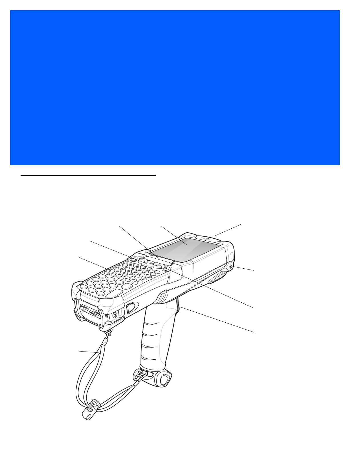
Handstrap
Keypad
Indicator LED Bar Touch Screen
Microphone
Headphone Jack
Scan Button
Power Button
Trigger
Introduction
This chapter explains how to install and charge the batteries, replace the strap and start the MC92N0-G for the first
time.
.
Figure 1-1
MC92N0-G
Page 20

1 - 2 MC92N0-G User Guide
Unpacking
Carefully remove all protective material from around the MC92N0-G and save the shipping container for later
storage and shipping.
Verify that you received all equipment listed below:
•
mobile computer
•
lithium-ion battery
•
strap, attached to the MC92N0-G
•
stylus, in the stylus silo
•
Regulatory Guide.
Inspect the equipment for damage. If you are missing any equipment or if you find any damaged equipment,
contact the Zebra Global Interactive Center immediately. See
Getting Started
page xii for contact information.
In order to start using the MC92N0-G for the first time:
•
install the main battery
•
charge the main battery and backup battery
•
start the MC92N0-G
•
configure the MC92N0-G.
The main battery can be charged before or after it is installed. Use one of the spare battery chargers to charge the
main battery (out of the MC92N0-G), or one of the cradles to charge the main battery installed in the MC92N0-G.
Installing the Main Battery
Before using the MC92N0-G, install a lithium-ion battery by sliding the battery into the MC92N0-G as shown in
Figure 1-2.
NOTE Ensure the battery is fully inserted. Two audible clicks can be heard as the battery is fully inserted. A partially
inserted battery may result in unintentional data loss.
When a battery is fully inserted in a MC92N0-G for the first time, upon first power up, the device boots and powers
on automatically.
Page 21

Getting Started 1 - 3
Figure 1-2
Charging the Battery
Installing the Main Battery
CAUTION Ensure that you follow the guidelines for battery safety described in Battery Safety Guidelines on page 6-1.
Charging the Main Battery and Memory Backup Battery
Before using the MC92N0-G for the first time, charge the main battery until the amber charge indicator light
remains lit (see Table 1-1 on page 1-4 for charge status indications). The main battery
four hours. The MC92N0-G can be charged using a cradle, the CAM, or the MSR with the appropriate power
.
supply
The MC92N0-G is also equipped with a
whether or not the MC92N0-G is operating or is in suspend mode. The memory backup battery retains data in
memory for at least 30 minutes when the MC92N0-G's main battery is removed or fully discharged. When the
MC92N0-G is used for the first time or after the memory backup battery has fully discharged, the memory backup
battery requires approximately 15 hours to fully charge. Do not remove the main battery from the MC92N0-G for 15
hours to ensure that the memory backup battery fully charges. If the main battery is removed from the MC92N0-G
or the main battery is fully discharged, the memory backup battery completely discharges in several hours.
When the main battery reaches a very low battery state, the combination of main battery and backup battery
etains data in memory for at least 72 hours.
r
memory backup battery which automatically charges from the main battery
fully charges in less than
NOTE Do not remove the main battery within the first 15 hours of use. If the main battery is removed before the
backup battery is fully charged, data may be lost.
Use the following to charge batteries:
Page 22

1 - 4 MC92N0-G User Guide
•
Cradles: The MC92N0-G slips into the cradles for charging the battery in the MC92N0-G (and spare
batteries, where applicable). For detailed cradle setup and charging procedures refer to the MC92N0-G
Integrator Guide.
• Single Slot Serial/USB Cradle.
• Four Slot Ethernet Cradle
• Four Slot Charge Only Cradle.
•
Accessories: The MC92N0-G snap-on accessories provide charging capability, when used with one of the
accessory charging cables. For detailed snap-on setup and charging procedures refer to the MC92N0-G
Integrator Guide.
• CAM
• MSR.
•
Chargers: The MC92N0-G spare battery charging accessories are used to charge batteries that are removed
from the MC92N0-G. For detailed spare battery charging accessories setup and charging procedures refer to
the MC92N0-G Integrator Guide.
• Single Slot Serial/USB Cradle
• Four Slot Spare Battery Charger
• Universal Battery Charger (UBC) Adapter.
NOTE To achieve the best battery life in MC92N0-Gs with multiple radios, turn off the radios that are not being used.
See Turning Off the Radios on page 1-8 for more information.
To charge the main battery:
1. Ensure the accessory used to charge the main battery is connected to the appropriate power source.
2. Insert the MC92N0-G into a cradle or attach the appropriate snap-on module.
3. The MC92N0-G starts to charge automatically. The amber charge LED, in the Indicator LED Bar, lights to
indicate the charge status. See Table 1-1 for charging indications.
The main battery usually fully charges in less than four hours.
Table 1-1
Off MC92N0-G not in cradle or connected to a CAM or MSR. MC92N0-G not placed correctly.
Fast Blinking Amber Error in charging; check placement of the MC92N0-G.
Slow Blinking Amber MC92N0-G is charging.
Solid Amber Charging complete.
MC92N0-G LED Charge Indicators
LED Indication
Charger is not powered.
Note: When the battery is initially inserted in the MC92N0-G, the amber LED flashes once if
the battery power is low or the battery is not fully inserted.
Charging Spare Batteries
Use the following three accessories to charge spare batteries:
•
Single Slot Serial/USB Cradle
Page 23
Getting Started 1 - 5
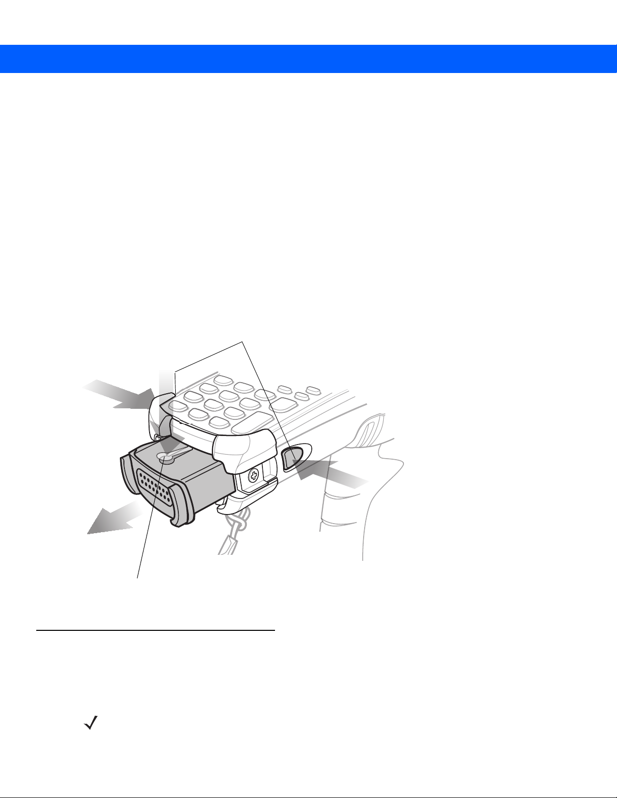
Primary Battery Releases
Secondary Battery Release
•
Four Slot Spare Battery Charger
•
UBC Adapter.
Refer to Chapter 5, Accessories for information on charging a spare battery using an accessory.
Removing the Main Battery
To remove the main battery:
1. Prior to removing the battery, press the red Power button. The PowerKey Action screen appears.
2. Ta p Safe Battery Swap.
3. The Indicator LED Bar lights red.
4. When the Indicator LED turns off, press the primary battery releases. The battery partially ejects from the
MC92N0-G.
5. Press the secondary battery release, on top of the battery, and slide the battery out of the MC92N0-G.
1
2
3
Figure 1-3
Removing the Main Battery
Starting the MC92N0-G
Press the red Power button to turn on the MC92N0-G. If the MC92N0-G does not power on, perform a cold boot.
See
Resetting the MC92N0-G on page 2-26.
1
NOTE When a battery is fully inserted in a MC92N0-G for the first time, upon the MC92N0-G’s first power up, the
device boots and powers on automatically.
Page 24

1 - 6 MC92N0-G User Guide
When the MC92N0-G is powered on for the first time, it initializes its system. The splash screen appears for a short
period of time.
Calibrating the Screen
To calibrate the screen so the cursor on the touch screen aligns with the tip of the stylus:
1. Using the stylus carefully press and briefly hold the tip of stylus on the center of each target that appears on the
screen.
NOTE To re-calibrate the screen at anytime, press FUNC + ESC on the MC92N0-G to launch the calibration
screen application.
2. Repeat as the target moves around the screen or press ESC to cancel.
Checking Battery Status
To check the charge level of the main battery or backup battery:
•
On Windows CE devices, tap Start > Settings > Control Panel > Power to display the Battery Status
window.
•
On Windows Embedded Handheld devices, tap Start > Settings > System > Power to display the Power
window.
To save battery power, set the MC92N0-G to turn off after a specified number of minutes.
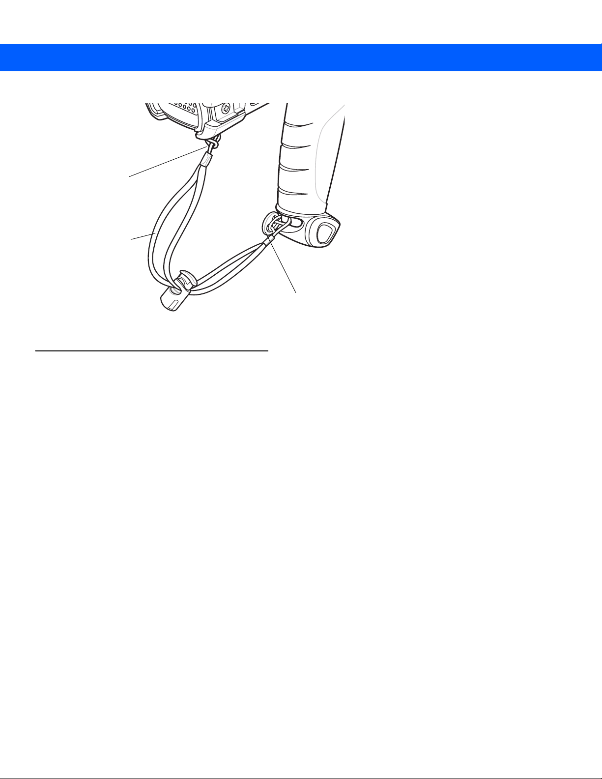
MC92N0-G Strap
The strap may be moved to either the left or right side of the MC92N0-G to suit user preferences.
To reposition the strap:
1. Slip the button through the end loop and remove from the handle.
2. Open strap loop and slide the handstrap through the loop.
3. Slide the loop out of the connector post.
4. Reverse the procedure to re-attach the strap. Two strap connectors are provided on the MC92N0-G’s main
body. The handstrap may be attached to either connector.
Page 25
Getting Started 1 - 7
Button
Strap Loop
Handstrap
Figure 1-4
Reposition the Strap
Battery Management
Battery Saving Tips
•
Leave the MC92N0-G connected to AC power at all times when not in use.
•
Set the MC92N0-G to turn off after a short period of non-use.
•
Set the display to turn off or dim backlight.
•
Set the keyboard backlight to turn off after a short period of non-use.
•
Turn off all wireless radio activity when not in use.
•
Power off the MC92N0-G when charging to charge at a faster rate.
Changing the Power Settings
To set the MC92N0-G to turn off after a short period of non-use:
1. On Windows CE devices, tap Start > Settings > Control Panel > Power > Advanced.
or
On Windows Embedded Handheld devices, tap Start > Settings > System > Power > Advanced.
2. Select the On battery power: Turn off device if not used for: check box and select a value from the
drop-down list box.
3. Ta p OK.
Changing the Display Backlight Settings
To change the display backlight settings in order to conserve more battery power:
Page 26

1 - 8 MC92N0-G User Guide
1. On Windows CE devices, tap Start > Settings > Control Panel > Backlight > Battery Power.
or
On Windows Embedded Handheld devices, tap Start > Settings > System > Backlight > Battery Power.
2. Select the On battery power: Disable backlight if not used for: check box and select a value from the
drop-down list box.
3. Tap the Brightness tab.
4. Tap the Disable backlight check box to completely turn off the display backlight.
5. Use the slider to set the brightness of the backlight. Set it to a low value to save battery power.
6. Ta p OK.
Changing the Keypad Backlight Settings
To change the keypad backlight settings in order to conserve more battery power:
1. On Windows CE devices, tap Start > Settings > Control Panel > Keylight > Battery Power.
or
On Windows Embedded Handheld devices, tap Start > Settings > System > Keylight > Battery Power.
2. Select the On Battery Power: Disable keylight if not used for: check box and select a value from the
drop-down list box.
3. Ta p Advanced.
4. Tap the Disable keylight check box to completely turn off the display backlight.
5. Ta p OK.
Turning Off the Radios
On Windows Embedded Handheld Devices
Windows Embedded Handheld devices include Wireless Manager, which provides a simple method of enabling,
disabling, and configuring all the device’s wireless capabilities in one place.
To open Wireless Manager, tap the Status Bar and then the Connectivity icon and select Wireless Manager or
tap Start > Settings > Connections > Wireless Manager.
•
To enable or disable a wireless connection, tap its blue bar.
•
To enable or disable all wireless connections, tap and hold the All bar.
•
To configure settings for a connection, tap Menu.
On Windows CE Devices
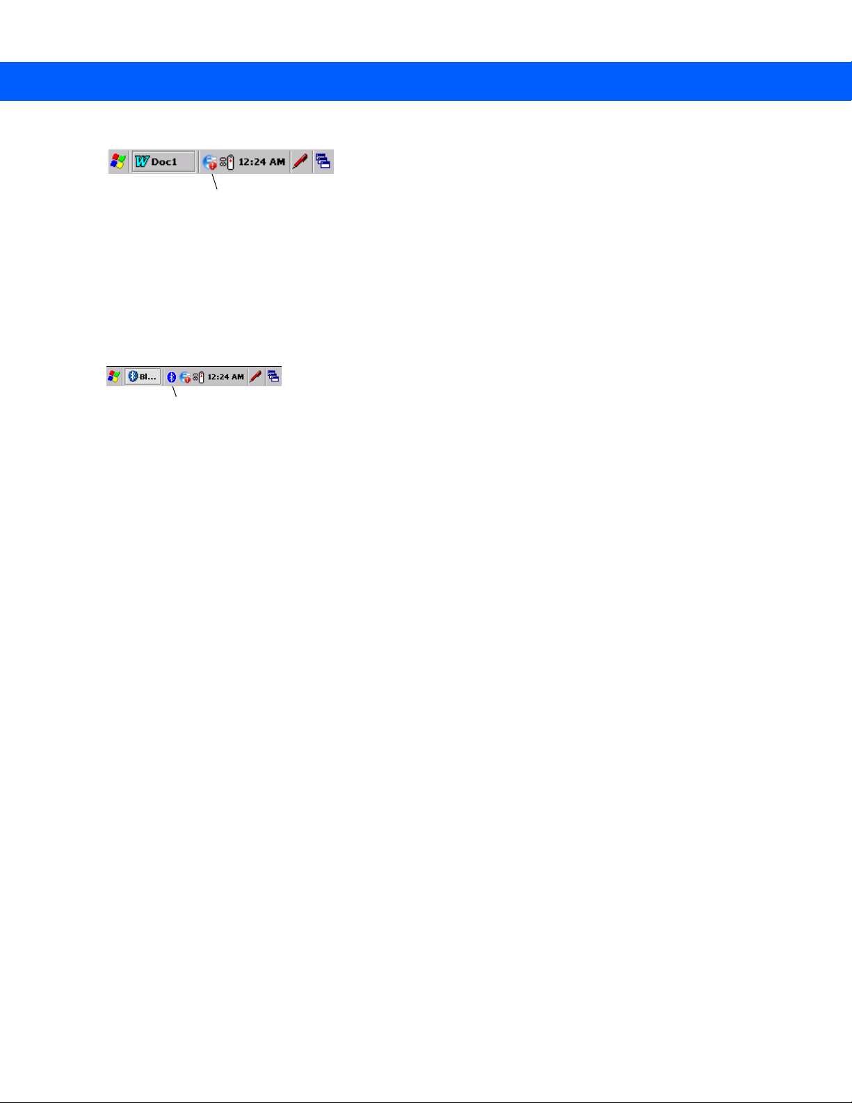
WLAN Radio
To turn off the WLAN radio tap the Fusion Signal Strength icon on the task tray and select Disable Radio. A red
X appears across the icon indicating that the radio is disabled (off).
Page 27
Getting Started 1 - 9
Fusion Signal Strength Icon
Bluetooth Icon
Figure 1-5
Fusion Signal Strength Icon
To turn the radio back on, tap the Fusion Signal Strength icon on the task tray and select Enable Radio. The red
X disappears from the icon indicating that the radio is enabled (on).
Bluetooth Radio with StoneStreet One Stack Enabled
To turn off the Bluetooth radio, tap the Bluetooth icon in the task tray and select Disable Bluetooth.
Figure 1-6
To turn on the Bluetooth radio, tap the Bluetooth icon in the task tray and select Enable Bluetooth.
Bluetooth Icon
Page 28

1 - 10 MC92N0-G User Guide
Page 29

Chapter 2 Operating the MC92N0-G
Start Button
Open Programs
Desktop Button
Status Icons
Introduction
This chapter explains the physical buttons, status icons and controls on the MC92N0-G, how to use the
MC92N0-G, including instructions for powering on and resetting, using the stylus and a headset, entering
information and data capture.
Windows CE 7.0
The Taskbar at the bottom of the window displays the active programs, current time, battery status and
communication status.
Figure 2-1
Status icons are shown in the taskbar to indicate present status of the MC92N0-G. Double tapping some status
icons displays the corresponding setup window and enables you to change or adjust its settings from the window.
Single tapping other status icons displays corresponding menus.
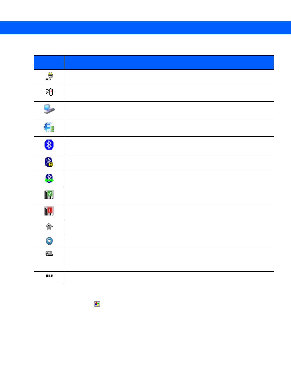
Table 2-1
Status
Icon
Task b ar
Status Icons
Clock:
Battery:
power.
Double tapping on this icon opens the
Description
Indicates the current time.
This icon indicates that the main battery is charging or that the terminal is operating on AC
Power Properties
window.
Page 30
2 - 2 MC92N0-G User Guide
ALT
Table 2-1
Status
Icon
Status Icons (Continued)
Description
AC Plug:
Battery:
The battery status icons provide the battery status in 10% increments from 10% to 100%.
Serial Connection:
cable.
Wireless Connection Status:
Bluetooth Enabled:
Bluetooth Disabled:
Bluetooth Communication:
device (BTExplorer only).
Indicates that the battery is fully charged and the MC92N0-G is running on external power.
This icon indicates that the battery is fully charged (100% charged).
It is displayed when the terminal is connected to a host computer with a serial
Indicates WLAN signal strength.
Indicates that the Bluetooth radio is on (BTExplorer only).
Indicates that the Bluetooth radio is off (BTExplorer only).
Indicates that the MC92N0-G is communicating with another Bluetooth
DataWedge Running:
DataWedge Idle:
Shift:
Indicates that the SHIFT button function is selected.
FUNC:
Indicates that the FUNC button function is selected.
CTRL:
Indicates that the CTRL button function is selected.
ALT:
Indicates that the ALT character selection is selected.
ALPHA:
Indicates that the MC92N0-G is in ALPHA button mode is selected.
Indicates that the DataWedge application is running.
Indicates that the DataWedge application is idle.
Start Menu
To open the Start menu, tap at the bottom left corner of the screen. Table 2-2 lists the default applications
available in the Progr
ams menu.
Page 31

Operating the MC92N0-G 2 - 3
Table 2-2
Icon Description Icon Description
Applications in the Programs Menu
BattSwap: Use to properly shutdown the
MC92N0 during battery replacement.
Video Player: Play back video files. Music Player: Play back audio files.
BTScanner CtlPanel: Set com port to
use with a Bluetooth scanner.
CtlPanel: View and change MC92N0-G
settings such as: Scanner Parameters,
Display Settings, Audio Settings, Printer
Settings, Date and Time Settings, Touch
Screen Settings, etc.
MotoBTUI: Pairs up bar code with the
MC92N0-G via Bluetooth and uses the
RS507 Hands-free Imager to capture the
bar code data.
Fusion Folder: Open the Wireless
Companion folder.
Command Prompt: Opens a DOS
command prompt window.
Internet Explorer: Browse Web and
WAP sites as well as download new
programs and files from the Internet.
Microsoft WordPad: Create
documents.
MSP Agent: Interacts with MSP agents
to collect monitoring and asset
information to enable the configuration,
provisioning, monitoring and
troubleshooting of the MC92N0-G. Refer
to the MC92N0-G Integrator Guide for
more information.
Remote Desktop Connection:
Windows NT server type computers and
use all of the programs that are available
on that computer from the MC92N0-G.
WarmBoot: Warm boots the MC92N0-G. Windows Explorer: Organize and
Log onto
Rapid Deployment Client:
software downloads from a Mobility
Services Platform Console FTP server to
the MC92N0-G.
Integrator Guide for more information.
Tel en tCE: Opens the Wavelink Telnet
client.
manage files on your device.
Refer to the MC92N0-G
Facilitates
Page 32

2 - 4 MC92N0-G User Guide
Control Panel
Table 2-3 lists the applications in the Control Panel.
Table 2-3
Icon Description Icon Description
Programs on the Control Panel
Backlight: Adjust the backlight
brightness and power settings.
Certificates:
certificates installed on the MC92N0-G.
Date/Time: Change date, time and time
zone information.
Volume & Sounds: Select the type of
actions for which to hear sounds and
customize notifications for different
events.
Error Reporting: Choose whether to
MC92N0-G collects software operation
information to use if a serious error
occurs.
Internet Options: Control how the
MC92N0-G connects to the internet.
See information about
Bluetooth Device Properties: Launch
the Bluetooth application.
DataWedge:
application. Icon appears after installation.
Dialing: Set dialing properties for
modem communication and change
telephony settings.
Display: Change desktop background,
appearance, backlight and brightness.
Input Panel: Switch input methods and
set input options.
IST Settings: Set the appropriate
settings for configuring the MC92N0-G’s
Interactive Sensor Technology.
Sample scanning
Keyboard: Change keyboard repeat
delay and rate.
Mouse: Adjust double-click sensitivity
for both the speed and timing.
Owner:
profiles.
PC Connection: Change settings for
connectivity of a host computer.
Regional Settings: Change how
numbers, currencies, dates and times
appear.
Screen Resolution: Sets the screen
resolution to either QVGA or VGA. See
MC92N0-G Integrator Guide for more
information.
Change owner’s personal
Keylight: Adjust keypad light settings.
Network and Dial-up Connections:
Connect to other computers, networks
and the Internet using a modem.
Password: Set a password for the
MC92N0-G.
Power: View and control MC92N0-G
power settings.
Remove Programs: Remove programs
installed on the MC92N0-G.
Stylus: Calibrate the touch screen and
adjust double-tap timing.
Page 33

Operating the MC92N0-G 2 - 5
Open the Start Menu
Tiles
Status Bar
Tod a y S cr e e n
Tile Bar
Table 2-3
Icon Description Icon Description
Programs on the Control Panel
System: V
change memory settings.
USBConfig: Configure the MC92N0-G
USB port.
iew system information and
Windows Embedded Handheld
The following section describes the operation of the Windows Embedded Handheld operating system.
Finger Scrolling
Windows Embedded Handheld adds finger scrolling capabilities to the display. Finger scrolling can be used to
scroll up and down web pages, documents, and lists such as the contacts list, file list, message list, calendar
appointments list, and more.
When finger scrolling, swipe or flic
screen. To scroll up, swipe your finger downward on the screen. To auto-scroll, flick your finger upward or
downward on the screen. Touch the screen to stop scrolling.
k your finger on the screen. To scroll down, swipe your finger upward on the
System Info: View information on the
MC92N0-G’s system components.
Home Screen
The default home screen on the MC92N0-G is the Windows Handheld Home screen. The Home screen contains a
Status Bar at the top of the screen and a Tile Bar at the bottom of the screen.
The Home screen is scrollable and contains a list of applicatio
Information Status bar highlights the application plug-in that is under it and provides additional information.
Figure 2-2
n plug-ins and an Information Status bar. The
Windows Embedded Handheld Home Screen
Touch and hold the screen with your finger and move the Home screen up and down. As the application names
ve under the Information Status bar, information relevant to that application appear in the bar.
mo
Page 34

2 - 6 MC92N0-G User Guide
Application Icon
Application Information
Figure 2-3
Moving Today Screen
Touch and hold the Information Status bar and move it up and down over an application name. Remove your finger
and the Information Status bar and application name center in the screen.
Figure 2-4
Moving Information Status Bar
Figure 2-5
To customize the Home sc
Information Bar Example
reen, tap > Settings > Today. On the horizontal scroll, use Appearance to
customize the background and the It
ems to change the display format.
Page 35

Operating the MC92N0-G 2 - 7
Tile Bar
Status Bar
Today Screen
Tas k Tr a y
Classic Today Screen
The user can change to the classic Today screen layout that is used in Windows Mobile 6.1.
Figure 2-6
To change to the classic view tap
Figure 2-7
Deselect the W
Classic Today Screen
> Settings > Home > Items.
Home Screen Settings
indows Default checkbox and select any of the other checkboxes and then tap .
The task bar at the bottom of the screen can contain the task tray icons listed in Table 2-4.
Table 2-4
Task Tray Icons
Icon Description
Wireless connection status:
Indicates WLAN signal strength and opens the Wireless Applications
menu.
Bluetooth Enabled:
Indicates that the Bluetooth radio is on (Displays only if the StoneStreet One
Bluetooth stack is enabled).
Page 36

2 - 8 MC92N0-G User Guide
ALT
Battery
Audio
Connectivity
Notifications
Battery
Clock
Table 2-4
Task Tray Icons (Continued)
Icon Description
Bluetooth Disabled:
Indicates that the Bluetooth radio is off (Displays only if the StoneStreet One
Bluetooth stack is enabled).
Bluetooth Communication:
Indicates that the MC92N0-G is communicating with another Bluetooth
device (Displays only if the StoneStreet One Bluetooth stack is enabled).
ActiveSync:
Indicates an active serial connection between the MC92N0-G and the development
computer.
DataWedge Running:
DataWedge Idle:
Shift:
Indicates that the SHIFT button function is selected.
FUNC:
Indicates that the FUNC button function is selected.
Indicates that the DataWedge application is running.
Indicates that the DataWedge application is idle.
CTRL:
Indicates that the CTRL button function is selected.
ALT:
Indicates that the ALT character selection is selected.
Status Bar
The Status Bar at the top of the screen displays the status icons listed in Table 2-5.
Figure 2-8
Table 2-5
Icon Description Icon Description
Notifications
Status Bar Icons
Status Bar Icons
Indicates a reminder of an upcoming calendar
event.
Notification that one or more instant messages
were received.
Page 37

Operating the MC92N0-G 2 - 9
Icon Bar
Table 2-5
Status Bar Icons (Continued)
Icon Description Icon Description
Notification that one or more e-mail/text
messages were received.
There are more notification icons than can be
displayed.
Connectivity
Connection is active. Connection is not active.
Synchronization is occurring. WLAN available.
WLAN in use.
Audio
All sounds are on. All sounds are off.
Battery
Battery is charging. Battery has a full charge.
Battery has a high charge. Battery has a medium charge.
Battery has a low charge. Battery has a very low charge.
Tap the Status Bar to display an Icon bar. Tap an icon to get additional notification or status information.
Figure 2-9
Icon Bar
Page 38

2 - 10 MC92N0-G User Guide
Table 2-6
Icon Bar Icons
Icon Description
Magnify: Enlarges the screen.
Connectivity: Displays the Connectivity dialog box.
Volume: Displays the Volume dialog box.
Power: Displays the Power window.
Clock & Alarms:
Opens the Clocks & Alarms window.
Tile Bar
The Tile Bar, located at the bottom of the screen, contains the Start tile to open the Start Menu. It also displays
tiles that vary depending upon the open application.
Figure 2-10
Tile Bar Examples
Start Screen
To open the Start screen, tap at the bottom left corner of the screen.
Swipe upward to view more program and folder icons.
Move often-used program and folder icons anywhere on the S
to move. Drag the icon to a new location and release.
Table 2-7 lists the default icons available on the Start screen.
Table 2-7
Icon Description Icon Description
Programs on the Start Screen
Home: Displays the Home screen. Tex t: Send an SMS text message.
Contacts: Keep track of friends and
colleagues.
Internet Explorer: Browse Web and
WAP sites as well as download new
programs and files from the Internet.
tart screen for easy access. Press and hold the icon
E-mail: Send an Email.
Battery Swap: Properly shuts down the
MC92N0-G during battery replacement.
Page 39

Operating the MC92N0-G 2 - 11
Table 2-7
Programs on the Start Screen (Continued)
Icon Description Icon Description
Calendar: Keep track of appointments
and create meeting requests.
Settings: Open the Settings folder.
Table 2-8 lists the default icons available
on the Settings folder.
Pictures & Videos: View and manage
pictures, animated GIFs, and video files.
Windows Media: Play back audio and
video files.
Getting Started: Launch the Getting
Started application.
Alarms: Set the device clock to the date
and time of your locale. Alarms can also
be set at specified days and times of a
week.
Marketplace: Purchase applications
from the Marketplace.
Windows Live: Use this mobile version
of Windows Live™ to find information on
the web.
MSN Money: Keep track of your
Messenger: Use this mobile version of
Windows Live Messenger.
Calculator: Perform basic arithmetic
and calculations, such as addition,
subtraction, multiplication, and division.
MSN Weather: Check the local weather.
finances.
Tasks: Keep track of your tasks. Games: Play games.
Office Mobile: Use the complete suite of
Microsoft
®
Office applications for your
Notes: Create handwritten or typed
notes, drawings, and voice recordings.
mobile device (Premium only).
File Explorer: Organize and manage
files on your device.
ActiveSync: Synchronize information
between the MC92N0-G and a host
computer or the Exchange Server.
Search Phone: Search contacts, data,
and other information on the MC92N0-G.
Refer to the Microsoft Applications for
Internet Sharing: Connect a notebook
computer to the Internet using the
MC92N0-G's data connection.
Windows Mobile 6 User Guide for more
information.
Help: Access on-line Help topics. Task Manager: Enables viewing of
memory and CPU allocations and stops
running processes. Refer to the
Microsoft Applications for Windows
Mobile 6 User Guide for more
information.
Adobe Reader: View pdf files. Wireless Companion: Open the
Wireless Companion folder.
Page 40

2 - 12 MC92N0-G User Guide
Table 2-7
Icon Description Icon Description
Programs on the Start Screen (Continued)
BTScanner CtlPanel: Set com port to
use with a Bluetooth scanner.
BT Information: Display information
about the Bluetooth radio and generate a
Bluetooth address bar code.
Remote Desktop Mobile:
Windows NT server type computers and
use all of the programs that are available
on that computer from the MC92N0-G.
RTLogExport: Use when instructed to
by Zebra support personnel to extract
real-time data to a log file. Alternately,
press F9 to extract the data to a log file.
The log file is located in the /ExportLogs
folder.
Log onto
BTExplorer: Manages StoneStreet One
Bluetooth connections. Refer to the
MC92N0-G Series MC92N0-G Integrator
Guide for more information. Appears
only if the StoneStreet One Bluetooth
stack is enabled.
MSP Agent: Interacts with MSP agents
to collect monitoring and asset
information to enable the configuration,
provisioning, monitoring and
troubleshooting of the MC92N0-G. Refer
to the MC92N0-G Integrator Guide for
more information.
Rapid Deployment Client:
software downloads from a Mobility
Services Platform Console FTP server to
the MC92N0-G.
Integrator Guide for more information.
Facilitates
Refer to the MC92N0-G
Table 2-8
Icon Description Icon Description
Setting Applications
Clock & Alarms:
the date and time of your locale. Alarms
can also be set at specified days and
times of a week.
Home:
Home screen and the information to
display on it.
Personal Folder:
setting applications.
System Folder:
applications.
Customize the appearance of the
Set the device clock to
Contains personal
Contains system setting
Lock:
Set a password for the MC92N0-G.
Sounds & Notifications:
for events, notifications, and more, and set
the type of notification for different events.
Connections Folder:
connection setting applications.
Enable sounds
Contains
Page 41

Operating the MC92N0-G 2 - 13
Table 2-8
Setting Applications (Continued)
Icon Description Icon Description
Connections Folder
Beam:
incoming beams.
Set the MC92N0-G to receive
Connections:
Set up one or more types of
modem connections for your device, such
as phone dial-up, Bluetooth, and more, so
that your device can connect to the
Internet or a private local network.
Bluetooth: Open the Microsoft or
StoneStreet One Bluetooth application,
set the MC92N0-G to visible mode and
scan for other Bluetooth devices in the
area.
Wi-Fi:
Setup wireless network connection
and customize settings.
Wireless Manager:
Enables or disables
Domain Enroll:
domain member for device management
and security. Refer to the Microsoft
Applications for Windows Mobile 6 User
Guide for more information.
USB to PC:
Enables or disables the
enhanced network connectivity.
the MC92N0-G’s wireless radios and
customizes Wi-Fi and Bluetooth settings.
Personal Folder
Make your device an AD
System Folder
Buttons:
About:
the Windows Handheld
Assign a program to a button.
View basic information such as
®
version and type
of processor used on the MC92N0-G.
Backlight:
Set display backlight
brightness and time-out settings.
Encryption:
Allow files on a storage card
to be encrypted. Encrypted files are
readable only on your device.
Error Reporting:
Enable or disable the
Microsoft’s error reporting function.
Keylight: Set keypad backlight time-out
settings.
Owner Information:
Enter personal
information on the MC92N0-G.
Certificates:
See information about
certificates installed on the MC92N0-G.
Customer Feedback:
Submit feedback on
the Windows Handheld 6 software.
DataWedge:
Sample scanning
application.
IST Settings: Set the appropriate setting
for configuring the device’s Interactive
Sensor Technology.
Memory:
Check the device memory
allocation status and memory card
information and stop currently running
programs.
Managed Programs:
Displays the
programs that were installed on the
MC92N0-G using Mobile Device
Manager.
Power:
Check battery power and set the
time-out for turning off the display to
conserve battery power.
Page 42

2 - 14 MC92N0-G User Guide
Table 2-8
Icon Description Icon Description
Setting Applications (Continued)
Remove Programs:
that you installed on the MC92N0-G.
Screen:
re-calibrate the screen, and change the
screen text size.
System Info: Displays the MC92N0-G’s
software and hardware information.
USBConfig:
USB port.
Change the screen orientation,
Configure the MC92N0-G
Remove programs
Regional Settings:
configuration to use, including the format
for displaying numbers, currency, date,
and time on the MC92N0-G.
Task Manager:
and processes.
UI Settings:
Sets Start menu grid view.
Speaker Icon
Adjust the system volume using the Speaker icon.
1. Tap the Status Bar and then tap the Speaker icon. The Volume dialog box appears.
Set the regional
Stop running programs
2. Tap and move the slide bar to adjust the volume.
3. Select the On or Off radio button to turn the speaker on or off.
NOTE Use can also adjust the system volume using the Sounds & Notifications window or by using the keypad.
Locking the MC92N0-G
Lock the MC92N0-G by disabling key presses and screen tap or by requiring a password.
Locking the MC92N0-G turns off keyboard and touch screen functionality
turned on and you want to prevent accidental key presses.
To lock the device, tap
Locking without PIN or Password
When the MC92N0-G is locked, the Lock screen appears.
. This is helpful when the MC92N0-G is
> .
Page 43

Operating the MC92N0-G 2 - 15
Figure 2-11
Slide the lock button left or right to unlock the screen.
Lock Screen
Locking with Simple PIN
When the MC92N0-G is locked, the Lock screen appears.
Figure 2-12
Enter the PIN and then tap Unlock.
Simple PIN Lock Screen
Locking with Strong Password
When the MC92N0-G is locked, the Lock screen appears.
Page 44

2 - 16 MC92N0-G User Guide
Figure 2-13
Strong Password Lock Screen
Enter the strong password and then tap Unlock.
Password Locking Setup
Use the Password window to set a password to disable unauthorized access to the MC92N0-G.
NOTE If the MC92N0-G is configured to connect to a network, use a strong (difficult to figure out)
password to help protect network security. Password cracking tools continue to improve and the
computers used to crack passwords are more powerful than ever.
1. Ta p > Settings > Lock.
Figure 2-14
2. Select Prompt if device unused for check box to enable password protection.
3. From the drop-down list, select a time value for the protection to take affect after non-use.
4. From the Password type: drop-down list, select either Simple PIN or Strong alphanumeric.
5. For a simple password, enter a four-digit password in the Password field.
Password Window
For a stronger password:
Page 45

a. Enter a seven character password in the Password: field. A strong password must contain at least seven
LED Indicator Bar
characters and contain at least three of the following: uppercase and lowercase letters, numerals, and
punctuation.
b. Re-enter the password in the Confirm: field.
6. Tap .
LED Indicators
The MC92N0-G has an LED Indicator Bar that contains LEDs that indicate scanning and charging status. Table 2-9
describes the LED indications.
Operating the MC92N0-G 2 - 17
Figure 2-15
Table 2-9
Solid Red Laser enabled, scanning/imaging in process.
Solid Green Successful decode/capture.
Slow Blinking Amber Main battery in MC92N0-G is charging.
Fast Blinking Amber Error in charging; check placement of the MC92N0-G.
Solid Amber Main battery in MC92N0-G is fully charged.
MC92N0-G LEDs Indicator Bar
MC92N0-G LED Indications
LED State Indication
Page 46

2 - 18 MC92N0-G User Guide
Single-hand Method
Two-hand Method
Keypads
The MC92N0-G has the following interchangeable modular keypads:
•
28-key keypad
•
43-key keypad
•
53-key keypad
•
3270 Emulator
•
5250 Emulator
•
VT Emulator.
Refer Appendix B, Keypads to for detailed information on each keypad.
Entering Data
When entering data on the keypad, use either the single-hand method or the two-hand method as shown in Figure
2-16.
Figure 2-16
Entering Data on the Keypad
Page 47

Using the Power Button
Press the red Power button to turn the MC92N0-G screen on and off (suspend mode). The MC92N0-G is on when
the screen is on and the MC92N0-G is in suspend mode when the screen is off. For more information, see
the MC92N0-G on page 1-5.
The Power button is also used to reset the MC92N0-G by performing a warm or cold boot.
On Windows CE devices:
• Warm Boot - Resets the MC92N0-G.
• Cold Boot - Resets the MC92N0-G, removes all added applications not stored in the Application folder and
restores all factory default settings.
•
On Windows Embedded Handheld devices:
• Warm Boot - Resets the MC92N0-G. Operating system and all applications are restarted. File storage is
preserved.
• Cold Boot - Resets the MC92N0-G. Operating system and all applications are restarted. File storage is
preserved. Normally only used when a warm boot does not initiate.
Operating the MC92N0-G 2 - 19
Starting
NOTE Applications that are added to the Application folder are not removed when a cold boot is performed. The
For information about booting the MC92N0-G, see Windows Embedded Handheld Devices on page 2-27.
Wireless LAN
NOTE By default, the WLAN is on when the MC92N0-G boots up. To set the WLAN radio to be off when
To configure the MC92N0-G, a set of wireless applications provide the tools to configure and test the wireless radio
in the MC92N0-G. Refer to the Wireless Fusion Suite User Guide for Version X2.01 for information on configuring
wireless profiles. Go to
page x to determine the Fusion version on the MC92N0-G.
Windows CE Devices
Tap the Signal Strength icon to display the Wireless Launcher menu.
Application folder is in flash memory.
the MC92N0-G boots up, see the MC92N0-G Integrator Guide.
http://www.zebra.com/support for the latest version of this guide. See Software Versions on
Page 48

2 - 20 MC92N0-G User Guide
Signal Strength Icon
Figure 2-17
Wireless Application Menu
Windows Embedded Handheld Devices
NOTE On devices with Windows Embedded Handheld, access the Wireless Launcher from the Home
screen. Select the Fusion plug-in and then tap the Fusion Menu button.
The interface to the Signal Strength icon and Wireless Launcher has changed in the Windows Embedded
Handheld default Today screen. To view the Wireless Launcher, select the Fusion plug-in on the Today screen
and tap the Fusion Menu soft key.
Figure 2-18
Functionality of this dialog is similar to the Wireless Launch menu. Drag the window up and down to view all menu
items. Tap the icon next to the item to open it.
Fusion Plug-in on Today Screen
Page 49

Operating the MC92N0-G 2 - 21
Wireless Launcher Window
Connecting to the Internet
To connect to the Internet on a WLAN when using Fusion Wireless Companion, ensure that the network card
settings is set to Internet:
1. Ensure Fusion is enabled and a profile is configured.
2. Tap > Settings > Connections > Wi-Fi.
3. In the My network card Connects to drop-down list, select The Internet.
4. Ta p OK.
Supported Applications
The Fusion menu items and their corresponding applications are summarized in Table 2-10.
Table 2-10
Find WLANs Invokes the
Manage Profiles Invokes the
Manage Certs Invokes the
Supported Applications
Application Description
Find WLANs
active in the area.
Manage Profiles
Editor Wizard
manage certificates used for authentication.
) to manage and edit the list of WLAN profiles.
Certificate Manager
application which displays a list of the WLANs
application (which includes the
application which allows the user to
Profile
Manage PACs Invokes the
of Protected Access Credentials used with Extensible Authentication
Protocol-Flexible Authentication via Secure Tunneling (EAP-FAST)
authentication.
Options Invokes the
Fusion option settings.
PAC Manager
Options
application which allows the user to configure the
application which helps the user manage the list
Page 50

2 - 22 MC92N0-G User Guide
Table 2-10
Wireless Status Invokes the
Wireless Diagnostics Invokes the
Log on/off Invokes the
Fusion Help Invokes Fusion Help application which provides on-device Help.
Fusion Setup
For detailed WLAN setup using Fusion, refer to the Wireless Fusion Enterprise Mobility Suite User Guide for
Version X2.01.
To setup WLAN using Fusion:
NOTE Obtain the proper WLAN configuration information from the system administrator prior to performing the
Supported Applications (Continued)
Application Description
Wireless Status
application which allows the user to view the
status of the current wireless connection.
Wireless Diagnostics
application which provides tools with
which to diagnose problems with the wireless connection.
Network Login
dialog which allows the user to log on to a
particular profile or to log off from the currently active profile
Fusion setup procedures.
The following setup procedure example shows setup of a WLAN using Wired Equivalent Privacy (WEP)
encryption.
1. Tap the > Wireless Companion > Wireless Launch > Manage Profiles. The Manage Profiles window
appears.
2. Tap and hold in the window and select Add from the pop-up menu. The Wireless LAN Profile Entry window
appears.
3. In the Profile Name text box enter a name for the profile.
4. In the ESSID text box enter the ESSID.
Figure 2-19
5. Ta p Next. The Operating Mode dialog box displays.
6. In the Operating Mode drop-down list, select Infrastructure or Ad-hoc.
Profile ID Dialog Box
Page 51

Operating the MC92N0-G 2 - 23
Figure 2-20
7. Ta p Next. The Security Mode dialog box displays.
8. In the Security Mode drop-down list, select Legacy (Pre-WPA).
Figure 2-21
9. In the Authentication drop-down list, select None.
10. Ta p Next. The Encryption dialog box displays.
11. In the Encryption Type drop-down list, select WEP-40 (40/24).
Operating Mode Dialog Box
Security/Authentication Dialog Box
Figure 2-22
12. Select the Pass-phrase or Hexadecimal Keys radio button to indicate whether a pass-phrase or hexadecimal
Encryption Dialog Box
keys will be entered on the next page.
13. Select the For added security - Mask characters entered check box to hide characters entered. Deselect
this to show characters entered.
14. Ta p Next.
Page 52

2 - 24 MC92N0-G User Guide
Figure 2-23
15. In the Edit Key drop-down list, select the key to enter.
16. In the Key field, enter 10 hexadecimal characters.
17. In the Confirm field, re-enter the key. When the keys match, a message appears indicating that the keys
WEP-40 WEP Keys Dialog Box
match.
18. Repeat for each WEP key.
19. In the Transmit Key drop-down list, select the key to transmit.
20. Ta p Next. The IPv4 Address Entry dialog box displays.
Figure 2-24
21. Ensure that all three check boxes are selected.
IP Address Entry Dialog Box
22. Ta p Next. The Battery Usage dialog box appears.
23. In the Battery Usage Mode dialog box select a power consumption option.
Figure 2-25
24. Ta p Next. The Performance Settings dialog box appears.
25. In the Performance Settings dialog box select either Optimize for Data or Optimize for Voice.
26. Ta p Save.
Battery Usage Dialog Box
Page 53

Interactive Sensor Technology
NOTE The Interactive Sensor Technology feature is only available on Premium configurations.
This section describes the functionality of the Interactive Sensor Technology (IST) feature on the MC92N0-G.
The IST supports the following features.
•
Power Management – manage power by configuring IST to control switching on/off the backlight, control
suspend mode of the MC92N0-G by monitoring motion and orientation.
•
Display Orientation – switch the screen orientation to either landscape or portrait depending on the
MC92N0-G orientation.
•
Free Fall Detection – monitors free fall duration and records the time and type of the drop event.
Power Management
The MC92N0-G orientation and motion sensitive data can be used as an indicator of MC92N0-G usage and can be
used to manage the battery power of the MC92N0-G. For example, IST can be configured to control the backlight
on and off functionality or go into suspend according to a user gesture by placing screen facing down. It can also
be used to keep the MC92N0-G active while it is in movement to prevent it from quickly going into suspend mode
while in use.
Operating the MC92N0-G 2 - 25
Display Orientation
The screen can be rotated between portrait and landscape modes automatically, depending on the physical
orientation of the MC92N0-G. For example, if the MC92N0-G is rotated 90° counterclockwise, IST rotates the
display counterclockwise 90° so that the screen display appears correct.
This functionality is achieved by monitoring screen angle and rotating the display to counter any changes. IST only
rotates the screen in multiples of 90°.
Free Fall Detection
IST continuously monitors gravitational force on the MC92N0-G according to its current position. When the
MC92N0-G free falls, IST detects the absence of gravitational force and records the event data if it detects a free
fall more than 450 ms, which may indicates nearly a one meter drop. This data can be used as an indicator of
potential abuse or misuse.
IST features a log for recording the free fall events. This log records the date, time and the time period of the free
fall.
Using a Wired Headset
You can use a mono headset for audio communication when an audio enabled application is used. To use a
headset, plug the headset jack into the audio connector on the side of the MC92N0-G. Ensure that the
MC92N0-G’s volume is set appropriately before putting the headset on. When a headset is plugged into the jack,
the speakerphone is muted.
Zebra recommends a 2.5mm jack headset. See Table 5-1 on page 5-1 for available Zebra headsets.
Page 54

2 - 26 MC92N0-G User Guide
Figure 2-26
Using a Headset (MC92N0-G Shown)
Using a Bluetooth Headset
Use a Bluetooth headset for audio communication when an audio enabled application is used. See Chapter 4,
fUsing Bluetooth for information on connecting a Bluetooth device to the MC92N0-G. Ensure that the MC92N0-G’s
volume is set appropriately before putting the headset on. When a Bluetooth headset is connected the
speakerphone is muted.
Resetting the MC92N0-G
Windows CE Devices
There are two reset functions, warm boot and cold boot. A warm boot restarts the MC92N0-G by closing all running
programs.
A cold boot also restarts the MC92N0-G, but erases all stored records and entries in RAM. Data saved in flash
memory or a memory card is not lost. In addition it returns formats, preferences and other settings to the factory
default settings.
Perform a warm boot first. This restarts the MC92N0-G and saves all stored records and entries. If the MC92N0-G
still does not respond, perform a cold boot.
Performing a Warm Boot
Hold down the Power button for approximately five seconds. As soon as the MC92N0-G starts to perform a warm
boot release the Power button.
Performing a Cold Boot
A cold boot restarts the MC92N0-G and erases all user stored records and entries that are not saved in flash
memory (Application and Platform folders) or a memory card. Never perform a cold boot unless a warm boot does
not solve the problem.
CAUTION Do not hold down any key, other than the Power button during a reset. Performing a cold boot restores
formats, preferences and other settings to the default settings.
NOTE Any data previously synchronized with a computer can be restored during the next ActiveSync operation.
Page 55

Operating the MC92N0-G 2 - 27
To perform a cold boot:
1. Press the red Power button. The PowerKey Action window appears.
2. Ta p Safe Battery Swap.
3. Press the primary battery release on the MC92N0-G to partially eject the battery from the MC92N0-G.
4. While the battery is partially released, simultaneously press and release the handle trigger and the Power
button.
5. Push the battery to fully re-insert it in the MC92N0-G. One audible click can be heard as the battery is fully
inserted.
6. The MC92N0-G reboots.
7. Calibrate the screen. See Calibrating the Screen on page 1-6 to calibrate the MC92N0-G screen.
Windows Embedded Handheld Devices
There are two reset functions, warm boot and cold boot.
•
A warm boot restarts the MC92N0-G and closes all running programs.
•
A cold boot also restarts the MC92N0-G and closes all running programs but also installs some drivers.
Data saved in flash memory or a memory card is not lost. Perform a warm boot first. This restarts the MC92N0-G
and saves all stored records and entries. If the MC92N0-G still does not respond, perform a cold boot.
Performing a Warm Boot
Hold down the Power button for approximately five seconds. As soon as the MC92N0-G starts to perform a warm
boot release the Power button.
Performing a Cold Boot
A cold boot restarts the MC92N0-G. The operating system and all applications are restarted. File storage is
preserved.Only perform a cold boot if a warm boot does not solve the problem.
To perform a cold boot:
1. Press the red Power button. The PowerKey Action window appears.
2. Ta p Safe Battery Swap. The Indicator LED Bar lights red.
3. Press the primary battery release on the MC92N0-G to partially eject the battery from the MC92N0-G.
4. While the battery is partially released, simultaneously press and release the trigger and the Power button.
5. Push the battery to fully re-insert it in the MC92N0-G. One audible click can be heard as the battery is fully
inserted.
6. The MC92N0-G reboots.
Page 56

2 - 28 MC92N0-G User Guide
Battery Health
The health of the battery can be viewed on the MC92N0-G Power applet.
On Windows CE devices, tap Start > Settings > Control Panel >Power icon > BatteryMgmt tab. On Windows
Embedded Handheld devices, tap Start > Settings > System > Power > BatteryMgmt tab.
Table 2-11
State of Health Indicates the current state of the battery (Healthy or Unhealthy).
Battery Usage Indicator Indicates the usage of the battery.
Battery Usage Threshold Indicates the usage indicator threshold.
Battery Serial # Displays the serial number of the battery.
For information on changing the Battery Usage Threshold, refer to the MC92N0-G Mobile Computer Integrator
Guide.
BatteryMgmt Window
Item Description
Waking the MC92N0-G
The wakeup conditions define what actions wake up the MC92N0-G after it has gone into suspend mode. The
MC92N0-G can go into suspend mode by either pressing the Power button or automatically by Control Panel
time-out settings. These settings are configurable and the factory default settings are shown in
the wake up conditions on Windows Embedded Handheld devices, tap Start > Settings > Power > Wakeup tab or
on Windows CE devices, Start > Settings > Control Panel > Power > Wakeup tab.
Table 2-12
Wakeup Default Settings
Table 2-12. To set
Condition for Wakeup Power Button Automatic Time-out
MC92N0-G is connected to a serial accessory. No Yes
MC92N0-G is connected to a USB device. Yes Yes
The scan triggered is pressed. No Yes
The screen is touched. No No
Bluetooth activity. Yes Yes
On Motion No Yes
USB Host No No
Key is pressed. No Yes
Real-time Clock Alarm Yes Yes
IST Accelerometer Yes Yes
Page 57

Chapter 3 Data Capture
The MC92N0-G has integrated laser scanners or imagers that collect data by scanning bar codes.
•
Standard Range Laser
•
Long Range Laser
•
Standard Range Imager (standard range, high density (DPM) or driver license)
•
Long Range Imager.
Scan LED Indicators
The red/green Scan LED Indicators (located in the Indicator LED Bar) indicates the scan status. For the location of
the Scan LED Indicators see, Figure 1-1 on page 1-1.
Table 3-1
Off Not scanning.
Solid Red Laser enabled, scanning in process.
Solid Green Successful decode.
Scan LED Indicators
Laser Scanning
To read a bar code, a scan-enabled application is required. The MC92N0-G contains the DataWedge and
ScanSample (Windows CE devices only) applications that allows the user to enable the scanner to decode bar
code data and display the bar code content. See DataWedge on page 3-5 for information on enabling Da
and ScanSample on page 3-5 for launching ScanSample ap
1. Launch a scanning application or a sample scanning application (DataWedge or ScanSample).
2. Point the exit window on the top of the MC92N0-G at a bar code.
LED Status Indication
taWedge
plication.
Page 58

3 - 2 MC92N0-G User Guide
3. Press the trigger or scan button. Ensure the red scan beam covers the entire bar code. The Scan LED
Indicators illuminate red to indicate that the laser is on. The Scan LED Indicators illuminate green and a beep
sounds to indicate a successful decode.
Figure 3-1
4. Release the trigger or scan button.
Laser Aiming
Scanning Considerations
Scanning consists of; aim, scan and decode. Scanning performance can be optimized by considering the range
and the scanning angle:
•
Range
Any scanning device decodes well over a particular working range (minimum and maximum distances from
the bar code). This range varies according to bar code density and scanning device optics.
Scanning within range brings quick and constant decodes; scanning too close or too far away prevents
decodes. Move the scanner closer and further away to find the right working range for the bar codes being
scanned. However, the situation is complicated by the availability of various integrated scanning modules.
The best way to specify the appropriate working range per bar code density is through a chart called a
decode zone for each scan module. A decode zone simply plots working range as a function of minimum
element widths of bar code symbols.
•
Angle
The scan angle is important for optimizing decode performance. When laser beams reflect directly back into
the scanner from the bar code, this specular reflection can “blind” the scanner.
To avoid this, scan the bar code so that the beam does not bounce directly back. But do not scan at too sharp
an angle; the scanner needs to collect scattered reflections from the scan to make a successful decode.
Practice quickly shows what tolerances to work within.
Imaging
The MC92N0-G with an integrated imager has the following features:
NOTE Contact the Zebra Global Customer Support if chronic scanning difficulties develop. Decoding of properly
printed bar codes should be quick and effortless.
•
Omnidirectional (360°) reading of a variety of bar code symbologies, including the most popular linear, postal,
PDF417, and 2D matrix code types.
•
The ability to capture and download images to a host for a variety of imaging applications.
Page 59

Data Capture 3 - 3
•
Advanced intuitive laser aiming for easy point-and-shoot operation.
The imager uses digital camera technology to take a digital picture of a bar code, stores the resulting image in its
memory, and executes state-of-the-art software decoding algorithms to extract the data from the image.
Operational Modes
The MC92N0-G with an integrated imager supports three modes of operation, listed below. Activate each mode
pressing the Scan button.
•
Decode Mode: In this mode, the MC92N0-G attempts to locate and decode enabled bar codes within its field
of view. The imager remains in this mode as long as you hold the scan button, or until it decodes a bar code.
NOTE To enable Pick List Mode, use the CtlPanel applet on Windows CE or download the Windows Mobile Control
Panel applet from the Support Central web site at http://www.zebra.com/support. Pick List can also be set in
an application using a API command.
•
Pick List Mode: This mode allows you to selectively decode a bar code when more than one bar code is in
the MC92N0-G’s field of view. To accomplish this, move the aiming crosshair center dot over the required bar
code to decode only that bar code. This feature is ideal for pick lists containing multiple bar codes and
manufacturing or transport labels containing more than one bar code type (either 1D or 2D).
•
Image Capture Mode: Use this mode to capture an image within the MC92N0-G’s field of view. This is useful
for capturing signatures or images of items like damaged boxes.
Imager Scanning
To read a bar code, a scan-enabled application is required. The MC92N0-G contains the DataWedge and
ScanSample (Windows CE devices only) application that allows the user to enable the scanner to decode bar
code data and display the bar code content. See
DataWedge and ScanSample on page 3-5 for launching ScanSample.
1. Launch a scanning application or a sample scanning application (DataWedge or ScanSample).
2. Point the exit window on the top of the MC92N0-G at a bar code.
3. Press the trigger or scan button. Ensure the red scan beam covers the entire bar code. The Scan LED
Indicators illuminate red to indicate that the laser is on. The Scan LED Indicators illuminate green and a beep
sounds to indicate a successful decode.
DataWedge on page 5 for more information on launching
Figure 3-2
Standard Range Imager Aiming Pattern
Page 60

3 - 4 MC92N0-G User Guide
Figure 3-3
Figure 3-4
Long Range Imager Aiming Pattern
Standard Range Pick List Mode with Multiple Bar Codes
Figure 3-5
4. Release the scan button.
Long Range Pick List Mode with Multiple Bar Codes
Image Capture
To capture an image, an image capture application is required.
1. Launch an image capture application.
2. Point the exit window on the top of the MC92N0-G toward the object to capture.
3. Press the trigger or scan button. The captured image appears on the screen.
Page 61

DataWedge
NOTE DataWedge can also be accessed from the desktop on Windows CE configurations or on the Home
Enable DataWedge
To enable DataWedge:
1. On Windows CE devices, double-tap the icon on the desktop or tap Start > Settings > Control Panel >
DataWedge, or on Windows Embedded Handheld devices, tap Start > Settings > System > DataWedge.
2. Ta p Basic configuration > 1. Barcode input.
3. Ta p 1. 1D Scanner Driver, 1. Block Buster Imager or 2. Bluetooth SSI Scanner Driver.
4. Ensure that a check mark is next to 1. Enabled. If not, tap 1. Enabled.
5. Ta p OK.
6. Ta p Running to start the DataWedge process. The DataWedge Status changes to Ready.
Data Capture 3 - 5
screen on Windows Embedded Handheld configurations.
7. Ta p OK.
Disable DataWedge
To disable DataWedge:
1. On Windows CE devices, double-tap the icon on the desktop or tap Start > Settings > Control Panel >
DataWedge, or on Windows Embedded Handheld devices, tap Start > Settings > System > DataWedge.
2. Tap the Running option to end the DataWedge process. The DataWedge Status changes to Stopped.
3. Ta p OK.
ScanSample
NOTE ScanSample is only available on Windows CE devices.
To launch ScanSample:
1. Ta p Start > Programs > Samples.
2. Double-tap Scan icon.
3. Press 1 key or tap Scan.
To exit the ScanSample application:
1. Press 0 key or tap [Back].
2. Press 0 key or tap [Exit].
Page 62

3 - 6 MC92N0-G User Guide
Using the RS507 Hands-free Imager
An RS507 Hands-free Imager can be used with the MC92N0-G to capture bar code data.
NOTE Only one RS507 can be paired with the MC92N0-G at a time.
To set up the RS507:
1. On Windows CE devices, tap Start > Programs > BTScannerCtlPanel or on Windows Embedded Handheld
devices, tap Start > BTScannerCtlPanel.
2. If required, select the BT Scanner checkbox and then select the appropriate Com port from the drop-down list.
3. Ta p Save and Exit.
4. On Windows CE devices, tap Start > Programs > MotoBTUI or on Windows Embedded Handheld devices,
tap Start > MotoBTUI.
5. Ta p Pairing Barcode. A bar code displays.
NOTE If the MC92N0-G with Windows CE is set to VGA mode the RS507 cannot read the bar code due to the
smaller bar code size. Refer to the RS507 Hands-free Imager Product Reference Guide for instruction for
printing a pairing bar code.
6. Point the RS507 at the bar code. The RS507 reads the bar code and begins pairing with the MC92N0-G.
Refer to the RS507 Hands-free Imager Product Reference Guide for more information.
Page 63

Chapter 4 fUsing Bluetooth
Introduction
Bluetooth-equipped devices can communicate without wires, using frequency-hopping spread spectrum (FHSS)
radio frequency (RF) to transmit and receive data in the 2.4 GHz Industry Scientific and Medical (ISM) band
(802.15.1). Bluetooth wireless technology is specifically designed for short-range (32.8 feet/10 meters)
communication and low power consumption.
MC92N0-Gs with Bluetooth capabilities can exchange information (e.g., files, appointments, and tasks) with other
Bluetooth enabled devices such as phones, printers, access points, and other mobile computers.
The MC92N0-G with Bluetooth technology uses either the StoneStreet Bluetooth stack or the Microsoft Bluetooth
stack. To write an application that uses the StoneStreet One Bluetooth stack APIs, refer to the Enterprise Mobility
Developer Kit (EMDK) Help.
Adaptive Frequency Hopping
Adaptive Frequency Hopping (AFH) is a method of avoiding fixed frequency interferers, and can be used with
Bluetooth voice. All devices in the piconet (Bluetooth network) must be AFH-capable in order for AFH to work.
There is no AFH when connecting and discovering devices. Avoid making Bluetooth connections and discoveries
during critical 802.11b communications. AFH for Bluetooth consists of four main sections:
•
Channel Classification - A method of detecting an interference on a channel-by-channel basis, or pre-defined
channel mask.
•
Link Management - Coordinates and distributes the AFH information to the rest of the Bluetooth network.
•
Hop Sequence Modification - Avoids interference by selectively reducing the number of hopping channels.
•
Channel Maintenance - A method for periodically re-evaluating the channels.
When AFH is enabled, the Bluetooth radio “hops around” (instead of through) the 802.11b high-rate channels. AFH
coexistence allows Zebra mobile computers to operate in any infrastructure.
The Bluetooth radio in this MC92N0-G operates as a Class 2 device power class. The maximum output power is
2.5mW and the expected range is 32.8 feet (10 meters). A definition of ranges based on power class is difficult to
obtain due to power and device differences, and whether one measures open space or closed office space.
Page 64

4 - 2 MC92N0-G User Guide
NOTE It is not recommended to perform Bluetooth wireless technology inquiry when high rate 802.11b operation is
required.
Security
The current Bluetooth specification defines security at the link level. Application-level security is not specified. This
allows application developers to define security mechanisms tailored to their specific need. Link-level security
occurs between devices, not users, while application-level security can be implemented on a per-user basis. The
Bluetooth specification defines security algorithms and procedures needed to authenticate devices, and if needed,
encrypt the data flowing on the link between the devices. Device authentication is a mandatory feature of Bluetooth
while link encryption is optional.
Pairing of Bluetooth devices is accomplished by creating an initialization key that is used to authenticate the
devices and create a link key for them. Entering a common PIN number in the devices being paired generates the
initialization key. The PIN number is never sent over the air. By default, the Bluetooth stack responds with no key
when a key is requested (it is up to user to respond to the key request event). Authentication of Bluetooth devices
is based-upon a challenge-response transaction. Bluetooth allows for a PIN number or passkey that is used to
create other 128-bit keys used for security and encryption. The encryption key is derived from the link key used to
authenticate the pairing devices. Also worthy of note is the limited range and fast frequency hopping of the
Bluetooth radios that makes long-distance eavesdropping difficult.
Recommendations are:
•
Perform pairing in a secure environment
•
Keep PIN codes private and don't store the PIN codes in the MC92N0-G
•
Implement application-level security.
The Microsoft stack supports Smart-pairing. For detailed information, refer to the Microsoft MSDN.
Security Mode 3 (Link Level Encryption)
The MC92N0-G supports Security Level 3 (Link Level Encryption). Link level encryption is the data security
process of encrypting information at the data link level as it is transmitted between two devices.
Microsoft Bluetooth Stack
When pairing with a remote device using the Microsoft Bluetooth UI, Security Level 3 (Link Level Encryption) is
automatically used. When developing applications using the Microsoft Bluetooth stack, enable Security Mode 3
using the BthSetEncryption API call. Refer to the Microsoft MSDN for more information.
StoneStreet One Bluetooth Stack
To set Security mode 3 on outgoing serial port connections, set Encrypt Link On All Outgoing Connections
checkbox in the Settings > Security tab. See
Security on page 4-2 for more information.
Page 65

Bluetooth Configuration
By default, the MC92N0-G is configured to using the Microsoft stack. Refer to the MC92N0-G Integrator Guide, for
information on switching between the Microsoft Bluetooth stack and the StoneStreet One Bluetooth stack.
Table 4-1 list the services supported by the StoneStreet One Bluetooth stack and the Microsoft Bluetooth stack.
Using Bluetooth 4 - 3
Table 4-1
Windows Handheld WinCE Windows Handheld WinCE
Serial Port Service Serial Port Service Serial Port Service Serial Port Service
Dial-Up Networking
Client Service
OBEX Object Push
Service
HID Client Service HID Client Services HID Client Services
A2DP/AVRCP Service LAN Client Services LAN Client Services
Personal Area
Networking Services
Bluetooth Services
Microsoft Bluetooth Stack StoneStreet One Bluetooth Stack
Dial-Up Networking Client
Service
OBEX Object Push Client and
Host Services
Headset Audio Gateway Client
Services
Personal Area Networking
Services
File Transfer Client and Host
Services
A2DP/AVRCP Services
Dial-Up Networking Client
Service
OBEX Object Push Client and
Host Services
Headset Audio Gateway
Services
Personal Area Networking
Services
File Transfer Client and Host
Services
Table 4-2 list the COM ports available for the StoneStreet One Bluetooth stack and the Microsoft Bluetooth stack.
Table 4-2
COM5 COM5
COM9 COM9
COM Ports
Microsoft Bluetooth Stack StoneStreet One Bluetooth Stack
COM11
COM21
COM22
COM23
Page 66

4 - 4 MC92N0-G User Guide
Bluetooth Power States
Ta bl e Table 4-3 list the state of the Bluetooth stacks after a warm or cold boot.
Table 4-3
Warm Boot Retains state Retains state Retains state Retains state
Cold Boot Retains state Retains state Does not retain state Does not retain state
Bluetooth Power States
After a
Bluetooth Stack
Windows
Embedded
Handheld
Windows
Embedded
handheld Stone
Street Bluetooth
Stack
Windows CE
Microsoft
Bluetooth Stack
Windows CE
Stone Street
Bluetooth Stack
Suspend
When there is an active Bluetooth connection, the Bluetooth radio goes into low power mode maintaining the active
connection. When there is no active connection, the Bluetooth radio turns off.
With StoneStreet One Bluetooth Stack
NOTE If there is an active Bluetooth connection between the MC92N0-G and another Bluetooth device, the
MC92N0-G will not timeout. However, if the user presses the Power button on the MC92N0-G, the
MC92N0-G will suspend and upon receiving data from a remote Bluetooth device, the MC92N0-G will wake
from suspend mode. For example, Bluetooth scanner sending data to the MC92N0-G.
With Microsoft Bluetooth Stack
NOTE If there is an active Bluetooth connection between the MC92N0-G and another Bluetooth device and there is
no data activity, the MC92N0-G will timeout. However, if the user presses the Power button on the
MC92N0-G, the MC92N0-G will suspend and upon receiving data from a remote Bluetooth device, the
MC92N0-G will wake from suspend mode. For example, headset redial or Bluetooth scanner sending data to
the MC92N0-G.
Resume
When the MC92N0-G resumes, Bluetooth turns on if it was on prior to suspend.
•
MotoBTUI Application
•
Use the MotoBTUI application to:
•
Turn the Bluetooth radio on and off. See
•
View device information.
•
Control device status
•
Generate a pairing bar code (See Using the RS507 Hands-free Imager on page 10-19 for more information).
•
Configure FIPS key.
Page 67

MotoBTUI Window
Device Information
To view the MC92N0-G Bluetooth information:
1. On Windows Embedded devices, tap Start > MotoBTUI or on Windows CE devices, tap Start > Programs >
MotoBTUI.
2. Ta p My Device Information.
3. The Device Information displays:
•
Device Name
•
HCI version number
•
LMP version number
•
Bluetooth chip manufacturer name
•
BT UI version number.
Using Bluetooth 4 - 5
4. Tap the Back button to return to the MotoBTUI window.
FIPS Configuration
NOTE By default the MC92N0-G has a FIPS key installed. If required, the user can generate a new
FIPS key. If a new key is generated on the MC67, the same key is required to be used on the
other Bluetooth device. The user must transfer the key to the other device.
To generate a new FIPS key automatically:
1. On Windows Embedded devices, tap Start > MotoBTUI or on Windows CE devices, tap Start > Programs >
MotoBTUI.
2. Ta p FIPS Configuration.
3. Ta p Generate Key button.
4. Tap the SetUp Key button. A new key is generated. The key file, NewAESKey.reg, is created in the
/Application folder.
5. Tap the Back button to return to the MotoBTUI window.
To generate a new FIPS key manually:
1. On Windows Embedded devices, tap Start > MotoBTUI or on Windows CE devices, tap Start > Programs >
MotoBTUI.
2. Ta p FIPS Configuration.
3. Ta p Enter Key button.
4. In the text box, enter a key.
5. Tap the SetUp Key button. A new key is generated. The key file, NewAESKey.reg, is created in the
/Application folder.
Page 68

4 - 6 MC92N0-G User Guide
6. Tap the Back button to return to the MotoBTUI window.
To transfer the new FIPS key to another Bluetooth device:
1. Copy the NewAESKey.reg file from the MC92N0-G to the other Bluetooth device. Place the file into the
/Application folder.
2. Navigate to the /Application folder.
3. Locate the NewAESKey.reg file and tap the filename. The RegMerge confirmation box displays.
4. Ta p Yes.
5. Perform a warm boot.
Device Status
Use the Device Status option to set if the MC92N0-G would be seem by other Bluetooth devices. Touch the
Device Status option to toggle the MC92N0-G from Hidden to Discoverable.
Page 69

Using Bluetooth 4 - 7
Using Microsoft Bluetooth Stack with Windows Embedded Handheld
The following sections provide information on using the Microsoft Bluetooth stack with the Windows Embedded
Handheld operating system.
Turning the Bluetooth Radio Mode On and Off
Turn off the Bluetooth radio to save power or if entering an area with radio restrictions (e.g., an airplane). When the
radio is off, other Bluetooth devices cannot see or connect to the MC92N0-G. Turn on the Bluetooth radio to
exchange information with other Bluetooth devices (within range). Communicate only with Bluetooth radios in close
proximity.
NOTE To achieve the best battery life turn off radios not in use.
Enabling Bluetooth
To enable Bluetooth:
1. Ta p Wireless Manager and then tap the Bluetooth bar or
Ta p Start > Setting > Connections > Bluetooth icon > Mode tab.
2. Check the Turn On Bluetooth checkbox.
3. Ta p ok.
Disabling Bluetooth
To disable Bluetooth:
1. Ta p Wireless Manager and then tap the Bluetooth bar or
Ta p Start > Setting > Connections > Bluetooth icon > Mode tab.
2. Un-check the Turn On Bluetooth checkbox.
3. Ta p ok.
Discovering Bluetooth Device(s)
The MC92N0-G can receive information from discovered devices without bonding. However, once bonded, the
MC92N0-G and a bonded device exchange information automatically when you turn the Bluetooth radio on. See
Pairing with Discovered Device(s) on page 4-30 for more information.
To find Bluetooth devices in the area:
1. Ensure that Bluetooth is enabled on both devices.
2. Ensure that the Bluetooth device to discover is in discoverable and connectable modes.
3. Ensure that the two devices are within 30 feet (10 meters) of one another.
4. Ta p Start > Settings > Connections tab > Bluetooth icon > Devices tab.
5. Ta p Add new device. The MC92N0-G begins searching for discoverable Bluetooth devices in the area.
Page 70

4 - 8 MC92N0-G User Guide
6. Select a device from the list.
7. Ta p Next.
NOTE If Smart-pairing is configured and the device is requesting one of the pre-defined PINs, the Enter
Passcode window does not appear.
8. Enter the Passcode on the other device. The device is added to the Bluetooth list.
You are prompted to enter a passcode. If the device has a specific passcode, enter it in the Passcode field and
tap Next. If the device does not have a specific passcode, enter one in the Passcode field and tap Next. The
Bluetooth radio tries to connect with the device.
9. If you created a passcode, you will be prompted by the other device to enter the same passcode. Enter the
created passcode to establish a paired connection. (If you entered a passcode from the device, you shouldn’t
have to do anything on the other device.)
10. When the connection is complete, a list of matching and supported services on the device appears.
11. Select the services you want to use and tap Finish. The services on the new devices have to be selected or
else the pairing won’t include those services, even though the devices are paired. If services are not selected,
you will be continually reprompted for the passcode from the device.
12. The device appears in the list on the main window.
After the passcodes have been accepted on both sides, you have a trusted (“paired”) connection.
Available Services
NOTE Some devices might not require a PIN. This depends upon the device’s authentication.
The MC92N0-G with Microsoft Bluetooth stack and Windows Embedded Handheld offers the following services:
•
OBEX Object Push via Beam
•
Serial Port
•
Personal Area Networking
•
HID
•
Dial-up Networking
•
A2DP/AVRCP.
See the following sections for info
Object Push Services via Beam
rmation on these services.
NOTE You can only send files to a remote device using the Beam function.
Use the OBEX Push Service to send files and contacts to another Bluetooth device. To transfer files between the
MC92N0-G and another Bluetooth enabled device:
1. Ensure that Bluetooth is enabled and discoverable on both devices.
2. Ensure that the two devices are within 30 feet (10 meters) of one another.
Page 71

3. Ta p Start > Programs > File Explorer.
4. Navigate to the file to transfer.
5. Tap and hold on the filename until the pop-up menu appears.
Using Bluetooth 4 - 9
Figure 4-1
6. Select Beam File. The MC92N0-G searches for Bluetooth devices in the area.
7. Ta p Tap to send next to the Bluetooth device to send the file to. The MC92N0-G communicates with the
File Explorer Window
device and send the file. When completed, Tap to send changes to Done.
To transfer a contact between the MC92N0-G and another Bluetooth enabled device:
1. Ensure that Bluetooth is enabled and discoverable on both devices.
2. Ensure that the two devices are within 30 feet (10 meters) of one another.
3. Ta p Start > Contacts
4. Navigate to the contact to transfer.
5. Tap and hold on the contact until the pop-up menu appears.
6. Select Send Contact > Beam. The MC92N0-G searches for Bluetooth devices in the area.
7. Ta p Tap to send next to the Bluetooth device to send the file to. The MC92N0-G communicates with the
device and send the contact. When completed, Tap to send changes to Done.
Serial Port Services
Use the wireless Bluetooth serial port connection as you would a physical serial cable connection. Configure the
application that will use the connection to the correct serial port.
To establish a serial port connection:
1. Ensure that Bluetooth is enabled and discoverable on both devices.
2. Ensure that the two devices are within 30 feet (10 meters) of one another.
3. Ta p Start > Programs > BTScannerCtlPanel.
4. Select the BT Scanner checkbox and then select the appropriate Com port from the drop-down list.
5. Ta p Save and Exit.
Page 72

4 - 10 MC92N0-G User Guide
6. Ta p Start > Settings > Connections tab > Bluetooth icon > Devices tab.
7. Ta p Add new device. The MC92N0-G begins searching for discoverable Bluetooth devices in the area.
8. Select a device from the list.
9. Ta p Next.
NOTE If Smart-pairing is configured and the device is requesting one of the pre-defined PINs, the Enter
Passcode window does not appear.
10. Enter the Passcode and the tap Next. The device is added to the Bluetooth list.
11. In the device list, tap the serial device. The Partnership Settings window displays.
12. Select the Serial Port checkbox.
13. Ta p Save.
14. Ta p COM Ports tab.
15. Ta p New Outgoing Port.
16. Select the serial device in the list and then tap Next.
17. Select a COM port from the drop-down list.
18. Ta p Finish.
NOTE No connection is made at this point. An application must open the selected COM port to trigger Microsoft
Bluetooth stack to open the connection.
ActiveSync Using Serial Port Services
Use the wireless Bluetooth serial port connection for ActiveSync just as you would a physical serial cable
connection. You must configure the application that will use the connection to the correct serial port.
To set up a Bluetooth ActiveSync connection:
Before setting up a Bluetooth ActiveSync connection, configure the Bluetooth function of your device.
NOTE For additional security, disable network bridging on the computer (specifically, bridging to a Remote NDIS
adapter) before connecting to the computer to pass though to the Internet or a network. For more information
on network bridging, see Windows Help on your computer.
The instructions below are for computers that support the Windows XP SP2 or later version operating system.
1. Ensure that Bluetooth is enabled and discoverable on both devices.
2. Ensure that the two devices are within 32.8 feet (10 meters) of one another.
3. On the computer, click Start > Settings > Control Panel.
4. Double-click Bluetooth Devices.
5. On the Options tab, select the Turn discovery on and Allow Bluetooth devices to connect to this
computer checkboxes.
Page 73

Using Bluetooth 4 - 11
Figure 4-2
6. On the COM Ports tab, click Add.
7. Select the Incoming (device initiates the connection) option, then click OK.
Computer Bluetooth Devices Window
Note the number of the COM port that was added.
8. Click OK.
9. Click Start > All Programs > Microsoft ActiveSync.
10. Click File > Connection Settings.
11. On the Allow connections to one of the following drop-down list, select the COM port with the number you
noted earlier.
12. On the MC92N0-G, tap Start > Programs > ActiveSync.
13. Ta p Menu > Connect via Bluetooth.
Synchronization is automatically initiated. The ActiveSync icon appears on the lower right corner of the Today
screen.
If an Authentication is required, the Enter Passcode screen appears, type an alphanumeric passkey (PIN
code), then tap Next; enter the same passkey on the other device.
The passkey is recommended for enhanced security. Your passkey must be between 1 to 16 alphanumeric
characters.
If you do not want to use a passkey, tap Next.
14. To disconnect the ActiveSync connection, tap the ActiveSync icon on the Today screen.
15. Ta p Disconnect.
Page 74

4 - 12 MC92N0-G User Guide
Using Microsoft Bluetooth Stack with Windows CE
The following sections provide information on using the Microsoft Bluetooth stack with Windows CE operating
system.
Power Modes
The Bluetooth radio switches between normal and low power modes automatically. When data transfer is required,
the radio goes into normal mode. After five seconds of inactivity, the radio goes into low power mode.
Discovering Bluetooth Device(s)
The MC92N0-G can receive information from discovered devices without bonding. However, once bonded, the
MC92N0-G and a bonded device exchange information automatically when you turn the Bluetooth radio on. See
Pairing with Discovered Device(s) on page 4-30 for more information.
To find Bluetooth devices in the area:
1. Ensure that Bluetooth is enabled on both devices.
2. Ensure that the Bluetooth device to discover is in discoverable and connectable modes.
3. Ensure that the two devices are within 30 feet (10 meters) of one another.
4. Ta p Start > Settings > Control Panel > Bluetooth Device Properties icon.
Figure 4-3
5. Ta p Scan Device button. The MC92N0-G begins searching for discoverable Bluetooth devices in the area.
Discovered devices appear in the list.
6. Double-tap a device from the list. A pop-up menu appears.
7. Ta p Tru sted.
8. Ta p Yes.
Bluetooth Manager
9. Enter a PIN and then tap OK.
10. Enter the PIN on the other device.
You are prompted to enter a PIN. If the device has a specific PIN, enter it in the PIN field and tap Next. If the
device does not have a specific PIN, enter one in the PIN field and tap Next.
11. The device appears in the list on the main window with a key next to it.
Page 75

Using Bluetooth 4 - 13
After the PIN has been accepted on both sides, a trusted (“paired”) connection is created.
NOTE Some devices might not require a PIN. This depends upon the device’s authentication.
Available Services
NOTE In order to connect to the Bluetooth device, the application must create the connection to the remote
device. Please refer to the MSDN Help for detailed information.
The MC92N0-G with Microsoft Bluetooth stack and Windows CE only supports the Serial Port service.
Page 76

4 - 14 MC92N0-G User Guide
Using Bluetooth StoneStreet One Bluetooth Stack
The following sections provide information on using the Stone Street One Bluetooth stack.
Turning the Bluetooth Radio Mode On and Off
Turn off the Bluetooth radio to save power or if entering an area with radio restrictions (e.g., an airplane). When the
radio is off, other Bluetooth devices cannot see or connect to the MC92N0-G. Turn on the Bluetooth radio to
exchange information with other Bluetooth devices (within range). Communicate only with Bluetooth radios in close
proximity.
NOTE To achieve the best battery life turn off radios not in use.
Disabling Bluetooth (Windows CE)
To disable Bluetooth, tap Bluetooth icon > Disable Bluetooth. The Bluetooth icon changes to indicate that
Bluetooth is disabled.
Figure 4-4
Disable Bluetooth
Enabling Bluetooth (Windows CE)
To enable Bluetooth, tap Bluetooth icon > Enable Bluetooth. The Bluetooth icon changes to indicate that
Bluetooth is enabled.
Figure 4-5
Enable Bluetooth
Disabling Bluetooth (Windows Embedded Handheld)
To disable Bluetooth, tap Start > Settings > Connections > Wireless Manager. Tap the Bluetooth bar to disable
Bluetooth.
Enabling Bluetooth (Windows Embedded Handheld)
To enable Bluetooth, tap Start > Settings > Connections > Wireless Manager. Tap the Bluetooth bar to enable
Bluetooth.
Page 77

Using Bluetooth 4 - 15
Modes
The BTExplorer application has two modes for managing Bluetooth connections: Wizard Mode and Explorer Mode.
The Wizard Mode is for novice Bluetooth users and the Explorer Mode is for experienced Bluetooth users. To
switch between modes, select View > Wizard Mode or View > Explorer Mode.
Wizard Mode
Wizard Mode provides a simple process for discovering and connecting to Bluetooth devices.
NOTE Switching between Wizard Mode and Explorer Mode closes all active connections.
Wizard Mode shows the devices and services in a simple Favorites view created by following the step-by-step
wizard.
Explorer Mode
The Explorer Mode window is easy to navigate and provides greater control to users familiar with Bluetooth. The
menu bar provides quick access to the options and tools used to connect to devices. To access Explorer Mode, tap
View > Explorer Mode.
Also use the “tap and hold” technique to view available options. Scroll bars and view options are similar to those on
the Windows desktop. The tree structure lists the following sub-items:
•
Local Device - This device
•
Remote Device - Other Bluetooth devices
• Trusted Devices - Bonded (paired) Bluetooth devices
• Untrusted Devices - Discovered devices that are not bonded
•
Favorites - Selected services that are set as Favorite for quick access.
NOTE Switching between Wizard Mode and Explorer Mode closes all active connections.
Discovering Bluetooth Device(s)
The MC92N0-G can receive information from discovered devices without bonding. However, once bonded, the
MC92N0-G and a bonded device exchange information automatically when you turn the Bluetooth radio on. See
Pairing with Discovered Device(s) on page 4-30 for more information.
To find Bluetooth devices in the area:
1. Ensure that Bluetooth is enabled on both devices.
2. Ensure that the Bluetooth device to discover is in discoverable and connectable modes.
3. Ensure that the require profile is enabled on the MC92N0-G. See Profiles Tab on page 4-37 for more
information.
4. Ensure that the two devices are within 30 feet (10 meters) of one another.
5. Tap the Bluetooth icon and select Show BTExplorer.
Page 78

4 - 16 MC92N0-G User Guide
NOTE If favorite connections have already been created, the Favorites screen displays. If no favorite connections
have been created, the New Connection Wizard screen displays.
6. Ta p Menu > New Connection.The New Connection Wizard appears.
Figure 4-6
7. Select Explore Services on Remote Device or another from the drop-down list and tap Next.
8. BTExplorer searches for Bluetooth devices in the area.
BTExplorer Window
NOTE If a device discovery action has not been previously performed, a device discovery is automatically initiated. If
a device discovery has previously been performed, the device discovery process is skipped, and the
previously found list of devices displays. To start a new device discovery, tap and hold in the window and
select Discover Devices from the pop-up menu.
Figure 4-7
Discover Devices Dialog Box
The discovered devices display in the Select Remote Device window.
Page 79

Using Bluetooth 4 - 17
Figure 4-8
9. Select a device from the list and tap Next. The MC92N0-G searches for services on the selected Bluetooth
Select Remote Device Window
device.
Figure 4-9
10. Select a service from the list and press Next.
Device Services
NOTE If the MC92N0-G discovers a service but the service is not supported, the service icon is grayed-out.
Figure 4-10
Connection Favorite Options Window
Page 80

4 - 18 MC92N0-G User Guide
11. In the Favorite Name text box, enter a name for this service that will appear in the Favorite window. and then
tap Next.
12. Ta p Connect to add the service to the Favorite window and connect to the service.
Figure 4-11
Favorites Window
Available Services
NOTE Some devices might not require a PIN. This depends upon the device’s authentication.
See the following sections for information on these services.
File Transfer Services
NOTE Shared folders are a security risk.
To transfer files between the MC92N0-G and another Bluetooth enabled device:
1. Ensure that OBEX File Transfer profile is enabled on the MC92N0-G. See Profiles Tab on page 4-37 for more
information.
NOTE If favorite connections have already been created, the Favorites screen displays. If no favorite connections
have been created, the New Connection Wizard screen displays.
2. Use the Connection Wizard to search for a Bluetooth device.
3. Select the device and tap Next. The Select Remote Service window appears.
4. Select File Transfer and tap Next. The Connection Favorite Options window appears.
5. Ta p Next. The Connection Summary window appears.
6. Ta p Connect. The remote device’s accessible folders appear.
Page 81

Using Bluetooth 4 - 19
Figure 4-12
7. Double-tap the file to copy. The Save Remote File window appears.
Figure 4-13
8. Tap and hold on the file. A pop-up menu appears.
9. Select the action to perform:
•
•
File Transfer Window
Save Remote File Window
New - create a new file or folder on the remote device
Delete - delete the selected file on the remote device.
•
Get File - copy the file from the remote device to the MC92N0-G.
•
Put File - copy a file from the MC92N0-G to the remote device.
Creating a New File or Folder
To create a new folder or file on the remote device:
1. Tap and hold on the screen and select New > Folder or New > File. The Create New Folder or Create New
File window appears.
2. Enter the name for the new folder or file.
3. Ta p OK to create the new folder or file on the remote device.
Page 82

4 - 20 MC92N0-G User Guide
Deleting a File
To delete a file from the remote device:
1. Tap and hold on the file to delete and select Delete.
2. In the Delete Remote Device File dialog box tap Yes.
Getting a File
To copy a file from a remote device:
1. Double-tap or tap and hold on the file and select Get.
2. Navigate to the directory to save the file.
3. Ta p Save. The file is transferred from the remote device to the MC92N0-G.
Copying a File
To copy a file to a remote device:
1. Ta p Action > Put.
2. Navigate to the directory to save the file and select a file.
3. Ta p Open. The file copies from the MC92N0-G to the remote device.
Connecting to the Internet Using an Access Point
This section explains how to access a Bluetooth-enabled LAN access point (AP) for a network connection. Use
Internet Explorer to connect to a server.
1. Ensure the MC92N0-G is discoverable and connectable. See Device Info Tab on page 4-32.
2. Ensure that the Personal Area Networking profile is enabled on the MC92N0-G. See Profiles Tab on page
4-37 for more information.
3. Use the Connection Wizard to search for a Bluetooth AP.
NOTE If favorite connections have already been created, the Favorites screen displays. If no favorite connections
have been created, the New Connection Wizard screen displays.
4. Select the Personal Area Network or Network Access service and select Connect from the pop-up menu.
The MC92N0-G connects with the access point.
5. Ta p > Internet Explorer.
6. In the address field, enter an internet address and tap the Enter button. The web page loads.
NOTE Network Access profile is not supported.
Page 83

Using Bluetooth 4 - 21
Dial-Up Networking Services
Dial-up networking allows the user to connect the MC92N0-G to a Bluetooth Phone and use the Bluetooth Phone
as a modem to connect to an office network or ISP.
Before setting up dial-up networking, obtain dial-up information and other necessary settings (username, password
and domain name, if required) for the office network or ISP.
To create a new Bluetooth connection:
1. Ensure the Bluetooth Phone is discoverable and connectable.
2. Ensure that the Dial-Up Networking profile is enabled on the MC92N0-G. See Profiles Tab on page 4-37 for
more information.
3. Ta p Menu > New Connection.
4. Select Explore Services on Remote Device or another from the drop-down list and tap Next.
5. BTExplorer searches for Bluetooth devices in the area.
The discovered devices display in the Select Remote Device window.
6. Select the Bluetooth Phone from the list and tap Next. The MC92N0-G searches for services on the Bluetooth
Phone.
Figure 4-14
7. Select Dial-up Networking Gateway service from the list and tap Next. The Connection Favorite Options
Select Remote Service Window
window appears.
Page 84

4 - 22 MC92N0-G User Guide
Figure 4-15
8. In the Favorite Name text box, enter a name for this service that will appear in the Favorite window.
9. Ta p Next. The Connection Summary window appears.
10. Ta p Connect. The Select Dial-up Networking Entry window appears.
Figure 4-16
11. Select the entry and tap OK. The MC92N0-G begins to communicate with the Bluetooth phone. If required, the
Connection Favorite Options Window
Select Dial-up Networking Entry Window
phone requests permission to communicate with the MC92N0-G.
12. Confirm the connection on the phone.
13. In the User name text box, enter the user name for this connection.
14. In the Password text box, enter the password for this connection.
15. In the Domain text box, enter the domain name for this connection, if required.
16. Ta p Finish or Connect.
17. The phone begins dialing and connects to the network.
18. To end a session, tap the Connection icon and then tap Disconnect in the dialog box.
Add a Dial-up Entry
To add a dial-up entry:
Page 85

Using Bluetooth 4 - 23
1. In the Select Dial-up Networking Entry window, tap and hold and then select Add Entry from the pop-up
menu.
Figure 4-17
2. The Add Phone Book Entry window appears.
Figure 4-18
3. In the Name for the connection text box, enter a name for this connection.
4. In the Country Code text box, enter the country code for the country that you are calling.
5. In the Area Code text box, enter the area code.
6. In the Phone Number text box, enter the phone number.
Select Dial-up Networking Entry Window
Add Phone Book Entry Window
7. Ta p OK.
Object Exchange Push Services
Object Exchange (OBEX) is a set of protocols that allows sharing objects such as Contacts or pictures using
Bluetooth.
To exchange contact information with another Bluetooth enabled device:
1. Ensure the MC92N0-G is discoverable and connectable. See Device Info Tab on page 4-32.
2. Ensure that the OBEX Object Push profile is enabled on the MC92N0-G. See Profiles Tab on page 4-37 for
more information.
Page 86

4 - 24 MC92N0-G User Guide
NOTE If favorite connections have already been created, the Favorites screen displays. If no favorite connections
have been created, the New Connection Wizard screen displays.
3. Use the Connection Wizard to search for a Bluetooth device.
4. Select the device and tap Next.
5. Select the OBEX Object Push service and select Next.
6. Ta p Next. The Connection Summary window appears.
7. Ta p Connect. The OBEX Object Push window appears.
8. In the Action drop-down list, select one of the following options: Send Contact Information, Swap Contact
Information, Fetch Contact Information, or Send a Picture.
Sending a Contact
To send a contact to another device:
NOTE Prior to sending and receiving contacts, a default contact must be set up before attempting to send a
contact.
1. Tap and hold on OBEX Object Push and select Connect.
Figure 4-19
2. In the Action: drop-down list, select Send Contact Information.
3. Tap .
4. Select a contact to send to the other device.
5. Ta p OK.
6. Ta p OK to send the contact to the other device and display a confirmation dialog box on the other device to
OBEX Object Push Window
accept the contact. A Send Contact dialog appears.
7. Ta p Ok.
Swapping Contacts
To swap contacts with another device:
Page 87

Using Bluetooth 4 - 25
NOTE Prior to swapping contacts, a default contact must be set up before attempting to send a contact.
Ensure that the MC92N0-G is connectable.
1. Tap and hold on OBEX Object Push and select Connect. The OBEX Object Push window appears.
Figure 4-20
2. In the Action: drop-down list, select Swap Contact Information.
3. Tap .
4. Select a contact to send to the other device.
5. Ta p OK.
6. Ta p OK to swap contacts with the other device and display a confirmation dialog box on the other device to
OBEX Object Push Window
accept the contact.
7. Ta p Ok.
Fetching a Contact
To fetch a contact from another device:
NOTE Prior to sending and receiving contacts, a default contact must be set up before attempting to send a contact.
Ensure that the MC92N0-G is connectable.
1. Tap and hold on OBEX Object Push and select Connect. The OBEX Object Push window appears.
Page 88

4 - 26 MC92N0-G User Guide
Figure 4-21
2. In the Action: drop-down list, select Fetch Contact information.
3. Ta p OK. The contact on the other device is copied.
OBEX Object Push Window
Sending a Picture
To send a picture to another device:
1. Tap and hold on OBEX Object Push and select Connect. The OBEX Object Push window appears.
Figure 4-22
2. In the Action: drop-down list, select Send A Picture.
3. Tap . Th e Send Local Picture window appears.
OBEX Object Push Window
Page 89

Using Bluetooth 4 - 27
Figure 4-23
4. Navigate to the picture to send to the other device.
5. Ta p Open.
6. Ta p OK to send the picture to the other device and display a confirmation dialog box on the other device to
Send Local Picture Window
accept the picture. A Send Picture dialog appears.
7. Ta p Ok.
Headset Services
To connect to a Bluetooth headset:
NOTE Newer Bluetooth headsets are device dependant and remember the last device they connected to. If problems
occur while connecting to the headset, place the headset in discovery mode. Refer to the headset user manual
for more information.
1. Ensure the MC92N0-G is connectable (required when automatic re-connect is initiated). See Device Info Tab
on page 4-32.
2. Ensure that the Headset profile is enabled on the MC92N0-G. See Profiles Tab on page 4-37 for more
information.
3. Use the Connection Wizard to search for a Bluetooth headset.
4. Select the device and tap Next.
5. Select the Headset service name and select Connect. The MC92N0-G connects to the headset. Refer to the
headset user manual for instructions on communicating with a Bluetooth device.
NOTE When using a Bluetooth headset with Headset Services, you cannot accept or end a call from the headset.
You must accept or end a call on the MC92N0-G.
6. Press the communication button on the headset. This routes system audio to the headset.
7. Press the communication button on the headset to route the audio back to the MC92N0-G.
Page 90

4 - 28 MC92N0-G User Guide
Serial Port Services
Use the wireless Bluetooth serial port connection as you would a physical serial cable connection. Configure the
application that will use the connection to the correct serial port.
To establish a serial port connection:
1. Use the Connection Wizard to search for a Bluetooth serial device.
2. Select the device and tap Next. The Connection Favorite Options window appears.
3. In the Local COM Port: drop-down list select a COM port.
4. Ta p Finish.
ActiveSync Using Serial Port Services
NOTE By default, COM ports COM5, COM9, COM11, COM21, COM22 and COM23 are Bluetooth virtual ports. If an
application opens one of these ports, the Bluetooth driver activates and guides you through a Bluetooth
connection.
Use the wireless Bluetooth serial port connection for ActiveSync just as you would a physical serial cable
connection. You must configure the application that will use the connection to the correct serial port.
Figure 4-24
ActiveSync Connection Settings Window on PC
To establish an ActiveSync connection:
NOTE When creating an ActiveSync connection, only use StoneStreet One Bluetooth Explorer in Wizard mode.
1. Use the Connection Wizard to search for a Bluetooth device, such as a PC. In the drop-down list select
ActiveSync via Bluetooth.
2. Select the device and tap Next. The Connection Favorite Options window appears.
3. Ta p Connect. The Remote Service Connection window appears.
Page 91

Using Bluetooth 4 - 29
Figure 4-25
4. In the Service Type drop-down list, select Active Sync.
5. Ta p OK. The MC92N0-G connects the PC and an ActiveSync session begins.
6. Ta p Finish. The Connection Favorite Options window appears.
7. To end the session, tap the ActiveSync icon in the Favorite window and select Disconnect from the pop-up
Remote Service Connection Window
window.
Personal Area Network Services
NOTE This profile supports Ad-hoc and PAN User. Network Access Profile is not supported.
Connect two or more Bluetooth devices to share files, collaborate, or play multi-player games. To establish a
Personal Area Network connection:
1. Ensure that the Personal Area Networking profile is enabled on the MC92N0-G. See Profiles Tab on page
4-37 for more information.
2. Use the Connection Wizard to search for a Bluetooth device.
3. Select the device and tap Next. The Connection Favorite Options window appears.
4. Ta p Next. The Connection Summary window appears.
5. Ta p Connect. The MC92N0-G connects to the Bluetooth device.
A2DP/AVRCP Services
A2DP/AVRCP is used to connect to a high-quality stereo headset:
1. Ensure the MC92N0-G is connectable (required when automatic re-connect is initiated). See Device Info Tab
on page 4-32.
2. Ensure that the remote Bluetooth device is in discoverable mode. See the devices user manual for
instructions.
3. Ensure that the A2DP/AVRCP profile is enabled on the MC92N0-G. See Profiles Tab on page 4-37 for more
information.
Page 92

4 - 30 MC92N0-G User Guide
4. Ta p Menu > Settings > Services tab.
5. Ta p Add button.
6. Select Advanced Audio Distribution Services.
7. Ta p OK three times.
8. Ta p Menu > New Connection.
9. Select Connect to High-Quality Audio from the drop-down list.
10. Ta p Next.
11. Select the device and tap Next.
12. Enter the PIN Code for the remote device and then tap OK.
13. Ta p Next.
14. Ta p Connect. The MC92N0-G connects to the high-quality audio headset.
Connect to a HID Device
The MC92N0-G can connect to an Human Interface Device (HID) device such as a Bluetooth keyboard:
1. Ensure the MC92N0-G is connectable (required when automatic re-connect is initiated). See Device Info Tab
on page 4-32.
2. Ensure that the remote Bluetooth device is in discoverable mode. See the device user manual for instructions.
3. Ensure that the HID Client profile is enabled on the MC92N0-G. See Profiles Tab on page 4-37 for more
information.
4. Ta p Menu > New Connection.
5. Select Explore Services on Remote Device from the drop-down list.
6. Ta p Next.
7. Select the device and tap Next.
8. Select the service and tap Next.
9. Ta p Next.
10. Ta p Connect. The MC92N0-G connects to the HID device.
Pairing with Discovered Device(s)
Pairing is a relationship created between the MC92N0-G and another Bluetooth device in order to exchange
information in a secure manner. Pairing involves entering the same PIN on the two devices. After pairing and
turning on the Bluetooth radios, the devices recognize the pairing and can exchange information without
re-entering a PIN.
To pair with a discovered Bluetooth device:
NOTE If favorite connections have already been created, the Favorites screen displays. If no favorite connections
have been created, the New Connection Wizard screen displays.
Page 93

Using Bluetooth 4 - 31
1. Tap the Bluetooth icon and select Show BTExplorer. The BTExplorer window appears.
2. Ta p Menu > New Connection. The New Connection Wizard window appears.
3. In the drop-down list, select Pair with Remote Device.
4. Ta p Next. The Select Remote Device window appears.
NOTE Devices discovered previously are listed to save time. To start a new device discovery, tap and hold on the list
area and select
Discover Devices from the pop-up menu.
Figure 4-26
5. Select a device from the list and tap Next. The PIN Code Request window appears.
Figure 4-27
6. In the PIN Code field, enter the PIN code.
7. Ta p OK. The Pairing Status window displays.
8. Ta p Finish. The devices are successfully paired. The device name moves to the Trusted Devices window.
Select Remote Device Window
PIN Request Window
Deleting a Paired Device
To delete a device no longer needed:
1. Tap the Bluetooth icon and select Show BTExplorer. The BTExplorer window appears.
2. Ta p Menu > Trusted Devices. The Trusted Devices window appears.
Page 94

4 - 32 MC92N0-G User Guide
3. Tap and hold on the device select Delete Link Key in the pop-up menu.
4. A confirmation dialog appears. Tap Yes.
Accepting a Pairing
When a remote device wants to pair with the MC92N0-G, enter a PIN when requested to grant permission.
1. Ensure that the MC92N0-G is set to discoverable and connectable. See Bluetooth Settings on page 4-32.
When prompted to pair with the remote device the PIN Code Request window appears.
Figure 4-28
2. In the PIN Code: text box, enter the same PIN entered on the device requesting the pairing. The PIN must be
between 1 and 16 characters.
3. In the Device Name: text box, edit the name of the device requesting the pairing, if desired.
4. Ta p OK to create the pairing. The MC92N0-G can now exchange information with the other device.
PIN Code Request Window
Bluetooth Settings
Use the BTExplorer Settings window to configure the operation of the BTExplorer application. Tap Menu >
Settings.
Device Info Tab
Use the Device Info tab to configure the MC92N0-G’s Bluetooth connection modes.
•
Device Name - Displays the name of the MC92N0-G.
•
Discoverable Mode - Select whether or not the MC92N0-G is discoverable by other Bluetooth devices.
•
Connectable Mode - Select whether or not the MC92N0-G is connectable by other Bluetooth devices.
Services Tab
NOTE Ensure that the MC92N0-G is discoverable and connectable when remote devices use MC92N0-G
services.
Use the Services tab to add or delete Bluetooth services.
Page 95

Using Bluetooth 4 - 33
Figure 4-29
To add a service:
1. Ta p Add. The Add Local Service window displays.
Figure 4-30
2. In the list, select a service to add.
3. Ta p OK. The Edit Local Service window displays for the selected service.
4. Select the appropriate information and then tap OK. See the following sections for information on the available
services.
BTExplorer Settings - Services Tab
Add Local Service Window
Dial-Up Networking Service
Dial-up Networking allows other Bluetooth devices to access a dial-up modem.
•
Service Name - Displays the name of the service.
•
Service Security - Select the type of security from the drop-down list. Options are None, Authenticate, or
Authenticate/Encrypt.
•
Local COM Port - Select the COM port.
•
Local Baud Rate - Select the communication baud rate.
•
Local Port Options - Select the port option.
Page 96

4 - 34 MC92N0-G User Guide
File Transfer Service
File transfer allows other Bluetooth devices to browse files.
Figure 4-31
•
•
•
•
BTExplorer Settings - File Transfer Information
Service Name - Displays the name of the service.
Service Security - Select the type of security from the drop-down list. Options are None, Authenticate, or
Authenticate/Encrypt.
Root Directory - Select the directory that other Bluetooth devices can access.
File Permissions - Select the file permissions for the selected directory. Check the appropriate box to grant
read access, write access, and delete access.
Headset Audio Gateway Service
Headset Service Audio Gateway allows connection to headset devices.
•
Service Name - Lists the name of the audio service.
OBEX Object Push Service
OBEX Object Push allows other Bluetooth devices to push contacts, business cards, pictures, appointments, and
tasks to the MC92N0-G.
•
Service Name - Displays the name of the service.
•
Service Security - Select the type of security from the drop-down list. Options are None, Authenticate, or
Authenticate/Encrypt.
•
Do not allow clients to push objects - Disables clients from pushing objects to the MC92N0-G.
•
Inbox Directory - Select a directory where another Bluetooth device can store files.
Personal Area Networking Service
Personal Area Networking hosts a Personal Area Network which allows communication with other Bluetooth
devices.
•
Service Name - Displays the name of the service.
•
Service Security - Select the type of security from the drop-down list. Options are None, Authenticate, or
Authenticate/Encrypt.
Page 97

Using Bluetooth 4 - 35
•
Support Group Ad-Hoc Networking - Select to enable Ad-Hoc networking.
Serial Port Service
Serial port allows other Bluetooth devices to access COM ports.
•
Service Name - Displays the name of the service.
•
Service Security - Select the type of security from the drop-down list. Options are None, Authenticate, or
Authenticate/Encrypt.
•
Local COM Port - Select the COM port.
•
Local Baud Rate - Select the communication baud rate.
•
Local Port Options - Select the port option.
Advanced Audio Distribution Service
Advanced Audio Distribution hosts connects from Bluetooth devices supporting high-quality stereo audio.
•
Service Name - Lists the name of the audio service.
Audio Video Remote Control Service
Audio Video Remote Control hosts connections from Bluetooth devices supporting audio remote-control
functionality.
•
Service Name - Lists the name of the audio service.
Security Tab
Security settings allows you to set global security policies for Bluetooth. Note that these settings are only active on
local Services that are set to Authenticate or Authenticate/Encryption. You can set authentication on local Services
under the Services tab.
To adjust the security settings for an individual service, select the Services tab first, then select the individual
service, then Properties.
Figure 4-32
BTExplorer Settings - Security
Page 98

4 - 36 MC92N0-G User Guide
NOTE To use PIN Code, select Authenticate or Authenticate/Encrypt from the Service Security
drop-down list on each local service.
•
Use PIN Code (Incoming Connection) - Select for automatic use of the PIN code entered in the PIN Code
text box. It is recommended not to use this automatic PIN code feature. See
information.
•
PIN Code - Enter the PIN code.
•
Encrypt Link On All Outgoing Connections - Select to enable or disable encryption on all outgoing
connections to other Bluetooth devices.
Discovery Tab
Use the Discovery tab to set and modify discovered devices.
Security on page 4-2 for more
Figure 4-33
•
•
•
•
BTExplorer Settings - Discovery
Inquiry Length - Sets the amount of time the MC92N0-G takes to discover Bluetooth devices in the area.
Name Discovery Mode - Select either Automatic or Manual to automatically attempt to discover a
Bluetooth device's name after finding the device.
Discovered Devices - Delete Devices - Deletes all discovered devices and link keys from memory.
Discovered Devices - Delete Linked Keys - Removes all pairing from remote Bluetooth devices, and
makes them all un-trusted.
Virtual COM Port Tab
Virtual COM Port defines which COM ports BTExplorer attempts to use for virtual COM ports. Check the
appropriate checkbox to use the port as a virtual COM port. When finished, choose Apply to enforce changes, or
Revert to restore the original settings.
•
COM5:Bluetooth - Enable or disable COM Port 5.
•
COM9:Bluetooth - Enable or disable COM Port 9.
•
COM11:Bluetooth - Enable or disable COM Port 11.
•
COM21:Bluetooth - Enable or disable COM Port 21.
•
COM22:Bluetooth - Enable or disable COM Port 22.
Page 99

Using Bluetooth 4 - 37
•
COM23:Bluetooth - Enable or disable COM Port 23.
HID Tab
Use the HID tab to select The Human Interface Device Profile programming interface defines the protocols and
procedures to be used to implement HID capabilities.
Provides support for devices such as mice, joysticks, keyboards.
•
Enable Key Repeat - Enables key repeat functionality.
•
Delay - To increase key repeat delay, drag the Delay slider to the right. To decrease key repeat delay, drag
the Delay slider to the left.
•
Rate - To increase key repeat speed, drag the Rate slider to the left. To decrease key repeat speed, drag the
Rate slider to the right.
Profiles Tab
Use the Profile tab to load or remove Bluetooth services profiles. If a profile is not used, it can be removed to save
memory.
1. Tap a check box next to the profile to load (activate).
The Serial Port profile is always active and cannot be removed.
2. Ta p Select All to select all profiles or tap Deselect All to deselect all profiles.
3. Ta p Apply to activate the profiles and then Close to exit the application.
System Parameters Tab
•
Page Timeout - Sets the amount of time the MC92N0-G searches for a device before moving on the next
device.
•
Link Supervision Timeout - Sets the amount of time that the MC92N0-G will wait for a device to come back
into range after it has gone out of range. If the device does not come back into range by the set time, the
MC92N0-G drops the connection.
Miscellaneous Tab
•
Highlight Connections - Select the connection type to highlight when connected. In the Wizard Mode, the
only options are Favorites or None. In the Explorer Mode the options are None, Tree View Only, List View
Only, or Tree and List View.
•
Apply Text Style - Select the text style to apply to the connection text.
•
Apply Text Color - Select the text color to apply to the connection text.
Page 100

4 - 38 MC92N0-G User Guide
 Loading...