

Page 1

MC909X Mobile Computer
User Guide
Page 2

Page 3

MC909X User Guide
72E-72215-07
Rev A
April 2015
Page 4

ii MC909X Mobile Computer User Guide
© 2015 ZIH Corp
No part of this publication may be reproduced or used in any form, or by any electrical or mechanical means,
without permission in writing from Zebra. This includes electronic or mechanical means, such as photocopying,
recording, or information storage and retrieval systems. The material in this manual is subject to change
without notice.
The software is provided strictly on an “as is” basis. All software, including firmware, furnished to the user is on
a licensed basis. Zebra grants to the user a non-transferable and non-exclusive license to use each software
or firmware program delivered hereunder (licensed program). Except as noted below, such license may not be
assigned, sublicensed, or otherwise transferred by the user without prior written consent of Zebra. No right to
copy a licensed program in whole or in part is granted, except as permitted under copyright law. The user shall
not modify, merge, or incorporate any form or portion of a licensed program with other program material, create
a derivative work from a licensed program, or use a licensed program in a network without written permission
from Zebra. The user agrees to maintain Zebra’s copyright notice on the licensed programs delivered
hereunder, and to include the same on any authorized copies it makes, in whole or in part. The user agrees not
to decompile, disassemble, decode, or reverse engineer any licensed program delivered to the user or any
portion thereof.
Zebra reserves the right to make changes to any software or product to improve reliability, function, or design.
Zebra does not assume any product liability arising out of, or in connection with, the application or use of any
product, circuit, or application described herein.
No license is granted, either expressly or by implication, estoppel, or otherwise under any Zebra, intellectual
property rights. An implied license only exists for equipment, circuits, and subsystems contained in Zebra
products.
Page 5

Revision History
Changes to the original manual are listed below:
Change Date Description
Rev A 11/1/05 Initial release.
-02 Rev A 1/19/06 Add MC9090-K/S, MC9090-G and MC9094-K/S with Windows Mobile 5.0.
-03 Rev A 3/21/06 Add MC9097 support.
-04 Rev A 3/6/07 Add generic MC9097 information, 33-key keypad, Fusion 2.5 and AKU 3.2 update
-05 Rev A 9/15/07 Guide re-branding, incorporate Mobile OEM version 01.39.0001 and CE OEM version
-07 Rev A 4/8/2015 Zebra re-branding.
iii
information.
01.26.0001and add support for Haz Loc configurations.
Page 6

iv MC909X Mobile Computer User Guide
Page 7

Table of Contents
Revision History.................................................................................................................................... iii
About This Guide
Introduction ........................................................................................................................................... v
Documentation Set ......................................................................................................................... v
Configurations....................................................................................................................................... vi
Software Versions........................................................................................................................... vii
Chapter Descriptions ............................................................................................................................ x
Notational Conventions .............................................................................................................................. xi
Related Documents and Software ........................................................................................................ xi
Service Information............................................................................................................................... xii
Chapter 1: Getting Started
Introduction .......................................................................................................................................... 1-1
Unpacking the Mobile Computer ......................................................................................................... 1-4
Accessories ......................................................................................................................................... 1-4
Getting Started ..................................................................................................................................... 1-6
Installing and Removing the Main Battery ........................................................................................... 1-6
Installing the Main Battery .............................................................................................................. 1-6
Charging the Battery ............................................................................................................................ 1-7
Charging the Main Battery and Memory Backup Battery ............................................................... 1-7
Charging Spare Batteries ............................................................................................................... 1-8
Removing the Main Battery ............................................................................................................ 1-8
Starting the Mobile Computer .............................................................................................................. 1-10
Calibrating the Screen ......................................................................................................................... 1-10
Checking Battery Status ...................................................................................................................... 1-10
SIM Card .............................................................................................................................................. 1-11
Stylus ................................................................................................................................................... 1-13
MC9090-G Strap .................................................................................................................................. 1-14
MC909X-K Strap .................................................................................................................................. 1-15
MC909X-S Strap .................................................................................................................................. 1-16
Page 8

vi MC909X Mobile Computer User Guide
Battery Management ........................................................................................................................... 1-17
Battery Saving Tips ........................................................................................................................ 1-17
Changing the Power Settings .............................................................................................................. 1-17
Changing the Display Backlight Settings ............................................................................................. 1-17
Changing the Keypad Backlight Settings ............................................................................................. 1-18
Turning Off the Radios ......................................................................................................................... 1-18
On Devices with Mobile 5.0 AKU 1.0 ............................................................................................. 1-18
Turning Off the WLAN Radio ................................................................................................... 1-18
Bluetooth and WWAN Radios .................................................................................................. 1-19
On Devices with Mobile 5.0 AKU 2.2 and higher ........................................................................... 1-19
On Device with CE 5.0 (OEM Version 01.15 and lower) ............................................................... 1-20
WLAN Radio ............................................................................................................................ 1-20
Bluetooth Radio ....................................................................................................................... 1-21
On Device with CE 5.0 (OEM Version 01.16 and higher) .............................................................. 1-21
WLAN Radio ............................................................................................................................ 1-21
Bluetooth Radio ....................................................................................................................... 1-21
Chapter 2: Operating the MC909X
Introduction .......................................................................................................................................... 2-1
Status Icons (Windows CE 5.0) ........................................................................................................... 2-1
Status Icons (Windows Mobile 5.0) ..................................................................................................... 2-3
Status Bar ...................................................................................................................................... 2-3
Command Bar ................................................................................................................................ 2-4
Speaker Icon .................................................................................................................................. 2-5
Battery Icon .................................................................................................................................... 2-6
Connectivity Icon ............................................................................................................................ 2-6
Time Icon ....................................................................................................................................... 2-7
Instant Message Icon ..................................................................................................................... 2-7
E-Mail Icon ..................................................................................................................................... 2-7
Multiple Notification Icon ................................................................................................................ 2-8
Locking the Mobile Computer (Windows Mobile 5.0 Only) .................................................................. 2-8
LED Indicators ..................................................................................................................................... 2-9
Keypads ............................................................................................................................................... 2-10
28-Key Keypad for MC909X-G/K ................................................................................................... 2-11
28-Key Keypad for MC909X-S ....................................................................................................... 2-12
33-Key Numeric/Function Keypad for MC909X-K ......................................................................... 2-16
38-Key Numeric/Function Keypad for MC909X-S ......................................................................... 2-20
38-Key Alpha/Shifted Numeric Keypad for MC909X-S .................................................................. 2-24
43-Key Keypad for MC909X-G/K ................................................................................................... 2-27
53-Key Keypad for MC909X-G/K ................................................................................................... 2-31
3270 Emulator Keypad for MC909X-G/K ....................................................................................... 2-34
5250 Emulator Keypad for MC909X-G/K ....................................................................................... 2-37
VT Emulator Keypad ...................................................................................................................... 2-40
Keypad Special Functions ............................................................................................................. 2-43
Entering Data ....................................................................................................................................... 2-44
Using the Power Button ....................................................................................................................... 2-44
Using a Wired Headset ........................................................................................................................ 2-45
Using a Bluetooth Headset .................................................................................................................. 2-46
Data Capture ....................................................................................................................................... 2-46
Page 9

Table of Contents vii
Laser Scanning .............................................................................................................................. 2-46
Imaging .......................................................................................................................................... 2-46
Scanning Considerations ............................................................................................................... 2-47
Scanning Bar Codes ...................................................................................................................... 2-48
Scan LED Indicator ........................................................................................................................ 2-49
Resetting the Mobile Computer ........................................................................................................... 2-49
Windows CE 5.0 Devices ............................................................................................................... 2-49
Performing a Warm Boot ......................................................................................................... 2-49
Performing a Cold Boot ............................................................................................................ 2-50
Windows Mobile 5.0 Devices ......................................................................................................... 2-50
Performing a Warm Boot ......................................................................................................... 2-50
Performing a Cold Boot ............................................................................................................ 2-50
Waking the Mobile Computer ......................................................................................................... 2-51
Chapter 3: Using Bluetooth
Introduction .......................................................................................................................................... 3-1
Adaptive Frequency Hopping .............................................................................................................. 3-1
Security ................................................................................................................................................ 3-2
Turning the Bluetooth Radio Mode On and Off ................................................................................... 3-2
Disabling Bluetooth ........................................................................................................................ 3-2
Enabling Bluetooth ......................................................................................................................... 3-3
Bluetooth Power States ................................................................................................................. 3-3
Cold Boot ................................................................................................................................. 3-3
Warm Boot ............................................................................................................................... 3-3
Suspend ................................................................................................................................... 3-4
Resume .................................................................................................................................... 3-4
Bluetooth Profiles ................................................................................................................................. 3-4
Modes .................................................................................................................................................. 3-5
Wizard Mode .................................................................................................................................. 3-5
Explorer Mode ................................................................................................................................ 3-7
Discovering Bluetooth Device(s) .......................................................................................................... 3-8
Bonding with Discovered Device(s) ......................................................................................... 3-9
Renaming a Bonded Device .................................................................................................... 3-11
Deleting a Bonded Device ....................................................................................................... 3-11
Accepting a Bond ..................................................................................................................... 3-12
Discovering Services ........................................................................................................................... 3-13
File Transfer Services .................................................................................................................... 3-14
Create New File or Folder ........................................................................................................ 3-14
Delete File ................................................................................................................................ 3-15
Get File .................................................................................................................................... 3-15
Put File ..................................................................................................................................... 3-15
Connect to Internet Using Access Point ........................................................................................ 3-15
Dial-Up Networking Services ......................................................................................................... 3-15
Add a Dial-up Entry .................................................................................................................. 3-17
OBEX Object Push Services .......................................................................................................... 3-18
Send a Picture ......................................................................................................................... 3-18
Headset Services ........................................................................................................................... 3-19
Serial Port Services ....................................................................................................................... 3-20
Personal Area Network Services ................................................................................................... 3-21
Page 10

viii MC909X Mobile Computer User Guide
IrMC Synchronization Services ...................................................................................................... 3-21
Bluetooth Settings ................................................................................................................................ 3-22
Device Info Tab .............................................................................................................................. 3-22
Services Tab ................................................................................................................................. 3-22
Dial-Up Networking Service ..................................................................................................... 3-23
File Transfer Service ................................................................................................................ 3-24
OBEX Object Push Service ..................................................................................................... 3-25
Personal Area Networking Service .......................................................................................... 3-25
Serial Port Service ................................................................................................................... 3-26
Headset Service ....................................................................................................................... 3-27
IrMC Synchronization Service .................................................................................................. 3-27
Security Tab ................................................................................................................................... 3-28
Discovery Tab ................................................................................................................................ 3-28
Virtual COM Port Tab ..................................................................................................................... 3-29
Miscellaneous Tab ......................................................................................................................... 3-30
Chapter 4: Using MC9094 Phone
Introduction .......................................................................................................................................... 4-1
Accessing the Phone Keypad .............................................................................................................. 4-1
Making a Call Using the Keypad .................................................................................................... 4-2
Answering a Call .................................................................................................................................. 4-2
Audio Modes .................................................................................................................................. 4-3
Incoming Call Features .................................................................................................................. 4-3
Muting a Call ........................................................................................................................................ 4-4
Taking Notes ........................................................................................................................................ 4-4
Using Speed Dial ................................................................................................................................. 4-5
Adding a Speed Dial Entry ............................................................................................................. 4-5
Editing a Speed Dial Entry ............................................................................................................. 4-8
Deleting a Speed Dial Entry ........................................................................................................... 4-8
Making a Speed Dial Call ............................................................................................................... 4-9
Using Call History ................................................................................................................................ 4-10
Managing Call History .................................................................................................................... 4-10
Changing the Call History View ............................................................................................... 4-10
Resetting the Recent Calls Counter ......................................................................................... 4-11
Deleting Call History Items by Call Date .................................................................................. 4-12
Deleting All Call History Items .................................................................................................. 4-12
Viewing Call Status .................................................................................................................. 4-13
Using the Call History Menu .................................................................................................... 4-14
Using Contacts .................................................................................................................................... 4-14
Swapping Calls .................................................................................................................................... 4-15
Conference Calling .............................................................................................................................. 4-16
Text Messaging ................................................................................................................................... 4-17
Sending a Message ....................................................................................................................... 4-17
Establishing a Data Connection ........................................................................................................... 4-18
Ending an GPRS Data Connection ................................................................................................ 4-20
Chapter 5: Using the MC9097 Phone
Introduction .......................................................................................................................................... 5-1
Page 11

Table of Contents ix
Getting Started ..................................................................................................................................... 5-1
Activating Service .......................................................................................................................... 5-1
Phone Properties Page .................................................................................................................. 5-1
Finding Your Phone Number and Walkie-Talkie Number .............................................................. 5-1
Accessing the Phone Keypad .............................................................................................................. 5-3
Turning the Phone On and Off ............................................................................................................. 5-3
With AKU 1.1 (Flight Mode) ........................................................................................................... 5-3
With AKU 2.2 and Higher ............................................................................................................... 5-4
Using the Speakerphone and a Headset ............................................................................................. 5-6
Adjusting Audio Volume ................................................................................................................. 5-6
Making a Phone Call ............................................................................................................................ 5-7
Using the Phone Keypad ............................................................................................................... 5-7
Making Calls from Contacts ........................................................................................................... 5-7
Making Calls from Recent Call List ................................................................................................ 5-8
Receiving Phone Calls ......................................................................................................................... 5-9
Walkie-Talkie Calls .............................................................................................................................. 5-10
Optimum Walkie-Talkie Usage ...................................................................................................... 5-10
Sending Call Alerts ........................................................................................................................ 5-11
Making Walkie-Talkie Calls ............................................................................................................ 5-12
Making Walkie-Talkie Calls from Contacts .................................................................................... 5-12
Receiving Call Alerts ...................................................................................................................... 5-13
Receiving Walkie-Talkie Calls ........................................................................................................ 5-14
Establishing a Data Packet Connection ............................................................................................... 5-15
Phone Options ..................................................................................................................................... 5-16
Creating Notes ............................................................................................................................... 5-16
Muting a Call .................................................................................................................................. 5-18
Putting Calls on Hold ..................................................................................................................... 5-18
Using Speed Dial ........................................................................................................................... 5-18
Add a Speed Dial Entry ............................................................................................................ 5-19
Create a New Speed Dial Entry ............................................................................................... 5-20
Edit a Speed Dial Entry ............................................................................................................ 5-20
Delete a Speed Dial Entry ........................................................................................................ 5-21
Viewing Missed Calls ..................................................................................................................... 5-21
Viewing Call History ....................................................................................................................... 5-22
View Call History by Call Type ................................................................................................. 5-22
Viewing Call Status .................................................................................................................. 5-23
Deleting Calls ........................................................................................................................... 5-23
Deleting Calls Based on Length of Time .................................................................................. 5-24
Deleting individual Calls ........................................................................................................... 5-24
Using Call Timers ..................................................................................................................... 5-25
Chapter 6: Accessories
Introduction .......................................................................................................................................... 6-1
Keypads ......................................................................................................................................... 6-1
Cradles ........................................................................................................................................... 6-1
Snap-on Modules ........................................................................................................................... 6-1
Keypads ............................................................................................................................................... 6-2
Replacing the Keypad .................................................................................................................... 6-2
Multi Media Card (MMC) / Secure Device (SD) Card .......................................................................... 6-3
Page 12

x MC909X Mobile Computer User Guide
Single Slot Serial/USB Cradle ............................................................................................................. 6-5
Battery Charging Indicators ........................................................................................................... 6-6
Four Slot Ethernet Cradle .................................................................................................................... 6-7
Battery Charging Indicators ........................................................................................................... 6-8
Four Slot Charge Only Cradle ............................................................................................................. 6-9
Battery Charging Indicators ........................................................................................................... 6-10
Four Slot Spare Battery Charger ......................................................................................................... 6-10
Spare Battery Charging with the Four Slot Spare Battery Charger ............................................... 6-10
Battery Charging Indicators ........................................................................................................... 6-10
Magnetic Stripe Reader ....................................................................................................................... 6-11
Attaching and Removing ................................................................................................................ 6-12
Setup .............................................................................................................................................. 6-13
Battery Charging Indicators ........................................................................................................... 6-13
Serial/USB Connection .................................................................................................................. 6-13
Using the MSR ............................................................................................................................... 6-14
Cable Adapter Module ......................................................................................................................... 6-15
Attaching and Removing ................................................................................................................ 6-15
Setup .............................................................................................................................................. 6-16
Battery Charging Indicators ........................................................................................................... 6-17
Serial/USB Connection .................................................................................................................. 6-17
Universal Battery Charger (UBC) Adapter ........................................................................................... 6-18
Inserting and Removing a Battery .................................................................................................. 6-18
Battery Charging Indicators ........................................................................................................... 6-18
Modem Module .................................................................................................................................... 6-20
Setup .............................................................................................................................................. 6-21
Connecting to the Mobile Computer ........................................................................................ 6-21
Connecting to the Single Slot Serial/USB Cradle .................................................................... 6-22
Chapter 7: Maintenance & Troubleshooting
Introduction .......................................................................................................................................... 7-1
Maintaining the Mobile Computer ........................................................................................................ 7-1
Battery Safety Guidelines .................................................................................................................... 7-1
Troubleshooting ................................................................................................................................... 7-3
Mobile Computer ............................................................................................................................ 7-3
Bluetooth Connection ..................................................................................................................... 7-5
Four Slot Charge Only Cradle ........................................................................................................ 7-6
Four Slot Ethernet Cradle .............................................................................................................. 7-7
Single Slot Serial/USB Cradle ........................................................................................................ 7-10
Cable Adapter Module ................................................................................................................... 7-11
Magnetic Stripe Reader ................................................................................................................. 7-11
Modem Module .............................................................................................................................. 7-13
Appendix A: Specifications
Technical Specifications ...................................................................................................................... A-1
Mobile Computer ............................................................................................................................ A-1
Modem Module .............................................................................................................................. A-6
Mobile Computer Pin-Outs .................................................................................................................. A-8
Accessory CAM and MSR Pin-Outs .................................................................................................... A-9
Page 13

Table of Contents xi
Non-Incendive Devices ........................................................................................................................ A-10
Appendix B: Keypad Special Keys
Introduction .......................................................................................................................................... B-1
Keypads ............................................................................................................................................... B-1
Appendix C: Regulatory
Introduction .......................................................................................................................................... C-1
Accessory Power Supply Regulatory Compliance ............................................................................... C-1
Glossary
Index
Page 14

xii MC909X Mobile Computer User Guide
Page 15

About This Guide
Introduction
This guide provides information about using the MC9090 family of mobile computers and accessories.
NOTE Screens and windows pictured in this guide are samples and can differ from actual screens.
Documentation Set
The documentation set for the MC909X is divided into guides that provide information for specific user needs.
•
Microsoft Application Guide - describes how to use Microsoft developed applications.
•
Application Guide - describes how to use Zebra developed applications.
•
MC909X User Guide - describes how to use the MC909X mobile computer.
•
MC909X Integrator Guide - describes how to set up the MC909X mobile computer and the accessories.
•
SMDK Help File - provides API information for writing applications.
Page 16

vi MC909X Mobile Computer User Guide
Configurations
This guide covers the following configurations:
Configuration Radios Display Memory
MC9090-G WLAN: 802.11a/b/g
MC9090-G WLAN: 802.11a/b/g
MC9090-K WLAN: 802.11a/b/g
MC9090-S WLAN: 802.11a/b/g
1
Condensation Resistant configurations utilize desiccant located inside the mobile computer to capture internal
moisture that forms when they are carried from a warm humid environment to a cold environment.
WPAN: Bluetooth
WPAN: Bluetooth
WPAN: Bluetooth
WPAN: Bluetooth
Color or
monochrome
Color 64 MB RAM
Color 64 MB RAM
Color 64 MB RAM
64 MB RAM
or 128 MB
RAM/
64 MB Flash
or 128 MB
RAM/
128 MB
Flash
or 128 MB
RAM/
128 MB
Flash
or 128 MB
RAM/
128 MB
Flash
Data
Capture
Laser, Long
Range
Laser, or
Imager
Laser, Long
Range
Laser, or
Imager
Laser or
Imager
Laser or
Imager
Operating
System
Windows
CE 5.0
Windows
Mobile 5.0
Premium
Edition
Windows
Mobile 5.0
Premium
Edition
Windows
Mobile 5.0
Premium
Edition
Keypads Other
28-key,
43-key,
53-key,
VT, 3270,
5250
Emulators
28-key,
43-key,
53-key,
VT, 3270,
5250
Emulators
28-key,
33-key,
43-key,
53-key
28-key,
38-key alpha,
38-key
numeric
Haz Loc
Class 1 Div 2
Condensation
Resistant
Haz Loc
Class 1 Div 2
Condensation
Resistant
Haz Loc
Class 1 Div 2
1
1
Page 17

About This Guide vii
Configuration Radios Display Memory
MC9094-K WLAN 802.11a/b/g
MC9094-S WLAN 802.11a/b/g
MC9097-K WLAN 802.11a/b/g
MC9097-S WLAN 802.11a/b/g
1
Condensation Resistant configurations utilize desiccant located inside the mobile computer to capture internal
WPAN: Bluetooth
WWAN:EDGE/
GPRS
WPAN: Bluetooth
WWAN:EDGE/
GPRS
WPAN: Bluetooth
WWAN: iDEN
WPAN: Bluetooth
WWAN: iDEN
Color 64 MB RAM
or 128 MB
RAM/
128 MB
Flash
Color 64 MB RAM
or 128 MB
RAM/
128 MB
Flash
Color 64 MB RAM
or 128 MB
RAM/
128 MB
Flash
Color 64 MB RAM
or 128 MB
RAM/
128 MB
Flash
Data
Capture
Laser or
Imager
Laser or
Imager
Laser or
Imager
Laser or
Imager
Operating
System
Windows
Mobile 5.0
Phone
Edition
Windows
Mobile 5.0
Phone
Edition
Windows
Mobile 5.0
Phone
Edition
Windows
Mobile 5.0
Phone
Edition
Keypads Other
28-key,
33-key,
43-key,
53-key
28-key,
38-key alpha,
38-key
numeric
28-key,
33-key,
43-key,
53-key
28-key,
38-key alpha,
38-key
numeric
moisture that forms when they are carried from a warm humid environment to a cold environment.
Software Versions
This guide covers various software configurations and references are made to operating system or software
versions for:
•
Adaptation Kit Update (AKU) version
•
OEM version
•
Phone version
•
BTExplorer version
•
Fusion version
•
Phone version.
AKU Version for Mobile 5.0 Devices
To determine the Adaptation Kit Update (AKU) version on a Mobile 5.0 device:
Ta p
Start > Settings > System tab > About icon > Version tab.
Page 18

viii MC909X Mobile Computer User Guide
ZEBRA
The second line lists the operating system version and the build number. The last part of the build number
represents the AKU number. For example, Build 14929.2.2.1 indicates that the device is running AKU version
2.2.1.
OEM Version on Mobile 5.0 Devices
To determine the OEM software version on a Mobile 5.0 device:
Ta p
Start > Settings > System tab > System Information icon > System tab.
OEM Software on Windows CE 5.0 Devices
To determine the OEM software version on a CE 5.0 device:
Ta p
Start > Settings > Control Panel > System Information icon > System tab.
Page 19

About This Guide ix
ZEBRA
BTExplorer Software
To determine the BTExplorer software version on a Mobile 5.0 or Windows CE 5.0 device:
Ta p
BTExplorer icon > Show BTExplorer> File > About.
Fusion Software
To determine the Fusion software version on a Mobile 5.0 or Windows CE 5.0 device:
Ta p
Wireless Strength icon > Wireless Status > Versions.
Page 20

x MC909X Mobile Computer User Guide
MC9094
MC9097
Phone Software
To determine the Phone software version on a Mobile 5.0 device:
Ta p
Start > Phone > Menu > Options > Version Information tab.
Chapter Descriptions
Topics covered in this guide are as follows:
•
Chapter 1, Getting Started, provides information on getting the mobile computer up and running for the first
time.
•
Chapter 2, Operating the MC909X, explains how to use the mobile computer. This includes instructions for
powering on and resetting the mobile computer, entering and capturing data.
•
Chapter 3, Using Bluetooth, explains how to perform Bluetooth functionality on the mobile computer.
•
Chapter 4, Using MC9094 Phone, explains how to use the MC9094 phone functionality on the mobile
computer.
•
Chapter 5, Using the MC9097 Phone, explains how to use the MC9097 phone functionality on the mobile
computer.
•
Chapter 6, Accessories, describes the accessories available for the mobile computer and how to use the
accessories with the mobile computer.
•
Chapter 7, Maintenance & Troubleshooting, includes instructions on cleaning and storing the mobile
computer, and provides troubleshooting solutions for potential problems during mobile computer operation.
•
Appendix A, Specifications, includes a table listing the technical specifications for the mobile computer.
•
Appendix B, Keypad Special Keys, contains the keypad functions/special characters for the
keypads.includes a table listing the technical specifications for the mobile computer.
•
Appendix C, Regulatory, contains the accessory power supply regulatory compliance statements.
Page 21

Notational Conventions
The following conventions are used in this document:
•
“Mobile computer” refers to the Zebra MC909X series of hand-held computers.
•
Italics are used to highlight the following:
• Chapters and sections in this guide
• Related documents
•
Bold text is used to highlight the following:
• Dialog box, window and screen names
• Drop-down list and list box names
• Check box and radio button names
• Icons on a screen
• Key names on a keypad
• Button names on a screen.
•
Bullets (•) indicate:
• Action items
• Lists of alternatives
• Lists of required steps that are not necessarily sequential.
About This Guide xi
•
Sequential lists (e.g., those that describe step-by-step procedures) appear as numbered lists.
Related Documents and Software
The following documents provide more information about the MC909X mobile computers.
•
MC9090-G Quick Start Guide, p/n 72-72217-xx
•
MC909X-K/S Quick Start Guide, p/n 72-72220-xx
•
MC9090-G Windows® Mobile® 5.0 Regulatory Guide, p/n 72-72219-xx
•
MC9090-G Windows® CE 5.0 Regulatory Guide, p/n 72-72218-xx
•
MC909X-K/S Windows® Mobile® 5.0 Regulatory Guide, p/n 72-73446-xx
•
MC909X Integrator Guide, p/n 72E-72216-xx
•
Application Guide for Zebra Devices, p/n 72E-68901-xx
•
Microsoft Applications for Windows Mobile and CE 5.0 User Guide, p/n 72E-78456-xx
•
Symbol Mobility Developer Kit (SMDK) Help File, p/n 72E-38880-03
•
Symbol Mobility Developer Kits, available at: http://www.zebra.com/support
•
Device Configuration Package (DCP for MC9090c50) and Platform SDK (PSDK9090c50) for MC9090-G with
Wind
ows CE 5.0, available at: http://www.zebra.com/support.
•
ActiveSync software, available at: http://www.microsoft.com.
Page 22

xii MC909X Mobile Computer User Guide
For the latest version of this guide and all guides, go to: http://www.zebra.com/support.
Service Information
If you have a problem with your equipment, contact Zebra support for your region. Contact information is available
at: http://www.zebra.com/support
When contacting Zebra support, please have the following information available:
•
Serial number of the unit
•
Model number or product name
•
Software type and version number.
Zebra responds to calls by email, telephone or fax within the time limits set forth in support agreements.
If your problem cannot be solved by Zebra Support, you may need to return your equipment for servicing and will
be given specific directions. Zebra is not responsible for any damages incurred during shipment if the approved
shipping container is not used. Shipping the units improperly can possibly void the warranty.
If you purchased your business product from a Zebra business partner, contact that business partner for support.
.
Page 23

Chapter 1 Getting Started
Handstrap
Keypad
Indicator LED Bar Touch Screen
Microphone (Windows
Mobile 5.0 only)
Headphone Jack
(Windows Mobile
5.0 only)
Scan Button
Power Button
Trigger
Introduction
This chapter lists the accessories for the mobile computer and explains how to install and charge the batteries,
replace the strap and start the mobile computer for the first time.
Figure 1-1
MC9090-G
Page 24

1 - 2 MC909X Mobile Computer User Guide
Scan Button
Keypad
Indicator LED Bar
Touch Screen
Microphone
Power
Scan Button
Exit Window
Headphone
Jack
Stylus
Strap
SIM Door
Scan Button or
Walkie-Talkie Button
on MC9097-K
Battery Release Latch
MC9090-K MC9094-K
MC9097-K
Exit Window
Scan Button
(MC9094-K)
Walkie-Talkie
Button
(MC9097-K)
Scan
Button
Stylus
Figure 1-2
MC909X-K
Page 25

Getting Started 1 - 3
Scan
Button
Exit Window
Headphone
Jack
Stylus
Strap
Battery
Release
Latch
Scan Button
Keypad
Indicator LED Bar
Power Button
Touch Screen
Microphone
Scan Button or
Walkie-Talkie Button
on MC9097-S
Exit Window
MC9090-S
MC9094-S
MC9097-S
Scan
Button
Scan Button
(MC9094-S)
Walkie-Talkie
Button
(MC9097-S)
SIM Door
Stylus
Figure 1-3
MC909X-S
Page 26

1 - 4 MC909X Mobile Computer User Guide
Unpacking the Mobile Computer
Carefully remove all protective material from around the mobile computer and save the shipping container for later
storage and shipping.
Verify that you received all equipment listed below:
•
mobile computer
•
lithium-ion battery
•
strap, attached to the mobile computer
•
stylus, in the stylus silo
•
Regulatory Guide
•
Quick Start Guide (poster).
Inspect the equipment for damage. If you are missing any equipment or if you find any damaged equipment,
contact the Zebra Global Interactive Center immediately. See page xii for contact information.
Accessories
Table 1-1 lists the accessories available for the MC909X:
Table 1-1
Cable Adapter Module
(CAM)
Four Slot Charge Only
Cradle
Four Slot Ethernet Cradle Charges the mobile computer main battery and synchronizes the mobile computer
Four Slot Spare Battery
Charger
Headphone Use in noisy environments.
MC909X Accessories
Accessory Description
Snap-on required to connect the following cables to the mobile computer.
AC line cord (country-specific) and power supply, charges the mobile computer.
Auto charge cable, charges the mobile computer using a vehicle’s cigarette lighter.
DEX cable, connects the mobile computer to a vending machine.
Serial cable, adds serial communication capabilities.
USB cable, adds USB communication capabilities.
Printer cable, adds printer communication capabilities.
Charges the mobile computer main battery.
with a host computer through an Ethernet connection.
Charges up to four mobile computer spare batteries.
Holster Holds the mobile computer when not in use.
Keypads (Optional) Application specific keypads.
Magnetic Stripe Reader
(MSR)
Snaps on to the mobile computer and adds magstripe read capabilities.
Page 27

Getting Started 1 - 5
Table 1-1
Modem Module Enables data communication between the mobile computer and a host computer,
Storage Card Provides secondary non-volatile storage.
Single Slot Serial/USB
Cradle
Software Symbol Mobility Developer Kits available at: http://www.zebra.com/support.
Spare lithium-ion battery Replacement battery.
Stylus Performs pen functions.
Universal Battery Charger
Adapter
Wall Mounting Bracket and
Shelf Slide
MC909X Accessories
Accessory Description
remotely through the phone lines, and synchronizes information between the mobile
computer and a host computer.
Charges the mobile computer main battery and a spare battery. It also synchronizes
the mobile computer with a host computer through either a serial or a USB connection.
Device Configuration Package (DCPforMC9090c50) and Platform SDK
(PSDK9090c50) for MC9090-G with Windows CE 5.0 only, available at:
http://www.zebra.com/support.
Adapts the UBC for use with the Series 9000 batteries.
Use for wall mounting applications.
Page 28

1 - 6 MC909X Mobile Computer User Guide
Getting Started
In order to start using the mobile computer for the first time:
•
install the main battery
•
charge the main battery and backup battery
•
start the mobile computer
•
configure the mobile computer.
The main battery can be charged before or after it is installed. Use one of the spare battery chargers to charge the
main battery (out of the mobile computer), or one of the cradles to charge the main battery installed in the mobile
computer.
Installing and Removing the Main Battery
Installing the Main Battery
Before using the mobile computer, install a lithium-ion battery by sliding the battery into the mobile computer as
shown in Figure 1-4.
NOTE Ensure the battery is fully inserted. Two audible clicks can be heard as the battery is fully inserted. A
partially inserted battery may result in unintentional data loss.
When a battery is fully inserted in a mobile computer for the first time, upon the mobile computer’s first power up,
the device boots and powers on automatically.
Figure 1-4
Installing the Main Battery
Page 29

Charging the Battery
CAUTION Ensure that you follow the guidelines for battery safety described in Battery Safety Guidelines on page 7-1.
Charging the Main Battery and Memory Backup Battery
Before using the mobile computer for the first time, charge the main battery until the amber charge indicator light
remains lit (see Table 1-2 on page 1-8 for charge status indications). The main battery fully charges in less than
four hours. The mobile computer can be charged using a cradle, the CAM, or the MSR with the appropriate power
supply.
The mobile computer is also equipped with a memory backup battery which automatically charges from the main
battery whether or not the mobile computer is operating or is in suspend mode. The memory backup battery retains
data in memory for at least 30 minutes when the mobile computer's main battery is removed or fully discharged.
When the mobile computer is used for the first time or after the memory backup battery has fully discharged, the
memory backup battery requires approximately 15 hours to fully charge. Do not remove the main battery from the
mobile computer for 15 hours to ensure that the memory backup battery fully charges. If the main battery is
removed from the mobile computer or the main battery is fully discharged, the memory backup battery completely
discharges in several hours.
Getting Started 1 - 7
When the main battery reaches a very low battery state, the combination of main battery and backup battery
retains data in memory for at least 72 hours.
NOTE Do not remove the main battery within the first 15 hours of use. If the main battery is removed before the
backup battery is fully charged, data may be lost.
Use the following to charge batteries:
•
Cradles: The mobile computer slips into the cradles for charging the battery in the mobile computer (and
spare batteries, where applicable). For detailed cradle setup and charging procedures refer to the MC909X
Integrator Guide.
• Single Slot Serial/USB Cradle.
• Four Slot Ethernet Cradle
• Four Slot Charge Only Cradle.
•
Accessories: The mobile computer snap-on accessories provide charging capability, when used with one of
the accessory charging cables. For detailed snap-on setup and charging procedures refer to the MC909X
Integrator Guide.
• CAM
• MSR.
•
Chargers: The mobile computer spare battery charging accessories are used to charge batteries that are
removed from the mobile computer. For detailed spare battery charging accessories setup and charging
procedures refer to the MC909X Integrator Guide.
• Single Slot Serial/USB Cradle
• Four Slot Spare Battery Charger
• Universal Battery Charger (UBC) Adapter.
NOTE To achieve the best battery life in mobile computers with multiple radios, turn off the radios that are not being
used. See Turning Off the Radios on page 1-18 for more information.
Page 30

1 - 8 MC909X Mobile Computer User Guide
To charge the main battery:
1. Ensure the accessory used to charge the main battery is connected to the appropriate power source.
2. Insert the mobile computer into a cradle or attach the appropriate snap-on module.
3. The mobile computer starts to charge automatically. The amber charge LED, in the Indicator LED Bar, lights to
indicate the charge status. See Table 1-2 for charging indications.
The main battery usually fully charges in less than four hours.
Table 1-2
Off Mobile computer not in cradle or connected to a CAM or MSR. Mobile computer not placed
Fast Blinking Amber Error in charging; check placement of the mobile computer.
Slow Blinking Amber Mobile computer is charging.
Solid Amber Charging complete.
Mobile Computer LED Charge Indicators
LED Indication
correctly. Charger is not powered.
Note: When the battery is initially inserted in the mobile computer, the amber LED flashes
once if the battery power is low or the battery is not fully inserted.
Charging Spare Batteries
Use the following three accessories to charge spare batteries:
•
Single Slot Serial/USB Cradle
•
Four Slot Spare Battery Charger
•
UBC Adapter.
To charge a spare battery:
1. Ensure the accessory used to charge the spare battery is connected to the appropriate power source.
2. Insert the spare battery into the accessory’s spare battery charging slot with the charging contacts facing down
(over the charging pins) and gently press down on the battery to ensure proper contact.
3. The battery starts to charge automatically. The amber charge LED on the accessory lights to show the charge
status.
The spare battery usually fully charges in less than four hours.
Removing the Main Battery
To remove the main battery:
1. Prior to removing the battery, press the red Power button. This sets the mobile computer to suspend mode.
2. For the MC9097, wait 10 seconds before proceeding to the next step. If you do not you may need to perform a
warm boot after replacing the battery.
3. Press the primary battery release(s). The battery partially ejects from the mobile computer.
4. Pause 3 to 4 seconds while the mobile computer performs battery removal shutdown.
Page 31

Getting Started 1 - 9
1
2
1
3
Primary Battery Releases
Secondary Battery Release
Primary Battery Release
Secondary
Battery Release
5. Press the secondary battery release, on top of the battery, and slide the battery out of the mobile computer.
Figure 1-5
Figure 1-6
Removing the Main Battery - MC909X-G/K
Removing the Main Battery - MC909X-S
Page 32

1 - 10 MC909X Mobile Computer User Guide
MC9090/4 MC9097
OR
Starting the Mobile Computer
Press the red Power button to turn on the mobile computer. If the mobile computer does not power on, perform a
cold boot. See Resetting the Mobile Computer on page 2-49.
NOTE When a battery is fully inserted in a mobile computer for the first time, upon the mobile computer’s first
power up, the device boots and powers on automatically.
When the mobile computer is powered on for the first time, it initializes its system. The splash screen (Figure 1-7)
appears for a short period of time.
Figure 1-7
Splash Window
Calibrating the Screen
To calibrate the screen so the cursor on the touch screen aligns with the tip of the stylus:
1. Using the stylus carefully press and briefly hold the tip of stylus on the center of each target that appears on the
screen.
NOTE To re-calibrate the screen at anytime, press FUNC + ESC on the mobile computer to launch the calibration
screen application.
2. Repeat as the target moves around the screen or press ESC to cancel.
Checking Battery Status
To check whether the main battery or backup battery in the mobile computer is charged:
•
On Windows CE 5.0 devices: tap Start > Settings > Control Panel > Power icon to display the Battery Status
window.
•
On Windows Mobile 5.0 devices: tap Start > Settings > System tab > Power icon to display the Power window.
To save battery power, set the mobile computer to turn off after a specified number of minutes.
Page 33

SIM Card
SIM
Housing Cover
The SIM card, or smart card, is required for MC9094 (GPRS) phone service and must be obtained from the phone
service provider. The MC9097 (iDEN) comes from the factory with an un-activated SIM card installed. You must
contact your service provider to activate the SIM card.
The card fits into the mobile computer and can contain the following information:
•
•
•
•
Getting Started 1 - 11
NOTE Subscriber Identification Module (SIM) card is only used in the MC9094 and MC9097 configurations.
NOTE On the MC9097, it is not recommended that you swap the SIM card with another SIM card.
Mobile phone service provider account details.
Information regarding service access and preferences.
Contact information, which can be moved to Contacts on the mobile computer.
Any additional services to which the user may have subscribed.
NOTE For more information about SIM cards, refer to the mobile phone service provider's documentation.
To install the SIM card:
1. Place the mobile computer into the suspend mode by pressing the red Power button.
2. Remove the SIM housing cover on the back of the mobile computer.
Figure 1-8
3. Unlock the SIM holder by sliding the metal clip to the open position.
4. Lift the SIM holder.
Removing SIM Cover
Page 34

1 - 12 MC909X Mobile Computer User Guide
SIM Holder
Figure 1-9
5. Insert the SIM card, as shown in Figure 1-10, with the cut edge of the card facing out and the contacts facing
Unlock SIM Case
down.
6. Lower the SIM holder.
Figure 1-10
7. Lock the metal clip by sliding it to the closed position.
Inserting the SIM Card
Figure 1-11
8. Replace the SIM housing cover with one screw.
Figure 1-12
Locking the SIM Card Housing
Replacing the SIM Door
Page 35

Getting Started 1 - 13
9. Press the red POWER button.
NOTE On the MC9097, it is not recommended that you swap the SIM card with another SIM card. If you do swap
SIM cards, perform step 10.
10. On the MC9097, you must preform a master rest after installing a new SIM Card.
a. Ta p Start > Phone > Menu > Options > Error Log tab.
b. Tap the Master Reset button.
c. Ta p OK.
d. Once an “X” appears in the Phone Antenna icon (wait a few seconds), perform a warm boot.
e. Wait for the mobile computer to reboot and register with the network, then perform a second warm boot.
11. Ta p Start > Phone > Menu > Options > Network tab and verify that the service provider appears in the Current
network:
12. Make a call to verify connection.
field.
NOTE For detailed information about WWAN activation and settings, refer to the MC909X Integrator Guide.
Stylus
On the MC9097, if the SIM door is removed without removing the SIM card, you must warm boot the mobile
computer.
Use the mobile computer stylus for selecting items and entering information. The stylus functions as a mouse.
•
Tap: Touch the screen once with the stylus to press option buttons and open menu items.
•
Tap and Hold: Tap and hold the stylus on an item to see a list of actions available for that item. On the pop-up
menu that appears, tap the action you want to perform.
•
Drag: Hold the stylus on the screen and drag across the screen to select text and images. Drag in a list to
select multiple items.
Page 36

1 - 14 MC909X Mobile Computer User Guide
Metal Clip
Strap Loop
Handstrap
MC9090-G Strap
The strap may be moved to either the left or right side of the mobile computer to suit user preferences.
To reposition the strap:
1. Disconnect the metal clip at the handle.
2. Open strap loop and slide the handstrap through the loop.
3. Slide the loop out of the connector post.
4. Reverse the procedure to re-attach the strap. Two strap connectors are provided on the mobile computer’s
main body. The handstrap may be attached to either connector.
Figure 1-13
Reposition the Strap
Page 37

MC909X-K Strap
Loop
Button
Connection Post
The strap may be moved to either the left or right side of the mobile computer to suit user preferences. To
reposition the MC909X-K strap:
1. Lift the loop end of the strap over the button.
Getting Started 1 - 15
Figure 1-14
2. Pull the loop through the connection post.
3. Remove the battery.
4. Insert the loop into the opposite connection post.
5. Place the loop over the button and pull taught.
6. Replace the battery.
Repositioning the MC909X-K Strap
To replace the handstrap:
1. Remove two screws securing the strap bracket to the device.
Page 38

1 - 16 MC909X Mobile Computer User Guide
Screws
Strap Bracket
Screw
Strap Bracket
Figure 1-15
2. Lift the loop end of the strap over the button.
3. Pull the loop through the connection post.
4. Remove the battery.
5. Reverse the procedure to re-attach the strap.
Remove Strap Bracket
MC909X-S Strap
The strap may be moved to either the left or right side of the mobile computer to suit user preferences. To
reposition the MC909X-S strap, attach the MC909X-S strap to either the left or right side of the mobile computer to
suit user preferences. To reposition the strap:
1. Remove the screw securing the bottom of the strap to the device.
2. Position the bottom end of the strap over the opposite screw hole.
3. Secure the strap to the device.
Figure 1-16
Repositioning the MC909X-S Strap
To replace the handstrap:
1. Remove two screws securing the strap bracket to the device.
Page 39

Getting Started 1 - 17
Screws
Strap Bracket
Figure 1-17
2. Remove the screw securing the bottom of the strap to the device.
3. Reverse the procedure to re-attach the strap.
Remove Strap Bracket
Battery Management
Battery Saving Tips
•
Leave the mobile computer connected to AC power at all times when not in use.
•
Set the mobile computer to turn off after a short period of non-use.
•
Set the display and keyboard backlight to turn off after a short period of non-use.
•
Turn off all wireless radio activity when not in use.
•
Power off the mobile computer when charging to charge at a faster rate.
Changing the Power Settings
To set the mobile computer to turn off after a short period of non-use:
1. On devices with Windows CE 5.0, tap Start > Settings > Control Panel > Power icon > Power Off tab.
or
On devices with Windows Mobile 5.0, tap
2. Select the On battery power: Turn off device if not used for: check box and select a value from the drop-down list
box.
3. Ta p OK.
Start > Settings > System tab > Power icon > Advanced tab.
Changing the Display Backlight Settings
To change the display backlight settings in order to conserve more battery power:
1. On devices with Windows CE 5.0, tap Start > Settings > Control Panel > Backlight icon > Battery Power tab.
or
On devices with Windows Mobile 5.0, tap
Start > Settings > System tab > Backlight icon > Battery Power tab.
Page 40

1 - 18 MC909X Mobile Computer User Guide
Wireless Connection Status Icon
2. Select the On battery power: Disable backlight if not used for: check box and select a value from the drop-down
list box.
3. Tap the Brightness tab.
4. Tap the Disable backlight check box to completely turn off the display backlight.
5. Use the slider to set the brightness of the backlight. Set it to a low value to save battery power.
6. Ta p OK.
Changing the Keypad Backlight Settings
To change the keypad backlight settings in order to conserve more battery power:
1. On devices with Windows CE 5.0, tap Start > Settings > Control Panel > Keylight icon > Battery Power tab.
or
On devices with Windows Mobile 5.0, tap
2. Select the On battery power: Disable keylight if not used for: check box and select a value from the drop-down
list box.
3. Tap the Advanced tab.
4. Tap the Disable keylight check box to completely turn off the display backlight.
5. Ta p OK.
Turning Off the Radios
On Devices with Mobile 5.0 AKU 1.0
NOTE To determine the operating system AKU version, see Configurations on page vi.
Turning Off the WLAN Radio
To turn off the WLAN radio tap the Wireless Connection Status icon at the bottom of the Today screen and select
Disable Radio. A red X appears across the icon indicating that the radio is disabled (off).
Start > Settings > System tab > Keylight icon > Battery Power tab.
Figure 1-18
To turn the radio back on, tap the
Enable Radio. The red X disappears from the icon indicating that the radio is enabled (on).
Wireless Connection Status Icon
Wireless Connection Status icon at the bottom of the Today screen and select
Page 41

Getting Started 1 - 19
Bluetooth and WWAN Radios
NOTE The Flight Mode feature only turns off the WWAN and Bluetooth radios. The WLAN radio must be turned
off separately.
To turn off the Bluetooth and WWAN radios, tap the Connectivity icon (on non-WWAN devices) or the
Antenna/Signal icon (on WWAN devices) and select Turn On Flight Mode.
NOTE On the MC9097, it takes two to five seconds for the radio to shut down.
To turn on the Bluetooth and WWAN radios, tap the
Antenna/Signal icon (on WWAN devices) and select Turn Off Flight Mode.
NOTE On the MC9097, wait 20 to 40 seconds for the radio to power on. During this time do not suspend the
mobile computer or remove the battery. If the mobile computer is suspended or the battery is removed,
warm boot the mobile computer.
Connectivity icon (on non-WWAN devices) or the
On Devices with Mobile 5.0 AKU 2.2 and higher
NOTE To determine the operating system AKU version, see Configurations on page vi.
Windows Mobile 5.0 devices with AKU 2.2 and higher include Wireless Manager, which provides a simple method of
enabling, disabling, and configuring all the device’s wireless capabilities in one place.
To open
Wireless Manager, tap the Connectivity icon.
Figure 1-19
Select
Wireless Manager.
Opening Wireless Manager
Page 42

1 - 20 MC909X Mobile Computer User Guide
Figure 1-20
Wireless Manager Window
To enable or disable a wireless connection, tap its blue bar.
To enable or disable all wireless connections, tap and hold the
To configure settings for a connection, tap
Figure 1-21
Wireless Manager Menu
Menu.
On Device with CE 5.0 (OEM Version 01.15 and lower)
All bar.
NOTE To determine the operating system OEM version, see Configurations on page vi.
WLAN Radio
To turn off the WLAN radio:
1. Ta p Start > Settings > Control Panel > Power icon > PwrDevices tab.
2. In the text box, scroll down until WLP1: displays.
3. Select WLP1:. WLP1: displays in the text box at the top of the window.
4. In the drop-down list box, select D4.
5. Ta p Set.
Page 43

Getting Started 1 - 21
Bluetooth Icon
Wireless Connection Status Icon
Bluetooth Icon
To turn on the radio:
1. Ta p Start > Settings > Control Panel > Power icon > PwrDevices tab.
2. In the text box, scroll down until WLP1: displays.
3. Select WLP1:. WLP1: displays in the text box at the top of the window.
4. In the drop-down list box, select D0.
5. Ta p Set.
Bluetooth Radio
To turn off the Bluetooth radio, tap Bluetooth icon in the task tray and select Disable Bluetooth.
Figure 1-22
To turn on the Bluetooth radio, tap
Bluetooth Icon
Bluetooth icon in the task tray and select Enable Bluetooth.
On Device with CE 5.0 (OEM Version 01.16 and higher)
NOTE To determine the operating system OEM version, see Configurations on page vi.
WLAN Radio
To turn off the WLAN radio tap the Wireless Connection Status icon on the task tray and select Disable Radio. A red
X appears across the icon indicating that the radio is disabled (off).
Figure 1-23
To turn the radio back on, tap the
X disappears from the icon indicating that the radio is enabled (on).
Bluetooth Radio
Wireless Connection Status Icon
Wireless Connection Status icon on the task tray and select Enable Radio. The red
To turn off the Bluetooth radio, tap Bluetooth icon in the task tray and select Disable Bluetooth.
Figure 1-24
To turn on the Bluetooth radio, tap
Bluetooth Icon
Bluetooth icon in the task tray and select Enable Bluetooth.
Page 44

1 - 22 MC909X Mobile Computer User Guide
Page 45

Chapter 2 Operating the MC909X
Start Button
Open Programs
Status Icons
Desktop Button
Date/Time Properties
Introduction
This chapter explains the physical buttons, status icons and controls on the mobile computer, how to use the
mobile computer, including instructions for powering on and resetting the mobile computer, using the stylus and a
headset, entering information and scanning.
Status Icons (Windows CE 5.0)
The Taskbar at the bottom of the window displays the active programs, current time, battery status and
communication status.
Figure 2-1
Status icons are shown in the taskbar to indicate present status of the mobile computer. Double tapping each
status icon displays the corresponding setup window and enables you to change or adjust its settings from the
window.
Taskbar
Page 46

2 - 2 MC909X Mobile Computer User Guide
ALT
Table 2-1
Status
Icon
Status Icons
Description
Indicates the current time.
This icon indicates that the keyboard input panel is selected.
This icon indicates that the keyboard input panel is hidden.
This icon indicates that the main battery is charging or that the terminal is operating on AC power.
Double tapping on this icon opens the
Power Properties
window.
Indicates that the battery is fully charged and the mobile computer is running on external power.
This icon is displayed when the memory backup battery level is low. Charge the battery.
This icon indicates that the battery is fully charged (100% charged).
The battery status icons provide the battery status in 10% increments from 10% to 100%.
It is displayed when the terminal is connected to a host computer with a serial cable.
Wireless connection status icon. Indicates WLAN signal strength.
The
Bluetooth Enabled
The
Bluetooth Disabled
The
Bluetooth Communication
icon appears in the task tray and indicates that the Bluetooth radio is on.
icon appears in the task tray and indicates that the Bluetooth radio is off.
icon appears in the task tray and indicates that the mobile computer is
communicating with another Bluetooth device.
Indicates that the
Indicates that the
Indicates that the
Indicates that the
Indicates that the mobile computer is in
SHIFT
FUNC
CTRL
ALT
button function is selected.
button function is selected.
button function is selected.
character selection is selected.
ALPHA
button mode is selected.
Page 47

Status Icons (Windows Mobile 5.0)
Start Button
Status Icons
Volume Icon
Date/Time
Status Bar
The Status Bar at the top of the window displays the current time, battery status and communication status.
Getting Started 2 - 3
Figure 2-2
Status icons are shown in the
icon displays the corresponding dialog box and enables you to change or adjust its settings. You may see the
status icons listed in Table 2-2 on the
Table 2-2
Icon Function Description
Audio Speaker is on.
Battery Backup battery is very low.
Main battery is charging.*
Main battery is low. (AKU 2.2.1 and lower)
Main battery is very low. (AKU 2.2.1 and lower)
Main battery is full.* (AKU 2.2.1 and lower)
Main battery is very low.*
Status Bar
Status Bar to indicate present status of the mobile computer. Tapping each status
Status Bar located at the top of the screen.
Status Icons
Speaker is off.
Main battery level.* (AKU 3.2 and higher)
Connectivity Connection is active.
ActiveSync error
GPRS available.
GPRS in use.
EGPRS available.
EGPRS in use.
Synchronization is occurring.
* Only appears in the Time and Next Appointment dialog box.
Page 48

2 - 4 MC909X Mobile Computer User Guide
Status Icons
Table 2-2
Icon Function Description
Status Icons (Continued)
WWAN Call missed.
Voice call.
Voice call in progress.
Data call in progress.
Calls are forwarded.
Call on hold.
Antenna/signal icon: wireless on/good signal.
Antenna/signal icon: wireless off.
Antenna/signal icon: no service or searching.
Antenna/signal icon: lost signal.
Antenna/signal icon: no signal.
Roaming icon. Outside of your home area.
Missing SIM Card icon: SIM Card not installed or installed improperly.
Instant Message Notification that one or more instant messages were received.
E-Mail Notification that one or more e-mail messages were received.
Voice Mail Notification that one or more voice messages were received.
Time and Next
Appointment
Multiple Notifications There are more notification icons than can be displayed. Tap to display
* Only appears in the Time and Next Appointment dialog box.
Displays current time in analog or digital format.
remaining icons.
Command Bar
You may see the icons listed in Table 2-3 on the Command Bar located at the bottom of the screen.
Figure 2-3
Command Bar
Page 49

Getting Started 2 - 5
Table 2-3
Command Bar Icons
Icon Description
Wireless connection status icon. Indicates WLAN signal strength and opens the Wireless
Applications menu.
The
Bluetooth Enabled
The
Bluetooth Disabled
Bluetooth Communication
The
icon appears in the task tray and indicates that the Bluetooth radio is on.
icon appears in the task tray and indicates that the Bluetooth radio is off.
icon appears in the task tray and indicates that the mobile computer
is communicating with another Bluetooth device.
The
ActiveSync
icon appears in the task tray and indicates an active serial connection between the
mobile computer and the development computer.
Speaker Icon
You can adjust the system volume and the phone volume (on MC9094 and MC9097 devices) using the Speaker
icon in the Status bar.
1. Tap the Speaker icon. The Vo lume dialog box appears.
Figure 2-4
2. Tap and move the slide bar to adjust the volume.
3. Select the On or Off radio button to turn the volume on or off.
Volume Dialog Box
NOTE When not in a call, the phone volume slider adjusts the volume of the ringer. When in a call, adjusts the
volume of the call audio.
Page 50

2 - 6 MC909X Mobile Computer User Guide
NOTE Use can also adjust the system volume using the Sounds & Notifications window or by pressing the Blue
key and 6 or the Blue key and 7.
Battery Icon
In AKU 2.2.1 and lower, the Battery icons display on the Title Bar when the main battery or backup battery power
falls below a predetermined level. A
battery.
Battery dialog box also appears indicating the status of the main or backup
Figure 2-5
AKU 3.2 and higher, the
indicates the battery power level.
Figure 2-6
You can also view the battery status using the
Battery Status Dialog Box
Battery icon always appears in the Title Bar when the Today screen is visible. The icon
Battery Icon on the Title Bar
Connectivity Icon
Power window.
The Connectivity icon indicates the communication status of the terminal when it’s connecting to the internet or
host computer.
Page 51

Getting Started 2 - 7
Analog ClockDigital Clock
Battery Status Icon
Upcoming Appointments
Current Date and Time
Figure 2-7
Connectivity Dialog Box
Time Icon
NOTE In AKU 2.2 and higher, the Time icon only appears in the Title Bar when an application displays. It does
not appear it the Title Bar when the Tod ay screen displays.
The Time icon displays the current time in a digital or analog format. To change the time format, tap and hold the
Time icon until a menu appears. Select the format you want.
Figure 2-8
To display current date, time and appointments:
1. Tap the Time icon to display the Time and Next Appointment dialog box.
Time Icon Format Menu
Figure 2-9
2. The dialog box displays the current date and time, the battery status and any upcoming appointments in the
Calendar.
Instant Message Icon
The Instant Message icon notifies you when MSN Messenger has received a new incoming message.
Figure 2-10
E-Mail Icon
The E-Mail icon notifies you when you have received incoming e-mails.
Time and Next Appointment Dialog Box
MSN Messenger Dialog Box
Page 52

2 - 8 MC909X Mobile Computer User Guide
Figure 2-11
New E-mail Messages Dialog Box
Multiple Notification Icon
The Multiple Notification icon appears when two or more message notifications occur. Tap the icon to display the
multiple notification icons.
Figure 2-12
Multiple Notifications Icon
Locking the Mobile Computer (Windows Mobile 5.0 Only)
Use the Device Lock feature to prevent use of the device. Note that when locked, the mobile computer does not
respond to screen or keypad input.
To lock the device, tap the
Figure 2-13
To unlock the device and free it for use, tap
Device Locked/Unlocked Icons
Device unlocked icon. The icon changes to locked.
Unlock.
Page 53

Getting Started 2 - 9
LED Indicator Bar
Figure 2-14
Ta p Unlock on the
LED Indicators
The MC909X has an LED Indicator Bar that contains LEDs that indicate scanning and charging status. Table 2-4
describes the LED indications.
Figure 2-15
Unlock Device Window
Unlock Device window.
MC909X LEDs Indicator Bar
Table 2-4
Solid Red Laser enabled, scanning/imaging in process.
Solid Green Successful decode/capture.
Slow Blinking Amber Main battery in mobile computer is charging.
Fast Blinking Amber Error in charging; check placement of the mobile computer.
Solid Amber Main battery in mobile computer is fully charged.
Mobile Computer LED Indications
LED State Indication
Page 54

2 - 10 MC909X Mobile Computer User Guide
Keypads
The mobile computer has the following interchangeable modular keypads:
•
28-key keypad (MC909X-K and MC9090-G only)
•
28-key keypad (MC909X-S only)
•
33-key keypad (MC909X-K only)
•
38-key numeric/function keypad (MC909X-S only)
•
38-key alpha/shifted numeric keypad (MC909X-S only).
•
43-key keypad (MC909X-K and MC9090-G only)
•
53-key keypad (MC909X-K and MC9090-G only)
•
3270 Emulator (MC9090-G only)
•
5250 Emulator (MC9090-G only)
•
VT Emulator. (MC9090-G only).
The modular keypads can be changed in the field, as necessary, to support specialized applications. Refer to the
MC909X Integrator Guide for installation and removal procedures.
NOTE For information about using the soft keyboard input panel, refer to the Microsoft Application Guide for Zebra
Devices.
Page 55

Getting Started 2 - 11
28-Key Keypad for MC909X-G/K
The 28-key keypad contains a Power button, application keys, scroll keys and function keys. The keypad is
color-coded to indicate the alternate function key (blue) values. Note that keypad functions can be changed by an
application so the mobile computer’s keypad may not function exactly as described. See Table 2-5 on page 2-13
for key and button descriptions and Table 2-14 on page 2-43 for the keypad’s special functions.
Figure 2-16
28-Key Keypad for MC909X-G/K
Page 56

2 - 12 MC909X Mobile Computer User Guide
28-Key Keypad for MC909X-S
The 28-key keypad contains a Power button, application keys, scroll keys and function keys. The keypad is
color-coded to indicate the alternate function key (blue) values. Note that keypad functions can be changed by an
application so the mobile computer’s keypad may not function exactly as described. See Table 2-5 on page 2-13
for key and button descriptions and Table 2-14 on page 2-43 for the keypad’s special functions.
Figure 2-17
28-Key Keypad for MC909X-S
Page 57

Getting Started 2 - 13
Table 2-5
Power (red) Turns the mobile computer on and off.
Green/Red Dot MC9094 and MC9097:
28-Key Descriptions
Key Description
Performs a warm boot when held down for five seconds. See
Devices on page 2-50
Green dot: press to display the phone keypad window or to dial a phone number (from the
phone keypad window).
Red dot: press on phone keypad window to stop dialing or end a call.
MC9090:
To use a key as an application key (APP key) on the keyboard, a new keyboard remap
table must be created and installed. However, the Green/Red dot keys can be remapped
as APP keys through the registry.
Create an XML Provisioning file with the following entries:
Characteristic type =“HKEY_LOCAL_MACHINE\HARDWARE\DEVICEMAP\KEYBD”
Parm name = “GreenKeyOverride” value = “xx”, where xx is the new APP key code.
Parm name = “RedKeyOverride” value = “xx”, where xx is the new APP key code.
Refer to the MC909X Integrator Guide for instruction on updating the registry using XML
Provisioning.
This sends an APP key code, instead of their original key codes, when the green or red
dot key is pressed.
for information about performing a warm boot.
Windows Mobile 5.0
Scan (yellow) Activates the scanner/imager in a scan enabled application.
Scroll Up and Down Moves up and down from one item to another.
Increases/decreases specified values.
Scroll Left and Right Moves left and right from one item to another.
Increases/decreases specified values.
ESC Exits the current operation.
One/Star Produces the number one in default state.
Produces an asterisk in Alpha state.
Page 58

2 - 14 MC909X Mobile Computer User Guide
4
GHI5JKL6MNO
LED
ALT
LED
LED
Table 2-5
28-Key Descriptions (Continued)
Key Description
Alphanumeric In default state, produces the numeric value on the key.
In Alpha state, produces the lower case alphabetic characters on the key. Each key press
produces the next alphabetic character in sequence. For example, press and release the
ALPHA key and then press the ‘4’ key once to produce the letter ‘g’; press and release the
ALPHA key and then press the ‘4’ key three times to produce the letter ‘i’.
When the SHIFT key is pressed in Alpha state, the upper case alphabetic characters on
the key are produced. For example, press and release the ALPHA key, press and release
the SHIFT key and then press the ‘4’ key once to produce the letter ‘G’; press and release
the ALPHA key, press and release the SHIFT key and then press the ‘4’ key three times to
produce the letter ‘I’.
SPACE/BKSP Space and backspace functions.
CTRL (Control) Press and release the CTRL key to activate the keypad alternate CTRL functions. The
LED above the key lights and the icon appears on the taskbar on WinCE devices or
the icon appears at the bottom of the screen on Windows Mobile 5.0 devices.
Press the Blue key followed by the CTRL key to activate the keypad alternate ALT
functions. The icon appears on the taskbar on WinCE devices or the icon
appears at the bottom of the screen on Windows Mobile 5.0 devices.
ALPHA Press and release the ALPHA key to activate the keypad alternate functions (shown on
the keypad in orange). The LED above the key lights when the key is depressed. The
icon appears on the taskbar on WinCE devices and the icon appears at the bottom of
the screen on Windows Mobile 5.0 devices. Press and release the ALPHA key again to
return to the normal keypad functions.
Function (blue) Press and release the blue function key to activate the keypad alternate functions (shown
on the keypad in blue). The LED above the key lights and the icon appears on the
taskbar on WinCE devices or the icon appears at the bottom of the screen on
Windows Mobile 5.0 devices. Press and release the blue function key again to return to
the normal keypad functions.
SHIFT Press and release the SHIFT key to activate the keypad alternate SHIFT functions. The
icon appears on the taskbar on WinCE devices and the icon appears at the
bottom of the screen on Windows Mobile 5.0 devices. Press and release the SHIFT key
again to return to the normal keypad functions.
Page 59

Getting Started 2 - 15
Table 2-5
ENT (Enter) Executes a selected item or function.
Period/Decimal Point In default state, produces a period for alpha entries and a decimal point for numeric
Zero In default state, produces a zero.
28-Key Descriptions (Continued)
Key Description
For Windows Mobile 5.0:
The default behavior of the ENT (Enter) key sends an extra character, which causes a
Microsoft Word or Notes application to exit. To make the applications work properly,
create an XML Provisioning file with the following entries:
Characteristic type =”HKEY_LOCAL_MACHINE\HARDWARE\DEVICEMAP\KEYBD”
Para name = “SpecialEnterTabKey” value = 0
Refer to the MC909X Integrator Guide for instruction on updating the registry using XML
Provisioning.
entries.
In function key state, produces an asterisk.
When the SHIFT key is pressed in function key state, produces an asterisk.
In Alpha state, produces a space.
Pound Produces a pound/number sign.
Page 60

2 - 16 MC909X Mobile Computer User Guide
33-Key Numeric/Function Keypad for MC909X-K
The 33-key numeric/function keypad contains a Power button, application keys, scroll keys and a function key. The
keypad is color-coded to indicate the alternate function key (blue) values and the alternate alpha key (orange)
values. Note that keypad functions can be changed by an application so the mobile computer’s keypad may not
function exactly as described. See Table 2-5 on page 2-13 for key and button descriptions and Table 2-14 on page
2-43 for the keypad’s special functions.
Figure 2-18
33-Key Numeric/Function Keypad for MC909X-K
Page 61

Getting Started 2 - 17
Table 2-6
Power (red) Turns the mobile computer on and off.
Green/Red Dot
33-Key Keypad Descriptions
Key Description
Performs a warm boot and a cold boot. See
information about performing a warm and cold boot.
MC9094 and MC9097:
Green dot: press to display the phone keypad window or to dial a phone number (from the
phone keypad window).
Red dot: press on phone keypad window to stop dialing or end a call.
MC9090:
To use a key as an application key (APP key) on the keyboard, a new keyboard remap table
must be created and installed. However, the Green/Red dot keys can be remapped as APP
keys through the registry.
Create an XML Provisioning file with the following entries:
Characteristic type =“HKEY_LOCAL_MACHINE\HARDWARE\DEVICEMAP\KEYBD”
Parm name = “GreenKeyOverride” value = “xx”, where xx is the new APP key code.
Parm name = “RedKeyOverride” value = “xx”, where xx is the new APP key code.
Refer to the MC909X Integrator Guide for instruction on updating the registry using XML
Provisioning.
This sends an APP key code, instead of their original key codes, when the green or red dot
key is pressed.
Windows Mobile 5.0 Devices on page 2-50
for
Scan (yellow) Activates the scanner/imager in a scan enabled application.
Scroll Up and Down Moves up and down from one item to another.
Increases/decreases specified values.
Scroll Left and
Right
ESC Exits the current operation.
Dash/SPACE Produces a dash in the default state or a space in the Alpha state.
Moves left and right from one item to another.
Increases/decreases specified values.
Page 62

2 - 18 MC909X Mobile Computer User Guide
LED
ALT
LED
Table 2-6
33-Key Keypad Descriptions (Continued)
Key Description
Alphanumeric In default state, produces the numeric value on the key.
In Alpha state, produces the lower case alphabetic characters on the key. Each key press
produces the next alphabetic character in sequence. For example, press and release the
ALPHA key and then press the ‘4’ key once to produce the letter ‘r’; press and release the
ALPHA key and then press the ‘6’ key three times to produce the letter ‘r’.
When the SHIFT key is pressed in Alpha state, the upper case alphabetic characters on the
key are produced. For example, press and release the ALPHA key, press and release the
SHIFT key and then press the ‘4’ key once to produce the letter ‘J’; press and release the
ALPHA key, press and release the SHIFT key and then press the ‘4’ key three times to
produce the letter ‘I’.
Application These keys can have an application assigned to the function value.
On Windows Mobile 5.0 devices: F6
and F7 keys cannot be remapped and are dedicated
by the Operating System to control volume level. When these keys are pressed, Shell.exe
traps them and displays the volume adjustment window. To get these keys to an application,
call GXOpenInput() at the beginning of the application and call GXCloseInput() at the end of
the application. This redirects all of the key events to an application, including the
keys.
Note:
Other applications cannot receive any key event until GXCloseInput() is called. For
example, if the customer is using the APP1 key to run Calc.exe, this is disabled during this
period.
F6
and F7
Function (blue) Press and release the blue function key to activate the keypad alternate functions (shown on
the keypad in blue). The LED above the key lights and the icon appears at the bottom of
the screen. Press and release the blue function key again to return to the normal keypad
functions.
Control Press and release the CTRL key to activate the keypad alternate CTRL functions. The LED
above the key lights and the icon appears on the taskbar on WinCE devices or the
icon appears at the bottom of the screen on Windows Mobile 5.0 devices.
Press the Blue key followed by the CTRL key to activate the keypad alternate ALT functions.
The icon appears on the taskbar on WinCE devices or the icon appears at the
bottom of the screen on Windows Mobile 5.0 devices.
ALPHA The default keypad mode is the num-lock (number lock) mode. Press the orange
to de-activate the num-lock mode and to access the alternate
ALPHA
characters (shown on
ALPHA
key
the keypad in orange). The LED above the key lights and the icon appears on the
taskbar on WinCE devices or the icon appears at the bottom of the screen on Windows
Mobile 5.0 devices. Press and release the ALPHA key again to return to the normal keypad
functions.
Shift
Press and release the
SHIFT
key to activate the keypad alternate SHIFT functions. The
icon appears on the taskbar on WinCE devices or the icon appears at the bottom of the
screen on Windows Mobile 5.0 devices. Press and release the SHIFT key again to return to
the normal keypad functions.
Use with the orange alpha-lock key for alpha character value.
Page 63

Getting Started 2 - 19
Table 2-6
Period/Decimal
Point
HOME Moves the cursor to the beginning of a line.
ENTER Executes a selected item or function.
33-Key Keypad Descriptions (Continued)
Key Description
Produces a decimal point for numeric entries. Produces a period for alpha entries when the
ALPHA function key is activated.
For Windows Mobile 5.0:
The default behavior of the ENTER key sends an extra character, which causes a Microsoft
Word or Notes application to exit. To make the applications work properly, create an XML
Provisioning file with the following entries:
Characteristic type =”HKEY_LOCAL_MACHINE\HARDWARE\DEVICEMAP\KEYBD”
Para name = “SpecialEnterTabKey” value = 0
Refer to the MC909X Integrator Guide for instruction on updating the registry using XML
Provisioning.
Page 64

2 - 20 MC909X Mobile Computer User Guide
38-Key Numeric/Function Keypad for MC909X-S
The 38-key numeric/function keypad contains a Power button, application keys, scroll keys and a function key. The
keypad is color-coded to indicate the alternate function key (blue) values and the alternate alpha key (orange)
values. Note that keypad functions can be changed by an application so the mobile computer’s keypad may not
function exactly as described. See Table 2-5 on page 2-13 for key and button descriptions and Table 2-14 on page
2-43 for the keypad’s special functions.
Figure 2-19
38-Key Numeric/Function Keypad for MC909X-S
Page 65

Getting Started 2 - 21
LED
AL
Table 2-7
Power (red)
Green/Red Dot
38-Key Numeric/Function for MC909X-S Keypad Descriptions
Key Description
Turns the mobile computer on and off.
Performs a warm boot when held down for 5 seconds. See
page 2-50
for information about performing a warm boot.
MC9094 and MC9097:
Green dot: press to display the phone keypad window or to dial a phone number (from the
phone keypad window).
Red dot: press on phone keypad window to stop dialing or end a call.
MC9090:
To use a key as an application key (APP key) on the keyboard, a new keyboard remap table
must be created and installed. However, the Green/Red dot keys can be remapped as APP
keys through the registry.
Create an XML Provisioning file with the following entries:
Characteristic type =“HKEY_LOCAL_MACHINE\HARDWARE\DEVICEMAP\KEYBD”
Parm name = “GreenKeyOverride” value = “xx”, where xx is the new APP key code.
Parm name = “RedKeyOverride” value = “xx”, where xx is the new APP key code.
Refer to the MC909X Integrator Guide for instruction on updating the registry using XML
Provisioning.
This sends an APP key code, instead of their original key codes, when the green or red dot
key is pressed.
Windows Mobile 5.0 Devices on
Scan (yellow)
Scroll Up and Left
Scroll Down and Right
ESC
CTRL (Control)
Activates the scanner/imager in a scan enabled application.
Moves up by default.
Use with the orange alpha-lock key to move left.
Moves down by default.
Use with the orange alpha-lock key to move right.
Exits the current operation.
Press and release the CTRL key to activate the keypad alternate CTRL functions. The
icon appears at the bottom of the screen. The LED above the key lights when the key is
depressed.
Press the Blue key followed by the CTRL key to activate the keypad alternate ALT functions.
The icon appears at the bottom of the screen.
Page 66

2 - 22 MC909X Mobile Computer User Guide
LED
LED
Table 2-7
38-Key Numeric/Function for MC909X-S Keypad Descriptions (Continued)
Key Description
Alpha-lock (orange)
Function (blue)
Special Function/Alpha
SPACE
BKSP
Press and release the orange alpha-lock key to activate the keypad alternate alpha-lock
functions (shown on the keypad in orange). The LED above the key lights and the icon
appears at the bottom of the screen. Press and release the orange alpha-lock key again to
return to the default keypad functions.
Press and release the blue function key to activate the keypad alternate functions (shown on
the keypad in blue). The LED above the key lights and the icon appears at the bottom of
the screen. Press and release the blue function key again to return to the normal keypad
functions.
Programmable function (F1, F2, F3) by default.
Use with the orange key for alpha character value.
Use the blue key for function value.
SPACE function by default.
Use with the orange key for alpha character value.
Use the blue key for function value.
Backspace function by default.
Use with the orange alpha-lock key for alpha character value.
Use the blue function key for function value.
Numeric
TAB
SHIFT
Use for numeric characters by default.
Use with the orange alpha-lock key for alpha character value.
Use the blue function key for function value.
Use for tab functions by default.
Use with the orange alpha-lock key for alpha character value.
Use the blue function key for function value.
Press and release the SHIFT key to activate the keypad alternate SHIFT functions. The
icon appears at the bottom of the screen. Press and release the SHIFT key again to return to
the normal keypad functions.
Use with the orange alpha-lock key for alpha character value.
Page 67

Getting Started 2 - 23
Table 2-7
38-Key Numeric/Function for MC909X-S Keypad Descriptions (Continued)
Key Description
Period/Decimal Point
Star
ENT (Enter)
In default state, produces a period for alpha entries and a decimal point for numeric entries.
Use with the orange alpha-lock key for alpha character value.
In default state, produces an asterisk.
Use with the orange alpha-lock key for alpha character value.
Executes a selected item or function.
The default behavior of the ENT (Enter) key sends an extra character, which causes a
Microsoft Word or Notes application to exit. To make the applications work properly, create
an XML Provisioning file with the following entries:
Characteristic type =”HKEY_LOCAL_MACHINE\HARDWARE\DEVICEMAP\KEYBD”
Para name = “SpecialEnterTabKey” value = 0
Refer to the MC909X Integrator Guide for instruction on updating the registry using XML
Provisioning.
Page 68

2 - 24 MC909X Mobile Computer User Guide
38-Key Alpha/Shifted Numeric Keypad for MC909X-S
The 38-key alpha/shifted numeric keypad contains a Power button, application keys, scroll keys and a function
key. The keypad is color-coded to indicate the alternate function key (blue) values and the alternate numeric key
(orange) values. Note that keypad functions can be changed by an application so the mobile computer’s keypad
may not function exactly as described. See Table 2-5 on page 2-13 for key and button descriptions and Table 2-14
on page 2-43 for the keypad’s special functions.
Figure 2-20
38-Key Alpha/Shifted Numeric Keypad for MC909X-S
Page 69

Getting Started 2 - 25
LED
BKS
Table 2-8
Power (red)
Green/Red Dot
38-Key Alpha/Shifted Numeric for MC909X-S Keypad Descriptions
Key Description
Turns the mobile computer on and off.
Performs a warm boot and a cold boot. See
Windows Mobile 5.0 Devices on page 2-50
for information about performing a warm and cold boot.
MC9094 and MC9097:
Green dot: press to display the phone keypad window or to dial a phone number (from
the phone keypad window).
Red dot: press on phone keypad window to stop dialing or end a call.
MC9090:
To use a key as an application key (APP key) on the keyboard, a new keyboard remap
table must be created and installed. However, the Green/Red dot keys can be remapped
as APP keys through the registry.
Create an XML Provisioning file with the following entries:
Characteristic type =“HKEY_LOCAL_MACHINE\HARDWARE\DEVICEMAP\KEYBD”
Parm name = “GreenKeyOverride” value = “xx”, where xx is the new APP key code.
Parm name = “RedKeyOverride” value = “xx”, where xx is the new APP key code.
Refer to the MC909X Integrator Guide for instruction on updating the registry using XML
Provisioning.
This sends an APP key code, instead of their original key codes, when the green or red
dot key is pressed.
Scan (yellow)
Scroll Up and Left
Scroll Down and Right
ESC
CAP
SPACE
Activates the scanner/imager in a scan enabled application.
Moves up by default.
Use with the orange num-lock key to move left.
Moves down by default.
Use with the orange num-lock key to move right.
Exits the current operation.
Use to produce capital alpha characters. The LED above the key lights and the icon
appears at the bottom of the screen.
In default state, produces a space function.
Use with the orange num-lock key for the backspace function.
Page 70

2 - 26 MC909X Mobile Computer User Guide
LED
LED
Table 2-8
38-Key Alpha/Shifted Numeric for MC909X-S Keypad Descriptions (Continued)
Key Description
Num-lock (orange)
Function (blue)
Alpha
ENT (Enter)
Press and release the orange num-lock key to activate the keypad alternate num-lock
functions (shown on the keypad in orange). The LED above the key lights and the
icon appears at the bottom of the screen. Press and release the orange num-lock key
again to return to the default keypad functions.
Press and release the blue function key to activate the keypad alternate functions (shown
on the keypad in blue). The LED above the key lights and the icon appears at the
bottom of the screen. Press and release the blue function key again to return to the
normal keypad functions.
Use for alpha characters by default.
Use with the orange num-lock key for numeric character values.
Use the blue function key for function values.
Executes a selected item or function.
For Windows Mobile 5.0:
The default behavior of the ENT (Enter) key sends an extra character, which causes a
Microsoft Word or Notes application to exit. To make the applications work properly,
create an XML Provisioning file with the following entries:
Characteristic type =”HKEY_LOCAL_MACHINE\HARDWARE\DEVICEMAP\KEYBD”
Para name = “SpecialEnterTabKey” value = 0
Refer to the MC909X Integrator Guide for instruction on updating the registry using XML
Provisioning.
Page 71

Getting Started 2 - 27
43-Key Keypad for MC909X-G/K
The 43-key keypad contains a Power button, application keys, scroll keys and a function key. The keypad is
color-coded to indicate the alternate function key (blue) values and the alternate ALPHA key (orange) values. Note
that keypad functions can be changed by an application so the mobile computer’s keypad may not function exactly
as described. See Table 2-9 on page 2-28 for key and button descriptions and Table 2-14 on page 2-43 for the
keypad’s special functions.
Figure 2-21
43-Key Keypad for MC909X-G/K
Page 72
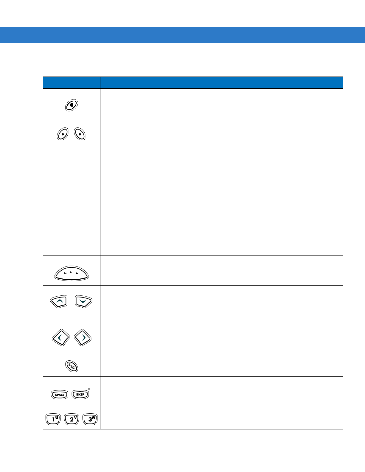
2 - 28 MC909X Mobile Computer User Guide
Table 2-9
Power (red) Turns the mobile computer on and off.
Green/Red Dot
43-Key Keypad Descriptions
Key Description
Performs a warm boot and a cold boot. See
information about performing a warm and cold boot.
MC9094 and MC9097:
Green dot: press to display the phone keypad window or to dial a phone number (from the
phone keypad window).
Red dot: press on phone keypad window to stop dialing or end a call.
MC9090:
To use a key as an application key (APP key) on the keyboard, a new keyboard remap table
must be created and installed. However, the Green/Red dot keys can be remapped as APP
keys through the registry.
Create an XML Provisioning file with the following entries:
Characteristic type =“HKEY_LOCAL_MACHINE\HARDWARE\DEVICEMAP\KEYBD”
Parm name = “GreenKeyOverride” value = “xx”, where xx is the new APP key code.
Parm name = “RedKeyOverride” value = “xx”, where xx is the new APP key code.
Refer to the MC909X Integrator Guide for instruction on updating the registry using XML
Provisioning.
This sends an APP key code, instead of their original key codes, when the green or red dot
key is pressed.
Windows Mobile 5.0 Devices on page 2-50
for
Scan (yellow) Activates the scanner/imager in a scan enabled application.
Scroll Up and Down Moves up and down from one item to another.
Increases/decreases specified values.
Scroll Left and
Right
ESC Exits the current operation.
SPACE/BKSP Space and backspace functions.
Numeric/Alpha Number or alpha value depending on the state of the ALPHA key.
Moves left and right from one item to another.
Increases/decreases specified values.
Page 73

Getting Started 2 - 29
LED
LED
ALT
Table 2-9
43-Key Keypad Descriptions (Continued)
Key Description
Alpha/Application These keys can have an application assigned to the function value and have an alpha value
assigned when used with the ALPHA function key.
On Windows Mobile 5.0 devices: F6
and F7 keys cannot be remapped and are dedicated
by the Operating System to control volume level. When these keys are pressed, Shell.exe
traps them and displays the volume adjustment window. To get these keys to an application,
call GXOpenInput() at the beginning of the application and call GXCloseInput() at the end of
the application. This redirects all of the key events to an application, including the
F6
and F7
keys.
Note:
Other applications cannot receive any key event until GXCloseInput() is called. For
example, if the customer is using the APP1 key to run Calc.exe, this is disabled during this
period.
Function (blue) Press and release the blue function key to activate the keypad alternate functions (shown on
the keypad in blue). The LED above the key lights and the icon appears at the bottom of
the screen. Press and release the blue function key again to return to the normal keypad
functions.
Control Press and release the CTRL key to activate the keypad alternate CTRL functions. The LED
above the key lights and the icon appears on the taskbar on WinCE devices or the
icon appears at the bottom of the screen on Windows Mobile 5.0 devices.
Press the Blue key followed by the CTRL key to activate the keypad alternate ALT functions.
The icon appears on the taskbar on WinCE devices or the icon appears at the
bottom of the screen on Windows Mobile 5.0 devices.
ALPHA (orange) The default keypad mode is the num-lock (number lock) mode. Press the orange
to de-activate the num-lock mode and to access the alternate
ALPHA
characters (shown on
the keypad in orange). The LED above the key lights and the icon appears on the
taskbar on WinCE devices or the icon appears at the bottom of the screen on Windows
Mobile 5.0 devices. Press and release the ALPHA key again to return to the normal keypad
functions.
Shift
Press and release the
SHIFT
key to activate the keypad alternate SHIFT functions. The
icon appears on the taskbar on WinCE devices or the icon appears at the bottom of the
screen on Windows Mobile 5.0 devices. Press and release the SHIFT key again to return to
the normal keypad functions.
Use with the orange alpha-lock key for alpha character value.
ALPHA
key
Page 74

2 - 30 MC909X Mobile Computer User Guide
Table 2-9
Period/Decimal
Point
Star Produces an asterisk and the alphabetic character Z when the ALPHA function key is
Enter Executes a selected item or function.
43-Key Keypad Descriptions (Continued)
Key Description
Produces a period for alpha entries, a decimal point for numeric entries and the alphabetic
character X when the ALPHA function key is activated.
activated.
For Windows Mobile 5.0:
The default behavior of the ENT (Enter) key sends an extra character, which causes a
Microsoft Word or Notes application to exit. To make the applications work properly, create an
XML Provisioning file with the following entries:
Characteristic type =”HKEY_LOCAL_MACHINE\HARDWARE\DEVICEMAP\KEYBD”
Para name = “SpecialEnterTabKey” value = 0
Refer to the MC909X Integrator Guide for instruction on updating the registry using XML
Provisioning.
Page 75

Getting Started 2 - 31
53-Key Keypad for MC909X-G/K
There are two physical configurations of the 53-key keypad, however both of the keypads are functionally identical.
The 53-key keypad contains a Power button, application keys, scroll keys and function keys. The keypad is
color-coded to indicate the alternate function key (blue) values. Note that keypad functions can be changed by an
application so the mobile computer’s keypad may not function exactly as described. See Table 2-10 on page 2-32
for key and button descriptions and Table 2-14 on page 2-43 for the keypad’s special functions.
Figure 2-22
53-Key Keypad for MC909X-G/K
Page 76

2 - 32 MC909X Mobile Computer User Guide
Table 2-10
Power (red) Turns the mobile computer on and off.
Green/Red Dot MC9094 and MC9097:
53-Key Descriptions
Key Description
Performs a warm boot and a cold boot. See
for information about performing a warm and cold boot.
Green dot: press to display the phone keypad window or to dial a phone number (from
the phone keypad window).
Red dot: press on phone keypad window to stop dialing or end a call.
MC9090:
To use a key as an application key (APP key) on the keyboard, a new keyboard remap
table must be created and installed. However, the Green/Red dot keys can be remapped
as APP keys through the registry.
Create an XML Provisioning file with the following entries:
Characteristic type =“HKEY_LOCAL_MACHINE\HARDWARE\DEVICEMAP\KEYBD”
Parm name = “GreenKeyOverride” value = “xx”, where xx is the new APP key code.
Parm name = “RedKeyOverride” value = “xx”, where xx is the new APP key code.
Refer to the MC909X Integrator Guide for instruction on updating the registry using XML
Provisioning.
This sends an APP key code, instead of their original key codes, when the green or red
dot key is pressed.
Windows Mobile 5.0 Devices on page 2-50
Scan (yellow) Activates the scanner/imager in a scan enabled application.
Scroll Up and Down Moves up and down from one item to another.
Increases/decreases specified values.
Scroll Left and Right Moves left and right from one item to another.
Increases/decreases specified values.
ESC Exits the current operation.
Alpha Use the alpha keys for alphabetic characters.
SPACE/BKSP Space and backspace functions.
Page 77

Getting Started 2 - 33
LED
LED
ALT
Table 2-10
53-Key Descriptions (Continued)
Key Description
Numeric/Application Numeric value keys - can have applications assigned with function key(s).
For Windows Mobile 5.0 devices: F6
and F7 keys cannot be remapped and are
dedicated by the Operating System to control volume level. When these keys are
pressed, Shell.exe traps them and displays the volume adjustment window. To get these
keys to an application, call GXOpenInput() at the beginning of the application and call
GXCloseInput() at the end of the application. This redirects all of the key events to an
application, including the
Note:
Other applications cannot receive any key event until GXCloseInput() is called. For
F6
and F7 keys.
example, if the customer is using the APP1 key to run Calc.exe, this is disabled during
this period.
Function (blue) Press and release the blue function key to activate the keypad alternate functions (shown
on the keypad in blue). The LED above the key lights and the icon appears on the
taskbar on WinCE devices or the icon appears at the bottom of the screen on
Windows Mobile 5.0 devices. Press and release the blue function key again to return to
the normal keypad functions.
Control Press and release the CTRL key to activate the keypad alternate CTRL functions. The
LED above the key lights and the icon appears on the taskbar on WinCE devices or
the icon appears at the bottom of the screen on Windows Mobile 5.0 devices.
Press the Blue key followed by the CTRL key to activate the keypad alternate ALT
functions. The icon appears on the taskbar on WinCE devices or the icon
appears at the bottom of the screen on Windows Mobile 5.0 devices.
Shift Press and release the SHIFT key to activate the keypad alternate SHIFT functions. The
icon appears on the taskbar on WinCE devices or the icon appears at the
bottom of the screen on Windows Mobile 5.0 devices. Press and release the SHIFT key
again to return to the normal keypad functions.
Period/Decimal Point Produces a period for alpha entries and a decimal point for numeric entries.
Star Produces an asterisk.
Enter Executes a selected item or function.
For Windows Mobile 5.0 devices:
The default behavior of the ENT (Enter) key sends an extra character, which causes a
Microsoft Word or Notes application to exit. To make the applications work properly,
create an XML Provisioning file with the following entries:
Characteristic type =”HKEY_LOCAL_MACHINE\HARDWARE\DEVICEMAP\KEYBD”
Para name = “SpecialEnterTabKey” value = 0
Refer to the MC909X Integrator Guide for instruction on updating the registry using XML
Provisioning.
Page 78

2 - 34 MC909X Mobile Computer User Guide
3270 Emulator Keypad for MC909X-G/K
There are two physical configurations of the 3270 emulator keypad, however both of the keypads are functionally
identical. The 3270 emulator keypad contains a Power button, application keys, scroll keys and a function key. The
keypad is color-coded to indicate the alternate function key (blue) values. Note that keypad functions can be
changed by an application so the mobile computer’s keypad may not function exactly as described. See Table 2-11
on page 2-35 for key and button descriptions and Table 2-14 on page 2-43 for the keypad’s special functions.
Figure 2-23
NOTE The 3270 emulator keypad is only used when the mobile computer is running the 3270 emulation
3270 Emulator Keypad for MC909X-G/K
software. When the mobile computer is not running the 3270 emulation software, the 3270 keypad
functions are the same as a 53-key keypad.
Page 79

Getting Started 2 - 35
Table 2-11
Power (red) Turns the mobile computer on and off.
Green/Red Dot To use a key as an application key (APP key) on the keyboard, a new keyboard remap
Scan (yellow) Activates the scanner/imager in a scan enabled application.
3270 Emulator Descriptions
Key Description
Performs a warm boot and a cold boot. See
2-50
for information about performing a warm and cold boot.
table must be created and installed. However, the Green/Red dot keys can be
remapped as APP keys through the registry.
Create an XML Provisioning file with the following entries:
Characteristic type =“HKEY_LOCAL_MACHINE\HARDWARE\DEVICEMAP\KEYBD”
Parm name = “GreenKeyOverride” value = “xx”, where xx is the new APP key code.
Parm name = “RedKeyOverride” value = “xx”, where xx is the new APP key code.
Refer to the MC909X Integrator Guide for instruction on updating the registry using
XML Provisioning.
This sends an APP key code, instead of their original key codes, when the green or red
dot key is pressed.
Windows Mobile 5.0 Devices on page
Scroll Up and Down Moves up and down from one item to another.
Increases/decreases specified values.
Scroll Left and Right Moves left and right from one item to another.
Increases/decreases specified values.
CLR Exits the current operation.
Alpha Use the alpha keys for alphabetic characters.
SPACE/BKSP Space and backspace functions.
Page 80

2 - 36 MC909X Mobile Computer User Guide
LED
LED
ALT
ALT
Table 2-11
3270 Emulator Descriptions (Continued)
Key Description
Application These keys can be assigned to an application.
On Windows Mobile 5.0 devices: F6
and F7 keys cannot be remapped and are
dedicated by the Operating System to control volume level. When these keys are
pressed, Shell.exe traps them and displays the volume adjustment window. To get
these keys to an application, call GXOpenInput() at the beginning of the application and
call GXCloseInput() at the end of the application. This redirects all of the key events to
an application, including the
Note:
Other applications cannot receive any key event until GXCloseInput() is called.
F6
and F7 keys.
For example, if the customer is using the APP1 key to run Calc.exe, this is disabled
during this period.
Function (blue) Press and release the blue function key to activate the keypad alternate functions
(shown on the keypad in blue). The LED above the key lights and the icon appears
on the taskbar on WinCE devices or the icon appears at the bottom of the screen
on Windows Mobile 5.0 devices. Press and release the blue function key again to return
to the normal keypad functions.
Control Press and release the CTRL key to activate the keypad alternate CTRL functions. The
LED above the key lights and the icon appears on the taskbar on WinCE devices or
the icon appears at the bottom of the screen on Windows Mobile 5.0 devices.
Press the Blue key followed by the CTRL key to activate the keypad alternate ALT
functions. The icon appears on the taskbar on WinCE devices or the icon
appears at the bottom of the screen on Windows Mobile 5.0 devices.
Shift Press and release the SHIFT key to activate the keypad alternate SHIFT functions. The
icon appears on the taskbar on WinCE devices or the icon appears at the
bottom of the screen on Windows Mobile 5.0 devices. Press and release the SHIFT key
again to return to the normal keypad functions.
Period/Decimal Point Produces a period for alpha entries and a decimal point for numeric entries.
Star Produces an asterisk.
Enter Executes a selected item or function.
For Windows Mobile 5.0:
The default behavior of the ENT (Enter) key sends an extra character, which causes a
Microsoft Word or Notes application to exit. To make the applications work properly,
create an XML Provisioning file with the following entries:
Characteristic type =”HKEY_LOCAL_MACHINE\HARDWARE\DEVICEMAP\KEYBD”
Para name = “SpecialEnterTabKey” value = 0
Refer to the MC909X Integrator Guide for instruction on updating the registry using
XML Provisioning.
Page 81

Getting Started 2 - 37
5250 Emulator Keypad for MC909X-G/K
There are two physical configurations of the 5250 emulator keypad, however both of the keypads are functionally
identical. The 5250 emulator keypad contains a Power button, application keys, scroll keys and a function key. The
keypad is color-coded to indicate the alternate function key (blue) values. Note that keypad functions can be
changed by an application so the mobile computer’s keypad may not function exactly as described. See Table 2-12
on page 2-38 for key and button descriptions and Table 2-14 on page 2-43 for the keypad’s special functions.
Figure 2-24
NOTE The 5250 emulator configuration is only used when the mobile computer is running the 5250 emulation
5250 Emulator Keypad for MC909X-G/K
software. When the mobile computer is not running the 5250 emulation software, the 5250 keypad functions
are the same as a 53-key keypad.
Page 82

2 - 38 MC909X Mobile Computer User Guide
Table 2-12
Power (red) Turns the mobile computer on and off.
Green/Red Dot
Scan (yellow) Activates the scanner/imager in a scan enabled application.
5250 Emulator Descriptions
Key Description
Performs a warm boot and a cold boot. See
2-50
for information about performing a warm and cold boot.
To use a key as an application key (APP key) on the keyboard, a new keyboard remap
table must be created and installed. However, the Green/Red dot keys can be
remapped as APP keys through the registry.
Create an XML Provisioning file with the following entries:
Characteristic type =“HKEY_LOCAL_MACHINE\HARDWARE\DEVICEMAP\KEYBD”
Parm name = “GreenKeyOverride” value = “xx”, where xx is the new APP key code.
Parm name = “RedKeyOverride” value = “xx”, where xx is the new APP key code.
Refer to the MC909X Integrator Guide for instruction on updating the registry using
XML Provisioning.
This sends an APP key code, instead of their original key codes, when the green or red
dot key is pressed.
Windows Mobile 5.0 Devices on page
Scroll Up and Down Moves up and down from one item to another.
Scroll Left and Right Moves left and right from one item to another.
ENT Exits the current operation.
Alpha Use the alpha keys for alphabetic characters.
SPACE/BKSP Space and backspace functions.
Page 83

Getting Started 2 - 39
LED
LED
ALT
ALT
Table 2-12
5250 Emulator Descriptions (Continued)
Key Description
Application These keys can be assigned to an application.
On Windows Mobile 5.0 devices: F6
and F7 keys cannot be remapped and are
dedicated by the Operating System to control volume level. When these keys are
pressed, Shell.exe traps them and displays the volume adjustment window. To get
these keys to an application, call GXOpenInput() at the beginning of the application and
call GXCloseInput() at the end of the application. This redirects all of the key events to
an application, including the
Note:
Other applications cannot receive any key event until GXCloseInput() is called.
F6
and F7 keys.
For example, if the customer is using the APP1 key to run Calc.exe, this is disabled
during this period.
Function (blue) Press and release the blue function key to activate the keypad alternate functions
(shown on the keypad in blue). The LED above the key lights and the icon appears
on the taskbar on WinCE devices or the icon appears at the bottom of the screen
on Windows Mobile 5.0 devices. Press and release the blue function key again to
return to the normal keypad functions.
Control Press and release the CTRL key to activate the keypad alternate CTRL functions. The
LED above the key lights and the icon appears on the taskbar on WinCE devices or
the icon appears at the bottom of the screen on Windows Mobile 5.0 devices.
Press the Blue key followed by the CTRL key to activate the keypad alternate ALT
functions. The icon appears on the taskbar on WinCE devices or the icon
appears at the bottom of the screen on Windows Mobile 5.0 devices.
Shift Press and release the SHIFT key to activate the keypad alternate SHIFT functions. The
icon appears on the taskbar on WinCE devices or the icon appears at the
bottom of the screen on Windows Mobile 5.0 devices. Press and release the SHIFT key
again to return to the normal keypad functions.
Period/Decimal Point Produces a period for alpha entries and a decimal point for numeric entries.
Star Produces an asterisk.
Enter Executes a selected item or function.
For Windows Mobile 5.0:
The default behavior of the Enter key sends an extra character, which causes a
Microsoft Word or Notes application to exit. To make the applications work properly,
create an XML Provisioning file with the following entries:
Characteristic type =”HKEY_LOCAL_MACHINE\HARDWARE\DEVICEMAP\KEYBD”
Para name = “SpecialEnterTabKey” value = 0
Refer to the MC909X Integrator Guide for instruction on updating the registry using
XML Provisioning.
Page 84

2 - 40 MC909X Mobile Computer User Guide
VT Emulator Keypad
The VT emulator keypad contains a Power button, application keys, scroll keys and a function key. The keypad is
color-coded to indicate the alternate function key (blue) values. Note that keypad functions can be changed by an
application so the mobile computer’s keypad may not function exactly as described. See Table 2-13 on page 2-41
for key and button descriptions and Table 2-14 on page 2-43 for the keypad’s special functions.
Figure 2-25
NOTE The VT emulator configuration is only used when the mobile computer is running the VT emulation software.
VT Emulator Keypad
When the mobile computer is not running the VT emulation software, the VT keypad functions are the same
as a 53-key keypad.
Page 85

Getting Started 2 - 41
Table 2-13
Power (red) Turns the mobile computer on and off.
Green/Red Dot
Scan (yellow) Activates the scanner/imager in a scan enabled application.
VT Emulator Descriptions
Key Description
Performs a warm boot and a cold boot. See
for information about performing a warm and cold boot.
To use a key as an application key (APP key) on the keyboard, a new keyboard remap
table must be created and installed. However, the Green/Red dot keys can be remapped
as APP keys through the registry.
Create an XML Provisioning file with the following entries:
Characteristic type =“HKEY_LOCAL_MACHINE\HARDWARE\DEVICEMAP\KEYBD”
Parm name = “GreenKeyOverride” value = “xx”, where xx is the new APP key code.
Parm name = “RedKeyOverride” value = “xx”, where xx is the new APP key code.
Refer to the MC909X Integrator Guide for instruction on updating the registry using XML
Provisioning.
This sends an APP key code, instead of their original key codes, when the green or red
dot key is pressed.
Windows Mobile 5.0 Devices on page 2-50
Scroll Up and Down Moves up and down from one item to another.
Scroll Left and Right Moves left and right from one item to another.
ESC Exits the current operation.
Alpha Use the alpha keys for alphabetic characters.
SPACE/BKSP Space and backspace functions.
Page 86

2 - 42 MC909X Mobile Computer User Guide
LED
LED
ALT
Table 2-13
VT Emulator Descriptions (Continued)
Key Description
Application These keys can be assigned to an application.
F6
and F7 keys cannot be remapped and are dedicated by the Operating System to
control volume level. When these keys are pressed, Shell.exe traps them and displays the
volume adjustment window. To get these keys to an application, call GXOpenInput() at the
beginning of the application and call GXCloseInput() at the end of the application. This
redirects all of the key events to an application, including the
Note:
Other applications cannot receive any key event until GXCloseInput() is called. For
F6
and F7 keys.
example, if the customer is using the APP1 key to run Calc.exe, this is disabled during
this period.
Function (blue) Press and release the blue function key to activate the keypad alternate functions (shown
on the keypad in blue). The LED above the key lights and the icon appears on the
taskbar on WinCE devices or the icon appears at the bottom of the screen on
Windows Mobile 5.0 devices. Press and release the blue function key again to return to
the normal keypad functions.
Control Press and release the CTRL key to activate the keypad alternate CTRL functions. The
LED above the key lights and the icon appears on the taskbar on WinCE devices or
the icon appears at the bottom of the screen on Windows Mobile 5.0 devices.
Press the Blue key followed by the CTRL key to activate the keypad alternate ALT
functions. The icon appears on the taskbar on WinCE devices or the icon
appears at the bottom of the screen on Windows Mobile 5.0 devices.
Shift Press and release the SHIFT key to activate the keypad alternate SHIFT functions. The
icon appears on the taskbar on WinCE devices or the icon appears at the bottom
of the screen on Windows Mobile 5.0 devices. Press and release the SHIFT key again to
return to the normal keypad functions.
Period/Decimal Point Produces a period for alpha entries and decimal point for numeric entries.
Star Produces an asterisk.
Enter Executes a selected item or function.
For Windows Mobile 5.0:
The default behavior of the RETURN key sends an extra character, which causes a
Microsoft Word or Notes application to exit. To make the applications work properly,
create an XML Provisioning file with the following entries:
Characteristic type =”HKEY_LOCAL_MACHINE\HARDWARE\DEVICEMAP\KEYBD”
Para name = “SpecialEnterTabKey” value = 0
Refer to the MC909X Integrator Guide for instruction on updating the registry using XML
Provisioning.
Page 87

Getting Started 2 - 43
Keypad Special Functions
The keypad special functions are color coded on the keypads. For example, on the 53-key keypad, the display
backlight icon is blue indicating that the blue function key must be selected first to access the display backlight. On
the 43-key keypad, the display backlight icon is white indicating that the display backlight is the default value for
that key.
Table 2-14
Icon
Keypad Special Functions
28-Key
Keypad
Blue key
+
#
Blue key
+
0
Blue key
+
1
Blue key
+
4
33-Key
Keypad
Blue key
+
7
Blue key
+
4
Blue key
+
8
Blue key
+
5
38-Key
Alpha/Shifte
d Numeric
Keypad
Blue key +
Blue key +
Blue key +
Blue key +
38-Key
Numeric/
Function
Keypad
V
Y
A
Blue key + F1Blue key + F1Blue key + DMonochrome units:
E
Blue key + F5Blue key + F5Blue key + IMonochrome units:
key
key
43-Key
Keypad
key
key
53-Key,
3270,
5250, VT
Keypad
Blue key +
Z
Blue key +
X
Special Function
Turns on and off the
display backlight.
Turns on and off the
keypad backlight.
Increases display
contrast.
Color units: Increases
display backlight
intensity.
Decreases display
contrast.
Color units: Increases
display backlight
intensity.
Blue key
+
3
Blue key
+
6
Blue key
+
CTRL
Not
available
NOTE Use of display and keypad backlighting can significantly reduce battery life. Mobile computers with color
Blue key
+
9
Blue key
+
6
Blue key
+
CTRL
Not
available
screens do not have contrast settings.
Blue key +
Blue key +
Blue key +
Blue key +
D
H
X
U
Blue key + F4Blue key + F4Blue key + HIncreases scan
decode beeper
volume.
Blue key + F8Blue key + F8Blue key + MDecreases scan
decode beeper
volume.
Blue key +
CTRL
Not
available
Blue key +
CTRL
Not
available
Blue key +
CTRL
Not
available
Enables Alt keypad
functions.
Sends TAB character
(forward tab).
Page 88

2 - 44 MC909X Mobile Computer User Guide
Single-hand Method
Two-hand Method
Entering Data
When entering data on the keypad, use either the single-hand method or the two-hand method as shown in Figure
2-26.
Figure 2-26
Entering Data on the Keypad
Using the Power Button
Press the red Power button to turn the mobile computer screen on and off (suspend mode). The mobile computer
is on when the screen is on and the mobile computer is in suspend mode when the screen is off. For more
information, see Starting the Mobile Computer on page 1-10.
The Power button is also used to reset the mobile computer by performing a warm or cold boot.
•
On Windows CE 5.0
• Warm Boot (Soft Reset) - Resets the mobile computer.
• Cold Boot (Hard Reset) - Resets the mobile computer, removes all added applications and restores all
factory default settings.
Page 89

•
On Windows Mobile 5.0
• Warm Boot (Soft Reset) - Resets the mobile computer. Operating system and all applications are
restarted. File storage is preserved.
• Cold Boot (Hard Reset) - Resets the mobile computer Operating system and all applications are restarted.
File storage is preserved. Real-Time Clock (RTC) is reset. Normally only used when a Warm Boot does
not initiate.
NOTE Applications that are added to the Application folder are not removed when a cold boot is performed. The
Application folder is in flash memory.
For information about booting the mobile computer, see Windows Mobile 5.0 Devices on page 2-50.
Using a Wired Headset
You can use a stereo headset for audio communication when an audio enabled application is used. To use a
headset, plug the headset jack into the audio connector on the side of the mobile computer. Ensure that the mobile
computer’s volume is set appropriately before putting the headset on. When a headset is plugged into the jack, the
speakerphone is muted.
Getting Started 2 - 45
For WWAN-enabled mobile computers, Zebra recommends a 2.5mm jack headset, p/n 50-11300-050.
NOTE The MC9094 and MC9097 does not support headsets with buttons used to answer or hang-up a call. Use the
green dot or red dot keys on the keypad.
Figure 2-27
Using a Headset (MC9090-G Shown)
Page 90

2 - 46 MC909X Mobile Computer User Guide
Using a Bluetooth Headset
You can use a Bluetooth headset for audio communication when an audio enabled application is used. See
Chapter 3, Using Bluetooth for information on connecting a Bluetooth device to the mobile computer. Ensure that
the mobile computer’s volume is set appropriately before putting the headset on. When a Bluetooth headset is
connected the speakerphone is muted.
NOTE The MC9094 and MC9097 does not support headsets with buttons used to answer or hang-up a call. Use the
green dot or red dot keys on the keypad.
If the mobile computer goes into suspend mode the Bluetooth connection is disabled and the mobile
computer automatically switches to speakerphone mode.
Data Capture
Mobile computers with an integrated laser scanner allow you to collect data by scanning one dimensional bar
codes.
Mobile computers with an integrated imager allow you to collect data by decoding one dimensional bar codes
(including RSS) and two dimensional bar codes (including PDF417 and DataMatrix), and capture and download
images to a host for a variety of imaging applications.
Laser Scanning
Mobile computers with an integrated laser scanner have the following features:
•
Reading of a variety of bar code symbologies, including the most popular linear, postal, and 1-D code types.
•
Advanced intuitive laser aiming for easy point-and-shoot operation.
Imaging
Mobile computers with an integrated imager have the following features:
•
Omnidirectional reading of a variety of bar code symbologies, including the most popular linear, postal,
PDF417 and 2-D matrix code types.
•
The ability to capture and download images to a host for a variety of imaging applications.
•
Advanced intuitive laser aiming for easy point-and-shoot operation.
The imager uses digital camera technology to take a digital picture of a bar code, stores the resulting image in its
memory and executes state-of-the-art software decoding algorithms to extract the data from the image.
Aiming the Imager
The mobile computer’s integrated imager projects a laser aiming pattern (field of view) similar to those used on
cameras. The aiming pattern is used to position the bar code or object within the field of view.
Page 91

Getting Started 2 - 47
Figure 2-28
Laser Aiming Pattern (Field of View)
Operational Modes
Mobile computers with an integrated imager have three modes of operation: Decode Mode, Pick List Mode and
Image Capture Mode. All modes are activated by pulling the trigger or pressing the Scan button.
Decode Mode
This mode allows the user to decode a bar code when a single bar code in the mobile computer’s field of view. In
this mode the Imager attempts to locate and decode enabled bar codes within its field of view. The Imager remains
in this mode as long as the trigger is pulled, or until a bar code is decoded.
Pick List Mode
Pick List mode allows the user to selectively decode a bar code when more than one bar code is in the mobile
computer’s field of view. By moving the aiming crosshair over the wanted bar code the user can selectively read
only the required bar code. This feature is particularly valued for pick lists containing multiple bar codes and
manufacturing or transport labels containing more than one bar code type (either 1D or 2D).
Image Capture Mode
This mode allows the user to capture an image within the mobile computer’s field of view. The user can use the
mobile computer to capture signatures or images of items like damaged boxes.
Scanning Considerations
Typically, scanning is a simple matter of aim, scan/decode and a few quick trial efforts master it. However, two
important considerations can be used to optimize any scanning performance:
•
Range
Any scanning device decodes well over a particular working range — minimum and maximum distances from
the bar code. This range varies according to bar code density and scanning device optics.
Scanning within range brings quick and constant decodes; scanning too close or too far away prevents
decodes. Move the scanner closer and further away to find the right working range for the bar codes being
scanned. However, the situation is complicated by the availability of various integrated scanning modules. The
best way to specify the appropriate working range per bar code density is through a chart called a decode zone
for each scan module. A decode zone simply plots working range as a function of minimum element widths of
bar code symbols.
•
Angle
Scanning angle is important for promoting quick decodes. When laser beams reflect directly back into the
scanner from the bar code, this specular reflection can “blind” the scanner.
To avoid this, scan the bar code so that the beam does not bounce directly back. But don’t scan at too sharp an
angle; the scanner needs to collect scattered reflections from the scan to make a successful decode. Practice
quickly shows what tolerances to work within.
NOTE Contact the Zebra Support Center if chronic scanning difficulties develop. Decoding of properly printed bar
codes should be quick and effortless.
Page 92

2 - 48 MC909X Mobile Computer User Guide
Scanning Bar Codes
1. Ensure that a scan enabled application is loaded on the mobile computer.
2. Aim the scan exit window at the bar code.
3. Pull the trigger.
•
For mobile computers with a laser scanner, ensure the red scan beam covers the entire bar code. The red
scan LED lights to indicate that the laser is on. The green scan LED lights and an audible beep sounds, by
default, to indicate the bar code was decoded successfully.
Figure 2-29
•
For mobile computers with an imager, place the bar code in any orientation within the aiming pattern.
Ensure the entire symbol is within the rectangular area formed by the brackets in the aiming pattern. The
red laser aiming pattern turns on to assist in aiming. If necessary, the mobile computer turns on its red LED
to illuminate the target bar code. The green scan LED lights and an audible beep sounds, by default, to
indicate the bar code was decoded successfully. Note that when the mobile computer is in Pick List Mode,
the bar code is not decoded until the crosshair is touching the bar code.
Linear bar code
Figure 2-30
Laser Scanner Aiming Pattern
PDF417 symbol
Symbol
View Finder
(Aiming Pattern)
Bar Code Centered in Aiming Pattern
Figure 2-31
Figure 2-32
Bar Code Not Centered in Aiming Pattern
Pick List Mode with Multiple Bar Codes in Aiming Pattern
Page 93

4. Release the trigger.
NOTE Imager decoding usually occurs instantaneously. The mobile computer repeats the steps required to take a
digital picture (image) of a poor or difficult bar code, as long as the trigger remains pulled.
Scanning Tips
Optimal scanning distance varies with bar code density and scanner optics.
•
Hold the scanner farther away for larger symbols.
•
Move the scanner closer for symbols with bars that are close together.
NOTE Scanning procedures depend on the application and mobile computer configuration. An application may use
different scanning procedures from the one listed above.
Scan LED Indicator
The Indicator LED bar on the mobile computer provides a visual indication of the scan status.
Getting Started 2 - 49
Table 2-15
Off Not scanning.
Solid Red Laser enabled, scanning/imaging in process.
Solid Green Successful decode.
Scan LED Indicators
LED Status Indication
Resetting the Mobile Computer
Windows CE 5.0 Devices
There are two reset functions, warm boot and cold boot. A warm boot restarts the mobile computer by closing all
running programs.
A cold boot also restarts the mobile computer, but erases all stored records and entries in RAM. Data saved in flash
memory or a memory card is not lost. In addition it returns formats, preferences and other settings to the factory
default settings.
Perform a warm boot first. This restarts the mobile computer and saves all stored records and entries. If the mobile
computer still does not respond, perform a cold boot.
Performing a Warm Boot
Hold down the Power button for approximately five seconds. As soon as the mobile computer starts to perform a
warm boot release the Power button.
Page 94

2 - 50 MC909X Mobile Computer User Guide
Performing a Cold Boot
A cold boot restarts the mobile computer and erases all user stored records and entries that are not saved in flash
memory (Application and Platform folders) or a memory card. Never perform a cold boot unless a warm boot does
not solve the problem.
CAUTION Do not hold down any key, other than the Power button during a reset. Performing a cold boot restores
formats, preferences and other settings to the default settings.
NOTE Any data previously synchronized with a computer can be restored during the next ActiveSync operation.
To perform a cold boot:
1. Press the primary battery release on the mobile computer to partially eject the battery from the mobile
computer.
2. While the battery is partially released, simultaneously press and release the handle trigger and the Power
button.
3. Push the battery to fully re-insert it in the mobile computer. One audible click can be heard as the battery is fully
inserted.
4. The mobile computer initializes.
5. Calibrate the screen. See Calibrating the Screen on page 1-10 to calibrate the mobile computer screen.
Windows Mobile 5.0 Devices
There are two reset functions, warm boot and cold boot.
•
A warm boot restarts the mobile computer and closes all running programs.
•
A cold boot also restarts the mobile computer and closes all running programs but also resets the
Real-Time-Clock (RTC).
Data saved in flash memory or a memory card is not lost. Perform a warm boot first. This restarts the mobile
computer and saves all stored records and entries. If the mobile computer still does not respond, perform a cold
boot.
Performing a Warm Boot
Hold down the Power button for approximately five seconds. As soon as the mobile computer starts to perform a
warm boot release the Power button.
Performing a Cold Boot
A cold boot restarts the mobile computer. The operating system and all applications are restarted. File storage is
preserved. The Real-Time-Clock (RTC) resets. Only perform a cold boot if a warm boot does not solve the
problem.
To perform a cold boot:
1. Press the primary battery release on the mobile computer to partially eject the battery from the mobile
computer.
Page 95

Getting Started 2 - 51
2. On an MC9090-G, while the battery is partially released, simultaneously press and release the trigger and the
Power button.
3. On an MC-909X-K or MC909X-S, while the battery is partially released, simultaneously press and release the
left scan button and the Power button.
4. Push the battery to fully re-insert it in the mobile computer. One audible click can be heard as the battery is fully
inserted.
5. The mobile computer initializes.
Waking the Mobile Computer
The wakeup conditions define what actions wakeup the mobile computer. These settings are configurable and the
factory default settings shown in Table 2-16 are subject to change/update.
Table 2-16
Power Off When the mobile computer is set to the suspend
Auto Off When the mobile computer goes into suspend mode
Wakeup Conditions (Default Settings)
Status Description Conditions for Wakeup
Power
button is pressed.
Power
button is pressed.
mode by pressing
mobile computer.
by an automatic power-off function, these actions
wake the mobile computer.
Power
, these actions wake the
1.
2. AC power added or removed.
3. Cradle/cable connect or disconnect.
Key or scan button is pressed.
Real Time Clock set to wake up.
Incoming phone call (MC9094 and MC9097
only)
1.
2. AC power added or removed.
3. Cradle/cable connect or disconnect.
Key or scan button is pressed.
Real Time Clock set to wake up.
Incoming phone call (MC9094 and MC9097
only).
Page 96

2 - 52 MC909X Mobile Computer User Guide
Page 97

Chapter 3 Using Bluetooth
Introduction
Bluetooth-equipped devices can communicate without wires, using frequency-hopping spread spectrum (FHSS)
RF to transmit and receive data in the 2.4 GHz Industry Scientific and Medical (ISM) band (802.15.1). Bluetooth
wireless technology is specifically designed for short-range (30 feet/10 meters) communications and low power
consumption.
Mobile computers with Bluetooth capabilities can exchange information (e.g., files, appointments and tasks) with
other Bluetooth enabled devices such as phones, printers, access points and other mobile computers. In addition,
a dial-up modem connection can be created between the Bluetooth mobile computer and a Bluetooth enabled
phone. The Bluetooth phone can then be used as a modem.
Zebra mobile computers with Bluetooth technology use the StoneStreet One Bluetooth stack. To program
Bluetooth within the mobile computer refer to the StoneStreet One SDK.
Adaptive Frequency Hopping
Adaptive Frequency Hopping (AFH) is a method of avoiding fixed frequency interferers. AFH can be used with
Bluetooth voice. All devices in the piconet (Bluetooth network) must be AFH-capable in order for AFH to work.
There is no AFH when connecting and discovering devices. Avoid making Bluetooth connections and discoveries
during critical 802.11b communications. AFH for Bluetooth can be broken-down into four main sections:
•
Channel Classification - A method of detecting an interference on a channel-by-channel basis, or pre-defined
channel mask.
•
Link Management - Coordinates and distributes the AFH information to the rest of the Bluetooth network.
•
Hop Sequence Modification - Avoids the interference by selectively reducing the number of hopping
channels.
•
Channel Maintenance - A method for periodically re-evaluating the channels.
When AFH is enabled, the Bluetooth radio “hops-around” (instead of through) the 802.11b high-rate channels. AFH
coexistence allows Zebra mobile computers to operate in any infrastructure. AFH is always enabled in the
MC909X.
Page 98

3 - 2 MC909X Mobile Computer User Guide
The Bluetooth radio in this mobile computer operates as a Class 2 device power class. The maximum output power
is 2.5mW and the expected range is up to 32.8 feet (10 meters). A definitive definition of ranges based on power
class is difficult to obtain due to power and device differences, and whether one measures open space or closed
office space.
NOTE It is not recommended to perform Bluetooth wireless technology inquiry when high rate 802.11b operation
is required.
Security
The current Bluetooth specification defines security at the link level. Application-level security is not specified. This
allows application developers to define security mechanisms tailored to their specific need. Link-level security is
really between devices not users, while application-level security can be implemented on a per-user basis. The
Bluetooth specification defines security algorithms and procedures needed to authenticate devices, and if needed,
encrypt the data flowing on the link between the devices. Device authentication is a mandatory feature of Bluetooth
while link encryption is optional.
Pairing of Bluetooth devices is accomplished by creating an initialization key that is used to authenticate the
devices and create a link key for them. Entering a common PIN number in the devices being paired generates the
initialization key. The PIN number is never sent over the air. By default, the Bluetooth stack responds with no key
when a key is requested (it is up to user to respond to the key request event). Authentication of Bluetooth devices
is based-upon a challenge-response transaction. Bluetooth allows for a PIN number or passkey that is used to
create other 128-bit keys used for security and encryption. The encryption key is derived from the link key used to
authenticate the pairing devices. Also worthy of note is the limited range and fast frequency hopping of the
Bluetooth radios that makes long-distance eavesdropping difficult.
It is recommended:
•
Perform pairing in a secure environment
•
Keep PIN codes private and don't store the PIN codes in the mobile computer
•
Implement application-level security.
Turning the Bluetooth Radio Mode On and Off
Turn off the Bluetooth radio to save power or if entering an area with radio restrictions (e.g., an airplane). When the
radio is off, the mobile computer can not be seen or connected to by other Bluetooth devices. Turn on the Bluetooth
radio to exchange information with other Bluetooth devices (within range). Communicate only with Bluetooth radios
in close proximity.
NOTE To achieve the best battery life in mobile computers with multiple radios, turn off the radios that are not
being used.
Disabling Bluetooth
To disable Bluetooth, tap Bluetooth icon > Disable Bluetooth. The Bluetooth icon changes to indicate that Bluetooth
is disabled. An exclamation point appears with the icon.
Page 99

Using Bluetooth 3 - 3
Figure 3-1
Disable Bluetooth
Enabling Bluetooth
To enable Bluetooth, tap Bluetooth icon > Enable Bluetooth. The Bluetooth icon changes to indicate that Bluetooth
is enabled.
Figure 3-2
Enable Bluetooth
Bluetooth Power States
Cold Boot
When a cold boot is performed on the mobile computer, Bluetooth turns off. It is normal to see the Bluetooth icon
appear and disappear, as well as a wait cursor, when initialization proceeds in all modes.
Warm Boot
When a warm boot is performed on the mobile computer, Bluetooth returns to the disabled state (off).
Page 100

3 - 4 MC909X Mobile Computer User Guide
Suspend
When the mobile computer suspends, Bluetooth turns off.
NOTE When the mobile computer is placed in suspend mode, the Bluetooth radio mode powers off and the
piconet (Bluetooth connection) is dropped. When the mobile computer resumes, it could take up to 10
seconds for the Bluetooth radio driver to re-initialize the radio.
Resume
When the mobile computer resumes, Bluetooth turns on if it was on prior to suspend. Note that any Bluetooth
connection that was dropped during a suspend needs to be reconnected after a resume.
Bluetooth Profiles
The mobile computer is loaded with a number of Bluetooth services profiles. These profiles can be loaded or
removed from memory. If a profile is not used, it can be removed to save memory. To load or remove profiles:
NOTE On Windows CE 5.0 devices, BTExplorer must be disabled prior to changing profiles. Windows Mobile 5.0
devices do not require disabling BTExplorer.
1. On Windows CE 5.0 devices only, if BTExplorer is running, tap > Disable Bluetooth.
2. Tap > Programs > BTProfileSelctor. The ProfileSelector window appears.
Figure 3-3
3. Tap a check box next to the profile to load (activate).
Bluetooth Profile Selector Window
The Serial Port profile is always active and cannot be removed.
4. Ta p Select All to select all profiles or tap Deselect All to deselect all profiles.
5. Ta p Apply to activate the profiles and then Close to exit the application.
6. On Windows CE 5.0 devices only, tap > Enable Bluetooth to enable BTExplorer application.
See Services Tab on page 3-22 for more information on selecting services.
 Loading...