

Page 1

MC75 Enterprise Digital Assistant
User Guide
Page 2

Page 3

MC75 Enterprise Digital Assistant
User Guide
72E-103077-05
Rev. A
April 2015
Page 4

ii MC75 User Guide
© 2015 ZIH Corp
No part of this publication may be reproduced or used in any form, or by any electrical or mechanical means,
without permission in writing from Zebra. This includes electronic or mechanical means, such as photocopying,
recording, or information storage and retrieval systems. The material in this manual is subject to change
without notice.
The software is provided strictly on an “as is” basis. All software, including firmware, furnished to the user is on
a licensed basis. Zebra grants to the user a non-transferable and non-exclusive license to use each software
or firmware program delivered hereunder (licensed program). Except as noted below, such license may not be
assigned, sublicensed, or otherwise transferred by the user without prior written consent of Zebra. No right to
copy a licensed program in whole or in part is granted, except as permitted under copyright law. The user shall
not modify, merge, or incorporate any form or portion of a licensed program with other program material, create
a derivative work from a licensed program, or use a licensed program in a network without written permission
from Zebra. The user agrees to maintain Zebra’s copyright notice on the licensed programs delivered
hereunder, and to include the same on any authorized copies it makes, in whole or in part. The user agrees not
to decompile, disassemble, decode, or reverse engineer any licensed program delivered to the user or any
portion thereof.
Zebra reserves the right to make changes to any software or product to improve reliability, function, or design.
Zebra does not assume any product liability arising out of, or in connection with, the application or use of any
product, circuit, or application described herein.
No license is granted, either expressly or by implication, estoppel, or otherwise under any Zebra, intellectual
property rights. An implied license only exists for equipment, circuits, and subsystems contained in Zebra
products.
Page 5

Revision History
Changes to the original manual are listed below:
Change Date Description
-01 Rev. A 6/10/08 Initial release.
iii
-02 Rev. A 08/14/08 Add re-boot after installing SIM card. Add dual line
-03 Rev. A 03/09/10 Add OEM Version 02.35.000 and 02.35.001support. Add DSD keypad.
-04 Rev. A 10/22/10 Add OENM Version 03.38.xxx support.
-05 Rev. A 04/02/15 Zebra rebranding.
SIM support.
Page 6

iv MC75 User Guide
Page 7

Table of Contents
Revision History.................................................................................................................................... ii
About This Guide
Introduction ........................................................................................................................................... xiii
Documentation Set xiii
Configurations....................................................................................................................................... xiv
Software Versions xiv
Chapter Descriptions ............................................................................................................................ xvii
Notational Conventions......................................................................................................................... xvii
Related Documents .............................................................................................................................. xviii
Service Information............................................................................................................................... xviii
Chapter 1: Getting Started
Introduction .......................................................................................................................................... 1-1
Unpacking ............................................................................................................................................ 1-2
Getting Started ..................................................................................................................................... 1-4
Installing the SIM Card ................................................................................................................... 1-4
Installing the Main Battery .............................................................................................................. 1-6
Charging the Battery ...................................................................................................................... 1-7
Charging the Main Battery and Memory Backup Battery ......................................................... 1-7
Charging Spare Batteries ......................................................................................................... 1-8
Charging Temperature ............................................................................................................. 1-8
Powering On the MC75 .................................................................................................................. 1-8
Calibrating the Screen ................................................................................................................... 1-8
Checking Battery Status ................................................................................................................ 1-9
Micro Secure Digital (microSD) Card ................................................................................................... 1-9
Adjusting the Handstrap ...................................................................................................................... 1-10
Removing the Screen Protector ........................................................................................................... 1-10
Replacing the Main Battery .................................................................................................................. 1-11
Battery Management ........................................................................................................................... 1-12
Changing the Power Settings ........................................................................................................ 1-12
Changing the Backlight Settings .................................................................................................... 1-12
Changing the Keypad Backlight Settings ....................................................................................... 1-12
Page 8

vi MC75 User Guide
Turning Off the Radios ................................................................................................................... 1-13
Chapter 2: Using the MC75
Introduction .......................................................................................................................................... 2-1
Today Screen ...................................................................................................................................... 2-2
Status Icons ......................................................................................................................................... 2-2
Programs ............................................................................................................................................. 2-5
Settings ................................................................................................................................................ 2-8
Battery Status Indications .................................................................................................................... 2-11
Battery Reserve Options ................................................................................................................ 2-12
Main Battery Temperature Notifications ......................................................................................... 2-13
Performing a Warm Boot ............................................................................................................... 2-15
Performing a Cold Boot .................................................................................................................. 2-15
Waking the MC75 ................................................................................................................................ 2-15
Locking the MC75 ................................................................................................................................ 2-16
Numeric Keypad Configuration ...................................................................................................... 2-17
DSD Keypad Configuration ............................................................................................................ 2-21
Special Character Key ............................................................................................................. 2-30
Stylus ................................................................................................................................................... 2-32
Entering Data ....................................................................................................................................... 2-33
Linear Scanning ............................................................................................................................. 2-34
Imaging .......................................................................................................................................... 2-34
Operational Modes ................................................................................................................... 2-34
Digital Camera ............................................................................................................................... 2-35
Scanning Considerations ............................................................................................................... 2-35
Linear Scanning ............................................................................................................................. 2-35
Imager Scanning ............................................................................................................................ 2-36
Digital Camera Scanning ............................................................................................................... 2-37
Using the RS507 Hands-free Imager ............................................................................................. 2-38
Taking Photos ...................................................................................................................................... 2-39
Recording Video .................................................................................................................................. 2-39
Viewing Photos and Videos ................................................................................................................. 2-39
Infrared Connection ....................................................................................................................... 2-40
Exchanging Files using IR Connection .................................................................................... 2-40
Chapter 3: Using GPS Navigation
Introduction .......................................................................................................................................... 3-1
Software Installation ............................................................................................................................ 3-1
MC75 GPS Setup ................................................................................................................................ 3-1
Operation ............................................................................................................................................. 3-2
GPS Maps on microSD Cards ....................................................................................................... 3-2
Answering a Phone Call While Using GPS .................................................................................... 3-2
Losing the GPS Signal While in a Vehicle ..................................................................................... 3-2
Assisted GPS ....................................................................................................................................... 3-2
Chapter 4: Using Bluetooth
Introduction .......................................................................................................................................... 4-1
Page 9

Table of Contents vii
Adaptive Frequency Hopping .............................................................................................................. 4-1
Security ................................................................................................................................................ 4-2
Disabling Bluetooth ........................................................................................................................ 4-3
Enabling Bluetooth ......................................................................................................................... 4-3
Bluetooth Power States ................................................................................................................. 4-4
Cold Boot ................................................................................................................................. 4-4
Warm Boot ............................................................................................................................... 4-4
Suspend ................................................................................................................................... 4-4
Resume .................................................................................................................................... 4-4
Modes .................................................................................................................................................. 4-4
Wizard Mode .................................................................................................................................. 4-4
Explorer Mode ................................................................................................................................ 4-4
Available Services ............................................................................................................................... 4-9
File Transfer Services .................................................................................................................... 4-9
Creating a New File or Folder .................................................................................................. 4-10
Deleting a File .......................................................................................................................... 4-11
Getting a File ............................................................................................................................ 4-11
Copying a File .......................................................................................................................... 4-11
Connecting to the Internet Using an Access Point ......................................................................... 4-11
Dial-Up Networking Services ......................................................................................................... 4-12
Object Exchange Push Services .................................................................................................... 4-12
Sending a Contact ................................................................................................................... 4-13
Swapping Contacts .................................................................................................................. 4-14
Fetching a Contact ................................................................................................................... 4-15
Sending a Picture ..................................................................................................................... 4-15
Headset Services ........................................................................................................................... 4-16
Hands-free Services ...................................................................................................................... 4-17
Serial Port Services ....................................................................................................................... 4-18
ActiveSync Using Serial Port Services .......................................................................................... 4-18
Personal Area Network Services ................................................................................................... 4-20
IrMC Synchronization Services ...................................................................................................... 4-20
Bonding with Discovered Device(s) ..................................................................................................... 4-20
Deleting a Bonded Device ....................................................................................................... 4-22
Accepting a Bond ..................................................................................................................... 4-22
Bluetooth Settings ................................................................................................................................ 4-23
Device Info Tab .............................................................................................................................. 4-23
Services Tab .................................................................................................................................. 4-23
Dial-Up Networking Service ..................................................................................................... 4-24
File Transfer Service ................................................................................................................ 4-25
Hands-Free Audio Gateway Service ........................................................................................ 4-26
Headset Audio Gateway Service ............................................................................................. 4-26
IrMC Synchronization Service .................................................................................................. 4-26
OBEX Object Push Service ..................................................................................................... 4-27
Personal Area Networking Service .......................................................................................... 4-28
Serial Port Service ................................................................................................................... 4-29
Security Tab ................................................................................................................................... 4-29
Discovery Tab ................................................................................................................................ 4-30
Virtual COM Port Tab ..................................................................................................................... 4-31
HID Tab .......................................................................................................................................... 4-32
Profiles Tab .................................................................................................................................... 4-32
Page 10

viii MC75 User Guide
System Parameters Tab ................................................................................................................ 4-33
Miscellaneous Tab ......................................................................................................................... 4-33
Chapter 5: Using the Phone
Introduction .......................................................................................................................................... 5-1
Accessing the Phone Keypad .............................................................................................................. 5-1
Turning the Phone On and Off ............................................................................................................. 5-2
Using a Wired Headset .................................................................................................................. 5-3
Using a Bluetooth Headset ............................................................................................................ 5-4
Adjusting Audio Volume ................................................................................................................. 5-4
Making a Call ....................................................................................................................................... 5-5
Using the Phone ............................................................................................................................ 5-5
Using Contacts ............................................................................................................................... 5-5
Using Call History .......................................................................................................................... 5-6
Making a Speed Dial Call ............................................................................................................... 5-6
Making an Emergency Call .................................................................................................................. 5-7
Answering a Call .................................................................................................................................. 5-7
Incoming Call Features .................................................................................................................. 5-8
Smart Dialing ....................................................................................................................................... 5-8
Muting a Call ........................................................................................................................................ 5-9
Taking Notes ........................................................................................................................................ 5-10
Using Speed Dial ................................................................................................................................. 5-11
Adding a Speed Dial Entry ............................................................................................................. 5-11
Editing a Speed Dial Entry ............................................................................................................. 5-13
Deleting a Speed Dial Entry ........................................................................................................... 5-14
Using Call History ................................................................................................................................ 5-15
Managing Call History .................................................................................................................... 5-15
Changing the Call History View ............................................................................................... 5-15
Resetting the Recent Calls Counter ......................................................................................... 5-15
Deleting Call History Items by Call Date .................................................................................. 5-16
Deleting All Call History Items .................................................................................................. 5-17
Viewing Call Status .................................................................................................................. 5-18
Using the Call History Menu .................................................................................................... 5-18
Swapping Calls on an MC7506/96 ...................................................................................................... 5-19
Swapping Calls on an MC7508/98 ...................................................................................................... 5-20
Conference Calling on an MC7506/96 ................................................................................................. 5-20
Three-way Calling on an MC7508/98 .................................................................................................. 5-22
Text Messaging ................................................................................................................................... 5-23
Viewing Text Messages ................................................................................................................. 5-23
Sending a Text Message ............................................................................................................... 5-24
Using a Dual Line SIM ......................................................................................................................... 5-26
Chapter 6: Accessories
Introduction .......................................................................................................................................... 6-1
Single Slot USB/Serial Cradle ............................................................................................................. 6-2
Charging the MC75 Battery ........................................................................................................... 6-2
Charging the Spare Battery ........................................................................................................... 6-3
Battery Charging Indicators ........................................................................................................... 6-3
Page 11

Table of Contents ix
Charging Temperature ............................................................................................................. 6-3
Four Slot Ethernet Cradle .................................................................................................................... 6-4
Charging ........................................................................................................................................ 6-4
Battery Charging Indicators ........................................................................................................... 6-4
Charging Temperature ............................................................................................................. 6-4
Charging ........................................................................................................................................ 6-5
Battery Charging Indicators ........................................................................................................... 6-5
Charging Temperature ............................................................................................................. 6-5
Charging the MC75 Battery ........................................................................................................... 6-6
Removing the MC75 ................................................................................................................ 6-6
Charging the Spare Battery ........................................................................................................... 6-7
Battery Charging Indicators ........................................................................................................... 6-8
Charging Temperature ............................................................................................................. 6-8
MC75 Battery Shim Installation ...................................................................................................... 6-9
Spare Battery Charging ................................................................................................................. 6-9
Battery Charging Indicators ........................................................................................................... 6-10
Charging Temperature ............................................................................................................. 6-10
Attaching and Removing the MSR ................................................................................................. 6-11
Using the MSR ............................................................................................................................... 6-11
Getting Started ............................................................................................................................... 6-13
Installation ...................................................................................................................................... 6-13
Removal ............................................................................................................................................... 6-13
Credit Card Transactions ............................................................................................................... 6-14
Debit Card Transactions ................................................................................................................ 6-14
Keypad ........................................................................................................................................... 6-15
Display Messages .................................................................................................................... 6-16
Check the DCR Battery Level ........................................................................................................ 6-16
Installation ...................................................................................................................................... 6-18
Removal ............................................................................................................................................... 6-18
Credit Card Transactions ............................................................................................................... 6-19
Debit Card Transactions ................................................................................................................ 6-19
Chip and PIN Transactions ............................................................................................................ 6-20
Keypad ..................................................................................................................................... 6-20
Display Messages .......................................................................................................................... 6-21
Battery Charging and Operating Power ......................................................................................... 6-24
LED Charge Indications ................................................................................................................. 6-25
Charging Temperature ............................................................................................................. 6-25
Chapter 7: Maintenance & Troubleshooting
Introduction .......................................................................................................................................... 7-1
Maintaining the MC75 .......................................................................................................................... 7-1
Battery Safety Guidelines .................................................................................................................... 7-2
Cleaning ............................................................................................................................................... 7-3
Materials Required ......................................................................................................................... 7-3
Cleaning the MC75 ........................................................................................................................ 7-3
Housing .................................................................................................................................... 7-3
Display ..................................................................................................................................... 7-3
Scanner Exit Window ............................................................................................................... 7-3
Connector ................................................................................................................................ 7-3
Page 12

x MC75 User Guide
Cleaning Cradle Connectors .......................................................................................................... 7-4
Cleaning Frequency ....................................................................................................................... 7-4
Troubleshooting ................................................................................................................................... 7-5
MC75 ............................................................................................................................................. 7-5
Bluetooth Connection ..................................................................................................................... 7-7
Single Slot USB/Serial Cradle ........................................................................................................ 7-8
Four Slot Ethernet Cradle .............................................................................................................. 7-10
Vehicle Cradle ................................................................................................................................ 7-10
Four Slot Battery Charger .............................................................................................................. 7-11
Cables ............................................................................................................................................ 7-12
Magnetic Stripe Reader ................................................................................................................. 7-12
Appendix A: Technical Specifications
MC75 Technical Specifications ............................................................................................................ A-1
MC75 ............................................................................................................................................. A-1
Single Slot USB/Serial Cradle ........................................................................................................ A-6
Four Slot Ethernet Cradle .............................................................................................................. A-6
Four Slot Charge Only Cradle ........................................................................................................ A-7
Four Slot Battery Charger .............................................................................................................. A-7
Magnetic Stripe Reader ................................................................................................................. A-8
Appendix B: Voice Quality Manager
Introduction .......................................................................................................................................... B-1
Features ............................................................................................................................................... B-1
Enabling VQM ...................................................................................................................................... B-1
Audio Modes ........................................................................................................................................ B-2
Changing Audio Modes .................................................................................................................. B-2
Voice Packet Prioritization ................................................................................................................... B-4
Acoustic Echo Cancellation ............................................................................................................ B-4
Limitations ...................................................................................................................................... B-4
Disabling VQM ..................................................................................................................................... B-4
Appendix C: Windows Mobile 6.5
Introduction .......................................................................................................................................... C-1
Finger Scrolling .................................................................................................................................... C-1
Home Screen ....................................................................................................................................... C-1
Classic Today Screen .................................................................................................................... C-3
Status Bar ...................................................................................................................................... C-5
Tile Bar ........................................................................................................................................... C-8
Start Screen ................................................................................................................................... C-8
Speaker Icon .................................................................................................................................. C-13
Battery Icons .................................................................................................................................. C-14
Connectivity Icon ............................................................................................................................ C-14
Locking the MC75 ................................................................................................................................ C-15
Locking without PIN or Password .................................................................................................. C-15
Locking with Simple PIN ................................................................................................................ C-16
Locking with Strong Password ....................................................................................................... C-16
Page 13

Table of Contents xi
Password Locking Setup ............................................................................................................... C-17
Using the RS507 Hands-free Imager ................................................................................................... C-18
Removing the Battery .......................................................................................................................... C-18
Battery Removal ............................................................................................................................ C-18
Suspend Mode ............................................................................................................................... C-19
Assisted GPS ....................................................................................................................................... C-19
UI Settings ........................................................................................................................................... C-21
Start Screen Settings ..................................................................................................................... C-21
IE Zoom Mapping ........................................................................................................................... C-22
Glossary
Index
Page 14

xii MC75 User Guide
Page 15

About This Guide
Introduction
This guide provides information about using the MC75 Enterprise Digital Assistant (EDA) and accessories.
NOTE Screens and windows pictured in this guide are samples and can differ from actual screens.
For configurations with OEM version 03.38.000X and Windows Mobile 6.5 operating system, refer to
Appendix C, Windows Mobile 6.5 for more information about new features.
Documentation Set
The documentation set for the MC75 provides information for specific user needs, and includes:
•
MC75 Quick Start Guide - describes how to get the MC75 EDA up and running.
•
MC75 User Guide - describes how to use the MC75 EDA.
•
MC75 Integrator Guide - describes how to set up the MC75 EDA and accessories.
•
Microsoft® Windows Mobile 6.0 Applications User Guide for Enterprise Mobility Devices - describes
how to use Microsoft developed applications.
•
Application Guide - describes how to use Zebra developed sample applications.
•
Enterprise Mobility Developer Kit (EMDK) Help File - provides API information for writing applications.
Page 16

xiv MC75 User Guide
Configurations
This guide covers the following configurations:
Configuration Radios Display Memory Data Capture
MC7506 WPAN: Bluetooth
WWAN: HSDPA
GPS: SiRF III
MC7508 WPAN: Bluetooth
WWAN: EVDO
GPS: SiRF III
MC7596 WLAN: 802.11a/b/g
WPAN: Bluetooth
WWAN: HSDPA
GPS: SiRF III
MC7598 WLAN: 802.11a/b/g
WPAN: Bluetooth
WWAN: EVDO
GPS: SiRF III
3.5” VGA
Color
3.5” VGA
Col
or
3.5” VGA
Col
or
3.5” VGA
or
Col
128 MB RAM/
256 MB Flash
128 MB RAM/
256 MB Flash
128 MB RAM/
256 MB Flash
or 128 MB
RAM/512 MB
Flash
128 MB RAM/
256 MB Flash
or 128 MB
RAM/512 MB
Flash
1D laser
scanner, 2D
imager
1D laser
scanner, 2D
imager
1D laser
scanner, 2D
imager, 1D laser
scanner with
2MP camera, 2D
imager with 2MP
camera
1D laser
scanner, 2D
imager,1D laser
scanner with
2MP camera, 2D
imager with 2MP
camera
Operating
System
Windows
Mobile 6.X
Professional
Windows
Mobile 6.X
Professional
Windows
Mobile 6.X
Professional
Windows
Mobile 6.X
Professional
Keypads
Numeric,
QWERTY,
AZERTY or
QWERTZ
keypad
Numeric,
QWERTY,
AZERTY or
QWERTZ
keypad
Numeric,
DSD,
QWERTY,
AZERTY or
QWERTZ
keypad
Numeric,
QWERTY,
AZERTY or
QWERTZ
keypad
Software Versions
This guide covers various software configurations and references are made to operating system or software
versions for:
•
Adaptation Kit Update (AKU) version
•
OEM version
•
Phone version
•
BTExplorer version
•
Fusion version
•
Phone version.
AKU Version
To determine the Adaptation Kit Update (AKU) version:
Ta p
Start > Settings > System tab > About icon > Version tab.
Page 17

About This Guide xv
BTExplorer icon
The second line lists the operating system version and the build number. The last part of the build number
represents the AKU number. For example, Build 18552.0.7.5 indicates that the device is running AKU version
0.7.5.
OEM Version
To determine the OEM software version:
Ta p
Start > Settings > System tab > System Info icon > System tab.
MC75
BTExplorer Software
To determine the BTExplorer software version:.
NOTE For configurations with Windows Mobile 6.5 operating system, tap Start > BTExplorer > Menu >
About to view version information.
Ta p BTExplorer icon > Show BTExplorer> Menu > About.
Page 18

xvi MC75 User Guide
Signal Strength icon
Fusion Software
To determine the Fusion software version:
Ta p
Signal Strength icon > Wireless Status > Versions .
Phone Software
To determine the Phone software version:
Ta p
Start > Phone > Menu > Options > Phone Info or Version Information tab.
Page 19

MC7506/96
MC7508/98
Chapter Descriptions
Topics covered in this guide are as follows:
•
Chapter 1, Getting Started provides information on getting the MC75 up and running for the first time.
About This Guide xvii
•
Chapter 2, Using the MC75 provides basic instructions for using the MC75, including powering on and
resetting the MC75, and entering and capturing data.
•
Chapter 3, Using GPS Navigation provides information about GPS navigation with the MC75.
•
Chapter 4, Using Bluetooth explains Bluetooth functionality on the MC75.
•
Chapter 5, Using the Phone provides basic instructions for using the MC75 phone.
•
Chapter 6, Accessories describes the available accessories and how to use them with the MC75.
•
Chapter 7, Maintenance & Troubleshooting includes instructions on cleaning and storing the MC75, and
provides troubleshooting solutions for potential problems during MC75 operation.
•
Appendix A, Technical Specifications provides the technical specifications for the MC75.
•
Appendix B, Voice Quality Manager provides inflammation on using the Voice Quality Manager software.
Notational Conventions
The following conventions are used in this document:
•
“EDA” refers to the Zebra MC75 series of hand-held computers.
•
Italics are used to highlight the following:
• Cha
• Icons on a
pters and sections in this and related documents
screen.
Page 20

xviii MC75 User Guide
•
Bold text is used to highlight the following:
• Dialog box, window, and screen names
• Drop-down list and list box names
• Check box and radio button names
• Key names on a keypad
• Button names on a screen.
•
bullets (•) indicate:
• Action items
• Lists of alternatives
• Lists of required steps that are not necessarily sequential
•
Sequential lists (e.g., those that describe step-by-step procedures) appear as numbered lists.
Related Documents
•
MC75 Quick Start Guide, p/n 72-103079-xx.
•
MC75 Windows Mobile 6 Regulatory Guide, p/n 72-103080-xx.
•
MC75 Integrator Guide, p/n 72E-103078-xx.
•
Microsoft® Applications for Mobile 6 User Guide, p/n 72E-108299-xx
•
Application Guide for Zebra Devices, p/n 72E-68901-xx
•
Enterprise Mobility Developer Kits (EMDKs), available at: http://www.zebra.com/support.
•
Latest ActiveSync software, available at: http://www.microsoft.com.
For the latest version of this guide and all guides, go to: http://www.zebra.com/support.
Service Information
If you have a problem with your equipment, contact Zebra support for your region. Contact information is available
at:
http://www.zebra.com/support.
When contacting Zebra support, please have the following information available:
•
Serial number of the unit
•
Model number or product name
•
Software type and version number
Zebra responds to calls by email, telephone or fax within the time limits set forth in support agreements.
If your problem cannot be solved by Zebra Support, you may need to return your equipment for servicing and will
be given specific directions. Zebra is not responsible for any damages incurred during shipment if the approved
shipping container is not used. Shipping the units improperly can possibly void the warranty.
If you purchased your business product from a Zebra business partner, contact that business partner for support.
Page 21

Chapter 1 Getting Started
Scan/Action Button
Handstrap
Keypad
(QWERTY Keypad Shown)
Power Button
I/O Connector
Up/Down Button
Touch Screen with
Protective Overlay
Microphone
Receiver
Scan/Decode
LED
Charging/Battery
Status LED
Radio
Status LED
Introduction
This chapter lists the parts and accessories for the MC75 and explains how to install and charge the batteries,
replace the strap, and power on the MC75 for the first time.
Figure 1-1
MC75 Front View
Page 22

Battery Cover
Speaker
Scan Window
(Imager Configuration
Shown)
Headset Jack
Action Button
Stylus
Handstrap Slot
Handstrap
Tether Point
Scan/Action Button
Memory Card Cover
Battery Cover Latch
Camera
Camera Flash
IrDA Window
1 - 2 MC75 User Guide
Unpacking
Figure 1-2
MC75 Rear View
Carefully remove all protective material from the MC75 and save the shipping container for later storage and
shipping.
Verify that you received the
•
MC75 EDA
•
3600 mAh Lithium-ion battery
•
Battery cover/strap assembly
•
Tethered stylus
•
Protective overlay, installed on display window
•
Regulatory Guide
•
Quick Start Guide.
Inspect the equipment for damage. If an
immediately. See page xviii for contact information.
following:
y equipment is missing or damaged, contact the Zebra Support center
Page 23

Accessories
Table 1-1 lists the accessories available for the MC75.
Getting Started 1 - 3
Table 1-1
MC75 Accessories
Accessory Part Number Description
Cradles
Single Slot USB/Serial
Cradle
Four Slot Ethernet Cradle CRD7000-4000ER Charges the MC75 main battery and connects the MC75 with an
Four Slot Charge Only
Cradle
VCD7000 Vehicle Cradle VCD7X00-P000R Installs in a vehicle and charges the MC75 main battery and a
Chargers
CRD7X00-1000RR Charges the MC75 main battery and a spare battery.
Synchronizes the MC75 with a host computer through a USB
connection.
Ethernet network.
CRD7X00-4000CR Charges up to four MC75 devices.
spare battery. Provides serial data communication between an
MC75 and an external device.
Four Slot Battery Charger SAC7X00-4000CR Charges up to four MC75 spare batteries. Includes an
MC75 shim.
Serial Charging Cable 25-102776-01R Provides power to the MC75 and serial communication
with a host computer.
USB Charging Cable 25-102775-01R Provides power to the MC75 and USB communication with
a host computer.
Charge Only Cable 25-95214-02R Provides power to the MC75.
Auto Charge Cable 25-70979-01R Charges the MC75 using a vehicle’s cigarette lighter.
Cables
DEX Cable 25-76793-01R Connects the MC75 to a vending machine.
Modem Inverter Cables 25-70924-03R Modem inverter cable.
O’Neil Printer Cable 25-91519-01R Printer cable for O’Neil printers.
Zebra Printer Cable 25-91518-01R Printer cable Zebra Road Warrior printers.
Zebra Printer Cable 25-91515-01R Printer cable for Zebra QL printers.
Miscellaneous
Magnetic Stripe Reader
(MSR)
Debit Card Reader DCR7X00-100R
MSR7000-100R Snaps on to the MC75 and adds magstripe read
capabilities.
Allows easy data capture with the swipe of a magnetic
stripe card and personal identification number (PIN)
entry using a numeric keypad.
Snap-on Mobile Payment
Module with Chip and PIN
DCR7X00-200R Allows easy data capture with magnetic stripe cards, EMV
compliant Chip and PIN cards and personal identification
number (PIN) entry using a numeric keypad.
Page 24

1 - 4 MC75 User Guide
Table 1-1
Biometric Attachment MC7XFPR-01R Contains a finger print reader.
Biometric Attachment MC7XFPSCR-01R Contains a finger print reader, a contact smart card reader
Modem Dongle MDM9000-100R
Spare 3600 mAh
lithium-ion battery
Spare 4800 mAh
lithi
Battery Kit for 3600 mAh
battery
Battery Kit for 4800 mAh
battery
Headset 50-11300-050R Use in noisy environments.
Belt Mounted Rigid Holster SG-MC70011110-01R Clips onto belt to hold the MC75 when not in use.
Fabric Holster SG-MC7521215-01R Soft holder for added protection.
MC75 Accessories (Continued)
Accessory Part Number Description
and a
contactless smart card reader.
Provides modem connectivity.
BTRY-MC7XEAB00 Replacement 3600 mAh battery.
BTRY-MC7XEAB0H Optional 4800 mAh battery.
um-ion battery
BTRY-KT-1R5X-MC7XR Replacement 3600 mAh battery and battery door.
BTRY-KT-2R5X-MC7XR Replacement 4800 mAh battery and battery door.
Stylus Stylus-00002-03R Replacement stylus (3-pack).
Wall Mounting Kit 8710-050006-01R Use for wall mounting the four slot cradles.
Screen Protector KT-67525-01R Package of 3 screen protectors.
Software - Enterprise Mobility Developer Kits (EMDKs), av
Getting Started
To start using the MC75 for the first time:
•
Install the SIM card (MC7506 and MC7596 only)
•
Install the main battery.
•
Charge the MC75.
•
Power on the MC75.
•
Configure the MC75.
Installing the SIM Card
ailable at:
http://support.symbol.com.
NOTE MC7506 and MC7596 configurations only.
GSM phone service requires a Subscriber Identification Module (SIM) card, or smart card. Obtain this card from the
your service provider. The card fits into the MC75 and can contain the following information:
Page 25

•
Mobile phone service provider account details.
•
Information regarding service access and preferences.
•
Contact information, which can be moved to Contacts on the MC75.
•
Any additional services to which you have subscribed.
NOTE For more information about SIM cards, refer to the service provider's documentation.
To install the SIM card:
1. Lift the SIM cover using the stylus tip.
Getting Started 1 - 5
Figure 1-3
2. Insert the SIM card, as shown in Figure 1-4, with the cut edge of the card facing out and the contacts facing
Lifting the SIM Cover
down.
Figure 1-4
3. Lower the SIM cover and using the stylus tip, slide it in place.
4. Install the battery. See Installing the Main Battery on page 1-6 for more information.
5. After completing initial MC75 setup or after replacing a SIM card:
a. Press the red Power button.
Inserting the SIM Card
b. On the Today screen, tap Wireless Manager.
c. Ensure Phone is on.
Page 26

1 - 6 MC75 User Guide
Battery
Release Latch
Battery Cover
Battery Cover Latch
d. Press the red Power button to suspend the MC75.
e. Perform a warm boot. See Resetting the MC75 on page 2-15.
f. Make a call to verify cellular connection.
NOTE For detailed information about WWAN activation and settings, refer to the MC75 Integrator Guide.
Installing the Main Battery
NOTE The MC75 ships with a 3600 mAh battery. An optional 4800 mAh battery is available.
To install the main battery:
1. Insert the battery, top first, into the battery compartment in the back of the MC75.
NOTE Position the battery correctly, with the battery charging contacts on top of the charging contacts in the battery
compartment.
2.
Press the battery down into the battery compartment until the battery release latch snaps into place.
Figure 1-5
3. With the battery cover latches open, insert the cover, bottom first, then press down on the top of the cover.
4. Close the battery cover latches on either side of the battery cover.
5. Insert the handstrap through the handstrap slot, then tighten and press down to secure.
Inserting the Battery
Page 27

Handstrap Slot
Handstrap
Getting Started 1 - 7
Figure 1-6
The MC75 powers up after inserting the battery and replacing the battery cover.
Inserting the Handstrap
Charging the Battery
CAUTION Ensure that you follow the guidelines for battery safety described in Battery Safety Guidelines on page 7-2.
Charging the Main Battery and Memory Backup Battery
Before using the MC75 for the first time, charge the main battery until the amber Charging/Battery Status LED
remains lit (see Table 1-2 on page 1-8 for charge status indications). To charge the MC75, use a cable or a cradle
with the appropriate power supply. For information ab
Accessories.
The MC75 is equipped with a memory backup battery which au
battery. When using the MC75 for the first time, the backup battery requires approximately 36 hours to fully charge.
This is also true any time the backup battery is discharged, which occurs when the main battery is removed for
several hours. The backup battery retains RAM data in memory for at least 15 minutes (at room temperature) when
the MC75's main battery is removed. When the MC75 reaches a very low battery state, the combination of main
battery and backup battery retains RAM data in memory for at least 48 hours.
To charge the main battery, use either a charging cable or a cradle. For cable and cradle setup and charging
rocedures refer to the MC75 Integrator Guide.
p
out the accessories available for the MC75, see Chapter 6,
tomatically charges from the fully-charged main
•
Single Slot USB/Serial Cradle
•
Four Slot Ethernet Cradle
•
Four Slot Charge Only Cradle
•
Vehicle Cradle.
To charge the main battery:
1. Connect the charging accessory to the appropriate power source.
2. Insert the MC75 into a cradle or attach to a cable. The MC75 begins charging. The Charging/Battery Status
LED blinks amber while charging, then turns solid amber when fully charged. See Table 1-2 for charging
indications.
Page 28

1 - 8 MC75 User Guide
The 3600 mAh battery fully charges in approximately five hours and the 4800 mAh battery charges in
approximately seven hours.
Table 1-2
Off MC75 is not charging.
Slow Blinking Amber
(1 blink every 2 seconds)
Solid Amber Charging complete.
Fast Blinking Amber
(2 blinks/second)
Single Blink Amber (when
Power
Blinking Amber (when
Power
LED Charge Indicators
Charging/Battery
Status LED
button pressed)
button pressed)
MC75 is not inserted correctly in the
Charger/cradle is not powered.
MC75 is charging.
Note: When the battery is initially inserted in the M
once if the battery power is low or the battery is not fully inserted.
Charging error, e.g.:
•
Temperature is too low or too high.
•
Charging has gone on too long without completion (typically eight hours).
Battery depleted.
Battery over-temperature condition.
Charging Spare Batteries
Indication
cradle or connected to a power source.
C75, the amber LED flashes
See Chapter 6, Accessories for information on using accessories to change spare batteries.
Charging Temperature
Charge batteries in temperatures from 0°C to 40°C (32°F to 104°F). Charging is intelligently controlled by the
MC75.
To accomplish this, for small periods of time, the MC75 or
charging to keep the battery at acceptable temperatures. The MC75 or accessory indicates when charging is
disabled due to abnormal temperatures via its LED. See Table 1-2.
accessory alternately enables and disables battery
Powering On the MC75
Press the Power button to turn on the MC75. If the MC75 does not power on perform a warm boot. See Resetting
the MC75 on page 2-15.
When turning the MC75 on for the first time, the splash scree
its flash file system, then the calibration window appears. Note that these windows also appear upon cold boot.
NOTE When the MC75 powers up after inserting a battery for the first time, the device boots and powers on
automatically.
n displays for about a minute as the MC75 initializes
Calibrating the Screen
To calibrate the screen so the cursor on the touch screen aligns with the tip of the stylus:
Page 29

Getting Started 1 - 9
1. Remove the stylus from its holder on the back of the MC75.
2. Carefully press and briefly hold the tip of stylus on the center of each target that appears on the screen.
3. Repeat as the target moves around the screen, then tap the screen to continue.
Checking Battery Status
To check the charge status of the main battery or backup battery in the MC75, tap Start > Settings > System tab >
Power icon to display the Power window.
To save battery power, tap the
Advanced tab and set the MC75 to turn off after a specified number of minutes.
Micro Secure Digital (microSD) Card
The microSD card slot provides secondary non-volatile storage. The slot is located on the side of the MC75 (see
Figure 1-7). Refer to the documentation provided with the card for more information, and follow the manufacturer’s
recommendations for use.
CAUTION Follow proper ESD precautions to avoid damaging the microSD card. Proper ESD precautions
include, but are not limited to, working on an ESD mat and ensuring that the operator is properly
grounded.
To install the microSD card:
1. Power off the MC75.
2. Remove the memory card cover on the side of the MC75 by loosening the two captive screws.
Figure 1-7
3. Insert the card with the card contacts facing up and the cut corner on the left, until you feel a click.
4. Replace the memory card cover and tighten the screws.
Card Installation
To remove an microSD card:
1. Power off the MC75.
2. Remove the memory card cover by loosening the screws.
Page 30

1 - 10 MC75 User Guide
Figure 1-8
3. Carefully press and release the card to eject it.
4. Remove the card from the card slot.
5. Replace the memory card cover and tighten the screws.
Card Removal
Adjusting the Handstrap
The MC75 handstrap is attached to the bottom of the battery cover. Adjust the handstrap to increase comfort when
holding the MC75 for extended periods of time. To adjust the handstrap:
1. Feed the handstrap through the handstrap slot in either direction, to tighten or loosen.
2. Secure the handstrap by pressing the two sides together as shown in Figure 1-9.
Figure 1-9
Handstrap Adjustment
Removing the Screen Protector
A screen protector is applied to the MC75. Zebra recommends using this to minimize wear and tear. Screen
protectors enhance the usability and durability of touch screen displays.
To remove the screen protector, lift the corner using a thin plastic card, such as a credit card, then carefully lift it off
e display.
th
Page 31

Lift Screen
Protector
Corner
Getting Started 1 - 11
Battery Cover Latch
Figure 1-10
Removing the Screen Protector
CAUTION Do not use a sharp object to remove the protector. Doing so can damage the display.
NOTE Not using a screen protector can affect warranty coverage. To purchase replacement protectors, contact your
local account manager or Zebra. These include screen protector installation instructions. Part number:
KT-67525-01R Screen Protector 3/pk.
Replacing the Main Battery
1. Press the red Power button to suspend the MC75.
2. Loosen the handstrap.
3. Open the battery cover latches on either side of the battery cover.
Figure 1-11
4. Lift the top of the battery cover and remove.
5. Press the battery release latch on the bottom of the battery to unlock, and lift the battery out of the well.
6. Insert the replacement battery, top first, into the battery compartment in the back of the MC75.
7. Press the battery down into the battery compartment until the battery release latch snaps into place.
Removing the Battery Cover
NOTE Position the battery correctly, with the battery charging contacts on top of the charging contacts in the battery
compartment.
Page 32

1 - 12 MC75 User Guide
8. With the battery cover latches open, insert the cover, bottom first, then press down on the top of the cover.
9. Close the battery cover latches on either side of the battery cover.
10. Insert the handstrap through the handstrap slot, then tighten and press down to secure.
The MC75 powers up after inserting the battery and replacing the battery cover.
Battery Management
Observe the following battery saving tips:
NOTE The MC75 factory default settings for the WWAN and WLAN radios are set to ON.
•
Leave the MC75 connected to AC power at all times when not in use.
•
Set the MC75 to turn off after a short period of non-use.
•
Set the backlight to turn off after a short period of non-use.
•
Turn off all wireless activities when not in use.
•
Power off the MC75 when charging to charge at a faster rate.
Changing the Power Settings
To set the MC75 to turn off after a short period of non-use:
1. Ta p Start > Settings > System tab > Power icon > Advanced tab.
2. Select the On battery power: Turn off device if not used for check box and select a value from the
drop-down list.
3. Select ok.
Changing the Backlight Settings
To change the backlight settings in order to conserve more battery power:
1. Ta p Start > Settings > System tab > Backlight icon > Battery Power tab.
2. Select the Disable backlight if device is not used for check box and select a value from the drop-down list.
3. Select the Brightness tab.
4. Tap the Disable backlight check box to turn off the display backlight, or use the slider to set a low value for the
backlight.
5. Select ok.
Changing the Keypad Backlight Settings
To change the keypad backlight settings in order to conserve more battery power:
1. Ta p Start > Settings > System tab > Keylight icon > Battery Power tab.
Page 33

Getting Started 1 - 13
Connectivity icon
2. Select the On battery power: Disable keylight if device if not used for check box and select a value from the
drop-down list.
3. Select the Advanced tab.
4. Tap the Disable keylight check box to turn off the keypad backlight.
5. Select ok.
Turning Off the Radios
NOTE On devices with Windows Mobile 6.5.3, see Status Bar on page C-5 for more information.
Windows Mobile 6 devices include Wireless Manager, which provides a simple method of enabling, disabling, and
configuring all the device’s wireless capabilities in one place.
To open
Figure 1-12
Select
Wireless Manager, tap the Connectivity icon or tap Wireless Manager on the Today screen.
Wireless Manager.
Opening Wireless Manager
Page 34

1 - 14 MC75 User Guide
Figure 1-13
Wireless Manager Window
NOTE Wireless connection options vary depending upon configurations.
To enable or disable a wireless connection, tap the specific button.
To enable or disable all wireless connections, tap the
To configure settings for a connection, tap
Figure 1-14
Wireless Manager Menu
Menu.
All button.
Page 35

Chapter 2 Using the MC75
Introduction
This chapter explains the buttons, status icons, and controls on the MC75, and provides basic instructions for using
the MC75, including powering on and resetting the MC75, and entering and capturing data.
The MC75 factory default radio states are:
•
Bluetooth - OFF
•
Phone - ON
•
Wireless LAN - ON.
Page 36

2 - 2 MC75 User Guide
Open the Start Menu
Adjust volume
Change the date and time
Soft Keys
Battery Status
Command Bar
WAN Status
Turn on or off radios
Change the date and time, set up the alarm, and more
BTExplorer
Wireless Applications
Notification
Connectivity
Today Screen
NOTE On devices with Windows Mobile 6.5.3, the Today screen is different. See Home Screen on page C-1 for more
information.
The Today screen displays important information, such as upcoming appointments and status indicators. Tap a
section on the screen to open the associated program. Alternatively, tap Start > Today to display the Today
screen.
Figure 2-1
To customize the T
background and the Items tab to change the list and order of items that appear on the screen.
Status Icons
The Navigation bar at the top of the screen can contain the status icons listed in Table 2-1.
Table 2-1
Icon Function Description
Toda y S cr een
oday screen, tap Start > Settings > Today icon. Use the Appearance tab to customize the
NOTE On devices with Windows Mobile 6.5.3, see Status Bar on page C-5 for more information.
Status Icons
Notification Backup Battery Low.
Notification that one or more instant messages were received.
Notification that one or more e-mail/text messages were received.
Notification that one or more voice messages were received.
There are more notification icons than can be displayed. Tap to display
remaining icons.
Indicates a reminder of an upcoming calendar event.
Page 37
Using the MC75 2 - 3
Table 2-1
Icon Function Description
Status Icons (Continued)
Connectivity Connection is active.
Connection is not active.
Synchronization is occurring.
Wi-Fi available.
Wi-Fi in use.
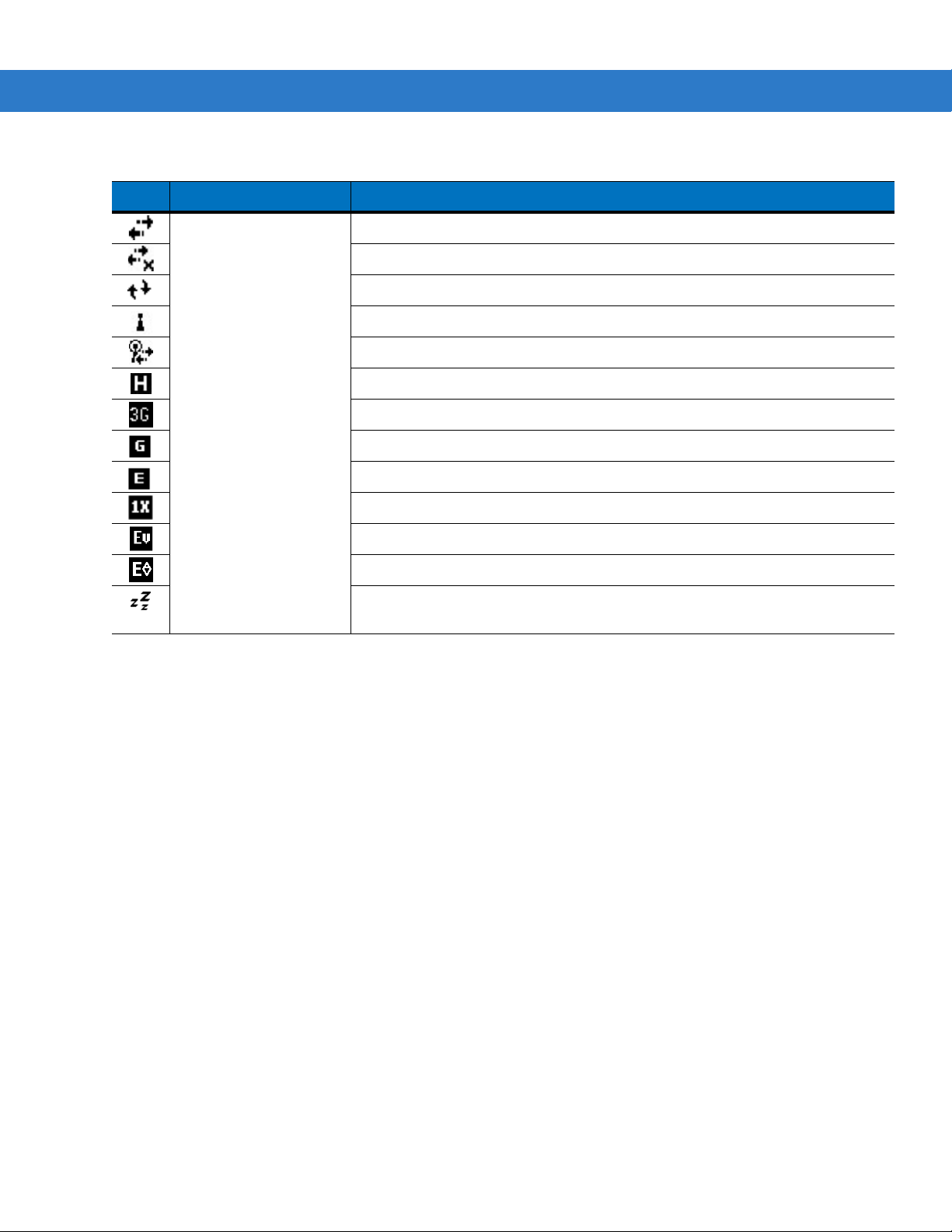
HSDPA available. (MC7506 and MC7596)
3G available. (MC7506 and MC7596)
GPRS available. (MC7506 and MC7596)
EGPRS available. (MC7506 and MC7596)
1xRTT available. (MC7508 and MC7598)
EVDO Rev. 0 available. (MC7508 and MC7598)
EVDO Rev. A available. (MC7508 and MC7598)
Dormant State - no data transmission during a 1x or EVDO connection.
(MC7508 and MC7598)
Page 38

2 - 4 MC75 User Guide
Table 2-1
Icon Function Description
Status Icons (Continued)
WAN Call missed.
Dialing while no SIM card is installed.
Voice call in progress.
Calls are forwarded.
Call on hold.
Speakerphone is on.
Antenna/signal icon: wireless on/good signal.
Antenna/signal icon: wireless off.
Antenna/signal icon: no service or searching.
HSDPA connecting. (MC7506 and MC7596)
HSDPA in use. (MC7506 and MC7596)
3G connecting. (MC7506 and MC7596)
3G in use. (MC7506 and MC7596)
GPRS connecting. (MC7506 and MC7596)
GPRS in use. (MC7506 and MC7596)
EGPRS connecting. (MC7506 and MC7596)
EGPRS in use. (MC7506 and MC7596)
EVDO connecting. (MC7508 and MC7598)
EVDO in use. (MC7508 and MC7598)
Roaming.
SIM Card not installed. (MC7506 and MC7596)
Speaker All sounds are on.
All sounds are off.
Vibrate is on.
Battery Main battery is charging.
Battery power completely depleted.
Main battery is low.
Main battery level.
Time and Next
Appointment
Displays current time in analog or digital format.
Page 39

Using the MC75 2 - 5
The command bar at the bottom of the screen can contain the task tray icons listed in Table 2-2.
Table 2-2
Icon Description
Programs
Table 2-3 lists the default programs on the Start menu.
Task Tray Icons
Wireless connection
Indicates WLAN signal strength.
status
Bluetooth Enabled Bluetooth radio is on.
Bluetooth Disabled Bluetooth radio is off.
Bluetooth Connection Bluetooth radio is connected to another Bluetooth device.
ActiveSync Active serial connection between the MC75 and the host computer.
NOTE On devices with Windows Mobile 6.5.3, see Start Screen on page C-8 for more information.
Table 2-3
Programs in the Start Menu
Icon Name Description
Office Mobile
Use the complete suite of Microsoft
device.
Excel Mobile - Create new workbooks or view and edit Microsoft
®
Excel
workbooks.
OneNote Mobile - Create new notes or view existing notes.
PowerPoint Mobile - View Microsoft
presentations.
Word Mobile - Create, view, and edit Microsoft
Calendar Keep track of appointments and create meeting requests.
Contacts Keep track of friends and colleagues.
Internet Explorer Mobile Browse Web and WAP sites as well as download new programs and
files from the Internet.
®
Office applications for your mobile
®
®
PowerPoint® slides and
®
Word documents.
Page 40

2 - 6 MC75 User Guide
Table 2-3
Table 2-4 lists programs that are listed in the Programs window.
Table 2-4
Programs in the Start Menu
Icon Name Description
Messaging Send and receive e-mail, and text messages.
Phone Make and receive calls, switch between calls, and set up conference
calling.
Help See Help topics for the current screen or program.
Programs in Program Window
Icon Name Description
ActiveSync Synchronize information between the MC75 and a host computer or the
Exchange Server.
AirBEAM Allows specially designed software packages to be transferred between
a host server and the MC75. Refer to the MC75 Integrator Guide for
more information.
BT Information Displays information about the Bluetooth radio. See
BTExplorer Manages Bluetooth StoneStreet One Bluetooth connections. Refer to
the MC75 Integrator Guide for more information. Appears only if the
StoneStreet One Bluetooth stack is enabled.
BT ScannerCtlPanel Configures the COM port used with Bluetooth scanners.
Calculator Perform basic arithmetic and calculations, such as addition,
subtraction, multiplication, and division.
Display_BD_Address Displays the MC75’s Bluetooth address in a bar code format.
File Explorer Organize and manage files on your device.
Internet Sharing Connect a notebook computer to the Internet using the MC75's data
connection.
Page 41

Using the MC75 2 - 7
Table 2-4
Programs in Program Window (Continued)
Icon Name Description
Messenger Use this mobile version of Windows Live Messenger.
Modem Link Enables the MC75 to be used as a modem.
MSP Agent Interacts with MSP agents to collect monitoring and asset information
to enable the configuration, provisioning, monitoring and
troubleshooting of the MC75. Refer to the MC75 Integrator Guide for
more information.
Notes Create handwritten or typed notes, drawings, and voice recordings.
Pictures & Videos View and manage pictures, animated GIFs, and video files.
Rapid Deployment Facilitates software downloads from a Mobility Services Platform Console
FTP server to the MC75.
information.
Refer to the MC75 Integrator Guide for more
Remote Desktop Log onto Windows NT server type computers and use all of the programs
that are available on that computer from the MC75.
Search Search contacts, data, and other information on your MC75.
SIM Toolkit Manage the contacts that are stored on your SIM card. Copy SIM
contents to Contacts on the MC75.
SMS Staging Used to push a staging profile to the MC75.
Tas ks Keep track of your tasks.
Windows Live Use this mobile version of Windows Live™ to find information on the
web.
Windows Media Player
Mobile
Play back audio and video files.
Page 42

2 - 8 MC75 User Guide
Settings
NOTE On devices with Windows Mobile 6.5.3, see Start Screen on page C-8 for more information.
Table 2-5 lists control applications pre installed on the MC75. Tap Start > Settings to open the Settings window.
Table 2-5
Personal Tab
Settings in the Setting Window
Icon Name Description
Buttons Assign a program to a button.
Input Set options for each of the input methods.
Lock Set a password for the MC75.
Menus Set what programs appear in the Start menu.
Owner Information Enter personal information on the MC75.
Phone Make and receive calls, switch between calls, and set up conference
calling.
System Tab
Sounds & Notifications Enable sounds for events, notifications, and more, and set the type of
notification for different events.
Today Customize the appearance and the information to be displayed on the
Today screen.
About
Backlight Set the display backlight time-out and adjust brightness.
Certificates See information about certificates installed on the MC75.
View basic information such as the Windows Mobile
of processor used on the MC75.
®
version and type
Page 43
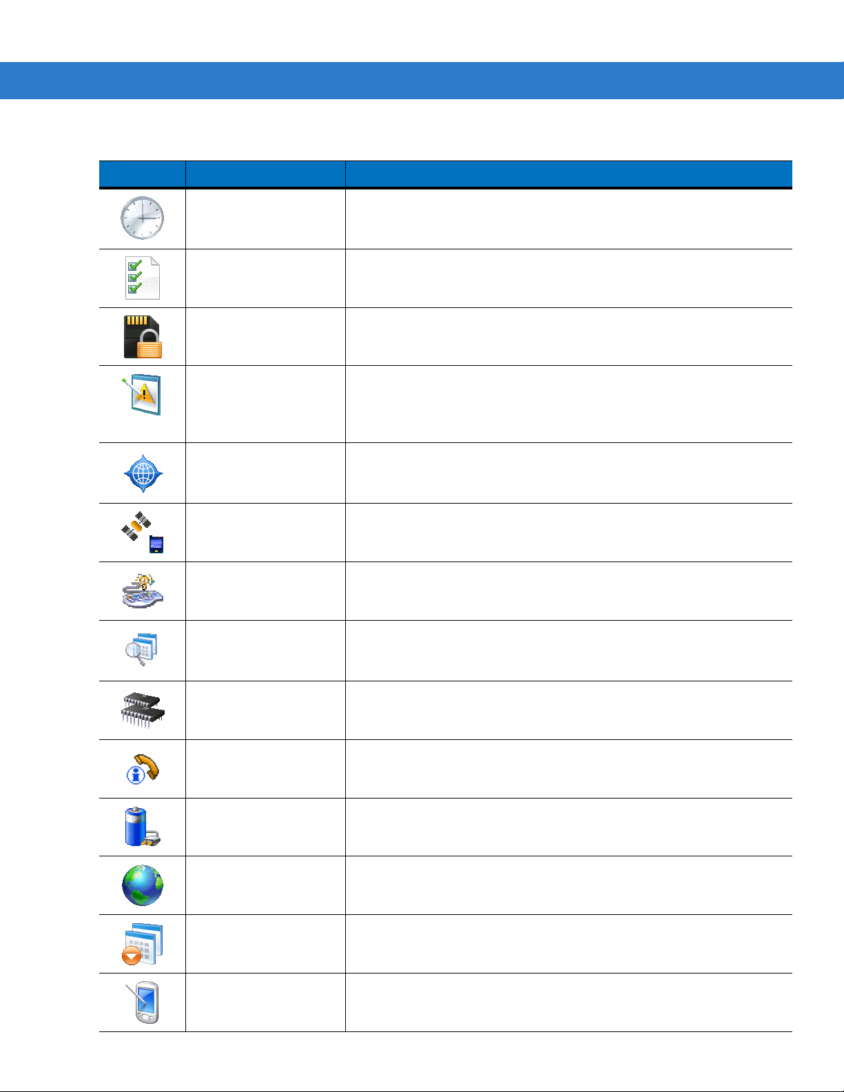
Using the MC75 2 - 9
Table 2-5
Settings in the Setting Window (Continued)
Icon Name Description
Clock & Alarms Set the device clock to the date and time of your locale or to a visiting
time zone when you’re traveling. Alarms can also be set at specified
days and times of a week.
Customer Feedback Submit feedback on the Windows Mobile 6 software.
Encryption Allow files on a storage card to be encrypted. Encrypted files are
readable only on your device.
Error Reporting Enable or disable the device's error reporting function. When this
function is enabled and a program error occurs, technical data about
the state of the program and your computer is logged in a text file and
delivered to Microsoft's technical support if you choose to send it.
External GPS Set the appropriate GPS communication ports, if required. You may
need to do this when there are programs on your device that access
GPS data or you have connected a GPS receiver to the MC75.
GPS Setup View GPS SUPL information.
Keylight Set the keypad backlight time-out.
Managed Programs Lists applications that have been installed remotely by your system
administrator. Refer to the Microsoft Applications for Windows Mobile 6
User Guide for more information.
Memory Check the device memory allocation status and memory card
information and stop currently running programs.
Phone Info Displays the phone version information.
Power Check battery power and set the time-out for turning off the display to
conserve battery power.
Regional Settings Set the regional configuration to use, including the format for displaying
numbers, currency, date, and time on the MC75.
Remove Programs Remove programs that you installed on the MC75.
Screen Change the screen orientation, re-calibrate the screen, and change the
screen text size.
Page 44
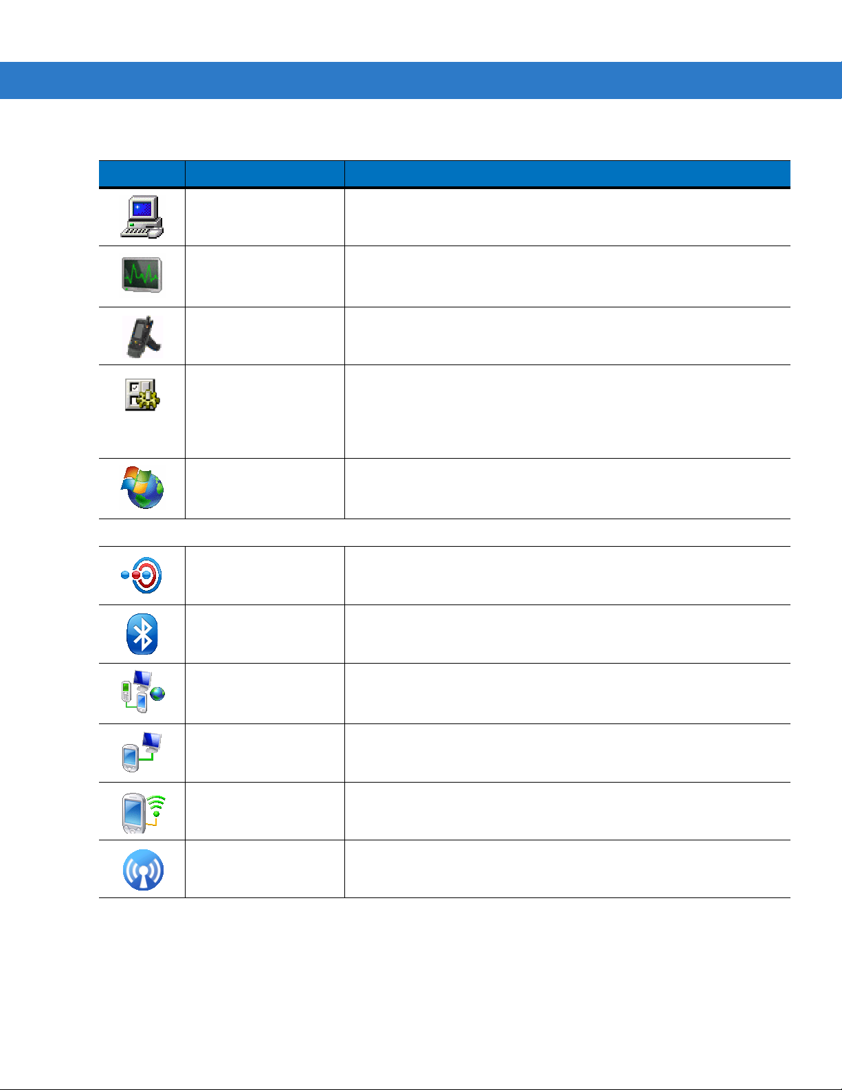
2 - 10 MC75 User Guide
Table 2-5
Connections Tab
Settings in the Setting Window (Continued)
Icon Name Description
System Info Displays the MC75’s software and hardware information.
Task Manager Enables viewing of memory and CPU allocations and stops running
processes. Refer to the Microsoft Applications for Windows Mobile 6
User Guide for more information.
Trigger Settings Enables the MC75 to be used with the TRG7000 Trigger Handle.
USB Config Configures the USB port. Set the port mode to either USB Client or
USB host. USB Client mode has two options: ActiveSync and Mass
Storage. USB Mass Storage allows a device partition (storage card,
application or cache disk) to be seen on the host computer as a USB
flash memory drive instead of ActiveSync.
Windows Update Link to Microsoft's web site and update Windows Mobile® on your
device with the latest security patches or fixes. Do not use. Obtain
updates from Zebra.
Beam Set the MC75 to receive incoming IrDA beams.
Bluetooth Enables Bluetooth radio and functionality. See Chapter 4, Using
Bluetooth for more information.
Connections Set up one or more types of modem connections for your device, such
as phone dial-up, GPRS, Bluetooth, and more, so that your device can
connect to the Internet or a private local network.
USB to PC Enables or disables the enhanced network connectivity.
Wi-Fi Setup wireless network connection and customize settings.
Wireless Manager Enables or disables the MC75’s wireless radios and customizes Wi-Fi,
Bluetooth and Phone settings.
Page 45

Adjusting Volume
NOTE On devices with Windows Mobile 6.5.3, see Status Bar on page C-5 for more information.
To adjust the system volume using the Speaker icon in the navigation bar:
1. Tap the Speaker icon. The Volume dialog box appears.
Using the MC75 2 - 11
Figure 2-2
2. Tap and move the slide bar to adjust the volume.
3. Select the On or Off radio button to turn the volume on or off.
You can also adjust the system volume using the So
the side of the MC75.
Volume Dialog Box
Battery Status Indications
Battery icons appear on the navigation bar indicating the battery power level. When the main battery or backup
battery power falls below a predetermined level the icon indicates the status and a battery dialog box appears
indicating the status of the main or backup battery.
unds & Notifications window, or use the Up/Down button on
Figure 2-3
Battery Status Dialog Box
Page 46

2 - 12 MC75 User Guide
The Battery icon always appears in the navigation bar when the Today screen is visible. The icon indicates the
battery power level. The message displays until the Dismiss button is pressed.
Figure 2-4
Also view the battery status using the Power window
Battery Icon on the Title Bar
.
Battery Reserve Options
If the charge of the battery reaches a critical threshold, the MC75 shuts down. This threshold can be changed but
affects the amount of time that data can be retained.
1. Ta p Start > Settings > Power icon > RunTime tab. A warning message appears.
Figure 2-5
Warning Message
2. Read the warning message and tap ok.
Figure 2-6
3. Select one of the Battery Reserve Options.
•
•
RunTime Tab
Option 1: Minimum - After a low battery shutdown, data will be retained for minimum amount of time.
Battery should be replaced immediately to avoid data loss.
Option 2: Less - After a low battery shutdown, data will be retained for less than normal amount of time.
Page 47

Using the MC75 2 - 13
•
Option 3: Normal - After a low battery shutdown, data will be retained for maximum amount of time.
4. Ta p ok.
Main Battery Temperature Notifications
The temperature notification system implements three levels of notification when the temperature within the battery
exceeds specific temperature thresholds:
•
Level 1: Temperature Watch; this level is similar to main battery low warning. It indicates that the battery
temperature has reached the first threshold level. The user should move to an environment within proper
operating temperature.
•
Level 2: Temperature Warning; this level is similar to main battery very low warning. It indicates the battery
temperature has reached the second threshold level. The user should stop using the MC75.
•
Level 3: Temperature Error; this level indicates the battery has reached an unusable temperature threshold
and immediately suspends the MC75. This level does not have any graphical notification associated with it.
Figure 2-7
Figure 2-8
Main Battery Temperature Watch Dialog Box
Main Battery Temperature Warning Dialog Box
NOTE The Temperature Warning dialog box remains visible until you tap Hide.
Page 48
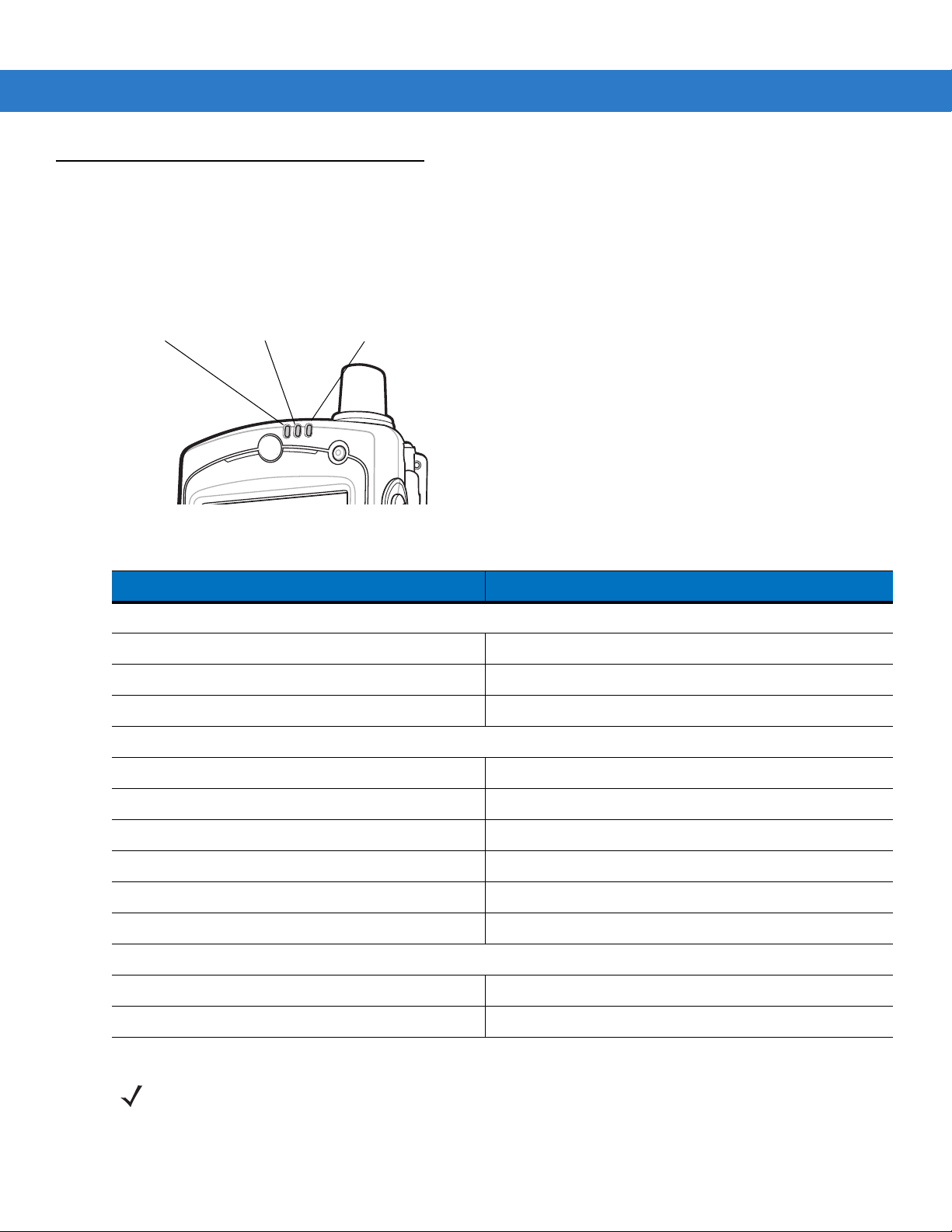
2 - 14 MC75 User Guide
Radio Status
LED
Scan/Decode
LED
Charging/Battery
Status LED
LED Indicators
The MC75 has three LED indicators. The Scan/Decode LED indicates status for bar code scanning. The
Charging/Battery Status LED indicates battery charging and status. The Radio Status LED indicates WAN radio
status. Table 2-6 describes the LED indications.
Figure 2-9
Table 2-6
LED Indicators
LED Indications
LED State Indication
Scan/Decode LED
Solid Green Successful decode/capture.
Solid Red Laser enabled, scanning/imaging in process.
Off Not enabled.
Charging/Battery Status LED
Slow Blinking Amber Main battery in MC75 is charging.
Solid Amber Main battery in MC75 is fully charged.
Fast Blinking Amber Charging error.
Off Not charging.
Single Blink Amber (when Power button pressed) Battery depleted.
Blinking Amber (when Power button pressed) Battery over-temperature condition.
Radio Status LED
Slow Blinking Green WAN radios is on.
Off WAN radio is off.
NOTE For information about scanning/decoding, see Data Capture on page 2-34. For information about WAN radio
status and settings, see Chapter 5, Using the Phone, or refer to the MC
75 Integrator Guide.
Page 49

Resetting the MC75
There are two reset functions, warm boot and cold boot. A warm boot restarts the MC75 by closing all running
programs. A cold boot also restarts the MC75, and also resets the clock. Data saved in flash memory or a memory
card is not lost.
If the MC75 is not functioning properly, perform a warm boot first. If the MC75 still does not respond, perform a cold
oot.
b
Performing a Warm Boot
Hold down the Power button for approximately five seconds. As soon as the MC75 starts to boot release the
Power button.
Performing a Cold Boot
To perform a cold boot simultaneously press the Power button and the 1 and 9 keys.
Using the MC75 2 - 15
Waking the MC75
The wake-up conditions define what actions wake up the mobile computer after it has gone into suspend mode.
The mobile computer can go into suspend mode by either pressing the Power button or automatically by Control
Panel time-out settings. These settings are configurable and the factory default settings are shown in Table 2-7 are
subject to change/update.
Table 2-7
AC power is applied. No Yes
Mobile computer is inserted into a cradle. No Yes
Mobile computer is removed from a cradle. No Yes
Mobile computer is connected to a USB device. No Yes
Mobile computer is disconnected from a USB device. No Yes
A key is pressed. No Yes
The scan triggered is pressed. No Yes
The screen is touched. No No
Audio Jack No No
Wake-up Default Settings
Condition for Wake-up Power Button Automatic Time-out
Audio Btn No No
Bluetooth communication Yes Ye s
Incoming phone call Yes Yes
Page 50
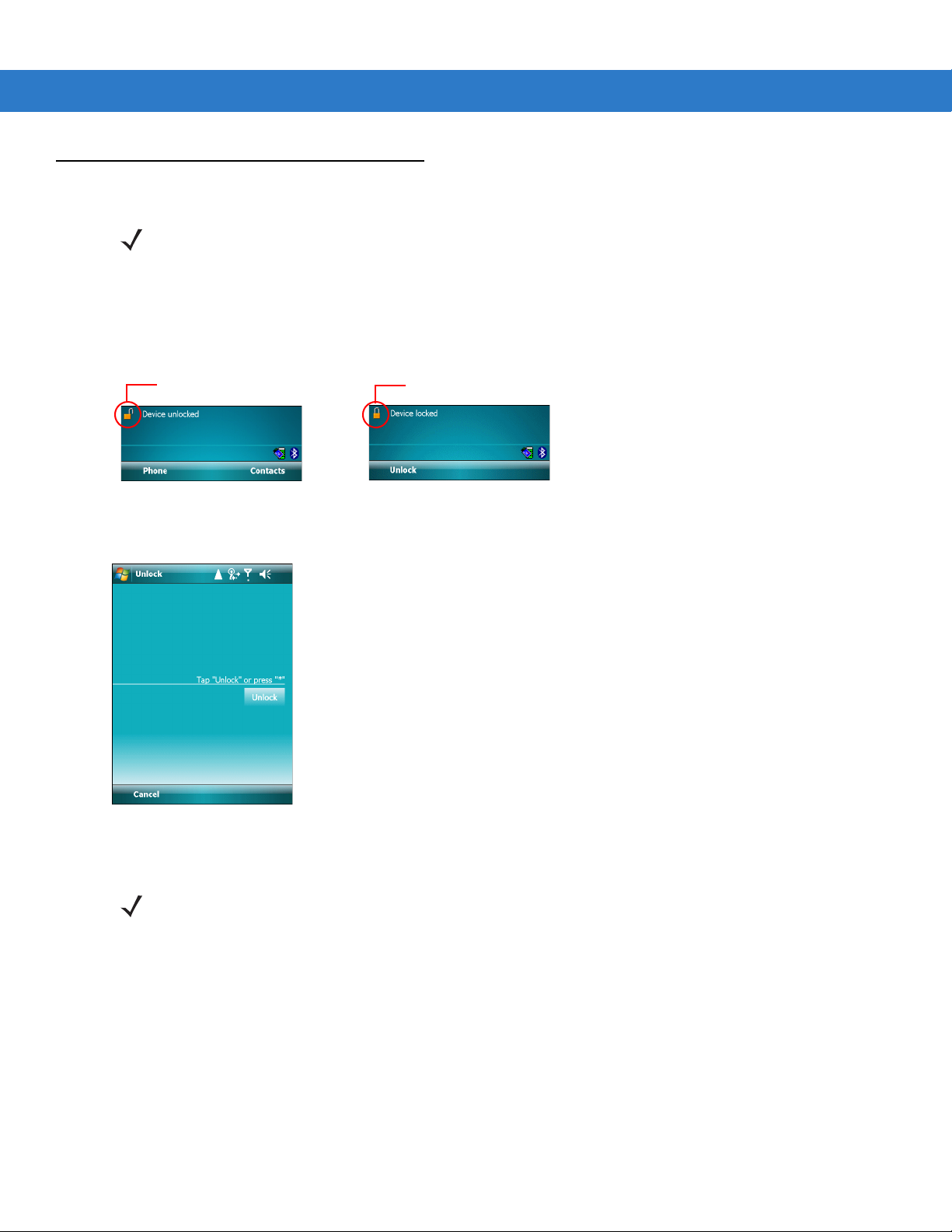
2 - 16 MC75 User Guide
Device Unlocked Icon Device Locked Icon
Locking the MC75
NOTE On devices with Windows Mobile 6.5.3, see Locking the MC75 on page C-15 for more information.
Use the Device Lock feature to prevent use of the device. Note that when locked, the MC75 does not respond to
screen or keypad input.
To lock the device, tap the Dev
Figure 2-10
To unlock the device and free it for use, tap Unlock.
Device Locked/Unlocked Icons
ice unlocked icon. The icon changes to locked.
Figure 2-11
Ta p Unlock on the
Unlock Device Window
Unlock window.
NOTE You can make emergency calls even when the MC75 is locked. See Making an Emergency Call on page 5-7
for more info
rmation.
Page 51

Keypads
F2
The MC75 offers two types modular keypad configurations: Numeric and alpha-numeric.
Numeric Keypad Configuration
The numeric keypad contains application keys, scroll keys, and function keys. The keypad is color-coded to
indicate the alternate function key (blue) values. Note that an application can change keypad functions so the
MC75’s keypad may not function exactly as described. See Table 2-8 for key and button descript
on page 2-19 for the keypad’s special functions.
Using the MC75 2 - 17
ions and Table 2-9
Figure 2-12
Table 2-8
Blue Key (left)
Orange Key
MC75 Numeric Keypad Descriptions
Key Description
MC75 Numeric Keypad
Use this key to launch applications or access items (shown on the keypad in blue).
Press the Blue key once to activate this mode, followed by another key.
A single press displays the following icon at the bottom of the screen, until a second key is
essed:
pr
Use this key to access the secondary layer of characters and actions (shown on the keypad
in orange). Press the Orange key once to lock the keypad into Alpha state.
A single press displays the following icon at the bottom of the screen:
Press the Orange key a second time to return to the normal state.
Press the Orange key, then the Shift key to add a temporary shift (that applies only to the
xt key pressed) to the orange lock state. This displays the following icon at the bottom of
ne
the screen:
Page 52

2 - 18 MC75 User Guide
Table 2-8
Ta lk / En d
Scan (yellow)
Scroll Up and Down
Scroll Left and Right
Soft Keys
Star
MC75 Numeric Keypad Descriptions (Continued)
Key Description
Talk (Green Phone): press to display the phone keypad window or to dial a phone number
(from the phone keypad window).
End (Red Phone): press when the phone keypad window displays to stop dialing or end a
call.
Activates the scanner/imager in a scan enabled application.
Moves up one item.
Moves left one item when pressed with the Orange key.
Moves down one item.
Moves right one item when pressed with the Orange key.
Accesses the command or menu above it on the screen.
Produces an asterisk in default state.
Press and release the blue key, then press the Star key to open the St
art menu.
Alphanumeric
SPACE
BACKSPACE
In default state, produces the numeric value on the key.
In Alpha state, produces the lower case alphabetic characters on the key. Each key press
oduces the next alphabetic character in sequence. For example, press and release the
pr
Orange key and then press the ‘4’ key once to produce the letter ‘g’; press and release the
Orange key and then press the ‘4’ key three times to produce the letter ‘i’.
Press the SHIFT key in Alpha state to produce the upper case alphabetic characters on the
y. For example, press and release the Orange key, press and release the SHIFT key, and
ke
then press the ‘4’ key once to produce the letter ‘G’; press and release the Orange key,
press and release the SHIFT key and then press the ‘4’ key three times to produce the letter
‘I’.
Produces a space.
Produces a backspace.
Page 53

Using the MC75 2 - 19
Table 2-8
SHIFT
ENT (Enter)
Pound
MC75 Numeric Keypad Descriptions (Continued)
Key Description
Press and release the SHIFT key to activate the keypad alternate SHIFT functions.
A single press displays the following icon at the bottom of the screen, until a second key is
pr
essed:
Press the Orange key, then the Shift key to add a temporary shift (that applies only to the
next key pressed) to the orange lock state. This displays the following icon at the bottom of
the screen:
Executes a selected item or function.
Produces a pound/number sign.
Press and release the blue key, then press the Pound key to produce an OK.
Table 2-9
Key
1 1 F1 ! * * * * * * * *
2 2 F2 @ a b c A B C
3 3 F3 # d e f D E F
4 4 F4 $ g h i G H I
5 5 F5 % j k l J K L
6 6 F6 ^ m n o M N O
7 7 F7 & p q r s P Q R S
8 8 F8 * t u v T U V
9 9 F9 ( w x y z W X Y Z
0 0 F10 ) . >
Note: An application can change the key functions. The keypad may not function exactly as described.
Numeric Keypad Input Modes
Numeric Mode
Blue+
Key
SHIFT
+ Key
Orange Key
(Alpha Lowercase Mode)
1st
Press
2nd
Press
3rd
Press
4th
Press
Orange + Shift Keys
(Alpha Uppercase Mode)
1st
Press
2nd
Press
3rd
Press
4th
Press
Page 54

2 - 20 MC75 User Guide
Table 2-9
Key
Up Up Up Hilight UpLeft Left
Down Down Down Hilight
Enter Action Action Action Action Action
Note: An application can change the key functions. The keypad may not function exactly as described.
Numeric Keypad Input Modes (Continued)
Numeric Mode
Blue+
Key
SHIFT
+ Key
Down
(Alpha Lowercase Mode)
1st
Press
Right Right
Orange Key
2nd
Press
3rd
Press
4th
Press
Orange + Shift Keys
(Alpha Uppercase Mode)
1st
Press
2nd
Press
3rd
Press
4th
Press
Page 55

Using the MC75 2 - 21
DSD Keypad Configuration
The DSD keypad contains application keys, scroll keys, and function keys. The keypad is color-coded to indicate
the alternate function key (blue) values. Note that an application can change keypad functions so the MC75’s
keypad may not function exactly as described. See Table 2-10 for key and button descriptions and Table 2-11 on
page 2-23 for the keypad’s special functions.
Figure 2-13
Table 2-10
Blue Key (left)
Orange Key
MC75 DSD Keypad Descriptions
Key Description
MC75 DSD Keypad
Use this key to launch applications or access items (shown on the keypad in blue).
Press the Blue key once to activate this mode, followed by another key.
A single press displays the following icon at the bottom of the screen, until a second key is
essed:
pr
Use this key to access the secondary layer of characters and actions (shown on the keypad
in orange). Press the Orange key once to lock the keypad into Alpha state.
A single press displays the following icon at the bottom of the screen:
Press the Orange key a second time to return to the normal state.
Press the Orange key, then the Shift key to add a temporary shift (that applies only to the
xt key pressed) to the orange lock state. This displays the following icon at the bottom of
ne
the screen:
Ta lk / En d
Scan (yellow)
Talk (Green Phone): press to display the phone keypad window or to dial a phone number
(from the phone keypad window).
End (Red Phone): press when the phone keypad window displays to stop dialing or end a
call.
Activates the scanner/imager in a scan enabled application.
Page 56

2 - 22 MC75 User Guide
Table 2-10
Scroll Up
Scroll Left
Scroll Down
Scroll Right
Alphanumeric
MC75 DSD Keypad Descriptions (Continued)
Key Description
Moves up one item.
Moves left one item.
Moves down one item.
Moves right one item.
In default state, produces the numeric value on the key.
In Alpha state, produces the lower case alphabetic characters on the key. Each key press
oduces the next alphabetic character in sequence. For example, press and release the
pr
Orange key and then press the ‘4’ key once to produce the letter ‘g’; press and release the
Orange key and then press the ‘4’ key three times to produce the letter ‘i’.
Press the SHIFT key in Alpha state to produce the upper case alphabetic characters on the
y. For example, press and release the Orange key, press and release the SHIFT key, and
ke
then press the ‘4’ key once to produce the letter ‘G’; press and release the Orange key,
press and release the SHIFT key and then press the ‘4’ key three times to produce the letter
‘I’.
SPACE
BACKSPACE
ESC
ENT (Enter)
Period
Dash
Produces a space.
Produces a backspace.
Cancels an operation or action.
Executes a selected item or function.
Produces a period character.
Produces a dash character.
Page 57

Using the MC75 2 - 23
Table 2-11
Key
1 1 F1 ! * * * * * * * *
2 2 F2 @ a b c A B C
3 3 F3 # d e f D E F
4 4 F4 $ g h i G H I
5 5 F5 % j k l J K L
6 6 F6 ^ m n o M N O
7 7 F7 & p q r s P Q R S
8 8 F8 * t u v T U V
9 9 F9 ( w x y z W X Y Z
0 0 F10 ) . >
. . . .
DSD Keypad Input Modes
Numeric Mode
Blue+
Key
SHIFT
+ Key
(Alpha Lowercase Mode)
1st
Press
Orange Key
2nd
Press
3rd
Press
4th
Press
Orange + Shift Keys
(Alpha Uppercase Mode)
1st
Press
2nd
Press
Press
3rd
4th
Press
- - - -
Up Up Up Hilight
Up
Down Down Down Hilight
Dow
n
Left Left Left Hilight
t
Lef
Right Right Right Hilight
t
Righ
Enter Action Action Action Action Action
ESC
Note: An application can change the key functions. The keypad may not function exactly as described.
ESC ESC ESC ESC ESC
Page 58

2 - 24 MC75 User Guide
Alpha-numeric Keypad Configurations
The three types of alpha-numeric keypads produce the 26-character alphabet (A-Z, both lowercase and
uppercase), numbers (0-9), and assorted characters. The keypad is color-coded to indicate which modifier key to
press to produce a particular character or action. The keypad default is alphabetic, producing lowercase letters.
See Table 2-12 for key and button descriptions and Table 2-13 on page 2-27 for the keypad’s special functions.
Figure 2-14
Figure 2-15
QWERTY Keypad Configuration
AZERTY Keypad Configuration
Figure 2-16
QWERTZ Keypad Configuration
Page 59
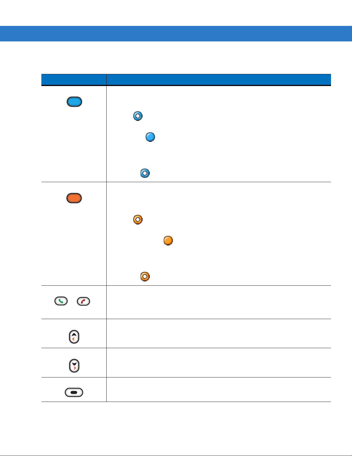
Using the MC75 2 - 25
Table 2-12
Blue Key Launches applications (shown on the keypad in blue).
Orange Key Accesses the secondary layer of characters and actions (shown on the keypad in
Alpha-numeric Keypad Descriptions
Key Action
Press the Blue key once to activate this mode temporarily, followed by another key. This
lays the following icon at the bottom of the screen, until a second key is
disp
pressed:
Press the Blue key twice to lock this mode. This displays the following icon at the bottom
of the screen:
Press the Blue key a third time to unlock.
Press and hold the Blue key while selecting a sequence of keys to activate this mode
temporar
is pressed:
orange).
Press the Orange key once to activate this mode temporarily, followed by another key.
This
pressed:
Press the Orange key twice to lock this mode. This displays the following icon at the
ily. This displays the following icon at the bottom of the screen as long as the key
displays the following icon at the bottom of the screen, until a second key is
bottom of the screen:
Press the Orange key a third time to unlock.
Press and hold the Orange key while selecting a sequence of keys to activate this mode
temporar
is pressed:
Ta lk /E nd Talk (Green Phone): press to display the phone keypad window or to dial a phone number
(from the phone keypad window).
End (Red Phone): press when the phone keypad window displays to stop dialing or end a
call.
Scroll Up and Left
Scroll Down and Right
Soft Keys
Moves up one item.
Moves left one item when pressed with the Orange key.
Moves down one item.
Moves right one item when pressed with the Orange key.
Accesses the command or menu above it on the screen.
ily. This displays the following icon at the bottom of the screen as long as the key
Page 60

2 - 26 MC75 User Guide
Table 2-12
Shift
Backlight Turns the display backlight on and off.
Backspace
Enter
Alpha-numeric Keypad Descriptions (Continued)
Key Action
Changes the state of the alpha characters from lowercase to uppercase.
•
Press the Shift key to activate this mode temporarily, followed by another key.
This displays the following icon at the bottom of the screen, until a second key is
pressed:
•
Press the Shift key twice to lock this mode. This displays the following icon at the
bottom of the screen:
•
Press the Shift key a third time to unlock.
Produces a backspace.
Executes a selected item or function.
Star
OK
Start Menu
Menu
Phonepad
Produces an asterisk.
Use this key in conjunction with the Blue key as an OK or close button. This function is
user programmable.
Use this key in conjunction with the Blue key to instantly display the Start menu from any
application without tapping the screen. This function is user programmable.
Use this key in conjunction with the Blue key to instantly display the context menu from
any application without tapping the screen. This function is user programmable.
Use this key in conjunction with the Blue key to display the Phonepad application
without tapping the screen. This function is user programmable.
Page 61

Using the MC75 2 - 27
Table 2-13
Q q Q * Start Menu
W w W 1 Menu
E e E 2 Phone
R r R 3
T t T +
Y y Y _
U u U -
I i I =
O o O “
P p P áü OK
A a A #
S s S 4
D d D 5
QWERTY Keypad Input Modes
Key Normal Shift + Key Orange + Key Blue + Key
F f F 6
G g G (
H h H )
J j J /
K k K :
L l L ‘
Backspace Backspace
Shift Shift
Z z Z 7
X x X 8
C c C 9
V v V %
B b B &
N n N !
M m M ?
, , < @
Note: An application can change the key functions. The keypad may not function exactly as described.
Page 62

2 - 28 MC75 User Guide
Table 2-13
ENTER Enter
Backlight Backlight Backlight 0 Backlight
TAB Tab Ta b Back tab Ta b
SPACE Space Space Space Space
Star * * * *
. . > . .
Note: An application can change the key functions. The keypad may not function exactly as described.
Table 2-14
A a A * Start Menu
Z z Z 1 Menu
E e E 2 Phone
QWERTY Keypad Input Modes (Continued)
Key Normal Shift + Key Orange + Key Blue + Key
AZERTY Keypad Input Modes
Key Normal Shift + Key Orange + Key Blue + Key
R r R 3
T t T +
Y y Y _
U u U -
I i I =
O o O “
P p P áü OK
Q q Q #
S s S 4
D d D 5
F f F 6
G g G (
H h H )
J j J /
K k K :
L l L ‘
M m M ?
Note: An application can change the key functions. The keypad may not function exactly as described.
Page 63

Using the MC75 2 - 29
Table 2-14
Shift Shift
W w W 7
X x X 8
C c C 9
V v V %
B b B &
N n N !
, , < @
Backspace backspace
Enter Enter
Backlight Backlight Backlight 0 Backlight
TAB Tab Ta b Back tab Ta b
SPACE Space Space Space Space
AZERTY Keypad Input Modes (Continued)
Key Normal Shift + Key Orange + Key Blue + Key
Star * * * *
. . > . .
Note: An application can change the key functions. The keypad may not function exactly as described.
Table 2-15
Q q Q * Start Menu
W w W 1 Menu
E e E 2 Phone
R r R 3
T t T +
Z z Z _
U u U -
I i I =
O o O “
QWERTZ Keypad Input Modes
Key Normal Shift + Key Orange + Key Blue + Key
P p P áü OK
A a A #
Note: An application can change the key functions. The keypad may not function exactly as described.
Page 64

2 - 30 MC75 User Guide
Table 2-15
S s S 4
D d D 5
F f F 6
G g G (
H h H )
J j J /
K k K :
L l L ‘
Backspace Backspace
Shift Shift
Y y Y 7
X x X 8
C c C 9
QWERTZ Keypad Input Modes (Continued)
Key Normal Shift + Key Orange + Key Blue + Key
V v V %
B b B &
N n N !
M m M ?
, , < @
ENTER Enter
Backlight Backlight Backlight 0 Backlight
TAB Tab Ta b Back tab Ta b
SPACE Space Space Space Space
Star * * * *
. . > . .
Note: An application can change the key functions. The keypad may not function exactly as described.
Special Character Key
NOTE Special characters are only available on the alpha-numeric keypad configurations.
To add special characters using the MC75 áü key, type the related character first, then press the Orange twice
followed by the áü (P) key. Continue pressing the áü key until the special character displays. To modify an existing
Page 65

Using the MC75 2 - 31
character, move the cursor to the right of the character then press the Orange key twice and then press the áü key
until the special character replaces the original character. Table 2-16 lists the special characters you can generate.
Table 2-16
a A
c C
d D
e E
i I
l L
n N
o O
p P
r R
s S
t T
u U
Special Characters
Key Special Characters Key Special Characters
y Y
z Z
$ /
“ (
) +
! .
* @
% ,
# &
_ ‘
? :
-
Page 66
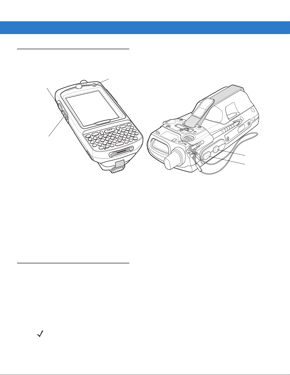
2 - 32 MC75 User Guide
Scan/Action
Button
Power Button
Up/Down Button
Action Button
Scan/Action
Button
Function Buttons
The MC75’s buttons perform certain functions.
Stylus
Figure 2-17
•
•
•
•
Use the MC75 stylus to select items and enter information. The stylus functions as a mouse.
•
•
•
Function Buttons
Power: Press the red Power button to turn the MC75 screen on and off. The MC75 is in suspend mode when
the screen is off. For more information, see Powering On the MC75 on page 1-8. Also use the Power bu
to reset the MC75 by performing a wa
Scan/Action: Press to scan bar codes or capture images. See Data Capture on page 2-34.
Or, press to open an application or perform a function. See the M
Guide to set an application to open.
Up/Down: Press to increase or decrease the MC75’s volume.
Action: Press to open an application or perform a function. See the Microsoft® Applications for Mobile 6
User Guide to set an application to open.
Tap: Touch the screen once with the stylus to press option buttons and open menu items.
Tap and Hold: Tap and hold the stylus on an item to see a list of actions available for that item. On the pop-up
menu that appears, tap the action to perform.
Drag: Hold the stylus on the screen and drag across the screen to select text and images. Drag in a list to
select multiple items.
rm or cold boot. See Resetting the MC75 on page 2-15.
icrosoft® Applications for Mobile 6 User
tton
NOTE Zebra recommends using the spring-loaded tip of the stylus to write on the screen, and the back end of the
stylus to tap the screen. Use your finger to press the Power button and keypad buttons.
Page 67
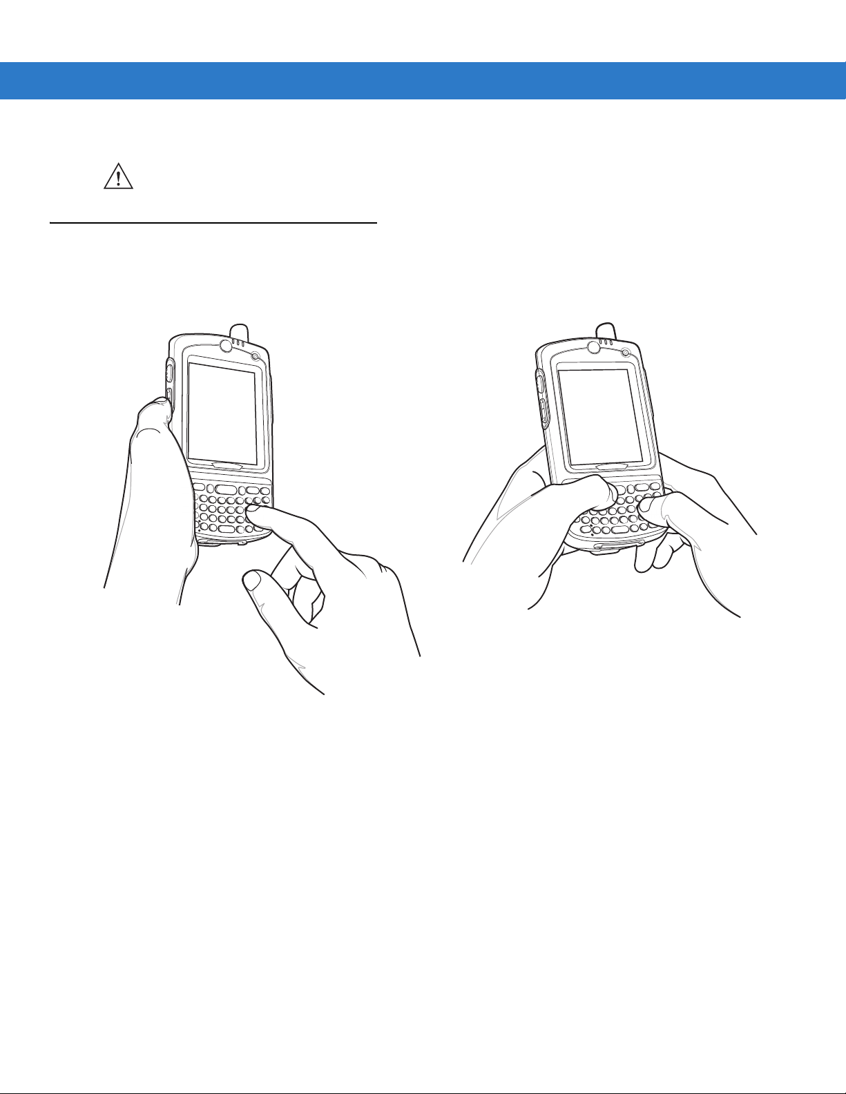
Single-hand Method
Two-hand Method
CAUTION To prevent damage to the screen, do not use any device other than the Zebra-provided stylus.
Entering Data
When entering data on the keypad, use either the single-hand method or the two-hand method as shown in Figure
2-18.
Using the MC75 2 - 33
Figure 2-18
Entering Data on the Keypad
Page 68

2 - 34 MC75 User Guide
Data Capture
The MC75 offers three types of data capture options:
•
Linear scanning
•
Imaging
•
Digital camera.
NOTE To perform data capture a scanning enabled application must be installed on the MC75. A sample scanning
application can be downloaded from the Zebra Support site at http://www.zebra.com/support.
Linear Scanning
MC75 with an integrated linear scanner have the following features:
•
Reading of a variety of bar code symbologies, including the most popular linear, postal, and 1-D code types.
•
Intuitive aiming for easy point-and-shoot operation.
Imaging
MC75 with an integrated imager have the following features:
•
Omnidirectional reading of a variety of bar code symbologies, including the most popular linear, postal,
PDF417, and 2D matrix code types.
•
The ability to capture and download images to a host for a variety of imaging applications.
•
Advanced intuitive laser aiming for easy point-and-shoot operation.
The imager uses digital camera technology to take a digital pictu
memory, and executes state-of-the-art software decoding algorithms to extract the data from the image.
Operational Modes
MC75 with an integrated imager support three modes of operation, listed below. Activate each mode by pulling the
trigger or pressing the Scan button.
•
Decode Mode: In this mode, the MC75 attempts to locate and decode enabled bar codes within its field of
view. The imager remains in this mode as long as you hold the trigger, or until it decodes a bar code.
NOTE To enable Pick List Mode, download the Control Panel applet from the web site at
http://www.zebra.com/support. Pick List can also be set in an application using a API command.
•
Pick List Mode: This mode allows you to selectively decode a bar code when more than one bar code is in
the MC75’s field of view. To accomplish this, move the aiming crosshair over the required bar code to decode
only this bar code. This feature is ideal for pick lists containing multiple bar codes and manufacturing or
transport labels containing more than one bar code type (either 1D or 2D).
re of a bar code, stores the resulting image in its
•
Image Capture Mode: Use this mode to capture an image within the MC75’s field of view. This is useful for
capturing signatures or images of items like damaged boxes.
Page 69

Digital Camera
MC75 with an integrated digital camera have the following features:
•
Omnidirectional reading of a variety of bar code symbologies, including the most popular linear, postal,
PDF417, and 2D matrix code types.
•
Advanced intuitive aiming for easy point-and-shoot operation.
Using the MC75 2 - 35
The camera uses digital camera technology to take a digital
memory, and executes state-of-the-art software decoding algorithms to extract the data from the image.
picture of a bar code, stores the resulting image in its
Scanning Considerations
Typically, scanning is a simple matter of aim, scan, and decode and a few quick trial efforts master it. However,
consider the following to optimize scanning performance:
•
Range
Any scanning device decodes well over a particular wo
the bar code. This range varies according to bar code density and scanning device optics.
Scanning within range brings quick and constant decode
decodes. Move the scanner closer and further away to find the right working range for the bar codes being
scanned.
•
Angle
Scanning angle is important for promoting qu
scanner from the bar code, this specular reflection can “blind” the scanner.
To avoid this, scan the bar code so that the beam does no
an angle; the scanner needs to collect scattered reflections from the scan to make a successful decode.
Practice quickly shows what tolerances to work within.
•
Hold the MC75 farther away for larger symbols.
•
Move the MC75 closer for symbols with bars that are close together.
ick decodes. When laser beams reflect directly back into the
rking range — minimum and maximum distances from
s; scanning too close or too far away prevents
t bounce directly back. But don’t scan at too sharp
NOTE Scanning procedures depend on the application and MC75 configuration. An application may use different
scanning procedures from the one listed above.
Linear Scanning
1. Ensure that a scan enabled application is loaded on the MC75.
2. Aim the scan window at the bar code.
Page 70

2 - 36 MC75 User Guide
Incorrect
Correct
Figure 2-19
3. Press the scan button. Ensure the red scan beam covers the entire bar code. The Scan/Decode LED lights red
Linear Scanning
to indicate that scanning is in process, then lights green and a beep sounds, by default, to indicate the bar code
was decoded successfully.
Figure 2-20
Linear Scanner Aiming Pattern
Imager Scanning
1. Ensure that a scan-enabled application is loaded on the MC75.
2. Aim the scan window at the bar code.
Figure 2-21
3. Press the scan button. The red laser aiming pattern turns on to assist in aiming. Ensure the bar code is within
Imager Scanning
the area formed by the brackets in the aiming pattern. The Scan/Decode LED lights red to indicate that
scanning is in process, then lights green and a beep sounds, by default, to indicate the bar code was decoded
successfully. Note that when the MC75 is in Pick List Mode, the imager does not decode the bar code until the
crosshair touches the bar code.
Page 71

Linear bar code
PDF417 symbol
Symbol
View Finder
(Aiming Pattern)
Correct
Using the MC75 2 - 37
Correct
Incorrect
Figure 2-22
Figure 2-23
Figure 2-24
Imager Aiming Pattern: Bar Code Centered
Imager Aiming Pattern: Bar Code Not Centered
Pick List Mode with Multiple Bar Codes in Aiming Pattern
4. Release the scan button.
Digital Camera Scanning
NOTE Imager decoding usually occurs instantaneously. The MC75 repeats the steps required to take a digital
picture (image) of a poor or difficult bar code as long as the scan button remains pressed.
1. Ensure that a scan-enabled application is loaded on the MC75.
2. Aim the camera lens on the back of the MC75 at a bar code.
3. Press and hold the scan button. A preview window appears on the display window with a red aiming reticle in
the center. The Scan/Decode LED lights red to indicate that scanning is in process.
Page 72

2 - 38 MC75 User Guide
Figure 2-25
4. Move the MC75 until the red aiming reticle is on the bar code to scan. The aiming reticle turns green when the
Sample Scan Application with Preview Window
MC75 is able to decode the bar code.
Figure 2-26
5. Release the scan button. The Scan/Decode LED lights green and a beep sounds, by default, to indicate the
Digital Camera Scanning
bar code was decoded successfully.
Using the RS507 Hands-free Imager
An RS507 Hands-free Imager can be used with the MC75 to capture bar code data.
NOTE OEM version 02.35.000 or higher is required.
To set up the RS507:
1. Ta p Start > Programs > BTScannerCtlPanel icon.
2. If required, select the BT Scanner checkbox and then select the appropriate Com port from the drop-down list.
3. Ta p Save and Exit.
4. Ta p Start > Programs > BD Address icon. A bar code displays.
5. Point the RS507 to the bar code. The RS507 reads the bar code and begins pairing with the MC75.
Page 73

Refer to the RS507 Hands-free Imager Product Reference Guide for more information.
Taking Photos
To take a photo:
1. Ta p Start > Programs > Pictures & Videos icon.
2. Ta p Camera on the command bar.
3. Check the image on the view finder, adjust if necessary.
4. Press the Enter key to take the picture. Hold the MC75 still until the camera flash occurs or the shutter sound
is heard.
Recording Video
To record a video clip:
Using the MC75 2 - 39
1. Ta p Start > Programs > Pictures & Videos icon.
2. Ta p Camera on the command bar.
3. Ta p Menu > Video to set shooting mode to video.
The available recording time displays on the screen.
NOTE By default, the time limit for recording videos is set to 30 seconds.
4.
Press the Enter key to begin recording.
Recording stops when you press the Enter bu
Viewing Photos and Videos
NOTE For detailed information on the Photos and Videos, refer to the Microsoft Applications User Guide for
Mobile 6, p/n 72E-108299-xx.
To view photos and video clips:
1. Ta p Start > Programs > Pictures & Videos icon.
2. Tap the picture or video clip to view.
tton again.
Page 74

2 - 40 MC75 User Guide
Using IrDA
In a Microsoft Windows Mobile program (except Messaging), and Picture & Videos, you can exchange files using
either infrared or Bluetooth.
NOTE You can also beam files (not folders) from the File Explorer window. Tap and hold the item you want to
send, then tap
First activate the beam function before exchanging files with another IrDA device.
To activate the Beam function:
1. Ta p Start > Settings > Connections tab > Beam icon.
2. Ta p Receive all incoming beams check box.
Beam File from the pop-up menu.
Figure 2-27
3. Ta p ok.
Beam Window
Infrared Connection
Using infrared, you can enable short-range file exchange between your MC75 and another IrDA device.
Exchanging Files using IR Connection
Ensure that the IrDA function on both the MC75 and the other device are enabled.
To send files via IrDA connection:
1. Switch to the program where you created the item you want to send and locate the item in the list.
NOTE Do not cover or block the IrDA window.
2. Align the IrDA port of the MC75 with that of the IrDA device so that they are unobstructed and within a close
range.
Page 75
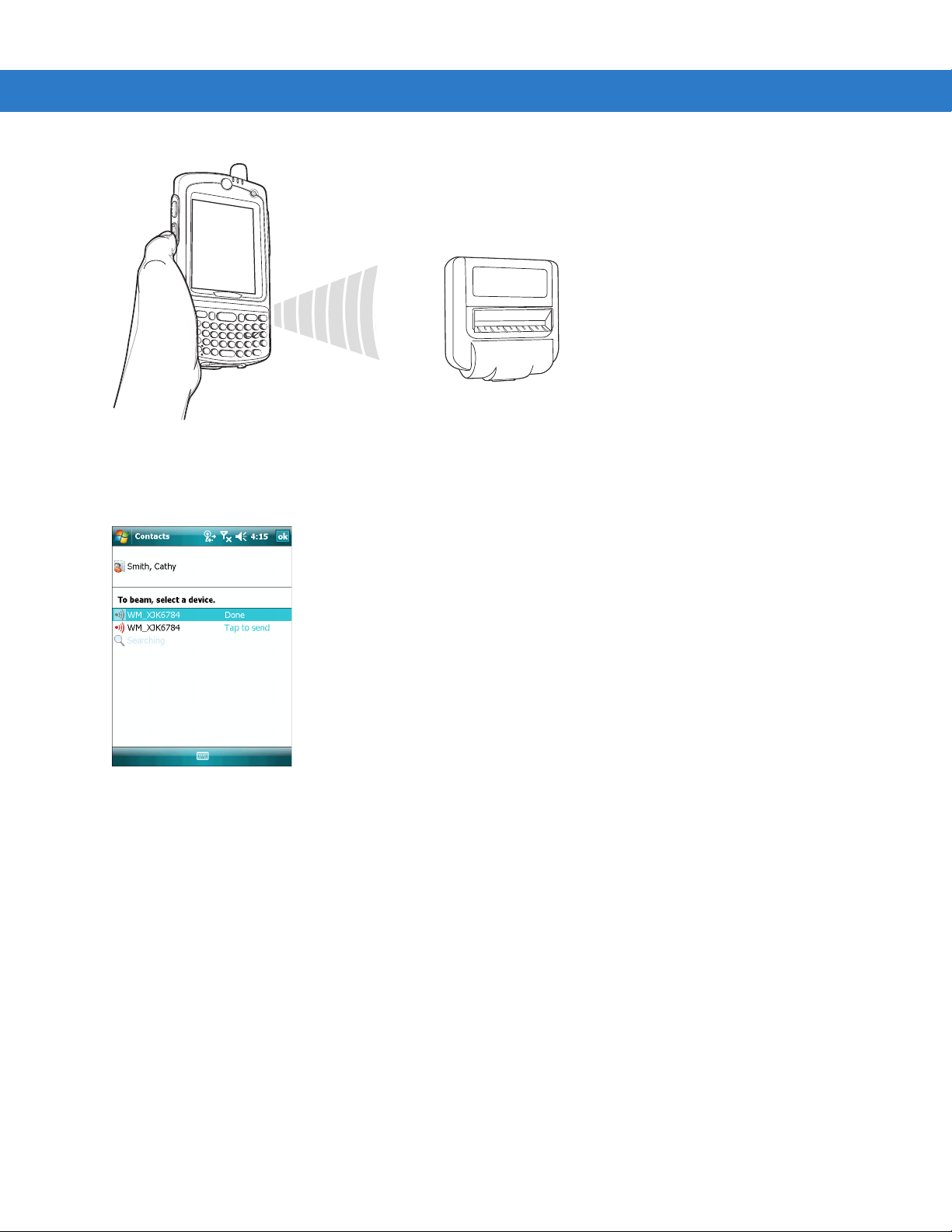
Using the MC75 2 - 41
Figure 2-28
3. Tap and hold the item, then tap Beam [type of item] on the pop-up menu.
4. Tap the device that you want to send the file to.
Figure 2-29
Align MC75 with IrDA Device
Beam Contact
To receive files via IrDA connection:
1. Align the IrDA port of the MC75 with that of the other IrDA device so that they are unobstructed and within a
close range.
2. On the other device, send the file to the MC75.
Page 76

2 - 42 MC75 User Guide
Figure 2-30
3. When the Receiving Data dialog displays, tap Yes.
Receive File
Page 77

Chapter 3 Using GPS Navigation
Introduction
The MC75 includes Global Positioning System (GPS) technology using the SiRF III chipset. GPS technology is
based on a worldwide system of GPS satellites orbiting the earth that continuously transmit digital radio signals.
These radio signals contain data on the satellites’ locations and their exact clock time and are used to determine
your location on the earth.
WARNING! When using the MC75 in a vehicle, it is the user’s responsibility to place, secure and use in a
manner that will not cause accidents, personal injury or property damage or obstruct their view. It
is the responsibility of the driver to operate the vehicle in a safe manner, maintain observation of
all driving conditions at all times, and not become distracted by the device to the exclusion of safe
driving practices. It is unsafe to operate the controls of the device while driving.
Software Installation
Third-party GPS navigation software is required. Evaluation software is available from various suppliers. For
example; VisualGPS, visit: http://www.visualgps.net/VisualGPSce/
If interested in purchasing GPS navigation software check with the GPS software vendor (before purchasing,
downloading, or ins
application’s user guide for application installation and setup information.
MC75 GPS Setup
The GPS-enabled MC75 uses Microsoft Windows Mobile 6, so the operating system automatically manages
access to the GPS receiver to allow multiple programs to simultaneously access GPS data.
By default, the MC75 has the following Settings:
1. Ta p Start > Settings > System > External GPS icon.
2. In the Programs tab, the GPS program port is set to None.
3. In the Hardware tab, the GPS hardware port is set to COM8.
talling any software) to determine that the application is compatible with the MC75. Refer to the
Page 78

3 - 2 MC75 User Guide
To access the GPS receiver from multiple programs simultaneously, the user can either use the Microsoft GPS API
or change the GPS program port setting and access the GPS program port in the multiplexed way.
Operation
Acquiring satellite signals may take a few minutes. It is best to be outside and have a clear, unobstructed view of
the sky. Without a clear view, acquisition takes much longer and could result in the MC75 being unable to compute
the initial position quickly. When operating the device indoors access to the GPS signals may be limited or
unavailable.
NOTE When using a GPS navigation application, ensure that the MC75 does not go into suspend mode. If the MC75
GPS Maps on microSD Cards
GPS navigation software vendors may sell maps on microSD cards. If using a microSD card with the GPS
navigation software:
suspends then the power to the GPS radio is removed. Upon resume the GPS receiver must reacquire a valid GPS
signal, resulting in a a delay of positional information.
1. Remove the Memory Card Cover on the side of the MC75.
2. Insert the microSD card into the slot.
3. Replace the Memory Card Cover.
Answering a Phone Call While Using GPS
If you receive a phone call while using your GPS navigation software:
1. Answer the phone call by pressing the Answer button.
2. Once you end the phone call, press the End Call button to resume the audio on the GPS software.
NOTE Anytime you are using GPS on the MC75 and you receive a phone call, the audio on the GPS navigation software
is muted until you finish the call.
Losing the GPS Signal While in a Vehicle
GPS performance on the MC75 may be affected if the vehicle has thermal glass windows and windshields, which
can block the MC75 from receiving a GPS signal from satellites. To improve GPS signal strength, place the MC75
where there is a clear view of the sky. A direct line of sight is required between the MC75 and the GPS satellites to
access information from the satellites.
The Global Positioning System (GPS) is a system that allows the us
er to track their position anywhere on the earth.
Assisted GPS
NOTE On devices with OEM version 03.38.0004, to configure the MC75 to obtain GPS data from a SUPL server see
GPS can be used in stand-alone or Assisted GPS (A-GPS) modes. A Stand-alone GPS receiver downloads data
from GPS satellites. It can take several minutes to get a fix. By using GPS Location servers, A-GPS dramatically
Assisted GPS on page C-19 for more information.
Page 79

Using GPS Navigation 3 - 3
improves the performance of the Time To First Fix (TTFF) of GPS receivers by providing them with data that they
would ordinarily have to download from the GPS satellites. With the A-GPS data, GPS receivers can operate faster
and more reliably.
A-GPS follows the Secure User Plane Location (SUPL) protocol which allows the MC75 to communicate with a
location server. Refer to the EMDK Help file for information on setting up SUPL on the MC75.
Page 80

3 - 4 MC75 User Guide
Page 81

Chapter 4 Using Bluetooth
Introduction
Bluetooth-equipped devices can communicate without wires, using frequency-hopping spread spectrum (FHSS)
radio frequency (RF) to transmit and receive data in the 2.4 GHz Industry Scientific and Medical (ISM) band
(802.15.1). Bluetooth wireless technology is specifically designed for short-range (30 feet/10 meters)
communication and low power consumption.
MC75s with Bluetooth capabilities can exchange information (e.g., files, appointments, and tasks) with other
Bluetooth enabled devices such as phones, printers, access points, and other mobile computers. To use the MC75
as a modem, create a dial-up modem connection between a computer and MC75.
Zebra mobile computers with Bluetooth technology use the StoneStreet Bluetooth stack. To program Bluetooth
within the MC75 refer to the Enterprise Mobility Developer Kit (EMDK) Help.
Adaptive Frequency Hopping
Adaptive Frequency Hopping (AFH) is a method of avoiding fixed frequency interferers, and can be used with
Bluetooth voice. All devices in the piconet (Bluetooth network) must be AFH-capable in order for AFH to work.
There is no AFH when connecting and discovering devices. Avoid making Bluetooth connections and discoveries
during critical 802.11b communications. AFH for Bluetooth consists of four main sections:
•
Channel Classification - A method of detecting an interference on a channel-by-channel basis, or pre-defined
channel mask.
•
Link Management - Coordinates and distributes the AFH information to the rest of the Bluetooth network.
•
Hop Sequence Modification - Avoids interference by selectively reducing the number of hopping channels.
•
Channel Maintenance - A method for periodically re-evaluating the channels.
When AFH is enabled, the Bluetooth radio “hops around” (instead of through) the 802.11b high-rate channels. AFH
coexistence allows Zebra mobile computers to operate in any infrastructure.
Page 82

4 - 2 MC75 User Guide
The Bluetooth radio in this MC75 operates as a Class 2 device power class. The maximum output power is 2.5mW
and the expected range is 32.8 feet (10 meters). A definition of ranges based on power class is difficult to obtain
due to power and device differences, and whether one measures open space or closed office space.
NOTE It is not recommended to perform Bluetooth wireless technology inquiry when high rate 802.11b operation is
required.
Security
The current Bluetooth specification defines security at the link level. Application-level security is not specified. This
allows application developers to define security mechanisms tailored to their specific need. Link-level security
occurs between devices, not users, while application-level security can be implemented on a per-user basis. The
Bluetooth specification defines security algorithms and procedures needed to authenticate devices, and if needed,
encrypt the data flowing on the link between the devices. Device authentication is a mandatory feature of Bluetooth
while link encryption is optional.
Pairing of Bluetooth devices is accomplishe
devices and create a link key for them. Entering a common PIN number in the devices being paired generates the
initialization key. The PIN number is never sent over the air. By default, the Bluetooth stack responds with no key
when a key is requested (it is up to user to respond to the key request event). Authentication of Bluetooth devices
is based-upon a challenge-response transaction. Bluetooth allows for a PIN number or passkey that is used to
create other 128-bit keys used for security and encryption. The encryption key is derived from the link key used to
authenticate the pairing devices. Also worthy of note is the limited range and fast frequency hopping of the
Bluetooth radios that makes long-distance eavesdropping difficult.
Recommendations are:
•
Perform pairing in a secure environment
•
Keep PIN codes private and don't store the PIN codes in the mobile computer
•
Implement application-level security.
d by creating an initialization key that is used to authenticate the
Page 83

Turning the Bluetooth Radio Mode On and Off
NOTE On devices with Windows Mobile 6.5.3, turn the Bluetooth radio on or off using the Wireless Manager. Tap the
Status bar and select the Connectivity icon. Tap Wireless Manager.
Turn off the Bluetooth radio to save power or if entering an area with radio restrictions (e.g., an airplane). When the
radio is off, other Bluetooth devices cannot see or connect to the MC75. Turn on the Bluetooth radio to exchange
information with other Bluetooth devices (within range). Communicate only with Bluetooth radios in close proximity.
NOTE To achieve the best battery life turn off radios not in use.
Disabling Bluetooth
To disable Bluetooth, tap Bluetooth icon > Disable Bluetooth. The Bluetooth icon changes to indicate that
Bluetooth is disabled.
Using Bluetooth 4 - 3
Figure 4-1
Disable Bluetooth
Enabling Bluetooth
To enable Bluetooth, tap Bluetooth icon > Enable Bluetooth. The Bluetooth icon changes to indicate that
Bluetooth is enabled.
Figure 4-2
Enable Bluetooth
Page 84

4 - 4 MC75 User Guide
Bluetooth Power States
Cold Boot
Performing a cold boot on the MC75 turns off Bluetooth after initialization (which takes a few moments). It is normal
to see the Bluetooth icon appear and disappear, as well as a wait cursor, when initialization proceeds in all modes.
Warm Boot
Performing a warm boot on the MC75 returns Bluetooth to the last state after initialization.
Suspend
Suspending the MC75 turns off Bluetooth.
NOTE If there is an active Bluetooth connection between the MC75 and another Bluetooth device, the MC75 will not
timeout. However, if the user presses the Power button on the MC75, the MC75 will suspend and upon
receiving data from a remote Bluetooth device, the MC75 will wake from suspend mode. For example,
headset redial or Bluetooth scanner sending data to the MC75.
Resume
When the MC75 resumes, Bluetooth turns on if it was on prior to suspend.
Modes
The BTExplorer application has two modes for managing Bluetooth connections: Wizard Mode and Explorer Mode.
The Wizard Mode is for novice Bluetooth users and the Explorer Mode is for experienced Bluetooth users. To
switch between modes, select View > Wizard Mode or View > Explorer Mode.
Wizard Mode
Wizard Mode provides a simple process for discovering and connecting to Bluetooth devices.
Wizard Mode shows the devices and services in a simple Favorites view created by following the step-by-step
wizard.
Explorer Mode
The Explorer Mode window is easy to navigate and provides greater control to users familiar with Bluetooth. The
menu bar provides quick access to the options and tools used to connect to devices. To access Explorer Mode, tap
View > Explorer Mode.
NOTE Switching between Wizard Mode and Explorer Mode closes all active connections.
Page 85

Using Bluetooth 4 - 5
Figure 4-3
You can also use the “tap and hold” techniq
those on the Windows desktop. The tree structure lists the following sub-items:
•
•
•
Explorer Mode Window
ue to view available options. Scroll bars and view options are similar to
Local Device - This device
Remote Device - Other Bluetooth devices
rusted Devices - Bonded (paired) Bluetooth devices
• T
• U
ntrusted Devices - Discovered devices that are not bonded
Favorites - Selected services that are set as Favorite for quick access.
NOTE Switching between Wizard Mode and Explorer Mode closes all active connections.
Page 86

4 - 6 MC75 User Guide
Discovering Bluetooth Device(s)
The MC75 can receive information from discovered devices without bonding. However, once bonded, the MC75
and a bonded device exchange information automatically when you turn the Bluetooth radio on. See Bonding with
Discovered Device(s) on page 4-20 for more information.
To find Bluetooth devices in the area:
1. Ensure that Bluetooth is enabled on both devices.
2. Ensure that the Bluetooth device to discover is in discoverable and connectable modes.
3. Ensure that the require profile is enabled on the MC75. See Profiles Tab on page 4-32 for more information.
4. Ensure that the two devices are within 30 feet (10 meters) of one another.
5. Tap the Bluetooth icon and select Show BTExplorer. The BTExplorer window appears.
NOTE If favorite connections have already been created, the Favorites screen displays. If no favorite connections
have been created, the New Connection Wizard screen displays.
6. Ta p Menu > New Connection.The New Connection Wizard appears.
Figure 4-4
7. Select Explore Services on Remote Device or another from the drop-down list and tap Next.
•
•
•
•
•
•
•
•
•
BTExplorer Window
The following actions are available in the drop-down list
Explore Services on Remote Device
Pair with a Remote Device
Active Sync via Bluetooth
Browse Files on Remote Device
Connect to Headset
Connect to Internet using Access Point
Connect to Internet using Phone/Modem
Connect to Personal Area Network
Connect to Printer
(actions may vary depending upon configurations):
Page 87

•
Send or Exchange Objects
•
Associate Serial Port.
NOTE If a device discovery action has not been previously performed, a device discovery is automatically initiated. If
a device discovery has previously been performed, the device discovery process is skipped, and the
previously found list of devices displays. To start a new device discovery, tap and hold in the window and select
Discover Devices from the pop-up menu.
8. BTExplorer searches for Bluetooth devices in the area.
Using Bluetooth 4 - 7
Figure 4-5
Figure 4-6
9. Select a device from the list and tap Next. The MC75 searches for services on the selected Bluetooth device.
Discover Devices Dialog Box
The discovered devices display in the Select
Select Remote Device Window
Remote Device window.
Page 88

4 - 8 MC75 User Guide
Figure 4-7
10. Select a service from the list and press Next. The Connection Favorite Options window appears.
Figure 4-8
11. In the Favorite Name text box, enter a name for this service that will appear in the Favorite window.
12. Ta p Next. The Connection Summary window appears.
Device Services
NOTE If the MC75 discovers a service but the service is not supported, the service icon is grayed-out.
Connection Favorite Options Window
13. Ta p Connect to add the service to the Favorite window and connect to the service.
Page 89

Using Bluetooth 4 - 9
Figure 4-9
Favorites Window
Available Services
NOTE Some devices might not require a PIN. This depends upon the device’s authentication.
The MC75 offers the following services:
•
File Transfer Services
•
Dial-Up Networking Services
•
OBEX Object Push Services
•
Headset Audio Gateway Services
•
Hands-Free Audio Gateway Services
•
Serial Port Services
•
Personal Area Networking Services
•
IrMC Services.
See the following sections for info
rmation on these services.
File Transfer Services
NOTE Shared folders are a security risk.
To transfer files between the MC75 and another Bluetooth enabled device:
1. Ensure the MC75 is discoverable and connectable. See Device Info Tab on page 4-23.
2. Ensure that OBEX File Transfer profile is enabled on the MC75. See Profiles Tab on page 4-32 for more
information.
NOTE If favorite connections have already been created, the Favorites screen displays. If no favorite connections
have been created, the New Connection Wizard screen displays.
3. Use the Connection Wizard to search for a Bluetooth device.
Page 90

4 - 10 MC75 User Guide
4. Select the device and tap Next. The Select Remote Service window appears.
5. Ta p Next. The Connection Favorite Options window appears.
6. Ta p Next. The Connection Summary window appears.
7. Ta p Connect. The remote device’s accessible folders appear.
Figure 4-10
8. Double-tap the file to copy. The Save Remote File window appears.
Figure 4-11
9. Tap and hold on the file. A pop-up menu appears.
10. Select the action to perform:
•
•
File Transfer Window
Save Remote File Window
New - create a new file or folder on the remote device
Delete - delete the selected file on the remote device.
•
Get File - copy the file from the remote device to the MC75.
•
Put File - copy a file from the MC75 to the remote device.
Creating a New File or Folder
To create a new folder or file on the remote device:
1. Tap and hold on the screen and select New > Folder or New > File. The Create New Folder or Create New
File window appears.
Page 91

Using Bluetooth 4 - 11
2. Enter the name for the new folder or file.
3. Ta p OK to create the new folder or file on the remote device.
Deleting a File
To delete a file from the remote device:
1. Tap and hold on the file to delete and select Delete.
2. In the Delete Remote Device File dialog box tap Yes.
Getting a File
To copy a file from a remote device:
1. Double-tap or tap and hold on the file and select Get. The Save Remote File window appears.
2. Navigate to the directory to save the file.
3. Ta p Save. The file is transferred from the remote device to the MC75.
Copying a File
To copy a file to a remote device:
1. Ta p Action > Put. The Send Local File window appears.
2. Navigate to the directory to save the file and select a file.
3. Ta p Open. The file copies from the MC75 to the remote device.
Connecting to the Internet Using an Access Point
This section explains how to access a Bluetooth-enabled LAN access point (AP) for a network connection. Use
Internet Explorer to connect to a server.
1. Ensure the MC75 is discoverable and connectable. See Device Info Tab on page 4-23.
2. Ensure that the Personal Area Networking profile is enabled on the MC75. See Profiles Tab on page 4-32 for
more information.
3. Use the Connection Wizard to search for a Bluetooth AP.
NOTE If favorite connections have already been created, the Favorites screen displays. If no favorite connections
have been created, the New Connection Wizard screen displays.
4.
Select the Personal Area Network or Network Access service and select Connect from the pop-up menu.
The MC75 connects with the access point.
5. Ta p Start > Internet Explorer. The Internet Explorer window appears.
6. In the address field, enter an internet address and tap the Enter button. The web page loads.
NOTE Network Access profile is not supported.
Page 92

4 - 12 MC75 User Guide
Dial-Up Networking Services
Dial-up networking allows the user to connect a PC or laptop to the MC75 and use the MC75 as a modem to
connect to an office network or ISP.
Before setting up dial-up networking, obtain dial-up informa
tion and other necessary settings (username, password
and domain name, if required) for the office network or ISP. To create a new Bluetooth connection:
1. Ensure the MC75 is discoverable and connectable. See Device Info Tab on page 4-23.
2. Ensure that the Dial-Up Networking profile is enabled on the MC75. See Profiles Tab on page 4-32 for more
information.
3. Ta p Menu > Settings > Services tab.
4. Ta p Add button.
5. Select Dial-up networking Service.
6. Ta p OK. The Edit Local Services window appears.
Figure 4-12
7. In the Local COM Port drop-down list, select DUN1 for GSM configurations or WMP9 for CDMA
Edit Local Service Window
configurations.
8. Ta p OK twice.
9. On the PC or laptop, set up Bluetooth according to the manufacturer’s instructions.
10. On the PC or laptop Bluetooth software, search for the MC75 and select the Dial-up Networking service.
11. Using dial-up software on the PC or laptop, connect to the MC75.
12. The MC75 phone function dials the ISP number and connects to the ISP.
13. To verify, on the PC or laptop, launch Internet Explorer and open a web site.
Object Exchange Push Services
Object Exchange (OBEX) is a set of protocols that allows sharing objects such as Contacts or pictures using
Bluetooth.
To exchange contact information with another Bluetooth enabled device:
1. Ensure the MC75 is discoverable and connectable. See Device Info Tab on page 4-23.
Page 93

Using Bluetooth 4 - 13
2. Ensure that the OBEX Object Push profile is enabled on the MC75. See Profiles Tab on page 4-32 for more
information.
NOTE If favorite connections have already been created, the Favorites screen displays. If no favorite connections
have been created, the New Connection Wizard screen displays.
3.
Use the Connection Wizard to search for a Bluetooth device.
4. Select the device and tap Next.
5. Select the OBEX Object Push service and select Connect. The OBEX Object Push window appears.
6. In the Action drop-down list, select one of the following options: Send Contact Information, Swap Contact
Information, Fetch Contact Information, or Send a Picture.
Sending a Contact
To send a contact to another device:
NOTE Prior to sending and receiving contacts, a default contact must be set up before attempting to send a
contact.
1.
Tap and hold on OBEX Object Push and select Connect. The OBEX Object Push window appears.
Figure 4-13
2. In the Action: drop-down list, select Send Contact Information.
3. Ta p . The Select Contact Entry window appears.
OBEX Object Push Window
Page 94
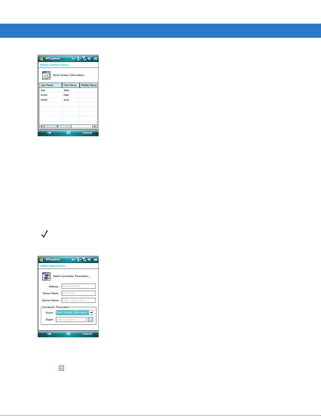
4 - 14 MC75 User Guide
Figure 4-14
4. Select a contact to send to the other device.
5. Ta p OK.
6. Ta p OK to send the contact to the other device and display a confirmation dialog box on the other device to
Select Contact Entry Window
accept the contact. A Send Contact dialog appears.
7. Ta p Ok.
Swapping Contacts
To swap contacts with another device:
NOTE Prior to swapping contacts, a default contact must be set up before attempting to send a contact.
1. Tap and hold on OBEX Object Push and select Connect. The OBEX Object Push window appears.
Figure 4-15
2. In the Action: drop-down list, select Swap Contact Information.
3. Ta p . The Select Contact Entry window appears.
OBEX Object Push Window
Page 95

Using Bluetooth 4 - 15
Figure 4-16
4. Select a contact to send to the other device.
5. Ta p OK.
6. Ta p OK to swap contacts with the other device and display a confirmation dialog box on the other device to
Select Contact Entry Window
accept the contact.
7. Ta p Ok.
Fetching a Contact
To fetch a contact from another device:
NOTE Prior to sending and receiving contacts, a default contact must be set up before attempting to send a contact.
1. Tap and hold on OBEX Object Push and select Connect. The OBEX Object Push window appears.
Figure 4-17
2. In the Action: drop-down list, select Fetch Contact information.
3. Ta p OK. The contact on the other device is copied.
OBEX Object Push Window
Sending a Picture
To send a picture to another device:
Page 96

4 - 16 MC75 User Guide
1. Tap and hold on OBEX Object Push and select Connect. The OBEX Object Push window appears.
Figure 4-18
2. In the Action: drop-down list, select Send A Picture.
3. Ta p . The Send Local Picture window appears.
Figure 4-19
4. Navigate to the picture to send to the other device.
5. Ta p Open.
OBEX Object Push Window
Send Local Picture Window
6. Ta p OK to send the picture to the other device and display a confirmation dialog box on the other device to
accept the picture. A Send Picture dialog appears.
7. Ta p Ok.
Headset Services
To connect to a Bluetooth headset:
NOTE Newer Bluetooth headsets are device dependant and remember the last device they connected to. If problems
occur while connecting to the headset, place the headset in discovery mode. Refer to the headset user manual
for more information.
1.
Ensure the MC75 is discoverable and connectable. See Device Info Tab on page 4-23.
Page 97

Using Bluetooth 4 - 17
2. Ensure that the Headset profile is enabled on the MC75. See Profiles Tab on page 4-32 for more information.
3. Use the Connection Wizard to search for a Bluetooth headset.
4. Select the device and tap Next.
5. Select the Headset service name and select Connect. The MC75 connects to the headset. Refer to the
headset user manual for instructions on communicating with a Bluetooth device.
NOTE When using a Bluetooth headset with Headset Services, you cannot accept or end a call from the headset.
You must accept or end a call on the MC75.
6.
Press the communication button on the headset. This routes both system and WAN call audio to the headset.
7. When a call is received on the MC75, tap the Accept button to answer the call.
8. Press the communication button on the headset to route the audio back to the MC75.
NOTE If a wired headset is connected to the MC75, the Bluetooth headset connection is disconnected.
Hands-free Services
To connect to a Bluetooth headset:
NOTE Newer Bluetooth headsets are device dependant and remember the last device they connected to. If problems
occur while connecting to the headset, place the headset in discovery mode. Refer to the headset user manual
for more information.
Only WAN audio is routed to the headset. System au
You can accept calls and re-dial using the Hands-free profile.
Hands-free profile does not support 3-way calling.
Ensure the MC75 is discoverable and connectable. See Device Info Tab on page 4-23.
1.
2. Ensure that the Hands Free profile is enabled on the MC75. See Profiles Tab on page 4-32 for more
dio is still emitted through the MC75 speaker.
information.
3. Use the Connection Wizard to search for a Bluetooth hands-free headset.
4. Select the hand-free device and tap Next.
5. Select the Hands-free service name and select Connect. The MC75 connects to the headset. Refer to the
headset user manual for instructions on communicating with a Bluetooth device.
6. During an active connection, the MC75 cannot go into suspend mode when the Power Button is pressed. A
message appears notifying the user.
Once the WAN call is disconnected (with Hands-free profile) the Power button is enabled.
Page 98

Headset icon
4 - 18 MC75 User Guide
Figure 4-20
WWAN Bluetooth Audio Notification Dialog Box
Serial Port Services
Use the wireless Bluetooth serial port connection as you would a physical serial cable connection. Configure the
application that will use the connection to the correct serial port.
To establish a serial port connection:
1. Ensure the MC75 is discoverable and connectable. See Device Info Tab on page 4-23.
2. Use the Connection Wizard to search for a Bluetooth serial device.
3. Select the device and tap Next. The Connection Favorite Options window appears.
4. In the Local COM Port: drop-down list select a COM port.
5. Ta p Finish.
ActiveSync Using Serial Port Services
NOTE By default, COM ports COM5, COM9, COM11, COM21, COM22 and COM23 are Bluetooth virtual ports. If an
application opens one of these ports, the Bluetooth driver activates and guides you through a Bluetooth
connection.
Use the wireless Bluetooth serial port connection for ActiveSync just as you would a physical serial cable
connection. You must configure the application that will use the connection to the correct serial port.
Page 99

Using Bluetooth 4 - 19
Figure 4-21
ActiveSync Connection Settings Window on PC
To establish an ActiveSync connection:
1. Ensure the MC75 is discoverable and connectable. See Device Info Tab on page 4-23.
2. Ensure that the Sync profile is enabled on the MC75. See Profiles Tab on page 4-32 for more information.
3. Use the Connection Wizard to search for a Bluetooth device, such as a PC. In the drop-down list select
ActiveSync via Bluetooth.
4. Select the device and tap Next. The Connection Favorite Options window appears.
5. Ta p Connect. The Remote Service Connection window appears.
Figure 4-22
6. In the Service Type drop-down list, select Active Sync.
7. Ta p OK. The MC75 connects the PC and an ActiveSync session begins.
8. Ta p Finish. The Connection Favorite Options window appears.
9. To end the session, tap the ActiveSync icon in the Favorite window and select Disconnect from the pop-up
Remote Service Connection Window
window.
Page 100

4 - 20 MC75 User Guide
Personal Area Network Services
NOTE This profile supports Ad-hoc and PAN User. Network Access Profile is not supported.
Connect two or more Bluetooth devices to share files, collaborate, or play multi-player games. To establish a
Personal Area Network connection:
1. Ensure the MC75 is discoverable and connectable. See Device Info Tab on page 4-23.
2. Ensure that the Personal Area Networking profile is enabled on the MC75. See Profiles Tab on page 4-32 for
more information.
3. Use the Connection Wizard to search for a Bluetooth device.
4. Select the device and tap Next. The Connection Favorite Options window appears.
5. Ta p Next. The Connection Summary window appears.
6. Ta p Connect. The MC75 connects to the Bluetooth device.
IrMC Synchronization Services
IrMC Synchronization is used to synchronize PIM contacts between a remote device and the MC75. To establish
an IrMC synchronization:
1. Ensure the MC75 is discoverable and connectable. See Device Info Tab on page 4-23.
2. Ensure that the Sync profile is enabled on the MC75. See Profiles Tab on page 4-32 for more information.
3. Ta p Menu > Settings > Services tab.
4. Ta p Add button.
5. Select IrMC Synchronization.
6. Ta p OK. The Edit Local Services window appears.
7. Ta p OK twice.
8. Use the Connection Wizard to search for a Bluetooth device, such as a Car Kit.
9. Select the device and tap Next. The Connection Favorite Options window appears.
10. Tap and hold IrMA Synchronization and select Connect in the pop-up menu.
NOTE To automatically transfer contact with a Car Kit, ensure that the IrMC Synchronization service is enabled on
the MC75.
Bonding with Discovered Device(s)
A bond is a relationship created between the MC75 and another Bluetooth device in order to exchange information
in a secure manner. Creating a bond involves entering the same PIN on the two devices. After creating a bond and
turning on the Bluetooth radios, the devices recognize the bond and can exchange information without re-entering
a PIN.
 Loading...