


MC67 with Android OS
MN000116A04
Mobile Computer
Integrator Guide


MC67 with Android™ OS
Integrator Guide
MN000116A04
Rev A
May 2019

ii MC67 with Android™ OS Integrator Guide
No part of this publication may be reproduced or used in any form, or by any electrical or mechanical means,
without permission in writing from Zebra. This includes electronic or mechanical means, such as photocopying,
recording, or information storage and retrieval systems. The material in this manual is subject to change
without notice.
The software is provided strictly on an “as is” basis. All software, including firmware, furnished to the user is on
a licensed basis. Zebra grants to the user a non-transferable and non-exclusive license to use each software
or firmware program delivered hereunder (licensed program). Except as noted below, such license may not be
assigned, sublicensed, or otherwise transferred by the user without prior written consent of Zebra. No right to
copy a licensed program in whole or in part is granted, except as permitted under copyright law. The user shall
not modify, merge, or incorporate any form or portion of a licensed program with other program material, create
a derivative work from a licensed program, or use a licensed program in a network without written permission
from Zebra. The user agrees to maintain Zebra’s copyright notice on the licensed programs delivered
hereunder, and to include the same on any authorized copies it makes, in whole or in part. The user agrees not
to decompile, disassemble, decode, or reverse engineer any licensed program delivered to the user or any
portion thereof.
Zebra reserves the right to make changes to any software or product to improve reliability, function, or design.
Zebra does not assume any product liability arising out of, or in connection with, the application or use of any
product, circuit, or application described herein.
No license is granted, either expressly or by implication, estoppel, or otherwise under any Zebra Technologies
Corporation, intellectual property rights. An implied license only exists for equipment, circuits, and subsystems
contained in Zebra products.

Revision History
Changes to the original manual are listed below:
Change Date Description
A01 Rev. A 1/2014 Initial release.
A02 Rev. A 5/2015 Rebranding.
A03 Rev. A 5/2016 Add Android KitKat support.
A03 Rev. B 4/2017 Add caution in section Update the System on page 7-6.
A04 Rev. A 3/2019 Update cleaning procedures.
iii

iv MC67 with Android™ OS Integrator Guide

TABLE OF CONTENTS
Revision History .......................................................................................................................................iii
Table of Contents
About This Guide
Introduction ...................................................................................................................................... xiii
Documentation Set .......................................................................................................................... xiii
Configurations.................................................................................................................................. xiii
Software Versions............................................................................................................................ xiv
Notational Conventions.................................................................................................................... xiv
Icon Conventions ............................................................................................................................. xiv
Related Documents ......................................................................................................................... xv
Service Information .......................................................................................................................... xv
Chapter 1: Getting Started
Setup .............................................................................................................................................. 1-1
Installing the SIM Card ............................................................................................................. 1-1
Installing the Battery ................................................................................................................. 1-2
Charging the Battery ................................................................................................................ 1-3
LED Charging Indicators .......................................................................................................... 1-4
Powering On the MC67 ............................................................................................................ 1-4
Replacing the Battery ..................................................................................................................... 1-4
Replacing the microSD Card ......................................................................................................... 1-5
Replacing the SIM Card ................................................................................................................. 1-6
Resetting the MC67 ....................................................................................................................... 1-7
Performing a Soft Reset ........................................................................................................... 1-7
Performing a Hard Reset ......................................................................................................... 1-7
Performing an Enterprise Reset ............................................................................................... 1-8
Performing a Factory Reset ..................................................................................................... 1-8

vi MC67 with Android™ OS Integrator Guide
Chapter 2: Accessories
Accessories .................................................................................................................................... 2-1
Single Slot USB Cradle .................................................................................................................. 2-4
Setup ........................................................................................................................................ 2-4
Charging the MC67 Battery ...................................................................................................... 2-4
Charging the Spare Battery ...................................................................................................... 2-5
Battery Charging ...................................................................................................................... 2-5
Charging Temperature ....................................................................................................... 2-6
Four Slot Ethernet Cradle .............................................................................................................. 2-7
CRD5501-4001ER Setup ......................................................................................................... 2-7
Daisy Chaining Ethernet Cradles ....................................................................................... 2-8
LED Indicators (CRD5501-4001ER) .................................................................................. 2-8
Ethernet Settings ...................................................................................................................... 2-8
Configuring Ethernet Proxy Settings .................................................................................. 2-9
Configuring Ethernet Static IP Address .............................................................................. 2-9
Charging the MC67 ................................................................................................................ 2-10
Charging Temperature ..................................................................................................... 2-11
Four Slot Charge Only Cradle ...................................................................................................... 2-12
Setup ...................................................................................................................................... 2-12
Charging the MC67 .......................................................................................................... 2-12
Wall Mount Bracket ...................................................................................................................... 2-13
Mounting a Four Slot Cradle .................................................................................................. 2-13
VCD5500 Vehicle Cradle ............................................................................................................. 2-15
Requirements ......................................................................................................................... 2-15
Connector Pin-Outs ................................................................................................................ 2-15
Mounting the Cradle ............................................................................................................... 2-16
Power Connection .................................................................................................................. 2-16
Charging the MC67 Battery .................................................................................................... 2-18
Removing the MC67 .............................................................................................................. 2-18
Charging the MC67 ................................................................................................................ 2-19
Charging Temperature ..................................................................................................... 2-19
Four Slot Battery Charger ............................................................................................................ 2-20
Spare Battery Charging .......................................................................................................... 2-20
Battery Charging Indicators .................................................................................................... 2-20
Charging Temperature ..................................................................................................... 2-20
Cables .......................................................................................................................
USB Charging Cable .............................................................................................................. 2-21
Charge Only Cable ................................................................................................................. 2-22
Auto Charge Cable ................................................................................................................. 2-22
Connecting Cables to the MC67 ............................................................................................ 2-22
Charging the MC67 ................................................................................................................ 2-23
Charging Temperature ..................................................................................................... 2-23
Vehicle Holder .............................................................................................................................. 2-24
Installation Reminders ............................................................................................................ 2-24
Device Mounting Precautions ................................................................................................ 2-24
Installation .............................................................................................................................. 2-25
Assembly .......................................................................................................................... 2-25
Windshield Installation ..................................................................................................... 2-25
Flat Surface Installation .................................................................................................... 2-26
Hand Strap Replacement ............................................................................................................. 2-28
................... 2-21

Table of Contents vii
Removal ................................................................................................................................. 2-28
Installation .............................................................................................................................. 2-29
Chapter 3: USB Communication
Connecting to a Host Computer via USB ....................................................................................... 3-1
Connecting to the MC67 as a Media Device ............................................................................ 3-1
Connecting to the MC67 as an Installer ................................................................................... 3-1
Disconnect from the Host Computer .............................................................................................. 3-2
Chapter 4: DataWedge Configuration
Basic Scanning .............................................................................................................................. 4-1
Using the Imager ...................................................................................................................... 4-1
Using the Camera .................................................................................................................... 4-1
Profiles ........................................................................................................................................... 4-2
Profile0 ..................................................................................................................................... 4-3
Plug-ins .......................................................................................................................................... 4-3
Input Plug-ins ........................................................................................................................... 4-3
Process Plug-ins ...................................................................................................................... 4-3
Output Plug-ins ........................................................................................................................ 4-4
Profiles Screen ............................................................................................................................... 4-4
Profile Context Menu ................................................................................................................ 4-5
Options Menu ........................................................................................................................... 4-5
Disabling DataWedge .............................................................................................................. 4-5
Creating a New Profile ................................................................................................................... 4-6
Profile Configuration ...................................................................................................................... 4-6
Data Capture Plus .................................................................................................................... 4-7
Bar Code Input ......................................................................................................................... 4-8
Enabled .............................................................................................................................. 4-8
Scanner Selection .............................................................................................................. 4-8
Decoders ............................................................................................................................ 4-9
Decoder Params ................................................................................................................ 4-9
Decode Lengths ............................................................................................................... 4-14
UPC EAN Params ............................................................................................................ 4-15
Reader Params ................................................................................................................ 4-17
Scan Params .................................................................................................................... 4-18
MSR Input .............................................................................................................................. 4-19
Keystroke Output ................................................................................................................... 4-19
Intent Output ................................................................................................................
Intent Overview ................................................................................................................ 4-21
IP Output ................................................................................................................................ 4-22
Usage ............................................................................................................................... 4-23
Using IP Output with IPWedge ......................................................................................... 4-24
Using IP Output without IPWedge .................................................................................... 4-25
Generating Advanced Data Formatting Rules ............................................................................. 4-26
Configuring ADF Plug-in ........................................................................................................ 4-26
Creating a Rule ................................................................................................................ 4-27
Defining a Rule ................................................................................................................. 4-27
Defining Criteria ............................................................................................................... 4-27
.......... 4-20

viii MC67 with Android™ OS Integrator Guide
Defining an Action ............................................................................................................ 4-28
Deleting a Rule ................................................................................................................. 4-29
Order Rules List ............................................................................................................... 4-29
ADF Example ......................................................................................................................... 4-31
DataWedge Settings .................................................................................................................... 4-34
Importing a Configuration File ................................................................................................ 4-34
Exporting a Configuration File ................................................................................................ 4-34
Importing a Profile File ........................................................................................................... 4-35
Exporting a Profile .................................................................................................................. 4-35
Restoring DataWedge ............................................................................................................ 4-35
Configuration and Profile File Management ................................................................................. 4-36
Enterprise Folder .................................................................................................................... 4-36
Auto Import ............................................................................................................................. 4-36
Programming Notes ..................................................................................................................... 4-36
Overriding Trigger Key in an Application ................................................................................ 4-36
Capture Data and Taking a Photo in the Same Application ................................................... 4-37
Disable DataWedge on MC67 and Mass Deploy ................................................................... 4-37
Soft Scan Feature .................................................................................................................. 4-37
Sample ............................................................................................................................. 4-37
Chapter 5: Administrator Utilities
Required Software ......................................................................................................................... 5-1
On-device Application Installation .................................................................................................. 5-1
Multi-user/AppLock Configuration .................................................................................................. 5-2
Enterprise Administrator Application .............................................................................................. 5-2
Creating Users ......................................................................................................................... 5-2
Adding Packages ..................................................................................................................... 5-3
Creating Groups ....................................................................................................................... 5-4
Creating Remote Authentication .............................................................................................. 5-4
Save Data ................................................................................................................................ 5-5
Exporting File ........................................................................................................................... 5-5
Importing User List ................................................................................................................... 5-6
Importing Group List ................................................................................................................. 5-6
Importing Package List ............................................................................................................. 5-6
Editing a User ........................................................................................................................... 5-6
Deleting a User ........................................................................................................................ 5-6
Editing a Group ........................................................................................................................ 5-7
Deleting a Group ...................................................................................................................... 5-7
Editing a Package .................................................................................................................... 5-7
Deleting a Package .................................................................................................................. 5-7
MultiUser Administrator .................................................................................................................. 5-7
Importing a Password .............................................................................................................. 5-7
Disabling the Multi-user Feature .............................................................................................. 5-8
Enabling Remote Authentication .............................................................................................. 5-9
Disabling Remote Authentication ............................................................................................. 5-9
Enabling Data Separation ........................................................................................................ 5-9
Disabling Data Separation ....................................................................................................... 5-9
Delete User Data .................................................................................................................... 5-10
Capturing a Log File ............................................................................................................... 5-10

Table of Contents ix
AppLock Administrator ................................................................................................................. 5-10
Enabling Application Lock ...................................................................................................... 5-11
Disabling Application Lock ..................................................................................................... 5-11
Manual File Configuration ............................................................................................................ 5-11
Groups File ............................................................................................................................. 5-11
White List File ......................................................................................................................... 5-11
Package List File .................................................................................................................... 5-12
Groups File ............................................................................................................................. 5-12
White List File ......................................................................................................................... 5-13
Determining Applications Installed on the Device .................................................................. 5-14
Package List File .................................................................................................................... 5-14
Secure Storage ............................................................................................................................ 5-14
Installing a Key ....................................................................................................................... 5-15
Viewing Key List ..................................................................................................................... 5-15
Deleting a Key ........................................................................................................................ 5-15
Volumes ................................................................................................................................. 5-16
Creating Volume Using EFS File ..................................................................................... 5-16
Creating a Volume Manually ............................................................................................ 5-16
Mounting a Volume .......................................................................................................... 5-16
Listing Volumes ................................................................................................................ 5-17
Unmounting a Volume ...................................................................................................... 5-17
Deleting a Volume ............................................................................................................ 5-17
Encrypting an SD Card .................................................................................................... 5-17
Creating an EFS File .............................................................................................................. 5-17
Off-line Extraction Tool ........................................................................................................... 5-18
Usage ............................................................................................................................... 5-18
Usage ............................................................................................................................... 5-18
Creating an Image ............................................................................................................ 5-19
Mounting an Image .......................................................................................................... 5-19
Unmounting an Image ...................................................................................................... 5-20
Chapter 6: Settings
Location Settings ........................................................................................................................... 6-1
Screen Unlock Settings .................................................................................................................. 6-2
Single User Mode ..................................................................................................................... 6-2
Set Screen Unlock Using PIN ............................................................................................ 6-3
Set Screen Unlock Using Password ..............................
Set Screen Unlock Using Pattern ....................................................................................... 6-4
Multiple User Mode .................................................................................................................. 6-5
Passwords ..................................................................................................................................... 6-5
Button Remapping ......................................................................................................................... 6-5
Remapping a Button ................................................................................................................ 6-5
Exporting a Configuration File .................................................................................................. 6-6
Importing a Configuration File .................................................................................................. 6-7
Creating a Remap File ............................................................................................................. 6-7
Enterprise Reset ...................................................................................................................... 6-8
Accounts ........................................................................................................................................ 6-9
Language Usage ............................................................................................................................ 6-9
Changing the Language Setting ............................................................................................... 6-9
.................................................... 6-3

x MC67 with Android™ OS Integrator Guide
Adding Words to the Dictionary ................................................................................................ 6-9
Keyboard Settings .......................................................................................................................... 6-9
About Device ................................................................................................................................ 6-10
Chapter 7: Application Deployment
Security .......................................................................................................................................... 7-1
Secure Certificates ................................................................................................................... 7-1
Installing a Secure Certificate .................................................................................................. 7-1
Configuring Credential Storage Settings .................................................................................. 7-2
Development Tools ........................................................................................................................ 7-2
ADB USB Setup ............................................................................................................................. 7-3
Application Installation ................................................................................................................... 7-3
Installing Applications Using the USB Connection ................................................................... 7-3
Installing Applications Using a microSD Card .......................................................................... 7-4
Installing Applications Using the Android Debug Bridge .......................................................... 7-5
Uninstalling an Application ....................................................................................................... 7-5
Updating the System ...................................................................................................................... 7-6
Storage .......................................................................................................................................... 7-7
Random Access Memory ......................................................................................................... 7-7
External Storage ...................................................................................................................... 7-7
Internal Storage ........................................................................................................................ 7-8
Enterprise Folder ...................................................................................................................... 7-9
Application Management ............................................................................................................... 7-9
Viewing Application Details ...................................................................................................... 7-9
Stopping an Application ......................................................................................................... 7-10
Changing Application Location ............................................................................................... 7-11
Managing Downloads ............................................................................................................. 7-11
RxLogger ..................................................................................................................................... 7-11
RxLogger Configuration ......................................................................................................... 7-12
Main Log Plug-in .............................................................................................................. 7-12
Snapshot Plug-in .............................................................................................................. 7-13
Logcat Plug-in .................................................................................................................. 7-14
PushPullClient Plug-in ...................................................................................................... 7-14
TCPDump Plug-in ............................................................................................................ 7-15
ANR Plugin ....................................................................................................................... 7-15
Kernal Plug-in ................................................................................................................... 7-15
Configuration File ...........................................................................................................
Enabling Logging ................................................................................................................... 7-16
Disabling Logging ................................................................................................................... 7-16
Extracting Log Files ................................................................................................................ 7-16
.. 7-16
Chapter 8: Maintenance and Troubleshooting
Maintaining the MC67 .................................................................................................................... 8-1
Battery Safety Guidelines .............................................................................................................. 8-2
Cleaning Instructions ..................................................................................................................... 8-2
Approved Cleanser Active Ingredients ..................................................................................... 8-3
Harmful Ingredients .................................................................................................................. 8-3
Cleaning Instructions ................................................................................................................ 8-3

Table of Contents xi
Special Cleaning Notes ............................................................................................................ 8-3
Cleaning Materials Required .................................................................................................... 8-3
Cleaning Frequency ................................................................................................................. 8-3
Approved Cleanser Active Ingredients ..................................................................................... 8-3
Harmful Ingredients .................................................................................................................. 8-4
Cleaning Instructions ................................................................................................................ 8-4
Special Cleaning Notes ............................................................................................................ 8-4
Cleaning Materials Required .................................................................................................... 8-4
Cleaning the MC67 .................................................................................................................. 8-4
Housing .............................................................................................................................. 8-4
Display ............................................................................................................................... 8-4
Camera andExit Window .................................................................................................... 8-4
Housing .............................................................................................................................. 8-4
Display ............................................................................................................................... 8-5
Camera Window ................................................................................................................. 8-5
Connector Cleaning ........................................................................................................... 8-5
Cleaning Cradle Connectors .................................................................................................... 8-5
Cleaning Frequency ................................................................................................................. 8-6
Troubleshooting ............................................................................................................................. 8-6
MC67 ........................................................................................................................................ 8-6
Single Slot USB Cradle ............................................................................................................ 8-8
Four Slot Ethernet Cradle ........................................................................................................ 8-9
Vehicle Cradle ........................................................................................................................ 8-10
Four Slot Battery Charger ...................................................................................................... 8-11
Cables .................................................................................................................................... 8-11
Magnetic Stripe Reader ......................................................................................................... 8-12
Chapter A: Technical Specifications
MC67 Technical Specifications ..................................................................................................... A-1
MC67 ....................................................................................................................................... A-1
SE4500–SR Decode Zone ...................................................................................................... A-4
MC67 External Connector Pin-Outs ........................................................................................ A-7
MC67 Accessory Specifications .................................................................................................... A-7
Single Slot USB Cradle ........................................................................................................... A-7
Four Slot Battery Charger ....................................................................................................... A-8
Four Slot Charge Only Cradle ................................................................................................. A-9
Four Slot Ethernet Cradle .....................................
Magstripe Reader .................................................................................................................. A-10
Vehicle Cradle ....................................................................................................................... A-10
Cables ................................................................................................................................... A-11
Appendix B: Keypad Remap Strings
Keypad Remap Strings ................................................................................................................. B-1
Index
.................................................................. A-9

xii MC67 with Android™ OS Integrator Guide

ABOUT THIS GUIDE
Introduction
This guide provides information about using the MC67 mobile computer and accessories.
NOTE Screens and windows pictured in this guide are samples and can differ from actual screens.
Documentation Set
The documentation set for the MC67 provides information for specific user needs, and includes:
•
MC67 Quick Start Guide - describes how to get the MC67 up and running.
•
MC67 User Guide - describes how to use the MC67.
•
MC67 Integrator Guide - describes how to set up the MC67 and accessories.
Configurations
This guide covers the following configurations:
Configuration Radios Display Memory
MC67NA WLAN: 802.11
a/b/g/n
WPAN: Bluetooth
v2.1 EDR
WWAN:GSM/UMTS
GPS: Stand-alone
GPS or A-GPS
3.5” VGA
Color
1 GB RAM /
8 GB Flash
Data Capture
Options
2D imager and
camera
Operating
System
Android-based,
Android
Open-Source
Project 4.1.1
(Jelly Bean) or
4.4.4 (KitKat).
Keypads
Numeric,
QWERTY,
QWERTZ,
AZERTY or
DSD

xiv MC67 with Android™ OS Integrator Guide
Software Versions
To determine the current software versions touch or > About phone.
•
Model number- Displays the model number.
•
Android version - Displays the operating system version.
•
Kernel version - Displays the kernel version number.
•
Build number - Displays the software build number.
To determine the device serial number touch or > About phone > Status.
•
Serial number - Displays the serial number.
Notational Conventions
The following conventions are used in this document:
•
Italics are used to highlight the following:
•
Chapters and sections in this and related documents
•
Icons on a screen.
•
Bold text is used to highlight the following:
•
Dialog box, window, and screen names
•
Drop-down list and list box names
•
Check box and radio button names
•
Button names on a screen.
•
Bullets (•) indicate:
•
Action items
•
Lists of alternatives
•
Lists of required steps that are not necessarily sequential
•
Sequential lists (for example, lists that describe step-by-step procedures) appear as numbered lists.
Icon Conventions
The documentation set is designed to give the reader more visual clues. The following graphic icons are used
throughout the documentation set. These icons and their associated meanings are described below.
WARNING! The word WARNING with the associated safety icon implies information that, if disregarded,
could result in death or serious injury, or serious product damage.
CAUTION The word CAUTION with the associated safety icon implies information that, if disregarded, may result
in minor or moderate injury, or serious product damage.

NOTE NOTE contains information more important than the surrounding text, such as exceptions or
preconditions. They also refer the reader elsewhere for additional information, remind the reader how to
complete an action (when it is not part of the current procedure, for instance), or tell the reader where
something is located on the screen. There is no warning level associated with a note.
Related Documents
•
MC67 Quick Start Guide, p/n MN000114Axx.
•
MC67 Regulatory Guide, p/n MN000149Axx.
•
MC67 User Guide, p/n MN000115Axx.
•
MC67 User Guide for AOSP 4.4.4, p/n MN002642Axx.
•
Mobility Services Platform User Guide, p/n 72E-100158-xx.
For the latest version of this guide and all guides, go to: http://www.zebra.com/support.
About This Guide xv
Service Information
If you have a problem with the equipment, contact Customer Support in the region. Contact information is available
at: http://www.zebra.com/support.
When contacting support, please have the following information available:
•
Serial number of the unit (found on manufacturing label)
•
Model number or product name (found on manufacturing label)
•
Software type and version number
•
IMEI number
Customer Support responds to calls by email or telephone within the time limits set forth in support agreements.
If the problem cannot be solved by Customer Support, the user may need to return the equipment for servicing and
will be given specific directions. We are not responsible for any damages incurred during shipment if the approved
shipping container is not used. Shipping the units improperly can possibly void the warranty. Remove the SIM card
and/or microSD card from the device before shipping for service.
If the device was purchased from a business partner, contact that business partner for support.

xvi MC67 with Android™ OS Integrator Guide

CHAPTER 1 GETTING STARTED
This chapter provides information for getting the device up and running for the first time.
Setup
Perform this procedure to start using the MC67 for the first time.
1. Install the subscriber identification module (SIM) card.
2. Install the battery.
3. Charge the MC67.
4. Power on the MC67.
Installing the SIM Card
Global System for Mobile communications (GSM) phone service requires a SIM card. Obtain the card from a
service provider. The card fits into the MC67 and can contain the following information:
•
Mobile phone service provider account details
•
Information regarding service access and preferences
•
Contact information, which can be moved to Contacts on the MC67
•
Any additional subscribed services.
NOTE For more information about SIM cards, refer to the service provider's documentation.
1. To install the SIM card, lift rubber access door.
2. Slide the SIM card holder up to unlock.
3. Lift the SIM card holder door.

1 - 2 MC67 with Android™ OS Integrator Guide
Figure 1-1 Lifting the SIM Cover
4. Insert the SIM card, as shown in Inserting the SIM Card ensuring that the card slides into the holding tabs on
each side of the door.
Figure 1-2 Inserting the SIM Card
5. Close the SIM card holder door and slide down to lock into place.
6. Close the rubber access door.
7. Install the battery.
Installing the Battery
1. Insert the battery, bottom first, into the battery compartment in the back of the MC67.
2. Press the battery down into the battery compartment until the battery release latch snaps (two clicks) into
place.
NOTE If the battery has significant charge, the MC67 turns on.
3. Replace the hand strap.

Getting Started 1 - 3
1
2
Figure 1-3 Inserting the Battery
Charging the Battery
Before using the MC67 for the first time, charge the main battery until the amber Charging/Battery Status light
emitting diode (LED) remains lit. To charge the MC67, use a cable or a cradle with the appropriate power supply.
For information about the accessories available for the MC67, see Chapter 2, Accessories for more information.
The MC67 is equipped with a backup battery which automatically charges from the fully-charged main battery.
When using the MC67 for the first time, the backup battery requires approximately 40 hours to fully charge. This is
also true any time the backup battery is discharged, which occurs when the main battery is removed for several
hours. The backup battery retains random access memory (RAM) data in memory for at least 10 minutes (at room
temperature) when the MC67’s main battery is removed. When the MC67 reaches a very low battery state, the
combination of main battery and backup battery retains RAM data in memory for at least 36 hours.
For cable and cradle setup and charging procedures refer to the MC67 Integrator Guide.
•
USB Charging Cable
•
Charge Only Cable
•
Single Slot USB Cradle
•
Four Slot Charge Only Cradle
•
Four Slot Ethernet Cradle.
Charge batteries in temperatures from 0 °C to 40 °C (32 °F to 104 °F). Note that charging is intelligently controlled
by the MC67. To accomplish this, for small periods of time, the MC67 or accessory alternately enables and
disables battery charging to keep the battery at acceptable temperatures. The MC67 or accessory indicates when
charging is disabled due to abnormal temperatures via its LED.
1. To charge the main battery, connect the charging accessory to the appropriate power source.
2. Insert the MC67 into a cradle or attach to a cable. The MC67 turns on and begins charging. The
Charging/Battery Status LED blinks amber while charging, then turns solid amber when fully charged.

1 - 4 MC67 with Android™ OS Integrator Guide
LED Charging Indicators
Table 1-1 LED Charging Indicators
Charging/Battery Status
LED
Off MC67 is not charging. MC67 is not inserted correctly in the cradle or connected to
a power source. Charger/cradle is not powered.
Slow Blinking Amber (1 blink
every 2 seconds)
Solid Amber Charging complete. Note: When the battery is initially inserted in the MC67, the
Fast Blinking Amber (2
blinks/second)
MC67 is charging.
amber LED flashes once if the battery power is low or the battery is not fully
inserted.
Charging error, e.g.:
•
Temperature is too low or too high.
•
Charging has gone on too long without completion (typically eight hours).
Indication
Powering On the MC67
NOTE If during installation of the battery, the battery has significant charge, the MC67 turns on automatically.
1. Press the Power button to turn on the MC67.
The splash screen displays for about a minute as the MC67 initializes its flash file system.
Replacing the Battery
To replace the battery:
1. If the MC67 is in a cradle, remove it before performing a Safe Battery Swap.
2. Unclip the hand strap.
3. Press and hold the Power button until the menu appears.
Figure 1-4 Power Button Menu

4. Touch Battery swap. The red Data Capture LED turns on.
1
2
5. Wait for the red Data Capture LED to turn off.
6. Slide the battery latch to the right. The battery ejects slightly.
Figure 1-5 Slide Latch to the Right
7. Lift the battery from the MC67.
Getting Started 1 - 5
Figure 1-6 Lift the Battery
8. Insert the replacement battery, bottom first, into the battery compartment in the back of the MC67.
9. Press the battery down until the battery release latch snaps (two clicks) into place.
10. Replace the hand strap.
11. Press the Power button to wake the MC67.
Replacing the microSD Card
To replace the microSD card:
1. If the MC67 is in a cradle, remove it before performing a Safe Battery Swap.
2. Unclip the hand strap.
3. Press and hold the Power button until the menu appears.
4. Touch Battery swap.

1 - 6 MC67 with Android™ OS Integrator Guide
Figure 1-7 Power Button Menu
5. Wait for the red Data Capture LED to turn off.
6. Remove the battery.
7. Lift the rubber access door.
8. Slide SIM card holder door up to unlock.
9. Lift SIM Card holder door.
10. Lift the microSD card holder door.
11. Remove microSD card from holder.
12. Close microSD card holder door.
13. Close SIM card holder door.
14. Slide SIM card holder door down to lock into place.
15. Close the rubber access door.
16. Insert the battery, bottom first, into the battery compartment in the back of the MC67.
17. Press the battery down until the battery release latch snaps (two clicks) into place.
18. Replace the hand strap.
19. Press the Power button to wake the MC67.
20. If a SIM card is installed, perform a soft reset.
See Performing a Soft Reset on page 1-7.
Replacing the SIM Card
To replace the SIM card:
1. If the MC67 is in a cradle, remove it before performing a Safe Battery Swap.
2. Unclip the hand strap.
3. Press and hold the Power button until the menu appears.
4. Touch Battery swap.
5. Wait for the red Data Capture LED to turn off.

6. Remove the battery.
7. Lift the rubber access door.
8. Slide SIM card holder door up to unlock.
9. Lift the SIM Card holder door.
10. Remove SIM card from holder.
11. Close SIM card holder door.
12. Slide SIM card holder door down to lock into place.
13. Close the rubber access door.
14. Insert the battery, bottom first, into the battery compartment in the back of the MC67.
15. Press the battery down until the battery release latch snaps (two clicks) into place.
16. Replace the hand strap.
17. Perform a soft reset.
See Performing a Soft Reset on page 1-7.
Getting Started 1 - 7
Resetting the MC67
There are four reset functions:
•
Soft reset
•
Hard reset
•
Enterprise reset
•
Factory reset.
Performing a Soft Reset
Perform a soft reset if applications stop responding.
1. Press and hold the Power button until the menu appears.
2. Touch Reset.
3. The device reboots.
Performing a Hard Reset
CAUTION Performing a hard reset with a SIM card installed in the MC67 may cause damage or data corruption to the
SIM card.
Perform a hard reset if the MC67 stops responding.
1. On a numeric or DSD keypad, simultaneously press the Power button and the 1 and 9 keys.
2. On a alpha-numeric keypad, simultaneously press the Power button and the W and C keys.

1 - 8 MC67 with Android™ OS Integrator Guide
3. The MC67 shuts down and then reboots.
Performing an Enterprise Reset
An Enterprise Reset erases all data in the /cache and /data partitions and clears all device settings, except those
in the
/enterprise partition.
Before performing an Enterprise Reset, copy all applications and the key remap configuration file that you want to
persist after the reset into the
1. Download the Enterprise Reset zip file from the Zebra Support Central web site.
2. Copy the Enterprise Reset zip file to the root directory of the microSD card. See Chapter 3, USB
Communication.
3. Press and hold the Power button until the menu appears.
4. Touch Reset.
5. Touch OK. The MC67 resets.
6. Press and hold the Right Scan/Action button.
/enterprise/usr/persist folder.
7. When the Recovery Mode screen appears, release the button.
8. On Jelly Bean device, touch . The System Recovery screen appears.
9. Press the Up and Down Volume buttons to navigate to the apply update from sdcard option.
10. Press the Right Scan/Action button.
11. Press the Up and Down Volume buttons to navigate to the Enterprise Reset zip file.
12. Press the Right Scan/Action button. The Enterprise Reset occurs and then the device resets.
Performing a Factory Reset
A Factory Reset erases all data in the /cache, /data and /enterprise partitions in internal storage and clears
all device settings. A Factory Reset returns the device to the last installed operating system image. To revert to a
previous operating system version, re-install that operating system image. See Updating the System on page 7-6
for more information.
1. Download the Factory Reset file from the Zebra Support Central web site.
2. Copy the Factory Reset zip file to the root directory of the microSD card. See Chapter 3, USB Communication.
3. Press and hold the Power button until the menu appears.
4. Touch Reset.
5. Touch OK. The device resets.
6. Press and hold the Right Scan/Action button.
7. When the Recovery Mode screen appears release the button.
8. On Jelly Bean device, touch . The System Recovery screen appears.
9. Press the Up and Down volume buttons to navigate to the apply update from sdcard option.
10. Press the Right Scan/Action button.

Getting Started 1 - 9
11. Press the Up and Down volume buttons to navigate to the Factory Reset zip file.
12. Press the Right Scan/Action button. The Factory Reset occurs and then the device resets.

1 - 10 MC67 with Android™ OS Integrator Guide

CHAPTER 2 ACCESSORIES
This chapter provides information for using the accessories for the device.
Accessories
This table lists the accessories available for the MC67.
Table 2-1 MC67 Accessories
Accessory Part Number Description
Cradles
Single Slot USB Cradle CRD-MC5X-RCHG1–01 Charges the MC67 main battery and a spare
battery. Synchronizes the MC67 with a host
computer through a USB connection.
Four Slot Charge Only
Cradle
Four Slot Ethernet Cradle CRD5501-4000ER Charges up to four MC67 devices and connects
Single Slot
Ethernet/Modem/USB
Cradle
Vehicle Cradle VCD5500-1001R Installs in a vehicle and charges the MC67 main
Vehicle Holder VCH5500-1000R Provides an alternative mounting solution for the
CRD5501-4000CR Charges up to four MC67 devices.
the MC67 with an Ethernet network.
CRD5501-4000ER provides up to a maximum of
1 Gbps.
CRD5501–1000XR Charges the MC67 main battery and a spare
battery. Synchronizes the MC67 with a host
computer through an Ethernet or USB
connection.
battery.
MC67 in a vehicle. Requires the Auto Charge
cable for charging the MC67 battery.

2 - 2 MC67 with Android™ OS Integrator Guide
Table 2-1 MC67 Accessories (Continued)
Accessory Part Number Description
Chargers
Four Slot Spare Battery
Charger
Power Supply PWRS-14000-249R Provides power to the MC67 using the USB
Power Supply PWRS-14000-148R Provides power to the Single Slot USB cradle
Power Supply PWRS-14000-241R Provides power to the Four Slot Charge Only
USB Charging Cable 25-108022-04R Provides power to the MC67 and USB
Charge Only Cable 25-112560-01R Connects to a power supply to provide power to
Auto Charge Cable VCA5500-01R Charges the MC67 using a vehicle’s cigarette
DC Cable 50-16002-029R Provides power from the power supply to the
Miscellaneous
Spare 3600 mAh lithium-ion
battery
SAC5500-4000CR Charges up to four MC67 battery packs.
Charging Cable or Charge Only Cable.
and Four Slot Spare Battery Charger.
cradle or Four Slot Ethernet cradles.
communication with a host computer.
the MC67.
lighter.
Four Slot cradles.
BTRY-MC55EAB02
BTRY-MC55EAB02-10
Replacement 3600 mAh battery.
(10-pack)
BTRY-MC55EAB02-50
Trigger Handle TRG5500–101R Adds a gun-style handle with a scanning trigger
DEX Cable 25-127558-02R For use with electronic data exchange For
USB Client Communication
Cable
Printer Cable 25-136283-01R Provides connection to a Monarch/Paxar Serial
Magnetic Stripe Reader MSR5500-100R Captures data from magnetic stripe cards.
Mobile Payment Module MPM-100R Adds payment processing capabilities to the
Belt Mounted Rigid Holster SG-MC5511110-01R Clips onto belt to hold the MC67 when not in
25-68596-01R Provides USB communication between the
(50-pack)
for comfortable and productive data capture.
example, vending machines.
Single Slot USB Cradle and a host computer.
printer.
MC67 using Bluetooth for credit, debit, loyalty
and gift magnetic stripe cards, Chip and
PIN-based cards or NFC payments via a mobile
phone.
use.

Accessories 2 - 3
Table 2-1 MC67 Accessories (Continued)
Accessory Part Number Description
Fabric Holster SG-MC5521110-01R Soft holder for added protection.
Stylus KT-119150-03R
KT-119150-50R
Spring Loaded Stylus STYLUS-00001-10R Optional spring loaded stylus (10-pack).
Stylus with Tether Stylus-00003-03R
Stylus-00003-50R
Spare Tether KT-122621-03R
KT-122621-50R
Hand strap SG-MC5523341-03R Replacement hand strap with pin.
Wall Mounting Kit KT-136648-01R Use for wall mounting the four slot cradles.
Screen Protector KT-137521-03R Package of 3 screen protectors.
Replacement stylus (3-pack).
Replacement stylus (50-pack).
Spare stylus with tether (3-pack).
Spare stylus with tether (50-pack).
Replacement tether (3-pack).
(50-pack).
2 - 4 MC67 with Android™ OS Integrator Guide
Single Slot USB Cradle
This section describes how to set up and use a Single Slot USB cradle with the MC67. For USB communication
setup procedures see USB Communication.
The Single Slot USB cradle:
•
Provides 5.4 VDC power for operating the MC67.
•
Synchronizes information between the MC67 and a host computer. See Chapter 3, USB Communication for
information on setting up a partnership between the MC67 and a host computer.
•
Charges the MC67’s battery.
•
Charges a spare battery.
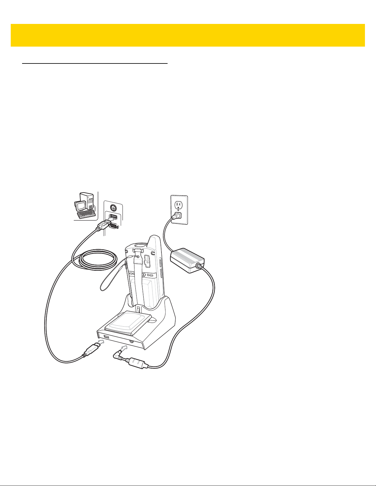
Setup
Figure 2-1 Single Slot USB Cradle Power and USB Connections
Charging the MC67 Battery
Connect the cradle to power. Insert the MC67 into the MC67 slot to begin charging.

Figure 2-2 MC67 Battery Charging
Spare Battery Charging LED
Charging the Spare Battery
Accessories 2 - 5
Figure 2-3 Spare Battery Charging
Battery Charging
The Single Slot USB cradle charges the MC67’s main battery and a spare battery simultaneously.
The MC67’s Charging/Battery Status LED indicates the status of the battery charging in the MC67. See Table 1-1
on page 1-4 for charging status indications.
The spare battery charging LED on the cradle indicates the status of the spare battery charging in the cradle. See
below for charging status indications.
The 3600 mAh battery fully charges in approximately six hours.

2 - 6 MC67 with Android™ OS Integrator Guide
Table 2-2 Spare Battery LED Charging Indicators
Spare Battery LED (on cradle) Indication
Slow Blinking Amber Spare battery is charging.
Solid Amber Spare battery is fully charged.
Fast Blinking Amber Charging error.
Off Not charging.
Charging Temperature
Charge batteries in temperatures from 0 °C to 40 °C (32 °F to 104 °F). Charging is intelligently controlled by the
MC67.
To accomplish this, for small periods of time, the MC67 or cradle alternately enables and disables battery charging
to keep the battery at acceptable temperatures. The MC67 or cradle indicates when charging is disabled due to
abnormal temperatures via its LED.

Four Slot Ethernet Cradle
Green 100 LED (CRD5501-4001ER)
Green 1000 LED (CRD5501-4001ER)
Power Port
Ethernet Ports
Primary Port
Ethernet Switch,
Router, or Hub
Connection
This section describes how to set up and use a Four Slot Ethernet cradle with the MC67.
The Four Slot Ethernet cradle:
•
Provides 5.4 VDC power for operating the MC67.
•
Connects the MC67 (up to four) to an Ethernet network.
•
Simultaneously charges up to four MC67s.
Accessories 2 - 7
Figure 2-4 Four Slot Ethernet Cradle
CRD5501-4001ER Setup
Connect the Four Slot Ethernet cradle to a power source and to an Ethernet switch, router, or hub, or a port on the
host device.
Figure 2-5 CRD5501-4001ER Four Slot Ethernet Cradle Connection

2 - 8 MC67 with Android™ OS Integrator Guide
Secondary Port
Primary Port
To Switch To Power Supply To Power Supply
Right LED
Left LED
Daisy Chaining Ethernet Cradles
Daisy chain up to four Four Slot Ethernet cradles to connect several cradles to an Ethernet network. Use either a
straight or crossover cable. Daisy-chaining should not be attempted when the main Ethernet connection to the first
cradle is 10 Mbps as throughput issues will almost certainly result.
To daisy chain more than Four Slot Ethernet cradles:
1. Connect power to each Four Slot Ethernet cradle.
2. Connect an Ethernet cable to the Primary Port of the first cradle and to the Ethernet switch.
3. On the first Four Slot Ethernet cradle, lift or remove the label flap and connect a second Ethernet cable to the
Secondary Port.
4. Connect the other end of the Ethernet cable to the Primary Port of the second Four Slot Ethernet cradle.
5. Connect additional cradles as described in step 3 and step 4.
Figure 2-6 Daisy chaining Four Slot Ethernet Cradles
LED Indicators (CRD5501-4001ER)
There are two green LEDs on the front of the cradle and two green LED on the Primary port on the back of the
cradle. These green LEDs light and blink to indicate the data transfer rate. When the LEDs are not lit the transfer
rate is 10 Mbps.
Table 2-3 CRD5501-4001ER LED Indicators
Data Rate Left 1000 LED (Green) Right 100 LED (Green)
1 Gbps On/Blink Off
100 Mbps Off On/Blink
10 Mbps Off Off
Ethernet Settings
The following settings can be configured when using Ethernet communication:
•
Proxy Settings
•
Static IP.
Accessories 2 - 9
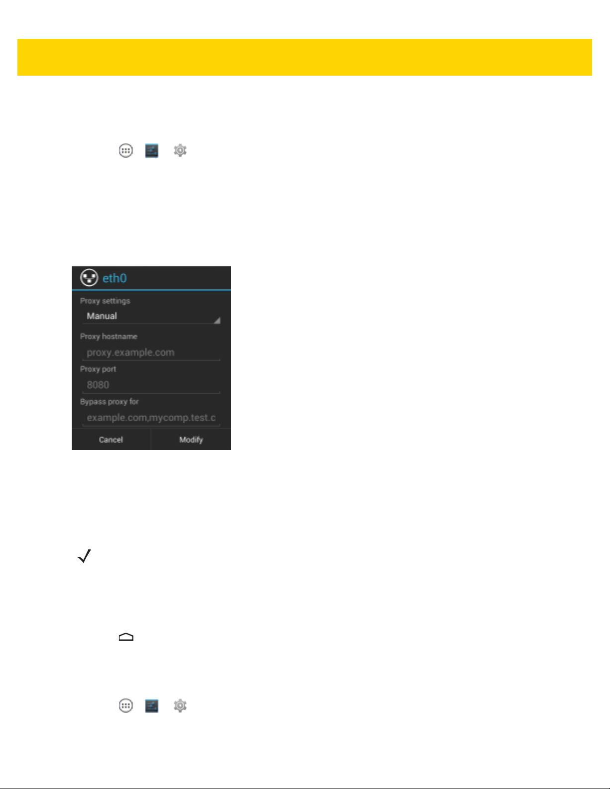
Configuring Ethernet Proxy Settings
The MC67 includes Ethernet cradle drivers. After inserting the MC67, configure the Ethernet connection:
1. Touch > or .
2. Touch Ethernet.
3. Slide the switch to the ON position.
4. Place the MC67 into the Ethernet cradle slot.
5. Touch and hold Eth0 until the menu appears.
6. Touch Modify Proxy.
Figure 2-7 Ethernet Proxy Settings
7. Touch the Proxy settings drop-down list and select Manual.
8. In the Proxy hostname field, enter the proxy server address.
9. In the Proxy port field, enter the proxy server port number.
NOTE When entering proxy addresses in the Bypass proxy for field, do not use spaces or carriage returns
between addresses.
10. In the Bypass proxy for text box, enter addresses for web sites that do not require to go through the proxy
server. Use the separator “|” between addresses.
11. Touch Modify.
12. Touch .
Configuring Ethernet Static IP Address
The MC67 includes Ethernet cradle drivers. After inserting the MC67, configure the Ethernet connection:
1. Touch > or .
2. Touch Ethernet.

2 - 10 MC67 with Android™ OS Integrator Guide
3. Slide the switch to the ON position.
4. Place the MC67 into the Ethernet cradle slot.
5. Touch and hold Eth0 until the menu appears.
6. Touch Disconnect.
Figure 2-8 Ethernet Proxy Settings
7. Touch and hold Eth0 until the menu appears.
8. Touch the IP setting drop-down list and select Static.
9. In the IP address field, enter the proxy server address.
10. If required, in the Gateway text box, enter a gateway address for the device.
11. If required, in the Network prefix length text box, enter a the prefix length.
12. If required, in the DNS 1 text box, enter a Domain Name System (DNS) address.
13. If required, in the DNS 2 text box, enter a DNS address.
14. Touch Connect.
15. Touch .
Charging the MC67
Insert the MC67 into a slot to begin charging. The MC67’s Charging/Battery Status LED shows the status of the
battery charging in the MC67.

Accessories 2 - 11
The 3600 mAh battery fully charges in approximately six hours.
Charging Temperature
Charge batteries in temperatures from 0 °C to 40 °C (32 °F to 104 °F). Charging is intelligently controlled by the
MC67.
To accomplish this, for small periods of time, the MC67 alternately enables and disables battery charging to keep
the battery at acceptable temperatures. The MC67 indicates when charging is disabled due to abnormal
temperatures via its LED.

2 - 12 MC67 with Android™ OS Integrator Guide
Power Port
Four Slot Charge Only Cradle
This section describes how to set up and use a Four Slot Charge Only cradle with the MC67.
The Four Slot Charge Only cradle:
•
Provides 5.4 VDC power for operating the MC67.
•
Simultaneously charges up to four MC67s.
The user cannot ActiveSync using the Four Slot Charge Only cradle. To ActiveSync with a host computer, use the
Single Slot USB cradle.
Setup
Connect the Four Slot Charge Only cradle to a power source.
Figure 2-9 Four Slot Charge Only Cradle Setup
Charging the MC67
Insert the MC67 into a slot to begin charging. The MC67’s Charging/Battery Status LED shows the status of the
battery charging in the MC67.
The 3600 mAh battery fully charges in approximately six hours.
Charging Temperature
Charge batteries in temperatures from 0 °C to 40 °C (32 °F to 104 °F). Charging is intelligently controlled by the
MC67.
To accomplish this, for small periods of time, the MC67 alternately enables and disables battery charging to keep
the battery at acceptable temperatures. The MC67 indicates when charging is disabled due to abnormal
temperatures via its LED.

Wall Mount Bracket
Mounting Screw (4)
Mounting Tab (2)
Mounting Slot
Mounting Screw (2)
Four Slot
Cradle Bottom
Use the optional Wall Mount Bracket to mount a four slot cradle to a wall. To attach the Wall Mount Bracket:
1. Use the Wall Mount Bracket as a template and mark the locations of the four mounting screws.
NOTE Use fasteners appropriate for the type of wall and the Wall Mount Bracket mounting slots. The Wall Mount
Bracket mounting slots are designed for a fastener with a #8 pan head. Fasteners must be able to hold a
minimum of 4.9 Kg (10.8 lbs).
2. Mount the fasteners to the wall. The screw heads should protrude about a half of an inch from the wall.
3. Slip the Wall Mount Bracket over the screw heads and slide the bracket down over the screw heads.
4. Tighten the screws to secure the bracket to the wall.
Accessories 2 - 13
Figure 2-10 Wall Mount Bracket
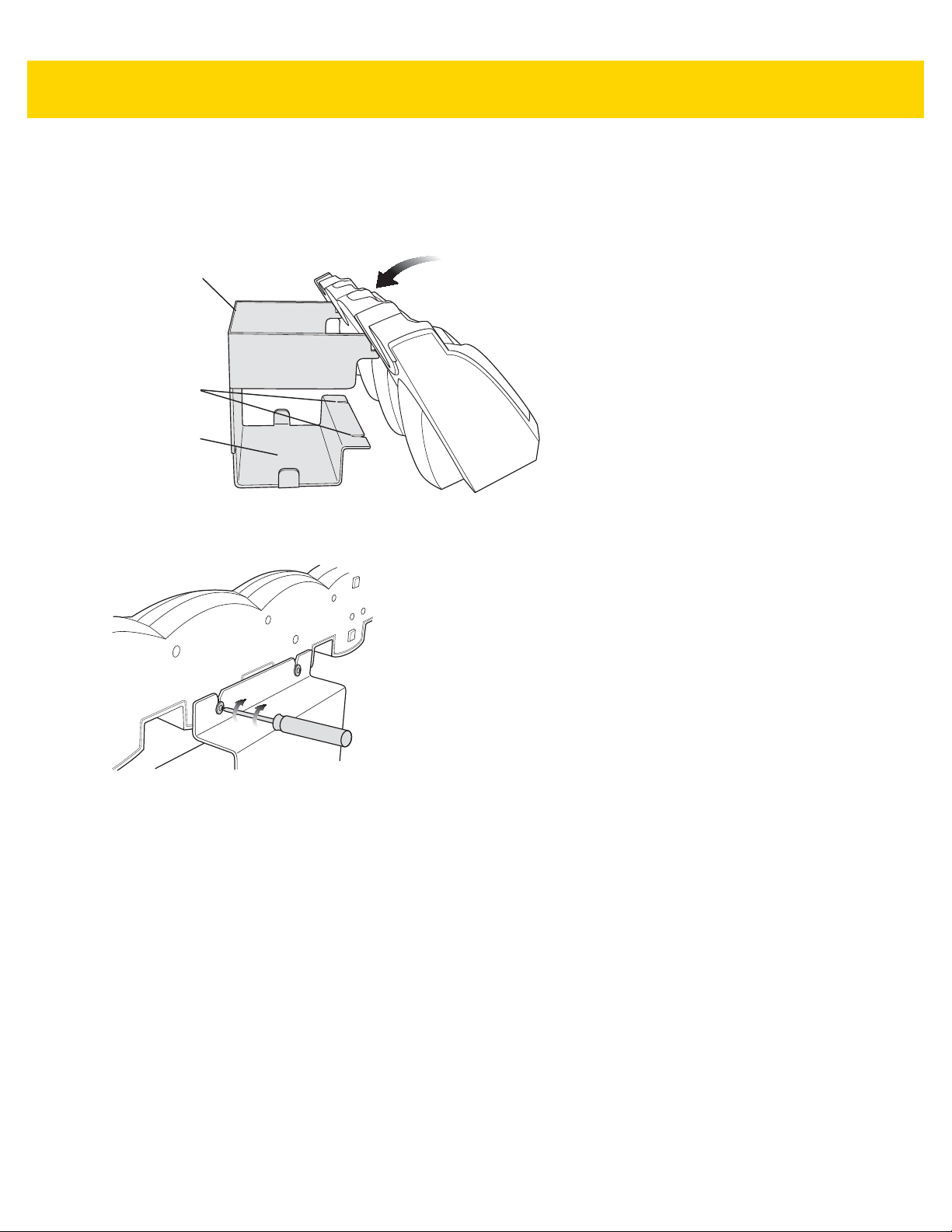
Mounting a Four Slot Cradle
To mount a four slot cradle:
1. Screw the supplied screws into the bottom of the four slot cradle. The screw heads should protrude about a
quarter of an inch from the cradle.
Figure 2-11 Cradle Mounting Screws
2 - 14 MC67 with Android™ OS Integrator Guide
Wall Mount
Bracket
Screw Slots
Power Supply
Well
2. Align the Wall Mount Bracket mounting tabs with the mounting slots in the back of the four slot cradle. Slip the
two mounting tabs into mounting slots.
3. Swing the four slot cradle down onto the mounting bracket and align the mounting screws so that they fit into
the screw slots.
Figure 2-12 Wall Mount Bracket
4. Tighten the mounting screws to secure the four slot cradle to the bracket.
Figure 2-13 Mounting Screws
5. Connect power. The power supply should be located in the power supply well.
VCD5500 Vehicle Cradle
This section describes how to set up and use a VCD5500 vehicle cradle with the MC67.
Once installed in a vehicle, the cradle:
•
holds the MC67 securely in place
•
provides power for operating the MC67
•
re-charges the battery in the MC67
Requirements
For mounting:
•
four #8-32 self-locking nuts
•
four #8 washers
•
a drill with a #6 drill bit (.204”)
Accessories 2 - 15
For power connection:
•
power input cable (optional), p/n 25-61987-01R or 25-128974-01R
•
UL Listed in-line fuse rated 250V, 5A (included), must be used if not connecting to vehicle’s fuse panel
•
in-line fuse holder (included), must be used if not connecting to vehicle’s fuse panel
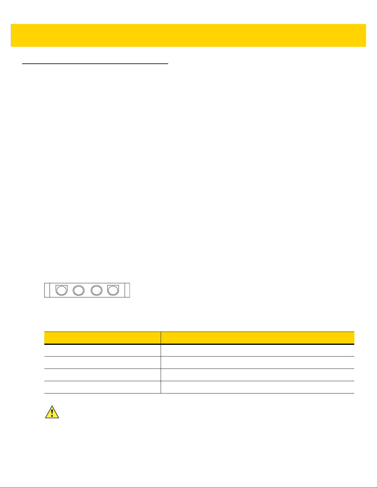
Connector Pin-Outs
1
Figure 2-14 VCD5500 Power Connection
Table 2-4 Power Input Cable
Pin Signal
1 Chassis ground (Black Wire)
2 Chassis ground (Bare Wire)
3V+ (Red Wire)
4V+ (Red Wire)
CAUTION ROAD SAFETY - Do not use the MC67 while driving. Park the vehicle first. Always ensure the MC67 is
fully inserted into the cradle. Do not place it on the seat or where it can break loose in a collision or
sudden stop. Lack of proper insertion may result in property damage or personal injury. Zebra is not
responsible for any loss resulting from the use of the products while driving. Remember: Safety comes
first.

2 - 16 MC67 with Android™ OS Integrator Guide
1.5”
1.2”
Mounting the Cradle
CAUTION Only mount the Vehicle Cradle in a vertical position with the release level at the top or in a horizontal
position with the MC67 display facing up. Never mount the vehicle cradle on the side or upside down
or on a wall that can be subject to impact or collision of greater than 40Gs, in accordance with SAE
J1455 Section 4.10.3.5.
1. Select a mounting location for the cradle. It should be flat, and must provide adequate support for the cradle.
NOTE If using the GPS functionality of the MC67, ensure that the vehicle cradle is positioned so that the MC67
has a clear unobstructed view of the sky.
2. Prepare the mounting surface to accept four #8-32 studs, using the mounting template below. Drill four holes
with a #6 drill bit.
Figure 2-15 Vehicle Cradle Mounting Template
3. Position the cradle on the mounting surface.
4. Fasten it using four #8 washers and four #8-32 self-locking nuts.
CAUTION Do not install a VCD5500 Vehicle Cradle on or near an air bag cover plate or within an aerobic zone.
Also, do not install it in a location that affects vehicle safety or driveability.
Power Connection
Please read all of the following instructions before beginning.
WARNING! A properly trained technician must perform the power connection. Improper connection can
damage your vehicle, cradle or MC67. Refer to the vehicle’s Owner’s Manual for instructions
To connect the cradle to power:
CAUTION When setting up connection for this cradle, only use the power input cable, part number 25-61987-01R
1. Locate the vehicle power source.
for removing power.
or 25-128974-01R.

Accessories 2 - 17
NOTE The ideal location for connecting the vehicle cradle power input cable would be an accessory output in
your vehicle’s fuse panel. The vehicle cradle should be added to a circuit with a maximum load capacity
for the cradle and the original circuit. Refer to the vehicle’s Owner’s Manual for identification of the circuit.
If a fused output is not available, the vehicle cradle must be installed with the provided in-line fuse holder
and UL Listed 5A fuse. The fuse protects the vehicle from an electrical short on the power line to the
cradle.
To use the cradle to charge the MC67 and spare battery, when the vehicle’s ignition is off, connect the
cradle to unswitched power.
2. Route the power input cable from the cradle’s power port to the connection point for the vehicle’s power
source.
CAUTION The means of routing and securing the power input cable from the cradle through to the vehicle power
source is extremely important. Hazards associated with improper wiring can be severe. To avoid
unintentional contact between the wire and any sharp edges, provide the cable with proper bushings
and clamping where it passes through openings. If the wire is subjected to sharp surfaces and excess
engine vibration, the wiring harness insulation can wear away, causing a short between the bare wire
and chassis. This can start a fire.
To avoid any mishaps, all wiring should be routed away from moving parts, high temperature
areas and any contaminants.
3. When using the supplied in-line fuse holder (which must be used if not connecting to vehicle’s fuse panel):
a. Ensure the fuse holder contains a 5A UL Listed slow-blow fuse.
b. Splice the fuse holder to the end of the red V+ wire, as shown above. Make the distance from the fuse to
the power connection point as short as possible.
Figure 2-16 Vehicle Cradle Power Connection
4. Prepare the cable termination.
a. Red wire: connect to a +12/24 V vehicle power source.
b. Black wire and Shield wire: connect to vehicle ground wire or chassis ground.
NOTE How the cable terminates depends on the vehicle. If the vehicle has a power output connector, then you
must attach a mating connector to the end of the power cable. You may be able to connect to a fuse panel
with a simple blade terminal or commercially available connector. Consult the vehicle Owner’s Manual for
information on how to access the power supply in the vehicle.
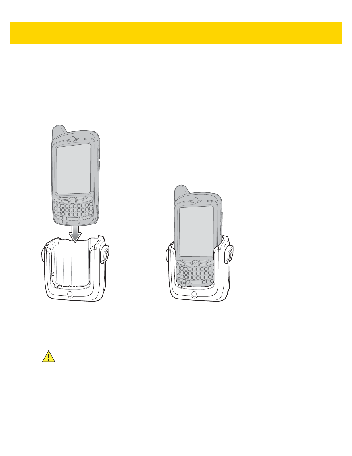
2 - 18 MC67 with Android™ OS Integrator Guide
5. Connect the power input cable into the power port on the cradle.
To see if the cradle has power, insert the MC67. The Charging LED on the MC67 blinks slowly to indicate charging
and turns solid amber when the battery is completely charged. See LED Ch ar gin g Indi cator s on pa ge 1- 4 for other
indications.
Charging the MC67 Battery
1. Insert the MC67 into the vehicle cradle to begin charging.
Figure 2-17 MC67 Battery Charging
2. Press the MC67 down to ensure it is seated properly.
A click indicates that the MC67 button release locking mechanism is enabled and the MC67 is locked in
place.
CAUTION Ensure the MC67 is fully inserted in the cradle. Lack of proper insertion may result in property damage
or personal injury. We are not responsible for any loss resulting from the use of the products while
driving.
Removing the MC67
1. Press the release levers on the cradle.
2. Pull the MC67 up and out of the cradle.
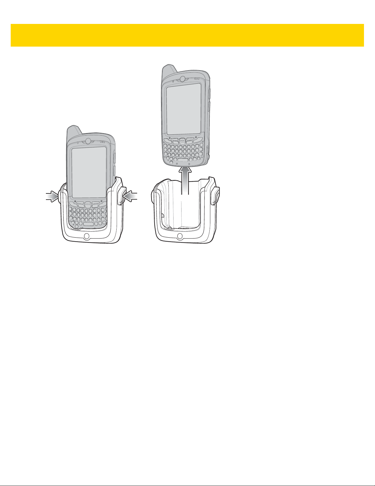
Accessories 2 - 19
Figure 2-18 Removing the MC67
Charging the MC67
Insert the MC67 into a slot to begin charging. The MC67’s Charging/Battery Status LED shows the status of the
battery charging in the MC67.
The 3600 mAh battery fully charges in approximately six hours.
Charging Temperature
Charge batteries in temperatures from 0 °C to 40 °C (32 °F to 104 °F). Charging is intelligently controlled by the
MC67.
To accomplish this, for small periods of time, the MC67 alternately enables and disables battery charging to keep
the battery at acceptable temperatures. The MC67 indicates when charging is disabled due to abnormal
temperatures via its LED.

2 - 20 MC67 with Android™ OS Integrator Guide
Battery Charging
LEDs (4)
Battery
Four Slot Battery Charger
This section describes how to use the Four Slot Battery Charger to charge up to four MC67 spare batteries.
Spare Battery Charging
1. Connect the charger to a power source.
2. Insert the spare battery into a spare battery charging well and gently press down on the battery to ensure
proper contact.
Figure 2-19 Four Slot Battery Charger Setup
Battery Charging Indicators
An amber LED is provided for each battery charging well. See Table 2-2 on page 2-6 for charging status
indications. The 3600 mAh battery charges in approximately six hours.
Charging Temperature
Charge batteries in temperatures from 0 °C to 40 °C (32 °F to 104 °F). Charging is intelligently controlled by the
charger in order to ensure safe operation and optimize long-term battery life.
To accomplish this, for small periods of time, the charger alternately enables and disables battery charging to keep
the battery at acceptable temperatures. The charger indicates when charging is disabled due to abnormal
temperatures via its LED. See Table 2-2 on page 2-6.

Table 2-5 Spare Battery LED Charging Indicators
Off No spare battery in slot; spare battery not placed correctly; cradle is not
Fast Blinking Amber Error in charging; check placement of spare battery.
Slow Blinking Amber Spare battery is charging.
Solid Amber Charging complete.
Cables
This section describes how to set up and use the cables. The cables are available with a variety of connection
capabilities.
The following communication/charge cables are available:
Accessories 2 - 21
LED Indication
powered.
•
USB Charging cable
•
Charge Only cable
•
Auto Charge cable
•
DEX cable.
USB Charging Cable
The USB Charging cable provides the MC67 with operating and charging power when used with the Zebra
approved power supply and AC line cord and synchronize information between the MC67 and a host computer.
Figure 2-20 USB Charging Cable Setup

2 - 22 MC67 with Android™ OS Integrator Guide
Charge Only Cable
The Charge Only cable provide the MC67 with operating and charging power when used with the Zebra approved
power supply.
Figure 2-21 Charge Only Cable Setup
Auto Charge Cable
The Auto Charge cable plugs into a vehicle cigarette lighter and provide the MC67 with operating and charging
power.
Figure 2-22 Auto Charge Cable
Connecting Cables to the MC67
1. If required, connect the cable power input connector to the Zebra approved power source.
2. Slide the bottom of the MC67 into the connector cup end of the cable until the MC67 is firmly seated in the cup.
3. Slide the two locking tabs up until they both lock into position.

Accessories 2 - 23
Locking Tab
Figure 2-23 Cable Cup Locking Tabs
4. To remove, slide the two locking tab down and remove the cable from the MC67.
Charging the MC67
Insert the MC67 into a slot to begin charging. The MC67’s Charging/Battery Status LED shows the status of the
battery charging in the MC67.
The 3600 mAh battery fully charges in approximately six hours.
Charging Temperature
Charge batteries in temperatures from 0 °C to 40 °C (32 °F to 104 °F). Charging is intelligently controlled by the
MC67.

2 - 24 MC67 with Android™ OS Integrator Guide
To accomplish this, for small periods of time, the MC67 alternately enables and disables battery charging to keep
the battery at acceptable temperatures. The MC67 indicates when charging is disabled due to abnormal
temperatures via its LED.
Vehicle Holder
WARNING! Some countries prohibit the mounting of any electronic device in any location on the vehicle
dashboard and windshield. Be sure to check your local laws acceptable mounting areas
before installing the auto mounting kit.
Installation Reminders
Figure 2-24 Vehicle Holder Mounting
•
Do not mount the vehicle holder where it will obscure the driver’s view of the road.
•
Do not mount the vehicle holder near the driver seat air bag deployment area.
•
Do not place the MC67 on top of the dashboard or anywhere without securing it in the vehicle holder.
•
Do not mount the vehicle holder near the passenger seat air bag deployment area.
•
Install the vehicle holder on the surface of your vehicle that is reasonably flat and free of dirt and oil.
Device Mounting Precautions
•
Some countries prohibit the mounting of any electronic device in any location on the vehicle dashboard. Be
sure to check your local laws acceptable mounting areas before installing the vehicle holder.
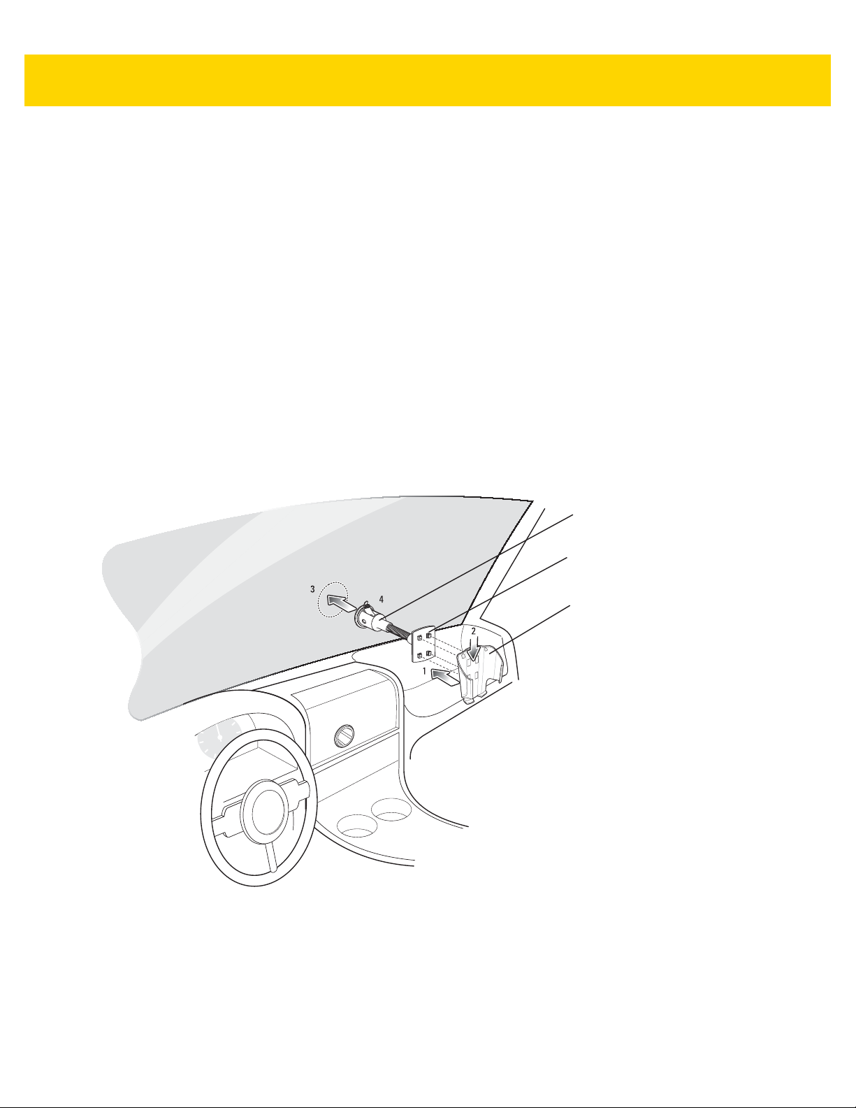
Accessories 2 - 25
Cradle Plate
Cradle
Suction Cup Mount
•
The heating and cooling cycle of a vehicle’s interior will in some cases loosen the adhesion of the suction
cup. Check the vacuum seal of the vehicle mount kit for adequate adhesion each time you use the unit, and
reinstall if necessary.
•
If the vehicle holder has problems staying on, clean the plastic suction cup with alcohol, then reinstall.
Installation
Install the vehicle mount on the surface of your vehicle that is reasonably flat and free of dirt and oil. Clean the
mounting surface with a glass cleaner and a clean cotton cloth. Install the vehicle mount on the windshield or other
flat car surface using the supplied mounting disc.
Assembly
1. Insert the vehicle holder’s cradle plate to the holes on the back of the cradle.
2. Push the cradle down until both parts are engaged.
Windshield Installation
1. Fix the suction cup mount to the selected area with the suction lever facing up.
Figure 2-25 Windshield Installation
2. Flip the lever down to create a vacuum between the suction cup and the mounting surface.
3. Make sure that the suction bond is strong enough before proceeding to the next step.
4. Slide the MC67 into the cradle.

2 - 26 MC67 with Android™ OS Integrator Guide
Locking Tab
Figure 2-26 Insert MC67 into Vehicle Holder
5. Connect the auto charger cable to the MC67 and slide the two locking tabs up to secure the cable cup to the
MC67.
6. Connect the other end to the cigarette lighter socket.
NOTE Prior to removing the MC67 from the vehicle holder, disconnect the auto-charge cable from the MC67.
The LED indicator on the right side of the touch screen lights up orange during charging.
Flat Surface Installation
1. Remove the plastic sheet on the bottom of the mounting disc.
2. Place the disc, sticky side down, on a clean flat surface.
Figure 2-27 Mounting Disk
3. Fix the suction cup mount to the disc with the suction lever facing up.
4. Flip the lever down to create a vacuum between the suction cup and the disc.
5. Make sure that the suction bond is strong enough before proceeding to the next step.

6. Slide the MC67 into the cradle.
Accessories 2 - 27
Figure 2-28 Vehicle Holder Mounted on Flat Surface
7. Connect the auto charger cable to the MC67 and slide the two locking tabs up to secure the cable cup to the
MC67.
8. Connect the other end to the cigarette lighter socket.
The LED indicator on the right side of the touch screen lights up orange during charging.
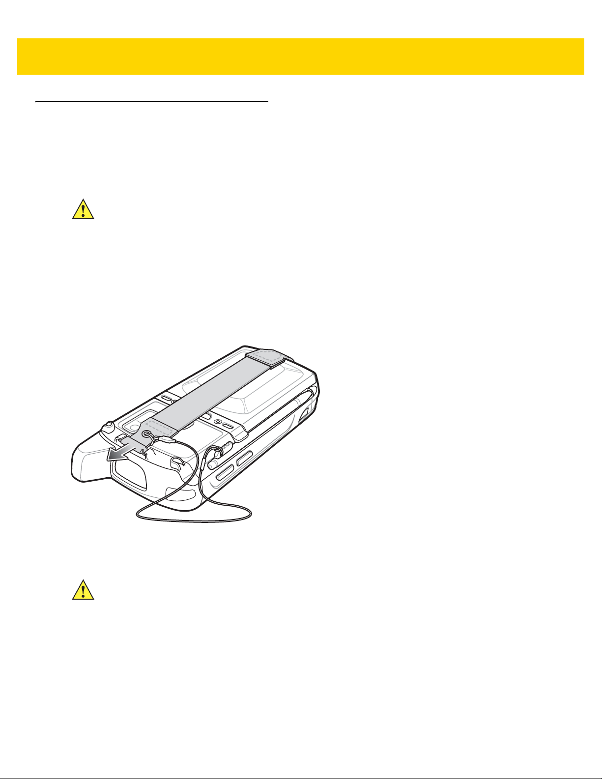
2 - 28 MC67 with Android™ OS Integrator Guide
Hand Strap Replacement
Removal
To remove a hand strap from the MC67:
CAUTION Close all running applications prior to replacing the hand strap. The backup battery maintains data for
up to 15 minutes. If replacement takes longer than 15 minutes data may be lost.
1. If the MC67 is in suspend mode, press the red Power button to wake the MC67.
2. Press the red Power button.
The Power Action Key window appears.
3. Ta p Safe Battery Swap.
The Data Capture LED lights red.
4. When the LED turns off, remove the hand strap.
Figure 2-29 Hand Strap Clip Removal
5. Remove the battery.
CAUTION When removing hand strap pin, be careful not to damage hand strap mounting area.
6. Using a small flat screwdriver, push the head of the screwdriver between the hand strap pin and the bottom of
the housing as shown below.
7. Pry the hand strap and pin up and out of the hand strap mount area.

Accessories 2 - 29
21
43
Figure 2-30 Hand Strap and Pin Removal
8. Repeat for the other side of the hand strap.
9. Remove pin from the hand strap.
Figure 2-31 Pin Removal
10. Pull hand strap through hand strap slot.
Installation
To install a new hand strap:
1. Feed bottom end of hand strap into hand strap slot on the bottom of the MC67.
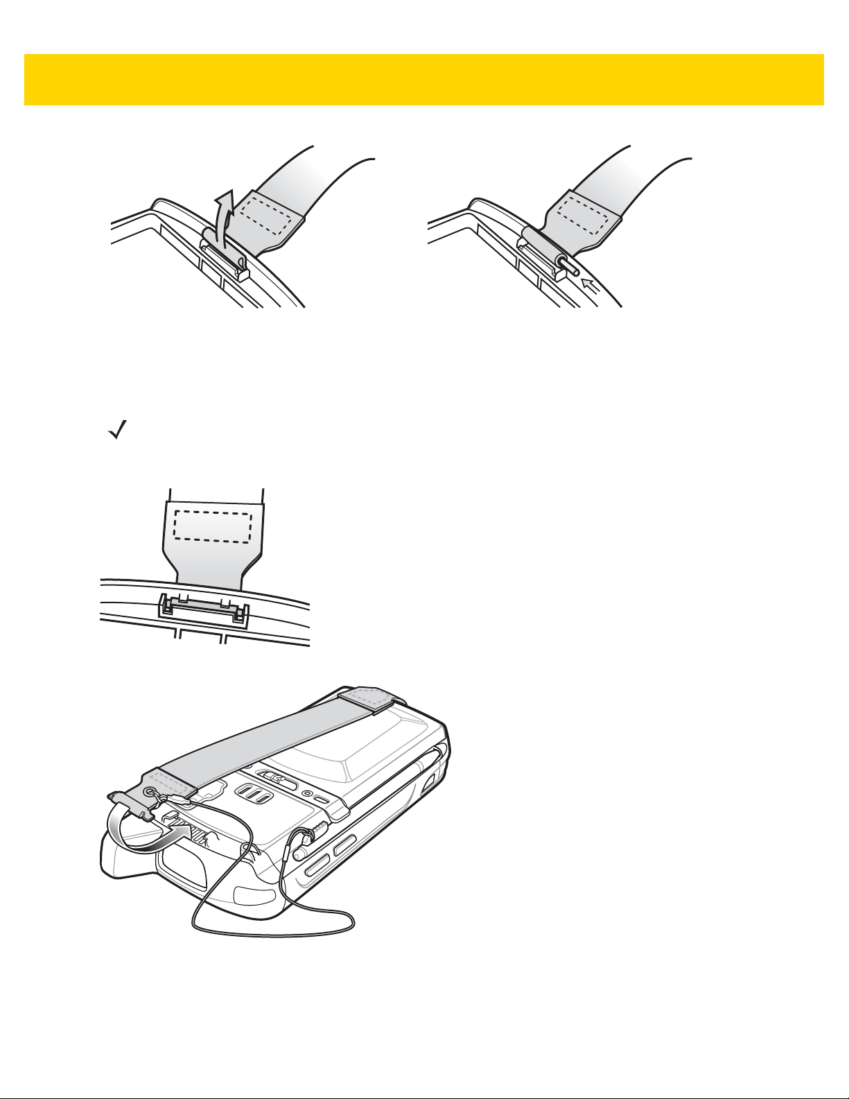
2 - 30 MC67 with Android™ OS Integrator Guide
Figure 2-32 Feed Hand Strap into Hand Strap Slot
2. Slide pin into bottom of hand strap.
3. Center the pin in the hand strap loop.
NOTE Hand strap and pin should fit securely into the hand strap mounting area. When pulling on hand strap use
enough force to engage pin into place.
4. Pull hand strap so that the pin and bottom of hand strap slide into position in the mounting area.
Figure 2-33 Pin and Hand Strap in Mounting Area
Figure 2-34 Slide Hand Strap and Tether Over Hand Strap Mount
5. Slide tether loop over hand strap.
6. Insert the hand strap clip into the slot on the device. Ensure that it is securely in place.

CHAPTER 3 USB COMMUNICATION
This chapter provides information for transferring files between the device and a host computer.
Connecting to a Host Computer via USB
Connect the MC67 to a host computer using the USB Charging cable or Single Slot USB cradle to transfer files
between the MC67 and the host computer.
CAUTION When connecting the MC67 to a host computer, follow the host computer’s instructions for connecting
and disconnecting USB devices, to avoid damaging or corrupting files.
NOTE A microSD card must be installed in the MC67 to transfer files between the MC67 and host computer.
Connecting to the MC67 as a Media Device
1. Connect the USB Charging cable to the MC67 and then to the host computer or place the MC67 into a Single
Slot USB cradle that is connected to a host computer.
Connected as a media device or Connected as an installer appears on the Status bar.
2. If Connected as an installer appears, pull down the Notification shade and touch Connected as an installer
and then touch Media device (MTP).
3. On the host computer, open a file explorer application.
4. Locate the MC67NA as a portable device.
5. Open the SD card folder.
6. Copy or delete files as required.
Connecting to the MC67 as an Installer
1. Connect the USB Charging cable to the MC67 and then to the host computer or place the MC67 into a Single
Slot USB cradle that is connected to a host computer.

3 - 2 MC67 with Android™ OS Integrator Guide
Connected as a media device or Connected as an installer appears on the Status bar.
2. If Connected as media device appears, pull down the Notification shade and touch Connected as media
device and then touch Media device (MTP) to de-select.
3. Touch Turn on USB Storage.
4. On the host computer, open a file explorer application.
The MC67 storage appears as Removable Disk.
5. Locate the MC67 as a devices within Removable Storage.
6. Open the Removable Disk.
7. Copy or delete files as required.
8. On the MC67, touch Turn off USB storage
Disconnect from the Host Computer
CAUTION Carefully follow the host computer’s instructions to unmount the microSD card and disconnect USB
devices correctly to avoid losing information.
1. On the host computer, unmount the device.
2. Remove the USB Charging cable from the MC67 or remove the MC67 from the Single Slot USB cradle.
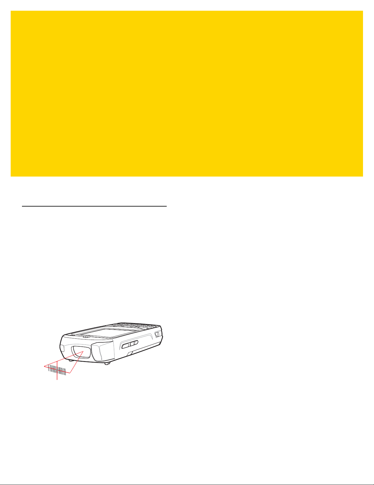
CHAPTER 4 DATAWEDGE
CONFIGURATION
DataWedge is an application that reads data, processes the data and sends the data to an application.
Basic Scanning
Scanning can be performed using either the imager or the rear-facing camera.
Using the Imager
To capture bar code data:
1. Ensure that an application is open on the MC67 and a text field is in focus (text cursor in text field).
2. Aim the exit window at a bar code.
3. Press and hold the a Scan button. The red laser aiming pattern turns on to assist in aiming. Ensure that the bar
code is within the area formed by the aiming pattern. The Data Capture LED lights red to indicate that data
capture is in process.
Figure 4-1 Data Capture
4. The Data Capture LED lights green, a beep sounds and the MC67 vibrates, by default, to indicate the bar code
was decoded successfully. The captured data appears in the text field.
Using the Camera
To capture bar code data:
1. Ensure that an application is open on the MC67 and a text field is in focus (text cursor in text field).

4 - 2 MC67 with Android™ OS Integrator Guide
2. Aim the rear-facing camera at a bar code.
3. Press and hold a Scan button. By default, a preview window appears on the screen. The Data Capture LEDs
light red to indicate that data capture is in process.
Figure 4-2 Data Capture with Camera
4. Move the MC67 until the bar code is centered under the red target.
5. The Left and Right LEDs light green, a beep sounds and the MC67 vibrates, by default, to indicate the bar code
was decoded successfully. The captured data appears in the text field.
Profiles
DataWedge is based on profiles and plug-ins. A profile contains information on how DataWedge should behave
with different applications.
Profile information consists of:
•
•
•
•
Using profiles, each application can have a specific DataWedge configuration. For example, each user application
can have a profile which outputs scanned data in the required format when that application comes to the
foreground. DataWedge can be configured to process the same set of captured data differently based on the
requirements of each application.
DataWedge includes the following visible and hidden pre-configured profiles which support specific built-in
applications:
•
Associated application
Input plug-in configurations
Output plug-in configurations
Process plug-in configurations.
Visible profiles:
•Profile0 - created automatically the first time DataWedge runs. Generic profile used when there are no
user created profiles associated with an application.
• Launcher - disables scanning when the Launcher is in foreground.
•DWDemo - provides support for the DWDemo application.

DataWedge Configuration 4 - 3
•
Hidden profiles (not shown to the device):
• RD Client - provides support for MSP.
•MSP Agent - provides support for MSP.
• MspUserAttribute - provides support for MSP.
•Camera - disables scanning when the default camera application is in foreground.
• RhoElements - disables scanning when RhoElements is in foreground.
Profile0
Profile0 can be edited but cannot be associated with an application. That is, DataWedge allows manipulation of
plug-in settings for Profile0 but it does not allow assignment of a foreground application. This configuration allows
DataWedge to send output data to any foreground application other than applications associated with user-defined
profiles when Profile0 is enabled.
Profile0 can be disabled to allow DataWedge to only send output data to those applications which are associated
in user-defined profiles. For example, create a profile associating a specific application, disable Profile0 and then
scan. DataWedge only sends data to the application specified in the user-created profile. This adds additional
security to DataWedge enabling the sending of data only to specified applications.
Plug-ins
A plug-in is a software module utilized in DataWedge to extend its functionality to encompass technologies such as
bar code scanning. The plug-ins can be categorized into three types based on their operations:
•
•
•
Input Plug-ins
An Input Plug-in supports an input device, such as a bar code scanner contained in, or attached to the device.
DataWedge contains base plug-ins for these input devices.
•
•
Input Plug-ins
Output Plug-ins
Process Plug-ins.
Bar Code Scanner Input Plug-in – The Bar Code Scanner Input Plug-in is responsible for reading data from
the integrated bar code scanner and supports different types of bar code readers including laser, imager and
internal camera. Raw data read from the bar code scanner can be processed or formatted using Process
Plug-ins as required. DataWedge has built-in feedback functionality for the bar code scanner to issue user
alerts. The feedback settings can be configured according to user requirement.
MSR Input Plug-in – The Magnetic Stripe Reader (MSR) Input Plug-in is responsible for reading data from
an MSR. Raw data read from the MSR can be processed or formatted using Process Plug-ins as required.
DataWedge has built-in feedback functionality for the MSR to issue user alerts. The feedback settings can
be configured according to user requirement.
Process Plug-ins
Process Plug-ins are used in DataWedge to manipulate the received data according to the requirement, before
sending to the foreground application via the Output Plug-in.

4 - 4 MC67 with Android™ OS Integrator Guide
•
Basic Data Formatting Process Plug-in– The Basic Data Formatting Plug-in allows DataWedge to add a
prefix and/or a suffix to the captured data before passing it to an Output Plug-in.
•
Advanced Data Formatting Process Plug-in– The Advanced Data Formatting Plug-in allows DataWedge
to apply rules (actions to be performed based on defined criteria) to the data received via an input plug-in
before passing it to an Output Plug-in.
Output Plug-ins
Output Plug-ins are responsible for sending the data from Input Plug-ins to a foreground application on the device.
•
Keystroke Output Plug-in – The Keystroke Output Plug-in collects and sends data received from the Input
Plug-in to the foreground applications by emulating keystrokes.
•
Intent Output Plug-in – The Intent Output Plug-in collects and sends data received from the Input Plug-ins
to foreground applications using the Android Intent mechanism.
•
IP Output Plug-in – The IP Output Plug-in collects and sends data received from the Input Plug-ins to a host
computer via a network connection. Captured data can be sent over an IP network to a specified IP address
and port using either TCP or UDP transport protocols.
Profiles Screen
To launch DataWedge, touch > DataWedge. By default, three profiles appear:
•
Profile0
•
Launcher
•
DWDemo.
Profile0 is the default profile and is used when no other profile can be applied.
Figure 4-3 DataWedge Profiles Screen
Profile names are color coded. Enabled profiles are white and disabled profiles are gray.
To configure a profile touch the profile name.

DataWedge Configuration 4 - 5
Profile Context Menu
Touch and hold a profile to open a context menu that allows additional actions to be performed on the selected
profile.
Figure 4-4 Profile Context Menu
The profile context menu allows the profile to be edited (same as just tapping on a profile), renamed or deleted.
Options Menu
The menu provides options to create a new profiles, access to general DataWedge settings and DataWedge
version information.
Touch to open the options menu.
Figure 4-5 DataWedge Options Menu
Disabling DataWedge
1. Touch > .
2. Touch .
3. Touch Settings.
4. Touch DataWedge enabled.
The blue check disappears from the checkbox indicating that DataWedge is disabled.

4 - 6 MC67 with Android™ OS Integrator Guide
Creating a New Profile
5. Touch > .
6. Touch .
7. Touch New profile.
8. In the New profile dialog box, enter a name for the new profile. It is recommended that profile names be
unique and made up of only alpha-numeric characters (A-Z, a-z, 0-9).
Figure 4-6 New Profile Name Dialog Box
9. Touch OK.
The new profile name appears in the DataWedge profile screen.
Profile Configuration
To configure the Profile0 or a user-created profile, touch the profile name.
Figure 4-7 Profile Configuration Screen
The configuration screen lists the following sections:
•
Profile enabled
•
Applications
•
Barcode Input
•
MSR Input

DataWedge Configuration 4 - 7
DCP Button
•
Keystroke output
•
Intent Output
•
IP Output.
Data Capture Plus
NOTE Data Capture Plus is only available on MC67 with KitKat operating system.
The Data Capture Plus (DCP) is a DataWedge feature that enables the user to initiate data capture by touching an
area on the screen. A button or screen overlay acts like a scan button.
Figure 4-8 Data Capture Plus Button
The DataWedge profile configuration screen allows the user to configure how the DCP appears on the screen once
the particular profile is enabled. The DCP is hidden by default. Enabling DCP option displays additional
configuration parameters.
Figure 4-9 Data Capture Plus Settings
•
Enable - Select to enable Data Capture Plus (default - disabled).
•
Dock button on - Select position of the button.
• Left or right - Allows user to place the button on either the right or left edge of the screen.
• Left only - Places the button on left edge of the screen.
• Right only - Places the button on the right edge of the screen.
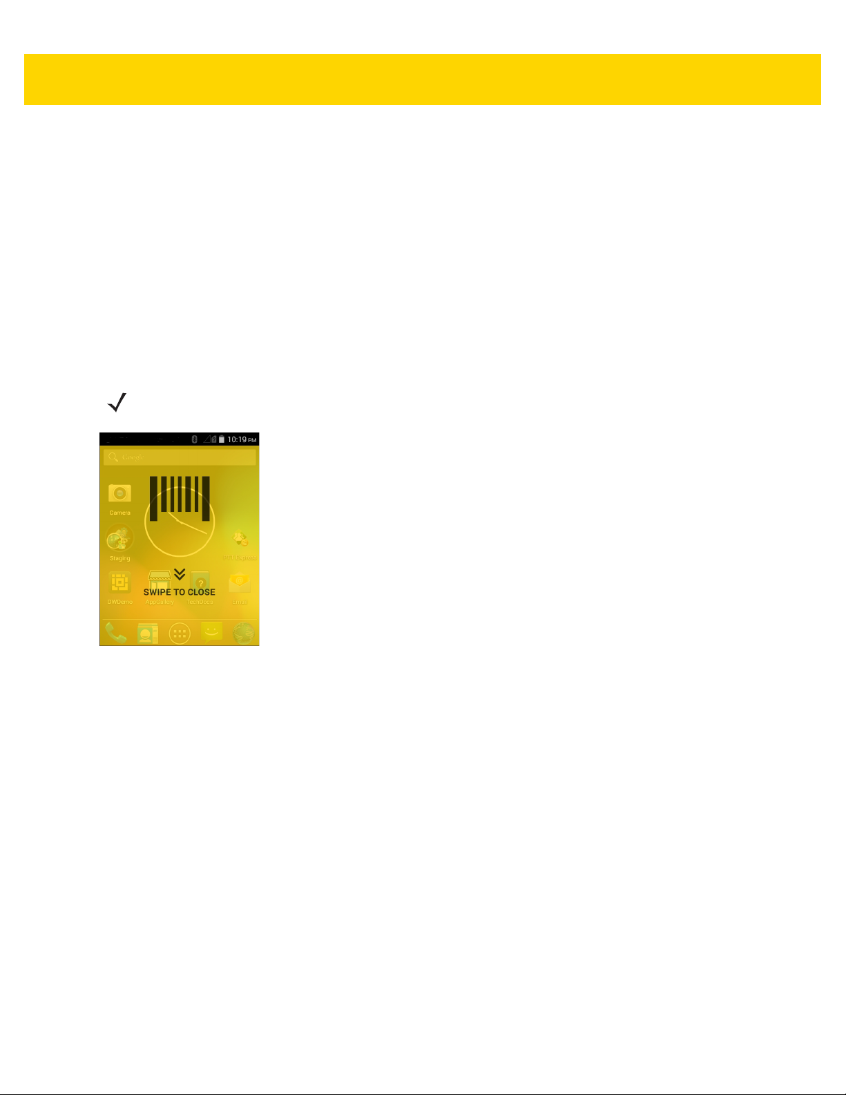
4 - 8 MC67 with Android™ OS Integrator Guide
•
Start in - Select the initial DCP state.
• Fullscreen mode - DCP covers the whole screen.
• Button mode - DCP displays as a circular button on the screen and can be switched to fullscreen mode.
• Button only mode - DCP displays as a circular button on the screen and cannot be switched to fullscreen
mode.
•
Button highest position - Select the top of the range the user is allowed to move the DCP, given as a
percent of the screen height (default - 0).
•
Button lowest position - Select the bottom of the range the user is allowed to move the DCP, given as a
percent of the screen height (default - 100).
•
Drag detect time - Select the time in milliseconds that the scanner waits before activating scanner. This
allows the user to drag the button without initiating scanner (default - 100 ms, maximum 1000 ms).
NOTE The DCP does not appear if the scanner is disabled in the profile even though the Enabled option is set.
Figure 4-10 Fullscreen Mode
Swipe down to return to button mode.
Bar Code Input
Use the Bar Code Input options to configure the Bar Code Scanner Input Plug-in for the profile.
Enabled
Enables or disables this plug-in. A check in the checkbox indicates that the plug-in is enabled.
Scanner Selection
Configures which scanning device to use for bar code data capture when the profile is active.
•
Auto - The software automatically determines the best scanning device.
•
2D Imager - Scanning is performed using the internal 2D Imager.
•
Camera - Scanning is performed using the internal camera.
•
Bluetooth Scanner - Scanning is performed using the optional RS507 imager.

DataWedge Configuration 4 - 9
Decoders
Configures which bar code decoders are enabled or disabled. For best performance disable all unnecessary
decoders.
Touch Decoders. The Barcode input screen appears. A check in the checkbox indicates that the decoder is
enabled. By default the most commonly used decoders are enabled (shown below with an asterisk). The supported
decoders are:
UPC-A* UPC-E0* EAN-13*
EAN-8* Code 128* Code 39*
Interleaved 2 of 5 GS1 DataBar* GS1 DataBar Limited
GS1 DataBar Expanded Datamatrix* QR Code*
PDF417* Composite AB Composite C
MicroQR Aztec* Maxicode*
MicroPDF USPostnet USPlanet
UK Postal Japanese Postal Australian Postal
Canadian Postal Dutch Postal US4state FICS
Codabar* MSI Code 93
Trioptic 39 Discrete 2 of 5 Chinese 2 of 5
Korean 3 of 5 Code 11 TLC 39
Matrix 2 of 5 UPC-E1
Press to return to the previous screen.
Decoder Params
NOTE Not all of the options listed below are supported by the selected scanning option. See the DataWedge
Settings
Use Decode Params to configure individual decoder parameters.
screen for specific supported options.
UPCA
•
Report Check Digit - The check digit is the last character of the symbol used to verify the integrity of the
data. Enables or disables this option. A check in the checkbox indicates that the option is enabled (default enabled).
•
Preamble - Preamble characters are part of the UPC symbol consisting of Country Code and System
Character. Select the appropriate option to match the host system.
There are three options for transmitting a UPCA preamble:
• Preamble None - Transmit no preamble.
• Preamble Sys Char - Transmit System Character only (default).
• Preamble Country and Sys Char - Transmit System Character and Country Code (“0” for USA). Select
the appropriate option to match the host system.

4 - 10 MC67 with Android™ OS Integrator Guide
UPCE0
•
Report Check Digit - The check digit is the last character of the symbol used to verify the integrity of the
data. Enables or disables this option. A check in the checkbox indicates that the option is enabled (default disabled).
•
Preamble - Preamble characters are part of the UPC symbol consisting of Country Code and System
Character. Select the appropriate option to match the host system.
There are three options for transmitting a UPCE0 preamble:
• Preamble Sys Char - Transmit System Character only.
• Preamble Country and Sys Char - Transmit System Character and Country Code (“0” for USA).
• Preamble None - Transmit no preamble (default).
•
Convert UPCE0 To UPCA - Enable to convert UPCE0 (zero suppressed) decoded data to UPC-A format
before transmission. After conversion, the data follows UPC-A format and is affected by UPC-A programming
selections. Disable to transmit UPCE0 decoded data as UPCE0 data, without conversion (default - disabled).
Code128
•
Length1 - Use to set decode lengths (default - 0). See Decode Lengths on page 4-14 for more information.
•
Length2- Use to set decode lengths (default - 55). See Decode Lengths on page 4-14 for more information.
•
Redundancy - Sets the reader to read the bar code twice before accepting data. A check in the checkbox
indicates that redundancy is enabled (default - disabled).
•
Enable Plain Code 128 - Flag to enable other 128 sub types (besides GS1-128 and ISBT-128).
•
Enable GS1-128 - Set the GS1 128 subtype. A check in the checkbox indicates that the option is enabled
(default - enabled).
•
Enable ISBT128 - Set the ISBT128 subtype. A check in the checkbox indicates that the option is enabled
(default - enabled).
•
ISBT128 Concatenation Mode - Select an option for concatenating pairs of ISBT code types:
• Concat Mode Never - Do not concatenate pairs of ISBT codes encountered (default).
• Concat Mode Always - There must be two ISBT codes in order to decode and perform concatenation.
Does not decode single ISBT symbols.
• Concat Mode Auto - Decodes and concatenates pairs of ISBT codes immediately. If only a single ISBT
symbol is present, the device must decode the symbol the number of times set via DataWedge
Configuration 4 - 11 Redundancy - Code128 before transmitting its data to confirm that there is no
additional ISBT symbol.
•
Check ISBT Table - The ISBT specification includes a table that lists several types of ISBT bar codes that
are commonly used in pairs. If ISBT128 Concat Mode is set, enable Check ISBT Table to concatenate only
those pairs found in this table. Other types of ISBT codes are not concatenated. A check in the checkbox
indicates that redundancy is enabled (default - disabled).

DataWedge Configuration 4 - 11
•
Security Level - The scanner offers four levels of decode security for Code 128 bar codes. Select increasing
levels of security for decreasing levels of bar code quality. There is an inverse relationship between security
and scanner aggressiveness, so choose only that level of security necessary for any given application.
• Security Level 0 - This setting allows the scanner to operate in its most aggressive state, while providing
sufficient security in decoding most “in-spec” bar codes.
• Security Level 1 - This setting eliminates most misdecodes (default).
• Security Level 2 - Select this option if Security level 1 fails to eliminate misdecodes.
• Security Level 3 - If Security Level 2 is selected and misdecodes still occur, select this security level. Be
advised, selecting this option is an extreme measure against mis-decoding severely out of spec bar
codes. Selecting this level of security significantly impairs the decoding ability of the scanner. If this level
of security is needed, try to improve the quality of the bar codes.
•
Code128 Reduced Quiet Zone - Enables decoding of margin-less Code 128 bar codes.
•
Ignore Code128 FCN4 - When enabled, and a Code 128 bar code has an embedded FNC4 character, it will
be removed from the data and the following characters will not be changed. When the feature is disabled, the
FNC4 character will not be transmitted but the following character will have 128 added to it (default disabled).
Code39
•
Length1 - Use to set decode lengths (default - 0). See Decode Lengths on page 4-14 for more information.
•
Length2 - Use to set decode lengths 4 (default - 55). See Decode Lengths on page 4-14 for more
information.
•
Verify Check Digit - Enable this feature to check the integrity of all Code 39 symbols to verify that the data
complies with a specified check digit algorithm. The digital scanner decodes only those Code 39 symbols
that include a modulo 43 check digit. Enable this feature only if the Code 39 symbols contain a modulo 43
check digit (default - disabled).
•
Report Check Digit - Transmit Code 39 data with or without the check digit. A check in the checkbox
indicates to send Code 39 data with check digit (default - disabled).
•
Full ASCII- Code 39 Full ASCII is a variant of Code 39 that pairs characters to encode the full ASCII
character set. To enable or disable Code 39 Full ASCII (default - disabled),
•
Redundancy - Sets the reader to read the bar code twice before accepting data. A check in the checkbox
indicates that redundancy is enabled (default - disabled).
•
Convert Code39 To Code32 - Code 32 is a variant of Code 39 used by the Italian pharmaceutical industry.
Scan the appropriate bar code below to enable or disable converting Code 39 to Code 32 (default - disabled).
•
Report Code32 Prefix - Scan the appropriate bar code to enable or disable adding the prefix character “A”
to all Code 32 bar codes (default - disabled).
•
Security Level - Options: Security level 0, Security Level 1, Security Level 2 and Security Level 3
(default - Security level 1).
•
Code39 Reduced Quiet Zone - Enables decoding of margin-less Code 39 bar codes (default - disabled).
Interleaved 2 of 5
•
Length1 - Use to set decode lengths (default - 14). See Decode Lengths on page 4-14 for more information.
•
Length2 - Use to set decode lengths (default - 10). See Decode Lengths on page 4-14 for more information.
•
Redundancy - Sets the reader to read the bar code twice before accepting data. A check in the checkbox
indicates that redundancy is enabled (default - enabled).

4 - 12 MC67 with Android™ OS Integrator Guide
•
Check Digit
• No Check Digit - A check digit is not used (default).
• USS Check Digit - Select to check the integrity of all Interleaved 2 of 5 symbols to verify the data
complies with either the Uniform Symbology Specification (USS) check digit algorithm.
• OPCC Check Digit - Select to check the integrity of all Interleaved 2 of 5 symbols to verify the data
complies with either the Optical Product Code Council (OPCC) check digit algorithm.
•
Report Check Digit - Transmit Interleaved 2 of 5 data with or without the check digit. A check in the
checkbox indicates to send Interleaved 2 of 5 data with check digit (default - disabled).
•
Convert ITF-14 To EAN13 - Convert 14-character Interleaved 2 of 5 bar codes to EAN-13, and transmit as
EAN-13. The Interleaved 2 of 5 bar code must be enabled and must have a leading zero and a valid EAN-13
check digit. A check in the checkbox indicates that the option is enabled (default - disabled).
•
I2of5 Security Level - Options: I2of5 Security level 0, I2of5 Security Level 1, I2of5 Security Level 2 and
I2of5 Security Level 3 (default - I2of5 Security level 1).
•
I2of5 Reduced Quiet Zone - Enables decoding of margin-less I2of5 bar codes (default - disabled).
GS1 DataBar Limited
•
GS1 Limited Security Level - Options: GS1 Limited Security Level 1, GS1 Limited Security Level 2,
GS1 Limited Security level 3 and GS1 Limited Security Level 4 (default - GS1 Limited Security level 2).
Composite AB
•
UCC Link Mode
• Link Flag ignored - 1D component is transmitted regardless of whether a 2D component is detected.
• Always Linked - 1D and the 2D components are transmitted. If 2D is not present, the 1D component is
not transmitted.
• Auto Discriminate - the digital scanner determines if there is a 2D portion, then transmits the 1D
component, as well as the 2D portion if present (default).
US Postnet
•
Report Check Digit - Transmit US Postnet data with or without the check digit. A check in the checkbox
indicates to send US Postnet data with check digit (default - disabled).
US Planet
•
Report Check Digit - Transmit US Planet data with or without the check digit. A check in the checkbox
indicates to send US Planet data with check digit (default - disabled).
UK Postal
•
Report Check Digit - Transmit UK Postal data with or without the check digit. A check in the checkbox
indicates to send UK Postal data with check digit (default - disabled).
Codabar
•
Length1 - Use to set decode lengths (default - 6). See Decode Lengths on page 4-14 for more information.
•
Length2 - Use to set decode lengths (default - 55). See Decode Lengths on page 4-14 for more information.
•
Redundancy - Sets the reader to read the bar code twice before accepting data. A check in the checkbox
indicates that redundancy is enabled (default - enabled).

DataWedge Configuration 4 - 13
•
CLSI Editing - Enable this parameter to strip the start and stop characters and insert a space after the first,
fifth, and tenth characters of a 14-character Codabar symbol. Enable this feature if the host system requires
this data format (default - disabled).
•
NOTIS Editing - Enable this parameter to strip the start and stop characters from a decoded Codabar
symbol. Enable this feature if the host system requires this data format (default - disabled).
MSI
•
Length 1 - Use to set decode lengths (default - 4). See Decode Lengths on page 4-14 for more information.
•
Length 2 - Use to set decode lengths (default - 55). See Decode Lengths on page 4-14 for more information.
•
Redundancy - Sets the reader to read the bar code twice before accepting data. A check in the checkbox
indicates that redundancy is enabled (default - enabled).
•
Check Digit - With MSI symbols, one check digit is mandatory and always verified by the reader. The second
check digit is optional.
• One Check Digit - Verify one check digit (default).
• Two Check Digits - Verify two check digits.
•
Check Digit Scheme - Two algorithms are possible for the verification of the second MSI check digit. Select
the algorithm used to encode the check digit.
• Mod-11-10 - First check digit is MOD 11 and second check digit is MOD 10 (default).
• Mod-10-10 - Both check digits are MOD 10.
•
Report Check Digit - Transmit MSI data with or without the check digit. A check in the checkbox indicates to
send MSI data with check digit (default - disabled).
Code93
•
Length1 - Use to set decode lengths (default - 0). See Decode Lengths on page 4-14 for more information.
•
Length2 - Use to set decode lengths (default - 55). See Decode Lengths on page 4-14 for more information.
•
Redundancy - Sets the reader to read the bar code twice before accepting data. A check in the checkbox
indicates that redundancy is enabled (default - disabled).
Trioptic 39
•
Redundancy - Sets the reader to read the bar code twice before accepting data. A check in the checkbox
indicates that redundancy is enabled (default - disabled).
Discrete 2 of 5
•
Length1 - Use to set decode lengths (default - 0). See Decode Lengths on page 4-14 for more information.
•
Length2 - Use to set decode lengths (default - 14). See Decode Lengths on page 4-14 for more information.
•
Redundancy - Sets the reader to read the bar code twice before accepting data. A check in the checkbox
indicates that redundancy is enabled (default - enabled).
Code 11
•
Length1 - Use to set decode lengths (default - 4). See Decode Lengths on page 4-14 for more information.
•
Length2 - Use to set decode lengths (default - 55). See Decode Lengths on page 4-14 for more information.

4 - 14 MC67 with Android™ OS Integrator Guide
•
Redundancy - Sets the reader to read the bar code twice before accepting data. A check in the checkbox
indicates that redundancy is enabled (default - enabled).
•
Verify Check Digit - Check the integrity of all Code 11 symbols to verify that the data complies with the
specified check digit algorithm. This selects the check digit mechanism for the decoded Code 11 bar code.
• No Check Digit - Do not verify check digit.
• 1 Check Digit - Bar code contains one check digit (default).
• 2 Check Digits - Bar code contains two check digits.
•
Report Check Digit - Transmit Code 11 data with or without the check digit. A check in the checkbox
indicates to send Code 11 data with check digit (default - disabled).
HAN XIN
•
HAN XIN Inverse
• Disable - Disables decoding of HAN XIN inverse bar codes (default).
• Enable - Enables decoding of HAN XIN inverse bar codes.
•Auto - Decodes both HAN XIN regular and inverse bar codes.
Matrix 2 of 5
•
Length1 - Use to set decode lengths (default - 10). See Decode Lengths on page 4-14 for more information.
•
Length2 - Use to set decode lengths (default - 0). See Decode Lengths on page 4-14 for more information.
•
Redundancy - Sets the reader to read the bar code twice before accepting data. A check in the checkbox
indicates that redundancy is enabled (default - disabled).
•
Report Check Digit - Transmit Matrix 2 of 5 data with or without the check digit. A check in the checkbox
indicates to send Matrix 2 of 5 data with check digit (default - enabled).
•
Verify Check Digit - Enable this feature to check the integrity of all Matrix 2 of 5 symbols to verify that the
data complies with a specified check digit algorithm (default - enabled).
UPCE1
•
Report Check Digit - The check digit is the last character of the symbol used to verify the integrity of the
data. Enables or disables this option. A check in the checkbox indicates that the option is enabled (default disabled).
•
Preamble - Preamble characters are part of the UPC symbol consisting of Country Code and System
Character. Select the appropriate option to match the host system.
There are three options for transmitting a UPCE1 preamble:
• Preamble Sys Char - Transmit System Character only.
• Preamble Country and Sys Char - Transmit System Character and Country Code (“0” for USA).
• Preamble None - Transmit no preamble (default).
•
Convert UPCE1 To UPCA - Enable this to convert UPCE1 decoded data to UPC-A format before
transmission. After conversion, the data follows UPC-A format and is affected by UPC-A programming
selections. Disable this to transmit UPCE1 decoded data as UPCE1 data, without conversion (default disabled).
Decode Lengths
The allowable decode lengths are specified by options Length1 and Length2 as follows:

DataWedge Configuration 4 - 15
•
Variable length: Decode symbols containing any number of characters.
• Set both Length1 and Length2 to 0.
•
Range: Decode a symbol with a specific length range (from a to b, including a and b).
• Set Length1 to a and set Length2 to b.
•
Two Discrete Lengths: Decode only symbols containing either of two selected lengths.
• Set both Length1 or Length2 to the specific lengths. Length1 must be greater than Length2.
•
One Discrete Length: Decode only symbols containing a specific length.
• Set both Length1 and Length2 to the specific length.
UPC EAN Params
NOTE Not all of the options listed below are supported by the selected scanning option. See the DataWedge
Settings
Allows the configuration of the parameters that apply to more than one UPC or EAN decoder.
•
Security Level - The scanner offers four levels of decode security for UPC/EAN bar codes. Select higher
security levels for lower quality bar codes. There is an inverse relationship between security and decode
speed, so be sure to choose only that level of security necessary for the application.
• Level 0 - This default setting allows the scanner to operate fastest, while providing sufficient security in
decoding “in-spec” UPC/EAN bar codes.
• Level 1 - As bar code quality levels diminish, certain characters become prone to misdecodes before
others (i.e., 1, 2, 7, 8). If the scanner is misdecoding poorly printed bar codes, and the misdecodes are
limited to these characters, select this security level (default).
• Level 2 - If the scanner is misdecoding poorly printed bar codes, and the misdecodes are not limited to
characters 1, 2, 7, and 8, select this security level.
• Level 3 - If the scanner is still misdecoding, select this security level. Be advised, selecting this option is
an extreme measure against misdecoding severely out of spec bar codes. Selecting this level of security
can significantly impair the decoding ability of the scanner. If this level of security is necessary, try to
improve the quality of the bar codes.
screen for specific supported options.
•
Supplemental2 - Enables or disables this option. A check in the checkbox indicates that the option is
enabled.
•
Supplemental5 - Enables or disables this option. A check in the checkbox indicates that the option is
enabled.
•
Supplemental Mode
• No Supplementals - the scanner is presented with a UPC/EAN plus supplemental symbol, the scanner
decodes UPC/EAN and ignores the supplemental characters (default).
• Supplemental Always - the scanner only decodes UPC/EAN symbols with supplemental characters, and
ignores symbols without supplementals.
• Supplements Auto - the scanner decodes UPC/EAN symbols with supplemental characters immediately.
If the symbol does not have a supplemental, the scanner must decode the bar code the number of times
set via UPC/EAN Supplemental Redundancy before transmitting its data to confirm that there is no
supplemental.
• Supplemental Smart - Enables smart supplementals. In this mode the decoder returns the decoded
value of the main block right away if it does not belong to one of the following supplemental types: 378,
379, 977, 978, 979, 414, 419, 434 or 439. If the bar code starts with one of the prefixes it searches the

4 - 16 MC67 with Android™ OS Integrator Guide
image more aggressively for a supplemental. Tries to scan the supplemental if it is present. If the
supplemental scanning failed, then the main bar code is returned.
• Supplemental 378-379 - Enables (auto-discriminate) supplemental for UPC/EAN codes starting with 378
or 379. Disables reading of supplementals for any other UPC/EAN bar code not starting with 378 or 379.
Tries to scan the supplemental if it is present. If the supplemental scanning failed, then the main bar code
is returned.
• Supplemental 978-979 - Enables (auto-discriminate) supplemental for UPC/EAN codes starting with 978
or 979. Disables reading of supplementals for another UPC/EAN bar code not starting with 978 or 979.
Tries to scan the supplemental if it is present. If the supplemental scanning failed, then the main bar code
is returned.
• Supplemental 414-419-434-439 - Enables (auto-discriminate) supplemental for UPC/EAN codes starting
with 414, 419, 434 or 439. Disables reading of supplementals for another UPC/EAN bar code 4 - 16 not
starting with 414, 419, 434 or 439. Tries to scan the supplemental if it is present. If the supplemental
scanning failed, then the main bar code is returned.
• Supplemental 977 - Enables (auto-discriminate) supplemental for UPC/EAN codes starting with 977.
Disables reading of supplementals for another UPC/EAN bar code not starting with 977. Tries to scan the
supplemental if it is present. If the supplemental scanning failed, then the main bar code is returned.
•
Retry Count - Retry count for auto-discriminating for supplementals. Possible values are 2 to 20 inclusive.
Note that this flag is only considered if Supplemental Mode - UPC EAN is set to one of the following values:
Supplementals Auto, Supplementals Smart, Supplementals 378-379, Supplementals 978-979,
Supplementals 977 or Supplementals 414-419-434-439 (2 to 20, default 10).
•
Linear Decode - Not used.
•
Bookland - Enable Bookland decoding. A check in the checkbox indicates that the option is enabled.
•
Coupon - Enables Coupon code decoding. Note that in order to successfully decode Coupon codes, all of
the correct decoders must be enabled. A check in the checkbox indicates that the option is enabled.
•
Coupon Repost Mode - Traditional coupon symbols are composed of two bar code: UPC/EAN and Code
128. A new coupon symbol is composed of a single Data Expanded bar code. The new format offers more
options for purchase values (up to $999.999) and supports complex discount offers as a second purchase
requirement. An interim coupon symbol also exists that contain both types of bar codes: UPC/EAN and
Databar Expanded. This format accommodates both retailers that do not recognize or use the additional
information included in the new coupon symbol, as well as those who can process new coupon symbols.
• Old Coupon Report Mode - Scanning an old coupon symbol reports both UPC and Code 128, scanning
is interim coupon symbol reports UPC, and scanning a new coupon symbol reports nothing (no decode).
• New Coupon Report Mode - Scanning an old coupon symbol reports either UPC or Code 128, and
scanning an interim coupon symbol or a new coupon symbol reports Databar Expanded.
• Both Coupon Report Modes - Scanning an old coupon symbol reports both UPC and Code 128, and
scanning an interim coupon symbol or a new coupon symbol reports Databar Expanded.
•
Ean Zero Extended – Enable this parameter to add five leading zeros to decoded EAN-8 symbols to make
them compatible in format to EAN-13 symbols. Disable this to transmit EAN-8 symbols as is. Default –
disabled.
•
Convert DataBar To UPC EAN - If this is set it converts DataBar bar codes to UPC/EAN format. For this
setting to work UPC/EAN symbologies must be enabled. A check in the checkbox indicates that the option is
enabled.
•
UPC Reduced Quiet Zone - Enables decoding of margin-less UPC bar codes (default - disabled).

DataWedge Configuration 4 - 17
Reader Params
NOTE Not all of the options listed below are supported by the selected scanning option. See the DataWedge
Settings
Allows the configuration of parameters specific to the selected bar code reader.
•
Illumination mode - Turns illumination on and off.
•On - Illumination is on.
•Off - Illumination is off (default).
•
Aiming Pattern - Turns imager aiming pattern on or off during data capture. On (default) or Off.
•
Aim Type
•Trigger - The device decodes a bar code on each Scan button press (default).
•Timed Hold - Once Scan button is pressed an aiming session starts for a time specified by Aim Timer.
When this time expires decoding begins and scan beam is visible. The decoding remains active until the
Beam Timer expires, the Scan button is released or a bar code is decoded.
• Timed Release - Once Scan button is pressed an aiming session starts and continues until the Scan
button is released. If the Aim Timer expires when the Scan button is released then a decode session
starts with the scan beam visible for a remaining time equal to Beam Timer or a bar code is decoded.
• Press and Release - Scan beam starts when trigger is pressed and released. The decode session
remains active until the Beam Timer expired or a bar code is decoded.
• Continuous Read - The device continuously decodes bar codes as long as the Scan button is held down
and the previous bar code decoding is complete. This mode is useful when the user wants to perform
rapid scanning. Not supported with the RS507 Bluetooth imager.
• Aim Timer - Specifics the amount of time that the aiming lasts before decoding.
screen for specific supported options.
•
Beam Timer - Sets the maximum amount of time that the reader remains on (0 - 60,000 ms in increments of
100 ms). A value of 0 sets the reader to stay on indefinitely (default - 15000).
•
Image Capture Mode.
• None - No image capturing (default).
• Single Image Capture on Decode - Captures an image with decoded data.
• Image Capture only - Only captures the image and no bar code data.
•
Linear Security Level - Sets the number of times a bar code is read to confirm an accurate decode.
• Security Short or Codabar - Two times read redundancy if short bar code or Codabar.
• Security All Twice - Two times read redundancy for all bar codes (default).
• Security Long and Short - Two times read redundancy for long bar codes, three times for short bar
codes.
• Security All Thrice - Three times read redundancy for all bar codes.
•
Picklist - Allows the imager or camera to decode only the bar code that is directly under the cross-hair/reticle
(+) part of the pattern. This feature is useful in applications where multiple bar codes may appear in the field
of view during a decode session and only one of them is targeted for decode.
• Disable – Disables Picklist mode. Any bar code within the field of view can be decoded (default).
• Hardware Picklist – Enables Picklist mode so that only the bar code under the projected reticle can be
decoded.
• Software Picklist - Enables Picklist mode so that only the bar code in the center of the image is decoded.

4 - 18 MC67 with Android™ OS Integrator Guide
•
Same Symbol Timeout - Use to prevent the device from decoding the same bar code within a specific time
interval (applicable only when Aim Type is set to Continuous Read). The user can perform rapid scanning
and prevents the user from decoding the same bar code twice. Set this value to an appropriate interval (in
milliseconds). A value of 0 indicates no interval is required between two successive reads (default - 500).
•
Different Symbol Timeout - Use to prevent the device from decoding another bar code within a specific
interval (applicable only when aim type is set to Continuous Read). The user may want to prevent decoding
too quickly and set an interval that the user can aim before scanning the next bar code. A value of 0 indicates
no interval is required between two successive reads (default - 500).
•
LCD Mode - Enables or disables LCD mode. LCD mode enhances the ability of the imager to read bar codes
from LCD displays such as cellphones.
• Disable - Disables the LCD mode (default).
• Enable - Enables LCD mode.
•
HW Engine Low Power Timeout - Time in milliseconds of non-use before imager goes into a low-power
mode.
•
Inverse 1D Mode - This parameter allows the user to select decoding on inverse 1D bar codes.
• Disable - Disables decoding of inverse 1D bar codes (default).
• Enable - Enables decoding of only inverse 1D bar codes.
•Auto - Allows decoding of both twice positive and inverse 1D bar codes.
•
1D Quiet Zone Level - Sets the effort the decoder performs to decode margin-less bar codes. Applies to any
symbology with margin-less bar code decode enabled parameter. Since higher margin-less levels will
increase the mis-decode risk and decoding time, we strongly recommend the user only enable the
symbologies which needs to choose higher margin-less level, and leave all other symbologies at low default
level 1.
•
Poor Quality Decode Effort - Enable poor quality bar code decoding enhancement feature.
•
Character Set Selection - Allows the user to convert the bar code data if different from default encoding
type. UTF-8 is the default value. Other options are ISO-8859-1 and Shift_JIS.
•
Viewfinder Mode - Configures the Viewfinder modes supported for camera scanning.
• Viewfinder Enabled - Enables only the viewfinder.
• Static Reticle - Enables the viewfinder and a red reticle in the center of the screen which helps selecting
the bar code (default).
Scan Params
Allows the configuration of Code ID and decode feedback options.
•
Code ID Type - A Code ID character identifies the code type of a scanned bar code. This is useful when the
reader is decoding more than one code type. Select a code ID character to insert between the prefix and the
decoded symbol.
• Code ID Type None - No prefix (default).
• Code ID Type Aim - A standards based three character prefix.
• Code ID Type Symbol - A Symbol defined single character prefix.
NOTE Not all ringtones are fully supported as decode tones and those of longer length may be truncated when
used as a decode tone. The recommendation is to test the selected tone for operation before deployment
to a customer site.

•
Volume Ty p e - Set the good decode beep to a system or other sound. This allows for independent control of
the good beep volume.
• Ringer and Notifications - Set the good decode beep to the ringer and notifications sound.(default)
• Music and media - Set the good decode beep to the music and media sound
• Alarms - Set the good decode beep to the alarm sound
•
Decode Audio Feedback - Select an audio tone to sound upon a good decode.
•
Decode Haptic Feedback - Enable the device to vibrate upon a good decode (default - enabled).
•
Decode Feedback LED Timer - Set the amount of time (in milliseconds) that the green Data Capture LED
stays lit after a good decode. (default - 75 msec.)
•
Decoding LED Notification - Enable the device to light the red Data Capture LED when data capture is in
progress. (default - disabled).
MSR Input
Use MSR Input options to configure the MSR Input Plug-in for the profile.
•
Enabled — Enables or disables this plug-in. A check in the checkbox indicates that the plug-in is enabled.
DataWedge Configuration 4 - 19
Keystroke Output
Use to configure the Keystroke Output Plug-in for the profile.
•
Enabled — Enables or disables this plug-in. A check in the checkbox indicates that the plug-in is enabled
(default - enabled).
•
Action key character - Enables decoding of a special character embedded within a bar code or MSR data
for use in native Android applications. This feature is helpful when populating or executing a form.
• None - Action key character feature is disabled (default).
•Tab- Tab character code in a bar code is processed. When DataWedge detects this character code in a
bar code, move the focus to the next field.
•Line feed - Line feed character code in a bar code is processed. When DataWedge detects this character
code in a bar code, move the focus to the next field.
• Carriage return - Carriage return character code in a bar code is processed. When DataWedge detects
this character code in a bar code, move the focus to the next field.
•
Action key character - Enables decoding of a special character embedded within a bar code data for use in
native Android applications. This feature is helpful when populating or executing a form.
• None - Action key character feature is disabled (default).
•Tab- Tab character code in a bar code is processed. When DataWedge detects this character code in a
bar code, move the focus to the next field.
•Line feed - Line feed character code in a bar code is processed. When DataWedge detects this character
code in a bar code, move the focus to the next field.
• Carriage return - Carriage return character code in a bar code is processed. When DataWedge detects
this character code in a bar code, move the focus to the next field.

4 - 20 MC67 with Android™ OS Integrator Guide
•
Advanced data formatting - is a way to customizing data before transmission. Use advanced data
formatting (ADF) to edit scan data to suit requirements.
• Enable - Enables or disables ADF. A check in the checkbox indicates that ADF is enabled (default disabled).
•Rules - ADF uses rules to customize data. These rules perform detailed actions when the data meets
certain criteria. One rule may consist of single or multiple criteria applied to single or multiple actions. See
Generating Advanced Data Formatting Rules for more information.
•
Basic data formatting - Allows the configuration of any data formatting for the related Output Plug-in. When
the plug-in is disabled, any data is passed on without modification.
• Enabled - Enables or disables Basic Data Formatting. A check in the checkbox indicates that it is enabled
(default - enabled).
• Prefix to data - Add characters to the beginning of the data when sent.
• Suffix to data - Add characters to the end of the data when sent.
• Send data - Set to transfer the captured data to the foreground application. Disabling this option prevents
the actual data from being transmitted. However, the prefix and suffix strings, if present, are still
transmitted even when this option is disabled (default - enabled).
• Send as hex - Set to send the data in hexadecimal format. A check in the checkbox indicates that the
plug-in is enabled (default - disabled).
• Send TAB key - Set to append a tab character to the end of the processed data. A check in the checkbox
indicates that the plug-in is enabled (default - disabled).
• Send ENTER key - Set to append an Enter character to the end of the processed data. A check in the
checkbox indicates that the plug-in is enabled (default - disabled).
Intent Output
Allows configuration of the Intent Output Plug-in for the profile. The Intent Output Plug-in allows the captured data
to be sent to an application in the form of an implicit Intent. Refer to the Android Developer web site for more
information, http://developer.android.com.
•
Enabled - Enables or disables this plug-in. A check in the checkbox indicates that the plug-in is enabled
(default - disabled).
•
Intent action - Enter the Intent Action name (required).
•
Intent category - Enter the Intent Category name (required).
•
Intent delivery - Select the method by which the intent is delivered:
• Send via StartActivity
• Send via startService (default)
• Broadcast intent
•
Advanced data formatting - is a way to customizing data before transmission. Use advanced data
formatting (ADF) to edit scan data to suit requirements.
• Enable - Enables or disables ADF. A check in the checkbox indicates that ADF is enabled (default disabled).
•Rules - ADF uses rules to customize data. These rules perform detailed actions when the data meets
certain criteria. One rule may consist of single or multiple criteria applied to single or multiple actions. See
Generating Advanced Data Formatting Rules for more information.

DataWedge Configuration 4 - 21
•
Basic data formatting - Allows configuration of any data formatting for the related Output Plug-in. When the
plug-in is disabled any data is passed on without modification.
• Enabled - Enables or disables Basic Data Formatting. A check in the checkbox indicates that it is enabled
(default - enabled).
• Prefix to data - Add characters to the beginning of the data when sent.
• Suffix to data - Add characters to the end of the data when sent.
• Send data - Set to transfer the captured data to the foreground application. Disabling this option prevents
the actual data from being transmitted. However, the prefix and suffix strings, if present, are still
transmitted even when this option is disabled (default - enabled).
• Send as hex - Set to send the data in hexadecimal format. A check in the checkbox indicates that the
plug-in is enabled (default - disabled).
• Send TAB key - Set to append a tab character to the end of the processed data. A check in the checkbox
indicates that the plug-in is enabled (default - disabled).
• Send ENTER key - Set to append an Enter character to the end of the processed data. A check in the
checkbox indicates that the plug-in is enabled (default - disabled).
Intent Overview
The core components of an Android application (its activities, services, and broadcast receivers) are activated by
intents. An intent is a bundle of information (an Intent object) describing a desired action - including the data to be
acted upon, the category of component that should perform the action, and other pertinent instructions. Android
locates an appropriate component to respond to the intent, launches a new instance of the component if one is
needed, and passes it the Intent object.
Components advertise their capabilities, the kinds of intents they can respond to, through intent filters. Since the
system must learn which intents a component can handle before it launches the component, intent filters are
specified in the manifest as <intent-filter>elements. A component may have any number of filters, each one
describing a different capability. For example, if the manifest contains the following:
<intent-filter . . . >
<action android:name=”android.intent.action.DEFAULT” />
<category android:name=”android.intent.category.MAIN” />
</intent-filter>
In the Intent output plug-in configuration, the Intent action would be:
android.intent.category.DEFAULT
and the Intent category would be:
android.intent.category.MAIN.
The Intent delivery option allows the method by which the intent is delivered to be specified. The delivery
mechanisms are Send via startActivity, Send via startService or Broadcast intent.
The decode related data added to the Intent’s bundle can be retrieved using the
Intent.getStringExtra() and Intent.getSerializableExtra() calls, using the following
String tags:

4 - 22 MC67 with Android™ OS Integrator Guide
•
String LABEL_TYPE_TAG = “com.symbol.emdk.datawedge.label_type”;
• String contains the label type of the bar code.
•
String DATA_STRING_TAG = “com.symbol.emdk.datawedge.data_string”;
• String contains the output data as a String. In the case of concatenated bar codes, the decode data is
concatenated and sent out as a single string.
•
String DECODE_DATA_TAG = “com.symbol.emdk.datawedge.decode_data”;
• Decode data is returned as a list of byte arrays. In most cases there will be one byte array per decode. For
bar code symbologies that support concatenation e.g. Codabar, Code128, MicroPDF, etc., the decoded
data is stored in multiple byte arrays (one byte array per bar code). Clients can get data in each byte array
by passing an index.
The MSR related data added to the Intent's bundle can be retrieved using the Intent.getStringExtra() and
Intent.getSerializableExtra() calls, using the following String tags:
•
String MSR_DATA_TAG = “com.symbol.emdk.datawedge.msr_data”;
• String contains the output data as a String. The data from the MSR tracks is concatenated and sent out as
a single string.
•
String MSR_TRACK1_TAG = “com.symbol.emdk.datawedge.msr_track1”;
• MSR track 1 data is returned as a byte array.
•
String MSR_TRACK2_TAG = “com.symbol.emdk.datawedge.msr_track2”;
• MSR track 2 data is returned as a byte array.
•
String MSR_TRACK3_TAG = “com.symbol.emdk.datawedge.msr_track3”;
• MSR track 3 data is returned as a byte array.
•
String MSR_TRACK1_STATUS_TAG = “com.symbol.emdk.datawedge.msr_track1_status”;
• MSR track 1 decode status as an Integer where 0 indicates a successful decode.
•
String MSR_TRACK2_STATUS_TAG = “com.symbol.emdk.datawedge.msr_track2_status”;
• MSR track 2 decode status as an Integer where 0 indicates a successful decode.
•
String MSR_TRACK3_STATUS_TAG = “com.symbol.emdk.datawedge.msr_track3_status”;
• MSR track 3 decode status as an Integer where 0 indicates a successful decode.
Most scanning applications might want the user to be able to decode data and for that decode data to be sent to
the *current* activity but not necessarily displayed. If this is the case, then the activity needs to be marked as
‘singleTop’ in its AndroidManifest.xml file. If your activity is not defined as singleTop, then on every decode, the
system will create another copy of your Activity and send the decode data to this second copy.
Finally there will be a configuration option for each process plug-in so that the process plug-in can be configured
specifically for the intent output, which in this case is the basic data formatting process plug-in.
IP Output
NOTE IPWedge application is required on a host computer. Download the IPWedge application from the Support
Central web site: http://www.zebra.com/support.
IP Output allows DataWedge to send captured data to a host computer via a network connection. Captured data
can be sent over an IP network to a specified IP address and port using either TCP or UDP transport protocols.

DataWedge Configuration 4 - 23
•
Enabled - Enables or disables this plug-in. A check in the checkbox indicates that the plug-in is enabled
(default - disabled).
•
Remote Wedge - Enable or disable the Remote Wedge option (default - enabled). Remote Wedge is used
with the IPWedge application.
•
Protocol - Select the protocol used by the remote application. Options: TCP (default) or UDP.
•
IP address - Enter the IP address used by the remote application (default - 0.0.0.0).
•
Port - Enter the port number used by the remote application (default - 58627).
•
Advanced data formatting - is a way of customizing data before transmission. Use advanced data
formatting (ADF) to edit scan data to suit requirements.
• Enable - Enables or disables ADF. A check in the checkbox indicates that ADF is enabled (default disabled).
•Rules - ADF uses rules to customize data. These rules perform detailed actions when the data meets
certain criteria. One rule may consist of single or multiple criteria applied to single or multiple actions. See
Generating Advanced Data Formatting Rules on page 4-26 for more information.
•
Basic data formatting - Allows configuration of any data formatting for the related Output Plug-in. When the
plug-in is disabled any data is passed on without modification.
• Enabled - Enables or disables Basic Data Formatting. A check in the checkbox indicates that it is enabled
(default - enabled).
• Prefix to data - Add characters to the beginning of the data when sent.
• Suffix to data - Add characters to the end of the data when sent.
• Send data - Set to transfer the captured data to the foreground application. Disabling this option prevents
the actual data from being transmitted. However, the prefix and suffix strings, if present, are still
transmitted even when this option is disabled (default - enabled).
• Send as hex - Set to send the data in hexadecimal format. A check in the checkbox indicates that the
plug-in is enabled (default - disabled).
• Send TAB key - Set to append a tab character to the end of the processed data. A check in the checkbox
indicates that the plug-in is enabled (default - disabled).
• Send ENTER key - Set to append an Enter character to the end of the processed data. A check in the
checkbox indicates that the plug-in is enabled (default - disabled).
Usage
This section provides information on how to configure IP Output using the DataWedge configuration user interface.
To use IP Output in a particular DataWedge profile (for example: Profile0), scroll downward on IP Output.

4 - 24 MC67 with Android™ OS Integrator Guide
Figure 4-11 IP Output Screen
Using IP Output with IPWedge
IPWedge is a computer application that can be easily configured to retrieve data sent over network by DataWedge
IP Output. Refer to the IPWedge User Manual on how to install and configure in a host computer. To enable IP
Output to send captured data to a remote computer that is installed with IPWedge:
1. In IP Output, touch Enabled.
A check appears in the checkbox.
2. Ensure Remote Wedge option is enabled.
3. Touch Protocol.
4. In the Choose protocol dialog box, touch the same protocol selected for the IPWedge computer application.
(TCP is the default).
Figure 4-12 Protocol Selection
5. Touch IP Address.
6. In the Enter IP Address dialog box, enter the IP address of host computer to send data to.
Figure 4-13 IP Address Entry
7. Touch Port.

DataWedge Configuration 4 - 25
8. In the Enter port number dialog box, enter same port number selected for IPWedge computer application.
Figure 4-14 Port Number Entry
9. Configure Advanced data formatting and Basic data formatting Plug-in if any required modification to be
done to captured data before sending to remote computer.
Using IP Output without IPWedge
IP Output Plug-in can be used to send captured data from DataWedge to a remote device or host computer without
using IPWedge. At the data receiving end, the host computer or mobile device should have an application, that
listens to TCP or UDP data coming from a configured port and IP address in the IP Output plug-in. To enable IP
Output to send captured data to a remote computer:
1. In IP Output, touch Enabled.
A check appears in the checkbox.
2. Ensure Remote Wedge option is disabled.
3. Touch Protocol.
4. In the Choose protocol dialog box, touch the same protocol selected in the client application. (TCP is the
default).
Figure 4-15 Protocol Selection
5. Touch IP Address.
6. In the Enter IP address dialog box, enter the IP address of host computer to send data to.
Figure 4-16 IP Address Entry
7. Touch Port.
8. In the Enter port number dialog box, enter the port number that the host computer application is listening on.

4 - 26 MC67 with Android™ OS Integrator Guide
Figure 4-17 Port Number Entry
9. Configure Advanced Data Formatting and Basic Data Formatting Plug-in if any required modification to be
done to captured data before sending to remote computer.
Generating Advanced Data Formatting Rules
The ADF plug-in applies rules (actions to be performed based on defined criteria) to the data received via an input
plug-in before sending it to the output plug-in.
•
Rules - The ADF process plug-in consists of one or more rules. DataWedge formats the output data
according to the first matching rule. A rule is a combination of criteria and a set of actions to be performed,
upon fulfillment of the criteria set in the rule.
•
Criteria - Criteria can be set according to Input plug-in, symbology, matching string within the data (at the
specified position) and/or data length. Received data must match the defined criteria in order for the data to
be processed.
•
Actions - A set of procedures defined to format data. There are four types of actions which are for formatting
cursor movement, data modification, data sending and delay specifications. An action can be defined to send
the first number of characters to the Output plug-in, pad the output data with spaces or zeros, remove spaces
in data, etc.
Configuring ADF Plug-in
Configuring the ADF plug-in consists of creating a rule, defining the criteria and defining the actions.
1. Touch > .
2. Touch a DataWedge profile.
3. In Keystroke Output, touch Advanced data formatting.
Figure 4-18 Advanced Data Formatting Screen

4. Touch the Enable checkbox to enable ADF.
Creating a Rule
NOTE By default, Rule0, is the only rule in the Rules list.
1. Touch .
2. Touch New rule.
3. Touch the Enter rule name text box.
4. In the text box, enter a name for the new rule.
5. Touch OK.
Defining a Rule
1. Touch the newly created rule in the Rules list.
DataWedge Configuration 4 - 27
Figure 4-19 Rule List Screen
2. Touch the Rule enabled checkbox to enable the current rule.
Defining Criteria
1. Touch Criteria.
Figure 4-20 Criteria Screen
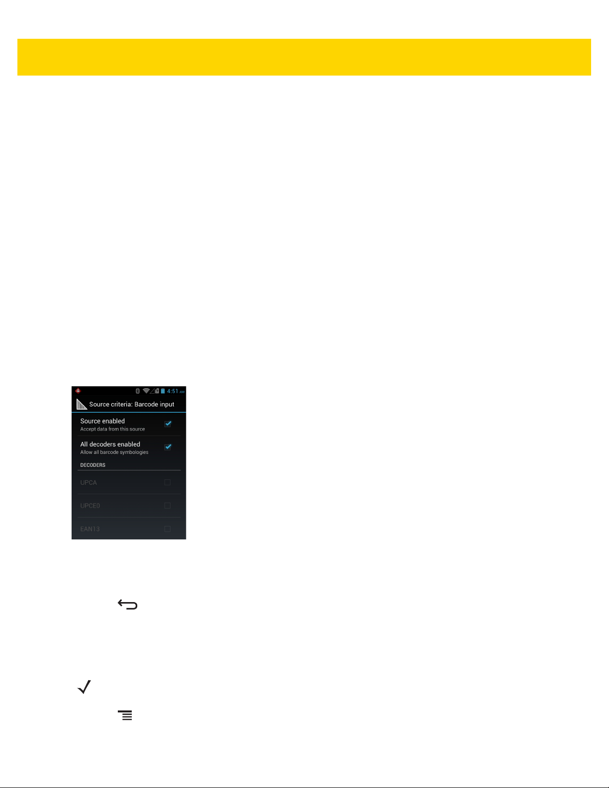
4 - 28 MC67 with Android™ OS Integrator Guide
2. Touch String to check for option to specify the string that must be present in the data.
3. In the Enter the string to check for dialog box, enter the string.
4. Touch OK.
5. Touch String position option to specify the position of the string specified in the String to check for option.
The ADF rule is only applied if the specific string in String to check for is found at the specified String
position location (zero for the start of the string).
6. Touch the + or - to change the value.
7. Touch OK.
8. Touch String length option to specify a length for the received data. The ADF rule only applies to the bar code
data with that specified length.
9. Touch the + or - to change the value.
10. Touch OK.
11. Touch Source criteria option to associate an input device to an ADF rule. The ADF rule only applies to data
received from associated input devices.
12. Touch Barcode input or MSR input. Options vary depending upon the device configuration.
13. Touch the Source enabled checkbox to accept data from this source.
Figure 4-21 Barcode Input Screen
14. For Barcode inputs, touch the All decoders enabled checkbox to select all bar code symbologies. Deselect
the All decoders enabled checkbox to individually select the symbologies.
15. Press until the Rule screen appears.
16. If required, repeat steps to create another rule.
Defining an Action
NOTE By default the Send remaining action is in the Actions list.
1. Press .
2. Touch New action.

DataWedge Configuration 4 - 29
3. In the New action menu, select an action to add to the Actions list. See Table 4-1 on page 4-29 for a list of
supported ADF actions.
4. Some Actions require additional information. Touch the Action to display additional information fields.
5. Repeat steps to create more actions.
6. Press .
Deleting a Rule
1. Touch and hold on a rule until the context menu appears.
2. Touch Delete rule to delete the rule from the Rules list.
When there is no rule available for ADF plug-in or all rules are disabled, DataWedge passes decoded data to
the output plug-in without processing the data.
Order Rules List
NOTE When there are no rules defined, ADF passes the captured data through as is. In contrast, when rules are
defined but all are disabled, ADF does not pass any captured data through.
Rules are processed in top-down order. The rules that are on top of the list are processed first. Use the icon next to
the rule to move it to another position in the list.
Table 4-1 ADF Supported Actions
Type Actions Description
Cursor
Movement
Skip ahead Moves the cursor forward by a specified number of characters. Enter
the number of characters to move the cursor ahead.
Skip back Moves the cursor back by a specified number of characters. Enter the
number of characters to move the cursor back.
Skip to start Moves the cursor to the beginning of the data.
Move to Moves the cursor forward until the specified string is found. Enter the
string in the data field.
Move past a Moves the cursor forward past the specified string. Enter the string in
the data field.

4 - 30 MC67 with Android™ OS Integrator Guide
Table 4-1 ADF Supported Actions (Continued)
Type Actions Description
Data
Modification
Crunch spaces Remove spaces between words to one and remove all spaces at the
beginning and end of the data.
Stop space crunch Stops space crunching. This disables the last Crunch spaces action.
Remove all spaces Remove all spaces in the data.
Stop space removal Stop removing spaces. This disables the last Remove all spaces
action.
Remove leading zeros Remove all zeros at the beginning of data.
Stop zero removal Stop removing zeros at the beginning of data. This disables the
previous Remove leading zeros action.
Pad with zeros Left pad data with zeros to meet the specified length. Enter the
number zeros to pad.
Stop pad zeros Stop padding with zeros. This disables the previous Pad with zeros
action.
Pad with spaces Left pad data with spaces to meet the specified length. Enter the
number spaces to pad.
Stop pad spaces Stop padding with spaces. This disables the previous Pad with
spaces action.
Replace string Replaces a specified string with a new string. Enter the string to
replace and the string to replace it with.
Stop all replace string Stop all Replace string actions.
Data
Sending
Send next Sends the specified number of characters from the current cursor
position. Enter the number of characters to send.
Send remaining Sends all data that remains from the current cursor position.
Send up to Sends all data up to a specified string. Enter the string.
Send pause Pauses the specified number of milliseconds before continuing the
next action. Enter the amount of time in milliseconds.
Send string Sends a specified string. Enter the string to send.
Send char Sends a specified ASCII/ Unicode character. Enter a character value.
The maximum Unicode character value can be entered is U-10FFFF
(= 1114111 in decimal).
Deleting an Action
1. Touch and hold the action name.
2. Select Delete action from the context menu.

ADF Example
The following illustrates an example of creating Advanced Data Formatting:
When a user scans a bar code with the following criteria:
•
Code 39 bar code.
•
length of 12 characters.
•
contains 129 at the start position.
Modify the data as follows:
•
Pad all sends with zeros to length 8.
•
send all data up to character X.
•
send a space character.
To create an ADF rule for the above example:
1. Touch .
DataWedge Configuration 4 - 31
2. Touch DataWedge.
3. Touch Profile0.
4. Under Keystroke Output, touch Advanced data formatting.
5. Touch Enable.
6. Touch Rule0.
7. Touch Criteria.
8. Touch String to check for.
9. In the Enter the string to check for text box, enter 129 and then touch OK.
10. Touch String position.
11. Change the value to 0.
12. Touch OK.
13. Touch String length.
14. Change value to 12.
15. Touch OK.
16. Touch Source criteria.
17. Touch Barcode input.
18. Touch All decoders enabled to disable all decoders.
19. Touch Code 39.
20. Press three times.
21. Touch and hold on the Send remaining rule until a menu appears.

4 - 32 MC67 with Android™ OS Integrator Guide
22. Touch Delete action.
23. Press .
24. Touch New action.
25. Select Pad with zeros.
26. Touch the Pad with zeros rule.
27. Touch How many.
28. Change value to 8 and then touch OK.
29. Press .
30. Press .
31. Touch New action.
32. Select Send up to.
33. Touch Send up to rule.
34. Touch String.
35. In the Enter a string text box, enter X.
36. Touch OK.
37. Press .
38. Press .
39. Touch New action.
40. Select Send char.
41. Touch Send char rule.
42. Touch Character code.
43. In the Enter character code text box, enter 32.
44. Touch OK.
45. Press .
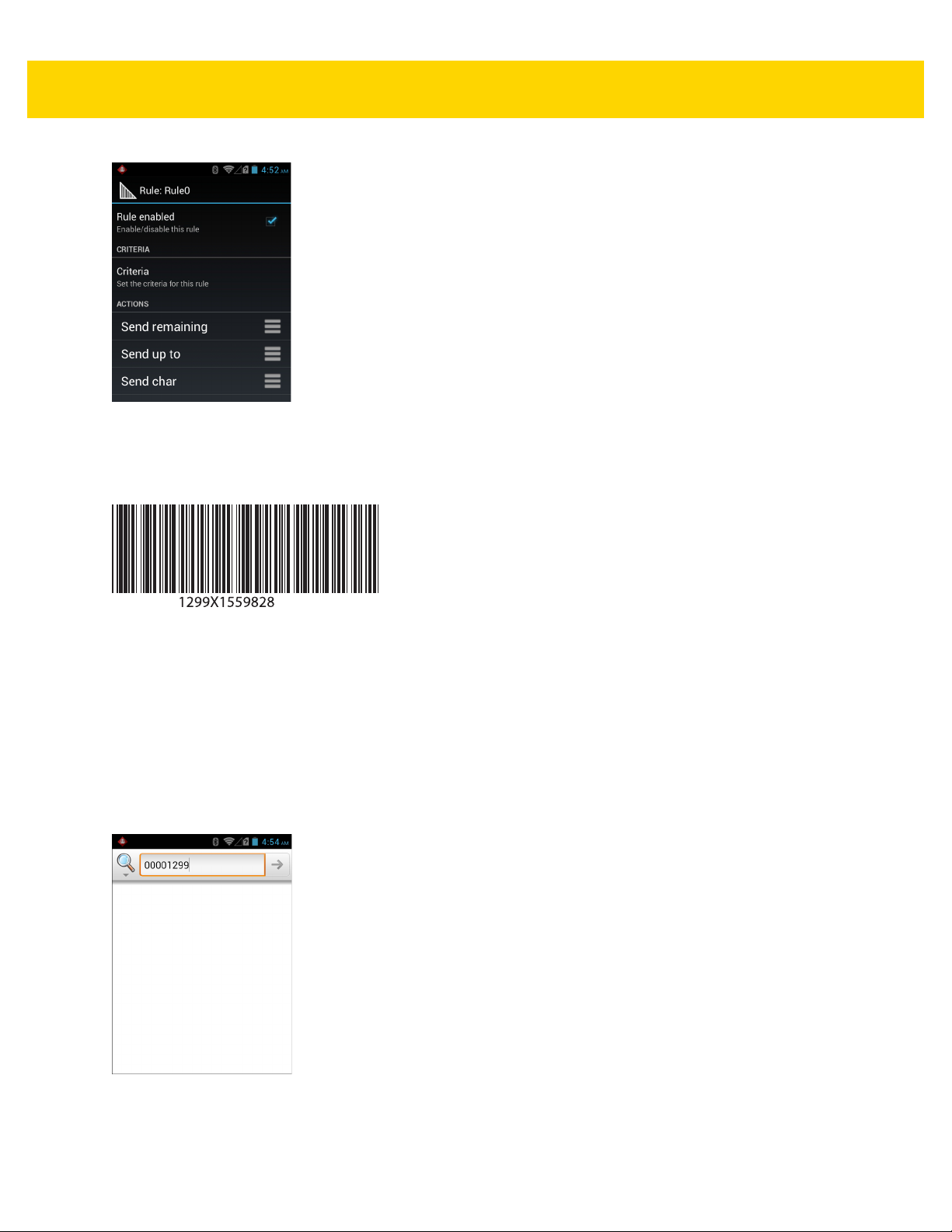
DataWedge Configuration 4 - 33
Figure 4-22 ADF Sample Screen
46. Ensure that an application is open on the device and a text field is in focus (text cursor in text field).
47. Aim the exit window at the bar code.
Figure 4-23 Sample Bar Code
48. Press and hold the scan button.
The red laser aiming pattern turns on to assist in aiming. Ensure that the bar code is within the area formed by
the aiming pattern. The LED light red to indicate that data capture is in process.
49. The LED lights green, a beep sounds and the device vibrates, by default, to indicate the bar code was decoded
successfully.The LED lights green and a beep sounds, by default, to indicate the bar code was decoded
successfully. The formatted data 000129X<space>appears in the text field.
Scanning a Code 39 bar code of 1299X15598 does not transmit data (rule is ignored) because the bar code
data did not meet the length criteria.
Figure 4-24 Formatted Data

4 - 34 MC67 with Android™ OS Integrator Guide
DataWedge Settings
The DataWedge Settings screen provides access to general, non-profile related options. Touch > Settings.
Figure 4-25 DataWedge Settings Window
•
DataWedge enabled - Enables or disables DataWedge. To disable DataWedge uncheck this option.
•
Enable logging - Enables or disables debug output file to logcat. To enable logging check this option.
•
Import - allows import of a DataWedge configuration file. The imported configuration replaces the current
configuration.
•
Export - allows export of the current DataWedge configuration to the microSD card.
•
Import Profile - allows import of a DataWedge profile file.
•
Export Profile - allows export of a DataWedge profile.
•
Restore - return the current configuration back to factory defaults.
Importing a Configuration File
1. Copy the configuration file to the root of the microSD card.
2. Touch > .
3. Press .
4. Touch Settings.
5. Touch Import.
6. Touch SD Card.
7. Touch Import. The configuration file (datawedge.db) is imported and replaces the current configuration.
Exporting a Configuration File
1. Touch > .
2. Press .

DataWedge Configuration 4 - 35
3. Touch Settings.
4. Touch Export.
5. Touch SD Card.
6. Touch Export. The configuration file (datawedge.db) is saved to the root of the microSD card.
Importing a Profile File
NOTE Do not change the filename of the of the profile file. If the filename is changed, the file will not be imported.
1. Copy the profile file to the root of the microSD card.
2. Touch > .
3. Press .
4. Touch Settings.
5. Touch Import Profile.
6. Touch the profile file to import.
7. Touch Import. The profile file (dwprofile_x.db, where x = the name of the profile) is imported and appears in
the profile list.
Exporting a Profile
1. Touch > .
2. Press .
3. Touch Settings.
4. Touch Export Profile.
5. Touch the profile to export.
6. Touch Export.
7. Touch Export. The profile file (dwprofile_x.db, where x = name of the profile) is saved to the root of the
microSD card.
Restoring DataWedge
To restore DataWedge to the factory default configuration:
1. Touch > .
2. Press .
3. Touch Settings.
4. Touch Restore.

4 - 36 MC67 with Android™ OS Integrator Guide
5. Touch Yes.
Configuration and Profile File Management
The configuration or profile settings for DataWedge can be saved to a file for distribution to other devices.
After making configuration or profile changes, export the new configuration or profile to the root of the microSD
card. The configuration file created is automatically named
named
devices and imported into DataWedge on those devices. Importing a configuration or profile replaces the existing
settings.
dwprofile_x.db, where x is the profile name. The files can then the copied to the microSD card of other
Enterprise Folder
Internal storage contains the Enterprise folder (/enterprise). The Enterprise folder is persistent and maintains
data after an Enterprise reset. After an Enterprise Reset, DataWedge checks folder
/enterprise/device/settings/datawedge/enterprisereset/ for a configuration file, datawedge.db or a
profile file,
dwprofile_x.db. If the file is found, it imports the file to replace any existing configuration or profile.
datawedge.db. The profile file created is automatically
NOTE A Factory Reset deletes all files in the Enterprise folder.
Auto Import
DataWedge supports remote deployment of a configuration to a device, using MDM tools. DataWedge monitors the
/enterprise/device/settings/datawedge/autoimport folder for the DataWedge configuration file
(
datawedge.db) or a profile file (dwprofile_x.db). When DataWedge launches it checks the folder. If a
configuration or profile file is found, it imports the file to replace any existing configuration or profile. Once the file
has been imported it is deleted from the folder.
While DataWedge is running it receives a notification from the system that a file has been placed into the
/enterprise/device/settings/datawedge/autoimport folder. When this occurs, DataWedge imports this
new configuration or profile, replacing the existing one and delete the file. DataWedge begins using the imported
configuration immediately.
NOTE A Factory Reset deletes all files in the Enterprise folder.
It is strongly recommended that the user exits DataWedge before remotely deploying any configuration or
profile. It is required that the file permissions are set to 666.
Programming Notes
The following paragraphs provide specific programming information when using DataWedge.
Overriding Trigger Key in an Application
To override the trigger key in an application, create a profile for the application that disables the Barcode input. In
the application, use standard APIs, such as onKeyDown() to listen for the KEYCODE_BUTTON_L1 and
KEYCODE_BUTTON_R1 presses.

Capture Data and Taking a Photo in the Same Application
To be able to capture bar code data and take a photo in the same application:
•
Create a Datawedge profile pertaining to the picture taking Activity in your application that disables scanning
and use standard Android SDK APIs to control the Camera.
•
The default Datawedge profile takes care of the scanning in the application. You might want to create another
DataWedge profile that caters to any specific scanning needs, associated to your Application's Activity
pertaining to scanning.
Disable DataWedge on MC67 and Mass Deploy
To disable DataWedge and deploy onto multiple MC67 devices:
1. Touch .
2. Touch DataWedge.
3. Press .
4. Touch Settings.
DataWedge Configuration 4 - 37
5. Unselect the DataWedge enabled check box.
6. Export the DataWedge configuration. See Exporting a Configuration File on page 4-34 for instructions. See
Configuration and Profile File Management on page 4-36 for instructions for using the auto import feature.
Soft Scan Feature
DataWedge allows a native Android application to programmatically start, stop, or toggle the scan trigger state. The
application can issue an Android Broadcast Intent, to control the scanner, without requiring the scan button to be
pressed. The active DataWedge profile is required to control all the parameters during a scan operation.
The structure of the broadcast intent that resolves to the soft scan is:
action: “com.symbol.emdk.datawedge.api.ACTION_SOFTSCANTRIGGER”
extras: This is a String name/value pair that contains trigger state details.
name: “com.symbol.emdk.datawedge.api.EXTRA_PARAMETER”
value: “START_SCANNING” or “STOP_SCANNING” or “TOGGLE_SCANNING”
Sample
Intent sendIntent = new Intent();
sendIntent.setAction(“com.symbol.emdk.datawedge.api.ACTION_SOFTSCANTRIGGER”);
sendIntent.putExtra(“com.symbol.emdk.datawedge.api.EXTRA_PARAMETER”, “TOGGLE_SCANNING”);
sendBroadcast(sendIntent);

4 - 38 MC67 with Android™ OS Integrator Guide

CHAPTER 5 ADMINISTRATOR
UTILITIES
We provide a suite of utilities that allow an administrator to manage the following features:
•
Multi-user Login - The Multi-user Login feature allows an administrator to set up the device to be used by
multiple users. The users have access to specific applications and features depending upon the user
settings.
•
Application Lock - The Application Lock feature allows an administrator to restrict application access for
specific applications by user or groups of users. The permitted applications are managed using groups of
user accounts from Multi-user Login feature.
•
Secure Storage - Secure Storage Administrator application allows installation and deletion of encrypted keys
and creation, mounting, un-mounting and deletion of the encrypted file systems.
The following applications help the administrator configure these features.
•
On-device applications - reside on the device.
• MultiUser Administrator
• AppLock Administrator
• Secure Storage Administrator.
•
Host computer application - reside on a host computer.
• Enterprise Administrator.
Required Software
These tools are available on the Support Central web site at http://www.zebra.com/support. Download the required
files from the Support Central web site and follow the installation instruction provided.
On-device Application Installation
See Application Installation on page 7-3 for instruction on installing applications onto the device.

5 - 2 MC67 with Android™ OS Integrator Guide
Multi-user/AppLock Configuration
To use the Multi-user Login and Application Lock features, the administrator must create user and group account
information using the Enterprise Administrator application.
NOTE The administrator can also create the account information manually. See Manual File Configuration on
page 5-11 for more information.
Enterprise Administrator Application
NOTE .Net Compact Framework 4 or later is required to run the Enterprise Administrator. To download, go to
www.microsoft.com.
Use the Enterprise Administrator application to setup user and group accounts and create the required (Password,
Group and White List) files for using the Multi-user and Application Lock features.
On the host computer launch the Enterprise Administrator application.
Figure 5-1 Enterprise Administrator Window
Creating Users
Each person that uses the device has to have a user name and password. To create a user:
1. Click + above the Users list box.
 Loading...