

Page 1

MC67
USER GUIDE
Page 2

Page 3

MC67
USER GUIDE
72E-161697-06
Rev. A
March 2019
Page 4

ii MC67 User Guide
No part of this publication may be reproduced or used in any form, or by any electrical or mechanical means,
without permission in writing from Zebra. This includes electronic or mechanical means, such as photocopying,
recording, or information storage and retrieval systems. The material in this manual is subject to change
without notice.
The software is provided strictly on an “as is” basis. All software, including firmware, furnished to the user is on
a licensed basis. Zebra grants to the user a non-transferable and non-exclusive license to use each software
or firmware program delivered hereunder (licensed program). Except as noted below, such license may not be
assigned, sublicensed, or otherwise transferred by the user without prior written consent of Zebra. No right to
copy a licensed program in whole or in part is granted, except as permitted under copyright law. The user shall
not modify, merge, or incorporate any form or portion of a licensed program with other program material, create
a derivative work from a licensed program, or use a licensed program in a network without written permission
from Zebra. The user agrees to maintain Zebra’s copyright notice on the licensed programs delivered
hereunder, and to include the same on any authorized copies it makes, in whole or in part. The user agrees not
to decompile, disassemble, decode, or reverse engineer any licensed program delivered to the user or any
portion thereof.
Zebra reserves the right to make changes to any software or product to improve reliability, function, or design.
Zebra does not assume any product liability arising out of, or in connection with, the application or use of any
product, circuit, or application described herein.
No license is granted, either expressly or by implication, estoppel, or otherwise under any Zebra Technologies
Corporation, intellectual property rights. An implied license only exists for equipment, circuits, and subsystems
contained in Zebra products.
Page 5

Revision History
Changes to the original guide are listed below:
Change Date Description
-01 Rev. A 09/19/12 Initial release.
-02 Rev. A 08/30/13 Add CDMA WAN support.
-03 Rev. A 06/30/14 Add support for Ortus display. Changes due to OEM version 03.46.36 (ALC,
-04 Rev. A 03/11/15 Zebra Rebranding.
-05 Rev. A 09/30/15 Add MC67NA Base Model Configuration.
-06 Rev. A 3/2019 Update cleaning procedures.
iii
keylight registry settings, red LED during scanning disabled).
Page 6

iv MC67 User Guide
Page 7

TABLE OF CONTENTS
Revision History.............................................................................................................................. iii
About This Guide
Introduction ..................................................................................................................................... xiii
Documentation Set ................................................................................................................... xiii
Configurations................................................................................................................................. xiv
Software Versions..................................................................................................................... xiv
Chapter Descriptions ...................................................................................................................... xv
Notational Conventions................................................................................................................... xv
Related Documents ........................................................................................................................ xvi
Service Information......................................................................................................................... xvi
Chapter 1: Getting Started
Introduction .................................................................................................................................... 1-1
Unpacking ...................................................................................................................................... 1-1
Getting Started ............................................................................................................................... 1-2
Installing a microSD Card ........................................................................................................ 1-2
Installing the SIM Card ............................................................................................................. 1-3
Installing the Battery ................................................................................................................ 1-4
Charging the Battery ................................................................................................................ 1-5
Charging the Main Battery ................................................................................................. 1-5
Charging Spare Batteries ................................................................................................... 1-6
Charging Temperature ....................................................................................................... 1-6
Powering On the MC67 ............................................................................................................ 1-6
Calibrating the Screen ........................................................................................................ 1-7
Checking Battery Status ................................................................................................................ 1-7
Replacing the Battery ..................................................................................................................... 1-7
Replacing the microSD Card ......................................................................................................... 1-8
Replacing the SIM Card ................................................................................................................. 1-8
Battery Management ...................................................................................................................... 1-9
Changing the Power Settings .................................................................................................. 1-9
Changing the Backlight Settings .............................................................................................. 1-10
Changing the Keypad Backlight Settings ................................................................................. 1-10
Page 8

vi MC67 User Guide
Turning Off the Radios ............................................................................................................. 1-10
Network Activation ......................................................................................................................... 1-10
Activating an MC67ND on a CDMA Network ........................................................................... 1-10
Switching from CDMA to GSM/UMTS ..................................................................................... 1-11
Switching from GSM/UTMS to CDMA ..................................................................................... 1-12
Chapter 2: Using the MC67
Introduction .................................................................................................................................... 2-1
Features ......................................................................................................................................... 2-1
LED Indicators ............................................................................................................................... 2-2
Keypads ......................................................................................................................................... 2-3
Finger Scrolling .............................................................................................................................. 2-4
Home Screen ................................................................................................................................. 2-4
Classic Today Screen .............................................................................................................. 2-6
Status Bar ................................................................................................................................ 2-7
Tile Bar ..................................................................................................................................... 2-10
Adjusting Volume ........................................................................................................................... 2-12
Resetting the MC67 ....................................................................................................................... 2-12
Performing a Warm Boot ......................................................................................................... 2-12
Performing a Cold Boot ............................................................................................................ 2-12
Locking the MC67 .......................................................................................................................... 2-12
Un-locking with Simple PIN ...................................................................................................... 2-13
Un-locking with Strong Password ............................................................................................ 2-13
Battery Status Indications .............................................................................................................. 2-14
Battery Reserve Options .......................................................................................................... 2-15
Main Battery Temperature Notifications ................................................................................... 2-16
Interactive Sensor Technology ...................................................................................................... 2-17
Power Management ................................................................................................................. 2-17
Display Orientation ................................................................................................................... 2-17
Free Fall Detection ................................................................................................................... 2-17
Stylus ............................................................................................................................................. 2-18
Entering Data ................................................................................................................................. 2-18
Using Voice-Over-IP ...................................................................................................................... 2-19
Chapter 3: Data Capture
Introduction .................................................................................................................................... 3-1
Imaging .......................................................................................................................................... 3-1
Operational Modes ................................................................................................................... 3-1
Digital Camera ............................................................................................................................... 3-2
Scanning Considerations ............................................................................................................... 3-2
Imager Scanning ............................................................................................................................ 3-2
Digital Camera Scanning ............................................................................................................... 3-4
Using the RS507 Hands-free Imager ............................................................................................. 3-4
DataWedge .................................................................................................................................... 3-5
Enable DataWedge .................................................................................................................. 3-5
Disable DataWedge ................................................................................................................. 3-5
Taking Pictures .............................................................................................................................. 3-6
Burst Mode ............................................................................................................................... 3-6
Timer Mode .............................................................................................................................. 3-6
Page 9

Table of Contents vii
Editing Pictures ........................................................................................................................ 3-7
Setting a Picture as Wallpaper ................................................................................................. 3-7
Camera Configuration .............................................................................................................. 3-7
Recording a Video ......................................................................................................................... 3-8
Video Configuration ................................................................................................................. 3-8
Viewing Pictures and Videos ......................................................................................................... 3-9
Customizing Pictures & Videos ...................................................................................................... 3-9
Chapter 4: Making Calls
Introduction .................................................................................................................................... 4-1
Making a Call ................................................................................................................................. 4-1
Using the Phone Keypad ......................................................................................................... 4-1
Smart Dialing ........................................................................................................................... 4-2
Using Contacts ......................................................................................................................... 4-3
Using Call History .................................................................................................................... 4-3
Making a Speed Dial Call ......................................................................................................... 4-4
Answering a Call ............................................................................................................................ 4-4
Incoming Call Features ............................................................................................................ 4-5
Missed Call Notification .................................................................................................................. 4-5
Emergency Calling ......................................................................................................................... 4-5
Audio Modes .................................................................................................................................. 4-6
Using a Bluetooth Headset ...................................................................................................... 4-6
Adjusting Audio Volume ........................................................................................................... 4-6
Muting a Call .................................................................................................................................. 4-6
Taking Notes .................................................................................................................................. 4-6
Using Call History .......................................................................................................................... 4-7
Managing Call History .............................................................................................................. 4-7
Changing the Call History View .......................................................................................... 4-7
Resetting the Recent Calls Counter ................................................................................... 4-8
Deleting All Call History Items ............................................................................................ 4-8
Viewing Call Status ............................................................................................................ 4-8
Using the Call History Menu ............................................................................................... 4-9
Conference Calling ........................................................................................................................ 4-10
Making a 3-way Call ....................................................................................................................... 4-10
Swapping Calls (GSM/UMTS) ....................................................................................................... 4-11
Swapping Calls (CDMA) ................................................................................................................ 4-12
Speed Dial Setup ........................................................................................................................... 4-12
Adding a Speed Dial Entry ....................................................................................................... 4-13
Editing a Speed Dial Entry ....................................................................................................... 4-15
Deleting a Speed Dial Entry ..................................................................................................... 4-15
Chapter 5: Using WLAN
Introduction .................................................................................................................................... 5-1
Fusion Overview ............................................................................................................................ 5-1
Connecting to the Internet ........................................................................................................ 5-2
Supported Applications .................................................................................................................. 5-2
Fusion Setup .................................................................................................................................. 5-3
Page 10

viii MC67 User Guide
Chapter 6: Messaging
Introduction .................................................................................................................................... 6-1
Email .............................................................................................................................................. 6-1
Creating an Email Message ..................................................................................................... 6-1
Viewing an Email Message ...................................................................................................... 6-1
Replying to a Message ............................................................................................................ 6-2
Text Messaging ............................................................................................................................. 6-2
Viewing Text Messages ........................................................................................................... 6-2
Sending a Text Message ......................................................................................................... 6-4
Using a Dual Line SIM ................................................................................................................... 6-5
Email Setup ................................................................................................................................... 6-6
Setting Up an IMAP or POP Account ....................................................................................... 6-6
Automatic Email Setup ....................................................................................................... 6-6
Manual Email Setup ........................................................................................................... 6-7
Entering Email Settings Manually ...................................................................................... 6-7
Editing an Email Account ......................................................................................................... 6-8
Setting Email Signatures .......................................................................................................... 6-9
Chapter 7: Bluetooth
Introduction .................................................................................................................................... 7-1
Adaptive Frequency Hopping ........................................................................................................ 7-1
Security .......................................................................................................................................... 7-2
Security Mode 3 (Link Level Encryption) ................................................................................. 7-2
Microsoft Bluetooth Stack .................................................................................................. 7-2
StoneStreet One Bluetooth Stack ...................................................................................... 7-2
FIPS 140-2 ............................................................................................................................... 7-3
Bluetooth Configuration ................................................................................................................. 7-3
Bluetooth Power States ................................................................................................................. 7-4
Cold Boot ........................................................................................................................... 7-4
Warm Boot ......................................................................................................................... 7-4
Suspend ............................................................................................................................. 7-4
Resume .............................................................................................................................. 7-4
MotoBTUI Application .................................................................................................................... 7-5
Device Information ................................................................................................................... 7-5
FIPS Configuration ................................................................................................................... 7-5
Device Status ........................................................................................................................... 7-6
Using Microsoft Bluetooth Stack .................................................................................................... 7-6
Turning the Bluetooth Radio Mode On and Off ...................
Enabling Bluetooth ............................................................................................................. 7-7
Disabling Bluetooth ............................................................................................................ 7-7
Discovering Bluetooth Device(s) .............................................................................................. 7-8
Available Services .................................................................................................................... 7-10
Object Push Services via Beam ......................................................................................... 7-10
Internet Sharing ................................................................................................................. 7-12
Serial Port Services ........................................................................................................... 7-13
ActiveSync Using Serial Port Services .............................................................................. 7-13
Phone Book Access Profile Services ................................................................................. 7-14
Using Bluetooth StoneStreet One Bluetooth Stack ....................................................................... 7-16
Turning the Bluetooth Radio Mode On and Off ........................................................................ 7-16
Disabling Bluetooth ............................................................................................................ 7-16
..................................................... 7-6
Page 11

Table of Contents ix
Enabling Bluetooth ............................................................................................................. 7-16
Modes ...................................................................................................................................... 7-16
Wizard Mode ...................................................................................................................... 7-16
Explorer Mode .................................................................................................................... 7-16
Discovering Bluetooth Device(s) .............................................................................................. 7-17
Available Services .................................................................................................................... 7-20
File Transfer Services ........................................................................................................ 7-20
Connecting to the Internet Using an Access Point ............................................................. 7-22
Dial-Up Networking Services ............................................................................................. 7-22
Add a Dial-up Entry ............................................................................................................ 7-24
Object Exchange Push Services ........................................................................................ 7-25
Headset Services ............................................................................................................... 7-28
Serial Port Services ............................................................................................................ 7-29
ActiveSync Using Serial Port Services ............................................................................... 7-29
Personal Area Network Services ....................................................................................... 7-31
A2DP/AVRCP Services ...................................................................................................... 7-31
Connect to a HID Device .................................................................................................... 7-32
Pairing with Discovered Device(s) ........................................................................................... 7-32
Bluetooth Settings .................................................................................................................... 7-34
Device Info ......................................................................................................................... 7-34
Services ............................................................................................................................. 7-34
Security .............................................................................................................................. 7-39
Discovery ........................................................................................................................... 7-39
Virtual COM Port ................................................................................................................ 7-40
HID ..................................................................................................................................... 7-40
Profiles ............................................................................................................................... 7-41
System Parameters ............................................................................................................ 7-41
Miscellaneous .................................................................................................................... 7-41
Chapter 8: Using GPS Navigation
Introduction .................................................................................................................................... 8-1
Software Installation ....................................................................................................................... 8-1
MC67 GPS Setup .......................................................................................................................... 8-1
Operation ....................................................................................................................................... 8-2
GPS Maps on microSD Cards ................................................................................................. 8-2
Answering a Phone Call While Using GPS .............................................................................. 8-2
Losing the GPS Signal While in a Vehicle ............................................................................... 8-2
Assisted GPS .................................................................................................................
Chapter 9: Settings
Settings Folder ............................................................................................................................... 9-1
Locking the MC67 .......................................................................................................................... 9-4
Power Settings ............................................................................................................................... 9-4
Backlight Settings .......................................................................................................................... 9-5
Keypad Backlight Settings ............................................................................................................. 9-5
USB Configuration ......................................................................................................................... 9-5
UI Settings ..................................................................................................................................... 9-6
Start Screen Settings ............................................................................................................... 9-6
IE Zoom Mapping ..................................................................................................................... 9-6
................ 8-2
Page 12

x MC67 User Guide
IST Settings ................................................................................................................................... 9-8
Info Tab .................................................................................................................................... 9-8
Display Tab .............................................................................................................................. 9-8
Power Management Tab .......................................................................................................... 9-8
On Face Down ................................................................................................................... 9-9
Keep Alive On Motion ........................................................................................................ 9-9
Setting Sensitivity ............................................................................................................... 9-9
Events Tab ............................................................................................................................... 9-10
Sensors Tab ............................................................................................................................. 9-10
Chapter 10: Accessories
Introduction .................................................................................................................................... 10-1
Accessories ................................................................................................................................... 10-1
Single Slot USB Cradle .................................................................................................................. 10-3
Charging the MC67 Battery ..................................................................................................... 10-3
Charging the Spare Battery ..................................................................................................... 10-4
Battery Charging Indicators ..................................................................................................... 10-4
Charging Temperature ....................................................................................................... 10-4
Single-slot Ethernet/Modem/USB Cradle ...................................................................................... 10-5
Country Settings ...................................................................................................................... 10-5
Connection Setup .................................................................................................................... 10-5
Indicators ................................................................................................................................. 10-6
Operation ................................................................................................................................. 10-6
Ethernet Connection .......................................................................................................... 10-6
Modem Connection ............................................................................................................ 10-6
Four Slot Charge Only Cradle ....................................................................................................... 10-7
Charging .................................................................................................................................. 10-7
Battery Charging Indicators ..................................................................................................... 10-7
Charging Temperature ....................................................................................................... 10-7
Four Slot Ethernet Cradle .............................................................................................................. 10-8
Charging .................................................................................................................................. 10-8
Communication ........................................................................................................................ 10-9
LED Indicators (CRD5500-4000ER) .................................................................................. 10-9
LED Indicators (CRD5501-4000ER) .................................................................................. 10-9
Magnetic Stripe Reader ................................................................................................................. 10-10
Attaching and Removing the MSR ........................................................................................... 10-10
Using the MSR ......................................................................................................................... 10-10
VCD5000 Vehicle Cradle ............................................................................................................... 10-12
Charging the MC67 Battery ..................................................................................................... 10-12
Removing the MC67 .......................................................................................................... 10-12
Battery Charging Indicators ..................................................................................................... 10-13
Charging Temperature ....................................................................................................... 10-13
Four Slot Battery Charger .............................................................................................................. 10-14
Battery Charging ..................................................................................................................... 10-14
Battery Charging Indicators ..................................................................................................... 10-14
Charging Temperature ....................................................................................................... 10-14
Cables ............................................................................................................................................ 10-15
Battery Charging and Operating Power ................................................................................... 10-15
LED Charge Indications ........................................................................................................... 10-16
Charging Temperature ....................................................................................................... 10-16
Page 13

Table of Contents xi
Trigger Handle ............................................................................................................................... 10-17
Inserting the MC67 into the Trigger Handle ............................................................................. 10-17
Removing the MC67 ................................................................................................................ 10-17
Scanning .................................................................................................................................. 10-17
Using the RS507 Hands-free Imager ............................................................................................. 10-19
Chapter 11: Maintenance & Troubleshooting
Introduction .................................................................................................................................... 11-1
Maintaining the MC67 .................................................................................................................... 11-1
Removing the Screen Protector ..................................................................................................... 11-2
Battery Safety Guidelines .............................................................................................................. 11-2
Cleaning ......................................................................................................................................... 11-3
Harmful Ingredients .................................................................................................................. 11-4
Cleaning Instructions ............................................................................................................... 11-4
Special Cleaning Notes ............................................................................................................ 11-4
Materials Required ................................................................................................................... 11-4
Cleaning the MC67 .................................................................................................................. 11-4
Housing .............................................................................................................................. 11-4
Display ............................................................................................................................... 11-5
Scanner Exit Window ......................................................................................................... 11-5
Connector ........................................................................................................................... 11-5
Cleaning Cradle Connectors .................................................................................................... 11-5
Cleaning Frequency ................................................................................................................. 11-6
Troubleshooting ............................................................................................................................. 11-6
MC67 ....................................................................................................................................... 11-6
Single Slot USB Cradle ............................................................................................................ 11-9
Four Slot Ethernet Cradle ........................................................................................................ 11-10
Vehicle Cradle .......................................................................................................................... 11-10
Four Slot Battery Charger ........................................................................................................ 11-11
Cables ...................................................................................................................................... 11-11
Magnetic Stripe Reader ........................................................................................................... 11-12
Appendix A: Technical Specifications
MC67 ............................................................................................................................................. A-1
Appendix B: Keypads
Introduction .................................................................................................................................... B-1
Numeric Keypad Configuration ................................................................................................ B-1
Alpha-numeric Keypad Configurations .................................................................................... B-5
PIM Keypad Configuration ....................................................................................................... B-13
DSD Keypad Configuration ...................................................................................................... B-15
Special Character Key ............................................................................................................. B-18
Calculator DSD Keypad Configuration ..................................................................................... B-20
Glossary
Page 14

xii MC67 User Guide
Index
Page 15

ABOUT THIS GUIDE
Introduction
This guide provides information about using the MC67 mobile computer and accessories.
NOTE Screens and windows pictured in this guide are samples and can differ from actual screens.
Documentation Set
The documentation set for the MC67 provides information for specific user needs, and includes:
•
MC67 Quick Start Guide - describes how to get the MC67 up and running.
•
MC67 User Guide - describes how to use the MC67.
•
MC67 Integrator Guide - describes how to set up the MC67 and accessories.
•
Enterprise Mobility Developer Kit (EMDK) Help File - provides API information for writing applications.
Page 16

xiv MC67 User Guide
Configurations
This guide covers the following configurations:
Configuration Radios Display Memory
MC67NA Base
Model
MC67NA WLAN: 802.11
MC67ND WLAN: 802.11
WAN: HSPA+
WLAN: 802.11
a/b/g/n
WPAN: Bluetooth
v2.1 EDR
GPS: Stand-alone
GPS or
A-GPS
a/b/g/n
WPAN: Bluetooth
v2.1 EDR
WWAN:GSM/UMTS
GPS: Stand-alone
GPS or
A-GPS
a/b/g/n
WPAN: Bluetooth
v2.1 EDR
WWAN:GSM/UMTS
or 1XRTT/
CDMA
GPS: Stand-alone
GPS or
A-GPS
3.5” VGA
Color
3.5” VGA
Color
3.5” VGA
Color
512 MB RAM/
2 GB Flash
512 MB RAM/
2 GB Flas h or
1 GB RAM/8
GB Flash
1 GB RAM/
8 GB Flash
Data
Capture
Options
2D imager or
2D imager
and camera
2D imager or
2D imager
and camera
2D imager or
2D imager
and camera
Operating
System
Windows
Embedded
Handheld 6.5
Windows
Embedded
Handheld 6.5
Windows
Embedded
Handheld 6.5
Keypads
Numeric,
QWERTY, or
Calculator DSD
Numeric,
QWERTY,
QWERTZ,
AZERTY, PIM
or DSD
Numeric,
QWERTY,
QWERTZ,
AZERTY or
DSD
Software Versions
This guide covers various software configurations and references are made to operating system or software
versions for:
•
Adaptation Kit Update (AKU) version
•
OEM version
•
Fusion software
•
Phone software.
AKU Version
To determine the Adaptation Kit Update (AKU) version:
Ta p > Settings > System > About > Version.
The second line lists the operating system version and the build number. The last part of the build number
represents the AKU number. For example, Build 29058.5.3.12.8 indicates that the device is running AKU
version 5.3.12.8.
OEM Version
To determine the OEM software version:
Page 17

Ta p > Settings > System > System Info > System.
Fusion Software
To determine the Fusion software version:
Ta p > Wireless Companion > Wireless Status > Versions.
Phone Software
To determine the Phone software version:
Press > > Phone information.
Chapter Descriptions
Topics covered in this guide are as follows:
•
Chapter 1, Getting Started provides information on getting the MC67 up and running for the first time.
About This Guide xv
•
Chapter 2, Using the MC67 provides basic instructions for using the MC67, including powering on and
resetting the MC67.
•
Chapter 3, Data Capture provides instructions for capturing data.
•
Chapter 4, Making Calls provides setup instructions for the MC67 phone.
•
Chapter 5, Using WLAN provides information for connection the MC67 to a WLAN.
•
Chapter 6, Messaging provides information for using Email, SMS and MMS messaging.
•
Chapter 7, Bluetooth explains Bluetooth functionality on the MC67.
•
Chapter 8, Using GPS Navigation provides information about GPS navigation with the MC67.
•
Chapter 9, Settings provides basic instructions for using the MC67 phone.
•
Chapter 10, Accessories describes the available accessories and how to use them with the MC67.
•
Chapter 11, Maintenance & Troubleshooting includes instructions on cleaning and storing the MC67, and
provides troubleshooting solutions for potential problems during MC67 operation.
•
Appendix A, Technical Specifications provides the technical specifications for the MC67.
•
Appendix B, Keypads Provides information on the various keypad configuration.
Notational Conventions
The following conventions are used in this document:
•
Mobile computer refers to the MC67 series of hand-held computers.
•
Italics are used to highlight the following:
• Chapters and sections in this and related documents
• Icons on a screen.
Page 18

xvi MC67 User Guide
•
Bold text is used to highlight the following:
• Dialog box, window, and screen names
• Drop-down list and list box names
• Check box and radio button names
• Key names on a keypad
• Button names on a screen.
•
Bullets (•) indicate:
• Action items
• Lists of alternatives
• Lists of required steps that are not necessarily sequential
•
Sequential lists (e.g., those that describe step-by-step procedures) appear as numbered lists.
Related Documents
•
MC67 Quick Start Guide, p/n 72-116172-xx.
•
MC67 Regulatory Guide, p/n 72-116171-xx.
•
MC67 Integrator Guide, p/n 72E-161698-xx.
•
Mobility Services Platform User Guide, p/n 72E-100158-xx.
•
Enterprise Mobility Developer Kits (EMDKs), available at: http://www.zebra.com/support.
•
Latest ActiveSync or Windows Mobile Device Center software, available at: http://www.microsoft.com.
For the latest version of this guide and all guides, go to: http://www.zebra.com/support
Service Information
If the user has a problem with the equipment, contact Zebra Global Customer Support in the region. Contact
information is available at: http://www.zebra.com/support
When contacting support, please have the following information available:
•
Serial number of the unit (found on manufacturing label)
•
Model number or product name (found on manufacturing label)
•
Software type and version number
•
IMEI number.
.
.
Page 19

About This Guide xvii
Manufacturing label
Zebra responds to calls by email, telephone or fax within the time limits set forth in support agreements.
If the problem cannot be solved by Zebra Global Customer Support, the user may need to return the
equipment for servicing and will be given specific directions. Zebra is not responsible for any damages incurred
during shipment if the approved shipping container is not used. Shipping the units improperly can possibly void
the warranty. Remove the SIM card and/or microSD card from the MC67 before shipping for service.
If the device was purchased from a Zebra business partner, contact that business partner for support.
Page 20

xviii MC67 User Guide
Page 21

CHAPTER 1 GETTING STARTED
Introduction
This chapter lists the parts and accessories for the MC67 and explains how to set up the MC67 for the first
time.
Unpacking
Carefully remove all protective material from the MC67 and save the shipping container for later storage and
shipping.
Verify that the following were received:
•
MC67 mobile computer
•
3600 mAh Lithium-ion battery
•
stylus with tether (installed)
•
Regulatory Guide
•
Quick Start Guide.
Inspect the equipment for damage. If any equipment is missing or damaged, contact the Zebra Global
Customer Support center immediately. See page xvi for contact information.
Prior to using the MC67 for the first time, remove the protective shipping film that covers the scan window,
display and camera window.
Page 22

1 - 2 MC67 User Guide
Rubber access door
microSD card holder door
SIM card holder door
Getting Started
To start using the MC67 for the first time:
1. Install a micro secure digital (SD) card (optional)
2. Install the subscriber identification module (SIM) card (GSM/UMTS only)
3. Install the battery.
4. Charge the MC67.
5. Power on the MC67.
Installing a microSD Card
The microSD card slot provides secondary non-volatile storage. The slot is located under the battery pack.
Refer to the documentation provided with the card for more information, and follow the manufacturer’s
recommendations for use.
CAUTION Follow proper electrostatic discharge (ESD) precautions to avoid damaging the microSD card. Proper
ESD precautions include, but are not limited to, working on an ESD mat and ensuring that the
operator is properly grounded.
To install the microSD card:
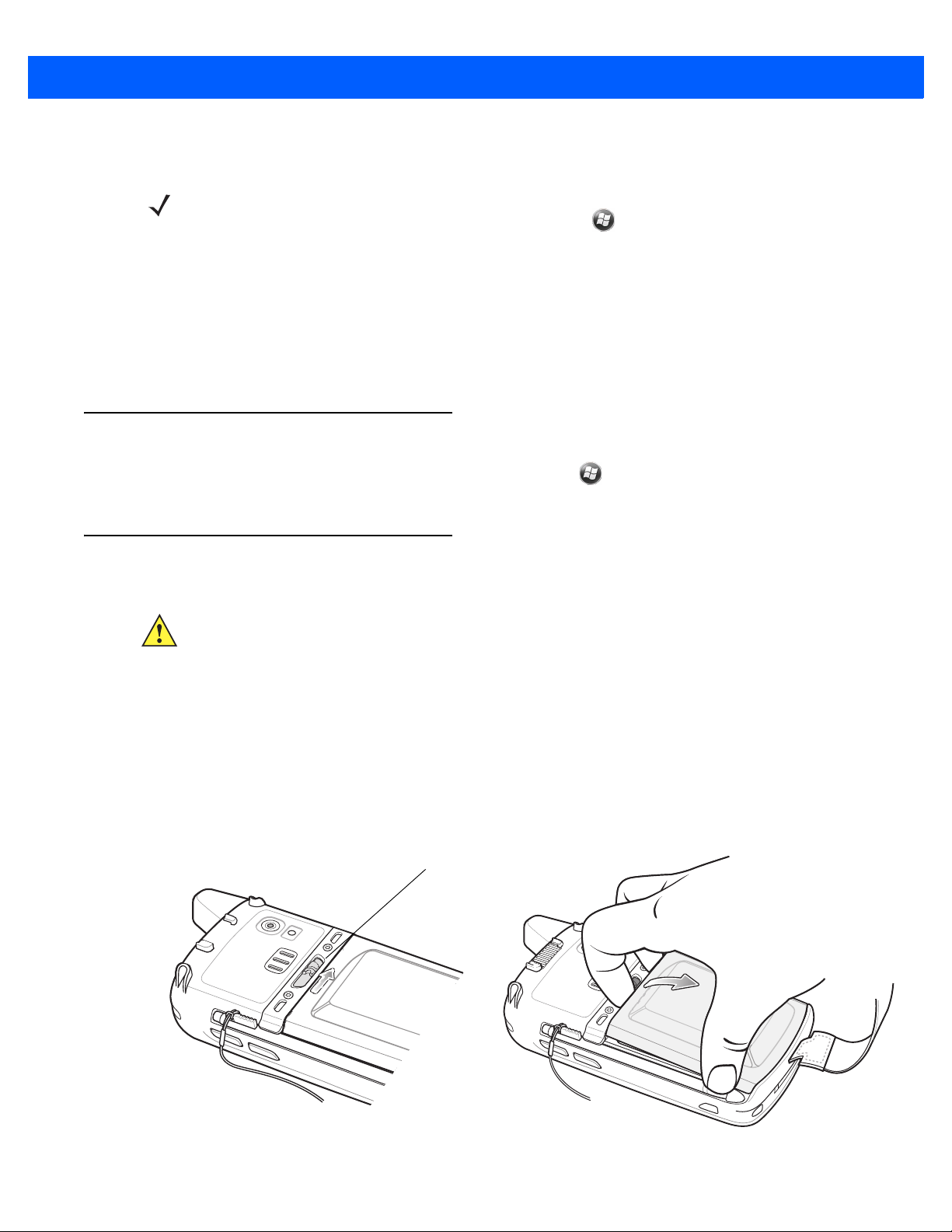
1. Remove the handstrap.
2. Lift the rubber access door.
3. Slide the SIM card holder door up to unlock.
4. Lift the SIM card holder door.
Figure 1-1
5. Lift the microSD card holder door.
6. Insert the microSD card into the card holder door ensuring that the card slides into the holding tabs on
Lift SIM Slot Holder Door
each side of the door.
Page 23

Getting Started 1 - 3
microSD card
Holding tab
Figure 1-2
7. Close the card holder door and push down until it is securely in place.
8. If installing a SIM card, proceed to Installing the SIM Card.
9. Close the SIM card holder door and slide down until it locks into place.
10. Close the rubber access door.
Insert microSD Card in Holder
Installing the SIM Card
NOTE GSM/UMTS networks only.
Global System for Mobile communications (GSM) phone service requires a SIM card. Obtain the card from a
service provider. The card fits into the MC67 and can contain the following information:
•
Mobile phone service provider account details.
•
Information regarding service access and preferences.
•
Contact information, which can be moved to Contacts on the MC67.
•
Any additional subscribed services.
NOTE For more information about SIM cards, refer to the service provider's documentation.
To install the SIM card:
1. Lift rubber access door.
2. Slide the SIM card holder up to unlock.
3. Lift the SIM card holder door.
Page 24

1 - 4 MC67 User Guide
Figure 1-3
4. Insert the SIM card, as shown in Fig ure 1-4 ensuring that the card slides into the holding tabs on each side
Lifting the SIM Cover
of the door.
Figure 1-4
5. Close the SIM card holder door and slide down to lock into place.
6. Close the rubber access door.
7. Install the battery.
Inserting the SIM Card
Installing the Battery
To install the battery.
1. Insert the battery, bottom first, into the battery compartment in the back of the MC67.
2. Press the battery down into the battery compartment until the battery release latch snaps (two clicks) into
place.
NOTE If the battery has significant charge, the MC67 turns on.
3. Replace the handstrap.
Page 25

Getting Started 1 - 5
Battery
Battery Release Latch
2
1
Figure 1-5
Inserting the Battery
Charging the Battery
CAUTION Ensure to follow the guidelines for battery safety described in Battery Safety Guidelines on page 11-2.
Charging the Main Battery
Before using the MC67 for the first time, charge the main battery until the amber Charging/Battery Status light
emitting diode (LED) remains lit (see Table 1-1 on page 1-6 for charge status indications). To charge the MC67,
use a cable or a cradle with the appropriate power supply. For information about the accessories available for
the MC67, see Chapter 10, Accessories.
The MC67 is equipped with a backup battery which automatically charges from the fully-charged main battery.
When using the MC67 for the first time, the backup battery requires approximately 40 hours to fully charge.
This is also true any time the backup battery is discharged, which occurs when the main battery is removed for
several hours. The backup battery retains random access memory (RAM) data in memory for at least 15
minutes (at room temperature) when the MC67’s main battery is removed. When the MC67 reaches a very low
battery state, the combination of main battery and backup battery retains RAM data in memory for at least 36
hours.
For cable and cradle setup and charging procedures refer to the MC67 Integrator Guide.
•
USB Charging Cable
•
Charge Only Cable
•
Single Slot USB Cradle
•
Four Slot Charge Only Cradle
•
Four Slot Ethernet Cradle.
Page 26

1 - 6 MC67 User Guide
To charge the main battery:
1. Connect the charging accessory to the appropriate power source.
2. Insert the MC67 into a cradle or attach to a cable. The MC67 begins charging. The Charging/Battery Status
LED blinks amber while charging, then turns solid amber when fully charged. See Table 1-1 for charging
indications.
The 3600 mAh battery charges in less than six hours.
Table 1-1
Off MC67 is not charging.
Slow Blinking Amber
(1 blink every 2 seconds)
Solid Amber Charging complete.
Fast Blinking Amber
(2 blinks/second)
LED Charge Indicators
Charging/Battery
Status LED
Indication
MC67 is not inserted correctly in the cradle or connected to a power source.
Charger/cradle is not powered.
MC67 is charging.
Note: When the battery is initially inserted in the MC67, the amber LED flashes
once if the battery power is low or the battery is not fully inserted.
Charging error, e.g.:
•
Temperature is too low or too high.
•
Charging has gone on too long without completion (typically eight
hours).
Charging Spare Batteries
See Chapter 10, Accessories for information on using accessories to change spare batteries.
Charging Temperature
Charge batteries in temperatures from 0 °C to 40 °C (32 °F to 104 °F). Note that charging is intelligently
controlled by the MC67.
To accomplish this, for small periods of time, the MC67 or accessory alternately enables and disables battery
charging to keep the battery at acceptable temperatures. The MC67 or accessory indicates when charging is
disabled due to abnormal temperatures via its LED. See Table 1-1.
Powering On the MC67
NOTE If during installation of the battery, the battery has significant charge the MC67 turns on.
Press the Power button to turn on the MC67. The splash screen displays for about a minute as the MC67
initializes its flash file system, then the calibration window appears.
Page 27
Calibrating the Screen
Battery Latch
NOTE The Calibration screen can be accessed by pressing Blue key then Backspace key.
On the Personal Information Manager (PIM) keypad, tap
Screen.
To calibrate the screen so the cursor on the touch screen aligns with the tip of the stylus:
1. Remove the stylus from its holder on the side of the MC67.
2. Carefully press and briefly hold the tip of stylus on the center of each target that appears on the screen.
3. Repeat as the target moves around the screen, then tap the screen to continue.
Checking Battery Status
To check the charge status of the main battery in the MC67, tap > Settings > Power to display the Power
window.
Getting Started 1 - 7
Settings > System > Screen > Align
Replacing the Battery
CAUTION The MC67 backup battery retains data for up to 15 minutes. Replace the battery within 15 minutes to
ensure that application states are maintained and that data is not lost.
1. If the MC67 is in a cradle, remove it before performing a Safe Battery Swap.
2. If the MC67 is in suspend mode, press the red Power button to wake the device.
3. Press the red Power button. The Power Action Key window appears.
4. Ta p Safe Battery Swap. The Data Capture LED lights red.
5. When the LED turns off, remove the handstrap.
6. Slide the battery latch to the right. The battery ejects slightly.
Figure 1-6
Removing the Battery
Page 28

1 - 8 MC67 User Guide
7. Lift the battery from the MC67.
8. Insert the replacement battery, bottom first, into the battery compartment in the back of the MC67.
9. Press the battery down until the battery release latch snaps (two clicks) into place.
10. Replace the handstrap.
Replacing the microSD Card
CAUTION The MC67 backup battery retains data for up to 15 minutes. Replace the battery within 15 minutes to
ensure that application states are maintained and that data is not lost.
To replace an microSD card:
1. If the MC67 is in a cradle, remove it before performing a Safe Battery Swap.
2. If the MC67 is in suspend mode, press the red Power button to wake the device.
3. Press the red Power button. The Power Action Key window appears.
4. Ta p Safe Battery Swap. The Data Capture LED lights red.
5. When the LED turns off, remove the handstrap.
6. Remove the battery.
7. Lift the rubber access door.
8. Slide SIM card holder door up to unlock.
9. Lift SIM Card holder door.
10. Lift the microSD card holder door.
11. Remove microSD card from holder.
12. Close microSD card holder door.
13. Close SIM card holder door.
14. Slide SIM card holder door down to lock into place.
15. Close the rubber access door.
16. Insert the battery, bottom first, into the battery compartment in the back of the MC67.
17. Press the battery down until the battery release latch snaps (two clicks) into place.
18. Replace the handstrap.
19. If a SIM card is installed, warm boot the MC67. See Resetting the MC67 on page 2-12.
Replacing the SIM Card
CAUTION The MC67 backup battery retains data for up to 15 minutes. Replace the battery within 15 minutes to
ensure that application states are maintained and that data is not lost.
Page 29

To replace a SIM card:
1. If the MC67 is in a cradle, remove it before performing a Safe Battery Swap.
2. If the MC67 is in suspend mode, press the red Power button to wake the device.
3. Press the red Power button. The Power Action Key window appears.
4. Ta p Safe Battery Swap. The Data Capture LED lights red.
5. When the LED turns off, remove the handstrap.
6. Remove the battery.
7. Lift the rubber access door.
8. Slide SIM card holder door up to unlock.
9. Lift the SIM Card holder door.
10. Remove SIM card from holder.
11. Close SIM card holder door.
12. Slide SIM card holder door down to lock into place.
Getting Started 1 - 9
13. Close the rubber access door.
14. Insert the battery, bottom first, into the battery compartment in the back of the MC67.
15. Press the battery down until the battery release latch snaps (two clicks) into place.
16. Replace the handstrap.
17. Warm boot the MC67. See Resetting the MC67 on page 2-12.
Battery Management
Observe the following battery saving tips:
•
Leave the MC67 connected to AC power at all times when not in use.
•
Set the MC67 to turn off after a short period of non-use.
•
Set the backlight to turn off after a short period of non-use.
•
Turn off all wireless activities when not in use.
Changing the Power Settings
To set the MC67 to turn off after a short period of non-use:
1. Ta p > Setting > System > Power.
2. Tap the Advanced tab.
3. Select the On battery power: Turn off device if not used for check box and select a value from the
drop-down list.
4. Select OK.
Page 30

1 - 10 MC67 User Guide
Changing the Backlight Settings
To change the backlight settings in order to conserve more battery power:
1. Ta p > Settings > System > Backlight > Battery Power.
2. Select the Disable backlight if device is not used for check box and select a value from the drop-down
list.
3. Select the Brightness tab.
4. Tap the Disable backlight check box to turn off the display backlight, or use the slider to set a low value
for the backlight.
5. Select OK.
Changing the Keypad Backlight Settings
To change the keypad backlight settings in order to conserve more battery power:
1. Ta p > Settings > System > Keylight > Battery Power.
2. Select the On battery power: Disable keylight if device if not used for check box and select a value
from the drop-down list.
3. Select the Advanced tab.
4. Tap the Disable keylight check box to turn off the keypad backlight.
5. Select OK.
Turning Off the Radios
The MC67 includes Wireless Manager, which provides a simple method of enabling, disabling, and
configuring all the MC67’s wireless capabilities.
To open Wireless Manager, tap > Settings > Connections > Wireless Manager.
•
Ta p All to toggle all the radios on or off.
•
Ta p Phone to toggle the phone radio on or off.
•
Ta p Wi-Fi to toggle the wireless local area network (WLAN) radio on or off.
•
Ta p Bluetooth to toggle the Bluetooth radio on or off.
Network Activation
Network activation is dependent upon the network type. When an GSM/UTMS SIM card is installed in the
MC67ND, upon startup the MC67ND is configured for the GSM/UTMS network.
Activating an MC67ND on a CDMA Network
To activate on a CDMA network:
1. Setup an account with the CDMA carrier. Provide the MEID number (located under the battery of the
MC67ND) to the customer service representative.
Page 31

Getting Started 1 - 11
2. Ta p Start > Settings > Connections > Network Setup & Activation. The Network Setup & Activation
window displays.
Figure 1-7
3. Ta p Switch to CDMA.
4. The window closes.
5. Ta p Network Setup & Activation.
6. Ta p Activation. The CDMA Activation window appears.
7. Ta p Start Activation and PRL Update.
8. Follow the on-screen instructions.
Network Setup and Activation Setup Window
For detailed information for configuring the phone and activating on a different network, refer to the MC67
Integrator Guide.
Switching from CDMA to GSM/UMTS
To switch from a CDMA network to a GSM/UTMAS network:
1. Ta p Start > Settings > Connections > Network Setup & Activation. The Network & Activation window
appears.
Figure 1-8
2. Ta p Switch to GSNM/UTMS.
Network Setup and Activation Setup Window
Page 32

1 - 12 MC67 User Guide
3. The window closes.
4. Ta p Network Setup & Activation.
NOTE Switching radio bands may not be available on all networks.
5. In the GSM/UMTS Settings drop-down list, select connection type. Options:
a. Auto (GSM&UTMS)
b. GSM Only
c. UMTS Only.
6. Ta p Apply GSM/UMTS Settings.
7. Ta p OK.
Switching from GSM/UTMS to CDMA
1. Ta p Start > Settings > Connections > Network Setup & Activation. The Network & Activation window
appears.
2. Ta p Switch to CDMA.
3. The window closes.
Page 33

CHAPTER 2 USING THE MC67
Data Capture
LED
Charging/Battery
Status LED
WAN Radio
Status LED
Scan/Action
Button
Keypad
(Alpha-Numeric Keypad Shown)
Power Button
I/O Connector
Volume
Up/Down Button
Touch Screen with
Protective Overlay
Microphone
Scan Button
Introduction
This chapter explains the buttons, status icons, and controls on the MC67, and provides basic instructions for
using the MC67, including resetting the MC67 and entering data.
Features
Figure 2-1
MC67 Front View
Page 34

2 - 2 MC67 User Guide
Battery
Speaker
Exit Window
Stylus
Battery Latch
Camera
Stylus Clip
Camera Flash
Action Button
Scan/Action Button
Handstrap
Figure 2-2
LED Indicators
The MC67 has three light emitting diode (LED) indicators. The Data Capture LED indicates status for scanning.
The Charging/Battery Status LED indicates battery charging and status.The Radio Status LED indicates Wide
Area Network (WAN) radio status. Table 2-1 describes the LED indications.
MC67 Rear View
Page 35

Using the MC67 2 - 3
Data Capture
LED
Charging/Battery
Status LED
Charging/Battery
Status LED
WAN Radio
Status LED
Figure 2-3
Table 2-1
LED Indicators
LED Indications
LED State Indication
Data Capture LED
Solid Green Successful decode/capture.
Solid Red Data capture in process.
Flashing Green Software initiated notification.
Solid Red (after Safe Battery Swap mode) MC67 is shutting down for battery replacement.
Off Data capture not enabled.
Charging/Battery Status LED
Slow Blinking Amber Main battery in MC67 is charging.
Solid Amber Main battery in MC67 is fully charged.
Fast Blinking Amber Charging error.
Off MC67 not charging.
WAN Radio Status LED
Note: Red LED during scanning is disabled on OEM version
03.46.36 and above.
Slow Blinking Green RF (WAN) radio is on.
Off RF (WAN) radio is off.
Keypads
The MC67 offers seven keypad configurations: Numeric, QWERTY, AZERTY, QWERTZ, Direct Store Delivery
(DSD), Calculator DSD, and Personal Information Manager (PIM).
NOTE For information about scanning/decoding, see Chapter 3, Data Captur e. For information about WAN
radio status and settings, see Chapter 4, Making Calls, or refer to the MC67 Integrator Guide.
NOTE Not all keypads are available on all MC67 configurations.
Page 36

2 - 4 MC67 User Guide
Figure 2-4
Refer to Appendix B, Keypads for detailed information on the keypad configurations.
MC67 Numeric Keypad
Finger Scrolling
Finger scrolling can be used to scroll up and down web pages, documents, and lists such as the contacts list,
file list, message list, calendar appointments list, and more.
When finger scrolling, swipe or flick a finger on the screen.
To scroll down, swipe a finger upward on the screen. To scroll up, swipe a finger downward on the screen.
To auto-scroll, flick a finger upward or downward on the screen. Touch the screen to stop scrolling.
Home Screen
The default home screen on the MC67 is the Windows Embedded Handheld Home screen. The Home screen
contains a Status Bar at the top of the screen and a Tile Bar at the bottom of the screen.
The Home screen is scrollable and contains a list of application plug-ins and an Information Status bar. The
Information Status bar highlights the application plug-in that is under it and provides additional information.
Page 37

Using the MC67 2 - 5
Open the Start Menu
Tiles
Status Bar
Home Screen
Tile Bar
Figure 2-5
Windows Embedded Handheld Home Screen
Touch and hold the screen with a finger and move the Home screen up and down. As the application names
move under the Information Status bar, information relevant to that application appear in the bar.
Figure 2-6
Moving Today Screen
Also touch and hold the Information Status bar and move it up and down over an application name. Remove
finger and the Information Status bar and application name center in the screen.
Figure 2-7
Moving Information Status Bar
Page 38

2 - 6 MC67 User Guide
Application Icon
Application Information
Tile Bar
Status Bar
Today Screen
Task Tray
Figure 2-8
To customize the
customize the background and the
Information Bar Example
Home screen, tap > Settings > To day. On the horizontal scroll, use Appearance to
Items to change the display format.
Classic Today Screen
The user can change to the classic Today screen layout that is used in Windows Mobile 6.1.
Figure 2-9
Classic Today Screen
To change to the classic view tap > Settings > Home > Items.
Figure 2-10
Home Screen Settings
Page 39

Using the MC67 2 - 7
Battery
Audio
WAN
Connectivity
Battery
Clock
Notifications
Deselect the Windows Default checkbox and select any of the other checkboxes.
Ta p .
The task bar at the bottom of the screen can contain the task tray icons listed in Table 2-2.
Table 2-2
Task Tray Icons
Icon Name Description
Wireless connection
status
Bluetooth Enabled The
Wireless connection status icon. Indicates wireless local area network
(WLAN) signal strength and opens the Wireless Applications menu.
Bluetooth Enabled
icon appears in the task tray and indicates that the
Bluetooth radio is on (Displays only if the StoneStreet One Bluetooth stack
is enabled).
Bluetooth Disabled The
Bluetooth Disabled
icon appears in the task tray and indicates that the
Bluetooth radio is off (Displays only if the StoneStreet One Bluetooth stack
is enabled).
Bluetooth
Communication
The
Bluetooth Communication
icon appears in the task tray and indicates
that the mobile computer is communicating with another Bluetooth device
(Displays only if the StoneStreet One Bluetooth stack is enabled).
Status Bar
The Status Bar at the top of the screen displays the status icons listed in Table 2-3.
Figure 2-11
Table 2-3
Status Bar Icons
Status Bar Icons
Icon Description Icon Description
Notifications
Reminder of an upcoming calendar event. One or more instant messages were received.
One or more text messages were received.
There are more notification icons than can be
displayed.
One or more voice messages were received.
Bluetooth radio is on.
Page 40

2 - 8 MC67 User Guide
Table 2-3
Icon Description Icon Description
Connectivity
WAN
Status Bar Icons (Continued)
One or more Email messages were received. Microsoft customer feedback alert.
Backup battery is low.
Connection is active. Connection is not active.
Synchronization is occurring. wireless fidelity (Wi-Fi) available.
Wi-Fi in use. HSPA+ available.
3G available. GPRS available.
EGPRS available. Roaming.
Call missed. Dialing while no SIM card is installed.
Call in progress. Calls are forwarded.
Call on hold. Speakerphone is on.
Phone on/good signal. Phone off.
Audio
Battery
No WAN service. Searching for WAN service.
Evolved High-Speed Packet Access (HSPA+)
connecting.
3G in use. 3G connecting.
General Packet Radio Service (GPRS) in use. GPRS connecting.
Enhanced General Packet Radio Service
(EGPRS) in use.
Subscriber identification module (SIM) Card
not installed.
All sounds are on. All sounds are off.
Vibrate is on.
Battery is charging. Battery has a full charge.
Battery has a high charge. Battery has a medium charge.
Battery has a low charge. Battery has a very low charge.
HSPA+ in use.
EGPRS connecting.
Tap the Status Bar to display an icon bar. Tap an icon to get additional notification or status information.
Page 41

Using the MC67 2 - 9
Icon Bar
Figure 2-12
Table 2-4
Icon Bar
Task Tray Icons
Icon Name Description
Magnify Enlarges the screen.
Voicemail Dials Voicemail.
Missed Call Opens the Call History window and displays a list of missed calls.
Low Backup Battery Indicates that the backup battery is low.
Notifications Indicates that notifications are available.
Headset Indicates that a wireless stereo headset is connected to the MC67.
Connectivity Displays the
Connectivity
dialog box.
Phone Data Displays the
Volume Displays the
Power Displays the
Clock & Alarms Opens the
Clocks & Alarms
Phone
Volume
Power
dialog box.
dialog box.
window.
window.
Page 42

2 - 10 MC67 User Guide
Tile Bar
The Tile Bar, located at the bottom of the screen, contains the Start tile to open the Start Menu. It also
displays tiles that vary depending upon the open application.
Figure 2-13
Table 2-5
Icon Description Icon Description
Tile Bar Examples
Programs Available on the Start Menu
Home
- Closes the Start menu and displays
the Home screen.
Phone
- Make calls.
Contacts
colleagues.
Internet Explorer
well as download new programs and files
from the Internet.
Calendar
create meeting requests.
- Keep track of friends and
- Browse Web sites as
- Keep track of appointments and
Text
- Send an text message.
E-mail
- Send an Email.
Battery Swap
MC67 during battery replacement.
Settings
Chapter 9, Settings for more information.
Getting Started
Started application.
- Properly shuts down the
- Opens the Settings folder. See
- Launch the Getting
Pictures & Videos
pictures and video files.
Windows Media
video files.
Marketplace
the Marketplace.
MSN Money
Calculator
calculations, such as addition, subtraction,
multiplication, and division.
Games
- Perform basic arithmetic and
- Play games.
- View and manage
- Play back audio and
- Purchase applications from
- Keep track of finances.
Alarms
of the current location. Alarms can also be
set at specified days and times of a week.
Messenger
Windows Live Messenger.
MSN Weather
Windows Live
Windows Live™ to find information on the
web.
Notes
drawings, and voice recordings.
Tasks
- Set the clock to the date and time
- Use the mobile version of
- Check the local weather.
- Use the mobile version of
- Create handwritten or typed notes,
- Keep track of tasks.
Page 43

Using the MC67 2 - 11
Table 2-5
Icon Description Icon Description
Programs Ava ilable on the Start Menu (Continued)
ActiveSync
between the MC67 and a host computer or
the Exchange Server.
Internet Sharing
computer to the Internet using the MC67's
data connection.
Task Manager
and central processing unit (CPU)
allocations and stops running processes.
Wireless Companion
Companion folder.
Adobe Reader
BTExplorer
Bluetooth connections. See
Bluetooth
only if the StoneStreet One Bluetooth stack
is enabled.
- Synchronize information
- Connect a notebook
- Enables viewing of memory
- Opens the Wireless
- View pdf files.
- Manages StoneStreet One
Chapter 7,
for more information. Appears
File Explorer
on the device.
Search Phone
other information on the MC67. Refer to the
Microsoft Applications for Windows Mobile 6
User Guide for more information.
Help
- Access on-line Help topics.
Office Mobile 2010
Excel Mobile, PowerPoint Mobile, OneNote
Mobile, SharePoint WorkSpace Mobile and
Word Mobile applications.
BTScanner CtlPanel
with a Bluetooth scanner.
DEMO
Zebra’s featured demos for the MC67. After
installation, launches the demo application.
- Organize and manage files
- Search contacts, data, and
- Provides access to
- Provides a web link to install
- Set com port to use
MSP Agent
MC67 from an Mobility Services Platform
(MSP) Server. Requires the purchase of an
appropriate MSP client license per device to
suit the level of management functionality
required.
Rapid Deployment Client
MC67 user to stage a device for initial use by
initiating the deployment of settings,
firmware, and software. Requires the
purchase of an Mobility Services Platform
(MSP) client license per device.
Remote Desktop Mobile
Windows NT server type computers and use
all of the programs that are available on that
computer from the MC67.
SMS Staging
SMS messages from an MSP Server and
allows the user to stage an MC67 based on
them. Requires the purchase of an MSP
client license per device.
- Enables management of the
- Allows the
- Log onto
- Receives and processes
MotoBTUI
and configuration.
RTlogEvent
support personnel.
SIM ToolKit
stored on the SIM card. Copy SIM contents
to Contacts ion the device.
- Use to set Bluetooth options
- Use when instructed by Zebra
- Manage the contacts that are
Page 44

2 - 12 MC67 User Guide
Adjusting Volume
To adjust the system volume:
1. Press the volume buttons on the right side of the MC67 to increase and decrease the system volume. The
Volume dialog box appears.
2. As the user increases or decreases the volume, the slider moves accordingly. The user can also move the
slider to adjust the volume.
3. Select the Vibrate radio button to turn off the system audio and enable the MC67 to vibrate upon system
notifications.
4. Select Off radio button to turn off all system audio notifications.
Resetting the MC67
There are two reset functions, warm boot and cold boot. A warm boot restarts the MC67 by closing all running
programs. A cold boot also restarts the MC67, and also initializes some drivers. Data saved in flash memory or
a memory card is not lost.
If the MC67 is not functioning properly, perform a warm boot first. If the MC67 still does not respond, perform a
cold boot.
Performing a Warm Boot
Hold down the red Power button for approximately five seconds. As soon as the MC67 starts to boot (splash
screen displays) release the Power button.
Performing a Cold Boot
To perform a cold boot:
•
On a numeric or DSD keypad, simultaneously press the red Power button and the and keys.
•
On a Calculator DSD keypad, simultaneously press the red Power button and the and keys.
•
On an alphanumeric keypad, simultaneously press the red Power button and the and keys.
•
On an PIM keypad, simultaneously press the red Power button and the and keys.
Locking the MC67
Locking the MC67 turns off keyboard and touch screen functionality. This is helpful when the MC67 is turned
on and to prevent accidental key presses.
To lock the MC67, tap > .
To unlock the MC67, side the Lock button to the left or right.
Page 45

Using the MC67 2 - 13
Figure 2-14
If the MC67 was locked with a PIN or password, a prompt appears.
Unlock Device Window
Un-locking with Simple PIN
When the MC67 is locked, the Lock screen appears.
Figure 2-15
Enter the password to un-lock the device.
Simple PIN Lock Screen
Ta p th e Unlock button to unlock the device and go to the Home screen, or tap the Contact button to unlock the
device and go to the Contacts window or tap the Email button to unlock the device and go to the Messaging
window.
Un-locking with Strong Password
When the MC67 is locked, the Lock screen appears.
Page 46

2 - 14 MC67 User Guide
Figure 2-16
Enter the strong password and then tap Unlock.
Strong Password Lock Screen
NOTE If the user enters an incorrect password eight times, the user is requested to enter a code before trying
again.
If the user forgets the password, contact the system administrator.
Battery Status Indications
Battery icons appear on the Status bar indicating the battery power level. When the main battery power falls
below a predetermined level the icon indicates the status and a battery dialog box appears indicating the status
of the battery. When the backup battery is low an icon appears in the Status bar and a battery dialog box
appears indicating the status of the backup battery.
Figure 2-17
The Battery icon always appears in the Status bar. The icon indicates the battery power level. The message
displays until the Dismiss button is pressed.
Also view the battery status using the Power window. Either:
•
•
Battery Status Dialog Boxes
Tap the Status bar and then the Battery icon.
Ta p > Settings > System > Power.
Page 47

Using the MC67 2 - 15
Figure 2-18
Settings Power Window
Battery Reserve Options
If the charge of the battery reaches a critical threshold, the MC67 shuts down. This threshold can be changed
but affects the amount of time that data can be retained.
1. Ta p > Settings > System > Power > RunTime. A warning message appears.
Figure 2-19
Warning Message
2. Read the warning message and tap OK.
Figure 2-20
RunTime Tab
Page 48

2 - 16 MC67 User Guide
3. Select one of the Battery Reserve Options.
•
Option 1: Minimum - After a low battery shutdown, data will be retained for minimum amount of time.
Battery should be replaced immediately to avoid data loss.
•
Option 2: Less - After a low battery shutdown, data will be retained for less than normal amount of time.
•
Option 3: Normal - After a low battery shutdown, data will be retained for maximum amount of time.
4. Ta p OK.
Main Battery Temperature Notifications
The temperature notification system implements three levels of notification when the temperature within the
battery exceeds specific temperature thresholds:
•
Level 1: Temperature Watch; this level is similar to main battery low warning. It indicates that the
battery temperature has reached the first threshold level. The user should move to an environment within
proper operating temperature.
•
Level 2: Temperature Warning; this level is similar to main battery very low warning. It indicates the
battery temperature has reached the second threshold level. The user should close all running
applications and stop using the MC67.
•
Level 3: Temperature Error; this level indicates the battery has reached an unusable temperature
threshold and immediately suspends the MC67. This level does not have any graphical notification
associated with it.
Figure 2-21
Main Battery Temperature Watch Dialog Box
Figure 2-22
Main Battery Temperature Warning Dialog Box
Page 49

NOTE The Temperature Warning dialog box remains visible until the user taps Hide.
Interactive Sensor Technology
The Interactive Sensor Technology (IST) supports the following features:
•
Power Management – manages power by configuring IST to control switching on/off the backlight,
control suspend mode of the MC67 by monitoring motion and orientation.
•
Display Orientation – switches the screen orientation to either landscape or portrait depending on the
MC67 orientation.
•
Free Fall Detection – monitors free fall duration and records the time and type of the drop event.
The MC67 is equipped with sophisticated and powerful sensors to sense and react to environmental changes,
motion, orientation and user input. These sensors include accelerometer, magnetometer, gyroscope, ambient
light sensor, near range sensor, temperature sensor and proximity sensor.
The accelerometer and gyroscope measure the linear acceleration and angular velocity. The magnetometer
measures the magnetic field intensity experienced by the MC67. This information can be used to derive the
motion state and the orientation of the device. For example, an MC67 can automatically rotate the display from
portrait to landscape mode to match the device orientation, enter suspend mode or switch off backlight to save
power when display is placed face down.
Using the MC67 2 - 17
The ambient light sensor detects the intensity of light on or around the display screen. The MC67 can adjust
the screen brightness for optimum visibility while conserving power.
The near range proximity sensor detects any object in close proximity to device. This information can be used
to disable the touch pad when the caller's face is close to the device to prevent unintended key press.
See IST Settings on page 9-8 for more information.
Power Management
The MC67 orientation and motion sensitive data can be used as an indicator of MC67 usage and can be used
to manage the battery power of the mobile computer. For example, IST can be configured to control the
backlight on and off functionality or go into suspend according to a user gesture by placing screen facing down.
It can also be used to keep the MC67 active while it is in movement to prevent it from quickly going into
suspend mode while in use.
Display Orientation
The screen can be rotated between portrait and landscape modes automatically, depending on the physical
orientation of the MC67. For example, if the MC67 is rotated 90° counterclockwise, IST rotates the display
counterclockwise 90° so that the screen display appears correct.
This functionality is achieved by monitoring screen angle and rotating the display to counter any changes. IST
only rotates the screen in multiples of 90°.
Free Fall Detection
IST continuously monitors gravitational force on the MC67 according to its current position. When the MC67
free falls, IST detects the absence of gravitational force and records the event data if it detects a free fall more
Page 50

2 - 18 MC67 User Guide
Single-hand Method
Two-hand Method
than 450 ms, which may indicates nearly a one meter drop. This data can be used as an indicator of potential
abuse or misuse.
Stylus
Use the MC67 stylus to select items and enter information. The stylus functions as a mouse.
•
Tap: Touch the screen once with the stylus to press option buttons and open menu items.
•
Tap and Hold: Tap and hold the stylus on an item to see a list of actions available for that item. On the
pop-up menu that appears, tap the action to perform.
•
Drag: Hold the stylus on the screen and drag across the screen to select text and images. Drag in a list to
select multiple items.
CAUTION To prevent damage to the screen, do not use any device other than the Zebra-provided stylus.
Entering Data
When entering data on the keypad, use either the single-hand method or the two-hand method as shown in
Figure 2-23.
Figure 2-23
Entering Data on the Keypad
Page 51

Using Voice-Over-IP
The MC67 supports Voice over IP over WLAN (VoWLAN) using third party voice clients. The MC67 can
communicate using VoIP either using the MC67 supports several audio outputs, including back speaker phone,
front receiver or handset, and Bluetooth headset.
It is recommended that the wireless network use the 802.11a (5 GHz) band for voice applications. Using the 5
GHz band avoids some noise sources that may occur on the 802.11b/g (2.4 GHz) band due to wireless
interference.
When using a Bluetooth headset with the MC67 and VoWLAN, it is required to use the Bluetooth Headset
profile instead of Hands-free profile. Use the buttons on the MC67 to answer and end calls. See Chapter 7,
Bluetooth for information on setting up a Bluetooth Headset Profile.
Using the MC67 2 - 19
Page 52

2 - 20 MC67 User Guide
Page 53

CHAPTER 3 DATA CAPTURE
Introduction
The MC67 offers three types of data capture options:
•
Imaging
•
Digital camera
•
RS507 Hands-free imager.
Imaging
The MC67 with an integrated imager has the following features:
•
Omnidirectional reading of a variety of bar code symbologies, including the most popular linear, postal,
PDF417, and 2D matrix code types.
•
The ability to capture and download images to a host for a variety of imaging applications.
•
Advanced intuitive laser aiming cross-hair and dot aiming for easy point-and-shoot operation.
The imager uses imaging technology to take a picture of a bar code, stores the resulting image in its memory,
and executes state-of-the-art software decoding algorithms to extract the bar code data from the image.
Operational Modes
The MC67 with an integrated imager supports three modes of operation, listed below. Activate each mode by
pressing the Scan button.
•
Decode Mode: In this mode, the MC67 attempts to locate and decode enabled bar codes within its field
of view. The imager remains in this mode as long as the user holds the scan button, or until it decodes a
bar code.
NOTE To enable Pick List Mode, configure in DataWedge or set in an application using a API command.
Page 54

3 - 2 MC67 User Guide
•
Pick List Mode: This mode allows the user to selectively decode a bar code when more than one bar
code is in the MC67’s field of view. To accomplish this, move the aiming crosshair or dot over the
required bar code to decode only this bar code. This feature is ideal for pick lists containing multiple bar
codes and manufacturing or transport labels containing more than one bar code type (either 1D or 2D).
•
Image Capture Mode: Use this mode to capture an image within the MC67’s field of view. This is useful
for capturing signatures or images of items like damaged boxes.
Digital Camera
The MC67 with an integrated camera based bar code scanning solution has the following features:
•
Omnidirectional reading of a variety of bar code symbologies, including the most popular linear, postal,
PDF417, and 2D matrix code types.
•
Advanced intuitive aiming for easy point-and-shoot operation
•
Taking photos and recording videos.
The solution uses the advanced camera technology to take a digital picture of a bar code, and executes
state-of-the-art software decoding algorithms to extract the data from the image.
Scanning Considerations
Typically, scanning is a simple matter of aim, scan, and decode and a few quick trial efforts master it. However,
consider the following to optimize scanning performance:
•
Range
Any scanning device decodes well over a particular working range — minimum and maximum distances
from the bar code. This range varies according to bar code density and scanning device optics.
Scanning within range brings quick and constant decodes; scanning too close or too far away prevents
decodes. Move the scanner closer and further away to find the right working range for the bar codes
being scanned.
•
Angle
Scanning angle is important for promoting quick decodes. When laser beams reflect directly back into the
scanner from the bar code, this specular reflection can “blind” the scanner.
To avoid this, scan the bar code so that the beam does not bounce directly back. But don’t scan at too
sharp an angle; the scanner needs to collect scattered reflections from the scan to make a successful
decode. Practice quickly shows what tolerances to work within.
•
Hold the MC67 farther away for larger symbols.
•
Move the MC67 closer for symbols with bars that are close together.
NOTE Scanning procedures depend on the application and MC67 configuration. An application may use
different scanning procedures from the one listed above.
Imager Scanning
To read a bar code, a scan-enabled application is required. The MC67 contains the DataWedge application
that allows the user to enable the imager, decode the bar code data and display the bar code content.
Page 55

Data Capture 3 - 3
Correct
Incorrect
Decoded Not Decoded
1. Enable DataWedge. See Enable DataWedge on page 3-5.
2. Launch an application that supports text inputs, such as Word Mobile 2010 or Excel Mobile 2010.
3. Point the exit window on the top of the MC67 at a bar code.
Figure 3-1
4. Press and hold the scan button.
Imager Scanning
The red laser aiming pattern turns on to assist in aiming. Ensure the bar code is within the area formed by
the crosshairs in the aiming pattern. The aiming dot is used for increased visibility in bright lighting
conditions.
NOTE On OEM version 03.46.36 and above, the red LED does not light during scanning.
The Scan/Decode LED lights red to indicate that scanning is in process, then lights green and a beep
sounds, by default, to indicate the bar code was decoded successfully. Note that when the MC67 is in Pick
List Mode, the imager does not decode the bar code until the crosshair or aiming dot touches the bar code.
Figure 3-2
Figure 3-3
5. Release the scan button.
Aiming Pattern
Pick List Mode with Multiple Bar Codes in Aiming Pattern
Page 56

3 - 4 MC67 User Guide
NOTE Imager decoding usually occurs instantaneously. The MC67 repeats the steps required to take a digital
picture (image) of a poor or difficult bar code as long as the scan button remains pressed.
6. Disable DataWedge. See Disable DataWedge on page 3-5.
Digital Camera Scanning
To read a bar code, a scan-enabled application is required. The MC67 contains the DataWedge application
that allows the user to enable the camera, decode the bar code data and display the bar code content.
1. Enable DataWedge. See Enable DataWedge on page 3-5.
2. Launch an application that supports text inputs, such as Word Mobile 2010 or Excel Mobile 2010.
3. Point the camera lens on the back of the MC67 at a bar code.
Figure 3-4
4. Press and hold . A preview window appears on the display window and a red aiming line emits from the
MC67. The Data Capture LED lights red indicating that the data capture is in process.
5. Move the MC67 until the red aiming line is across the bar code.
6. The light emitting diode (LED) lights green and a beep sounds, by default, to indicate the bar code was
decoded successfully.
7. The bar code content data displays in the text field.
Camera Scanning
NOTE On OEM version 03.46.36 and above, the red LED does not light during scanning.
Using the RS507 Hands-free Imager
An RS507 Hands-free Imager can be used with the MC67 to capture bar code data.
NOTE Only one RS507 can be paired with the MC67 at a time.
To set up the RS507:
Page 57

1. Ta p Start > BTScannerCtlPanel.
2. If required, select the BT Scanner checkbox and then select the appropriate Com port from the drop-down
list.
3. Ta p Save and Exit.
4. Ta p Start > MotoBTUI.
5. Ta p Pairing Barcode. A bar code displays.
6. Point the RS507 at the bar code. The RS507 reads the bar code and begins pairing with the MC67.
Refer to the RS507 Hands-free Imager Product Reference Guide for more information.
DataWedge
Enable DataWedge
To enable DataWedge:
Data Capture 3 - 5
1. Ta p > Settings > System > DataWedge.
2. Ta p Basic configuration.
3. Ta p 1. Barcode input.
4. Tap one of the following:
a. 1. Block Buster Imager (for scanning using the imager).
b. 2. Camera Scanner Driver (for scanning using the camera).
c. 3. Bluetooth SSI Scanner Driver (for scanning using the RS507, see Using the RS507 Hands-free
Imager on page 10-19).
5. Ensure that a check mark is next to 1. Enabled. If not, tap 1. Enabled.
6. Ta p 0. Back.
7. Ta p 0. Back.
8. Ta p 0. Exit and then tap OK.
9. Ta p Running to start the DataWedge process. The DataWedge Status changes to Ready.
10. Ta p OK.
Disable DataWedge
To disable DataWedge:
1. Ta p > Settings > System > DataWedge.
2. Tap the Running option to end the DataWedge process. The DataWedge Status changes to Stopped.
3. Ta p OK.
Page 58

3 - 6 MC67 User Guide
Taking Pictures
To take a picture:
1. Ta p > Pictures & Videos.
2. Ta p Camera.
Figure 3-5
The Camera window displays the view finder. Information about the current settings or the remaining
number of pictures that can be saved to the MC67 are displayed on the lower right corner of the screen.
3. Check the image on the view finder, adjust if necessary.
4. Press the Enter key to take the picture.
Camera Window
Burst Mode
Burst mode is a way to take a series of quick pictures.
1. Ta p > Pictures & Videos.
2. Ta p Camera.
3. Ta p Menu > Mode > Burst.
4. Check the image on the view finder, adjust if necessary.
5. Press the Enter key to take the picture.
To stop a burst of pictures before all pictures have been taken tap OK.
Timer Mode
To take pictures using the timer:
1. Ta p > Pictures & Videos.
2. Ta p Camera.
Page 59

Data Capture 3 - 7
3. Ta p Menu > Mode > Timer.
NOTE By default, the self timer delay is set at five seconds.
4. Check the image on the view finder, adjust if necessary.
5. Press the Enter key to take the picture.
Editing Pictures
Rotate, crop, zoom, and adjust the brightness and color contrast pictures.
1. Ta p > Pictures & Videos.
2. Tap the thumbnail of the picture to view.
3. Ta p Menu > Zoom to display the Zoom panel, used to zoom in or out of a picture. Tap Menu > Zoom again
to close the Zoom panel.
4. To rotate a picture 90 degrees counter-clockwise, tap Menu > Edit, then tap Rotate.
5. To crop a picture, tap Menu > Edit, then tap Menu > Crop. Drag the stylus across the screen to select the
crop area. Tap inside the area to crop the picture, or outside of the area to cancel cropping.
Setting a Picture as Wallpaper
To add a custom look to the Home screen of the MC67 (using the Windows Home screen); apply a wallpaper
using any image. To set an image as a Home wallpaper:
1. Tap and hold a thumbnail, then select Set as Home Background.
2. Tap the up or down arrows to set the transparency level.
3. Ta p OK.
Camera Configuration
To configure the camera settings:
1. Ta p > Pictures & Videos.
2. Ta p Menu, then configure the device settings.
•
Video - Tap to switch to video mode.
•
Mode - Select from the following modes to take the picture:
• Normal - Takes picture using the default settings.
• Burst - Takes picture consecutively in continuous mode.
• Timer - Takes picture five seconds after pressing the Enter key.
•
Brightness - Set the camera brightness level.
•
Resolution - Set the camera resolution level. Note that selecting a high resolution picture increases the
size of the file significantly.
•
Flash - Turns flash on and off.
•
Auto Focus - Turns auto focus on and off.
Page 60

3 - 8 MC67 User Guide
•
Full Screen - Toggles the viewfinder between full screen and window modes.
•
Options - Displays the camera options window.
3. Ta p OK to exit.
Recording a Video
To record a video:
1. Ta p > Pictures & Videos.
2. Ta p Camera.
3. Ta p Menu > Video.
Figure 3-6
The available recording time displays on the screen.
4. Press the Enter key to begin recording.
5. Press the Enter key to stop recording.
Video Window
NOTE By default, the time limit for recording videos is set to 30 seconds.
Video Configuration
To configure the video settings:
1. Launch the Video application.
2. Ta p Menu, then configure the device settings.
•
Still - Tap to switch to still (camera) mode.
•
Brightness - Set the video brightness level.
•
Quality - Set the quality (video resolution and sound fidelity) and size of the video clips. Video clips of
higher quality require more memory.
•
Full Screen - Toggles the viewfinder between full screen and window modes.
•
Options - Displays the video options window.
Page 61

3. Ta p OK to exit.
Viewing Pictures and Videos
To view a picture or video:
1. Ta p > Pictures & Videos.
2. Tap the thumbnail of the picture or video:
•
Tap the Show drop-down list to browse folders.
•
Tap the Sort By drop-down list to sort the files by name, date or size.
Data Capture 3 - 9
Figure 3-7
Pictures & Videos
Customizing Pictures & Videos
Using the Options command to set preference settings on how to use Pictures & Videos.
To customize Pictures & Videos:
1. On either thumbnail or full screen mode, tap Menu > Options.
2. On the General tab, set the following options:
•
Select the size of the pictures to send through e-mail. Only pictures sent through an e-mail message is
resized, the original picture remains unchanged.
•
Resize pictures for faster e-mail transfer.
•
Rotate pictures towards left or right.
3. On the Slide Show tab, set the following options:
•
Select the Portrait pictures or Landscape pictures radio button to set slide show orientation.
•
Select the Play a screen saver when connected to my PC and idle for 2 minutes check box to set
the image files in the My Pictures folder as a screen saver whenever the device is connected to the
USB sync cable and is idle for 2 minutes.
4. On the Camera tab, set the following options:
•
In the Type filename prefix text box, enter the prefix to be used as a default title for the image file.
Page 62

3 - 10 MC67 User Guide
•
In the Save files to drop-down list, select to save image files to onboard memory or built-in storage.
•
In the Still image compression level drop-down list, set a compression level when saving the image.
The high quality setting provides the best image quality but more memory is required.
5. On the Video tab, set the following options:
•
Select the Include audio when recording video files check box to record audio along with video.
•
In the Time limit for videos drop-down list, set the amount of time for recording video.
Page 63

CHAPTER 4 MAKING CALLS
Introduction
Use the MC67 to make phone calls, keep track of calls, and send text messages. Wireless service providers
may also provide other services such as voice mail, call forwarding, and caller ID.
Also use the phone to connect to an Internet Service Provider (ISP) or work network in order to browse the
Web and read e-mail over Evolved High-Speed Packet Access (HSPA+) or CDMA Evolution Data Optimized
(EvDO) using cellular line.
NOTE The MC67NA Base Model may use the Calculator DSD keypad configuration and therefore some of the
buttons (For example Talk and End) may differ from what you see. See Calculator DSD Keypad
Configuration on page B-20 for more information.
Making a Call
NOTE The user can make emergency calls even when the MC67 is locked or when a subscriber identification
module (SIM) card is not installed. See Emergency Calling on page 4-5 for more information.
With the MC67, make a call from the phone, contacts, speed dial and call history.
Using the Phone Keypad
To make a call using the phone keypad:
1. Press .
2. Enter the phone number on the dialer or keypad. The number appears in the call line.
3. Press .
4. Press to stop dialing or end the call.
ok
Page 64

4 - 2 MC67 User Guide
NOTE If the user taps a wrong number, tap Delete key to erase each subsequent digit of a number. To erase the
entire number, tap and hold the Delete key.
Smart Dialing
Smart Dialing makes it easy to dial a phone number. When the user starts entering numbers or characters,
Smart Dialing automatically searches and sorts the contact entries on the SIM card, in Contacts, and the phone
numbers in Call History (including incoming, outgoing, and missed calls). The user can then select the desired
number or contact from the filtered list to dial.
Open the Phone screen, then tap the keys on the Phone keypad that correspond to the phone number or
contact to call. The contact panel lists contacts that match the sequence entered.
Smart Dialing starts looking for numbers or contacts that match the sequence entered.
To find a phone number:
•
Enter the first one or two digits to find a phone number in Call History.
•
Enter the first three digits or more to find a phone number from the saved Contacts and SIM card.
To find a contact name:
• Enter the first letter of a contact’s first name or last name. Smart Dialing searches for the letter starting
from the first character of a contact name as well as from the character that appears after a space,
dash, or underscore in a contact name. For example, if the user taps number “2” which is associated
with [a, b, c] on the Phone keypad, contact names such as the following will be considered matches:
“Smith, Bernard”, “Adams, John”, “Carlson, Eileen”, “Dillon, Albert”, “Childs, Larry”, “Cooper, Robert”
and “Parks, Celine”.
• If the matching list is long narrow down the search further by entering another letter. Using the same
example above, tap “3” which is associated with (d, e, f), the matching list is narrowed down to the
following names: “Smith, Bernard”, “Adams, John”, and “Parks, Celine”.
Figure 4-1
To make a call or send a text message using Smart Dialing:
1. Begin entering the first few numbers or characters.
2. In the Smart Dialing panel, use the up and down arrows on the keypad to navigate to the desired contact or
phone number.
3. When the correct contact is selected, press TA LK to make a voice call.
Finding a Contact
Page 65

Making Calls 4 - 3
4. To send a text message to the selected contact, tap > Send Text Message.
5. To call a different phone number associated with the selected contact, tap the contact name and select the
phone number to call.
Using Contacts
Use Contacts to make a call without looking up or entering the phone number.
To make a call from Contacts:
1. Ta p Contacts.
2. From the contact list, tap and hold the contact name.
Figure 4-2
3. Ta p Call Work, Call Home or Call Mobile.
Contacts Menu
NOTE To make a call from an open contact, tap the number to call. See On-Device Help for more information
about Contacts.
Using Call History
To make a call using Call History:
1. Press .
2. From the Phone keypad, tap Call History.
Page 66

4 - 4 MC67 User Guide
Phone icon
Speed Dial
Location Number
ok
Figure 4-3
3. Tap the phone icon next to the number to begin dialing and return to the phone keypad.
4. Ta p End or press the red phone key on the MC67 keypad to stop dialing or end the call.
Call History Window
Making a Speed Dial Call
Use Speed Dial to call someone saved in the speed dial directory.
To make a speed dial call:
1. Press .
2. From the keypad, tap and hold the speed dial location number assigned to a contact. (To dial a one-digit
speed dial location number, tap and hold the speed dial number. To dial a two-digit speed dial location
number, tap the first digit and then tap and hold the second digit.)
or
From the keypad, tap Speed Dial and tap the speed dial location number of the desired contact in the list.
Answering a Call
Figure 4-4
3. To stop dialing or end the call, press .
Speed Dial Contact List
A dialog box appears on the MC67 when it receives an incoming call. If the phone is set to ring, a ring tone
sounds. Answer or ignore the incoming call.
To answer an incoming call tap Answer on the dialog box or press .
Page 67

Making Calls 4 - 5
Figure 4-5
To ignore the incoming call tap or press . This sends the caller to voice mail, depending on the
service provider. Otherwise, this presents a busy signal to the calling party.
To end the call press .
Incoming Call
ok
Incoming Call Features
•
The user can use other programs on the MC67 during a call. To switch back to the phone, press .
Press to end the call.
•
To hold the current call and answer a waiting call, tap Answer to place the current call on hold and
answer the incoming call.
•
Press to put a call on hold to call another number.
•
To move from one call to another, press .
ok
Missed Call Notification
When the user does not answer an incoming call, the Home screen displays a Missed Call indication.
To display a missed call entry tap the Missed Call box on the Home screen.
Emergency Calling
The service provider programs one or more emergency phone numbers, such as 911 or 999, that the user can
call under any circumstances, even when the phone is locked, a SIM card is not inserted or the phone is not
activated. The service provider can program additional emergency numbers into the SIM card. However, the
SIM card must be inserted in the MC67 in order to use the numbers stored on it. See the service provider for
additional information.
NOTE Emergency numbers vary by country. The phone’s pre-programmed emergency number(s) may not work
in all locations, and sometimes an emergency call cannot be placed due to network, environmental, or
interference issues.
Page 68

4 - 6 MC67 User Guide
Audio Modes
The MC67 offers three audio modes for use during phone calls:
•
Handset Mode: Switches audio to the speaker at the top front of the MC67, so The user can use the
MC67 as a handset. This is the default mode.
•
Speaker Mode: Use the MC67 as if on speaker phone. Tap the Speaker On button to activate this
mode. Tap the Speaker Off button to switch back to handset mode.
•
Headset Mode: Connect a Bluetooth headset to automatically switch audio to the headset.
The MC67 defaults to handset mode.
Using a Bluetooth Headset
Use a Bluetooth headset for audio communication when using an audio-enabled application. See Chapter 7,
Bluetooth for information on connecting a Bluetooth headset to the MC67. Set the MC67’s volume
appropriately before putting the headset on. When a Bluetooth headset is connected the speakerphone is
muted.
Adjusting Audio Volume
Use the Volume buttons to adjust the volume of the ringer when not in a call and the audio volume when in a
call.
NOTE Adjust the conversation phone volume during a call. Adjusting the volume while not in a call affects the
ring and notification sound levels.
Muting a Call
During a call, the caller can mute the microphone so they can hear the person on the line but cannot hear the
caller. This is useful when there is conversation or background noise.
To mute or unmute a call tap Mute on the dialer to mute the audio. The Mute button becomes yellow.
Taking Notes
To create a note during a call, tap Note on the display, then enter the note. For more information about creating
notes see the Windows On-Device Help.
To access a note created during a call:
1. Press .
2. From the Phone keypad, tap Call History.
3. Tap and hold the number or the Note icon for the phone call entry containing the note.
Page 69

Making Calls 4 - 7
Note icon
Figure 4-6
4. Ta p View Note.
5. Ta p OK to exit.
Call History - Notes Menu
NOTE Also access notes directly from the Notes application by tapping > Notes.
Using Call History
Use Call History to call someone who was recently called, or recently called in. Call History provides the time
and duration of all incoming, outgoing, and missed calls. It also provides a summary of total calls and easy
access to notes taken during a call. Table 4-1 lists the call history icons that appear in the Call History window.
Table 4-1
Call History Icons
Icon Description
This icon appears next to the contact information for all outgoing calls.
This icon appears next to the contact information for all incoming calls.
This icon appears next to the contact information for all missed calls.
Managing Call History
Change views, reset the call timer, and delete calls to manage the calls stored in Call History.
Changing the Call History View
1. Press to display the Phone dialer.
2. From the Phone dialer, tap Call History.
3. Ta p > Filter to show the menu.
4. Select a view type from the menu to display only missed calls, outgoing calls, incoming calls, or calls listed
alphabetically by caller name.
Page 70

4 - 8 MC67 User Guide
5. Ta p OK to exit the Call History window.
Resetting the Recent Calls Counter
1. Press to display the Phone dialer.
2. From the Phone dialer, tap Call History.
3. Ta p .
4. Select Call Timers... .
Figure 4-7
5. Ta p Reset. (The All Calls: counter cannot be reset.)
6. Ta p OK to exit the Call Timers window.
Call History - Call Timers
Deleting All Call History Items
1. Press to display the Phone dialer.
2. From the Phone dialer, tap Call History.
3. Ta p .
4. Select Delete all calls.
5. Ta p Yes.
6. Ta p OK to exit the Call History window.
Viewing Call Status
1. Press to display the Phone dialer.
2. From the Phone dialer, tap Call History.
3. Tap an entry. The Call Status window appears.
Page 71

Making Calls 4 - 9
Figure 4-8
4. Ta p OK and then OK to exit.
Call History - Detail
NOTE When more than one call is on the phone line, only the duration of the first call is recorded.
Using the Call History Menu
Use the Call History menu to dial voice mail, save to contacts, view a note, delete a listing, send an SMS and
make a call.
1. Press to display the Phone dialer.
2. From the Phone dialer, tap Call History.
3. Tap and hold an item in the list.
Figure 4-9
4. Select an applicable item from the menu, as needed.
5. Depending on the item selected, the appropriate window displays. For example, select Send Text
Call History - Menu
message to display the Text Messages window.
6. Ta p OK to exit the Call History window.
Page 72

4 - 10 MC67 User Guide
Conference Calling
NOTE For use on GSM/UTMTS networks only.
Conference Calling and the number of conference calls allowed may not be available on all services.
Please check with the service provider for Conference Calling availability.
To create a conference phone session with multiple people:
1. Press to display the Phone dialer.
2. Enter the first phone number and press Talk. When the call connects, Hold appears on the dialer.
3. Ta p Hold to place the first call on hold.
4. Enter the second phone number and tap Talk.
5. After the call is answered, tap Conference to place the calls in conference mode.
6. Ta p Hold to place the conference on hold.
7. Enter another phone number and tap Talk.
8. After the call is answered, tap Conference to place all the calls in conference mode.
9. Repeat steps 6 through 8 for up to six phone numbers.
10. Ta p End or press the red phone key on the keypad to end the conference call.
NOTE To speak privately with one party during a conference call, tap Private. Select the party to make private
and then tap Private. To include all parties again, tap
Making a 3-way Call
NOTE For use with CDMA networks only.
3-way Calling may not be available on all services. Check with service provider for availability.
With 3-way Calling, the user can talk to two people at the same time. When using this feature, the normal
airtime rates will be changed for each of the two calls.
1. Enter a number and press Tal k .
2. Once you have established the connection, enter or select a number and tap Talk.
3. When you are connected to the second party, tap Talk to begin the 3-way call.
Conference.
If one of the people you called hangs up during the call, the two remaining callers stay connected. If you
initiated the call and are the first to hang up, all callers are disconnected.
Page 73

Swapping Calls (GSM/UMTS)
NOTE For use with GSM/UMTS networks only.
To move between two phone calls:
1. Press to display the Phone keypad.
2. Enter the first phone number and press Talk. When the call connects, Hold appears on the keypad.
Making Calls 4 - 11
Figure 4-10
3. Ta p Hold on to place the first number on hold.
4. Enter the second number and tap Talk.
Figure 4-11
5. Ta p Swap to move from one call to the other.
6. Ta p End or press the red phone key on the MC67 keypad to end each call.
Call Swapping - Hold
Call Conferencing - Conferencing
Page 74

4 - 12 MC67 User Guide
Swapping Calls (CDMA)
NOTE For use with CDMA networks only.
To swap between two incoming phone calls:
1. Ta p Answer (icon) to connect to the first call.
Figure 4-12
2. When a second call arrives, tap Answer (icon). The first call is placed on hold.
3. Ta p Tal k to swap from one call to the other.
Figure 4-13
4. Ta p End or press the red phone key on the keypad to end the active call. The remaining call re-connects,
5. Ta p End or press the red phone key on the keypad to end the last call.
Answer a Call
Call Swapping
Speed Dial Setup
Create speed dial numbers to dial frequently called numbers with a single tap. Before creating a speed dial
entry, ensure the phone number exists in Contacts.
Page 75

Adding a Speed Dial Entry
To add a speed dial entry from the phone keypad:
1. Ensure the contact and phone number are in the Contacts list.
2. Press .
3. Ta p Speed Dial button > Menu > New.
Making Calls 4 - 13
Figure 4-14
4. Tap the desired contact name and number in the list.
Figure 4-15
5. In the Location field, tap the up/down arrows to select an available location to assign as the new speed
Contacts
Speed Dial Contact Location
dial entry. The first speed dial location is reserved for voice mail.
6. Ta p OK to add the contact to the speed dial list.
Page 76

4 - 14 MC67 User Guide
Figure 4-16
7. Ta p OK to exit the Speed Dial Contact List.
Speed Dial Contact List
To add a speed dial entry from the Contacts window:
1. Ta p > Contacts.
Figure 4-17
2. Tap a contact name.
Contacts
3. Ta p Menu > Add to Speed Dial.
Figure 4-18
Speed Dial Contact Location
Page 77

Making Calls 4 - 15
4. Tap the up/down arrows to select an available location to assign as the new speed dial entry. The first
speed dial location is reserved for voice mail.
5. Ta p OK.
Editing a Speed Dial Entry
To change a speed dial entry:
1. Press .
2. Ta p Speed Dial button.
Figure 4-19
3. Tap and hold the contact name.
4. Ta p Edit... .
5. Change the name, phone number, or location information.
6. Ta p OK.
Speed Dial Contact List
NOTE Editing names and phone numbers in Speed Dial does not alter contact information in Contacts ( >
Contacts).
Deleting a Speed Dial Entry
To delete a speed dial entry:
1. Press .
2. Ta p Speed Dial button.
3. Tap and hold the contact name.
4. Ta p Delete.
5. Ta p Yes to confirm permanently deleting the speed dial entry.
NOTE Deleting names and phone numbers in Speed Dial does not delete the contact information in Contacts
( >
Contacts).
Page 78

4 - 16 MC67 User Guide
Page 79

CHAPTER 5 USING WLAN
Introduction
Wireless Local Area Networks (WLANs) allow the MC67 to communicate wirelessly inside a building. Before
using the MC67 on a WLAN, the facility must be set up with the required hardware to run the WLAN
(sometimes known as infrastructure). The infrastructure and the MC67 must both be properly configured to
enable this communication.
Refer to the documentation provided with the infrastructure (access points (APs), access ports, switches,
Radius servers, etc.) for instructions on how to set up the infrastructure.
Once the infrastructure is set up to enforce the chosen WLAN security scheme, use the Fusion Wireless
Companion software to configure the MC67 to match.
Fusion Overview
The Fusion Wireless Companion software contains applications with which to create wireless profiles. Each
profile specifies the security parameters to use for connecting to a particular WLAN as identified by its
Extended Service Set Identification (ESSID). The Fusion Wireless Companion software also allows the user to
control which profile out of a set of profiles is used to connect. Other Fusion Wireless Companion applications
allow the user to monitor the status of the current WLAN connection and to invoke diagnostic tools for
troubleshooting.
To access Fusion Wireless Companion, tap > Wireless Companion > Wireless Launch.
Page 80

5 - 2 MC67 User Guide
Figure 5-1
Refer to the Wireless Fusion Enterprise Mobility Suite User Guide for V ersion X2.xx for detailed information on
using and configuring Fusion Wireless Companion.
To access the on-device Fusion Help tap > Wireless Companion > Fusion Help.
Wireless Launch Window
Connecting to the Internet
To connect to the Internet on a WLAN when using Fusion Wireless Companion, ensure that the network card
settings is set to Internet:
1. Ensure Fusion is enabled and a profile is configured.
2. Ta p > Settings > Connections > Wi-Fi.
3. In the My network card Connects to drop-down list, select The Internet.
4. Ta p OK.
Supported Applications
The Fusion menu items and their corresponding applications are summarized in Table 5-1.
Table 5-1
Find WLANs Invokes the
Manage Profiles Invokes the
Manage Certs Invokes the
Manage PACs Invokes the
Supported Applications
Application Description
WLANs active in the area.
Editor Wizard
manage certificates used for authentication.
the list of Protected Access Credentials used with Extensible
Authentication Protocol-Flexible Authentication via Secure Tunneling
(EAP-FAST) authentication.
Find WLANs
Manage Profiles
) to manage and edit the list of WLAN profiles.
Certificate Manager
PAC Manager
application which displays a list of the
application (which includes the
application which allows the user to
application which helps the user manage
Profile
Page 81

Using WLAN 5 - 3
Table 5-1
Options Invokes the
Wireless Status Invokes the
Wireless Diagnostics Invokes the
Log on/off Invokes the
Fusion Help Invokes Fusion Help application which provides on-device Help.
Fusion Setup
For detailed WLAN setup using Fusion, refer to the Wireless Fusion Enterprise Mobility Suite User Guide for
Ver sion X2.x x.
To setup WLAN using Fusion:
Supported Applications (Continued)
Application Description
Options
application which allows the user to configure the
Fusion option settings.
Wireless Status
application which allows the user to view
the status of the current wireless connection.
Wireless Diagnostics
with which to diagnose problems with the wireless connection.
Network Login
dialog which allows the user to log on to a
particular profile or to log off from the currently active profile
application which provides tools
NOTE Obtain the proper WLAN configuration information from the system administrator prior to performing the
Fusion setup procedures.
The following setup procedure example shows setup of a WLAN using Wired Equivalent Privacy (WEP)
encryption.
1. Tap the > Wireless Companion > Wireless Launch > Manage Profiles. The Manage Profiles
window appears.
2. Tap and hold in the window and select Add from the pop-up menu. The Wireless LAN Profile Entry
window appears.
3. In the Profile Name text box enter a name for the profile.
4. In the ESSID text box enter the ESSID.
Figure 5-2
Profile ID Dialog Box
5. Ta p Next. The Operating Mode dialog box displays.
6. In the Operating Mode drop-down list, select Infrastructure or Ad-hoc.
Page 82

5 - 4 MC67 User Guide
Figure 5-3
7. Ta p Next. The Security Mode dialog box displays.
8. In the Security Mode drop-down list, select Legacy (Pre-WPA).
Figure 5-4
9. In the Authentication drop-down list, select None.
10. Ta p Next. The Encryption dialog box displays.
11. In the Encryption Type drop-down list, select WEP-40 (40/24).
Operating Mode Dialog Box
Security/Authentication Dialog Box
Figure 5-5
12. Select the Pass-phrase or Hexadecimal Keys radio button to indicate whether a pass-phrase or
Encryption Dialog Box
hexadecimal keys will be entered on the next page.
13. Select the For added security - Mask characters entered check box to hide characters entered.
Deselect this to show characters entered.
14. Ta p Next.
Page 83

Using WLAN 5 - 5
Figure 5-6
15. In the Edit Key drop-down list, select the key to enter.
16. In the Key field, enter 10 hexadecimal characters.
17. In the Confirm field, re-enter the key. When the keys match, a message appears indicating that the keys
WEP-40 WEP Keys Dialog Box
match.
18. Repeat for each WEP key.
19. In the Transmit Key drop-down list, select the key to transmit.
20. Ta p Next. The IPv4 Address Entry dialog box displays.
Figure 5-7
21. Ensure that all three check boxes are selected.
IP Address Entry Dialog Box
22. Ta p Next. The Battery Usage dialog box appears.
23. In the Battery Usage Mode dialog box select a power consumption option.
Figure 5-8
24. Ta p Next. The Performance Settings dialog box appears.
25. In the Performance Settings dialog box select either Optimize for Data or Optimize for Voice.
26. Ta p Save.
Battery Usage Dialog Box
Page 84

5 - 6 MC67 User Guide
Page 85

CHAPTER 6 MESSAGING
Introduction
This chapter describes how to use Email and text messaging.
Use email to send messages to other users. See Email Setup on page 6-6 for information on setting up an
Email account.
Creating an Email Message
To create an email message:
1. Press > E-mail.
2. Select an email account.
3. Ta p > New.
4. To add recipients, enter their email addresses, separating them with a semicolon ( ; ). Tap To to add email
addresses stored in Contacts.
5. Enter a subject and compose the message.
6. To add an attachment to the message, tap > Insert and tap the item to attach: Picture, Voice Note, or
File.
7. Ta p .
Viewing an Email Message
To view an email message:
1. Press > E-mail.
Page 86

6 - 2 MC67 User Guide
Text Message Notification Icon
2. Select an email account.
3. Tap an email to open it.
Replying to a Message
To reply to a message:
1. Press > E-mail.
2. Select an email account.
3. Tap an email to open it.
4. Ta p .
5. Enter a reply message, and then tap .
Text Messaging
Use the Text Messages window to send and receive text messages to and from mobile phones. The text can
contain words, numbers, or an alphanumeric combination no longer than 160 characters.
Short text messages delivered over mobile networks transmit from the sending MC67, are stored in a central
short message center, then forwarded to the destination mobile device. If the recipient is not available, the
message is stored and can be sent later.
Viewing Text Messages
The user can view a text message whether the phone is on or off. When the phone is on, the user can view a
text message from its notification pop-up. Tap the text message notification icon on the navigation bar to
display the message.
Figure 6-1
The Caller Identification feature matches incoming text message numbers with those stored in Contacts so the
user knows who is sending the message. Furthermore, the New Text Message dialog box gives the user the
option to call the sender or save, dismiss, or delete the message.
New Text Message Notification
Page 87

Messaging 6 - 3
Tap to View Text Messages.
Enter reply here.
Figure 6-2
New Text Message Options
When the phone function is off, the user can still view received text message:
1. Ta p > Text or on the Today screen, tap the text message on the Information Bar.
Figure 6-3
2. The Text Messages window appears.
3. In the message list, tap the text message.
Text Messaging on Today Screen
Figure 6-4
Text Messages List
Page 88

6 - 4 MC67 User Guide
Address Area
Message Area
NOTE If the phone is turned off and the user tried to call the sender, send a reply, or forward the message, the
user is prompted to turn the phone function on.
Sending a Text Message
To create a text message:
1. On the Phone screen, select a contact name to send a message to.
2. Ta p Menu > Send Text Message.
Figure 6-5
3. Compose the message.
Figure 6-6
Phone Screen Contact List
Create Text Message
• The auto-correct feature automatically fixes common spelling errors as the user types so the
messages are more accurate.
• The character counter lets the user see and control the size of the message.
• If the user wants to know if the text message was received, tap Menu > Message Options, then
select the Request message delivery notification check box.
4. Ta p Send when finished the message.
If the phone is turned on, the text message is sent. If it is off, the user is prompted to turn on the phone. If
the user does so, the message is sent; otherwise tap OK, the message is saved in the Drafts folder and
sent when the phone is turned on.
Page 89

If the user is out of coverage area, the message is saved in the Drafts folder. The user has to manually
re-send it when the user returns to a coverage area.
NOTE
Using a Dual Line SIM
Check with the service provider for availability.
NOTE
Dual line SIM cards allow for two phone lines on a single card. For example, one line can be a business phone
line and the other a personal phone line.
To switch between phone lines:
1. Ta p > Programs > SIM Toolkit.
Messaging 6 - 5
Figure 6-7
2. Select Dual and then tap Select.
Figure 6-8
3. Select Change and then tap Select.
4. If applicable, sign in with the PIN number for the other line.
SIM UI Window
Change Phone Line
Page 90

6 - 6 MC67 User Guide
Email Setup
The MC67’s Messaging application lets users access and manage multiple email accounts simultaneously in
one convenient location. To send and receive email messages through an ISP (Internet Service Provider)
account, or to use the MC67 to access corporate email through a VPN (Virtual Private Network), first set up an
IMAP or POP account.
•
IMAP (Internet Message Access Protocol) - This mail retrieval protocol is frequently used in large
networks and commercial and institutional settings. IMAP4 is the current standard.
•
POP (Post Office Protocol) - This protocol is supported by most ISPs and is currently more common
among consumer applications. POP3 is the current standard.
NOTE If the user has multiple email accounts, configure each account with its own settings.
Setting Up an IMAP or POP Account
When setting up an IMAP or POP account, the MC67 may be able to retrieve account settings automatically, or
the user may need to enter certain settings manually.
Automatic Email Setup
1. Ta p > E-mail.
2. Ta p Setup E-mail.
3. In the E-mail address text box, enter an email address.
4. In the Password text box, enter an associated password.
5. The Save password checkbox is checked by default to allow the MC67 to always remember the email
account password. To prevent other users from viewing the email account, tap the Save password
checkbox to remove the checkmark and deactivate the feature.
6. Ta p Next.
NOTE For some common email types, the MC67 automatically detects and configures the email settings without
performing this step.
7. Tap the Try to get e-mail settings automatically from the Internet checkbox to place a checkmark in the
checkbox.
Ta p Next to attempt to retrieve these settings automatically. This process may take several minutes. The
MC67 attempts to determine the necessary communication settings for both incoming and outgoing email
messages.
8. If the MC67 was able to automatically retrieve the necessary settings, tap Next.
If the MC67 was unable to obtain the settings automatically, tap Next and proceed to step 8 in Entering
Email Settings Manually on page 6-7.
9. In the Your name: field, enter the name that displays in the From field on outgoing messages.
10. In the Account display name: field enter a name for the new email account.
This name appears within the list of available email accounts on the E-mail page.
Page 91

Messaging 6 - 7
11. Ta p Next.
12. Tap the Automatic Send/Receive: field and select the time interval for the MC67 to send and check for
new email messages.
13. Tap the Review all download settings link for additional download settings and options. See Editing an
Email Account on page 6-8 for more details.
14. Ta p Finish.
Manual Email Setup
If the Automatic configuration was unsuccessful, or if accessing an account using a VPN server connection,
contact the Internet Service Provider (ISP) or network administrator for the following information and enter it
manually:
•
Account type (IMAP4 or POP3)
•
Incoming and outgoing mail server names
•
Username and password
•
Domain name
•
Special security settings (if used).
For more information about configuring email accounts, go to: www.microsoft.com.
Entering Email Settings Manually
1. Tap > E-mail.
2. Ta p Setup E-mail.
3. In the E-mail address: field, enter the email address for the account.
4. In the Password: fields and the password for the account.
5. The Save password checkbox is checked by default to allow the MC67 to always remember the email
account password. To prevent other users from viewing email, tap the Save password checkbox to
remove the checkmark and deactivate the feature.
6. Ta p Next.
7. Tap the Try to get e-mail settings automatically from the Internet box to remove the checkmark from the
box and tap Next.
8. In the Your e-mail provider: drop-down list, select Internet e-mail and tap Next.
9. In the Your name: field enter the name that will display in the From field on outgoing messages.
10. In the Account display name: field enter a name for this new email account.
This name appears within the list of available email accounts on the E-mail page.
11. Ta p Next.
12. In the Incoming mail server: field enter the incoming mail server address.
13. In the Account Type: drop-down list, select either POP3 or IMAP4.
14. Ta p Next.
Page 92

6 - 8 MC67 User Guide
15. In the User name: field enter the username for the account.
16. In the Password: field enter the password for the account.
17. Ta p Next.
18. In the Outgoing (SMTP) mail server: field enter the outgoing mail server address.
19. Check the appropriate fields and then tap OK.
•
Outgoing server requires authentication is used if a password is required for outgoing mail in addition
to incoming mail. (Please contact the System Administrator for detailed server requirements.)
Use the same user name and password for sending e-mail to use the same user name and password
for outgoing mail as well as for incoming mail (can only be selected if the Outgoing server requires
authentication checkbox is checked).
20. Tap the Advanced Server Settings link.
•
These allows configuration of server-specific messaging settings such as SSL requirements for both
incoming and outgoing email, as well as network firewall profiles.
•
Select the desired options.
•
Ta p Done once completed making updates to these settings.
21. Ta p Next.
22. In the Automatic Send/Receive: drop-down list select the time interval for the MC67 to send and check
for new email.
23. Tap the Review all download settings link for additional download settings and options.
24. Ta p Finish.
Editing an Email Account
To edit general email settings:
1. Tap > E-mail.
2. Highlight an account and tap Menu > Options.
3. Tap the desired email account from the on screen list.
4. Ta p Edit Account Setup.
5. Confirm the email address and make any changes if necessary. Tap Next.
6. Confirm the Your name and Account display name information and make any changes if necessary. Tap
Next.
7. Confirm the Incoming mail server and Account type information and make any changes if necessary.
Ta p Next.
8. Confirm the User name and Password information and make any changes if necessary (including
checking or unchecking the Save password checkbox). Tap Next.
9. Confirm the Outgoing (SMTP) mail server information and make any changes if necessary.
10. Tap the Advanced Server Settings link and select any setting on this page to check or uncheck the
option.
Page 93

Messaging 6 - 9
•
Require SSL for Incoming e-mail check box to enable SSL encryption of incoming email (if supported
by the mail server).
•
Require SSL for Outgoing e-mail checkbox to enable SSL encryption of outgoing email (if supported
by the mail server).
•
Network connection drop-down list to select a firewall connection setting. Select either The Internet
(open: no firewall), Work (behind a firewall) or a data connection.
11. Ta p Done and then tap Next.
12. In the Automatic Send/Receive drop-down list, select the time interval the MC67 sends and checks for
new email.
13. In the Download messages drop-down list, select the age range of messages to download from the
server to the MC67. (The longer the time period, the more messages are downloaded.)
14. Tap the Advanced Settings link and select any setting on this page to check or uncheck the option.
•
Select the Send/receive when I click Send checkbox to automatically check for and download new
messages whenever the user sends a message.
•
Select the Use automatic send/receive schedule when roaming checkbox to continue to check the
email at predetermined intervals even if in a roaming area.
•
In the When deleting messages drop-down list select whether to automatically delete or retain
messages on the email server when deleting messages from the MC67.
15. Ta p Done.
16. Ta p Next.
17. Tap an on-screen field and change any settings. Tap an option to select it.
•
In the Message format drop-down list, select to view the email messages as either HTML or plain text
documents.
•
In the Message download limit drop-down list, select the size limit of files attached to email messages.
18. Ta p Finish.
Setting Email Signatures
Signatures are the string of text automatically added to the end of an outgoing emails or messages.
1. Tap > E-mail.
2. Ta p Menu > Options.
3. Highlight an account and tap Signatures.
4. In the Select an account drop-down list, select a pre-existing account.
5. Tap the Use signature with this account checkbox to enable a signature to be automatically added to
new outgoing messages.
6. Ta p th e Use when replying and forwarding checkbox to enable a signature to be automatically added to
any messaging being replied to or being forwarded from the account.
7. Tap in the text field and enter a signature message.
8. Ta p OK to save the new signature.
Page 94

6 - 10 MC67 User Guide
Page 95

CHAPTER 7 BLUETOOTH
Introduction
Bluetooth-equipped devices can communicate without wires, using frequency-hopping spread spectrum
(FHSS) radio frequency (RF) to transmit and receive data in the 2.4 GHz Industry Scientific and Medical (ISM)
band (802.15.1). Bluetooth wireless technology is specifically designed for short-range (10 meters/32 feet)
communication and low power consumption.
MC67s with Bluetooth capabilities can exchange information (e.g., files, appointments, and tasks) with other
Bluetooth enabled devices such as phones, printers, access points, and other mobile computers. To use the
MC67 as a modem, create a dial-up modem connection between a computer and MC67.
The MC67 with Bluetooth technology uses either the StoneStreet Bluetooth stack or the Microsoft Bluetooth
stack. To write an application that uses the StoneStreet One Bluetooth stack APIs, refer to the Enterprise
Mobility Developer Kit (EMDK) Help.
Adaptive Frequency Hopping
Adaptive Frequency Hopping (AFH) is a method of avoiding fixed frequency interferers, and can be used with
Bluetooth voice. All devices in the piconet (Bluetooth network) must be AFH-capable in order for AFH to work.
There is no AFH when connecting and discovering devices. Avoid making Bluetooth connections and
discoveries during critical 802.11b communications. AFH for Bluetooth consists of four main sections:
•
Channel Classification - A method of detecting an interference on a channel-by-channel basis, or
pre-defined channel mask.
•
Link Management - Coordinates and distributes the AFH information to the rest of the Bluetooth network.
•
Hop Sequence Modification - Avoids interference by selectively reducing the number of hopping
channels.
•
Channel Maintenance - A method for periodically re-evaluating the channels.
When AFH is enabled, the Bluetooth radio “hops around” (instead of through) the 802.11b high-rate channels.
AFH coexistence allows Zebra mobile computers to operate in any infrastructure.
Page 96

7 - 2 MC67 User Guide
The Bluetooth radio in this MC67 operates as a Class 2 device power class. The maximum output power is
2.5mW and the expected range is 10 meters (32 feet). A definition of ranges based on power class is difficult to
obtain due to power and device differences, and whether one measures open space or closed office space.
NOTE It is not recommended to perform Bluetooth wireless technology inquiry when high rate 802.11b
operation is required.
Security
The current Bluetooth specification defines security at the link level. Application-level security is not specified.
This allows application developers to define security mechanisms tailored to their specific need. Link-level
security occurs between devices, not users, while application-level security can be implemented on a per-user
basis. The Bluetooth specification defines security algorithms and procedures needed to authenticate devices,
and if needed, encrypt the data flowing on the link between the devices. Device authentication is a mandatory
feature of Bluetooth while link encryption is optional.
Pairing of Bluetooth devices is accomplished by creating an initialization key that is used to authenticate the
devices and create a link key for them. Entering a common Personnel Identification Number (PIN) number in
the devices being paired generates the initialization key. The PIN number is never sent over the air. By default,
the Bluetooth stack responds with no key when a key is requested (it is up to user to respond to the key
request event). Authentication of Bluetooth devices is based-upon a challenge-response transaction. Bluetooth
allows for a PIN number or passkey that is used to create other 128-bit keys used for security and encryption.
The encryption key is derived from the link key used to authenticate the pairing devices. Also worthy of note is
the limited range and fast frequency hopping of the Bluetooth radios that makes long-distance eavesdropping
difficult.
Recommendations are:
•
Perform pairing in a secure environment
•
Keep PIN codes private and don't store the PIN codes in the mobile computer
•
Implement application-level security.
The Microsoft stack supports Smart-pairing. For detailed information, refer to the Microsoft MSDN.
Security Mode 3 (Link Level Encryption)
The MC67 supports Security Level 3 (Link Level Encryption). Link level encryption is the data security process
of encrypting information at the data link level as it is transmitted between two devices.
Microsoft Bluetooth Stack
When pairing with a remote device using the Microsoft Bluetooth UI, Security Level 3 (Link Level Encryption) is
automatically used. When developing applications using the Microsoft Bluetooth stack, enable Security Mode 3
using the BthSetEncryption API call. Refer to the Microsoft MSDN for more information.
StoneStreet One Bluetooth Stack
To set Security Mode 3 on outgoing serial port connections, set Encrypt Link On All Outgoing Connections
checkbox in the Settings > Security. See Security on page 7-39 for more information.
Page 97

FIPS 140-2
The MC67 supports FIPS 140-2 for Bluetooth using the Microsoft Bluetooth stack and the StoneStreet One
Bluetooth stack. FIPS provides secure Bluetooth communication between the MC67 and another mobile
computer or scanner only using a Serial Port Profile.
Bluetooth Configuration
By default, the MC67 is configured to using the Microsoft Bluetooth stack. Refer to the MC67 Integrator Guide,
Appendix B, for information on switching to the StoneStreet One Bluetooth stack.
T abl e 7-1 list the services supported by the Microsoft Bluetooth stack and the StoneStreet One Bluetooth stack.
Bluetooth 7 - 3
Table 7-1
Generic Access Profile (GAP) Yes Yes
Service Discovery Protocol (SDP)
Profile
Serial Port Profile (Server and Client) Yes Yes
Hands-free Profile (Audio Gateway) Yes Yes
Headset Profile (Audio Gateway) Yes Yes
Dial-Up Networking (DUN) Profile
(Gateway Role)
Generic OBEX Push Profile Yes No
File Transfer Protocol (Client Role) No Yes
Synchronization Profile No Yes
Personal Area Networking Profile
(PANU/GN)
Advanced Audio Distribution Profile
(A2DP)
Bluetooth Services
Service Microsoft Bluetooth StoneStreet One Bluetooth
Yes Yes
Yes Yes
No Yes
Yes Yes
Audio/Video Remote Control Profile
(AVRCP)
Phonebook Access Profile Yes Yes
Human Interface Device (HID) Profile Yes Yes
Table 7-2 list the COM ports available for the StoneStreet One Bluetooth stack and the Microsoft Bluetooth
stack.
Yes Yes
Page 98

7 - 4 MC67 User Guide
Table 7-2
Microsoft Bluetooth Stack StoneStreet One Bluetooth Stack
COM5 COM5
COM9 COM9
FIP2 COM11
COM Ports
Bluetooth Power States
Cold Boot
Performing a cold boot retain the state of the Bluetooth radio prior to the cold boot.
Warm Boot
COM21
COM22
COM23
FIP2
Performing a warm boot retain the state of the Bluetooth radio prior to the warm boot.
Suspend
When there is an active Bluetooth connection, the Bluetooth radio goes into low power mode maintaining the
active connection. When there is no active connection, the Bluetooth radio turns off.
With StoneStreet One Bluetooth Stack
NOTE If there is an active Bluetooth connection between the MC67 and another Bluetooth device, the MC67 will
not timeout. However, if the user presses the Power button on the MC67, the MC67 will suspend and
upon receiving data from a remote Bluetooth device, the MC67 will wake from suspend mode. For
example, Bluetooth scanner sending data to the MC67.
With Microsoft Bluetooth Stack
NOTE If there is an active Bluetooth connection between the MC67 and another Bluetooth device and there is
no data activity, the MC67 will timeout. However, if the user presses the Power button on the MC67, the
MC67 will suspend and upon receiving data from a remote Bluetooth device, the MC67 will wake from
suspend mode. For example, Bluetooth scanner sending data to the MC67.
Resume
When the MC67 resumes, Bluetooth turns on if it was on prior to suspend.
Page 99

MotoBTUI Application
Use the MotoBTUI application to:
•
Turn the Bluetooth radio on and off. See Turning the Bluetooth Radio Mode On and Off on page 7-6.
•
View device information
•
Control device status
•
Generate a pairing bar code (See Using the RS507 Hands-free Imager on page 10-19 for more
information).
•
Configure FIPS key.
Bluetooth 7 - 5
Figure 7-1
MotoBTUI Window
Device Information
The view the MC67 Bluetooth information:
1. Ta p Start > MotoUI.
2. Ta p My Device Information.
3. The Device Information window displays:
•
Device Name
•
HCI version number
•
LMP version number
•
Bluetooth chip manufacturer name
•
BT UI version number.
4. Tap the Back button to return to the MotoBTUI window.
FIPS Configuration
NOTE By default the MC67 has a FIPS key installed. If required, the user can generate a new FIPS
key. If a new key is generated on the MC67, the same key is required to be used on the other
Bluetooth device. The user must transfer the key to the other device.
Page 100

7 - 6 MC67 User Guide
To generate a new FIPS key automatically:
1. Ta p Start > MotoUI.
2. Ta p FIPS Configuration.
3. Ta p Generate Key button.
4. Tap the SetUp Key button. A new key is generated. The key file, NewAESKey.reg, is created in the
/Application folder.
5. Tap the Back button to return to the MotoBTUI window.
To generate a new FIPS key manually:
1. Ta p Start > MotoUI.
2. Ta p FIPS Configuration.
3. Ta p Enter Key button.
4. In the text box, enter a key.
5. Tap the SetUp Key button. A new key is generated. The key file, NewAESKey.reg, is created in the
/Application folder.
6. Tap the Back button to return to the MotoBTUI window.
To transfer the new FIPS key to another Bluetooth device:
1. Copy the NewAESKey.reg file from the MC67 to the other Bluetooth device. Place the file into the
/Application folder.
2. Navigate to the /Application folder.
3. Locate the NewAESKey.reg file and tap the filename. The RegMerge confirmation box displays.
4. Ta p Yes.
5. Perform a warm boot.
Device Status
Use the Device Status option to set if the MC67 would be seem by other Bluetooth devices. Touch the Device
Status option to toggle the MC67 from Hidden to Discoverable.
Using Microsoft Bluetooth Stack
The following sections provide information on using the Microsoft Bluetooth stack.
Turning the Bluetooth Radio Mode On and Off
NOTE Turn the Bluetooth radio on or off using the Wireless Manager. Tap the Status bar and select the
Connectivity icon. Tap Wireless Manager.
Turn off the Bluetooth radio to save power or if entering an area with radio restrictions (e.g., an airplane). When
the radio is off, other Bluetooth devices cannot see or connect to the MC67. Turn on the Bluetooth radio to
 Loading...