


MC55X
Mobile Computer
Integrator Guide
MN-003058-02 Rev. A

Copyright
© 2018 ZIH Corp. and/or its affiliates. All rights reserved. ZEBRA and the stylized Zebra head are trademarks of
ZIH Corp., registered in many jurisdictions worldwide. All other trademarks are the property of their respective
owners.
COPYRIGHTS & TRADEMARKS: For complete copyright and trademark information, go to www.zebra.com/
copyright.
WARRANTY: For complete warranty information, go to www.zebra.com/warranty.
END USER LICENSE AGREEMENT: For complete EULA information, go to www.zebra.com/eula.
Terms of Use
• Proprietary Statement
This manual contains proprietary information of Zebra Technologies Corporation and its subsidiaries
(“Zebra Technologies”). It is intended solely for the information and use of parties operating and
maintaining the equipment described herein. Such proprietary information may not be used, reproduced,
or disclosed to any other parties for any other purpose without the express, written permission of Zebra
Technologies.
• Product Improvements
Continuous improvement of products is a policy of Zebra Technologies. All specifications and designs are
subject to change without notice.
• Liability Disclaimer
Zebra Technologies takes steps to ensure that its published Engineering specifications and manuals are
correct; however, errors do occur. Zebra Technologies reserves the right to correct any such errors and
disclaims liability resulting therefrom.
• Limitation of Liability
In no event shall Zebra Technologies or anyone else involved in the creation, production, or delivery of the
accompanying product (including hardware and software) be liable for any damages whatsoever
(including, without limitation, consequential damages including loss of business profits, business
interruption, or loss of business information) arising out of the use of, the results of use of, or inability to
use such product, even if Zebra Technologies has been advised of the possibility of such damages. Some
jurisdictions do not allow the exclusion or limitation of incidental or consequential damages, so the above
limitation or exclusion may not apply to you.
Revision History
Changes to the original guide are listed below:
Change Date Description
-01 Rev A 11/2017 Initial release.
-02 Rev. A 3/2018 Remove reference to GPS in Accessories chapter.
2

Table of Contents
Copyright ........................................................................................................................................... 2
Terms of Use .................................................................................................................................... 2
Revision History ................................................................................................................................ 2
About This Guide
Introduction ....................................................................................................................................... 7
Documentation Set ........................................................................................................................... 7
Configurations ................................................................................................................................... 7
Software Versions ....................................................................................................................... 8
AKU Version ................................................................................................................................ 8
OEM Version ......................................................................................................................... 8
Fusion Software .................................................................................................................... 8
Chapter Descriptions ........................................................................................................................ 8
Notational Conventions ..................................................................................................................... 9
Related Documents .......................................................................................................................... 9
Service Information ........................................................................................................................... 9
Getting Started
Introduction ..................................................................................................................................... 11
Unpacking ....................................................................................................................................... 11
Getting Started ................................................................................................................................ 12
Installing a microSD Card ......................................................................................................... 12
Installing the Battery .................................................................................................................. 13
Charging the Battery ................................................................................................................. 14
Charging the Main Battery .................................................................................................. 14
Charging Spare Batteries .................................................................................................... 15
Charging Temperature ........................................................................................................ 15
Powering On the MC55X .......................................................................................................... 15
Calibrating the Screen ......................................................................................................... 15
Replacing the Battery ...................................................................................................................... 15
Resetting the MC55X ...................................................................................................................... 16
Performing a Warm Boot ........................................................................................................... 16
Performing a Cold Boot ............................................................................................................. 16
Performing a Clean Boot ........................................................................................................... 16
Waking the MC55X ......................................................................................................................... 17
3

Table of Contents
Accessories
Introduction ..................................................................................................................................... 18
Single Slot USB Cradle ................................................................................................................... 20
Setup ......................................................................................................................................... 20
Charging the MC55X Battery .................................................................................................... 20
Charging the Spare Battery ....................................................................................................... 21
Battery Charging Indicators ....................................................................................................... 21
Charging Temperature ........................................................................................................ 22
Single Slot Ethernet/Modem/USB Cradle ....................................................................................... 23
Setup ......................................................................................................................................... 23
Indicators ................................................................................................................................... 24
MC55X Software Setup ............................................................................................................. 24
Ethernet Setup .................................................................................................................... 24
Four Slot Ethernet Cradle ............................................................................................................... 26
Setup ......................................................................................................................................... 26
Daisychaining Ethernet Cradles ................................................................................................ 27
LED Indicators ..................................................................................................................... 28
Ethernet Cradle Drivers ............................................................................................................. 28
Charging .................................................................................................................................... 30
Four Slot Charge Only Cradle ......................................................................................................... 31
Setup ......................................................................................................................................... 31
Charging Temperature ........................................................................................................ 31
Wall Mount Bracket ......................................................................................................................... 32
VCD5500 Vehicle Cradle ................................................................................................................ 34
Requirements ............................................................................................................................ 34
Connector Pin-Outs ............................................................................................................. 34
Mounting the Cradle .................................................................................................................. 34
Power Connection ..................................................................................................................... 35
Charging the MC55X Battery .................................................................................................... 37
Removing the MC55X ......................................................................................................... 37
Battery Charging Indicators ....................................................................................................... 37
Charging Temperature ........................................................................................................ 38
Four Slot Battery Charger ............................................................................................................... 39
Spare Battery Charging ............................................................................................................. 39
Battery Charging Indicators ...................................
Charging Temperature ........................................................................................................ 39
Cables ............................................................................................................................................. 41
USB Charging Cable ................................................................................................................. 41
Charge Only Cable .................................................................................................................... 41
Auto Charge Cable .................................................................................................................... 42
Connecting to the MC55X ......................................................................................................... 42
Battery Charging Indicators ....................................................................................................... 43
Charging Temperature .............................................................................................................. 43
Vehicle Holder ................................................................................................................................. 44
Installation Reminders ............................................................................................................... 44
Device Mounting Precautions ................................................................................................... 44
Installation ................................................................................................................................. 44
Assembly ............................................................................................................................. 45
Windshield Installation ........................................................................................................ 45
Flat Surface Installation ....................................................................................................... 46
Handstrap Replacement ................................................................................................................. 48
.................................................................... 39
4

Table of Contents
Removal .................................................................................................................................... 48
Installation ................................................................................................................................. 49
Synchronization
Introduction ..................................................................................................................................... 51
Installing the Sync Software ...................................................................................................... 51
MC55X Setup ............................................................................................................................ 51
Setting Up a Sync Connection ........................................................................................................ 52
ActiveSync ................................................................................................................................ 52
Windows Mobile Device Center ................................................................................................ 53
Synchronization ......................................................................................................................... 53
Application Deployment
Introduction ..................................................................................................................................... 56
Security ........................................................................................................................................... 56
Application Security ................................................................................................................... 56
Digital Signatures ...................................................................................................................... 56
Locking Down a Mobile Computer ...................................................................................... 57
Installing Certificates ........................................................................................................... 57
Device Management Security ................................................................................................... 58
Remote API Security ................................................................................................................. 58
Packaging ....................................................................................................................................... 58
Deployment ..................................................................................................................................... 58
Installation Using ActiveSync .................................................................................................... 59
Installation Using Storage Card ................................................................................................ 59
MSP .......................................................................................................................................... 59
Update Loader Image ............................................................................................................... 59
Download Update Loader Package .................................................................................... 59
ActiveSync .......................................................................................................................... 60
microSD Card ...................................................................................................................... 60
XML Provisioning ............................................................................................................................ 60
Creating an XML Provisioning File ............................................................................................ 60
XML Provisioning vs. RegMerge and Copy File ........................................................................ 61
RegMerge ........................................................................................................................... 61
CopyFiles ............................................................................................................................ 62
Storage ........................................................................................................................................... 62
Random Access Memory .......................................................................................................... 62
Volatile File Storage (Cache Disk) ............................
Persistent Storage ..................................................................................................................... 63
Application Folder ..................................................................................................................... 63
Enterprise Mobility Developer Kits .................................................................................................. 63
.......................................................... 62
Maintenance & Troubleshooting
Introduction ..................................................................................................................................... 64
Maintaining the MC55X ................................................................................................................... 64
Removing the Screen Protector ...................................................................................................... 65
Battery Safety Guidelines ............................................................................................................... 65
Cleaning .......................................................................................................................................... 66
5

Table of Contents
Approved Cleanser Active Ingredients ...................................................................................... 66
Harmful Ingredients ................................................................................................................... 66
Cleaning Instructions ................................................................................................................. 66
Special Cleaning Notes ............................................................................................................. 66
Materials Required .................................................................................................................... 67
Cleaning the MC55X ................................................................................................................. 67
Housing ............................................................................................................................... 67
Display ................................................................................................................................ 67
Scanner Exit Window .......................................................................................................... 67
Connector ............................................................................................................................ 67
Cleaning Cradle Connectors ..................................................................................................... 67
Cleaning Frequency .................................................................................................................. 68
Troubleshooting .............................................................................................................................. 68
MC55X ...................................................................................................................................... 68
Single Slot USB Cradle ............................................................................................................. 70
Four Slot Ethernet Cradle ......................................................................................................... 71
Vehicle Cradle ........................................................................................................................... 72
Four Slot Battery Charger ......................................................................................................... 72
Cables ....................................................................................................................................... 72
Technical Specifications
MC55X Technical Specifications .................................................................................................... 74
MC55X ...................................................................................................................................... 74
Decode Zones ........................................................................................................................... 78
MC55X External Connector Pin-Outs ....................................................................................... 79
MC55X Accessory Specifications ................................................................................................... 80
Single Slot USB Cradle ............................................................................................................. 80
Four Slot Battery Charger ......................................................................................................... 80
Four Slot Charge Only Cradle ................................................................................................... 81
Four Slot Ethernet Cradle ......................................................................................................... 81
Vehicle Cradle ........................................................................................................................... 82
Cables ....................................................................................................................................... 82
Software
Battery Usage Threshold Setting .................................................................................................... 84
Registry Setting ......................................................................................................................... 84
Bluetooth Configuration Setting ...................................................................................................... 85
Keypad Backlight .............................................................................................................
Index
............... 85
6
About This Guide
Introduction
This Integrator Guide provides information about setting up and configuring the MC55X (MC55E0 configurations)
and it’s accessories.
NOTE: Screens and windows pictured in this guide are samples and can differ from actual screens.
Documentation Set
The documentation for the MC55X is divided into guides that provide information for specific user needs.
• MC55X Quick Start Guide - describes how to get the MC55X up and running.
• MC55X User Guide - describes how to use the MC55X.
• MC55X Integrator Guide - describes how to set up the MC55X and it's accessories.
• Enterprise Mobility Developer Kit (EMDK) Help File - provides API information for writing applications.
Configurations
This guide covers the following configurations:
Table ii-1 Configurations
Configuration Radios Display Memory
MC55E0 WLAN: 802.11
MC55E0-HC WLAN: 802.11
a/b/g/n
WPAN: Bluetooth
v2.0 EDR
a/b/g/n
WPAN: Bluetooth
v2.0 EDR
3.5”
VGA
Color
3.5”
VGA
Color
512 MB
RAM/
2 GB Flash
512 MB
RAM/
2 GB Flash
7
Data
Capture
Options
2D imager or
2D imager
and camera
2D imager or
2D imager
and camera
Operating
System
Windows
Embedded
Handheld
6.5 Classic
Windows
Embedded
Handheld
6.5 Classic
Keypads
Numeric or
QWERTY
Numeric or
QWERTY

About This Guide
Software Versions
This guide covers various software configurations and references are made to operating system or software
versions for:
• Adaptation Kit Update (AKU) version
• OEM version
• Fusion version
• Phone version.
AKU Version
To determine the Adaptation Kit Update (AKU) version:
Tap > Settings > System > About > Version.
The second line lists the operating system version and the build number. The last part of the build number
represents the AKU number. For example, Build 29102.5.3.12.13 indicates that the device is running AKU version
5.3.12.13.
OEM Version
To determine the OEM software version:
Tap > Settings > System > System Info > System.
Fusion Software
To determine the Fusion software version:
Tap Status Bar > Wireless Companion > Wireless Status > Versions.
Chapter Descriptions
Topics covered in this guide are as follows:
• Getting Started provides information on MC55X configurations and accessories, charging the battery, and
resetting the device.
• Accessories describes the accessories available for the MC55X and how to set up power connections and
battery charging capabilities, where applicable.
• Synchronization provides instructions on installing ActiveSync and setting up a partnership between the
MC55X and a host computer.
• Application Deployment provides information for provisioning and deploying applications to the MC55X.
• Maintenance & Troubleshooting includes instructions on cleaning and storing the MC55X, and provides
troubleshooting solutions for potential problems during MC55X operation.
• Technical Specifications includes tables listing the technical specifications for the MC55X and its
accessories.
• Software provides registry settings for configuring Bluetooth software and battery threshold settings.
8

Notational Conventions
The following conventions are used in this document:
• “mobile computer” refers to Zebra MC55X family of hand-held computers.
• Italics are used to highlight the following:
• chapters and sections in this and related documents
• dialog box, window, and screen names
• drop-down list and list box names
• check box and radio button names
• icons on a screen.
• Bold text is used to highlight the following:
• key names on a keypad
• button names on a screen.
• Bullets (•) indicate:
• action items
• lists of alternatives
• lists of required steps that are not necessarily sequential.
About This Guide
• Sequential lists (e.g., those that describe step-by-step procedures) appear as numbered lists.
Related Documents
• MC55X Quick Start Guide, p/n MN-003059-xx.
• MC55X Regulatory Guide, p/n MN-003061-xx.
• MC55X User Guide, p/n MN-003060-xx.
• Mobility Services Platform 3.2 User Guide, p/n 72E-100158-xx.
• Wireless Fusion Enterprise Mobility Suite User Guide for Version X2.00, p/n 72E-164268-xx.
• Enterprise Mobility Developer Kits (EMDKs), available at: http://www.zebra.com/support.
• Latest ActiveSync and Windows Mobile Device Center software, available at: http://www.microsoft.com.
For the latest version of this guide and all guides, go to: http://www.zebra.com/support
Service Information
If you have a problem with your equipment, contact Zebra Global Customer Support for your region. Contact
information is available at: http://www.zebra.com/support
When contacting Global Customer Support, please have the following information available:
.
.
• Serial number of the unit (found on manufacturing label)
• Model number or product name (found on manufacturing label)
• Software type and version number.
9

About This Guide
Manufacturing label
Figure 1 Manufacturing Label
Zebra responds to calls by e-mail or telephone within the time limits set forth in support agreements.
If your problem cannot be solved by Zebra Global Customer Support, you may need to return your equipment for
servicing and will be given specific directions. Zebra is not responsible for any damages incurred during shipment if
the approved shipping container is not used. Shipping the units improperly can possibly void the warranty.
If you purchased your business product from a Zebra business partner, contact that business partner for support.
10

Getting Started
Introduction
This chapter lists the parts and accessories for the MC55X and explains how to set up the MC55X for the first time.
Unpacking
Carefully remove all protective material from the MC55X and save the shipping container for later storage and
shipping.
Verify that you received the following:
• MC55X
• 3600 mAh Lithium-ion battery
• stylus with tether (installed)
• screen protector, installed on display window
• Regulatory Guide.
Inspect the equipment for damage. If any equipment is missing or damaged, contact the Zebra Global Customer
Support center immediately. See Service Information on page 9 for contact information.
Prior to using the MC55X for the first time, remove the protective shipping film that covers the scan window, display
and camera window.
11
Getting Started
Rubber access door
microSD card holder door
SIM card holder door
To start using the MC55X for the first time:
1. Install a microSD card (optional)
2. Install the battery.
3. Charge the MC55X.
Installing a microSD Card
The microSD card slot provides secondary non-volatile storage. The slot is located under the battery pack. Refer to
the documentation provided with the card for more information, and follow the manufacturer’s recommendations for
use.
CAUTION: Follow proper ESD precautions to avoid damaging the SD card. Proper ESD precautions include,
but are not limited to, working on an ESD mat and ensuring that the operator is properly grounded.
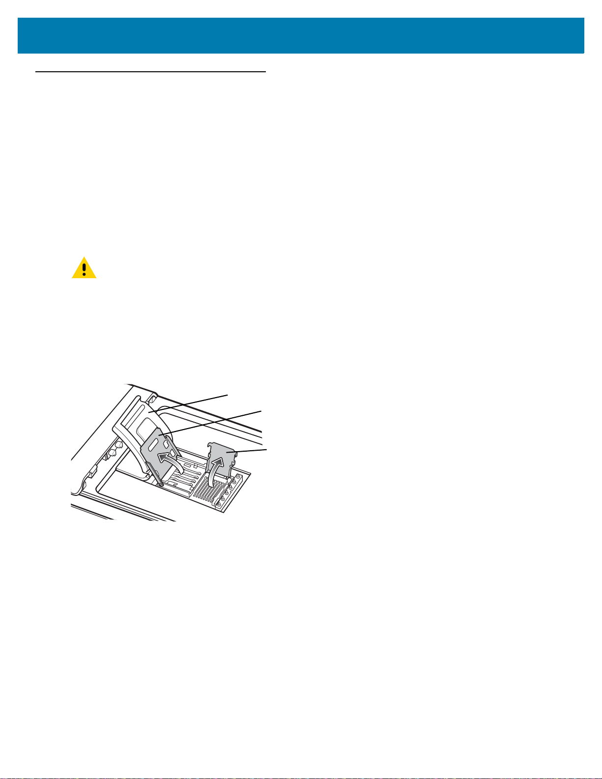
To install the microSD card:
1. Remove the handstrap.
2. Lift rubber access door.
3. Slide the SIM card holder door up to unlock.
4. Lift SIM card holder door.
Getting Started
Figure 2 Lift SIM Slot Holder Door
5. Lift microSD card holder door.
6. Insert the microSD card into card holder door ensuring that the card slides into the holding tabs on each side of
the door.
12
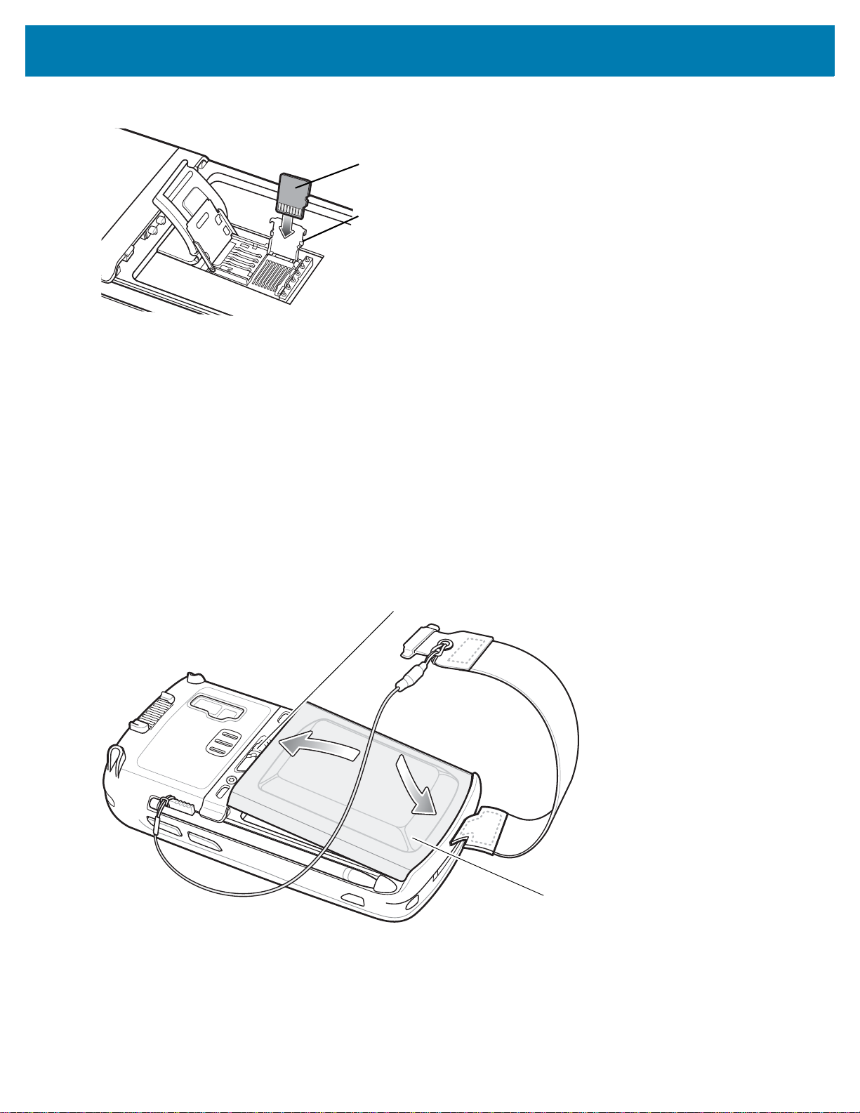
Getting Started
microSD card
Holding tab
1
2
Battery
Battery Release Latch
Figure 3 Insert microSD Card in Holder
7. Close the card holder door and push down until it is securely into place.
8. Close SIM card holder door and slide down until it locks into place.
9. Close rubber access door.
Installing the Battery
To install the battery.
1. Insert the battery, bottom first, into the battery compartment in the back of the MC55X.
2. Press the battery down into the battery compartment until the battery release latch snaps (2-clicks) into place.
The MC55X turns on if the battery is properly charged.
3. Replace the handstrap.
Figure 4 Inserting the Battery
13
Getting Started
Charging the Battery
CAUTION: Follow the guidelines for battery safety described in Battery Safety Guidelines on page 65.
Charging the Main Battery
Before using the MC55X for the first time, charge the main battery until the amber Charging/Battery Status light
emitting diode (LED) remains lit (see Table 3 on page 14 for charge status indications). To charge the MC55X, use
a cable or a cradle with the appropriate power supply. For information about the accessories available for the
MC55X, see Accessories.
The MC55X is equipped with a backup battery which automatically charges from the fully-charged main battery.
When using the MC55X for the first time, the backup battery requires approximately 40 hours to fully charge. This
is also true any time the backup battery is discharged, which occurs when the main battery is removed for several
hours. The backup battery retains random access memory (RAM) data in memory for at least 15 minutes (at room
temperature) when the MC55X’s main battery is removed. When the MC55X reaches a very low battery state, the
combination of main battery and backup battery retains RAM data in memory for at least 36 hours.
For cable and cradle setup and charging procedures see Accessories.
• USB Charging Cable
• Charge Only Cable
• Single Slot USB Cradle
• Four Slot Charge Only Cradle
• Four Slot Ethernet Cradle.
To charge the main battery:
1. Connect the charging accessory to the appropriate power source.
2. Insert the MC55X into a cradle or attach to a cable. The MC55X begins charging. The Charging/Battery Status
LED blinks amber while charging, then turns solid amber when fully charged. See Table 3 for charging
indications.
The 3600 mAh battery charges in less than six hours.
Table 3 LED Charge Indicators
Charging/Battery
Status LED
Off MC55X is not charging.
Slow Blinking Amber
(1 blink every 2 seconds)
Solid Amber Charging complete.
MC55X is not inserted correctly in the cradle or connected to a power source.
Charger/cradle is not powered.
MC55X is charging.
Note: When the battery is initially inserted in the MC55X, the amber LED flashes once
if the battery power is low or the battery is not fully inserted.
Indication
Fast Blinking Amber
(2 blinks/second)
Charging error, e.g.:
• Temperature is too low or too high.
• Charging has gone on too long without completion (typically eight hours).
14
Getting Started
Charging Spare Batteries
See Accessories for information on using accessories to change spare batteries.
Charging Temperature
Charge batteries in temperatures from 0 °C to 40 °C (32 °F to 104 °F). Note that charging is intelligently controlled
by the MC55X.
To accomplish this, for small periods of time, the MC55X or accessory alternately enables and disables battery
charging to keep the battery at acceptable temperatures. The MC55X or accessory indicates when charging is
disabled due to abnormal temperatures via its LED. See Table 3.
Powering On the MC55X
NOTE: If during installation of the battery, the battery has significant charge the MC55X turns on.
Press the Power button to turn on the MC55X. The splash screen displays for about a minute as the MC55X
initializes its flash file system, then the calibration window appears.
Calibrating the Screen
NOTE: The Calibration screen can be accessed by pressing Blue key then Backspace key.
To calibrate the screen so the cursor on the touch screen aligns with the tip of the stylus:
1. Remove the stylus from its holder on the side of the MC55X.
2. Carefully press and briefly hold the tip of stylus on the center of each target that appears on the screen.
3. Repeat as the target moves around the screen, then tap the screen to continue.
Replacing the Battery
To replace the battery:
CAUTION: The MC55X backup battery retains data for up to 15 minutes. Replace the battery within 15 minutes
to ensure that application states are maintained and that data is not lost.
1. If the MC55X is in a cradle, remove it before performing a Safe Battery Swap.
2. If the MC55X is in suspend mode, press the red Power button to wake the device.
3. Press the red Power button. The PowerKey Action screen appears.
4. Tap Safe Battery Swap. The Data Capture LED lights red.
5. When the LED turns off, remove the handstrap.
6. Slide the battery latch to the right. The battery ejects slightly.
15

Getting Started
1
Battery Latch
Figure 5 Removing the Battery
2
7. Lift the battery from the MC55X.
8. Insert the replacement battery, bottom first, into the battery compartment in the back of the MC55X.
9. Press the battery down until the battery release latch snaps (2-clicks) into place.
10. Replace the handstrap.
Resetting the MC55X
There are three reset functions; warm boot, cold boot, and clean boot. A warm boot restarts the MC55X by closing
all running programs. A cold boot also restarts the MC55X, and also initializes some drivers. Data saved in flash
memory or a memory card is not lost.
If the MC55X is not functioning properly, perform a warm boot first. If the MC55X still does not respond, perform a
cold boot.
Performing a Warm Boot
Hold down the red Power button for approximately five seconds. As soon as the MC55X starts to boot release the
Power button.
Performing a Cold Boot
To perform a cold boot:
• On a numeric keypad, simultaneously press the red Power button and the and keys.
• On an alphanumeric keypad, simultaneously press the red Power button and the and keys.
Performing a Clean Boot
CAUTION: A clean boot should only be performed by an authorized system administrator. You must connect
the MC55X to AC power during a clean boot.
Removing AC power from the MC55X during a clean boot may render the MC55X inoperable.
16
A clean boot resets the MC55X to the factory default settings. All data in the Application folder is retained. You
must download the Clean Boot Package file from the Support Central web site, http://www.zebra.com/support and
install on the MC55X.
To perform a clean boot:
1. Download the Clean Boot Package from the Support Central web site. Follow the instructions included in the
package for installing the package onto the MC55X.
2. Perform a warm boot.
3. Immediately, as soon as the device starts to boot and before the splash screen is visible, press and hold the
left scan button.
4. Insert the MC55X into a powered cradle.
5. The MC55X updates and then resets.
6. Calibrate the screen.
Waking the MC55X
The wake-up conditions define what actions wake up the MC55X after it has gone into suspend mode. The MC55X
can go into suspend mode by either pressing the Power button or automatically by Control Panel time-out settings.
To set the wake up conditions tap > Settings > System > Power > Wakeup.
Getting Started
Table 4 Wake-up Default Settings
Condition for Wake-up Power Button Automatic Time-out
MC55X is connected to a USB cable. Yes Yes
MC55X is connected toto a USB Host Device No No
A key is pressed. No Yes
The screen is touched. No No
Right Trigger is pressed. Yes Yes
Left Trigger is pressed. Yes Yes
17

Accessories
Introduction
This chapter provides set up information for the MC55X various accessories listed in Table 5.
Table 5 MC55X Accessories
Accessory Part Number Description
Cradles
Single Slot USB Cradle CRD5500-1000UR Charges the MC55X main battery and a spare battery.
Synchronizes the MC55X with a host computer through
a USB connection.
Single Slot
Ethernet/Modem/USB
Cradle
Four Slot Charge Only
Cradle
Four Slot Ethernet Cradle CRD5501-4000ER Charges up to four MC55X devices and connects the
Vehicle Cradle VCD5500-1001R Installs in a vehicle and charges the MC55X main
Vehicle Holder VCH5500-1000R Provides an alternative mounting solution for the
Chargers
Four Slot Spare Battery
Charger
Power Supply PWR-BGA5V16W0WW Provides power to the MC55X using the USB Charging
Power Supply PWR-BGA12V50W0WW Provides power to the Single Slot USB cradle and Four
CRD5500-1000XR Charges the MC55X main battery and a spare battery.
Synchronizes the MC55X with a host computer through
an Ethernet, Modem or USB connection.
CRD5501-4000CR Charges up to four MC55X devices.
MC55X with an Ethernet network. CRD5501-4000ER
provides up to a maximum of 1 Gbps.
battery.
MC55X in a vehicle. Requires the Auto Charge cable
for charging the MC55X battery.
SAC5500-4000CR Charges up to four MC55X battery packs.
Cable or Charge Only Cable.
Slot Spare Battery Charger.
18

Accessories
Table 5 MC55X Accessories (Continued)
Accessory Part Number Description
Power Supply PWR-BGA12V108W0WW Provides power to the Four Slot Charge Only cradle or
Four Slot Ethernet cradles.
USB Charging Cable 25-108022-03R Provides power to the MC55X and USB
communication with a host computer.
Charge Only Cable 25-112560-02R Connects to a power supply to provide power to the
MC55X.
Auto Charge Cable VCA5500-01R Charges the MC55X using a vehicle’s cigarette lighter.
DC Cable CBL-DC-388A1-01 Provides power from the power supply to the single slot
cradles.
DC Cable CBL-DC-382A1-01 Provides power from the power supply to the Four Slot
cradles.
Miscellaneous
Spare 3600 mAh
lithium-ion battery
DEX Cable 25-127558-01R For use with electronic data exchange For example,
USB Client
Communication Cable
Printer Cable 25-136283-01R Provides connection to a Monarch/Paxar Serial printer.
Trigger Handle TRG5500-101R Adds a gun-style handle with a scanning trigger for
Trigger Handle Hand
Strap
Belt Mounted Rigid
Holster
Fabric Holster SG-MC5521110-01R Soft holder for added protection.
Stylus KT-119150-03R
Spring Loaded Stylus STYLUS-00001-03R
BTRY-MC55EAB02
BTRY-MC55EAB02-10
BTRY-MC55EAB02-50
25-68596-01R Provides USB communication between the Single Slot
21-138874-01R Handstrap for the Trigger handle.
SG-MC5511110-01R Clips onto belt to hold the MC55X when not in use.
KT-119150-50R
STYLUS-00001-10R
Replacement 3600 mAh battery.
(10-pack)
(50-pack)
vending machines.
USB Cradle and a host computer.
comfortable and productive data capture.
Replacement stylus (3-pack).
Replacement stylus (50-pack).
Optional spring loaded stylus (3-pack).
Optional spring loaded stylus (10-pack).
Stylus with Tether Stylus-00003-03R
Stylus-00003-50R
Spare Tether KT-122621-03R
KT-122621-50R
Handstrap SG-MC5523341-03R Replacement handstrap with pin
Wall Mounting Kit KT-136648-01R Use for wall mounting the four slot cradles.
Screen Protector KT-137521-03R Package of 3 screen protectors.
Spare stylus with tether (3-pack).
(50-pack).
Replacement tether (3-pack).
(50-pack).
19

• Magnetic Stripe Reader - Snaps on to the MC55X and adds magstripe read capabilities.
Power Supply
USB Port
Power Port
AC Line Cord
Single Slot USB Cradle
This section describes how to set up and use a Single Slot USB cradle with the MC55X. For USB communication
setup procedures see Synchronization.
The Single Slot USB cradle:
• Provides 5.4 VDC power for operating the MC55X.
• Synchronizes information between the MC55X and a host computer. See Synchronization for information
on setting up a partnership between the MC55X and a host computer.
• Charges the MC55X’s battery.
• Charges a spare battery.
Setup
Figure 6 Single Slot USB Cradle Power and USB Connections
Accessories
Charging the MC55X Battery
Connect the cradle to power. Insert the MC55X into the MC55X slot to begin charging.
20

Figure 7 MC55X Battery Charging
Charge Status LED
Spare Battery
Spare Battery
Charging LED
Accessories
Charging the Spare Battery
Figure 8 Spare Battery Charging
Battery Charging Indicators
The Single Slot USB cradle charges the MC55X’s main battery and a spare battery simultaneously.
21
Accessories
The MC55X’s Charging/Battery Status LED indicates the status of the battery charging in the MC55X. See Table 3
on page 14 for charging status indications.
The spare battery charging LED on the cradle indicates the status of the spare battery charging in the cradle. See
Table 6 for charging status indications.
The 3600 mAh battery fully charges in approximately six hours.
Charging Temperature
Charge batteries in temperatures from 0°C to 40°C (32°F to 104°F). Charging is intelligently controlled by the
MC55X.
To accomplish this, for small periods of time, the MC55X or accessory alternately enables and disables battery
charging to keep the battery at acceptable temperatures. The MC55X or accessory indicates when charging is
disabled due to abnormal temperatures via its LED. See Table 3 on page 14 and Table 6.
Table 6 Spare Battery LED Charging Indicators
Spare Battery LED
(on cradle)
Slow Blinking Amber Spare battery is charging.
Solid Amber Spare battery is fully charged.
Fast Blinking Amber Charging error.
Off Not charging.
Indication
22

Accessories
Power Supply
Ethernet Port Power Port
AC Line Cord
USB Port Phone Port
Ethernet Hub
Single Slot Ethernet/Modem/USB Cradle
This section describes how to set up and use a Single Slot Ethernet/Modem/USB cradle with the MC55X. For USB
communication setup procedures see Synchronization.
The Single Slot Ethernet/Modem/USB cradle:
• Provides 5.4 VDC power for operating the MC55X.
• Connects the MC55X to a host computer using USB, or an Ethernet network.
• Charges the MC55X’s battery.
• Charges a spare battery.
Setup
Figure 9 Cradle Setup
23
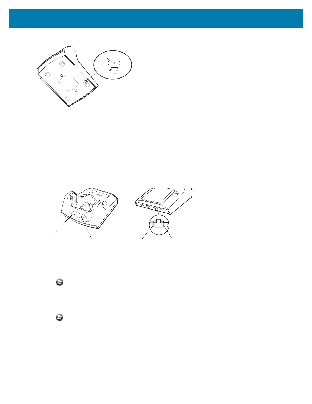
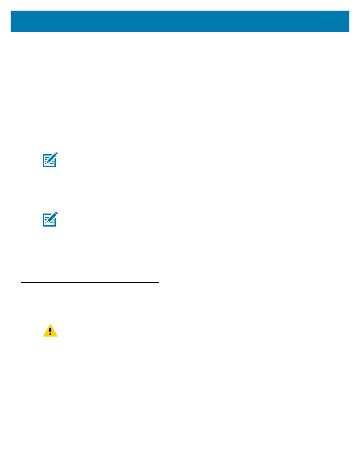
Figure 10 Connection Switch
Modem USB Ethernet
Ethernet/Modem LED
Spare Battery
Charging LED
Speed LED
Link LED
Indicators
• Spare Battery Charging LED - Indicates the charging status of the spare battery.
• Ethernet/Modem LED - Blinks whenever Ethernet connectivity is established.
• Speed LED - Lights green indicating that the transfer rate is 100 Mbps. When it is not lit, indicates that the
transfer rate is 10Mbps.
• Link LED - Blinks yellow to indicate activity, or stays lit to indicate that a link is established. When it is not
lit, indicates there is no link.
Accessories
Figure 11 Cradle Indicators
MC55X Software Setup
Ethernet Setup
1. Tap > Settings > Connections tab > Wi-Fi icon.
2. Select Work from the drop-down menu.
3. Select USB/Ethernet Series Adapter from the list box.
4. Tap Ok.
5. Tap > Settings > Connections tab > Connections icon.
6. Tap Advanced tab.
7. Tap Select Networks button.
8. Select My Work Network from both drop-down menus.
9. Tap Ok.
10. Tap the Tasks tab.
11. Select Edit my proxy server.
24

Accessories
12. Enable both checkboxes.
13. Tap Advanced... button.
14. Tap HTTP type.
15. In the Server text box, enter the proxy server name.
16. In the Port text box, enter the port number.
17. In the User name text box, enter the user name for the proxy server.
18. In the Password text box, enter the password for the proxy server.
19. Tap ok three times.
20. Perform a warm boot.
25
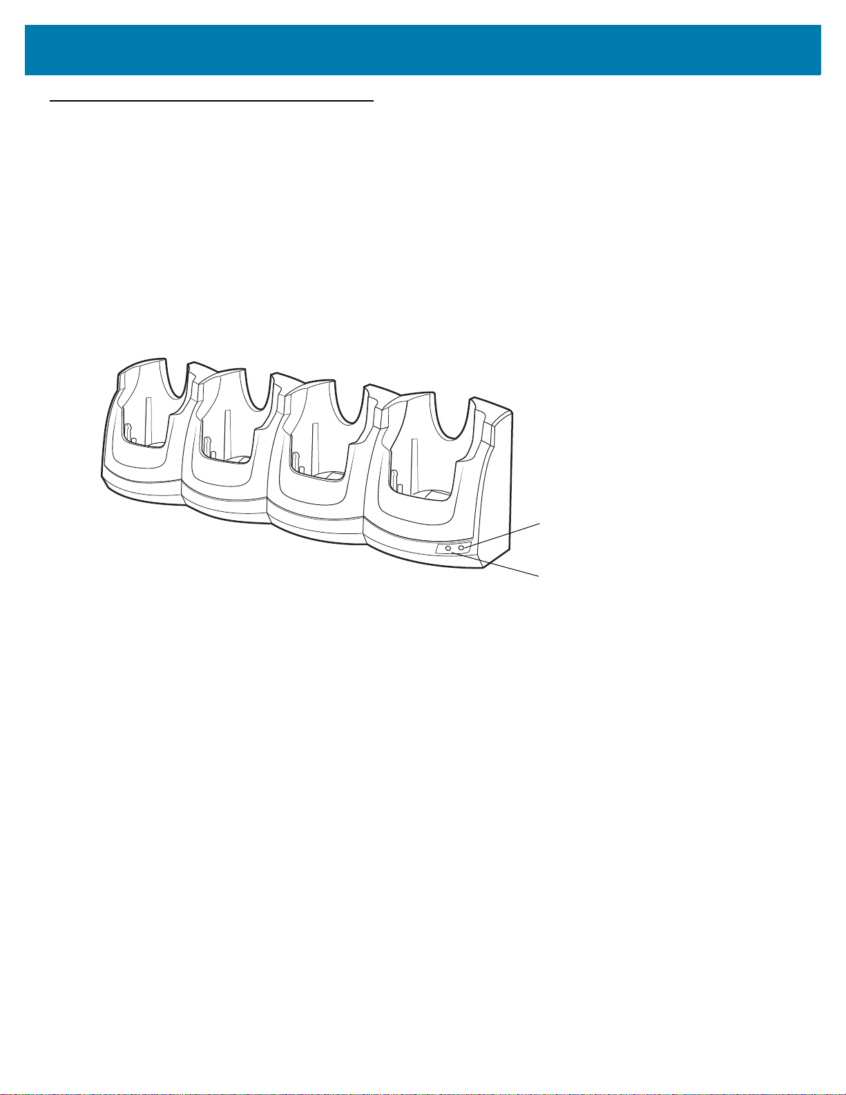
Four Slot Ethernet Cradle
Green 100 LED
Green 1000 LED
This section describes how to set up and use a Four Slot Ethernet cradle with the MC55X.
The Four Slot Ethernet cradle:
• Provides 5.4 VDC power for operating the MC55X.
• Connects the MC55X (up to four) to an Ethernet network.
• Simultaneously charges up to four MC55Xs.
The user cannot ActiveSync using the Four Slot Ethernet cradle. To ActiveSync with a host computer, use the
Single Slot USB/Serial cradle, USB Charging cable or Serial Charging cable.
Figure 12 Four Slot Ethernet Cradle
Accessories
Setup
Connect the Four Slot Ethernet cradle to a power source and to an Ethernet switch, router, or hub, or a port on the
host device.
26
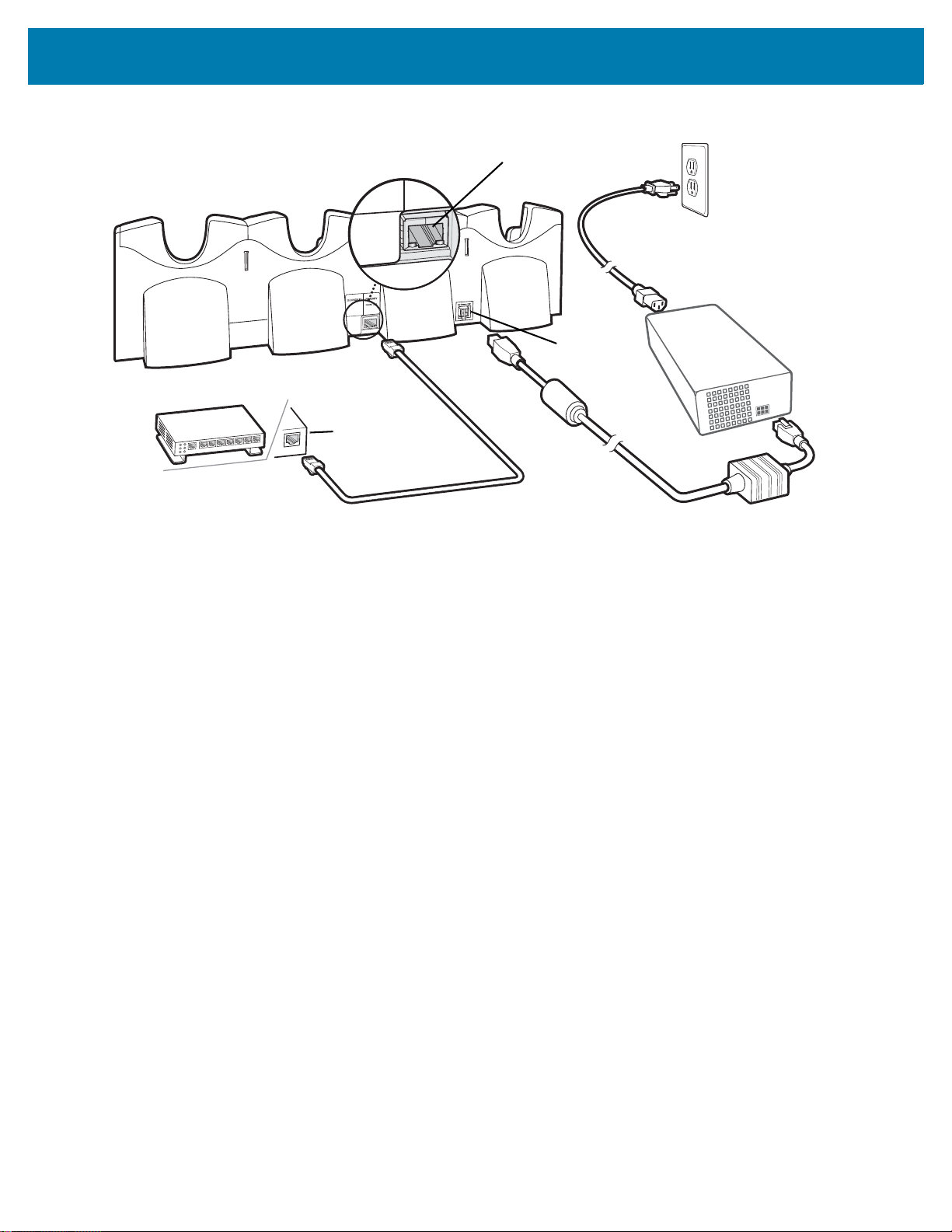
Accessories
Power Port
Ethernet Switch,
Router, or Hub
Connection
Primary Port
Figure 13 Four Slot Ethernet Cradle Connection
Daisychaining Ethernet Cradles
Daisychain up to four Four Slot Ethernet cradles to connect several cradles to an Ethernet network. Use either a
straight or crossover cable. Daisy-chaining should not be attempted when the main Ethernet connection to the first
cradle is 10 Mbps as throughput issues will almost certainly result.
To daisychain more than Four Slot Ethernet cradles:
1. Connect power to each Four Slot Ethernet cradle.
2. Connect an Ethernet cable to the Primary Port of the first cradle and to the Ethernet switch. See Figure 13.
3. On the first Four Slot Ethernet cradle, lift or remove the label flap and connect a second Ethernet cable to the
Secondary Port. See Figure 14.
4. Connect the other end of the Ethernet cable to the Primary Port of the second Four Slot Ethernet cradle.
5. Connect additional cradles as described in step 3 and 4.
27
 Loading...