

Page 1
DS8108
MN-002926-01
Digital Scanner
Product Reference Guide
Page 2

Page 3

DS8108 DIGITAL SCANNER
PRODUCT REFERENCE GUIDE
MN-002926-01
Revision A
March 2017
Page 4

ii DS8108 Digital Scanner Product Reference Guide
No part of this publication may be reproduced or used in any form, or by any electrical or mechanical means,
without permission in writing from Zebra. This includes electronic or mechanical means, such as photo copying,
recording, or information storage and retrieval systems. The material in this manual is subject to change
without notice.
The software is provided strictly on an “as is” basis. All software, including firmware, furnished to the user is on
a licensed basis. Zebra grants to the user a non-transferable and non-exclusive license to use each software
or firmware program delivered hereunder (licensed program) . Except as n oted below, such license may not be
assigned, sublicensed, or otherwise tran sfe rr e d by th e user without prior written consent of Zebra. No right to
copy a licensed program in whole or in part is granted, except as permitted under copyright law. The user shall
not modify , merge, or incorporate any for m or portion of a licensed program with other pro gram material, create
a derivative work from a licensed program , or us e a li censed program in a network without written permission
from Zebra. The user agrees to maintain Zebra’s copyright notice on the licensed programs delivered
hereunder , and to include the same on any au thorized copies it m akes, in whole or in part. The user agrees not
to decompile, disassemble, decode, or reverse engineer any licensed program delivered to the user or any
portion thereof.
Zebra reserves the right to make changes to any product to improve reliability, function, or design.
Zebra does not assume any product liability arising out of, or in connection with, the application or use of any
product, circuit, or application described herein. No license is granted, either expressly or by implication,
estoppel, or otherwise under any patent right or patent, covering or relating to any combination, system,
apparatus, machine, material, method, or process in which Zebra products might be used. An implied license
exists only for equipment, circuits, and subsystems contained in Zebra products.
Warranty
For the complete hardware product warranty statement, go to: http://www.zebra.com/warranty.
Page 5

Revision History
Changes to the original guide are listed below:
Change Date Description
-01 Rev A 03/2017 Initial Release
iii
Page 6

iv DS8108 Digital Scanner Product Reference Guide
Page 7

TABLE OF CONTENTS
Warranty ............................................................................................................................................ ii
Revision History................................................................................................................................. iii
About This Guide
Introduction...................................................................................................................................... xix
Configurations.................................................................................................................................. xix
Related Product Line Configurations/Accessories........................................................................... xx
Cables........................................................................................................................................ xx
Chapter Descriptions ....................................................................................................................... xx
Notational Conventions.................................................................................................................... xxi
Related Documents and Software.................................................................................................. xxii
Service Information........................................................................................................................ xxiii
Chapter 1: Getting Started
Introduction .................................................................................................................................... 1-1
Interfaces ....................................................................................................................................... 1-2
Unpacking ...................................................................................................................................... 1-2
Setting Up the Digital Scanner ....................................................................................................... 1-3
Installing the Interface Cable .................................................................................................... 1-3
Removing the Interface Cable .................................................................................................. 1-4
Connecting Power (if required) ................................................................................................ 1-4
Configuring the Digital Scanner ............................................................................................... 1-4
Chapter 2: Data Capture
Introduction .................................................................................................................................... 2-1
Beeper and LED Indicators ............................................................................................................ 2-2
Scanning ........................................................................................................................................ 2-4
Scanning in Presentation (Hands-free) Mode .......................................................................... 2-4
Scanning in Hand-held Mode ................................................................................................... 2-7
Aiming ...................................................................................................................................... 2-7
Decode Ranges ............................................................................................................................. 2-9
Page 8

vi DS8108 Digital Scanner Product Reference Guide
DS8108-SR/DL Configurations ................................................................................................ 2-9
DS8108-HC Configurations .................................................................................................... 2-10
Assembling the Document Capture Stand ................................................................................... 2-11
Assembly ................................................................................................................................ 2-12
Chapter 3: Maintenance, Troubleshooting, & Technical Specifications
Introduction .................................................................................................................................... 3-1
Maintenance .................................................................................................................................. 3-1
Known Harmful Ingredients ...................................................................................................... 3-1
Approved Cleaners for Standard DS8108 Digital Scanners .................................................... 3-2
Approved Disinfectant Cleaners for Healthcare Configurations
of the DS8108 Digital Scanners ......................................................................................... 3-2
Cleaning the Digital Scanner .................................................................................................... 3-3
Troubleshooting ............................................................................................................................. 3-4
Dump Scanner Parameters ...................................................................................................... 3-6
Send Versions .......................................................................................................................... 3-7
Technical Specifications ................................................................................................................ 3-8
Digital Scanner Signal Descriptions ............................................................................................. 3-11
Chapter 4: USB Interface
Introduction .................................................................................................................................... 4-1
Setting Parameters ........................................................................................................................ 4-1
Scanning Sequence Examples ................................................................................................ 4-1
Errors While Scanning ............................................................................................................. 4-2
Connecting a USB Interface .......................................................................................................... 4-2
USB Parameter Defaults ................................................................................................................ 4-4
USB Host Parameters .................................................................................................................... 4-5
USB Device Type ..................................................................................................................... 4-5
Symbol Native API (SNAPI) Status Handshaking .................................................................... 4-7
USB Keystroke Delay ............................................................................................................... 4-7
USB Caps Lock Override ......................................................................................................... 4-8
Bar Codes with Unknown Characters ...................................................................................... 4-8
USB Convert Unknown to Code 39 .......................................................................................... 4-9
USB Fast HID ........................................................................................................................... 4-9
USB Polling Interval ............................................................................................................... 4-10
Keypad Emulation .................................................................................................................. 4-12
Quick Keypad Emulation ........................................................................................................ 4-12
Keypad Emulation with Leading Zero .................................................................................... 4-13
USB Keyboard FN1 Substitution ............................................................................................ 4-13
Function Key Mapping ........................................................................................................... 4-14
Simulated Caps Lock ............................................................................................................. 4-14
Convert Case ......................................................................................................................... 4-15
USB Static CDC ..................................................................................................................... 4-15
TGCS (IBM) USB Beep Directive ........................................................................................... 4-16
TGCS (IBM) USB Bar Code Configuration Directive ............................................................. 4-16
TGCS (IBM) USB Specification Version ................................................................................ 4-17
ASCII Character Sets ................................................................................................................... 4-17
Page 9

Table of Contents vii
Chapter 5: SSI Interface
Introduction .................................................................................................................................... 5-1
Communication .............................................................................................................................. 5-1
SSI Commands ........................................................................................................................ 5-2
SSI Transactions ............................................................................................................................ 5-3
General Data Transactions ...................................................................................................... 5-3
Decoded Data Transmission .................................................................................................... 5-4
Communication Summary .............................................................................................................. 5-5
RTS/CTS Lines ........................................................................................................................ 5-5
ACK/NAK Option ...................................................................................................................... 5-5
Number of Data Bits ................................................................................................................. 5-5
Serial Response Timeout ......................................................................................................... 5-6
Retries ...................................................................................................................................... 5-6
Baud Rate, Stop Bits, Parity, Response Timeout, ACK/NAK Handshaking ............................. 5-6
Errors ....................................................................................................................................... 5-6
SSI Communication Notes ....................................................................................................... 5-6
Using Time Delay to Low Power Mode with SSI ............................................................................ 5-7
Encapsulation of RSM Commands/Responses over SSI .............................................................. 5-8
Command Structure ................................................................................................................. 5-8
Response Structure ................................................................................................................. 5-8
Example Transaction ............................................................................................................... 5-9
Setting Parameters ...................................................................................................................... 5-10
Scanning Sequence Examples .............................................................................................. 5-10
Errors While Scanning ........................................................................................................... 5-10
Simple Serial Interface Parameter Defaults ................................................................................. 5-11
SSI Host Parameters ................................................................................................................... 5-12
Select SSI Host ...................................................................................................................... 5-12
Baud Rate .............................................................................................................................. 5-12
Parity ...................................................................................................................................... 5-14
Check Parity ........................................................................................................................... 5-15
Stop Bits ................................................................................................................................. 5-15
Software Handshaking ........................................................................................................... 5-16
Host RTS Line State .............................................................................................................. 5-17
Decode Data Packet Format .................................................................................................. 5-17
Host Serial Response Timeout .............................................................................................. 5-18
Host Character Timeout ......................................................................................................... 5-19
Multipacket Option ................................................................................................................. 5-20
Interpacket Delay ................................................................................................................... 5-21
Event Reporting ........................................................................................................................... 5-22
Decode Event ......................................................................................................................... 5-22
Boot Up Event ........................................................................................................................ 5-23
Parameter Event .................................................................................................................... 5-23
Chapter 6: RS-232 Interface
Introduction .................................................................................................................................... 6-1
Setting Parameters ........................................................................................................................ 6-1
Scanning Sequence Examples ................................................................................................ 6-2
Errors While Scanning ............................................................................................................. 6-2
Connecting an RS-232 Interface .................................................................................................... 6-2
Page 10

viii DS8108 Digital Scanner Product Reference Guide
RS-232 Parameter Defaults ........................................................................................................... 6-3
RS-232 Host Parameters ............................................................................................................... 6-4
RS-232 Host Types .................................................................................................................. 6-6
Baud Rate ................................................................................................................................ 6-8
Parity ........................................................................................................................................ 6-9
Stop Bits ................................................................................................................................. 6-10
Data Bits ................................................................................................................................. 6-10
Check Receive Errors ............................................................................................................ 6-11
Hardware Handshaking .......................................................................................................... 6-11
Software Handshaking ........................................................................................................... 6-13
Host Serial Response Timeout .............................................................................................. 6-15
RTS Line State ....................................................................................................................... 6-16
Beep on <BEL> ...................................................................................................................... 6-16
Intercharacter Delay ............................................................................................................... 6-17
Nixdorf Beep/LED Options ..................................................................................................... 6-18
Bar Codes with Unknown Characters .................................................................................... 6-18
ASCII Character Sets ................................................................................................................... 6-18
Chapter 7: IBM 468X / 469X Interface
Introduction .................................................................................................................................... 7-1
Setting Parameters ........................................................................................................................ 7-1
Scanning Sequence Examples ................................................................................................ 7-1
Errors While Scanning ............................................................................................................. 7-2
Connecting an IBM 468X/469X Host ............................................................................................. 7-2
IBM Parameter Defaults ................................................................................................................. 7-3
IBM Host Parameters ..................................................................................................................... 7-4
Port Address ............................................................................................................................ 7-4
Convert Unknown to Code 39 .................................................................................................. 7-5
RS-485 Beep Directive ............................................................................................................. 7-5
RS-485 Bar Code Configuration Directive ............................................................................... 7-6
IBM-485 Specification Version ................................................................................................. 7-6
Chapter 8: Keyboard Wedge Interface
Introduction .................................................................................................................................... 8-1
Setting Parameters ........................................................................................................................ 8-1
Scanning Sequence Examples ................................................................................................ 8-1
Errors While Scanning ............................................................................................................. 8-2
Connecting a Keyboard Wedge Interface ...................................................................................... 8-2
Keyboard Wedge Parameter Defaults ........................................................................................... 8-3
Keyboard Wedge Host Parameters ................................ ........... ........... .......... ............................... 8-4
Keyboard Wedge Host Types .................................................................................................. 8-4
Bar Codes with Unknown Characters ...................................................................................... 8-4
Keystroke Delay ....................................................................................................................... 8-5
Intra-keystroke Delay ............................................................................................................... 8-5
Alternate Numeric Keypad Emulation ...................................................................................... 8-6
Quick Keypad Emulation .......................................................................................................... 8-6
Simulated Caps Lock ............................................................................................................... 8-7
Caps Lock Override ................................................................................................................. 8-7
Page 11

Table of Contents ix
Convert Case ........................................................................................................................... 8-8
Function Key Mapping ............................................................................................................. 8-8
FN1 Substitution ....................................................................................................................... 8-9
Send Make and Break .............................................................................................................. 8-9
Keyboard Map .............................................................................................................................. 8-10
ASCII Character Sets ................................................................................................................... 8-10
Chapter 9: User Preferences & Miscellaneous Options
Introduction .................................................................................................................................... 9-1
Setting Parameters ........................................................................................................................ 9-1
Scanning Sequence Examples ................................................................................................ 9-2
Errors While Scanning ............................................................................................................. 9-2
User Preferences/Miscellaneous Options Parameter Defaults ...................................................... 9-2
User Preferences ........................................................................................................................... 9-5
Default Parameters .................................................................................................................. 9-5
Parameter Bar Code Scanning ................................................................................................ 9-6
Beep After Good Decode ......................................................................................................... 9-6
Beeper Volume ........................................................................................................................ 9-7
Beeper Tone ............................................................................................................................ 9-8
Beeper Duration ....................................................................................................................... 9-9
Suppress Power Up Beeps ...................................................................................................... 9-9
Direct Decode Indicator .......................................................................................................... 9-10
Decode Pager Motor .............................................................................................................. 9-11
Decode Pager Motor Duration ............................................................................................... 9-12
Night Mode (DS8108-HC Only) .............................................................................................. 9-13
Low Power Mode ................................................................................................................... 9-15
Hand-held Trigger Mode ........................................................................................................ 9-18
Hands-free Mode ................................................................................................................... 9-19
Hand-held Decode Aiming Pattern ......................................................................................... 9-20
Presentation (Hands-free) Decode Aiming Pattern ................................................................ 9-21
Picklist Mode .......................................................................................................................... 9-22
Continuous Bar Code Read ................................................................................................... 9-23
Unique Bar Code Reporting ................................................................................................... 9-23
Decode Session Timeout ....................................................................................................... 9-24
Hands-free Decode Session Timeout .................................................................................... 9-24
Timeout Between Decodes, Same Symbol ............................................................................ 9-25
Timeout Between Decodes, Different Symbols ...................................................................... 9-25
Triggered Timeout, Same Symbol ......................................................................................... 9-26
Mobile Phone/Display Mode .................................................................................................. 9-27
PDF Prioritization ................................................................................................................... 9-28
PDF Prioritization Timeout ..................................................................................................... 9-28
Presentation (Hands-free) Mode Field of View ...................................................................... 9-29
Decoding Illumination ............................................................................................................. 9-29
Illumination Brightness ........................................................................................................... 9-30
Motion Tolerance (Hand-held Trigger Modes Only) ............................................................... 9-31
Miscellaneous Scanner Parameters ............................................................................................ 9-31
Enter Key ............................................................................................................................... 9-31
Tab Key .................................................................................................................................. 9-31
Transmit Code ID Character .................................................................................................. 9-32
Page 12

x DS8108 Digital Scanner Product Reference Guide
Prefix/Suffix Values ................................................................................................................ 9-33
Scan Data Transmission Format ............................................................................................ 9-34
FN1 Substitution Values ......................................................................................................... 9-36
Transmit “No Read” Message ................................................................................................ 9-37
Unsolicited Heartbeat Interval ................................................................................................ 9-38
Chapter 10: Image Capture Preferences
Introduction .................................................................................................................................. 10-1
Setting Parameters ...................................................................................................................... 10-1
Scanning Sequence Examples .............................................................................................. 10-2
Errors While Scanning ........................................................................................................... 10-2
Image Capture Preferences Parameter Defaults ......................................................................... 10-2
Image Capture Preferences ......................................................................................................... 10-4
Operational Modes ................................................................................................................. 10-4
Image Capture Illumination .................................................................................................... 10-5
Image Capture Autoexposure ................................................................................................ 10-5
Fixed Exposure ...................................................................................................................... 10-6
Fixed Gain .............................................................................................................................. 10-6
Gain/Exposure Priority for Snapshot Mode ............................................................................ 10-7
Snapshot Mode Timeout ........................................................................................................ 10-8
Snapshot Aiming Pattern ....................................................................................................... 10-9
Silence Operational Mode Changes ...................................................................................... 10-9
Image Cropping .................................................................................................................... 10-10
Crop to Pixel Addresses ....................................................................................................... 10-10
Image Size (Number of Pixels) ............................................................................................ 10-12
Image Brightness (Target White) ......................................................................................... 10-13
JPEG Image Options ........................................................................................................... 10-13
JPEG Quality Value ............................................................................................................. 10-14
JPEG Size Value .................................................................................................................. 10-14
Image Enhancement ............................................................................................................ 10-15
Image File Format Selector .................................................................................................. 10-16
Image Rotation ..................................................................................................................... 10-17
Bits Per Pixel ........................................................................................................................ 10-18
Signature Capture ................................................................................................................ 10-19
Signature Capture File Format Selector ............................................................................... 10-20
Signature Capture Bits Per Pixel .......................................................................................... 10-21
Signature Capture Width ...................................................................................................... 10-22
Signature Capture Height ..................................................................................................... 10-22
Signature Capture JPEG Quality ......................................................................................... 10-22
Video View Finder ................................................................................................................ 10-23
Video View Finder Image Size ............................................................................................. 10-23
Chapter 11: Symbologies
Introduction .................................................................................................................................. 11-1
Setting Parameters ...................................................................................................................... 11-1
Scanning Sequence Examples .............................................................................................. 11-2
Errors While Scanning ........................................................................................................... 11-2
Symbology Parameter Defaults ................................................................................................... 11-2
Page 13

Table of Contents xi
Enable/Disable All Code Types ................................................................................................... 11-8
UPC/EAN/JAN ............................................................................................................................. 11-9
UPC-A .................................................................................................................................... 11-9
UPC-E .................................................................................................................................... 11-9
UPC-E1 ................................................................................................................................ 11-10
EAN-8/JAN-8 ........................................................................................................................ 11-10
EAN-13/JAN-13 .................................................................................................................... 11-11
Bookland EAN ...................................................................................................................... 11-11
Bookland ISBN Format ........................................................................................................ 11-12
ISSN EAN ............................................................................................................................ 11-13
Decode UPC/EAN/JAN Supplementals ............................................................................... 11-14
User-Programmable Supplementals .................................................................................... 11-17
UPC/EAN/JAN Supplemental Redundancy ......................................................................... 11-17
UPC/EAN/JAN Supplemental AIM ID Format ...................................................................... 11-18
Transmit UPC-A Check Digit ................................................................................................ 11-19
Transmit UPC-E Check Digit ................................................................................................ 11-19
Transmit UPC-E1 Check Digit .............................................................................................. 11-20
UPC-A Preamble .................................................................................................................. 11-21
UPC-E Preamble .................................................................................................................. 11-22
UPC-E1 Preamble ................................................................................................................ 11-23
Convert UPC-E to UPC-A .................................................................................................... 11-24
Convert UPC-E1 to UPC-A .................................................................................................. 11-24
EAN/JAN Zero Extend ......................................................................................................... 11-25
UCC Coupon Extended Code .............................................................................................. 11-25
Coupon Report ..................................................................................................................... 11-26
UPC Reduced Quiet Zone ................................................................................................... 11-27
Code 128 ................................................................................................................................... 11-28
Set Lengths for Code 128 .................................................................................................... 11-28
GS1-128 (formerly UCC/EAN-128) ...................................................................................... 11-30
ISBT 128 .............................................................................................................................. 11-30
ISBT Concatenation ............................................................................................................. 11-31
Check ISBT Table ................................................................................................................ 11-32
ISBT Concatenation Redundancy ........................................................................................ 11-32
Code 128 <FNC4> ............................................................................................................... 11-33
Code 128 Security Level ...................................................................................................... 11-34
Code 128 Reduced Quiet Zone ........................................................................................... 11-36
Code 39 ..................................................................................................................................... 11-37
Trioptic Code 39 ................................................................................................................... 11-37
Convert Code 39 to Code 32 ............................................................................................... 11-38
Code 32 Prefix ..................................................................................................................... 11-38
Set Lengths for Code 39 ...................................................................................................... 11-39
Code 39 Check Digit Verification ......................................................................................... 11-40
Transmit Code 39 Check Digit ............................................................................................. 11-41
Code 39 Full ASCII Conversion ........................................................................................... 11-41
Code 39 Security Level ........................................................................................................ 11-42
Code 39 Reduced Quiet Zone ............................................................................................. 11-44
Code 93 ..................................................................................................................................... 11-45
Set Lengths for Code 93 ...................................................................................................... 11-45
Code 11 ..................................................................................................................................... 11-47
Set Lengths for Code 11 ...................................................................................................... 11-47
Page 14

xii DS8108 Digital Scanner Product Reference Guide
Code 11 Check Digit Verification ......................................................................................... 11-49
Transmit Code 11 Check Digits ........................................................................................... 11-50
Interleaved 2 of 5 (ITF) .............................................................................................................. 11-51
Set Lengths for Interleaved 2 of 5 ........................................................................................ 11-51
I 2 of 5 Check Digit Verification ............................................................................................ 11-53
Transmit I 2 of 5 Check Digit ................................................................................................ 11-54
Convert I 2 of 5 to EAN-13 ................................................................................................... 11-54
I 2 of 5 Security Level ........................................................................................................... 11-55
I 2 of 5 Reduced Quiet Zone ................................................................................................ 11-56
Discrete 2 of 5 (DTF) ................................................................................................................. 11-57
Set Lengths for Discrete 2 of 5 ............................................................................................. 11-57
Codabar (NW - 7) ....................................................................................................................... 11-59
Set Lengths for Codabar ...................................................................................................... 11-59
CLSI Editing ......................................................................................................................... 11-61
NOTIS Editing ...................................................................................................................... 11-61
Codabar Upper or Lower Case Start/Stop Characters ......................................................... 11-62
MSI ............................................................................................................................................. 11-63
Set Lengths for MSI ............................................................................................................. 11-63
MSI Check Digits .................................................................................................................. 11-65
Transmit MSI Check Digit(s) ................................................................................................ 11-65
MSI Check Digit Algorithm ................................................................................................... 11-66
MSI Reduced Quiet Zone ..................................................................................................... 11-66
Chinese 2 of 5 ............................................................................................................................ 11-67
Matrix 2 of 5 ............................................................................................................................... 11-68
Set Lengths for Matrix 2 of 5 ................................................................................................ 11-68
Matrix 2 of 5 Check Digit ...................................................................................................... 11-70
Transmit Matrix 2 of 5 Check Digit ....................................................................................... 11-70
Korean 3 of 5 ............................................................................................................................. 11-71
Inverse 1D .................................................................................................................................. 11-72
GS1 DataBar .............................................................................................................................. 11-73
GS1 DataBar Omnidirectional (formerly GS1 DataBar-14) .................................................. 11-73
GS1 DataBar Limited ........................................................................................................... 11-73
GS1 DataBar Expanded ....................................................................................................... 11-74
Convert GS1 DataBar to UPC/EAN/JAN ............................................................................. 11-74
GS1 DataBar Security Level ................................................................................................ 11-75
GS1 DataBar Limited Margin Check .................................................................................... 11-76
Symbology-Specific Security Features ...................................................................................... 11-77
Redundancy Level ............................................................................................................... 11-77
Security Level ....................................................................................................................... 11-79
1D Quiet Zone Level ............................................................................................................ 11-80
Intercharacter Gap Size ....................................................................................................... 11-81
Composite .................................................................................................................................. 11-82
Composite CC-C .................................................................................................................. 11-82
Composite CC-A/B ............................................................................................................... 11-82
Composite TLC-39 ............................................................................................................... 11-83
Composite Inverse ............................................................................................................... 11-83
UPC Composite Mode ......................................................................................................... 11-84
Composite Beep Mode ......................................................................................................... 11-85
GS1-128 Emulation Mode for UCC/EAN Composite Codes ................................................ 11-85
2D Symbologies ......................................................................................................................... 11-86
Page 15

Table of Contents xiii
PDF417 ................................................................................................................................ 11-86
MicroPDF417 ....................................................................................................................... 11-86
Code 128 Emulation ............................................................................................................. 11-87
Data Matrix ........................................................................................................................... 11-88
GS1 Data Matrix ................................................................................................................... 11-88
Data Matrix Inverse .............................................................................................. .......... ...... 11-89
Decode Data Matrix Mirror Images ...................................................................................... 11-90
Maxicode .............................................................................................................................. 11-91
QR Code .............................................................................................................................. 11-92
GS1 QR ............................................................................................................................... 11-92
MicroQR ............................................................................................................................... 11-93
Aztec .................................................................................................................................... 11-93
Aztec Inverse ....................................................................................................................... 11-94
Han Xin ................................................................................................................................ 11-95
Han Xin Inverse .................................................................................................................... 11-96
Macro PDF Features .................................................................................................................. 11-97
Flush Macro Buffer ............................................................................................................... 11-97
Abort Macro PDF Entry ........................................................................................................ 11-97
Postal Codes .............................................................................................................................. 11-98
US Postnet ........................................................................................................................... 11-98
US Planet ............................................................................................................................. 11-98
Transmit US Postal Check Digit ........................................................................................... 11-99
UK Postal ............................................................................................................................. 11-99
Transmit UK Postal Check Digit ......................................................................................... 11-100
Japan Postal ...................................................................................................................... 11-100
Australia Post ..................................................................................................................... 11-101
Australia Post Format ......................................................................................................... 11-102
Netherlands KIX Code ...................................................................................................... 11-103
USPS 4CB/One Code/Intelligent Mail ................................................................................ 11-103
UPU FICS Postal ............................................................................................................... 11-104
Mailmark ............................................................................................................................. 11-104
Chapter 12: OCR Programming
Introduction .................................................................................................................................. 12-1
Setting Parameters ...................................................................................................................... 12-1
Scanning Sequence Examples .............................................................................................. 12-2
Errors While Scanning ........................................................................................................... 12-2
OCR Parameter Defaults ............................................................................................................. 12-2
OCR Programming Parameters ................................................................................................... 12-3
OCR-A .................................................................................................................................... 12-3
OCR-A Variant ....................................................................................................................... 12-4
OCR-B .................................................................................................................................... 12-5
OCR-B Variant ....................................................................................................................... 12-6
MICR E13B .......................................................................................................................... 12-10
US Currency Serial Number ................................................................................................. 12-11
OCR Orientation ................................................................................................................... 12-11
OCR Lines ............................................................................................................................ 12-13
OCR Minimum Characters ................................................................................................... 12-13
OCR Maximum Characters .................................................................................................. 12-14
Page 16

xiv DS8108 Digital Scanner Product Reference Guide
OCR Subset ......................................................................................................................... 12-14
OCR Quiet Zone .................................................................................................................. 12-15
OCR Template ..................................................................................................................... 12-15
OCR Check Digit Modulus ................................................................................................... 12-25
OCR Check Digit Multiplier .................................................................................................. 12-26
OCR Check Digit Validation ................................................................................................. 12-27
Inverse OCR ........................................................................................................................ 12-32
Chapter 13: Intelligent Document Capture
Introduction .................................................................................................................................. 13-1
The IDC Process .......................................................................................................................... 13-1
Bar Code Acceptance Test .................................................................................................... 13-2
Capture Region Determination ............................................................................................... 13-2
Image Post Processing .......................................................................................................... 13-3
Data Transmission ................................................................................................................. 13-3
PC Application and Programming Support .................................................................................. 13-3
Setting Parameters ...................................................................................................................... 13-4
Scanning Sequence Examples .............................................................................................. 13-4
Errors While Scanning ........................................................................................................... 13-4
Image Document Capture Parameter Defaults ...................................................................... 13-5
IDC Operating Mode .............................................................................................................. 13-7
IDC Symbology ...................................................................................................................... 13-8
IDC X Coordinate ................................................................................................................... 13-9
IDC Y Coordinate ................................................................................................................... 13-9
IDC Width ............................................................................................................................. 13-10
IDC Height ............................................................................................................................ 13-10
IDC Aspect ........................................................................................................................... 13-11
IDC File Format Selector ...................................................................................................... 13-11
IDC Bits Per Pixel ................................................................................................................. 13-12
IDC JPEG Quality ................................................................................................................ 13-12
IDC Find Box Outline ........................................................................................................... 13-13
IDC Minimum Text Length ................................................................................................... 13-13
IDC Maximum Text Length .................................................................................................. 13-14
IDC Captured Image Brighten .............................................................................................. 13-14
IDC Captured Image Sharpen .............................................................................................. 13-15
IDC Border Type .................................................................................................................. 13-16
IDC Delay Time .................................................................................................................... 13-17
IDC Zoom Limit .................................................................................................................... 13-17
IDC Maximum Rotation ........................................................................................................ 13-18
Quick Start ................................................................................................................................. 13-19
Sample IDC Setup .................................................................................... ........... .......... ...... 13-19
IDC Demonstrations ............................................................................................................. 13-20
Other Suggestions ............................................................................................................... 13-21
Quick Start Form .................................................................................................................. 13-21
Page 17

Table of Contents xv
Chapter 14: DigiMarc Bar code
Introduction .................................................................................................................................. 14-1
DigiMarc Symbology Selection .................................................................................................... 14-1
Picklist .................................................................................................................................... 14-1
DigiMarc Bar Codes ..................................................................................................................... 14-2
Chapter 15: Driver’s License Set Up (DS8108-DL)
Introduction .................................................................................................................................. 15-1
Driver’s License Parsing .............................................................................................................. 15-2
Parsing Driver’s License Data Fields (Embedded Driver's License Parsing) ............................... 15-3
Embedded Driver's License Parsing Criteria - Code Type ..................................................... 15-3
Driver’s License Parse Field Bar Codes ................................................................................ 15-4
AAMVA Parse Field Bar Codes ............................................................................................. 15-7
Parser Version ID Bar Code ................................................................................................. 15-17
User Preferences ....................................................................................................................... 15-17
Set Default Parameter .......................................................................................................... 15-17
Output Gender as M or F ..................................................................................................... 15-17
Date Format ......................................................................................................................... 15-18
Send Keystroke (Control Characters and Keyboard Characters) ........................................ 15-20
Parsing Rule Example ............................................................................................................... 15-39
Embedded Driver's License Parsing ADF Example ............................................................. 15-43
Chapter 16: 123Scan and Software Tools
Introduction .................................................................................................................................. 16-1
123Scan ....................................................................................................................................... 16-1
Communication with 123Scan ................................................................................................ 16-2
123Scan Requirements .......................................................................................................... 16-2
123Scan Information .............................................................................................................. 16-3
Scanner SDK, Other Software Tools, and Videos ................................................................. 16-3
Scanner Control App .................................................................................................................... 16-4
Advanced Data Formatting (ADF) ................................................................................................ 16-4
Multicode Data Formatting (MDF) ................................................................................................ 16-5
Programming Options ............................................................................................................ 16-5
MDF Terms and Definitions ................................................................................................... 16-5
Preferred Symbol ......................................................................................................................... 16-6
Programming Options ............................................................................................................ 16-6
Appendix A: Standard Parameter Defaults
Appendix B: Numeric Bar Codes
Numeric Bar Codes ....................................................................................................................... B-1
Cancel ........................................................................................................................................... B-3
Page 18

xvi DS8108 Digital Scanner Product Reference Guide
Appendix C: Alphanumeric Bar Codes
Cancel ........................................................................................................................................... C-1
Alphanumeric Bar Codes .............................................................................................................. C-2
Appendix D: ASCII Character Sets
Appendix E: Programming Reference
Symbol Code Identifiers ................................................................................................................ E-1
AIM Code Identifiers ..................................................................................................................... E-3
Appendix F: Communication Protocol Functionality
Functionality Supported via Communication (Cable) Interface ...................................................... F-1
Appendix G: Country Codes
Introduction ................................................................................................................................... G-1
USB and Keyboard Wedge Country Keyboard Types (Country Codes) ....................................... G-2
Appendix H: Country Code Pages
Introduction ................................................................................................................................... H-1
Country Code Page Defaults ........................................................................................................ H-1
Country Code Page Bar Codes .................................................................................................... H-5
Appendix I: CJK Decode Control
Introduction ..................................................................................................................................... I-1
CJK Control Parameters ................................................................................................................. I-2
Unicode Output Control ............................................................................................................. I-2
CJK Output Method to Windows Host ....................................................................................... I-3
Non-CJK UTF Bar Code Output ................................................................................................ I-5
Unicode/CJK Decode Setup with Windows Host ............................................................................ I-7
Setting Up the Windows Registry Table for Unicode Universal Output .................................... I-7
Adding CJK IME on Windows ................................................................................................... I-7
Selecting the Simplified Chinese Input Method on the Host ..................................................... I-8
Selecting the Traditional Chinese Input Method on the Host .................................................... I-9
Appendix J: Signature Capture Code
Introduction .................................................................................................................................... J-1
Code Structure ............................................................................................................................... J-1
Signature Capture Area .................................................................. .......... ........... .................... J-1
CapCode Pattern Structure ...................................................................................................... J-2
Start / Stop Patterns ....................................................................................................................... J-2
Dimensions .................................................................................................................................... J-3
Data Format ................................................................................................................................... J-3
Additional Capabilities .................................................................................................................... J-4
Signature Boxes ............................................................................................................................ J-4
Page 19

Table of Contents xvii
Appendix K: Non-Parameter Attributes (Attribute Data Dictionary)
Introduction ................................................................................................................................... K-1
Attributes ....................................................................................................................................... K-1
Model Number ......................................................................................................................... K-1
Serial Number ......................................................................................................................... K-1
Date of Manufacture ........................................................................................................... ..... K-2
Date of First Programming ...................................................................................................... K-2
Configuration Filename ........................................................................................................... K-2
Beeper/LED ............................................................................................................................. K-3
Parameter Defaults ................................................................................................................. K-4
Beep on Next Bootup .............................................................................................................. K-4
Reboot ..................................................................................................................................... K-4
Host Trigger Session ............................................................................................................... K-4
Firmware Version .................................................................................................................... K-5
Scankit Version ....................................................................................................................... K-5
Appendix L: Sample Bar Codes
UPC/EAN ...................................................................................................................................... L-1
UPC-A, 100% ........................................................................................................................... L-1
UPC-A with 2-digit Add-on ....................................................................................................... L-1
UPC-A with 5-digit Add-on ....................................................................................................... L-2
UPC-E ...................................................................................................................................... L-2
UPC-E with 2-digit Add-on ....................................................................................................... L-2
UPC-E with 5-digit Add-on ....................................................................................................... L-3
EAN-8 ....................................................................................................................................... L-3
EAN-13, 100% ......................................................................................................................... L-3
EAN-13 with 2-digit Add-on ...................................................................................................... L-4
EAN-13 with 5-digit Add-on ...................................................................................................... L-4
Code 128 ....................................................................................................................................... L-4
GS1-128 ................................................................................................................................... L-5
Code 39 ......................................................................................................................................... L-5
Code 93 ......................................................................................................................................... L-5
Code 11 with 2 Check Digits .......................................................................................................... L-6
Interleaved 2 of 5 ........................................................................................................................... L-6
MSI with 2 Check Digits ................................................................................................................. L-6
Chinese 2 of 5 ................................................................................................................................ L-7
Matrix 2 of 5 ................................................................................................................................... L-7
Korean 3 of 5 ................................................................................................................................. L-7
GS1 DataBar .................................................................................................................................. L-8
GS1 DataBar Omnidirectional (formerly GS1 DataBar-14)....................................................... L-8
GS1 DataBar Limited ............................................................................................................... L-8
GS1 DataBar Expanded ........................................................................................................... L-9
2D Symbologies ............................................................................................................................. L-9
PDF417 .................................................................................................................................... L-9
Data Matrix ............................................................................................................................... L-9
GS1 Data Matrix ..................................................................................................................... L-10
Maxicode ................................................................................................................................ L-10
QR Code ................................................................................................................................ L-10
GS1 QR .................................................................................................................................. L-11
Page 20

xviii DS8108 Digital Scanner Product Reference Guide
MicroQR ................................................................................................................................. L-11
Aztec ...................................................................................................................................... L-11
Han Xin .................................................................................................................................. L-12
Postal Codes ................................................................................................................................ L-12
US Postnet ............................................................................................................................. L-12
UK Postal ............................................................................................................................... L-12
Japan Postal .......................................................................................................................... L-13
Australian Post ....................................................................................................................... L-13
OCR ............................................................................................................................................. L-14
OCR-A .................................................................................................................................... L-14
OCR-B .................................................................................................................................... L-14
MICR E13B ............................................................................................................................ L-14
US Currency ........................................................................................................................... L-14
Page 21

ABOUT THIS GUIDE
Introduction
The DS8108 Digital Scanner Product Reference Guide provides general instructions for setting up, operating,
maintaining, and troubleshooting the DS8108 digital scanner.
Configurations
This guide includes the DS8108 series digital scanner configurations listed below.
Model Configuration Description
DS8108-HC4000BVZWW DS8108: Area Imager , Healthcare, Healthcare White, Pager
DS8108-SR00007ZZWW DS8108: Area Imager, Standard Range, T wilight Black
DS8108-SR00006ZZWW DS8108: Area Imager, Standard Range, Nova White
DS8108-DL00007ZZWW DS8108: Area Imager, Standard Range, DL Parsing, Twilight Black
DS8108-DL00006ZZWW DS8108: Area Imager, Standard Range, DL Parsing, Nova White
DS8108-SR00007ZCWW DS8108: Area Imager, Standard Range, Checkpoint EAS, Twilight Black
DS8108-SR00007ZZK DS8108: Area Imager, Standard Range, Korea and India only, Twilight Black
DS8108-TT00007ZZJP DS8108: Area Imager, Standard Range with Toshiba Tec, Corded, Twilight
Black - Japan only
Page 22

xx DS8108 Digital Scanner Product Reference Guide
Related Product Line Configurations/Accessories
The product configurations related to the DS8108 digital scanner are as follows.
NOTES Check Solution Builder for additional information regarding all available accessories , and the latest
available configurations.
Product ID Description
Stands
20-71043-04R Gooseneck Intellistand; Black
20-71043-0BR Gooseneck Intellistand; Healthcare White
21-71043-0BR Cup; Healthcare White
21-71043-04R Cup; Black
22-71043-0BR Gooseneck Intellistand, Weighted; Healthcare White
STND-GS00UNC-04 Universal Gooseneck Intellistand; Black
STND-DC0081C-04 Document Capture Stand; Black
20-67176-01R Desktop Holder
11-66553-06R Wall Mount Holder
Cables
The full list of supported cables can be found at:
https://partnerportal.zebra.com/PartnerPortal/product_services/downloads_z/barcode_scanners/Universal-CableGuide-Bar-Code-Scanners.xlsx.
Chapter Descriptions
Topics covered in this guide are as follows:
•
Chapter 1, Getting Started provides a product overview, unpacking instructions, and cable connection
information.
•
Chapter 2, Data Capture provides beeper and LED definitions, scanning instructions and tips, and decode
ranges.
•
Chapter 3, Maintenance, Troubleshooting, & Technical Specifications provides suggested scanner
maintenance, troubleshooting, technical specifications, and signal descriptions (pinouts).
•
Chapter 4, USB Interface describes how to set up the scanner with a USB host.
•
Chapter 5, SSI Interface describes the system requirements of the Simple Serial Interface (SSI), which
provides a communications link between Zebra decoders and a serial host.
•
Chapter 6, RS-232 Interface describes how to set up the scanner with an RS-232 host.
•
Chapter 7, IBM 468X / 469X Interface describes how to set up the scanner with an IBM 468X/469X host.
•
Chapter 8, Keyboard Wedge Interface describes how to set up a keyboard wedge interface with the scanner.
Page 23

About This Guide xxi
•
Chapter 9, User Preferences & Miscellaneous Options describes each user pr efer en ce featu re an d provid es
programming bar codes for selecting these features.
•
Chapter 10, Image Capture Preferenc es describes imaging preference features and provides programming
bar codes for selecting these features.
•
Chapter 11, Symbologies describes all symbology features and provides programming bar codes for
selecting these features.
•
Chapter 12, OCR Programming describes how to set up the scanner for OCR programming.
•
Chapter 13, Intelligent Document Capture describes IDC, an advanced image processing firmware, including
IDC functionality, parameter bar codes to control its features, and a quick start procedure.
•
Chapter 14, DigiMarc Bar code provides bar codes to either enable or disable DigiM a rc Bar co de , a
machine-readable code that is invisible to people.
•
Chapter 15, Driver’s License Set Up (DS8108-DL) describes how to program the DS8108-DL scanner to
read and use the data contained in the 2D bar codes on US driver's licenses and AAMVA compliant ID cards.
•
Chapter 16, 123Scan and Software Tools describes the Zebra software tools available for cust om izin g
scanner operation.
•
Appendix A, Standard Parameter Defaults provides a table of all host and miscellaneous scanner defaults.
•
Appendix B, Numeric Bar Codes includes the numeric bar codes to scan for parameters requiring specific
numeric values.
•
Appendix C, Alphanumeric Bar Code s includes the alph anumeric bar codes to scan for parameter s requiring
specific alphanumeric values.
•
Appendix D, ASCII Character Sets provides tables for ASCII character values and other character sets.
•
Appendix E, Programming Reference provides tables for Symbol code identifiers, AIM code identifiers, and
modifier characters.
•
Appendix F, Communication Protocol Functionality lists supported scanner functionality by communication
protocol.
•
Appendix G, Country Codes provides bar codes for programming the country keyboard type for the USB
keyboard (HID) device and the keyboard wedge host.
•
Appendix H, Country Code Pages provides bar codes for selecting code pages for the country keyboard
type.
•
Appendix I, CJK Decode Control describes control parameters for Unicode/CJK (Chinese, Japanese,
Korean) bar code decode through USB HID Keyboard Emulation mode.
•
Appendix J, Signature Capture Code describes CapCode, a special pattern that encloses a signature area
on a document and allows the scanner to capture a signature.
•
Appendix K, Non-Parameter Attributes (Attribute Data Dictionary) defines non-parameter attributes.
•
Appendix L, Sample Bar Codes includes sample bar codes of various code types.
Notational Conventions
The following conventions are used in this document:
Page 24

xxii DS8108 Digital Scanner Product Reference Guide
•
Italics are used to highlight the following:
• Chapters and sections in this guide
• Related documents
•
Bold text is used to highlight the following:
• Parameter names and options
• Parameter bar code captions
• Dialog box, window, and screen names
• Drop-down list and list box names
• Check box and radio button names
• Icons on a screen
• Key names on a keypad
• Button names on a screen.
•
Bullets (•) indicate:
• Action items
• Lists of alternatives
• Lists of required steps that are not necessarily seq ue nt ial.
•
Sequential lists (e.g., those that describe step-by-step procedures) appear as numbered lists.
Related Documents and Software
The following documents provide more information about the DS8108 scanner and other reference information.
•
DS8108 Quick Start Guide, p/n MN-002927-xx, provides general information for getting started with the
DS8108 scanner, and includes basic set up and operation instructions.
•
Advanced Data Formatting Programmer Guide , p/n 7 2E-696 80- xx, pro vides infor matio n on ADF, a mean s of
customizing data before transmission to a host.
•
Multicode Data Formatting and Preferred Symbol, p/n MN-002895-xx, provides information on Multicode
Data Formatting (MDF), which enables a 2D imaging scanner to scan all bar codes on a label, and then
modify and transmit the data to meet host application requirements.
•
Toshiba TEC Programmer’s Guide, p/n MN-002707-xx, provides information on programming the Toshiba
TEC USB device type.
For the latest version of this guide and all guides, go to: http://www.zebra.com/support.
Page 25

Service Information
If you have a problem with your equipment, contact Zebra Global Customer Support for your region. Contact
information is available at:
When contacting support, please have the following information available:
•
Serial number of the unit
•
Model number or product name
•
Software type and version number.
Zebra responds to calls by email, telephone or fax within the time limits set forth in support agreements.
If your problem cannot be solved by Zebra Customer Support, you may need to return your equipment for servicing
and will be given specific directions. Zebra is not responsible for any damages incurred during shipment if the
approved shipping container is not used. Shipping the un its improperly can possibly void the warranty.
If you purchased your Zebra business product from a Zebra business partner, contact that business partner for
support.
About This Guide xxiii
http://www.zebra.com/support.
Page 26

xxiv DS8108 Digital Scanner Product Reference Guide
Page 27

CHAPTER 1 GETTING STARTED
Introduction
The DS8108 combines superior 1D and 2D omnidirectional bar code scanning and transfer with a light-weight,
Hands-free/Hand-held design. The digital scanner’s Intellistand seamlessly accommodates both counter top and
Hand-held use. Whether in Presentation (Hands-free) or Hand -held mode, the di gital scanner ensur es comfort and
ease of use for extended periods of time.
Figure 1-1 DS8108 Digital Scanner
Page 28

1 - 2 DS8108 Digital Scanner Product Reference Guide
Interfaces
The DS8108 digital scanner supports:
•
USB connection to a host. The digital scanner automatically detects the USB host interface type and uses
the default setting (USB Keyboard HID). If the default (*) does not meet your requirements, select another
USB interface type by scanning programming bar code menus. See Appendix G, Country Codes for the
interface supported international keyboards (for Windows® environment).
•
Standard RS-232 connection to a host. The digital scan ner automatically detects the RS-232 host interface
type and uses the default setting (Standard RS-232). If the default (*) does not meet your requir ements,
select another RS-232 interface type by scanning programming bar co de menus.
•
Connection to IBM 468X/469X hosts. The digital scanner automatically detects the IBM host interface type
but does not select a default setting. Scan bar code menus to set up communication of the digital scanner
with the IBM terminal.
•
Keyboard Wedge connection to a host. The host interprets scanned data as keystrokes. The digital scanner
automatically detects the Keyboard Wedge host interface type and uses the default setting (IBM AT
Notebook). If the default (*) does not meet your requirements, scan IBM PC/AT & IBM PC Compatibles on
page 8-4. See Appendix G, Country Codes for the interface supported international ke yboards (for
Windows® environment).
•
Configuration via 123Scan.
Unpacking
Remove the digital scanner from its packing and inspect it for damage. If the scanner was damaged in transit,
contact support. See page xxiii for information. KEEP THE PACKING. It is the approved shipping container; use
this to return the equipment for servicing.
The digital scanner ships with the DS8108 Quick Start Guide. The following required accessories must be ordered:
•
Interface cable for the appropriate interface.
•
Universal power supply, if the interface requires this.
•
Intellistand for Hands-free operation of the DS8108.
•
Document Capture Stand for capturing images on documents.
See Related Product Line Configurations/Accessories on page xx. For additional items, contact a local Zebra
representative or business partner.
NOTE For a list of supported scanner functionality by communication protocol, see Appendix F, Communication
Protocol Functionality.
Page 29
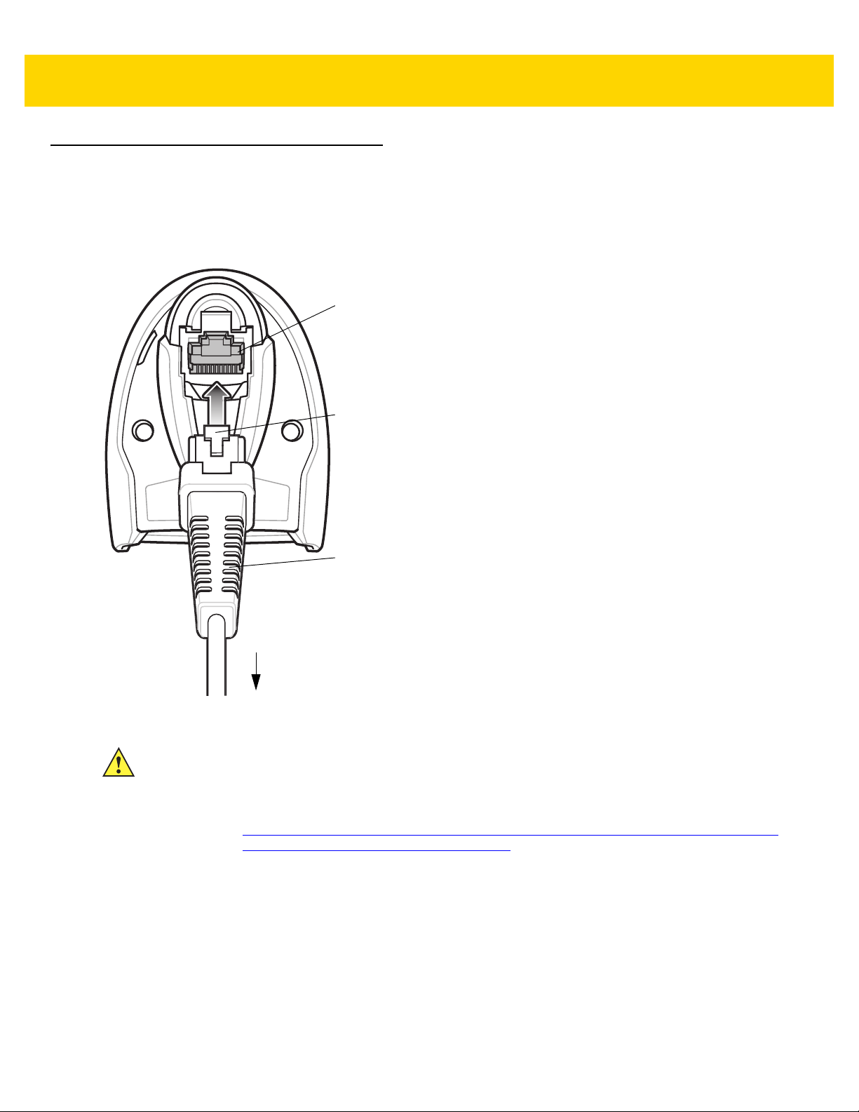
Setting Up the Digital Scanner
Interface cable
modular connector
To host
Cable interface port
Interface cable modular
connector clip
Installing the Interface Cable
1. Insert the interface cable modular connector into the interface cable port on the rear of the digital scanner until
you hear a click.
Getting Started 1 - 3
Figure 1-2 Installing the Cable - DS8108
IMPORTANT Insert the cable into the cable interface port until a click sounds.
If you already have existing non shielded cables from legacy products (such as the LS2208) they
can be reused. However, be aware that the shielded cables provide improved ESD performance.
For regional information about cables and cable compatibility, go to the Zebra Partner Portal at:
https://partnerportal.zebra.com/PartnerPortal/product_services/downloads_z/barcode_scanners/
Universal-Cable-Guide-Bar-Code-Scanners.xlsx.
2. Gently tug the cable to ensure the connector is secure.
3. Connect the other end of the interface cable to the host (see the specific host chapter for information on host
connections).
Page 30
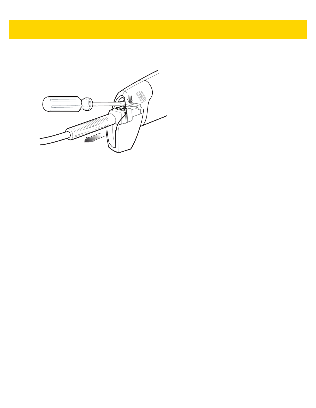
1 - 4 DS8108 Digital Scanner Product Reference Guide
Removing the Interface Cable
1. Press the cable’s modular connector clip through the access slot in the digital scanner’s base.
Figure 1-3 Removing the Cable
2. Carefully slide out the cable.
3. Follow the steps for Installing the Interface Cable to connect a new cable.
Connecting Power (if required)
If the host does not provide power to the digital scanner, connect an external power supply.
1. Plug the power supply into the power jack on the interface cable.
2. Plug the other end of the power supply into an AC outlet.
Configuring the Digital Scanner
To configure the digital scanner use the bar codes included in this manual, or use the 123Scan configuration
program. See Chapter 9, User Preferences & Miscellaneous Options , and Chapter 11, Symbologies for information
about programming the digital scanner using bar code menus. See Chapter 16, 123Scan and Software Tools for
information on using this configuration program. Also see each host-specific chapter to set up connection to a
specific host type.
Page 31

CHAPTER 2 DATA CAPTURE
Beeper
LED
Trigger
Scan Window
Introduction
This chapter provides beeper and LED definitions, techniqu es involved in scanning bar codes, general instructions
and tips about scanning, and decode ranges.
Figure 2-1 Parts of the DS8108
Page 32

2 - 2 DS8108 Digital Scanner Product Reference Guide
Beeper and LED Indicators
In addition to beep sequences, the digital scanner uses a two-color LED to indicate status.
Table 2-1 defines beep sequences that occur du ring both normal scanning and while programming the digital
scanner; LED colors that display during scanning.
Table 2-1 Digital Scanner Beeper and LED Indications
Beeper Sequence LED Indication
Standard Use
Low/medium/high beeps Green Power up.
Scanning
Medium beep
(or as configured)
None Green solid Presentation (Hands-free) Mode on.
None No LED; green LED is
Low/low/low/extra low
beeps
Four long low beeps Red A transmission error occurred. The data is ignored.
Five long low beeps Red Conversion or format error.
None Red (fast blink)) on
Parameter Programming
Long low/long high beeps Red Input error; incorrect bar code or
High/low beeps Green Number expected. Enter value using numeric bar
Green flash A bar code was successfully decoded. (See
Preferences Parameter Defaults on page 9-2
programming beeper sounds.)
Presentation (Hands-free) Mode off.
turned off
Red Parity error.
This occurs if a unit is not properly configured. Check
option setting.
Scanner is disabled by a host command to the
trigger pull
scanner.
Cancel
wrong entry, incorrect bar code programming
sequence; remain in program mode.
codes.
scanned,
User
for
High/low/high/low beeps Green Successful program exit with change in the parameter
setting.
ADF Programming
Low/high/low beeps None ADF transmit error.
High/low beeps Green Number expected. Enter another digit. Add leading
zeros to the front if necessary.
Page 33

Data Capture 2 - 3
Table 2-1 Digital Scanner Beeper and LED Indications (Continued)
Beeper Sequence LED Indication
Low/low beeps Green Alphanumeric expected. Enter another alphanumeric
character or scan the
High/high beeps Green blinking ADF criteria or action is expected. Enter another
criteria or action or scan the
High/low/low beeps Green All criteria or actions cleared for current rule, conti nue
entering rule.
End of Message
Save Rule
bar code.
bar code.
High/low/high/low beeps Green
(turns off blinking)
Long low/long high beeps Red Rule error. Entry error, wrong bar code scanned, or
Low beep Green Deleted last saved rule. The current rule is left intact.
Low/high/high beeps Green All rules deleted.
Long low/long high/long
low/long high beeps
Long low/long high/long
low beeps
Host Specific
USB only
Four high beeps None
RS-232 only
High/high/high/low beeps Red RS-232 receive error.
Red Out of rule memory. Erase some existing rules, then
Green
(turns off blinking)
Rule saved. Rule entry mode exited.
criteria/action list is too long for a rule. Re-enter
criteria or action.
try to save rule again.
Cancel rule entry. Rule entry mode exited because of
an error or the user asked to exit rule entry.
Digital
scanner has not completed initialization. Wait
several seconds and scan again.
High beep None A <BEL> character is received when Beep on <BEL>
is enabled (Point-to-Point mode only).
Page 34

2 - 4 DS8108 Digital Scanner Product Reference Guide
Stand base
Wingnut
One piece scanner
“cup” with flexible
“gooseneck”
Scanning
The DS8108 digital scanner is in Hands-free (presentation) mode when it is placed in the Intellistand. In this mode,
the digital scanner operates in continuous (constant-on) mode, where it automatically de codes a bar code
presented in its field of view.
When the digital scanner is not used for a user-definable period of time, it enters a low power mode in which the
LEDs are turned off or illumination blinks at a low duty cycle until the digital scanner detects an image change (e.g.
motion).
Scanning in Presentation (Hands-free) Mode
The optional stand adds greater flexibility to DS8108 scanning operation. When the scanner is seated in the
scanner cup, the scanner’s built-in sensor places the scanner in Hands-free (presentation) mode. When the
scanner is removed from the stand, it automatically switches to its programmed hand-held triggered mode.
Assembling the Stand
To assemble the stand:
1. Unscrew the wing nut from the bottom of the one piece scanner “cup.”
Figure 2-2 Assembling the Stand
2. Fit the bottom of the gooseneck piece into the opening on the top of the stand base.
3. Tighten the wing nut underneath the base to secure the cup and neck piece to the base.
4. Bend the neck to the desired position for scanning.
Page 35

Data Capture 2 - 5
Two screw-mount holes
Double-sided tape areas
(3 places)
dimensions = 1” x 2”)
Mounting the Stand (optional)
You can attach the base of the scanner’s stand to a flat surface using two screws or double-sided tape (not
provided).
Figure 2-3 Mounting the Stand
Screw Mount
1. Position the assembled base on a flat surface.
2. Screw one #10 wood screw into each screw-mount hole until the base of the stand is secure (see Figure 2-3).
Tape Mount
1. Peel the paper liner off one side of each piece of tape and place the sticky surface over each of the three
rectangular tape holders.
2. Peel the paper liner off the exposed sides of each pi ece of tape and press the stand on a flat surface until it is
secure (see Figure 2-3).
Page 36

2 - 6 DS8108 Digital Scanner Product Reference Guide
Cup
Scanning with the Stand
When the digital scanner is placed in the gooseneck Intellistand it operates in continuous (constant-on) mode,
where it automatically decodes a bar code presented in its field of view.
To operate the scanner in the stand:
1. Ensure the scanner is properly connected to the host (see the ap propriate host chapter for information on h ost
connections).
2. Insert the scanner in the gooseneck Intellistand by placing the front of the scanner into the stand cup.
Figure 2-4 Inserting the Scanner in the Gooseneck Intellistand
3. Adjust the scan angle by bending the stand’s flexible gooseneck body.
4. Present the bar code. Upon successful decode, the scanner beeps and the LED momentarily shuts off. For
more information about beeper and LED definitions, see Table 2-1.
Page 37

Scanning in Hand-held Mode
1D bar code
2D bar code
Aim the digital scanner at a bar code and pull the trigger to decode.
Data Capture 2 - 7
Figure 2-5 Scanning DS8108 -SR in Hand-held Mode
Aiming
When scanning, the digital scanner projects a red LED dot which allows positioning the bar code within its field of
view. See Decode Ranges on page 2-9 for the proper distance to achieve between the digital scanner and a bar
code.
Figure 2-6 Aiming Dot
To scan a bar code, center the symbol and ensure the entire symbol is within the rectangular area formed by the
illumination LEDs.
Figure 2-7 Scanning Orientation with Aiming Dot
Page 38

2 - 8 DS8108 Digital Scanner Product Reference Guide
The digital scanner can also read a bar code presented within the aiming dot not centered. The top examples in
Figure 2-8 show acceptable aiming options, while the bottom examples can not be decoded.
Figure 2-8 Acceptable Aiming
Figure 2-9 Incorrect Aiming
The aiming dot is smaller when the digital scanner is closer to the symb ol and larger when it is farther from the
symbol. Scan symbols with smaller bars or elements (mil size) closer to the digital scanner, and those with larger
bars or elements (mil size) farther from the digital scanner.
The digital scanner beeps to indicate that it successfully decoded the bar code. For more information on beeper
and LED definitions, see Table 2-1.
Page 39

Decode Ranges
DS8108-SR/DL Configurations
Table 2-2 DS8108 -SR/DL Decode Ranges
Bar Code Type Symbol Density
Code 39
Data Capture 2 - 9
DS8108 -SR/DL
Typical Working Ranges
Range In Cm
Near 2.2 5.5
3 mil
Far 5.0 12.8
Near 0.0 0.0
20 mil
Far 36.8 93.6
3 mil
Code 128
100% UPC 13 mil
PDF417
Data Matrix
5 mil
15 mil
5 mil
6.67 mil
7.5 mil
10 mil
Near 2.6 6.5
Far 4.5 11.4
Near 1.6 4.0
Far 8.4 21.4
Near 0.0 0.0
Far 27.1 68.8
Near 0.0 0.0
Far 24.0 61.0
Near 2.3 5.9
Far 6.4 16.3
Near 1.8 4.5
Far 8.5 21.7
Near 2.1 5.3
Far 6.9 17.4
Near 1.1 2.8
Far 9.9 25.2
QR Code
Near 1.0 2.4
10 mil
Far 8.6 21.7
Near 0.1 0.3
20 mil
Far 17.6 44.6
Page 40

2 - 10 DS8108 Digital Scanner Product Reference Guide
DS8108-HC Configurations
Table 2-3 DS8108 -HC Decode Ranges
Bar Code Type Symbol Density
Range In Cm
3 mil
Code 39
20 mil
DS8108 -HC
Typical Working Ranges
Near 1.4 3.4
Far 5.1 13.1
Near 0.0 0.0
Far 22.4 56.8
3 mil
Code 128
100% UPC 13 mil
PDF417
Data Matrix
5 mil
15 mil
5 mil
6.67 mil
5.0 mil
7.5 mil
Near 1.8 4.5
Far 4.1 10.4
Nears 1.2 3.1
Far 8.1 20.5
Near 1.0 2.5
Far 16.9 42.8
Near 0.0 0.0
Far 15.9 40.5
Near 1.5 3.8
Far 6.1 15.5
Near 1.1 2.8
Far 8.1 20.7
Near 1.9 4.8
Far 4.5 11.4
Near 1.3 3.3
Far 6.7 17.1
QR Code
Near 0.6 1.6
10 mil
Far 8.5 21.6
Near 0.6 1.5
10 mil
Far 7.7 19.5
Near 0.0 0.0
20 mil
Far 12.5 31.6
Page 41

Assembling the Document Capture Stand
Document Capture Base
Neck in
Stand Base
Cup
Logo Label
Document
Document Capture Base
Document Guides
Neck
Arm
Cup
Arm
Cup Lock
Screw
Neck Lock Screw
Document
Guides
The DS8108 Document Capture Stand provides Hands-free digital imaging operation. The stand components,
(Figure 2-10), ship in two boxes: Document Capture Base (p/n STND-DC0081C-04); and, Cup and Neck in Stand
Base (p/n 20-66483-02R).
Data Capture 2 - 11
Figure 2-10 Document Capture Stand Components
The stand can be used with the di gital scanne r to capture images o n paper sizes up to A4 and letter (8½ in x 11 in).
Figure 2-11 Document Capture Stand Features
Page 42

2 - 12 DS8108 Digital Scanner Product Reference Guide
Neck Lock
Screw
Neck Lock
Screw Pin
Cup Dock
Cup
Lock
Screw
Base
Neck
Screw
Pin
Slot
Screw
Pin
Tab
Cup Position
Line
Cup Dock
Position Line
Assembly
Figure 2-12 Assembling the Stand
1. Turn the neck lock screw counterclockwise and remove the neck lock screw and neck lock screw pin.
2. Lift the neck out of the base and turn it 180 degrees so that the cup lock screw faces front (as shown).
3. Insert the neck into the base to the highest allowable heig ht for th e ma xim u m fie ld of vie w. The neck can be
lowered as needed to decrease the field of view and increase resolution for smaller sized documents.
4. Replace the neck lock screw pin and neck lock screw. Ensure the screw pin tab fits into the screw pin slot.
5. Turn the neck lock screw clockwise until tight.
6. Remove the cup lock screw from the cup dock, if applicable.
7. Attach the cup to the cup dock, interlocking the grooves.
Figure 2-13 Cup Docking Interlock
IMPORTANT For proper document capture, the position lines on the cup and the cup dock should appear as
shown in the diagram above. The position line on the cup dock should be one groove above the
position line on the cup.
Page 43

8. Replace the cup lock screw and turn clockwise until tight.
9. Slide the assembled stand into the document capture base.
Data Capture 2 - 13
Figure 2-14 Sliding Document Capture Stand Into Base
10. Slide out the Document Capture Base arms.
Figure 2-15 Positioning the Document Capture Stand Arms
11. Place the digital scanner in the cup.
Page 44

2 - 14 DS8108 Digital Scanner Product Reference Guide
A4
Letter
A4
Letter
Center of Page
Indicator
12. Position the paper so that it touches the Document Capture Base. The pap er should align left and right with the
matching guides on the arms of the base to ensure the document is in the correct field of view.
Figure 2-16 Aligning the Paper
NOTE Ensure to line up the edges of the paper with the marks on the document guides, if appropriate.
13. To initiate an image capture or document capture session see Chapter 10, Image Capture Preferences or
Chapter 13, Intelligent Document Capture.
Page 45

CHAPTER 3 MAINTENANCE,
TROUBLESHOOTING, &
TECHNICAL
SPECIFICATIONS
Introduction
This chapter provides suggested digital scanner maintenance, troubleshoo ting, technical specifications, and signa l
descriptions (pinouts).
Maintenance
IMPORTANT Use pre-moistened wipes and do not allow liquid cleaner to pool.
1
When using sodium hypochlorite (bleach) based products always follow the manufacturer’s
recommended instructions: use gloves during application and remove the residue afterwards with
a damp cloth to avoid prolonged skin contact while handling the scanner.
Due to the powerful oxidizing nature of sodium hypochlorite the metal surfaces on the
scanner are prone to oxidation (corrosion) when exposed to this chemical in the liquid
form (including wipes) and should be avoided. In the event that these type of
disinfectants come in contact with metal on the scanner prompt removal with a
dampened cloth after the cleaning step is critical.
Known Harmful Ingredients
The following chemicals are known to damage the plastics on Zebra scanner s and shoul d not come in con tact with
the device:
•Acetone
• Ammonia solutions
• Aqueous or alcoholic alkaline solutions
• Aromatic and chlorinated hydrocarbons
• Benzene
• Carbolic acid
• Compounds of amines or ammonia
• Ethanolamine
•Ethers
• Ketones
•TB-lysoform
• Toluene
• Trichloroethylene.
Page 46

3 - 2 DS8108 Digital Scanner Product Reference Guide
Approved Cleaners for Standard DS8108 Digital Scanners
•
Isopropyl alcohol 70% (including wipes)
•
Bleach/sodium hypochlorite
•
Hydrogen peroxide
•
Mild dish soap
•
Ammonium Chloride.
1 (see important note above)
Approved Disinfectant Cleaners for Healthcare Configurations of the DS8108 Digital Scanners
•
Veridien Viraguard
•
Sodium Hypochlorite 6%
•
Ammonium Chloride 10%
•
Spartan Super HDQL 10
•
Surgipath Cloro-Wipe Towelette
•
PDI Alcohol Prep Pads
•
10% Bleach Solution
•
Clorox® Non-Bleach Disinfecting Wipes
•
Oxivir® Tb Wipes
•
3% Hydrogen Peroxide Solution
•
Sani-Cloth® Bleach Wipes
•
Sani-Cloth® Plus Germicidal Wipes
•
91% Isopropyl Alcohol Solution
•
MetriCide® 28 Day Solution (2.5% Glutaraldehyde)
•
CaviWipes® Disinfecting Towlettes
•
Virex®II 256 Disinfectant Cleaner
•
Cidex® OPA
•
Sani-Cloth® HB Germicidal Wipes
•
Sani-Cloth® PDI AF3 Wipes
1
1 (see important note above)
1 (see important note above)
•
Super San-Cloth® Wipes
•
Windex® Original
•
Windex® Multi-Surface Anti Bacterial Spray
•
Furmula 409® Glass and Surface
•
Hepacide Quat® II
•
Dispatch® Wipes.
Page 47

Maintenance & Technical Specifications 3 - 3
Cleaning the Digital Scanner
Routinely cleaning the exit window is required. A dirty window may affect scanning accuracy. Do not allow any
abrasive material to touch the window.
To clean the scanner:
1. Dampen a soft cloth with one of the approved cleaning agents listed above or use pre-moistened wipes.
2. Gently wipe all surfaces, including the front, back, sides, top and bottom. Never apply liquid directly to the
scanner. Be car eful not to let liquid po ol around the scanner wind ow, trigger, cable connector or any ot her area
on the device.
3. Be sure to clean the trigger and in between the trigger and th e housing (use a cotto n-tipped applicator to reach
tight or inaccessible areas).
4. Do not spray water or other cleaning liquids directly into the exit window.
5. Wipe the scanner exit window with a lens tissue or other material suitable for cleaning optical material such as
eyeglasses.
6. Immediately dry the scanner window after cleaning with a soft non-abrasive cloth to prevent streaking.
7. Allow the unit to air dry before use.
8. Scanner connectors:
a. Dip the cotton portion of a cotton-tipped applicator in isopropyl alcohol.
b. Rub th e cot to n po rtion of the cotton-tipped applicator back-and-forth across the connector on the Zebra
scanner at least 3 times. Do not leave any cotton residue on the connector.
c. Use the cotton-tipped applicator dipped in alcohol to remove any grease and dirt near the connector area.
d. Use a dry cotton tipped applicator and rub the cotton portion of the cotton-tipped applicator back-and-forth
across the connectors at least 3 times. Do not leave any cotton residue on the connectors.
Page 48

3 - 4 DS8108 Digital Scanner Product Reference Guide
Troubleshooting
Table 3-1 Troubleshooting
Problem Possible Causes Possible Solutions
The aiming pattern does not
appear when pressing the
trigger.
No power to the digital scanner. If the configuration requires a power supply,
Incorrect host interface cable is
used.
Interface/power cables are loose. Re-connect cables.
Digital scanner is disabled. For IBM 468x and USB IBM hand-held, IBM
re-connect the power supply.
Connect the correct host interface cable.
table-top, and OPOS modes, enable the digital
scanner via the host interface. Otherwise, see
the technical person in charge of scanning.
Digital scanner
pattern, but does not
decode the bar code.
Digital scanner
code, but does not transmit
the data to the host.
emits aiming
decodes bar
If using RS-232 Nixdorf B mode,
CTS is not asserted.
Aiming pattern is disabled. Enable the aiming pattern. See
Digital scanner
for the correct bar code type.
Bar code symbol is unreadable. Scan test symbols of the same bar code type
The symbol is not completely
inside aiming pattern.
Distance between digital scanner
and bar code is incorrect.
Digital scanner
for the correct host type.
Interface cable is loose. Re-connect the cable.
If the digital scanner emits four
long low beeps, a transmission
error occurred.
This occurs if a unit is not properly
configured or connected to the
wrong host type.
If the digital scanner emits 5 low
beeps, a conversion or format error
occurred.
If the digital scanner emits
low/high/low beeps, it detected an
invalid ADF rule.
is not programmed
is not programmed
Assert CTS line.
Hand-Held
Decode Aiming Pattern on page 5-22
Program the digital scanner to read that type
of bar code. See
to determine if the bar code is defaced.
Move the symbol completely within the aiming
pattern.
Move the symbol completely within the field of
view (AIM pattern does NOT define FOV)
Move the scanner closer to or further from the
bar code. See
Scan the appropriate host type programming
bar code. See the chapter corresponding to
the host type.
Set the scanner's communication parameters
to match the host's setting.
Configure the digital scanner's conversion
parameters properly.
Program the correct ADF rules. Refer to the
Advanced Data Formatting Programmer
Guide.
Chapter 12, Symbologies
Decode Ranges on page 2-9
.
.
.
Page 49

Table 3-1 Troubleshooting (Continued)
Problem Possible Causes Possible Solutions
Maintenance & Technical Specifications 3 - 5
Host displays scanned data
incorrectly.
Digital scanner
emits short
low/short medium/short high
beep sequence (power-up
beep sequence) more than
once.
Digital scanner
emits 4 short
high beeps during decode
attempt.
Digital scanner
emits
Low/low/low/extra low
beeps when not in use.
Digital scanner
emits
low/high beeps during
programming.
Digital scanner
emits
low/high/low/high beeps
during programming.
Digital scanner
to work with the host.
is not programmed
Scan the appropriate host type programming
bar code.
For RS-232, set the digital scanner's
communication parameters to match the host's
settings.
For a Keyboard Wedge configuration, program
the system for the correct keyboard type, and
turn off the CAPS LOCK key.
Program the proper editing options (e.g.,
UPC-E to UPC-A Conversion).
The USB bus may put the digital
Normal during host reset.
scanner in a state where power to
the scanner is cycled on and off
more than once.
Digital scanner
has not completed
Wait several seconds and scan again.
USB initialization.
RS-232 receive error. Normal during host reset. Otherwise, set the
digital scanner's RS-232 parity to match the
host setting.
Input error, incorrect bar code or
Cancel
bar code was scanned.
Out of host parameter storage
Scan the correct numeric bar codes within
range for the parameter programmed.
Scan
Default Parameters on page 5-5
.
space.
Out of memory for ADF rules. Reduce the number of ADF rules or the
number of steps in the ADF rules.
During programming, indicates out
of ADF parameter storage space.
Erase all rules and re-program with shorter
rules.
Digital scanner
emits
low/high/low beeps.
Digital scanner
emits a
power-up beep after
changing USB host type.
Digital scanner
emits one
high beep when not in use.
ADF transmit error. Refer to the Advanced Data Formatting Guide
for information.
Invalid ADF rule is detected. Refer to the Advanced Data Formatting Guide
for information.
The USB bus re-established power
Normal when changing USB host type.
to the digital scanner.
In RS-232 mode, a <BEL>
character was received and Beep
Normal when
Beep on <BEL>
is enabled and
the digital scanner is in RS-232 mode.
on <BEL> option is enabled.
Page 50

3 - 6 DS8108 Digital Scanner Product Reference Guide
Table 3-1 Troubleshooting (Continued)
Problem Possible Causes Possible Solutions
Digital scanner
emits
frequent beeps.
Digital scanner
emits five
long low beeps after a bar
code is decoded.
No power to the scanner. Check the system power. If the configuration
requires a power supply, re-connect the power
supply.
Incorrect host interface cable is
used.
Verify that the correct host interface cable is
used. If not, connect the correct host interface
cable.
Interface/power cables are loose. Check for loose cable connections and
re-connect cables.
Conversion or format error was
detected.
Ensure the scanner conversion parameters
are properly configured.
The scanner conversion
parameters are not properly
configured.
Conversion or format error was
detected.
Change the ADF rule, or ch ange to a host that
can support the ADF rule.
An ADF rule was set up with
characters that can't be sent for the
host selected.
Conversion or format error was
detected.
Change the bar code, or change to a host that
can support the bar code.
A bar code was scanned with
characters that can't be sent for
that host.
NOTE If after performing these checks the digital scanner still experiences problems, contact the distributor or
call support.
Dump Scanner Parameters
To debug a scanner issue, scan the following bar code with the scanner connected in USB HID keyboard mode to
Microsoft
asset tracking information and parameter settings to a text document.
Refer to the parameter numbers in Appendix A, Standard Parameter Defaults to interpret the parameter/attribute
numbers in the output.
®
Windows Notepad or Wordpad, or via RS-232 to Windows Hyperterminal. This outputs all the scanner's
NOTE Use 123Scan if available as an alternative to using this feature. 123Scan is the preferable method for
outputting scanner information.
NOTE For proper formatting, it may be necessary to first scan <DATA> <SUFFIX 1> (1) on page 9-34.
Dump Scanner Parameters
Page 51

Maintenance & Technical Specifications 3 - 7
Send Versions
Report Software Ve rsion
Scan the following bar code to send the version of software installed in the scanner.
Report Software Version
Serial Number
Scan the following bar code to send the scanner serial number to the host.
Serial Number
Manufacturing Information
Scan the following bar code to send the scanner manufacturing information to the host.
Manufacturing Information
Page 52

3 - 8 DS8108 Digital Scanner Product Reference Guide
Technical Specifications
Table 3-2 Technical Specifications
Item Description
Physical Characteristics
Dimensions 6.6 in. H x 2.6 in. W x 4.2 in. D
16.8 cm. H x 6.6 cm. W x 10.7 cm. D
Weight
DS8108-SR/DL
DS8108-HC
Available Colors Twilight Black, Nova White, Healthcare White (DS8108-HC)
Power
DS8108-SR
DS8108-HC
DS8108-DL
5.4 oz./154 g
5.5 oz./156 g
5 VDC +/- 10% @ 470 mA (RMS typical)
5 VDC +/- 10% @ 470 mA (RMS typical)
5 VDC +/- 10% @ 470 mA (RMS typical)
Supported Host Interfaces USB, RS232, Keyboard Wedge, TGCS (IBM) 46XX over RS485
Keyboard Support Supports over 90 international keyboards
FIPS Security Certification Certified Compliant with FIPS 140-2
User Indicators Direct Decode Indicator, Good Decode LEDs, Rear View LEDs,
Beeper (Adjustable Tone & Volume), Battery Indicator
Performance Characteristics
Light Source
DS8108-SR
DS8108-HC
DS8108-DL
Illumination
DS8108-SR/DL
DS8108-HC
Field of View
(Horizontal x Vertical) Nominal
Image Sensor 1,280 x 960 pixels
Minimum Print Contrast 16% minimum reflective difference
Aiming pattern: 617 nm LED / Illumination: 660 nm LEDs
Aiming pattern: 528 nm LED/ Illumination: Warm white LEDs
Aiming pattern: 617 nm LED / Illumination: 660 nm LEDs
Two 645n m red LEDs
Two warm white LEDs
48° H x 37° V
Skew Tolerance +/- 60°
Pitch Tolerance +/- 60°
Roll Tolerance 0-360°
Page 53

Maintenance & Technical Specifications 3 - 9
Table 3-2 Technical Specifications (Continued)
Item Description
Image Capture
Graphics Format Support Images can be exported as Bitmap, JPEG, or TIFF
Resolution (A4 document) 109 PPI
Minimum Element Resolution Code 39 - 3.0 mil; Code 128 - 3.0 mil; Data Matrix - 6.0 mil; QR
Code - 6.0 mil; PDF - 5.0 mil
User Environment
DS8108-SR/DL Temperatures Operating Temperature: 32° to 122°F / 0° to 50°C
Charging Temperature: 32° to 104°F / 0° to 40°C
Storage Temperature -40° to 158°F / -40° to 70°C
Humidity 5% to 95% RH, non-condensing
Drop Specification (Scanner) Designed to withstand multiple drops at 6.0 ft./1.8 m to concrete
Tumble Specification (Scanner) Designed to withstand 2,000 tumbles in 1.5 ft./0.5 m tu mb le r
Note: 1 tumble = 0.5 cycle
Ambient Light Immunity 0 to 9000 Foot Candles/0 to 96,840 Lux
Environmental Sealing Scanner rated IP42
Electrostatic Discharge (ESD) ESD per EN61000-4-2, +/-15 KV Air, +/-8 KV Direct, +/-8 KV
Indirect
Accessories - see Related Product Line Configurations/Accessories on page xx
Symbol Decode Capability
1D Code 39, Code 128, Code 93, Codabar/NW7, Code 11, MSI,
UPC/EAN, I 2 of 5, Korean 3 of 5, GS1 DataBar , Base 32 (Ita lian
Pharma)
2D PDF417, Micro PDF417, Composite Codes, TLC-39, Aztec,
DataMatrix, MaxiCode, QR Code, Micro QR, Chinese Sensible
(Han Xin), Postal Codes
DigiMarc Digital watermark technology
Page 54

3 - 10 DS8108 Digital Scanner Product Reference Guide
Table 3-2 Technical Specifications (Continued)
Item Description
Minimum Resolution
DS8108-SR/DL
Code 39 3 mil
UPC 40% 5.2 mil
PDF417 4 mil
Data Matrix 6 mil
DS8108-HC
Utilities and Management
123Scan Progr ams scanner parameters, upgrades firmware, provides
Symbol Scanner SDK Generates a fully-featured scanner application, including
Scanner Management Service (SMS) Remotely manages your Zebra scanner and queries its asset
Code 39 3 mil
UPC 40% 5.2 mil
PDF417 4 mil
Data Matrix 5 mil
See
Decode Ranges on page 2-9
scanned bar code data and prints reports. See Chapter 17,
123Scan and Software Tools.
documentation, drivers, test utilities and sample source code.
www.zebra.com/ScannerSDKforWindows
information.
www.zebra.com/sms
for typical working ranges.
Page 55

Digital Scanner Signal Descriptions
Cable Interface Port
PIN 10PIN 1
Bottom of Scanner
Maintenance & Technical Specifications 3 - 11
Figure 3-1 Digital Scanner Cable Pin-outs
The signal descriptions in Table 3-3 apply to the connectors on the DS8108 digital scanner and are for reference
only .
Table 3-3 DS8108Digital Scanner Signal Pin-outs
Pin IBM RS-232 Keyboard Wedge USB
1
2
3
4
5
6
7
8
9
10
Cable ID Cable ID Cable ID Cable ID
Power (+5V) Power (+5V) Power (+5V) Power (+5V)
Ground Ground Ground Ground
IBM_OUT TxD KeyClock Reserved
IBM_IN RxD TermData D +
IBM_T/R RTS KeyData Reserved
Reserved CTS TermClock D Reserved Reserved Reserved Reserved
See note
See note
Note: EAS configurations use pins 9 and 10 for an EAS antenna. For other
configurations pins 9 and 10 are open.
Page 56

3 - 12 DS8108 Digital Scanner Product Reference Guide
Page 57

CHAPTER 4 USB INTERFACE
*Enable Parameter
Feature/option* Indicates default
Introduction
This chapter describes how to set up the scanner with a USB host. The scann er connects directly to a USB h ost, or
a powered USB hub, which powers it. No additional power supply is required.
The scanner ships with the settings shown in Table 4-1 on page 4-4 (also see Appendix A, Standard Parameter
Defaults for all defaults). If the default values suit requirements, programming is not necessary.
Setting Parameters
To set feature values, scan a single bar code or a short bar code sequence. The settings are stored in non-volatile
memory and are preserved even when th e sca nn e r po wer s do wn .
NOTE Most computer monitors allow scanning bar codes directly on the screen. When scanning from the screen,
be sure to set the document magnification to a level where you can see the bar code clearly, and bars
and/or spaces do not merge.
To return all features to default values, scan Set Factory Defaults on page 9-5. Throughout the programming bar
code menus, asterisks (
*) indicate default values.
Scanning Sequence Examples
In most cases scanning one bar code sets the parameter value. For example, to set the USB keystroke delay to
medium, scan the Medium Delay (20 msec) bar code under USB Keystroke Delay on page 4-7. The scanner
issues a fast warble beep and the LED turns green, signifying a successful parameter entry.
Other parameters require scanning several bar codes. See the parameter descriptions for this procedure.
Page 58

4 - 2 DS8108 Digital Scanner Product Reference Guide
Interface cable
USB Series A
shielded connector
Errors While Scanning
Unless otherwise specified, to correct an error during a scanning sequence, just re-scan the correct para meter.
Connecting a USB Interface
Figure 4-1 USB Connection.
NOTE When connecting via USB use the shielded connector cable (e.g., p/n CBA-U21-S07ZAR). Refer to
Solution Builder for guidance about cables.
The scanner connects to USB-capable hosts including:
•
Apple™ desktop and notebooks
•
Other network computers that support more than one keyboard.
The following operating systems support the scanner through USB:
•
Windows® XP, 7, 8, 10
•
MacOS 8.5 - MacOS 10.6
•
IBM 4690 OS
•
Linux.
The scanner also interfaces with other USB hosts that support USB Human Interface Devices (HID).
Page 59

USB Interface 4 - 3
To set up the scanner:
NOTE Interface cables vary depending on configuration. The connectors illustrated in Figure 4-1 are examples
only. The connectors may be different than those illustrated, but the steps to connect the scanner are the
same.
1. Connect the modular connector of the USB interface cable to the cable interface port on the scanner. See
Installing the Interface Cable on page 1-3.
2. Plug the series A connector in the USB host or hub, or plug the Plus Power connector in an available port of
the IBM SurePOS terminal.
3. The scanner automatically detects the host and uses the default USB device type. If the default (*) does not
meet your requirements, select another USB device type by scanning the appropriate bar code from USB
Device Type on page 4-5.
4. On first installation when using Windows, the software may prompt to select or install the Human Interface
Device driver. To install this driver, provided by Windows, click Next at all choices and click Finished on the
last choice. The scanner powers up during this installation.
5. To modify any other parameter options, scan the appropriate bar codes in this chapter.
If problems occur with the system, see Troubleshooting on page 3-4.
Page 60

4 - 4 DS8108 Digital Scanner Product Reference Guide
USB Parameter Defaults
Table 4-1 lists defaults for USB host parameters. Change these values in one of two ways:
•
Scan the appropriate bar codes in this chapte r. The new value replaces the standard default value in
memory. To recall default parameter values, see Default Parameters on page 9-5.
•
Configure the scanner using the 123Scan configuration program. See Chapter 16, 123Scan and Software
Tools.
NOTE See Appendix A, Standard Parameter Defaults for all user preference, host, symbology, and
miscellaneous default parameters.
Table 4-1 USB Interface Parameter Defaults
Parameter Default
USB Host Parameters
USB Device Type USB Keyboard HID
Symbol Native API (SNAPI) Status Handshak ing Enable
USB Keystroke Delay No Delay
USB Caps Lock Override Disable
Bar Codes with Unknown Characters Send Bar Codes with
Unknown Characters
USB Convert Unknown to Code 39 Disable
USB Fast HID Enable
USB Polling Interval 3 msec
Keypad Emulation Enable
Quick Keypad Emulation Enable
Keypad Emulation with Leading Zero Enable
USB FN1 Substitution Disable
Page
Number
4-5
4-7
4-7
4-8
4-8
4-9
4-9
4-10
4-12
4-12
4-13
4-13
Function Key Mapping Disable
Simulated Caps Lock Disable
Convert Case None
USB Static CDC Enable
TGCS (IBM) USB Beep Directive Ignore
TGCS (IBM) USB Bar Code Configuration Directive Ignore
TGCS (IBM) USB Specification Version Version 2.2
4-14
4-14
4-15
4-15
4-16
4-16
4-17
Page 61
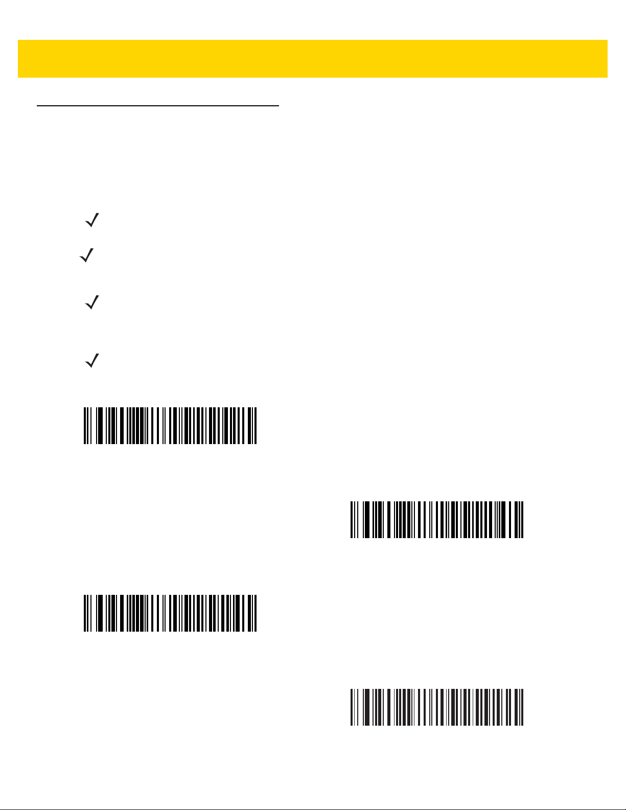
USB Host Parameters
USB Device Type
Scan one of the following bar codes to select the USB device type. To select a country keyboard type for the USB
Keyboard HID host, see Appendix G, Country Codes..
NOTE When changing USB Device Types, the scanner resets and issues the standard startup beep sequences.
NOTE When connecting two scanners to a host, IBM does not allow selecting two of the same device type. If you
require two connections, select IBM Table-top USB for one scanner and IBM Hand-held USB for the
second scanner.
NOTE Select IBM Hand-held USB to disable data transmission when an IBM register issues a Scan Disable
command. Aim, illumination, and decoding is still permitted. Select IBM OPOS (IBM Hand-held USB with
Full Scan Disable) to completely shut off the scanner when an IBM register issues a Scan Disable
command, including aim, illumination, decoding, and data transmission.
NOTE To select the Toshiba TEC device type, refer to the Toshiba TEC Programmer’s Guide.
USB Interface 4 - 5
*
USB Keyboard HID
IBM Hand-held USB
IBM Table-top USB
IBM OPOS
(IBM Hand-held USB with Full Scan Disable)
Page 62

4 - 6 DS8108 Digital Scanner Product Reference Guide
USB Device Type (continued)
NOTE Before selecting USB CDC Host on page 4-6 or SSI over USB CDC on page 4-6, install the appropriate
USB CDC Driver on the host to ensure the scanner does not stall during power up (due to a failure to
enumerate USB). Go to www.zebra.com/support, Support & Downloads > Barcode Scanners > USB
CDC Driver, select the appropriate Windows platform, and download the appropriate CDC Driver (64 bit
or 32 bit).
To recover a stalled scanner:
Install the USB CDC Driver
or
After power-up, hold the trigger for 10 seconds, which allows the scanner to power up using an
USB configuration. Upon power-up, scan another USB Device Type.
USB CDC Host
alternate
Symbol Native API (SNAPI) with Imaging Interface
SSI over USB CDC
Symbol Native API (SNAPI) without Imaging Interface
Page 63

USB Interface 4 - 7
Symbol Native API (SNAPI) Status Handshaking
After selecting a SNAPI interface as the USB device type, scan one of the following bar codes to select whethe r to
enable or disable status handshaking.
*Enable SNAPI Status Handshaking
Disable SNAPI Status Handshaking
USB Keystroke Delay
Scan one of the following bar codes to set the delay , in milliseconds, between emulated keystrokes. Select a longer
delay for hosts that require slower data transmission.
*No Delay
Medium Delay (20 msec)
Long Delay (40 msec)
Page 64

4 - 8 DS8108 Digital Scanner Product Reference Guide
USB Caps Lock Override
This option applies only to the
the data regardless of the state of the Caps Lock key. This setting is always enabled for the Japanese Windows
(ASCII) keyboard type and can not be disabled.
Override Caps Lock Key
(Enable)
USB Keyboard HID
device. Scan Override Caps Lock Key to preserve the case of
*Do Not Override Caps Lock Key
(Disable)
Bar Codes with Unknown Characters
This option applies only to the
does not recognize. Scan Send Bar Codes With Unknown Characters to send all bar code data except for
unknown characters. The scanner issues no error beeps.
Scan Do Not Send Bar Codes With Unknown Characters for IBM devices to prevent sending bar codes
containing at least one unknown character to the host, or for
characters up to the unknown character. The scanner issues an error beep.
USB Keyboard HID
and IBM devices. Unknown characters are characters the host
USB Keyboard HID
devices to send the bar code
*Send Bar Codes with Unknown Characters
Do Not Send Bar Codes with Unknown Characters
Page 65

USB Interface 4 - 9
USB Convert Unknown to Code 39
This option applies only to the IBM hand-held, IBM table-top, and OPOS devices. Scan one of the following bar
codes to enable or disable converting unknown bar code type data to Code 39.
Enable Convert Unknown to Code 39
*Disable Convert Unknown to Code 39
USB Fast HID
Scan Enable USB Fast HID to transmit
NOTE Disable this if there are problems with transmission.
*Enable USB Fast HID
USB HID
data at a faster rate.
Disable USB Fast HID
Page 66

4 - 10 DS8108 Digital Scanner Product Reference Guide
USB Polling Interval
Scan one of the following bar codes to set the polling interval, which is the rate at which data transmits between the
scanner and host computer. A lower number indicates a faster data rate.
NOTE When changing the USB polling interval, the scanner restarts and issues a power-up beep sequence.
IMPORTANT Ensure the host supports the selected data rate.
1 msec
*3 msec
5 msec
2 msec
4 msec
Page 67

USB Polling Interval (continued)
6 msec
USB Interface 4 - 11
7 msec
8 msec
9 msec
Page 68

4 - 12 DS8108 Digital Scanner Product Reference Guide
Keypad Emulation
Scan Enable Keypad Emulation to send all characters as ASCII sequences over the numeric keypad.
For example, ASCII A transmits as “ALT make” 0 6 5 “ALT Break”.
NOTE If your keyboard type is not listed in the country code list (see Country Codes on page G-1),
disable Quick Keypad Emulation and enable Keypad Emulation.
*Enable Keypad Emulation
Disable Keypad Emulation
Quick Keypad Emulation
This option applies only to the
Keypad Emulation for a quicker method of emulation using the numeric keypad where ASCII sequences are only
sent for ASCII characters not found on the keyboard.
USB Keyboard HID
device when Keypad Emulation is enabled. Scan Enable Quick
*Enable Quick Keypad Emulation
Disable Quick Keypad Emulation
Page 69

USB Interface 4 - 13
Keypad Emulation with Leading Zero
Scan Enable Keypad Emulation with Leading Zero to send character sequences sent over the numeric keypad
as ISO characters which have a leading zero. For example, ASCII A transmits as “ALT MAKE” 0 0 6 5 “ALT
BREAK”.
*Enable Keypad Emulation with Leading Zero
Disable Keypad Emulation with Leading Zero
USB Keyboard FN1 Substitution
This option applies only to the
replace any FN1 character in a GS1 128 bar code with a user-selected Key Category and value.
See FN1 Substitution Values on page 9-36 to set the Key Category and Key Value.
Enable USB Keyboard FN1 Substitution
USB Keyboard HID
device. Scan Enable USB Keyboard FN1 Substitution to
*Disable USB Keyboard FN1 Substitution
Page 70

4 - 14 DS8108 Digital Scanner Product Reference Guide
Function Key Mapping
ASCII values under 32 are normally sent as a control-ke y se quen ce (se e Table D-1 on page D-1). Scan Enable
Function Key Mapping to send the keys in bold in place of the standard key mapping. Table entries that do not
have a bold equivalent remain the same regardless of whether you enable this parameter.
Enable Function Key Mapping
*Disable Function Key Mapping
Simulated Caps Lock
Scan Enable Simulated Caps Lock to inver t upper and lower case characters on the ba r code as if the Caps Lock
state is enabled on the keyboard. This inversion occurs regardless of the keyboard’s Caps Lock state.
NOTE Simulated Caps Lock applies to ASCII characters only.
NOTE Do not enable this if USB Caps Lock Override on page 4-8 is enabled.
Enable Simulated Caps Lock
*Disable Simulated Caps Lock
Page 71

Convert Case
Scan one of the following bar codes to convert all bar code data to the selected case.
NOTE Convert Case applies to ASCII characters only.
*No Case Conversion
USB Interface 4 - 15
Convert All to Upper Case
Convert All to Lower Case
USB Static CDC
When disabled, each device connected consumes another COM port (first device = COM1,
second device = COM2, third device = COM3, etc.)
When enabled, each device connects to the same COM port.
*Enable USB Static CDC
Disable USB Static CDC
Page 72

4 - 16 DS8108 Digital Scanner Product Reference Guide
TGCS (IBM) USB Beep Directive
The host can send a beeper configuration request to the scanner. Scan Ignore Beep Directive to prevent the
scanner from processing the host request. All directives are still acknowledged to the USB host as if they were
processed.
Honor Beep Directive
*Ignore Beep Directive
TGCS (IBM) USB Bar Code Configuration Directive
The host can enable and disable code types. Scan Ignore Bar Code Configuration Directive to prevent the
scanner from processing the host request. All directives are still acknowledged to the USB host as if they were
processed.
Honor Bar Code Configuration Directive
*Ignore Bar Code Configuration Directive
Page 73

USB Interface 4 - 17
TGCS (IBM) USB Specification Version
Select IBM Specification Level Version 0 (Original) to send the following code types as Unknown:
•
Data Matrix
•
GS1 Data Matrix
•
QR Code
•
GS1 QR
•
MicroQR Code
•
Aztec
Select IBM Specification Level Version 2.2 to send the code types with the appropriate IBM identifiers.
IBM Specification Level Version 0 (Original)
ASCII Character Sets
See Appendix D, ASCII Character Sets for the following information:
•
Table D-1, ASCII Character Set on page D-1
•
Table D-2, ALT Key Character Set on page D-6
•
Table D-3, GUI Key Character Set on page D-7
•
Table D-4, PF Key Character Set on page D-9
•
Table D-5, F Key Character Set on page D-10
•
Table D-6, Numeric Key Character Set on page D-11
*IBM Specification Level Version 2.2
•
Table D-7, Extended Key Character Set on page D-12
Page 74

4 - 18 DS8108 Digital Scanner Product Reference Guide
Page 75

CHAPTER 5 SSI INTERFACE
Introduction
This chapter describes the system requirements of the Simple Serial Interface (SSI), which provides a
communications link between Zebra decoders (e.g., scan engines, slot scanners, hand-held scanners,
two-dimensional scanners, Hands-free scanners, and RF base stations) and a serial host. It provides the means
for the host to control the decoder or scanner.
Communication
All communication between the scanner and host occurs over the hardware interface lines using the SSI protocol.
Refer to the Simple Serial Interface Programmer’s Guide, p/n 72E-40451-xx, for more information on SSI.
The host and the scanner exchange messages in packets. A packet is a collection of bytes framed by the proper
SSI protocol formatting bytes. The maximum number of bytes per packet that the SSI protocol allows for any
transaction is 257 (255 bytes + 2 byte checksum).
Depending on the configuration, the scanner can send decode data as ASCII data (unpacketed), or as part of a
larger message (packeted).
SSI performs the following functions for the host device:
•
Maintains a bi-directional interface with the scanner
•
Allows the host to send commands that control the scanner
•
Passes data from the scanner to a host device in SSI packet format or straight decode message.
The SSI environment consists of a scanner, a serial cable which attaches to the host device, and if required, a
power supply.
SSI transmits all decode data including special formatting (e.g., AIM ID). Parameter sett ings can control the form at
of the transmitted data.
The scanner can also send parameter information, product identification information, or event codes to the host.
All commands sent between the scanner and host must use the format described in the SSI Message Formats
section. SSI Transactions on page 5-3 describes the required sequence of messages in specific cases.
Page 76

5 - 2 DS8108 Digital Scanner Product Reference Guide
SSI Commands
Table 5-1 lists all the SSI opcodes the scanner supports. The host transmits opcodes designated type H. The
scanner (decoder) transmits type D opcodes, and either can transmit Host/Decoder (H/D) types.
Table 5-1 SSI Commands
Name Type Opcode Description
AIM_OFF H 0xC4 Deactivate aim pattern.
AIM_ON H 0xC5 Activate aim pattern.
BEEP H 0xE6 Sound the beeper.
CAPABILITIES_REPLY D 0xD4 Reply to CAPABILITIES_REQUEST; contains a list of the
capabilities and commands the decoder supports.
CAPABILITIES_REQUEST H 0xD3 Request capabilities report from the decoder.
CMD_ACK H/D 0xD0 Positive acknowledgment of received packet.
CMD_NAK H/D 0xD1 Negative acknowledgment of received packet.
DECODE_DATA D 0xF3 Decode data in SSI packet format.
EVENT D 0xF6 Event indicated by associated event code.
LED_OFF H 0xE8 De-activate LED output.
LED_ON H 0xE7 Activate LED output.
PARAM_DEFAULTS H 0xC8 Set parameter default values.
PARAM_REQUEST H 0xC7 Request values of certain parameters.
PARAM_SEND H/D 0xC6 Send parameter values.
REPLY_REVISION D 0xA4 Reply to REQUEST_REVISION, contains the decoder's
software/hardware configuration.
REQUEST_REVISION H 0xA3 Request the decoder's configuration.
SCAN_DISABLE H 0xEA Prevent the operator from scanning bar codes.
SCAN_ENABLE H 0xE9 Permit bar code scanning.
SLEEP H 0xEB Request to place the decoder into low power.
START_DECODE H 0xE4 Tell the decoder to attempt to decode a bar code.
STOP_DECODE H 0xE5 Tell the decoder to abort a decode attempt.
WAKEUP H N/A Wake the decoder from low power mode.
For details of the SSI protocol, refer to the Simple Serial Interface Programmer's Guide.
Page 77

SSI Transactions
General Data Transactions
ACK/NAK Handshaking
If you enable ACK/NAK handshaking (the default), all packeted messages must have a CMD_ACK or CMD_NAK
response, unless the command description states otherwise. Zebra recommends leaving this handshaking
enabled to provide feedback to the host. Raw decode data and WAKEUP do not use ACK/NAK handshaking since
they are not packeted data.
Following is an example of a problem which can occur if you dis abl e ACK/NAK handshaking:
•
The host sends a PARAM_SEND message to the scanner to change the baud rate from 9600 to 19200.
•
The scanner cannot interpret the message.
•
The scanner does not implement the change the host requested.
•
The host assumes that the parameter change occurred and acts accordingly.
SSI Interface 5 - 3
•
Communication is lost because the change did not occur on both sides.
If you enable ACK/NAK handshaking, the following occurs:
•
The host sends a PARAM_SEND message.
•
The scanner cannot interpret the message.
•
The scanner CMD_NAKs the message.
•
The host resends the message.
•
The scanner receives the message successfully, responds with CMD_ACK, and implements parameter
changes.
Page 78

5 - 4 DS8108 Digital Scanner Product Reference Guide
Decoder
Data is captured
by decoder
Host
(1)
DECODE_DATA
(2)
CMD_ACK
message sent
Decoder
Data is captured
by decoder
Host
ASCII data
Decoded Data Transmission
The Decode Data Packet Format parameter controls how decode data is sent to the host. Set this parameter to
send the data in a DECODE_DATA packet. Clear this parameter to transmit the data as raw ASCII data.
NOTE When transmitting decode data as raw ASCII data, ACK/NAK handshaking does not apply regardless of
the state of the ACK/NAK handshaking parameter.
ACK/NAK Enabled and Packeted Data
The scanner sends a DECODE_DATA message after a successful decode. The scanner waits for a prog rammable
timeout for a CMD_ACK response. If it does not receive the response, the scanner tries to send two more times
before issuing a host transmission error. If the scanner receives a CMD_NAK from the host, it may attempt a retry
depending on the cause field of the CMD_NAK message.
ACK/NAK Enabled and Unpacketed ASCII Data
Even if ACK/NAK hand shaking is e nab led, no ha ndshaking occurs becau se handshaking a pplies on ly to p acketed
data. In this example the packeted_decode parameter is disabled.
Page 79

SSI Interface 5 - 5
Decoder
Data is captured
by decoder
Host
(1)
DECODE_DATA
message sent
Decoder
Data is captured
by decoder
Host
(1)
ASCII data sent
ACK/NAK Disabled and Packeted DECODE_DATA
In this example ACK/NAK does not occur even though packeted_decode is enabled because the ACK/NAK
handshaking parameter is disabled.
ACK/NAK Disabled and Unpacketed ASCII Data
The decoder sends captured data to the host.
Communication Summary
RTS/CTS Lines
All communication must use RTS/CTS handshaking as described in the Simple Serial Interface Programmer’s
Guide, p/n 72E-40451-xx. If bypassing hardware handshaking, the host must send the WAKEUP command before
all other communication or the first byte of a message can be lost during the scan ner wakeup sequence. Zebra
recommends not bypassing RTS/CTS hardware handshaking.
ACK/NAK Option
ACK/NAK handshaking is enabled by default and Zebra recommends leaving it enabled. Disabling this can cause
communication problems, as handshaking is the only acknowledgment that a message was received correctly.
ACK/NAK is not used with unpacketed decode data regardless of whether it is enabled.
Number of Data Bits
All communication with the scanner must use 8-bit data.
Page 80

5 - 6 DS8108 Digital Scanner Product Reference Guide
Serial Response Timeout
The Host Serial Response Timeout parameter determines how long to wait for a handshaking response before
trying again or aborting further attempts. Set the same value for both the host and scanner.
NOTE You can temporarily change the Host Serial Response Timeout when the host takes longer to process an
ACK or longer data string. Zebra does not recommend frequent permanent changes due to limited write
cycles of non-volatile memory.
Retries
The host resends data twice after the initial send if the scanner does not respond with an ACK or NAK (if ACK/NAK
handshaking is enabled), or response data (e.g., PARAM_SEND, REPLY_REVISION). If the scanner replies with a
NAK RESEND, the host resends the data. All resent messages must have the resend bit set in the Status byte.
The scanner resends data two times after the initial send if the host fails to reply with an ACK or NAK (if ACK/NAK
handshaking is enabled).
Baud Rate, Stop Bits, Parity, Response Timeout, ACK/NAK Handshaking
If you use PARAM_SEND to change these serial parameters, the ACK response to the PARAM_SEND uses the
previous values for these parameters. The new values then take ef fect for the next transaction.
Errors
The scanner issues a communication error when:
•
The CTS line is asserted when the scanner tries to transmit, and is still asserted on each of two successive
retries
•
The scanner does not receive an ACK or NAK after initial transmit and two resends.
SSI Communication Notes
•
When not using hardware handshaking, space messages sufficiently apart. The host must not communicate
with the scanner if the scanner is transmitting.
•
When using hardware handshaking, frame each message properly with handshaking signals. Do not try to
send two commands within the same handshaking frame.
•
There is a permanent/temporary bit in the PARAM_SEND message. Removing power from the scanner
discards temporary changes. Permanent changes are written to non-volatile memory. Frequent changes
shorten the life of the non-volatile memory.
Page 81

Using Time Delay to Low Power Mode with SSI
Time Delay to Low Power Mode on page 9-16 provides options to select a general time delay. To program a more
specific delay value, use an SSI command according to Table 5-2.
Table 5-2 Values for Selecting Time Delay to Low Power
Value Timeout Value Timeout Value Timeout Value Timeout
0x00 15 Min 0x10 1 Sec 0x20 1 Min 0x30 1 Hour
0x01 30 Min 0x11 1 Sec 0x21 1 Min 0x31 1 Hour
0x02 60 Min 0x12 2 Sec 0x22 2 Min 0x32 2 Hours
0x03 90 Min 0x13 3 Sec 0x23 3 Min 0x33 3 Hours
N/A N/A 0x14 4 Sec 0x24 4 Min 0x34 4 Hours
N/A N/A 0x15 5 Sec 0x25 5 Min 0x35 5 Hours
N/A N/A 0x16 6 Sec 0x26 6 Min 0x36 6 Hours
SSI Interface 5 - 7
N/A N/A 0x17 7 Sec 0x27 7 Min 0x37 7 Hours
N/A N/A 0x18 8 Sec 0x28 8 Min 0x38 8 Hours
N/A N/A 0x19 9 Sec 0x29 9 Min 0x39 9 Hours
N/A N/A 0x1A 10 Sec 0x2A 10 Min 0x3A 10 Hours
N/A N/A 0x1B 15 Sec 0x2B 15 Min 0x3B 15 Hours
N/A N/A 0x1C 20 Sec 0x2C 20 Min 0x3C 20 Hours
N/A N/A 0x1D 30 Sec 0x2D 30 Min 0x3D 30 Hours
N/A N/A 0x1E 45 Sec 0x2E 45 Min 0x3E 45 Hours
N/A N/A 0x1F 60 Sec 0x2F 60 Min 0x3F 60 Hours
CAUTION With hardware handshaking disabled, the scanner wakes from low power mode upon receiving a
character. However, the scanner does not process this character or any others it receives during the
10 ms period following wakeup. Wait at least 10 ms after wakeup to send valid characters.
Page 82

5 - 8 DS8108 Digital Scanner Product Reference Guide
Encapsulation of RSM Commands/Responses over SSI
The SSI protocol allows the host to send a command that is variable in length up to 255 bytes. Although there is a
provision in the protocol to multi-packet commands from the host, the scanner does not support this. The host must
fragment packets using the provisions in the RSM protocol.
Command Structure
Byte 7 6 5 4 3 2 1 0
0 Length (not including the checksum)
1 SSI_MGMT_COMMAND (0x80)
2 Message Source (4 - Host)
3 Reserved (0) Reserved (0) Reserved (0) Cont'd packet Retransmit
4 Payload data (see the following example)
...
Length -1
Length 2's complement checksum (MSB)
Length +1 2's complement checksum (LSB)
The expected positive response is SSI_MGMT_COMMAND which can be a multi-packet response. Devices that
do not support this command respond with the standard SSI_NAK.
Response Structure
Byte 7 6 5 4 3 2 1 0
0 Length (not including the checksum)
1 SSI_MGMT_COMMAND (0x80)
2 Message Source (0 - Decoder)
3 Reserved (0) Reserved (0) Reserved (0) Cont'd packet Retransmit
4 Payload data (see the following example)
...
Length -1
Length 2's complement checksum (MSB)
Length +1 2's complement checksum (LSB)
Page 83

SSI Interface 5 - 9
Example Transaction
The following example illustrates how to retrieve diagnostic information (Diagnostic Testing and Reporting
(Attribute #10061) decimal) from the scanner using encapsulation of RSM commands over SSI. Before sending an
RSM command, the host must send the RSM Get Packet Size command to query the pack et size supported by the
device.
Command from Host to Query Packet Size Supported by Device
0A 80 04 00 00 06 20 00 FF FF FD 4E
Where:
•
0A 80 04 00 is encapsulation of RSM commands over SSI command header
•
00 06 20 00 FF FF is RSM Get Packet Size command
•
FD 4E is SSI command checksum
Response from Device with Packet Size Information
0C 80 00 00 00 08 20 00 00 F0 00 F0 FD 6C
Where:
•
0C 80 00 00 is encapsulation of RSM command over SSI command header
•
00 08 20 00 00 F0 00 F0 is RSM Get Packet Size response
•
FD 6C is SSI response checksum
Command from Host to Retrieve Diagnostic Information
0C 80 04 00 00 08 02 00 27 4D 42 00 FE B0
Where:
•
0C 80 04 00 is encapsulation of RSM commands over SSI command header
•
00 08 02 00 27 4D 42 00 is attribute Get command requesting attribute 10061 decimal
•
FE B0 is SSI command checksum
Response from Device with Diagnostic Information
21 80 00 00 00 1D 02 00 27 4D 41 01 42 00 0E 00 00 00 00 01 03 02 0 3 03 03 04 03 05 03 06 03 FF FF FC 15
Where:
•
21 80 00 00 00 1D 02 00 27 4D 41 01 42 00 0E 00 00 is encapsulation of RSM responses over SSI
command header
•
00 00 01 03 02 03 03 03 04 03 05 03 06 03 is attribute Get response which includes diagnostic report value
•
FF FF is attribute Get response, packet termination
•
FC 15 is SSI response checksum
Page 84

5 - 10 DS8108 Digital Scanner Product Reference Guide
*Enable Parameter
(1)
Feature/option
* Indicates default
Option value
Setting Parameters
This section describes how to set up the scanner with an SSI host. When using SSI, program the scanner via bar
code menu or SSI hosts commands.
The scanner ships with the settings shown in Table 5-3 on page 5-11 (also see Appendix A, Standard Parameter
Defaults for all defaults). If the default values suit requirements, programming is not necessary.
To set feature values, scan a single bar code or a short bar code sequence. The settings are stored in non-volatile
memory and are preserved even when th e sca nn e r po wer s do wn .
NOTE Most computer monitors allow scanning bar codes directly on the screen. When scanning from the screen,
be sure to set the document magnification to a level where you can see the bar code clearly, and bars
and/or spaces do not merge.
To return all features to default values, scan Set Factory Defaults on page 9-5. Throughout the programming bar
code menus, asterisks (
*) indicate default values.
Scanning Sequence Examples
In most cases scanning one bar code sets the parameter value. For example, to set the baud rate to 19,200, scan
the Baud Rate 19,200 bar code under Baud Rate on page 5-12. The scanner issues a fast warble beep and the
LED turns green, signifying a successful parameter entry.
Other parameters require scanning several bar codes. See the parameter descriptions for this procedure.
Errors While Scanning
Unless otherwise specified, to correct an error during a scanning sequence, just re-scan the correct para meter.
Page 85

Simple Serial Interface Parameter Defaults
Table 5-1 lists defaults for SSI host parameters. Change these values in one of two ways:
•
Scan the appropriate bar codes in this chapte r. The new value replaces the standard default value in
memory. To recall default parameter values, see Default Parameters on page 9-5.
•
Download data through the device’s serial port using SSI. Hexadecimal parameter numbers appear in this
chapter below the parameter title, and option values appear in parenthesis beneath the accompanying bar
codes. Refer to the Simple Serial Interface (SSI) Programmer’s Guide for detailed instructions for changing
parameters using this method.
NOTE See Appendix A, Standard Parameter Defaults for all user preference, host, symbology, and
miscellaneous default parameters.
Table 5-3 SSI Interface Default Table
SSI Interface 5 - 11
Parameter
SSI Host Parameters
Select SSI Host N/A N/A N/A
Baud Rate 156 9Ch 9600
Parity 158 9Eh None
Check Parity 151 97h Disable
Stop Bits 157 9Dh 1
Software Handshaking 159 9Fh ACK/NAK
Host RTS Line State 154 9Ah Low
Decode Data Packet Format 238 EEh Send Raw Decode Data
Host Serial Response Timeout 155 9Bh 2 Seconds
Host Character Timeout 239 EFh 200 msec
Multipacket Option 334 F0h 4Eh Option 1
Interpacket Delay 335 F0h 4Fh 0 msec
Event Reporting
Parameter
Number
SSI
Number
Default
Page
Number
5-12
5-12
5-14
5-15
5-15
5-16
5-17
5-17
5-18
5-19
5-20
5-21
Decode Event 256 F0h 00h Disable
Boot Up Event 258 F0h 02h Disable
Parameter Event 259 F0h 03h Disable
NOTE SSI interprets Prefix, Suffix1, and Suffix2 values listed in Table D-1 on page D-1 differently than other
interfaces. SSI does not recognize key categories, only the 3-digit decimal value. The default value of
7013 is interpreted as CR only.
5-22
5-23
5-23
Page 86

5 - 12 DS8108 Digital Scanner Product Reference Guide
SSI Host Parameters
Select SSI Host
To select SSI as the host interface, scan the following bar code.
SSI Host
Baud Rate
Parameter # 156
SSI # 9Ch
Baud rate is the number of bits of data transmitted per second. Scan one of the following bar codes to set the
scanner's baud rate to match the baud rate setting of the host device. Otherwise, data may not reach the host
device or may reach it in distorted form.
*Baud Rate 9600
(6)
Baud Rate 38,400
(8)
Baud Rate 19,200
(7)
Baud Rate 57,600
(10)
Page 87

Baud Rate (continued)
Baud Rate 115,200
(11)
Baud Rate 460,800
(13)
SSI Interface 5 - 13
Baud Rate 230,400
(12)
Baud Rate 921,600
(14)
Parity
Parameter # 158
SSI # 9Eh
A parity check bit is the most significant bit of each ASCII coded character. Scan one of the following bar codes to
select the parity type according to host device requirements:
•
Odd - This sets the parity bit value to 0 or 1, based on data, to ensure that the coded character contains an
odd number of 1 bits.
•
Even - This sets the parity bit value to 0 or 1, based on data, to ensure that the coded character contains an
even number of 1 bits.
Page 88

5 - 14 DS8108 Digital Scanner Product Reference Guide
•
None - No parity bit is required.
Odd
(2)
Even
(1)
*None
(0)
Check Parity
Parameter # 151
SSI # 97h
Scan one of the following bar codes to select whether to check the parity of received characters. See Parity to
select the type of parity.
*Do Not Check Parity
(0)
Check Parity
(1)
Page 89

SSI Interface 5 - 15
Stop Bits
Parameter # 157
SSI # 9Dh
The stop bit(s) at the end of each transmitted character marks the end of transmission of one character and
prepares the receiving device for the next character in the serial data stream. Scan one of the following bar codes
to set the number of stop bits (one or two) based on the number the receiving host can accommodate.
*1 Stop Bit
(1)
2 Stop Bits
(2)
Page 90

5 - 16 DS8108 Digital Scanner Product Reference Guide
Software Handshaking
Parameter # 159
SSI # 9Fh
This parameter offers control of data transmission in addition to the control hard ware handshaking offers.
Hardware handshaking is always enabled; you cannot disable it.
Options:
•
Disable ACK/NAK Handshaking - The scanner neither generates nor expects ACK/NAK handshaking
packets.
•
Enable ACK/NAK Handshaking - After transmitting data, the scanner expects either an ACK or NAK
response from the host. The scanner also ACKs or NAKs messages from the host.
The scanner waits up to the programmable Host Serial Response Timeout to receive an ACK or NAK. If the
scanner does not get a response in this time, it resends its data up to two times before discarding the data
and declaring a transmission error.
Disable ACK/NAK
(0)
*Enable ACK/NAK
(1)
Page 91

SSI Interface 5 - 17
Host RTS Line State
Parameter # 154
SSI # 9Ah
Scan one of the following bar codes to set the expected idle state of the Serial Host RTS line.
The SSI interface is used with host applications which also implement the SSI protocol. However , you can use the
scanner in a "scan-and-transmit" mode to communicate wit h any standard serial co mmunication software on a host
PC (see Decode Data Packet Format on page 5-17). If transmission errors occur in this mode, the host PC may be
asserting hardware handshaking lines which interfere with the SSI protocol. Scan the High bar code to address
this problem.
*Low
(0)
High
(1)
Decode Data Packet Format
Parameter # 238
SSI # EEh
Scan one of the following bar codes to select whether to transmit de coded data in raw format (un packeted), or with
the packet format defined by the serial protocol.
Selecting the raw format disables ACK/NAK handshaking for decode data.
*Send Raw Decode Data
(0)
Send Packeted Decode Data
(1)
Page 92

5 - 18 DS8108 Digital Scanner Product Reference Guide
Host Serial Response Timeout
Parameter # 155
SSI # 9Bh
Scan one of the following bar codes to specify how long the scanner waits for an ACK or NAK before resending.
Also, if the scanner wants to send, and the host has already been granted permission to send, the scanner waits
for the designated timeout before declaring an error.
NOTE Other values are available via SSI command.
*Low - 2 Seconds
(20)
High - 7.5 Seconds
(75)
Medium - 5 Seconds
(50)
Maximum - 9.9 Seconds
(99)
Page 93

SSI Interface 5 - 19
Host Character Timeout
Parameter # 239
SSI # EFh
Scan one of the following bar codes to specify the maximum time the scanner waits between characters
transmitted by the host before discarding the received data and declaring an error.
NOTE Other values are available via SSI command.
*Low - 200 msec
(20)
High - 750 msec
(75)
Medium - 500 msec
(50)
Maximum - 990 msec
(99)
Page 94

5 - 20 DS8108 Digital Scanner Product Reference Guide
Multipacket Option
Parameter # 334
SSI # F0h 4Eh
Scan one of the following bar codes to control ACK/NAK handshaking for multi-packet transmissions:
•
Multi-Packet Option 1 - The host sends an ACK/NAK for each data packet during a multi-packet
transmission.
•
Multi-Packet Option 2 - The scanner sends data packets continuously, with no ACK/NAK handshaking to
pace the transmission. The host, if overrun, can use hardware handshaking to temporarily delay scanner
transmissions. At the end of transmission, the scanner waits for a CMD_ACK or CMD_NAK.
•
Multi-Packet Option 3 - This is the same as option 2 with the addition of a programmable interpacket delay.
See Interpacket Delay on page 5-21 to set this delay.
*Multipacket Option 1
(0)
Multipacket Option 3
(2)
Multipacket Option 2
(1)
Page 95

SSI Interface 5 - 21
Interpacket Delay
Parameter # 335
SSI # F0h 4Fh
Scan one of the following bar codes to specify the interpacket delay if you selected Multipacket Option 3.
NOTE Other values are available via SSI command.
*Minimum - 0 msec
(0)
Medium - 50 msec
(50)
Maximum - 99 msec
(99)
Low - 25 msec
(25)
High - 75 msec
(75)
Page 96

5 - 22 DS8108 Digital Scanner Product Reference Guide
Event Reporting
The host can request the scanner to provide certain information (events) relative to scanner behavior. Scan the
following bar codes to enable or disable the events listed in Table 5-4 and on the following pages.
Table 5-4 Event Codes
Event Class Event Code Reported
Decode Event Non-parameter decode 0x01
Boot Up Event System power-up 0x03
Parameter Event Parameter entry error 0x07
Parameter stored 0x08
Defaults set (and parameter event is enabled by default) 0x0A
Number expected 0x0F
Decode Event
Parameter # 256
SSI # F0h 00h
Scan one of the following bar codes to enable or disable Decode Event.
•
Enable Decode Event - The scanner generates a message to the host upon a successful bar code decode.
•
Disable Decode Event - No notification is sent.
Enable Decode Event
(1)
*Disable Decode Event
(0)
Page 97

Boot Up Event
Parameter # 258
SSI # F0h 02h
Scan one of the following bar codes to enable or disable Boot Up Event:
•
Enable Boot Up Event - The scanner generates a message to the host whenever power is applied.
•
Disable Boot Up Event - No notification is sent.
Enable Boot Up Event
(1)
SSI Interface 5 - 23
Parameter Event
Parameter # 259
SSI # F0h 03h
Scan one of the following bar codes to enable or disable Parameter Event:
•
Enable Parameter Event - The scanner generates a message to the host when one of the ev ents specified
in Table 5-4 on page 5-22 occurs.
•
Disable Parameter Event - No notification is sent.
Enable Parameter Event
(1)
*Disable Boot Up Event
(0)
*Disable Parameter Event
(0)
Page 98

5 - 24 DS8108 Digital Scanner Product Reference Guide
Page 99

CHAPTER 6 RS-232 INTERFACE
*Enable Parameter
Feature/option
* Indicates default
Introduction
This chapter describes how to set up the scanner with an RS-232 host. The scanner uses the RS-232 inter face to
connect to point-of-sale devices, host computers, or other devices with an available RS-232 port (e.g., com port).
The scanner ships with the settings shown in Table 6-1 on page 6-3 (also see Appendix A, Standard Parameter
Defaults for all defaults). If the default values suit requirements, programming is not necessary.
If your host does not appear in Table 6-2, refer to the documentation for the host devic e to set communication
parameters to match the host.
NOTE The scanner uses TTL RS-232 signal levels, which interface with most system architectures. For system
architectures requiring RS-232C signal levels, Zebra offers different cables providing TTL-to-RS-232C
conversion. Contact support for more information.
Setting Parameters
To set feature values, scan a single bar code or a short bar code sequence. The settings are stored in non-volatile
memory and are preserved even when th e sca nn e r po wer s do wn .
To return all features to default values, scan Set Factory Defaults on page 9-5. Throughout the programming bar
code menus, asterisks (
NOTE Most computer monitors allow scanning bar codes directly on the screen. When scanning from the screen,
be sure to set the document magnification to a level where you can see the bar code clearly, and bars
and/or spaces do not merge.
*) indicate default values.
Page 100

6 - 2 DS8108 Digital Scanner Product Reference Guide
Serial port
connector to host
Interface cable
Power supply
Scanning Sequence Examples
In most cases scanning one bar code sets the parameter value. For example, to set the baud rate to 19,200, scan
the Baud Rate 19,200 bar code under Baud Rate on page 6-8. The scanner issues a fast warble beep and the
LED turns green, signifying a successful parameter entry.
Other parameters require scanning several bar codes. See the parameter descriptions for this procedure.
Errors While Scanning
Unless otherwise specified, to correct an error during a scanning sequence, just re-scan the correct para meter.
Connecting an RS-232 Interface
Connect the scanner directly to the host computer.
Figure 6-1 RS-232 Connection
NOTE Interface cables vary depending on configuration. The connectors can be different than those illustrated in
Figure 6-1, but the steps to connect the scanner are the same.
1. Attach the modular connector of the RS-232 interface cable to the cable interface port on the scanner. See
Installing the Interface Cable on page 1-3.
2. Connect the other end of the RS-232 interface cable to the serial port on the host.
3. If required, connect the power supply to the serial connecto r end of the RS- 232 interface cab le. Plug the power
supply into an appropriate outlet.
 Loading...