

Page 1

DS7708 2D VERTICAL
SLOT SCANNER
PRODUCT REFERENCE GUIDE
Page 2

Page 3

DS7708 2D VERTICAL SLOT SCANNER
PRODUCT REFERENCE GUIDE
MN001062A09EN
Revision A
April 2020
Page 4

ii DS7708 VERTICAL 2D SLOT SCANNER PRODUCT REFERENCE GUIDE
No part of this publication may be reproduced or used in any form, or by any electrical or mechanical means,
without permission in writing from Zebra. This includes electronic or mechanical means, such as photo copying,
recording, or information storage and retrieval systems. The material in this manual is subject to change
without notice.
The software is provided strictly on an “as is” basis. All software, including firmware, furnished to the user is on
a licensed basis. Zebra grants to the user a non-transferable and non-exclusive license to use each software
or firmware program delivered hereunder (licensed program) . Except as n oted below, such license may n ot be
assigned, sub-licensed, or otherwise transferred by the user without prior written consent of Zebra. No right to
copy a licensed program in whole or in part is granted, except as permitted under copyright law. The user shall
not modify , merge, or incorporate any for m or portion of a licensed program with other pro gram material, create
a derivative work from a licensed program , or us e a li censed program in a network without written permission
from Zebra. The user agrees to maintain Zebra’s copyright notice on the licensed programs delivered
hereunder , and to include the same on any au thorized copies it m akes, in whole or in part. The user agrees not
to decompile, disassemble, decode, or reverse engineer any licensed program delivered to the user or any
portion thereof.
Zebra reserves the right to make changes to any software or product to improve reliability, function, or design.
Zebra does not assume any product liability arising out of, or in connection with, the application or use of any
product, circuit, or application described herein.
No license is granted, either expressly or by implication, estoppel, or otherwise under any Zebra Technolo gies
Corporation, intellectual property rights. An implied license only exists for equipment, circuits, and su bsystems
contained in Zebra products.
Warranty
For the complete Zebra hardware product warranty statement, go to:
zebra.com/warranty.
Page 5

Revision History
Changes to the original guide are listed below:
Change Date Description
-01 Rev A 3/2015 Initial Release
-02 Rev A 4/2015 Updated note on page 11-2 regarding Using a Zebra Scanner as an Auxiliary
-03 Rev A 7/2015 Updated PIN #2 usage.
-04 Rev A 12/2015 Updated:
-05 Rev A 7/2018 - Added Note to PDF Prioritization parameter to update length ranges
iii
Scanner.
- Beeper Tone default from Medium to High.
- Table 13-2 on page 13-42 to reflect the correct behavior in the new image kit.
- Added Product ID (PID) Type parameter
- Renamed USB Device Type OPOS, and added Note
- Added Direct I/O Beep parameter
- Updated Beep Directive and Bar Code Configuration Directive for the IBM host
- Added IBM-485 Specification Version parameter
- Updated SSI Baud Rate option values
- Added Codabar Security Level parameter
- Added MSI Reduced Quiet Zone parameter
- Added Note for Inverse 1D parameter
- Added Mailmark parameter
- Added GS1 Databar Security Level parameter
- Renamed GS1 DataBar Limited Security Level parameter to GS1 DataBar
Limited Margin Check and updated description
- Added Composite Inverse parameter
- Added Grid Matrix, Grid Matrix Inverse, and Grid Matrix Mirrored parameters
- Removed QR Inverse parameter
- Removed OCR statements regarding slow decoding
Added OCR-B Passport option
- Added OCR Redundancy parameter
- Changed OCR Template default
- Updated 123Scan chapter
- Updated Code Identifiers and Modifier Characters tables
-06 Rev 06/2019 - Code 39 as a section heading in Chapter 12.
- Updated copyright statement.
-07EN Rev 02/2020 - Added Weblink QR code
- Updated default of Parameter #144 T imeout Between Decodes, Different
Symbols to 1 second.
-08EN Rev 08/2020 - Updated Electronic Article Surveillance (EAS)
- Updated Mobile Phone parameter
- Updated Scanner SDK, Other Software Tools, and Videos
- Added DotCode, DotCode Inverse, DotCode Mirrored, and DotCode Prioritize
parameters.
-09EN Rev 04/2021 Updated Mobile Phone parameter.
Page 6

iv DS7708 VERTICAL 2D SLOT SCANNER PRODUCT REFERENCE GUIDE
Page 7

TABLE OF CONTENTS
Warranty ......................................................................................................................................... ii
Revision History.............................................................................................................................. iii
About This Guide
Introduction..................................................................................................................................... v
Scanner Configurations .................................................................................................................. v
Accessories..................................................................................................................................... vi
Chapter Descriptions ...................................................................................................................... viii
Notational Conventions................................................................................................................... ix
Related Publications....................................................................................................................... x
Service Information......................................................................................................................... x
Chapter 1: GETTING STARTED
Introduction .............................................................................................................................. 1-1
Unpacking the Scanner ............................................................................................................ 1-1
Protective Cover ................................................................................................................ 1-1
Features ................................................................................................................................... 1-2
Setting Up the Scanner ............................................................................................................ 1-4
Power Options ................................................................................................................... 1-4
Ports ................................................................................................................................... 1-4
Connecting the Host and/or Auxiliary Scanner Cable ........................................................ 1-4
Removing and Replacing the Back Cover ......................................................................... 1-5
Removing the Back Cover ........................................................................................... 1-5
Installing the Cable(s) ........................................................................................................ 1-5
Removing the Back Cover with Cables Installed ......................................................... 1-6
Replacing the Back Cover ............................................................................................ 1-6
Configuring the Scanner .................................................................................................... 1-6
Synchronization of Settings ............................................................................................... 1-7
Host Requested Setting Changes ................................................................................ 1-7
Bar Code Menu Symbols Scanned on the DS7708 ..................................................... 1-7
Bar Code Menu Symbols Scanned on the Hand-held Scanner ................................... 1-7
Mounting the Scanner (Optional Hardware Required) ............................................................. 1-8
Page 8

vi DS7708 2D Vertical Slot Scanner Product Reference Guide
Mounting the Scanner to the Table Top .............................................................................. 1-8
Mounting the Scanner to a Table Top with Double-sided Tape .................................... 1-8
Mounting the Scanner to a Table Top with Screws ...................................................... 1-8
Mounting the Scanner to a Wall .......................................................................................... 1-9
Removing the Scanner from the Mounting Bracket ............................................................ 1-10
Operating the Scanner .............................................................................................................. 1-11
Indicator Lights .................................................................................................................... 1-11
Adjusting Speaker Volume .................................................................................................. 1-11
Adjusting Speaker Tone ...................................................................................................... 1-11
Wall Mount Template ................................................................................................................ 1-12
Table Mount Template .............................................................................................................. 1-13
Chapter 2: 123SCAN
Introduction ............................................................................................................................... 2-1
Communication with 123Scan .................................................................................................. 2-2
123Scan Requirements .............................................................. ........... ........... .......... .............. 2-2
123Scan Information ................................................................................................................. 2-3
Scanner SDK, Other Software Tools, and Videos .................................................................... 2-3
Chapter 3: DATA CAPTURE
Overview ................................................................................................................................... 3-1
Scanning Bar Codes on Products ............................................................................................. 3-2
Active Scan Area ................................................................................................................ 3-2
Decode Ranges ........................................................................................................................ 3-3
User Indicators .......................................................................................................................... 3-4
Beeper Volume/ Beeper Tone ............................................................................................ 3-4
LED and Beeper Indicators ................................................................................................. 3-4
Electronic Article Surveillance (EAS) ........................................................................................ 3-7
Installing .............................................................................................................................. 3-7
Checkpoint EAS Model Compatibility ........................................................................... 3-7
Considerations .............................................................................................................. 3-7
Checkpoint Contact Information .................................................................................... 3-7
Chapter 4: MAINTENANCE, TECHNICAL SPECIFICATIONS, MOUNTING TEMPLATES
Introduction ............................................................................................................................... 4-1
Maintenance ............................................................................................................................. 4-1
Troubleshooting ........................................................................................................................ 4-2
Technical Specifications ........................................................................................................... 4-4
Scanner Signal Descriptions ..................................................................................................... 4-7
Chapter 5: USER PREFERENCES & MISCELLANEOUS OPTIONS
Introduction ............................................................................................................................... 5-1
Scanning Sequence Examples ................................................................................................. 5-2
Errors While Scanning .............................................................................................................. 5-2
User Preferences/Miscellaneous Options Parameter Defaults ................................................. 5-2
User Preferences ...................................................................................................................... 5-4
Set Default Parameter ........................................................................................................ 5-4
Page 9

Table of Contents vii
Parameter Bar Code Scanning .......................................................................................... 5-6
Beep After Good Decode ................................................................................................... 5-7
Beeper Tone ...................................................................................................................... 5-8
Beeper Volume .................................................................................................................. 5-11
Beeper Duration ................................................................................................................. 5-13
Volume/Tone Button Control .............................................................................................. 5-15
Suppress Power-up Beeps ................................................................................................ 5-17
Timeout Between Decodes, Same Symbol ....................................................................... 5-18
Timeout Between Decodes, Different Symbols ................................................................. 5-18
Fuzzy 1D Processing ......................................................................................................... 5-19
Decode Mirror Images (Data Matrix Only) ......................................................................... 5-20
PDF Prioritization ............................................................................................................... 5-22
PDF Prioritization Timeout ................................................................................................. 5-23
Mobile Phone/Display Mode .............................................................................................. 5-24
Field of View ...................................................................................................................... 5-25
Product ID (PID) Type ........................................................................................................ 5-27
Miscellaneous Scanner Parameters ........................................................................................ 5-29
Transmit Code ID Character .............................................................................................. 5-29
Prefix/Suffix Values ............................................................................................................ 5-31
Scan Data Transmission Format ....................................................................................... 5-34
FN1 Substitution Values .................................................................................................... 5-38
Unsolicited Heartbeat Interval ............................................................................................ 5-39
Chapter 6: IMAGING PREFERENCES
Introduction .............................................................................................................................. 6-1
Scanning Sequence Examples ................................................................................................ 6-2
Errors While Scanning ............................................................................................................. 6-2
Imaging Preferences Parameter Defaults ................................................................................ 6-2
Imaging Preferences ................................................................................................................ 6-4
Operational Modes ............................................................................................................. 6-4
Decode Mode ............................................................................................................... 6-4
Snapshot Mode ............................................................................................................ 6-4
Snapshot Mode Timeout .................................................................................................... 6-5
Image Size (Number of Pixels) .......................................................................................... 6-6
Image Brightness (Target White) ....................................................................................... 6-8
JPEG Image Options ......................................................................................................... 6-9
JPEG Target File Size ....................................................................................................... 6-10
JPEG Quality and Size Value ............................................................................................ 6-11
Image Enhancement .......................................................................................................... 6-12
Image File Format Selection .............................................................................................. 6-14
Image Rotation ................................................................................................................... 6-16
Bits Per Pixel (BPP) ........................................................................................................... 6-18
Bits Per Pixel (continued) ................................................................................................... 6-19
Signature Capture .............................................................................................................. 6-20
Output File Format ....................................................................................................... 6-20
Signature Capture File Format Selection ........................................................................... 6-21
Signature Capture Bits Per Pixel ....................................................................................... 6-23
Signature Capture Width .................................................................................................... 6-25
Signature Capture Height .................................................................................................. 6-26
Signature Capture JPEG Quality ....................................................................................... 6-27
Page 10

viii DS7708 2D Vertical Slot Scanner Product Reference Guide
Video View Finder ............................................................................................................... 6-28
Video View Finder Image Size ............................................................................................ 6-29
Chapter 7: USB INTERFACE
Introduction ............................................................................................................................... 7-1
Connecting a USB Interface ..................................................................................................... 7-2
USB Default Parameters .......................................................................................................... 7-4
USB Host Parameters .............................................................................................................. 7-5
USB Device Type ................................................................................................................ 7-5
Symbol Native API (SNAPI) Status Handshaking ............................................................... 7-9
USB Keystroke Delay ......................................................................................................... 7-10
USB CAPS Lock Override .................................................................................................. 7-12
USB Ignore Unknown Characters ....................................................................................... 7-13
USB Convert Unknown to Code 39 .................................................................................... 7-14
Emulate Keypad .................................................................................................................. 7-15
Keypad Emulation with Leading Zero ................................................................................. 7-16
USB Keyboard FN1 Substitution ......................................................................................... 7-17
Function Key Mapping ........................................................................................................ 7-18
Simulated Caps Lock .......................................................................................................... 7-19
Convert Case ...................................................................................................................... 7-20
USB Static CDC .................................................................................................................. 7-22
Direct I/O Beep ................................................................................................................... 7-23
USB Transmission Speed Parameters ............................................................................... 7-24
USB HID Polling Interval ............................................................................................... 7-24
Fast HID Keyboard ....................................................................................................... 7-29
Quick Keypad Emulation ............................................................................................... 7-30
IBM Specification Version ................................................................................................... 7-31
Optional USB Parameters ........................................................................................................ 7-32
Beep Directive ..................................................................................................................... 7-32
Bar Code Configuration Directive ....................................................................................... 7-33
ASCII Character Set for USB .................................................................................................... 7-34
Chapter 8: RS-232 INTERFACE
Introduction ............................................................................................................................... 8-1
RS-232 Host Parameters .......................................................................................................... 8-5
RS-232 Host Types ............................................................................................................. 8-7
Baud Rate ........................................................................................................................... 8-11
Parity ................................................................................................................................... 8-14
Check Receive Errors ......................................................................................................... 8-16
Hardware Handshaking ...................................................................................................... 8-17
None ............................................................................................................................. 8-18
Standard RTS/CTS ....................................................................................................... 8-18
RTS/CTS Option 1 ........................................................................................................ 8-19
RTS/CTS Option 2 ........................................................................................................ 8-19
RTS/CTS Option 3 ........................................................................................................ 8-20
Software Handshaking ........................................................................................................ 8-21
None ............................................................................................................................. 8-21
ACK/NAK ...................................................................................................................... 8-21
ENQ .............................................................................................................................. 8-22
Page 11

Table of Contents ix
ACK/NAK with ENQ ..................................................................................................... 8-22
XON/XOFF ................................................................................................................... 8-23
Host Serial Response Time-out ......................................................................................... 8-23
RTS Line State ................................................................................................................... 8-27
Stop Bit Select ................................................................................................................... 8-28
Data Bits ............................................................................................................................ 8-29
Beep on <BEL> .................................................................................................................. 8-30
Intercharacter Delay ........................................................................................................... 8-31
Nixdorf Beep/LED Options ................................................................................................. 8-34
Ignore Unknown Characters .............................................................................................. 8-36
ASCII Character Set for RS-232 .............................................................................................. 8-37
Chapter 9: IBM 468X/469X INTERFACE
Introduction .............................................................................................................................. 9-1
Connecting to an IBM 468X/469X Host ................................................................................... 9-2
IBM Default Parameters ........................................................................................................... 9-4
IBM 468X/469X Host Parameters ............................................................................................ 9-5
Port Address ...................................................................................................................... 9-5
Convert Unknown to Code 39 ............................................................................................ 9-7
RS-485 Beep Directive ...................................................................................................... 9-8
RS-485 Bar Code Configuration Directive ......................................................................... 9-9
IBM-485 Specification Version ........................................................................................... 9-10
Chapter 10: KEYBOARD WEDGE INTERFACE
Introduction .............................................................................................................................. 10-1
Connecting a Keyboard Wedge Interface ................................................................................ 10-2
Keyboard Wedge Default Parameters ..................................................................................... 10-4
Keyboard Wedge Host Types ............................................................................................ 10-5
Ignore Unknown Characters .............................................................................................. 10-6
Keystroke Delay ................................................................................................................. 10-7
Intra-Keystroke Delay ........................................................................................................ 10-9
Alternate Numeric Keypad Emulation ................................................................................ 10-10
Quick Keypad Emulation .................................................................................................... 10-11
Caps Lock On .................................................................................................................... 10-12
Caps Lock Override ........................................................................................................... 10-13
Convert Wedge Data ......................................................................................................... 10-14
Function Key Mapping ....................................................................................................... 10-16
FN1 Substitution ................................................................................................................ 10-17
Send Make Break .............................................................................................................. 10-18
ASCII Character Set for Keyboard Wedge .............................................................................. 10-19
Chapter 11: SSI INTERFACE
Introduction .............................................................................................................................. 11-1
Communications ...................................................................................................................... 11-1
SSI Transactions ...................................................................................................................... 11-2
General Data Transactions ................................................................................................ 11-2
ACK/NAK Handshaking ............................................................................................... 11-2
Transfer of Decode Data .................................................................................................... 11-4
Page 12

x DS7708 2D Vertical Slot Scanner Product Reference Guide
ACK/NAK Enabled and Packeted Data ........................................................................ 11-4
ACK/NAK Enabled and Unpacketed ASCII Data .......................................................... 11-4
ACK/NAK Disabled and Packeted DECODE_DATA .................................................... 11-4
ACK/NAK Disabled and Unpacketed ASCII Data ......................................................... 11-5
Communication Summary ........................................................................................................ 11-5
RTS/CTS Lines ................................................................................................................... 11-5
ACK/NAK Option ................................................................................................................. 11-5
Number of Data Bits ............................................................................................................ 11-5
Serial Response Time-out .................................................................................................. 11-5
Retries ................................................................................................................................. 11-5
Baud Rate, Stop Bits, Parity, Response Time-out, ACK/NAK Handshake ......................... 11-5
Errors .................................................................................................................................. 11-6
Things to Remember When Using SSI Communication ........................................................... 11-6
Encapsulation of RSM Commands/Responses Over SSI ........................................................ 11-7
Command Structure ............................................................................................................ 11-7
Response Structure ............................................................................................................ 11-7
Simple Serial Interface Default Parameters .............................................................................. 11-8
SSI Parameters ........................................................................................................................ 11-10
Select SSI Host ................................................................................................................... 11-10
Baud Rate ........................................................................................................................... 11-11
Parity ................................................................................................................................... 11-15
Check Parity ........................................................................................................................ 11-17
Stop Bits .............................................................................................................................. 11-18
Software Handshaking ........................................................................................................ 11-19
Host RTS Line State ........................................................................................................... 11-20
Decode Data Packet Format ............................................................................................... 11-21
Host Serial Response Timeout ........................................................................................... 11-22
Host Character Timeout ...................................................................................................... 11-24
Multipacket Option .............................................................................................................. 11-26
Interpacket Delay ................................................................................................................ 11-28
Event Reporting ........................................................................................................................ 11-31
Decode Event ..................................................................................................................... 11-31
Boot Up Event ..................................................................................................................... 11-32
Parameter Event ......................................................................................... .......... ........... ... 11-33
Chapter 12: AUXILIARY SCANNER
Connecting an Auxiliary Scanner .............................................................................................. 12-1
Programming the Auxiliary Scanner ......................................................................................... 12-1
Downloading Firmware ....................................................................................................... 12-1
12VDC Power Requirement ..................................................................................................... 12-2
Using Auxiliary Scanners .......................................................................................................... 12-2
Using a Zebra Scanner as an Auxiliary Scanner ................................................................ 12-2
Using a Zebra Scanner That Does Not Support RSM Commands as an Auxiliary Scanner 12-2
Using a Non-Zebra Scanner as an Auxiliary Scanner ........................................................ 12-2
Auxiliary RSM Communication Bar Codes ......................................................................... 12-3
Chapter 13: SYMBOLOGIES
Introduction ............................................................................................................................... 13-1
Scanning Sequence Examples ................................................................................................. 13-1
Page 13

Table of Contents xi
Errors While Scanning ............................................................................................................. 13-1
Symbology Parameter Defaults ............................................................................................... 13-2
Enable/Disable All Code Types ............................................................................................... 13-8
UPC/EAN ................................................................................................................................. 13-9
Enable/Disable UPC-A ....................................................................................................... 13-9
Enable/Disable UPC-E ....................................................................................................... 13-10
Enable/Disable UPC-E1 ..................................................................................................... 13-11
Enable/Disable EAN-8/JAN-8 ............................................................................................ 13-12
Enable/Disable EAN-13/JAN-13 ........................................................................................ 13-13
Enable/Disable Bookland EAN .......................................................................................... 13-14
Bookland ISBN Format ...................................................................................................... 13-15
Decode UPC/EAN/JAN Supplementals ............................................................................. 13-16
User-Programmable Supplementals .................................................................................. 13-24
UPC/EAN/JAN Supplemental Redundancy ....................................................................... 13-25
UPC/EAN/JAN Supplemental AIM ID Format .................................................................... 13-26
UPC Reduced Quiet Zone ................................................................................................. 13-28
Transmit UPC-A Check Digit ............................................................................................. 13-29
Transmit UPC-E Check Digit ............................................................................................. 13-30
Transmit UPC-E1 Check Digit ........................................................................................... 13-31
UPC-A Preamble ............................................................................................................... 13-32
UPC-E Preamble ............................................................................................................... 13-34
UPC-E1 Preamble ............................................................................................................. 13-36
Convert UPC-E to UPC-A .................................................................................................. 13-38
Convert UPC-E1 to UPC-A ................................................................................................ 13-39
EAN-8/JAN-8 Extend ......................................................................................................... 13-40
UCC Coupon Extended Code ............................................................................................ 13-41
Coupon Report ................................................................................................................... 13-42
ISSN EAN .......................................................................................................................... 13-44
Code 128 ................................................................................................................................. 13-45
Enable/Disable Code 128 .................................................................................................. 13-45
Set Lengths for Code 128 .................................................................................................. 13-46
Enable/Disable GS1-128 (formerly UCC/EAN-128) ........................................................... 13-49
Enable/Disable ISBT 128 ................................................................................................... 13-50
ISBT Concatenation ........................................................................................................... 13-51
Check ISBT Table .............................................................................................................. 13-53
ISBT Concatenation Redundancy ...................................................................................... 13-54
Code 128 Reduced Quiet Zone ......................................................................................... 13-55
Code 128 Security Level .................................................................................................... 13-56
Ignore Code 128 <FNC4> .................................................................................................. 13-58
Code 39 ................................................................................................................................... 13-59
Enable/Disable Code 39 .................................................................................................... 13-59
Enable/Disable Trioptic Code 39 ....................................................................................... 13-60
Convert Code 39 to Code 32 ............................................................................................. 13-61
Code 32 Prefix ................................................................................................................... 13-62
Set Lengths for Code 39 .................................................................................................... 13-63
Code 39 Check Digit Verification ....................................................................................... 13-66
Transmit Code 39 Check Digit ........................................................................................... 13-67
Code 39 Full ASCII Conversion ......................................................................................... 13-68
Code 39 Security Level ...................................................................................................... 13-69
Code 39 Reduced Quiet Zone ........................................................................................... 13-71
Code 93 ................................................................................................................................... 13-72
Page 14

xii DS7708 2D Vertical Slot Scanner Product Reference Guide
Enable/Disable Code 93 ..................................................................................................... 13-72
Set Lengths for Code 93 ..................................................................................................... 13-73
Code 11 .............................................................................................................................. 13-76
Set Lengths for Code 11 ..................................................................................................... 13-77
Code 11 Check Digit Verification ........................................................................................ 13-80
Transmit Code 11 Check Digits .......................................................................................... 13-82
Interleaved 2 of 5 (ITF) ............................................................................................................. 13-83
Enable/Disable Interleaved 2 of 5 ....................................................................................... 13-83
I 2 of 5 Check Digit Verification ........................................................................................... 13-87
Transmit I 2 of 5 Check Digit ............................................................................................... 13-89
Convert I 2 of 5 to EAN-13 .................................................................................................. 13-90
I 2 of 5 Security Level ......................................................................................................... 13-91
I 2 of 5 Reduced Quiet Zone ............................................................................................... 13-93
Discrete 2 of 5 (D 2 of F) ..................................................................................................... 13-94
Set Lengths for Discrete 2 of 5 ........................................................................................... 13-95
Codabar (NW - 7) ..................................................................................................................... 13-98
Enable/Disable Codabar ..................................................................................................... 13-98
Set Lengths for Codabar ..................................................................................................... 13-99
CLSI Editing ........................................................................................................................ 13-102
NOTIS Editing ..................................................................................................................... 13-103
Codabar Security Level ....................................................................................................... 13-104
Codabar Upper or Lower Case Start/Stop Characters Detection ....................................... 13-107
MSI ........................................................................................................................................... 13-108
Enable/Disable MSI ............................................................................................................ 13-108
Set Lengths for MSI ............................................................................................................ 13-109
MSI Check Digits ................................................................................................................ 13-112
Transmit MSI Check Digit(s) ............................................................................................... 13-113
MSI Check Digit Algorithm .................................................................................................. 13-114
MSI Reduced Quiet Zone ................................................................................................... 13-115
Chinese 2 of 5 ........................................................................................................................... 13-116
Enable/Disable Chinese 2 of 5 ............................................................................................ 13-116
Matrix 2 of 5 .............................................................................................................................. 13-117
Enable/Disable Matrix 2 of 5 ............................................................................................... 13-117
Set Lengths for Matrix 2 of 5 ............................................................................................... 13-118
Matrix 2 of 5 Check Digit ..................................................................................................... 13-120
Transmit Matrix 2 of 5 Check Digit ...................................................................................... 13-121
Korean 3 of 5 ............................................................................................................................ 13-122
Enable/Disable Korean 3 of 5 ............................................................................................. 13-122
Postal Codes ............................................................................................................................ 13-123
US Postnet .......................................................................................................................... 13-123
US Planet ............................................................................................................................ 13-124
Transmit US Postal Check Digit .......................................................................................... 13-125
UK Postal ............................................................................................................................ 13-126
Transmit UK Postal Check Digit .......................................................................................... 13-127
Japan Post .......................................................................................................................... 13-128
Australia Post ...................................................................................................................... 13-129
Australia Post Format ......................................................................................................... 13-130
Netherlands KIX Code ....................................................................................................... 13-132
USPS 4CB/One Code/Intelligent Mail ................................................................................. 13-133
UPU FICS Postal ................................................................................................................ 13-134
Mailmark ............................................................................................................................. 13-135
Page 15

Table of Contents xiii
Inverse 1D ................................................................................................................................ 13-136
GS1 DataBar ............................................................................................................................ 13-138
GS1 DataBar Limited ......................................................................................................... 13-139
GS1 DataBar Expanded .................................................................................................... 13-140
GS1 DataBar Security Level .............................................................................................. 13-141
GS1 DataBar Limited Margin Check .................................................................................. 13-143
Convert GS1 DataBar to UPC/EAN ................................................................................... 13-145
Composite ................................................................................................................................ 13-146
Composite CC-C ................................................................................................................ 13-146
Composite CC-A/B ............................................................................................................. 13-147
Composite TLC-39 ............................................................................................................. 13-148
Composite Inverse ............................................................................................................. 13-149
UPC Composite Mode ....................................................................................................... 13-150
Composite Beep Mode ...................................................................................................... 13-152
GS1-128 Emulation Mode for UCC/EAN Composite Codes .............................................. 13-154
2D Symbologies ....................................................................................................................... 13-155
Enable/Disable PDF417 ..................................................................................................... 13-155
Enable/Disable MicroPDF417 ............................................................................................ 13-156
Code 128 Emulation .......................................................................................................... 13-157
Data Matrix ......................................................................................................................... 13-158
Data Matrix Inverse ............................................................................................................ 13-159
GS1 Data Matrix ................................................................................................................ 13-161
Decode Mirror Images (Data Matrix Only) ......................................................................... 13-162
Maxicode ............................................................................................................................ 13-164
QR Code ............................................................................................................................ 13-165
Weblink QR ........................................................................................................................ 13-166
GS1 QR ............................................................................................................................. 13-167
MicroQR ............................................................................................................................. 13-168
Aztec .................................................................................................................................. 13-169
Aztec Inverse ..................................................................................................................... 13-170
Han Xin .............................................................................................................................. 13-172
Han Xin Inverse ................................................................................................................. 13-173
Grid Matrix ......................................................................................................................... 13-175
Grid Matrix Inverse ............................................................................................................. 13-176
Grid Matrix Mirrored ........................................................................................................... 13-178
DotCode ............................................................................................................................. 13-180
DotCode Inverse ................................................................................................................ 13-181
DotCode Mirrored .............................................................................................................. 13-183
DotCode Prioritize .............................................................................................................. 13-185
Redundancy Level ................................................................................................................... 13-186
Redundancy Level 1 .......................................................................................................... 13-186
Redundancy Level 2 .......................................................................................................... 13-186
Redundancy Level 3 .......................................................................................................... 13-186
Redundancy Level 4 .......................................................................................................... 13-187
Security Level .......................................................................................................................... 13-189
Intercharacter Gap Size ..................................................................................................... 13-191
1D Quiet Zone Level .......................................................................................................... 13-192
Macro PDF Features ................................................................................................................ 13-194
Flush Macro Buffer ............................................................................................................. 13-194
Abort Macro PDF Entry ...................................................................................................... 13-195
Page 16

xiv DS7708 2D Vertical Slot Scanner Product Reference Guide
Chapter 14: OCR PROGRAMMING
Introduction ............................................................................................................................... 14-1
OCR Parameter Defaults .......................................................................................................... 14-2
OCR Programming Parameters ................................................................................................ 14-3
Enable/Disable OCR-A ....................................................................................................... 14-3
OCR-A Variant .................................................................................................................... 14-4
Enable/Disable OCR-B ....................................................................................................... 14-7
OCR-B Variant .................................................................................................................... 14-8
Enable/Disable MICR E13B ................................................................................................ 14-15
Enable/Disable US Currency Serial Number ...................................................................... 14-16
OCR Orientation ................................................................................................................. 14-17
OCR Lines .......................................................................................................................... 14-20
OCR Minimum Characters .................................................................................................. 14-22
OCR Maximum Characters ................................................................................................. 14-22
OCR Subset ........................................................................................................................ 14-23
OCR Reduced Quiet Zone .................................................................................................. 14-24
OCR Template .................................................................................................................... 14-25
Required Digit (9) .......................................................................................................... 14-26
Required Alpha (A) ....................................................................................................... 14-26
Optional Alphanumeric (1) ............................................................................................ 14-27
Optional Alpha (2) ......................................................................................................... 14-27
Alpha or Digit (3) ........................................................................................................... 14-28
Any Including Space & Reject (4) ................................................................................. 14-28
Any except Space & Reject (5) ..................................................................................... 14-29
Optional Digit (7) ........................................................................................................... 14-29
Digit or Fill (8) ................................................................................................................ 14-30
Alpha or Fill (F) ............................................................................................................. 14-30
Optional Space ( ) ......................................................................................................... 14-31
Optional Small Special (.) ............................................................................................. 14-31
Other Template Operators ............................................................................................ 14-32
Repeat Previous (R) ..................................................................................................... 14-36
Multiple Templates ........................................................................................................ 14-37
Template Examples ...................................................................................................... 14-37
OCR Check Digit Modulus .................................................................................................. 14-37
OCR Check Digit Multiplier ................................................................................................. 14-39
OCR Check Digit Validation ................................................................................................ 14-40
None ............................................................................................................................. 14-40
Product Add Left to Right .............................................................................................. 14-40
Product Add Right to Left .............................................................................................. 14-41
Digit Add Left to Right ................................................................................................... 14-41
Digit Add Right to Left ................................................................................................... 14-42
Product Add Right to Left Simple Remainder ............................................................... 14-42
Digit Add Right To Left Simple Remainder ................................................................... 14-43
Health Industry - HIBCC43 ........................................................................................... 14-43
Inverse OCR ....................................................................................................................... 14-44
OCR Redundancy ............................................................................................................... 14-46
Chapter 15: ADVANCED DATA FORMATTING
Introduction ............................................................................................................................... 15-1
Page 17

Table of Contents xv
Appendix A: STANDARD DEFAULT PARAMETERS
Introduction .............................................................................................................................. B-1
Appendix B: COUNTRY CODES
USB and Keyboard Wedge Country Keyboard Types (Country Codes) .................................. B-2
Appendix C: COUNTRY CODE PAGES
Introduction .............................................................................................................................. C-1
Country Code Page Defaults ................................................................................................... C-2
Country Code Page Bar Codes ............................................................................................... C-6
Appendix D: CJK DECODE CONTROL
Introduction .............................................................................................................................. D-1
CJK Control Parameters .......................................................................................................... D-2
Unicode Output Control ..................................................................................................... D-2
CJK Output Method to Windows Host ............................................................................... D-3
Non-CJK UTF Bar Code Output ........................................................................................ D-8
Country Keyboard Type Missing Characters ............................................................... D-9
Unicode/CJK Decode Setup with Windows Host ..................................................................... D-10
Setting Up the Windows Registry Table for Unicode Universal Output ............................. D-10
Adding CJK IME on Windows ............................................................................................ D-10
Selecting the Simplified Chinese Input Method on the Host .............................................. D-11
Selecting the Traditional Chinese Input Method on the Host ............................................. D-12
Appendix E: PROGRAMMING REFERENCE
Symbol Code Identifiers ........................................................................................................... E-1
AIM Code Identifiers ................................................................................................................ E-3
Appendix F: SAMPLE BAR CODES
Code 39 ................................................................................................................................... F-1
UPC/EAN ................................................................................................................................. F-1
UPC-A, 100% ..................................................................................................................... F-1
EAN-13, 100% ................................................................................................................... F-2
Code 128 ................................................................................................................................. F-2
Interleaved 2 of 5 ..................................................................................................................... F-2
GS1 DataBar Omnidirectional .................................................................................................. F-3
PDF417 .................................................................................................................................... F-3
Data Matrix ............................................................................................................................... F-3
Maxicode .................................................................................................................................. F-3
QR Code .................................................................................................................................. F-4
Han Xin .................................................................................................................................... F-4
US Postnet ............................................................................................................................... F-4
UK Postal ................................................................................................................................. F-4
Page 18

xvi DS7708 2D Vertical Slot Scanner Product Reference Guide
Appendix G: NUMERIC BAR CODES
Numeric Bar Codes .................................................................................................................. G-1
0 .......................................................................................................................................... G-1
1 .......................................................................................................................................... G-1
2 .......................................................................................................................................... G-2
3 .......................................................................................................................................... G-3
4 .......................................................................................................................................... G-4
5 .......................................................................................................................................... G-5
6 .......................................................................................................................................... G-6
7 .......................................................................................................................................... G-7
8 .......................................................................................................................................... G-8
9 .......................................................................................................................................... G-9
Cancel ....................................................................................................................................... G-10
Appendix H: SIGNATURE CAPTURE CODE
Introduction ............................................................................................................................... H-1
Code Structure .......................................................................................................................... H-1
Signature Capture Area ...................................................................................................... H-1
CapCode Pattern Structure ................................................................................................. H-2
Start / Stop Patterns ................................................................................................................. H-2
Dimensions ............................................................................................................................... H-3
Data Format .............................................................................................................................. H-3
Additional Capabilities .............................................................................................................. H-4
Signature Boxes ....................................................................................................................... H-4
Appendix I: NON-PARAMETER ATTRIBUTES
Introduction ............................................................................................................................... I-1
Attributes ................................................................................................................................... I-1
Model Number .................................................................................................................... I-1
Serial Number ..................................................................................................................... I-1
Date of Manufacture ........................................................................................................... I-1
Date of First Programming .................................................................................................. I-2
Configuration Filename ....................................................................................................... I-2
Beep/LED ............................................................................................................................ I-3
Parameter Defaults ............................................................................................................. I-4
Beep on Next Bootup .......................................................................................................... I-4
Reboot ................................................................................................................................ I-4
Host Trigger Session .......................................................................................................... I-4
Firmware Version ................................................................................................................ I-4
Imagekit Version ................................................................................................................. I-5
Index
Page 19

ABOUT THIS GUIDE
Introduction
The DS7708 2D Vertical Slot Scanner Product Reference Guide provides general instructions for setting up,
operating, maintaining, and troubleshooting the scanner.
Scanner Configurations
Table a lists the configurations of the DS7708 2D Vertical Slot Scanner.
Table a. DS7708 2D Vertical Slot Scanner Configurations
Part Number Description
DS7708-SR00004ZCWW Vertical Presentation Area Imager, Standard Range, Corded, Midnight Black,
Checkpoint EAS
Page 20

vi DS7708 2D Vertical Slot Scanner Product Reference Guide
Accessories
Table b lists the accessories available for the DS7708 2D Vertical Slot Scanner.
Table b. Mounting Accessories
Part Number Description
11-TM0077-04 Table Mount Bracket - DS7708 (Midnight Black). Allows the scanner to be
fixed to the table top with a double sided tape or screws.
11-WM0077-04
Table c. Power Supplies
Part Number Description
PWRS-14000-253R Power Supply, 100 - 220VAC, Output 5V - US/CA/MX/JP/TW
PWRS-14000-255R Power Supply, 100 - 220VAC, Output 5V - Brazil Kor ea
PWRS-14000-256R Power Supply, 100 - 220VAC, Output 5V - EU/UK
PWRS-14000-257R Power Supply, 100 - 220VAC, Output 5V - CH
PWRS-14000-258R Power Supply, 100 - 220VAC, Output 5V - HK/AU
PWRS-14000-148R Power Supply, 100 - 220VAC, Output 12V - Worldwide
PWRS-14000-148C Power Supply, 100 - 240VAC, Output 12V - Worldwide
Table d. USB Cables
Wall Mount Bracket Kit - DS7708 (Midnight Black). Allows the scanner
to be fixed to the wall using screws.
Note: This power supply is required for Keyboard Wedge only.
Part Number Description
CBA-U21-S07ZAR USB Cable (Shielded Series A Connector, 7ft. Straight)
CBA-U23-S07ZAR USB Cable (Shielded Power Plus Connector, 7ft. Straight)
CBA-U28-C15ZAR USB Cable (Shielded Power Plus Connector, 15ft. Coiled)
CBA-U29-C15ZAR USB Cable (Shielded Series A Connector, 15ft. Coiled)
CBA-U30-S15ZAR USB Cable (Shielded Series A Connector, 15ft. Straight)
CBA-U32-C09ZAR USB Cable (Shielded Series A Connector, 9ft. Coiled)
CBA-U34-C09ZAR USB Cable (Shielded Power Plus Connector, 9ft. Coiled)
CBA-U35-S15ZAR USB Cable (Shielded Power Plus Connector, 15ft. Straight)
CBA-U42-S07PAR USB Cable (Shielded Series A Connector, 7ft. Straight), 12V
For the DS7708 with an auxiliary scanner the PWRS-14000-148R
power is required.
Page 21

About This Guide vii
Table d. USB Cables (Continued)
Part Number Description
CBA-U44-S15PAR USB Cable (Shielded Series A Connector, 15ft. Straight), 12V
For the DS7708 with an auxiliary scanner the PWRS-14000-148R
power supply is required.
CBA-U43-S07ZAR USB Cable (Shielded Power Plus Connector, 7ft. Straight), 12V
For the DS7708 with an auxiliary scanner, 12Volts from host.
CBA-U45-S15ZAR USB Cable (Shielded Power Plus Connector, 15ft. Straight), 12V
For the DS7708 with an auxiliary scanner, 12Volts from host.
Table e. RS-232 Cables
Part Number Description
CBA-R01-S07PAR RS-232 Cable (DB9 Female, TxD on 2, 7 ft. Straight)
CBA-R03-C12PAR RS-232 Cable (DB9 Female, TxD on 2, 12ft. Coiled)
CBA-R08-S07ZAR RS-232 (Nixdorf Beetle- 5V Direct Power) Cable (7ft. Straight)
CBA-R10-S07ZAR RS-232 (Nixdorf Beetle- Direct Power) Cable (7ft. Straight)
CBA-R16-S07ZAR RS-232 (IBM Sure One) Cable (DB15 TxD on 2, 7ft Straight)
CBA-R20-S07PAR RS-232 (Olivetti - ORS500) Cable (7ft straight)
CBA-R23-S07ZAR RS-232 (Fujitsu Team POS 500 ICL) Cable (7ft straight)
CBA-R27-S07ZAR RS-232 (NCR 7452 DYNAKEY) Cable (7ft. Straight)
CBA-R28-C09ZAR RS-232 (VeriFone Ruby) Cable (9ft, Coiled)
CBA-R29-C12ZAR RS-232 (NCR 7452 DYNAKEY) Cable (12ft. Coiled)
CBA-R31-C09ZAR RS-232 (NCR 7448) Cable (9ft. Coiled)
CBA-R32-S07PAR RS-232 (True TTL, DB9 Female, TxD on 2, 7ft. Straight)
CBA-R36-C09ZAR RS-232 (DB9F PWR Pin 9, 9ft coiled)
CBA-R38-C09ZAR RS -232 (DB2 5F PWR Pin 12 , 9ft coiled )
CBA-R40-C09SAR RS-232 (Split DB9F & PWR line, 9ft coiled)
CBA-R41-S12ZAR RS-232 (Nixdorf Beetle- Direct Power) Cable (12ft. Straight)
CBA-R21-S15PAR RS-232 Cable (DB9 Fema le, TxD on 2, 15 ft. Straight), 12V
For the DS7708 with an auxiliary scanner the PWRS-14000-148R
power supply is required.
CBA-R07-S07PAR RS-232 Cable (DB9 Female, TxD on 2, 7 ft. Straight), 12V
For the DS7708 with an auxiliary scanner the PWRS-14000-148R
power supply is required.
Page 22

viii DS7708 2D Vertical Slot Scanner Product Reference Guide
Table f. Keyboard Wedge Cables
Part Number Description
CBA-K61-S07PAR Keyboard Wedge PS/2 Auto-Detect (7ft. Power Port, Straight), 5V
CBA-K63-S07PAR Keyboard Wedge PS/2 Auto-Detect (7ft. Power Port, Straight), 12V
For the DS7708 with an auxiliary scanner the PWRS-14000-148R
power supply is required.
CBA-K65-S15PAR Keyboard Wedge PS/2 Auto-Detect (15ft. Power Port, Straight), 5V
Table g. IBM Cables
Part Number Description
CBA-M61-S07ZAR IBM 468x/9x (Port 9B) Auto-Detect (7ft. Straight)
CBA-M64-S07ZAR IBM 468x/9x (Port 5) Auto-Detect (7ft. Straight)
CBA-M65-S07ZAR IBM 468x/9x (Port 9B) Auto-Detect (7 ft. Straight), 12V
CBA-M66-S15ZAR IBM 468x/9x (Port 9B) Auto-Detect (15ft. Straight), 12V
Chapter Descriptions
Following are brief descriptions of each chapter in this guide.
•
Chapter 1, GETTING STARTED provides a product overview and unpacking instructions.
•
Chapter 2, 123SCAN describes this PC based scanner configuration tool.
•
Chapter 3, DA TA CAPTURE describes parts of the scanner, beeper and LED definitions, and how to use
the scanner.
•
Chapter 4, MAINTENANCE, TECHNICAL SPECIFICATIONS, MOUNTING TEMPLATES provides
information on how to care for the scanner, troubleshooting, technical specifications and mounting
templates to assist in proper placement of the scanner when attaching it to a surface.
•
Chapter 5, USER PREFERENCES & MISCELLANEOUS OPTIONS provides th e programming bar
codes necessary for selecting user preference features and commonly used bar codes to customize how
data is transmitted to the host device.
For the DS7708 with an auxiliary scanner, 12Volts from host.
For the DS7708 with an auxiliary scanner, 12Volts from host.
•
Chapter 6, IMAGING PREFERENCES provides the programming bar codes necessary for selecting user
preference features for the scanner.
•
Chapter 7, USB INTERFACE provides information for settin g up the sc anne r fo r U SB oper at i on.
•
Chapter 8, RS-232 INTERFACE provides information for setting up the scanner for RS-232 operation.
•
Chapter 9, IBM 468X/469X INTERFACE provides information for setting up the scanner with IBM
468X/469X POS systems.
Page 23

About This Guide ix
•
Chapter 10, KEYBOARD WEDGE INTERFACE provides information for setting up the scanner for
Keyboard Wedge operation.
•
Chapter 11, SSI INTERFACE describes the system requirements of the Simple Serial Interface (SSI),
which provides a communications link between Zebra decoders.
•
Chapter 12, AUXILIARY SCANNER provides information for setting up the optional auxiliary scanner.
•
Chapter 13, SYMBOLOGIES describes all symbology features and provides the programming bar codes
necessary for selecting these features for the scanner.
•
Chapter 14, OCR PROGRAMMING describes how to set up the scanner for OCR programming.
•
Chapter 15, ADV ANCED DATA FORMATTING is a means of customizing data before transmission to the
host device. This chapter provides the name and location of the Advanced Data Formatting Programmer
Guide.
•
Appendix A, STANDARD DEFAULT PARAMETERS provides a table of all host devices and
miscellaneous scanner defaults.
•
Appendix B, COUNTRY CODES provides instructions for programming the keyboard to interface with a
USB, or Keyboard Wedge host.
•
Appendix C, COUNTRY CODE PAGES provides bar codes for selecting code pages for the country
keyboard type selected in Appendix B, COUNTRY CODES.
•
Appendix D, CJK DECODE CONTROL describes control parameters for CJK (Chinese, Japanese,
Korean) bar code decode through USB HID Keyboard Emulation mode.
•
Appendix E, PROGRAMMING REFERENCE provides a table of AIM code identifiers, ASCII character
conversions, and keyboard maps.
•
Appendix F, SAMPLE BAR CODES includes sample bar codes.
•
Appendix G, NUMERIC BAR CODES includes the numeric bar codes to scan for parameters requiring
specific numeric values.
•
Appendix H, SIGNATURE CAPTURE CODE includes information about signature capture codes and
patterns that enclose a signature area on a document allowing a scanner to capture a signature.
•
Appendix I, NON-PARAMETER ATTRIBUTES includes non parameter attributes.
Notational Conventions
This document uses these conventions:
•
“User” refers to anyone operating the device.
•
“Device” refers to the scanner.
•
Italics are used to highlight specific items in the general text, and to identify chapters and sections in this
and related documents. It also identifies names of windows, menus, menu items, and fields within
windows.
•
Bold identifies buttons, and switches to be tapped or clicked, and bar code names.
•
Bullets (•) indicate:
• lists of alternatives or action items.
• lists of required steps that are not necessarily sequential.
Page 24

x DS7708 2D Vertical Slot Scanner Product Reference Guide
*Baud Rate 9600
Feature/Option
* Indicates Default
•
Numbered lists indicate a set of sequential steps, i.e., those that describe step-by-step procedures.
NOTE This symbol indicates something of special interest to the reader. Failure to read the note will not result in
physical harm to the bar code reader, equipment or data.
IMPORTANT This symbol indicates something of importance to the reader. Failure to read the note may impair
the equipment or data.
CAUTION This symbol indicates that if this information is ignored, the possibility of data or material damage
may occur.
WARNING! This symbol indicates that if this information is ignored the possibility that serious
personal injury may occur.
•
Throughout the programming bar code menus, asterisks (*) are used to denote default parameter
settings.
Related Publications
Following is a list of documents that provide additional information about configuring the DS7708:
•
DS7708 2D Vertical Slot Scanner Quick Reference Guide, p/n MN001063Axx.
For the latest version of this guide and all guides, go to: www.zebra.com/support.
Service Information
If you have a problem using the equipment, contact your facility's technical or systems support. If there is a
problem with the equipment, they will contact the Zebra Technologies Support Center at:
www.zebra.com/support.
When contacting Zebra Technologies support, please have the following information available:
•
Serial number of the unit
•
Model number or product name
•
Software type and version number
Zebra Technologies responds to calls by e-mail, telephone or fax within the time limits set forth in service
agreements.
If your problem cannot be solved by Zebra Technologies support, you may need to return your equipment for
servicing and will be given specific directions. Zebra Technologies is not responsible for any damages incurred
during shipment if the approved shipping container is not used. Shipping the units imprope rly can possibly void
the warranty.
If you purchased your business product from a Zebra Technologies business partner, please contact that
business partner for support.
Page 25

CHAPTER 1 GETTING STARTED
Introduction
The DS7708 2D Vertical Slot Scanner provides intuitive, hands-free scanning. The scanner reads all retail
symbologies and has multi-interface capability to interface to all popular POS devices. The scanner can be
mounted to a table top or vertical surface such as a wall using optional mounting accessories.
Unpacking the Scanner
Remove the scanner from its packing and inspect it for damage. The following items are included in the
package:
•
Scanner
•
DS7708 2D Vertical Slot Scanner Quick Reference Guide (p/n MN001063Axx).
If any items are missing or damaged, call the Zebra Technologies Support Center. See page x for contact
information. KEEP THE PACKING. It is the approved shipping container and should be used if it is ever
necessary to return the equipment for servicing.
Protective Cover
Before using the scanner peel off the protective cover from the scan window.
Figure 1-1 Peeling Off Protective Covering
Page 26

1 - 2 DS7708 2D Vertical Slot Scanner Product Reference Guide
Speaker
Volume/Tone Control Button
LED
Scan Window
Host Port
Auxiliary Scanner Port
EAS Leads
Cable Routing Channels
Mounting Bracket
Slot
Mounting Bracket
Slot
Screw Hole for Wall
Mount Stability
Rubber Feet
Cable Retaining Slots
Features
Figure 1-2 DS7708 Views - Front and Back
Figure 1-3 DS7708 Views - Bottom and With and Without Cables
Page 27

Figure 1-4 DS7708 Mounting Accessories
Table Top Mount - Using Tape or Screws
(screws not Included)
Wall Mount
Note The recommended method of table top installation is attaching the scanner to the table top using the
double-sided tape provided. See Mounting the Scanner (Optional Hardware Required) on page 1-8.
GETTING STARTED 1 - 3
The DS7708 Vertical 2D Slot Scanner supports the following interfaces:
Note The DS7708 automatically adapts to the host to which it is connected.
•
USB connection to a host. The scanner defaults to the HID keyboar d interface type. To select other USB
interface types, scan programming bar code menus or use the Windows-based programming tool
123Scan². International keyboards are supporte d. See
Appendix B, COUNTRY CODES to program the
keyboard to interface with a USB host.
•
TTL-level RS-232 connection to a host. The scanner defaults to the standard RS-232 interface type.
Modify communication between the scanner and the host either by scanning bar code menus or using
the Windows-based programming tool 123Scan².
•
Connection to IBM 468X/469X hosts. User selection is required to configure this interface. Modify
communication between the scanner and the IBM terminal either by scanning bar code menus or using
the Windows-based programming tool 123Scan².
•
Keyboard Wedge connection to a hos t. The scanner defaults to the
host interprets scanned data as keystrokes. International keyboards are supported. See
IBM A T Notebook
interface type. The
Appendix B,
COUNTRY CODES to program the keyboard to interface with a Keyboard Wedge host.
•
SSI communications link between the scanner and a serial host. It provides the means for the host to
control the scanner .
Page 28

1 - 4 DS7708 2D Vertical Slot Scanner Product Reference Guide
Setting Up the Scanner
Power Options
The DS7708 does not have an on/off switch. It is powered via the host through the host cable and is ready to
scan when connected to a host.
•
When an auxiliary scanner is not connected: If an auxiliary scanner is not connected, the DS7708
requires 5VDC from the host. If the host cannot provide 5VDC, or cannot provide sufficient power (for
example, RS-232 or Keyboard Wedge hosts) then an external 5VDC power supply is required.
•
When an auxiliary scanner is connected: If an auxiliary scanner is connected, the DS7708 requires
12VDC from the host. If t he host ca nnot pr ovide 12VDC, or cannot p rovide suf ficient power (fo r example,
USB Series A type connector, or RS-232) then a cable with a 12VDC power port and external 12VDC
power supply is required.
When the scanner receives power, the green LED lights and three short high beeps sound, indicating that the
scanner is operational.
Ports
Host Port. A 10-pin RS-45 type connector is provided to connect various ho st int er fa ce cables .
Auxiliary (Hand-held) Scanner Port. A Series A type USB connector is provided to connect an auxiliary
s c a n n e r, s u c h a s t h e D S 4 3 0 8 . The auxiliary scanner’s host interface is automatically set to match the
DS7708 host interface.
Note For detailed connection information, see the applicable host interface chapter.
Connecting the Host and/or Auxiliary Scanner Cable
Different hosts require different cables. The connectors illustrated in each host chapter are examples only.
Connectors may be different from those illustrated, but the steps to connect the scanner are the same. See
each individual host interface chapter for interface specific connections.
The back cover must be removed prior to connecting cables (see Removing and Re placing the Back Co ver on
page 1-5).
Page 29

GETTING STARTED 1 - 5
Press
Host Port
Auxiliary
Port
Removing and Replacing the Back Cover
Note For instructions on host and auxiliary scanner cable connections, see the applicable host interface
chapter.
Removing the Back Cover
To remove the back cover, lightly press on the indentations at the top of the cover, slide downward until it
becomes free, and lift up off the scanner.
Figure 1-5 Removing the Back Cover
Installing the Cable(s)
Insert the host cable into the RJ-45 connector on the back right of the scanner. Insert auxiliary scanner cable
(optional) into the USB connector on the back left of the scanner. Replace the back cover (see
Back Cover on page 1-6)
Replacing the
Figure 1-6 Installing Cables
Page 30

1 - 6 DS7708 2D Vertical Slot Scanner Product Reference Guide
2. Press
1. Slide Out of
Retaining
Slots
Cable Routing Channels
Removing the Back Cover with Cables Installed
To remove the back cover with cables installed, slide the cable(s) out of the cable retaining slots to ensure they
can move freely, lightly press on the indentations at the top of the cover, slide downward until it becomes free,
and lift up off the scanner.
Figure 1-7 Removing the Back Cover with Cables Installed
Replacing the Back Cover
The back cover has three channels to route the outgoing cables so that they are organized and do not hinder
the scanner’s placement. Place the back cover on the back of the scanner and ensure the cables are
positioned appropriately to be routed through one or more of the cable routing channels. Route the cables
through the nearest channel.
Press the cover and slide upwards until it snaps into place.
Figure 1-8 Replacing the Back Cover
Configuring the Scanner
To configure the scanner, use the bar codes in this manual, or use the 123Scan² configuration program (see
Chapter 2, 123SCAN).
The scanner supports RS-232, IBM 468X/469X, Keyboard Wedge, and USB to interface with a host system.
Each host-specific chapter describes how to set up each of these connections.
Page 31

Synchronization of Settings
Host Requested Setting Changes
GETTING STARTED 1 - 7
The IBM 4683, IBM Hand-held, and USB hosts can change a limited set of the scanner's settings. The
123Scan²
host maintains all the scanner settings. When an auxiliary scanner is connected, all setting changes
the host requests are processed by both the DS7708 and the auxiliary scanner. Only a limited set of auxiliary
scanner settings are updated, including code type enable/disable, code type lengths, beeper settings,
redundancy, and security level settings.
For example, if the IBM 4683 host requests to disable the Code 39 symbology, then Code 39 is disab led on
both the DS7708 and the auxiliary scanner.
Bar Code Menu Symbols Scanned on the DS7708
A limited set of bar code menu symbols scanned on the DS7708 are synchronized with the auxiliary scanner (if
attached). These settings are code type enable/disable, code type lengths, beeper settings, redundancy, and
security level settings.
Bar Code Menu Symbols Scanned on the Hand-held Scanner
By default, the auxiliary scanner can program the DS7708 settings (primary only mode).
The auxiliary programming mode setting All Scanners Mode allows programming both the auxiliary scanner
and the DS7708 simultaneously. In this mode, scanning Set Defaults returns the DS7708 to the default mode.
Another setting isolates the auxiliary scanner so that the bar code menu symbols scanned apply only to the
auxiliary scanner. To return to the default functionality change the setting on the DS7708 directly.
Regardless of the auxiliary scanner mode, all parameter changes requested by the host and via bar code
menu settings on the DS7708 are synchronized on the auxiliary scanner for applicable settings.
Page 32

1 - 8 DS7708 2D Vertical Slot Scanner Product Reference Guide
Mounting Bracket Slots
Plastic Tabs
Mounting Bracket
2
1
3
Mounting the Scanner (Optional Hardware Required)
Note The scanner should not be installed behind an additional protective window; this would create blind
decode zones in the imaging field of view.
The DS7708 is designed to sit on top of a table, but optional mounting kits are available to mount the DS7708
to a table top or a wall. The mounting bracket slots in the bottom of the scanner accept the various mounting
brackets.
Figure 1-9 Mounting Overview
Mounting the Scanner to the Table Top
Mounting the Scanner to a Table Top with Double-sided Tape
The recommended method of installation is attaching the scanner to the table top using the double-sided tape
provided. Determine the location for installing the scanner; attach the scanner to the mounting bracket; peel of f
the paper on the two strips of double-sided tape; position the bracket; and press down onto the table surface.
Mounting the Scanner to a Table Top with Screws
Figure 1-10 Table Top Mounting Diagram
Page 33
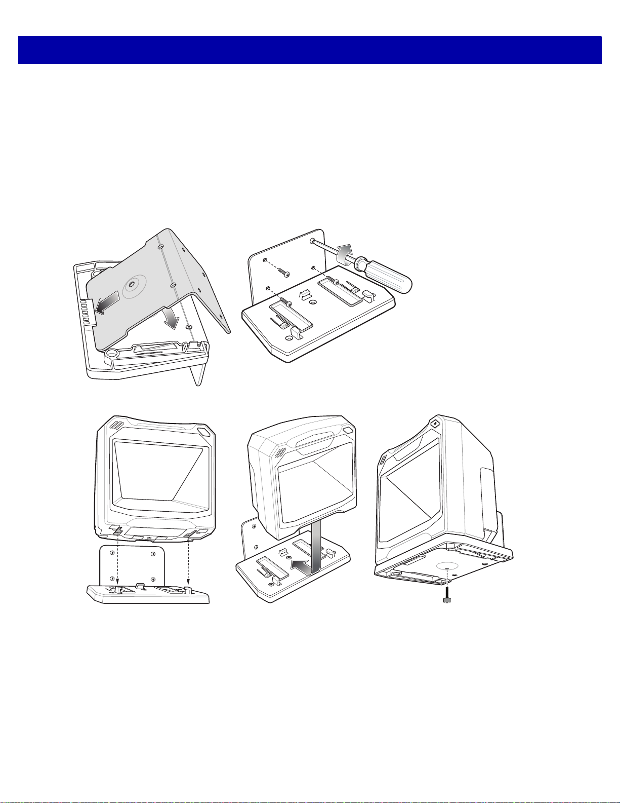
GETTING STARTED 1 - 9
2
1
4
5
3
1. See Removing and Repla cing the Back Cover on page 1-5 to connect all interface and power cables to the
scanner. Ensure the back cover is replaced and the cables are routed appropriately.
2. Determine the location for installing the scanner.
3. Figure 1-10 - 1: Mount the table bracket with three screws (not included).
4. Figure 1-10 - 2: Invert the scanner slightly and align the mounting slo ts over the plastic tabs on the bracket.
5. Figure 1-10 - 3: Insert the plastic tabs into the mounting slots on the scanner, and slide the scanner back
until it clicks into place.
Mounting the Scanner to a Wall
Figure 1-11 Wall Mounting Diagram - Mounting the Bracket
Figure 1-12 Wall Mounting Diagram - Mounting the Scanner on Bracket
1. Follow the steps in Removing and Replacing the Back Cover on page 1-5 to connect all interface and
power cables to the scanner. Ensure the back cover is replaced and the cables are routed appropriately.
2. Determine the location for installing the scanner.
3. Use the Wall Mount Template on page 1-12 as a guide to mark the four mounting holes.
4. Figure 1-11 - 1: Insert the back metal bracket under the plastic hook in the base plate and set in place so
that the thumb screw holes align.
5. Place the mounting bracket in position over the drilled holes with its flat surface facing the mounting
surface.
Page 34

1 - 10 DS7708 2D Vertical Slot Scanner Product Reference Guide
6. Figure 1-11 - 2: Insert four screws (provided) through the holes and fasten to the mounting surface.
7. Figure 1-12 - 3: Invert the scanner slightly and align the mounting slo ts over the plastic tabs on the bracket.
8. Figure 1-12 - 4: Insert the plastic tabs into the mounting slots on the scanner, and slide the scanner back
until it clicks into place.
9. Figure 1-12 - 5: To secure the scanner in the bracket, insert the thumb screw ( provided) through the hole in
the bottom of the bracket and fasten to the scanner bottom.
Removing the Scanner from the Mounting Bracket
To remove the scanner:
1. Grasp the scanner firmly on both sides.
2. Slide the scanner forward and lift out.
Page 35

Operating the Scanner
Indicator Lights
The scanner includes an array of three bi-color (green/red) LEDs to display system status and alerts. Center
LED conditions: Off, Dim, Full; Outer LED conditions: Off, Full.
Adjusting Speaker Volume
To change the volume of the beep, scan the a bar code in the section Beeper V olum e on page 5 -11, or use the
two-function Volume/Tone button on the front of the scanner (see Figure 1-2 on page 1-2).
Press and release the Volume/Tone button repeatedly until the desired volume level sounds (high, medium or
low).
Adjusting Speaker Tone
To change the tone of the beep, scan the a bar code in the section Beeper Tone on page 5-8, or use the
two-function Volume/Tone button on the front of the scanner (see Figure 1-2 on page 1-2).
Press and hold the Volume/Tone button for three seconds to change to a different tone. Repeat this process
until the desired tone sounds (high, medium, low or medium to high tone).
GETTING STARTED 1 - 11
Note If the decode tone is set to Off, the Volume/Tone button cannot be used to change the decode tone. To allow
the tone change using the Volume/Tone button, scan a tone other than Off.
If the Volume/Tone Button Control parameter is set to Disable Volume and Tone Change, the
Volume/Tone button on the scanner cannot be used to cha nge the volume and tone of the beeps.
Page 36
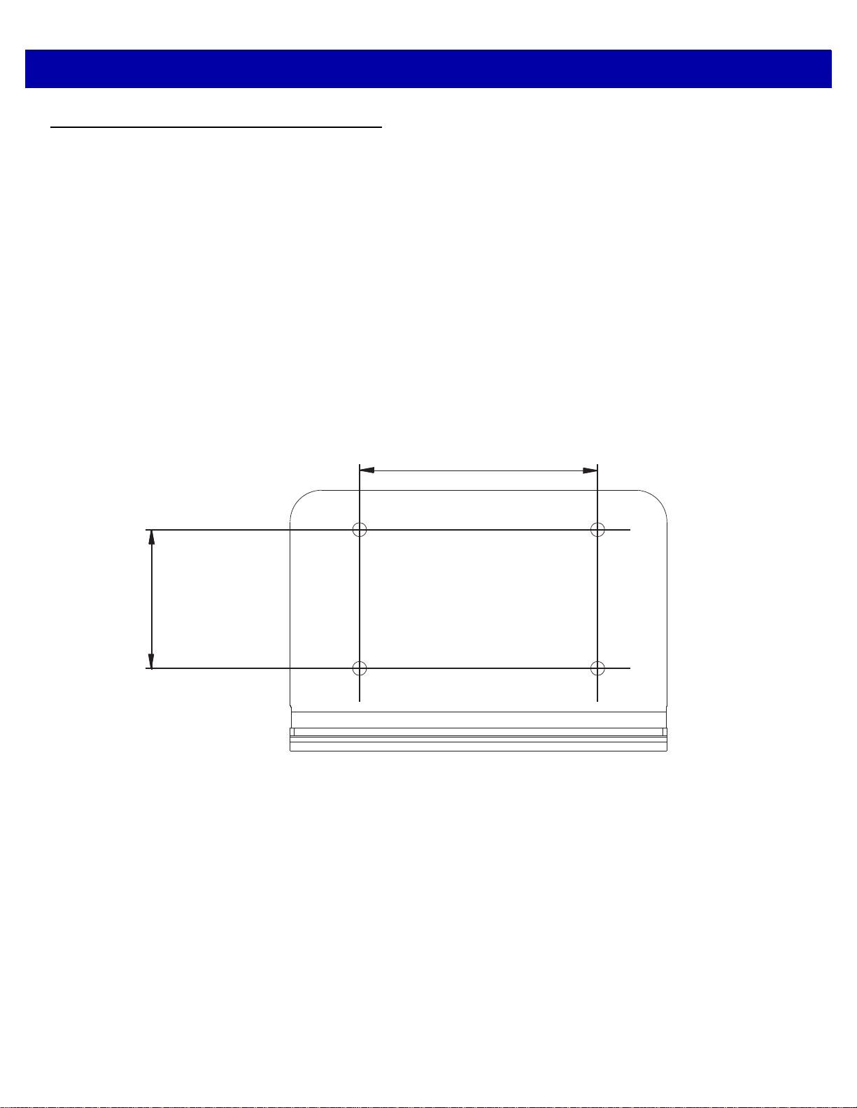
1 - 12 DS7708 2D Vertical Slot Scanner Product Reference Guide
2.36 in. (60.00 mm)
1.38 in. (35.00 mm)
Wall Mount Template
To use this template:
1. Print the actual size of this page. Do not scale.
2. Determine the location for installing the scanner.
3. Tape the template to the wall.
4. Drill the four holes using the template.
5. Place the mounting bracket in position over the drilled holes with its flat surface facing the mounting
surface.
6. Insert four screws (provided) through the holes and fasten to the mounting surface.
Figure 1-13 Wall Mount Template
Page 37

Table Mount Template
The recommended method of installation is attaching the scanner to the table top using the double-sided tape
provided on the bottom of the bracket. If you wish to mount the bracket to the table top with screws use the
template provided in
To use this template:
1. Print the actual size of this page. Do not scale.
2. Determine the location for installing the scanner.
3. Tape the template to the table.
4. Drill the three holes using the template.
5. Place the mounting bracket in position over the drilled holes with the Symbol logo facing up.
6. Insert three screws (not provided) through the holes and fasten to the table surface.
Figure 1-14.
GETTING STARTED 1 - 13
Figure 1-14 Table Mount Template
2.16 in. (54.88 mm)
4.26 in. (108.20 mm)
Page 38

1 - 14 DS7708 2D Vertical Slot Scanner Product Reference Guide
Page 39

CHAPTER 2 123SCAN
Introduction
123Scan is a software tool that simplifies scanner setup and more.
Intuitive enough for first time users, the 123Scan wizard guides users through a streamlined setup process.
Settings are saved in a configuration file that can be printed as a single programming bar code for scanning,
emailed to a smart phone for scanning from its screen, or downloaded to the scanner using a USB cable.
Through 123Scan a user can:
•
Configure a scanner using a wizard
• Program the following scanner settings:
• Beeper tone / volume settings
• Enable / disable symbologies
• Communication settings
• Preferred Symbol
• Modify data before transmission to a host using:
• Advanced Data Formatting (ADF) - Scan one bar code per trigger pull
• Multicode Data Formatting (MDF) - Scan many bar codes in one trigger pull
•
Load parameter settings to a scanner via:
• Bar code scanning:
• Scan a paper bar code
• Scan a bar code from a PC screen
• Scan a bar code from a smart phone screen
• Download over a USB cable:
• Load settings to one scanner
• Stage up to 10 scanners simultaneously
Page 40

2 - 2 DS7708 2D Vertical Slot Scanner Product Reference Guide
•
Validate scanner setup:
• View scanned data within the utility's Data View screen
• Capture an image and save to a PC within the utility's Data View screen
• Review settings using the Parameter Report
• Clone settings from an already deployed scanner
•
Upgrade scanner firmware:
• Load settings to one scanner
• Stage up to 10 scanners simultaneously with a power USB hub
•
View statistics such as:
• Asset tracking information
• Time and usage information
• Bar codes scanned by symbology
• Battery diagnostics
• Communication diagnostics
•
Generate the following reports:
• Barcode Report - Programming bar code, included parameter settings, and supported scanner
models
• Parameter Report - Lists parameters programmed within a configuration file
• Activity Report - Lists activities performed on a scanner(s)
• Inventory Report - Lists scanner asset tracking information
• Validation Report - Printout of scanned data
• Statistics Report - Lists all statistics retrieved from the scanner
For more information go to: zebra.com/123Scan.
Communication with 123Scan
Use a USB cable to connect the scanner to a Windows host computer r unning 123Scan.
123Scan Requirements
•
Host computer running Windows
•
Scanner
•
USB cable.
Page 41

123Scan Information
For more information on123Scan, go to: zebra.com/123Scan
For a 1 minute tour of 123Scan, go to: zebra.com/ScannerHowToVideos
To download any of the following free tools, go to: zebra.com/scannersoftware
•
123Scan configuration utility (described in this chapter)
•
How-to-videos.
Scanner SDK, Other Software Tools, and Videos
Tackle all your scanner programming needs with our diversified set of software tools. Whether you need to
simply stage a device, or develop a fully featured application with image and data capture as well as asset
management, these tools help you every step of the way.
To download any of the following free tools, go to: zebra.com/scannersoftware.
•
123Scan configuration utility
123SCAN2 - 3
•
SDKs
• Scanner SDK for Windows
• Scanner SDK for Linux
•
Drivers
• OPOS driver
• JPOS driver
• TWAIN driver
• USB CDC driver
•
Scanner Management Service (SMS) for Remote Management
• Windows
• Linux
• IBM 4690
•
How-To-Videos
•
User documentation.
Page 42

2 - 4 DS7708 2D Vertical Slot Scanner Product Reference Guide
Page 43

CHAPTER 3 DATA CAPTURE
Overview
This chapter covers the techniques involved in scanning bar codes, beeper and LED definitions, and general
instructions and tips about scanning. See
components. See each host chapter for information about connecting host cable s and power supplies, when
necessary.
Chapter 1, GETTING STARTED for information on scanner
Page 44

3 - 2 DS7708 2D Vertical Slot Scanner Product Reference Guide
To scan a bar code:
1. Ensure all cable connections are secure.
2. Orient the item with the bar code facing the
scanner window.
3. Present the item anywhere within the active scan
area.
4. Upon successful decode, the scanner beeps and
the green LED flashes momentarily.
Scanning Bar Codes on Products
Install and program the scanner.
For the best scanning performance, the table top or surface area covered by the active scan area should be
free of any designs (for example, stripes or patterns). Ideally, that area should be a light, solid color.
The DS7708 includes an automatic Object Detection wakeup system that provides a high swipe speed and
reduces power consumption. The red Illumination has two power levels mode: Idle Mode for object detection
and Full Illumination for scanning. When any object is presented in front of the window opening, the red
illumination changes from Idle Mode to Full Mode, but automatically returns to Idle Mode when the object is
removed. When the object presented in the Field of View (F OV) includes a bar code, the DS7708 scans the
bar code, and if the bar code is successfully decoded, the illumination LEDs automatically return to Idle Mode
when the object is removed.
The DS7708 is able to adjust the FOV by a reading a command bar code and pr event decodin g undesired ba r
codes that are in the FOV.
Active Scan Area
The active scan area is the area in front of the scanner window opening in which a bar code can be decoded.
The dotted area represents the active scan area.
Figure 3-1 Active Scan Area
Page 45

Decode Ranges
Table 3-1 includes the paper bar code decode ranges for the scanner.
Table 3-1 Decode Ranges
Symbol Specifications Typical Ranges (Inches)
Code 39, 5mil 0 - 7.20
UPCA, 10.0mil (80%) 0 - 10.0
UPCA, 13.0mil (100%) 0 - 10.3
PDF417, 4mil 0 - 2.20
PDF417, 5mil 0 - 3.50
PDF417, 6.6mil 0 - 5.20
PDF417, 10 mil 0 - 7.30
DATA CAPTURE 3 - 3
PDF417, 15 mil 0 - 9.90
Data Matrix, 10mil 0 - 5.00
Data Matrix, 20mil 0 - 9.50
QR cell phone 23mil 0 - 7.0
Page 46

3 - 4 DS7708 2D Vertical Slot Scanner Product Reference Guide
User Indicators
Table 3-2 lists beeper and LED indicators.
Beeper Volume/ Beeper Tone
If the decode tone is set to Off, the Volume/Tone button cannot be used to change the decode tone. To allow
the tone change using the Volume/Tone button, scan a tone other than Off.
See Adjusting Speaker Volume on page 1-11 and Adjusting Sp eaker Tone on page 1-1 1 to change the volume
and/or tone of the beep.
LED and Beeper Indicators
The scanner includes an array of three bi-color (green/red) LEDs to display system status and alerts.
Center LED conditions: Off, Full; Outer LED conditions: Off, Full.
Table 3-2 Beeper and LED Indicators
Event Beeper Sequence LED Description
Standard Use
Bootup Low, medium, high
beeps
Decode (as configured) Center green full on,
Presentation Mode None Center green LED
Transmi t Error 4 low beeps Red Transmission error
Convert Error 5 low beeps Red Conversion or Format error
Parity Error Low, low, low, extra
low beeps
BELL (RS-232) High beep None A <BEL> character is received
Image Capture
Snapshot Start Low beep All green, blinking Snapshot mode started.
Snapshot Complete Low beep Green (default) LED
Green Power up.
A bar code symbol was decoded.
followed by outer LEDs
green full on
Presentation Mode is on.
remains ON
Red RS-232 Receive error
over RS-232
Snapshot mode completed.
mode based upon
Hands-free mode state
Snapshot Timeout High, low beeps Green (default) LED
mode based upon
Hand-held/Hands-free
mode state
Parameter Programming
Unless otherwise specified, both red and green LEDs display across all three LED indicators (center and outer).
Snapshot mode timed-out.
Page 47

DATA CAPTURE 3 - 5
Table 3-2 Beeper and LED Indicators (Continued)
Event Beeper Sequence LED Description
Entry Error Low, high beeps Red Input error: incorrect bar code,
programming sequence, or
Cancel
scanned.
Number Expected High, low beeps Green Number expected. Enter value
using numeric bar codes.
Parameter Entered High, low, high, low
beeps
Green Successful program exit with
change in parameter setting.
ADF Programming
(Refer to the Advanced Data Formatting Programmer Guide, p/n 72E-69680-xx. for ADF bar codes.)
Number Expected High, low beeps Green Enter another digit. Add leading
zeros to the front if necessary.
Alpha Expected Low, low beeps Green Enter another alphabetic
character or scan the
Message
bar code.
End of
Criteria Action Expected High, high beeps Green blinking ADF criteria or action is
expected. Enter another criterion
or action, or scan the
Save Rule
bar code.
Rule Saved High, low, high, low
beeps
Green (turns off blinking) Rule saved. Rule entry mode
exited.
Criteria Action Cleared High, low, low beeps Green All criteria or actions cleared for
current rule. Continue entering
rule.
Last Rule Deleted Low beep Green Delete last saved rule. The
current rule is left in tact.
All Rules Deleted Low, high, high beeps Green All rules are deleted.
Out Of Rule Memory Low, high, low, high
beeps
Red Out of rule memory. Erase some
existing rules, then try to save
rule again.
Cancel Rule Entry Low, high, low beeps Green (turns off blinking) Cancel rule entry. Rule entry
mode exited because of an error,
or the user asked to exit rule
entry.
Rule Error Low, high beeps Red Entry error, wrong bar code
scanned, or criteria/action list is
too long for a rule. Re-enter
criterion or action.
Macro PDF
Unless otherwise specified, both red and green LEDs display across all three LED indicators (center and outer).
Page 48

3 - 6 DS7708 2D Vertical Slot Scanner Product Reference Guide
Table 3-2 Beeper and LED Indicators (Continued)
Event Beeper Sequence LED Description
Macro PDF Buffered 2 Low beeps None File ID error. A bar code not in
the current Macro PDF sequence
was scanned.
Macro PDF File ID Error 2 Long low beeps None File ID error. A bar code not in
the current Macro PDF sequence
was scanned.
Macro PDF Out Of Memory 3 Long low beeps None Out of memory. There is not
enough buffer space to store the
current Macro PDF symbol .
Macro PDF Bad Symbology 4 Long low beeps None Bad symbology. Scanned a 1D or
2D bar code in a Macro PDF
sequence, a duplicate Macro
PDF label, a label in an incorrect
order, or trying to transmit an
empty or illegal Macro PDF field.
Macro PDF Flush Buffer 5 Long low beeps None Flushing Macro PDF buffer.
Macro PDF Abort Fast warble beep None Aborting Macro PDF sequence.
Macro PDF Flush No Data Low, high beeps None Flushing an already empty Macro
PDF buffer.
Unless otherwise specified, both red and green LEDs display across all three LED indicators (center and outer).
Page 49

Electronic Article Surveillance (EAS)
The scanner includes an integrated Electronic Article Surveillance (EAS) antenna. The scanner and EAS
system can operate independently of each other. The deactivation range is mapped suitable to the scanning
range, so both can be accomplished almost simultaneously.
A pair of EAS leads in th e back of the DS7708 allow the EAS deactivation antenna to be connected to the
Checkpoint EAS system at the other end.
Installing
Checkpoint EAS Model Compatibility
The DS7708 is intended for use with Checkpoint CP-VII, CP-IX, and CP-XI systems. It does n ot support CP- IV
and other low-power receiver-based EAS deactivation systems.
Considerations
The Checkpoint CP-VII system generates a periodic burst of electromagnetic energy that de activates EAS tags
brought near the scanner. To avoid interference with the scanner’s operation, take the following precautions
when installing the EAS system:
DATA CAPTURE 3 - 7
•
Position the EAS antenna box as far as possible from the scanner (at least 6 in. / 15.24 cm.)
•
Position the EAS antenna, EAS antenna box, EAS control cable, and EAS controller box as far as
possible from the scanner’s host and power cables.
EAS range is as dependent on the Checkpoint system (which is calibrated onsite) as it is on the scanner.
Therefore, we cannot provide estimated ranges, however these a re some of th e factor s that cont ribute to EAS
range:
•
Antenna – Length, gauge, number of turns, placement in the scanner
•
Type of Checkpoint EAS system used (ie. CP-VII, CP-IX, and CP-XI)
•
Length of wire connecting antenna to (Checkpoint) EAS (site/installation dependent)
•
Settings done within Checkpoint system (site/installation dependent).
Checkpoint Contact Information
Contact your local Checkpoint representative to install the EAS cable to the Checkpoint Deactivation System.
Page 50

3 - 8 DS7708 2D Vertical Slot Scanner Product Reference Guide
Page 51

CHAPTER 4 MAINTENANCE, TECHNICAL
SPECIFICATIONS, MOUNTING
TEMPLATES
Introduction
This chapter covers suggested scanner maintenance, troubleshooting, technical specifications, and signal
descriptions (pinouts).
Maintenance
Cleaning the exit window is the only maintenance required. A dirty window can affect scanning accuracy.
•
Do not allow abrasive material to touch the window.
•
Remove dirt particles with a damp cloth.
•
Wipe the window using a tissue moistened with ammonia/water.
•
Do not spray water or other cleaning liquids directly into the window.
Page 52

4 - 2 DS7708 2D Vertical Slot Scanner Product Reference Guide
Troubleshooting
Note If after performing the checks in Table 4-1 the problem persists, contact the distributor or call the Zebra
Support Center. See Service Information on page x for more information.
Table 4-1 Troubleshooting
Problem Possible Causes Possible Solutions
The red LED illumination does not
come on when the directions for
installing the host cable are followed.
The red LED illumination gets brighter
when the bar code is presented in the
field of view, but bar code cannot be
read.
The red LED illumination turns on dim
and does not get brighter (the scanner
does not change to active decoding
mode) when a bar code is presented in
the field of view.
No power to the scanner. Ensure the host has power, and is
on. If the scanner uses a separate
power supply , ensure it is c onnected
to a working AC outlet.
Power-up sequence is incorrect.
Refer to the Product Reference
Guide for more information.
Interface cable is not properly
connected.
Scanner is not programmed
to read the bar code type.
Bar code is damaged. Try scanning other bar codes of the
Bar code is not within the
scanner's decode range.
The host has disabled
scanning or overridden
parameter settings.
Bar code is not within the
scanner's detection range.
Check for loose cable connections.
Ensure scanner is programmed to
read the bar code type scanned.
same bar code type.
Move the bar code to the region
within the scanner's decode range.
See the technical person in charge
of scanning.
Move the bar code to the region
within the scanner’s detection
range.
Page 53

MAINTENANCE, TECHNICAL SPECIFICATIONS, MOUNTING TEMPLATES 4 - 3
Table 4-1 Troubleshooting (Continued)
Problem Possible Causes Possible Solutions
Bar code is decoded, but not
transmitted to the host.
Scanned data is incorrectly displayed
on the host.
USB host not functioning properly. Scanner does not recognize
Scanner is not programmed
for the correct host type.
Scanner is not programmed
to work with the host. Check
scanner host type parameters
or editing options.
host.
Scan the appropriate host type bar
code.
Ensure proper host is selected.
For RS-232, ensure the scanner’s
communication parameters match
the host’s settings.
For Keyboard Wedge, ensure
scanner is programmed with the
correct country code and that the
CAPS LOCK key is off.
Ensure editing options (for
example., UPCE to UPCA
Conversion) are properly
programmed.
Remove and reinsert the USB cable
and the external power supply, if
applicable.
Page 54

4 - 4 DS7708 2D Vertical Slot Scanner Product Reference Guide
Technical Specifications
Table 4-2 Technical Specifications
Item Description
Physical Characteristi cs
Dimensions Scanner only
5.63 in. H x 5.86 in. W x 3.81 in. D
14.3 cm H x 14.9 cm W x 9.7 cm D
Scanner with Table Mount Kit
6.06 in. H x 5.93 in. W x 3.85 in. D
15.4 cm H x 15.1 cm W x 9.8 cm D
Weight 17.6 oz. / 500 g
Voltage and Current Without auxiliary scanner
Standby: 5 VDC +/-10% @ 125ma average
Operating: 5 VDC +/-10% @ 480ma average
With auxiliary scanner
Standby: 12 VDC +/-10% @ 100ma average
Operating: 12 VDC +/-10% @ 400ma average
Color Midnight Black
Host Interfaces USB, RS-232, Keyboard Wedge, TGCS (IBM) 46XX over RS485
Keyboard Support Over 90 international keyboards
Auxiliary Scanner Interface USB
Electronic Article Surveillance Compatible with Checkpoint EAS deactivation systems
User Feedback Speaker (Adjustable Tone & Volume), Good Decode LEDs
Performance Characteristics
Swipe Speed Up to 100 in/sec (254 cm/sec) for 13 mil UPC in out-of box mode
Light Source Two deep red LEDs (660nm)
Imager Field of View 48.0°x 36.7° (bar-code reading), 48.0°x 33.7° (image capture)
Image Sensor Global shutter 1280x 960 (bar-code reading), 1280x 880 (image
capture)
Minimum Print Contrast 25% minimum reflective difference
Roll / Pitch / Yaw (Skew) 360˚, ±70˚, ±70˚ typical with Code 39 20mil bar code at 3 inches
Imaging Characteristics
Graphics Format Support Images can be exported as Bitmap, JPEG or TIFF
Page 55

MAINTENANCE, TECHNICAL SPECIFICATIONS, MOUNTING TEMPLATES 4 - 5
Table 4-2 Technical Specifications (Continued)
Item Description
Image Transfer Speed USB 2.0: Up to 12 Megabits/second
RS-232: Up to 115 kb/second
Image Transfer Time Typical USB application is ~0.25 seconds with a compressed JPEG of
100kb
Image Quality 210 PPI (Minimum Font Size resolution: 7) on a 4 x 6 in. (10.2 x 15.2 cm)
document @ 3.0 in. (7.62 cm)
User Environment
Operating Temperature 32˚ to 104˚ F / 0˚ to 40˚ C
Storage Temperature -40˚ to 158˚ F / -40˚ to 70˚ C
Humidity 5% to 85% RH, non-condensing
Environmental Sealing: IP52
Electrostatic Discharge (ESD) ESD per EN61000-4-2, +/- 25 KV Air Direct, +/- 8 KV Indirect (without
auxiliary scanner)
Ambient Light Range From darkness (0 fcd) to 450 fcd artificial light and 10000 fcd direct
sunlight
Utilities and Management
123Scan2, Scanner Management Services (SMS), Symbol Scanner SDK
Accessories
Hands-Free Options Table Mount Bracket (Midnight Black)
Wall Mount Bracket (Midnight Black)
Power Supplies Power supplies are available for applications that do not supply power
over the host cable or utilize an auxiliary scanner.
Symbology Decode Capability
1D UPC/EAN (UPCA/UPCE/UPCE1/EAN-8/EAN-13/JAN-8/JAN-13 plus
supplementals, ISBN (Bookland), ISSN, Coupon Code), Code 39
(Standard, Full ASCII, Trioptic, Code 32 (Italian Pharmacode)), Code
128 (Standard, Full ASCII, UCC/EAN-128, ISBT-128 Concatenated),
Code 93, Codabar/NW7, 2 of 5 (Interleaved 2 of 5, Discrete 2 of 5, IATA,
Chinese 2 of 5, Matrix 2 of 5, Code 11), MSI Plessey, GS1 DataBar
(Omnidirectional, T runcated, Stacked, Stacked Omnidirectional, Limited,
Expanded, Expanded Stacked)
Page 56

4 - 6 DS7708 2D Vertical Slot Scanner Product Reference Guide
Table 4-2 Technical Specifications (Continued)
Item Description
2D PDF417 (Standard, Macro), MicroPDF417 (Standard, Macro),
Composite Codes (CC-A, CC-B, CC-C), TLC-39, Aztec (Standard,
Inverse), MaxiCode, DataMatrix/ECC 200 (Standard, Inverse, GS1), QR
Code (Standard, Inverse, Micro, GS1), Chinese Sensible (Han Xin)
Postal U.S. Postnet and Planet, U.K. Post, Japan Post, Australian Post,
Netherlands KIX Code, Royal Mail 4 State Customer, UPU FICS 4 State
Postal, USPS 4CB
Minimum Element Resolution Code 39 – 3 mil
UPC – 7.8 mil (60%), there is no higher density UPC bar code
PDF417 – 4 mil
Datamatrix – 7.5 mil
QR Code – 7.5 mil
Page 57
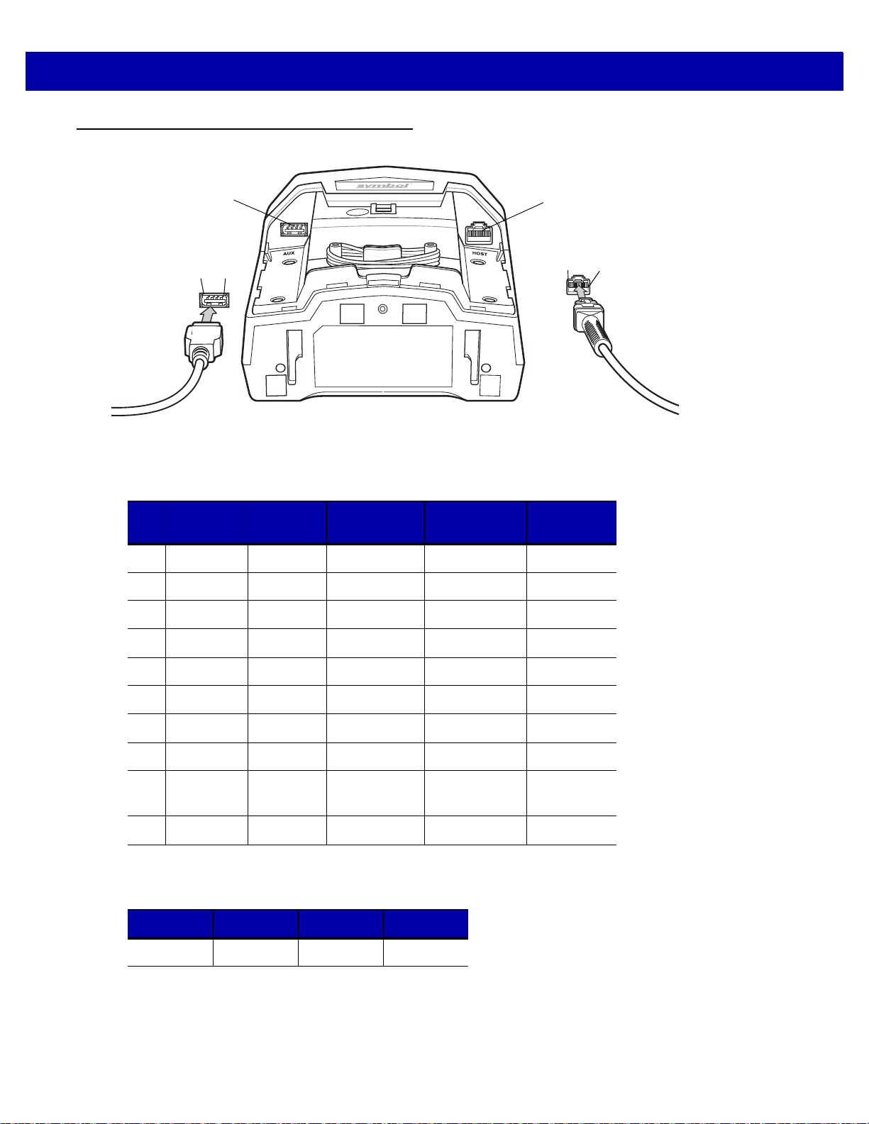
MAINTENANCE, TECHNICAL SPECIFICATIONS, MOUNTING TEMPLATES 4 - 7
Pin
4
Pin
1
Host Port
USB Auxiliary
Scanner Port
Pin
10
Pin
1
Scanner Signal Descriptions
Figure 4-1 Cable Pinouts
The signal descriptions in Table 4-3 apply to the connectors on the scanner and are for reference only.
Table 4-3 Scanner/Host Signal Pin-outs
Pin IBM RS-232
1 Reserved Reserved Reserved Jump to Pin 6 Reserved
2 +5v +5v +5v +5v +5v
3 Ground Ground Ground Ground Ground
4 IBM_A(+) TxD KeyClock Reserved TxD
5 Reserved RxD TermData D + Reserved
6 IBM_B(-) RTS KeyData Jump to Pin 1 RxD
7 Reserved CTS TermClock D - Reserved
8 Reserved Reserved Reserved Reserved Reserved
9 Passive
10 +12v +12v +12v +12v Reserved
Table 4-4 USB Auxiliary Scanner Port Pinouts
Keyboard
Wedge
Detect
Passive
Detect
Passive
Detect
Pin 1 Pin 2 Pin 3 Pin 4
USB Download
Passive
Detect
Reserved
VCC D- D+ GND
Page 58

4 - 8 DS7708 2D Vertical Slot Scanner Product Reference Guide
Page 59

CHAPTER 5 USER PREFERENCES &
*High Volume
(00h)
Feature/Option
* Indicates Default
Option Hex Value
MISCELLANEOUS OPTIONS
Introduction
You can program the scanner to perform various functi ons, or activate different features. This chapter
describes each user preference feature and provides programming bar codes for selecting th es e fea tu re s.
The scanner ships with the settings shown in Table 5-1 on page 5-2 (also see Appendix A, STANDARD
DEFAULT PARAMETERS for all host device and miscellaneous defaults). If the default values suit
requirements, programming is not necessary.
To set feature values, scan a single bar code or a short bar code sequence. The settings are stored in
non-volatile memory and are preserved even when the scanner is powered down.
If not using a USB cable, select a host type (see each host chapter for specific host information) after the
power-up beeps sound. This is only necessary upon the first power-up when connected to a new host.
To return all features to default values, scan the Set Default Parameter on page 5-4. Throughout the
programming bar code menus, asterisks indicate (*) default values.
Page 60

5 - 2 DS7708 2D Vertical Slot Scanner Product Reference Guide
Scanning Sequence Examples
In most cases, scanning one bar code sets the parameter value. For example, to set the beeper tone to high,
scan the High Tone (beeper tone) bar code in the Beeper Tone section on
page 5-8. Other parameters, such
as Serial Response Timeout or Data Transmis sion Formats, require scanning several bar codes. See the se
parameter descriptions for this procedure.
Errors While Scanning
Unless otherwise specified, to correct an error during a scanning sequence, just re-scan the correct parameter.
User Preferences/Miscellaneous Options Parameter Defaults
Table 5-1 lists defaults for user preferences parameters. To change the default values, scan the appropriate
bar codes in this guide. These new va lues r ep lace th e standar d d efault values in memor y. To recall the default
parameter values, scan the
Note See Appendix A, STANDARD DEFAUL T PARAMETERS for all user preferences, hosts, symbologies, and
miscellaneous default parameters.
Set Default Parameter on page 5-4.
Table 5-1 User Preferences Parameter Defaults
Parameter
Parameter SSI Number
1
Number
2
Default
User Preferences
Set Default Parameter N/A N/A Set Defaults
Parameter Bar Code Scanning ECh 236 Enable
Beep After Good Decode 38h 56 Enable
Beeper Tone 91h 145 High
Beeper Volume 8Ch 140 High
Beeper Duration F1h 74h 628 Medium
Volume/Tone Button Control F8h 05h 07h 1287 Enable (both)
Suppress Power-up Beeps F1h D1h 721 Do not suppress
Timeout Between Decodes, Same Symbol 89h 137 0.5 Sec
Timeout Between Decodes, Different Symbols 90h 144 1 Sec
Fuzzy 1D Processing F1h 02h 514 Enable
Decode Mirror Images (Data Matrix Only) F1h 19h 537 Auto
Page
Number
5-4
5-6
5-7
5-8
5-11
5-13
5-15
5-17
5-18
5-18
5-19
5-20
PDF Prioritization F1h CFh 719 Disable
PDF Prioritization Timeout F1h D0h 720 200 ms
1
2
SSI number hex values are used for progr am m i n g via SSI commands.
Parameter number decimal values are used for programming via RSM comm ands.
5-22
5-23
Page 61

USER PREFERENCES & MISCELLANEOUS OPTIONS 5 - 3
Table 5-1 User Preferences Parameter Defaults (Continued)
Parameter
Parameter SSI Number
1
Number
2
Default
Mobile Phone/Display Mode F1h CCh 716 Enable
Field of View F1h 61h 609 Full Field of View
Product ID (PID) Type
F8h 05h 01h
1281 Host Type Unique
Miscellaneous Options
Transmit Code ID Character 2Dh 45 None
Prefix Value 63h, 69h 99, 105 7013 <CR><LF>
Suffix 1 Value
Suffix 2 Value
62h, 68h
64h, 6Ah
98, 104
100, 106
7013 <CR><LF>
Scan Data Transmission Format EBh 235 Data as is
FN1 Substitution Values 67h, 6Dh 103, 109 7013 <CR> <LF>
Unsolicited Heartbeat Interval F8h 04h 5Eh 1118 Disable
1
2
SSI number hex values are used for progr am m ing via SSI commands.
Parameter number decimal values are used for programming via RSM commands.
Page
Number
5-24
5-25
5-27
5-29
5-31
5-31
5-34
5-38
5-39
Page 62

5 - 4 DS7708 2D Vertical Slot Scanner Product Reference Guide
User Preferences
Set Default Parameter
You can reset the scanner to two types of defaults: factory defaults or custom defaults. Scan the appropriate
bar code below to reset the scanner to its default settings and/or set its current settings as custom defaults.
Options:
•
*Set Defaults: Scan this bar code to reset all default parameters as follows.
• If you previously set custom defaults by scanning Write to Custom Defaults, scan Set Defaults to
retrieve and restore the scanner custom default settings.
• If you did not set custom defaults, scan Set Defaults to restore the factory default values listed in
T able A-1.
•
Set Factory Defaults: Scan this bar code to restore the factory default values listed in Table A-1. This
deletes any custom defaults set.
•
Write to Custom Defaults: Scan this bar code to set the current scanner settings as custom defaults.
Once set, you can recover custom default settings by scanning Set Defaults.
*Set Defaults
Set Factory Defaults
Page 63

Set Default Parameter (continued)
USER PREFERENCES & MISCELLANEOUS OPTIONS 5 - 5
Write to Custom Defaults
Page 64

5 - 6 DS7708 2D Vertical Slot Scanner Product Reference Guide
Parameter Bar Code Scanning
SSI # ECh
Parameter # 236
To disable the decoding of parameter bar codes, including the Set Defaults parameter bar codes, scan the
Disable Parameter Scanning bar code below. To enable decoding of parameter bar codes, scan Enable
Parameter Scanning.
Options:
•
*Enable Parameter Bar Code Scanning
•
Disable Parameter Bar Code Scanning.
*Enable Parameter Bar Code Scanning
(01h)
Disable Parameter Bar Code Scanning
(00h)
Page 65

USER PREFERENCES & MISCELLANEOUS OPTIONS 5 - 7
Beep After Good Decode
SSI # 38h
Parameter # 56
Scan a bar code below to select whether or not the scanner beeps after a good decode. If selecting Do Not
Beep After Good Decode, the beeper still operates during parameter menu scanning and to indicate error
conditions.
Options:
•
*Beep After Good Decode ( Enable)
•
Do Not Beep After Good Decode (Disable).
*Beep After Good Decode
(Enable)
(01h)
Do Not Beep After Good Decode
(Disable)
(00h)
Page 66

5 - 8 DS7708 2D Vertical Slot Scanner Product Reference Guide
Beeper Tone
SSI # 91h
Parameter # 145
To select a decode beep frequency (tone), scan one of the bar codes that follow.
If the decode tone is set to Off, the Volume/Tone button cannot be used to change the decode tone. To allow
the tone change using the Volume/Tone button, scan a tone other than Off.
Options:
•
Off
•
Low Tone
•
Medium Tone
•
*High Tone
•
Medium to High Tone (2-tone).
Off
(03h)
Low Tone
(02
Page 67

Beeper Tone (continued)
USER PREFERENCES & MISCELLANEOUS OPTIONS 5 - 9
Medium Tone
(01h)
*High Tone
(00h)
Page 68

5 - 10 DS7708 2D Vertical Slot Scanner Product Reference Guide
Beeper Tone (continued)
Medium to High Tone (2-tone)
(04h)
Page 69

USER PREFERENCES & MISCELLANEOUS OPTIONS 5 - 11
Beeper Volume
SSI # 8Ch
Parameter # 140
To select a beeper volume, scan the one of the bar codes that follows.
Options:
•
Low Volume
•
Medium Volume
•
*High Volume
Low Volume
(02h)
Medium Volume
(01h)
Page 70

5 - 12 DS7708 2D Vertical Slot Scanner Product Reference Guide
Beeper Volume (continued)
*High Volume
(00h)
Page 71

USER PREFERENCES & MISCELLANEOUS OPTIONS 5 - 13
Beeper Duration
SSI # F1h 74h
Parameter # 628
To select the duration for the beeper, scan one of the following bar codes.
Options:
•
Short
•
*Medium
•
Long.
Short
(00h)
*Medium
(01h)
Page 72

5 - 14 DS7708 2D Vertical Slot Scanner Product Reference Guide
Beeper Duration (continued)
Long
(02h)
Page 73

USER PREFERENCES & MISCELLANEOUS OPTIONS 5 - 15
Volume/Tone Button Control
SSI # F8h 05h 07h
Parameter # 1287
When this parameter is enabled the physical Volume/Tone button on the front panel of the scanner can be
used to change the speaker volume and tone.
When this parameter is disabled the speaker volume and to ne cannot be changed using the physical
Volume/Tone button on the front panel of the scanner.
Options:
•
*Enable Volume and Tone Change
•
Disable Tone Change and Enable Volume Change
•
Enable Tone Change and Disable Volume Change
•
Disable Volume and Tone Change
*Enable Volume and Tone Change
(1)
Disable Volume and Tone Change
(0)
Page 74

5 - 16 DS7708 2D Vertical Slot Scanner Product Reference Guide
Volume/Tone Button Control (continued)
Disable Tone Change and Enable Volume Change
(2)
Enable Tone Change and Disable Volume Change
(3)
Page 75

USER PREFERENCES & MISCELLANEOUS OPTIONS 5 - 17
Suppress Power-up Beeps
SSI # F1h D1h
Parameter # 721
Select whether or not to suppress the scanner power-up beeps.
Options:
•
*Do Not Suppress Power-up Beeps
•
Suppress Power-up Beeps.
*Do Not Suppress Power-up Beeps
(00h)
Suppress Power-up Beeps
(01h)
Page 76

5 - 18 DS7708 2D Vertical Slot Scanner Product Reference Guide
Timeout Between Decodes, Same Symbol
SSI # 89h
Parameter # 137
Use this option to prevent the beeper from continuously beeping when a symbol is left in the scanner’s field of
view. It is programmable in 0.1 second increments from 0.0 to 9.9 seconds. The default interval is 0.5 seconds.
To select the timeout between decodes for the same symbol, scan the bar code below, then scan two numeric
bar codes from
increments.
Appendix G, NUMERIC BAR CODES that correspond to the desired interval, in 0.1 second
Timeout Between Decodes, Same Symbol
Timeout Between Decodes, Different Symbols
SSI # 90h
Parameter # 144
Use this option in to control the time the scanner is inactive between decoding different symbols. It is
programmable in 0.1 second increments from 0 to 9.9 seconds. The default is 1 second.
To select the timeout between decodes for different symbols, scan the bar code below, then scan two numeric
bar codes from
increments.
Appendix G, NUMERIC BAR CODES that correspond to the desired interval, in 0.1 second
Timeout Between Decodes, Different Symbols
Page 77

USER PREFERENCES & MISCELLANEOUS OPTIONS 5 - 19
Fuzzy 1D Processing
SSI # F1h 02h
Parameter # 514
This option is enabled by default to optimize decode performance on 1D bar codes, including damaged and
poor quality symbols. Disable this only if you experience time delays when decoding 2D bar codes, or in
detecting a no decode.
Options:
•
*Enable Fuzzy 1D Processing
•
Disable Fuzzy 1D Processing.
*Enable Fuzzy 1D Processing
(01h)
Disable Fuzzy 1D Processing
(00h)
Page 78

5 - 20 DS7708 2D Vertical Slot Scanner Product Reference Guide
Decode Mirror Images (Data Matrix Only)
SSI # F1h 19h
Parameter # 537
Select an option for decoding mirror image Data Matrix bar codes:
•
Always - decode only Data Matrix bar codes that are mirror images
•
Never - do not decode Data Matrix bar codes that are mirror images
•
Auto - decode both mirrored and unmirrored Data Matrix bar codes.
Never
(0)
Always
(1)
Page 79

USER PREFERENCES & MISCELLANEOUS OPTIONS 5 - 21
Decode Mirror Images (Data Matrix Only - continued)
*Auto
(2)
Page 80

5 - 22 DS7708 2D Vertical Slot Scanner Product Reference Guide
PDF Prioritization
SSI # F1h CFh
Parameter # 719
Enable this feature to delay decoding certain 1D bar codes (see Note below) by the value specified in PDF
Prioritization Timeout. During that time the scanner attempts to decode a PDF417 symbol (e.g., on a US
driver's license), and if successful, reports this only. If it does not decode (can not find) a PDF417 symbol, it
reports the 1D symbol after the timeout. The 1D sym bol must be in th e d evice’s field of view for the sca nner to
report it. This parameter does not affect decoding other symbologies.
Note
The 1D Code 128 bar code lengths include the following:
• 7 to 10 characters
• 14 to 22 characters
• 27 to 28 characters
In addition, a Code 39 bar code with the following lengths are considered to potentially be part of a US driver’s
license:
• 8 characters
• 12 characters
Options:
•
*Disable PDF Prioritization
•
Enable PDF Prioritization.
*Disable PDF Prioritization
(00h)
Enable PDF Prioritization
(01h)
Page 81

USER PREFERENCES & MISCELLANEOUS OPTIONS 5 - 23
PDF Prioritization Timeout
SSI # F1h D0h
Parameter # 720
When PDF Prioritization is enabled, this timeout specifies how long the scanner attempts to decode a PDF417
symbol before reporting the 1D bar code in the field of view.
Scan the following bar code, then scan four digits from Appendix G, NUMERIC BAR CODES that specify the
timeout in milliseconds. For example, to enter 400 ms, scan the following bar code, then scan 0400. The range
is 0 to 5000 ms, and the default is 200 ms.
PDF Prioritization Timeout
Page 82

5 - 24 DS7708 2D Vertical Slot Scanner Product Reference Guide
Mobile Phone/Display Mode
SSI # F1h CCh
Parameter # 716
This mode improves bar code reading performance off mo bile phones and elec tronic displays. Scan o ne of the
following bar codes to select the desired mode.
Options:
•
Normal Mobile Phone/Display Mode
•
*Enable Mobile Phone/Display Mode.
Normal Mobile Phone/Display Mode
(0)
*Enable Mobile Phone/Display Mode
(2)
Page 83

USER PREFERENCES & MISCELLANEOUS OPTIONS 5 - 25
Field of View
SSI # F1h 61h
Parameter # 609
By default, the scanner searches the full field of view.
To search for a bar code in a smaller region, in order to speed search time and prevent unintended bar code
reads, select Small Field of View or Medium Field of View.
Note When the scanner is set to Small Field of View or Medium Field of View and a bar code is only partially
presented into the field of view, the scanner automatically opens to Full Field of View to scan the bar
code. It then returns to the mode set.
Options:
•
Small Field of View
•
Medium Field of View
•
*Full Field of View.
Small Field of View
(00h)
Medium Field of View
(01h)
Page 84

5 - 26 DS7708 2D Vertical Slot Scanner Product Reference Guide
Field of View (continued)
*Full Field of View
(02h)
Page 85

Product ID (PID) Type
SSI # F8h 05h 01h
Parameter # 1281
Defines the PID value reported in USB enumeration.
Options:
•
*Host Type Unique
•
Product Unique
•
IBM Unique.
USER PREFERENCES & MISCELLANEOUS OPTIONS 5 - 27
*Host Type Unique
(0)
Product Unique
(1)
Page 86

5 - 28 DS7708 2D Vertical Slot Scanner Product Reference Guide
PID Type (continued)
IBM Unique
(2)
Page 87

Miscellaneous Scanner Parameters
Transmit Code ID Character
SSI # 2Dh
Parameter # 45
A Code ID character identifies the code type of a scanned bar code. This is useful when decoding more than
one code type. In addition to any single character prefix already selected, the Code ID character is inserted
between the prefix and the decoded symbol.
Select no Code ID character, a Symbol Code ID character, or an AIM Code ID character. For Code ID
Characters, see
Options:
•
Symbol Code ID Character
•
AIM Code ID Character
•
*None.
Symbol Code Identifiers on page E-1 and AIM Code Identifiers on page E-3.
USER PREFERENCES & MISCELLANEOUS OPTIONS 5 - 29
Symbol Code ID Character
(02h)
AIM Code ID Character
(01h)
Page 88

5 - 30 DS7708 2D Vertical Slot Scanner Product Reference Guide
Transmit Code ID Character (continued)
*None
(00h)
Page 89

USER PREFERENCES & MISCELLANEOUS OPTIONS 5 - 31
Prefix/Suffix Values
Key Category SSI # P = 63h, S1 = 62h, S2 = 64h
Decimal Value SSI # P = 69h, S1 = 68h, S2 = 6Ah
Key Category Parameter # P = 99, S1 = 98, S2 = 100
Decimal Value Parameter # P = 105, S1 = 104, S2 = 106
You can append a prefix and/or one or two suffixes to scan data for use in data editing. To set a value for a
prefix or suffix, scan a four-digit number (i.e., four bar codes from
corresponds to that value. See ASCII Character Set for USB on page 7-34 and ASCII Character Set for
RS-232 on page 8-37 for the four-digit codes.
When using host commands to set the prefix or suf fix, set the key category parameter to 1, then set the 3-digit
decimal value.
To correct an error or change a selection, scan Cancel on page G-10.
Note To use Prefix/Suffix values, first set the Scan Data Transmission Format on page 5-34.
Options:
Appendix G, NUMERIC BAR CODES) that
•
Scan Prefix
•
Scan Suffix 1
•
Scan Suffix 2
•
Data Format Cancel.
Scan Prefix
(07h)
Page 90

5 - 32 DS7708 2D Vertical Slot Scanner Product Reference Guide
Prefix/Suffix Values (continued)
Scan Suffix 1
(06h)
Page 91

Prefix/Suffix Values (continued)
USER PREFERENCES & MISCELLANEOUS OPTIONS 5 - 33
Scan Suffix 2
(08h)
Data Format Cancel
Page 92

5 - 34 DS7708 2D Vertical Slot Scanner Product Reference Guide
Scan Data Transmission Format
SSI # EBh
Parameter # 235
To set the scan data format, scan one of the following bar codes.
Note If using this parameter do not use ADF rules to set the prefix/suffix.
To set values for the prefix and/or suffix, see Prefix/Suffix Values on page 5-31.
Options:
•
*Data As Is
•
<DATA> <SUFFIX 1>
•
<DATA> <SUFFIX 2>
•
DATA> <SUFFIX 1> <SUFFIX 2>
•
<PREFIX> <DATA >
•
<PREFIX> <DATA> <SUFFIX 1>
•
<PREFIX> <DATA> <SUFFIX 2>
•
<PREFIX> <DATA> <SUFFIX 1> <SUFFIX 2>.
*Data As Is
(00h)
<DATA> <SUFFIX 1>
(01h)
Page 93

USER PREFERENCES & MISCELLANEOUS OPTIONS 5 - 35
Scan Data Transmission Format (continued)
<DATA> <SUFFIX 2>
(02h)
<DATA> <SUFFIX 1> <SUFFIX 2>
(03h)
Page 94

5 - 36 DS7708 2D Vertical Slot Scanner Product Reference Guide
Scan Data Transmission Format (continued)
<PREFIX> <DATA >
(04h)
<PREFIX> <DATA> <SUFFIX 1>
(05h)
Page 95

USER PREFERENCES & MISCELLANEOUS OPTIONS 5 - 37
Scan Data Transmission Format (continued)
<PREFIX> <DATA> <SUFFIX 2>
(06h)
<PREFIX> <DATA> <SUFFIX 1> <SUFFIX 2>
(07h)
Page 96

5 - 38 DS7708 2D Vertical Slot Scanner Product Reference Guide
FN1 Substitution Values
Key Category SSI # 67h
Decimal Value SSI # 6Dh
Key Category Parameter # 103
Decimal Value Parameter # 109
The wedge and USB HID keyboard hosts support a FN1 Substitution feature. Enabling this substitutes any
FN1 character (0x1b) in a GS1 bar code with a value. This value defaults to 7013 (En ter key).
When using host commands to set the FN1 substitution value, set the key category parameter to 1, then set
the 3-digit keystroke value. See the ASCII character set table for the current host interface for the desired
value.
To select a FN1 substitution value via bar code menus:
1. Scan the Set FN1 Substitution Value bar code below.
2. Locate the keystroke desired for FN1 substitution in the ASCII character set table in the appropriate host
interface chapter. Enter the 4-digit ASCII value by scanning each digit in Appendix G, NUMERIC BAR
CODES.
To correct an error or change the selection, scan Cancel on page G-10.
See USB Keyboard FN1 Substitution on page 7-17 to enable FN1 substitution for the USB HID keyboard.
Set FN1 Substitution Value
Page 97

USER PREFERENCES & MISCELLANEOUS OPTIONS 5 - 39
Unsolicited Heartbeat Interval
SSI # F8h 04h 5Eh
Parameter # 1118
The scanner supports sending Unsolicited Heartbeat Messag es to assist in diagn ostics. To enable this feature
and set the desired unsolicited heartbeat interval, scan one of the time interval bar codes below, or scan Set
Another Interval followed by four numeric bar codes from
sequential numbers that correspond to the desired number of seconds).
Options:
•
10 seconds
•
1 minute
•
Set Another Interval
•
*Disable Unsolicited Heartbeat Interval.
Scan Disable Unsolicited Heartbeat Interval to turn off the feature.
The heartbeat event is sent as decode data (with no decode beep) in the form of:
MOTEVTHB:nnn
where nnn is a three digit sequence number starting at 001 and wrapping after 100.
Appendix G, NUMERIC BAR CODES (scan
10 seconds
1 minute
Page 98

5 - 40 DS7708 2D Vertical Slot Scanner Product Reference Guide
Unsolicited Heartbeat Interval (continued)
Set Another Interval
*Disable Unsolicited Heartbeat Interval
Page 99

CHAPTER 6 IMAGING PREFERENCES
Feature/Option
* Indicates Default
*Full Resolution
(00h)
Option Hex Value
Introduction
You can program the scanner to perform various functi ons, or activate different features. This chapter
describes each user preference feature and provides programming bar codes for selecting th es e fea tu re s.
The scanner ships with the settings shown in Table 6-1 on page 6-2 (also see Appendix A, STANDARD
DEFAULT PARAMETERS for all host device and miscellaneous defaults). If the default values suit
requirements, programming is not necessary.
To set feature values, scan a single bar code or a short bar code sequence. The settings are stored in
non-volatile memory and are preserved even when the scanner is powered down.
If not using a USB cable, select a host type (see each host chapter for specific host information) after the
power-up beeps sound. This is only necessary upon the first power-up when connected to a new host.
To return all features to default values, scan the *Set Defaults on page 5-4. Throughout the programming bar
code menus, asterisks indicate (*) de fa ult valu es.
Page 100

6 - 2 DS7708 2D Vertical Slot Scanner Product Reference Guide
Scanning Sequence Examples
In most cases scanning one bar code sets the parameter value. For example, to enable signature capture,
scan the Enable Signature Capture bar code under
Signature Capture on page 6-20. The scanner issues a
fast warble beep and the LED turns green, signifying a successful parameter entry.
Other parameters require scanning several bar codes. See these parameter descriptions for this procedu re.
Errors While Scanning
Unless otherwise specified, to correct an error during a scanning sequence, just re-scan the correct parameter.
Imaging Preferences Parameter Defaults
Table 6-1 lists the defaults for imaging preferences parameters. To change the default values, scan the
appropriate bar codes in this guide. Th ese new values replace the stand ard default values in memory. To recall
the default parameter values, scan the
Note See Appendix A, STANDARD DEFAUL T PARAMETERS for all user preferences, hosts, symbologies, and
miscellaneous default parameters.
Set Default Parameter on page 5-4.
Table 6-1 Imaging Preferences Parameter Defaults
Parameter
Parameter SSI Number
1
Number
2
Default
Imaging Preferences
Operational Modes N/A N/A N/A
Snapshot Mode Timeout F0h 43h 323 0 (30 seconds)
Image Size (Number of Pixels) F0h 2Eh 302 Full
Image Brightness (Target White) F0h 86h 390 180
JPEG Image Options F0h 2Bh 299 Quality
JPEG Target File Size F1h 31h 561 160 kB
JPEG Quality and Size Value F0h 31h 305 65
Image Enhancement F1h 34h 564 Low (1)
Image File Format Selection F0h 30h 304 JPEG
Image Rotation F1h 99h 665 0
Bits per Pixel (BPP) F0h 2Fh 303 8 BPP
Signature Capture 5Dh 93 Disable
Page
Number
6-4
6-5
6-6
6-8
6-9
6-10
6-11
6-12
6-14
6-16
6-18
6-20
Signature Capture Image File Format
F0h 39h 313 JPEG
Selection
1
SSI number hex values are used for programming via SSI commands.
2
Parameter number decimal values are used for programming via RSM commands.
6-21
 Loading...