

Page 1
DS2278
MN-002915-06
Digital Scanner
Product Reference Guide
Page 2

Page 3

DS2278 DIGITAL SCANNER
PRODUCT REFERENCE GUIDE
MN-002915-06
Revision A
January 2020
Page 4

ii DS2278 Digital Scanner Product Reference Guide
No part of this publication may be reproduced or used in any form, or by any electrical or mechanical means,
without permission in writing from Zebra. This includes electronic or mechanical means, such as photo copying,
recording, or information storage and retrieval systems. The material in this manual is subject to change
without notice.
The software is provided strictly on an “as is” basis. All software, including firmware, furnished to the user is on
a licensed basis. Zebra grants to the user a non-transferable and non-exclusive license to use each software
or firmware program delivered hereunder (licensed program) . Except as n oted below, such license may not be
assigned, sub-licensed, or otherwise transferred by the user without prior written consent of Zebra. No right to
copy a licensed program in whole or in part is granted, except as permitted under copyright law. The user shall
not modify , merge, or incorporate any for m or portion of a licensed program with other pro gram material, create
a derivative work from a licensed program , or us e a li censed program in a network without written permission
from Zebra. The user agrees to maintain Zebra’s copyright notice on the licensed programs delivered
hereunder , and to include the same on any au thorized copies it m akes, in whole or in part. The user agrees not
to decompile, disassemble, decode, or reverse engineer any licensed program delivered to the user or any
portion thereof.
Zebra reserves the right to make changes to any software or product to improve reliability, function, or design.
Zebra does not assume any product liability arising out of, or in connection with, the application or use of any
product, circuit, or application described herein.
No license is granted, either expressly or by implication, estoppel, or otherwise under any Zebra Technologies
Corporation, intellectual property rights. An implied license only exists for equipment, circuits, and su bsystems
contained in Zebra products.
Warranty
For the complete Zebra hardware product warranty statement, go to: www.zebra.com/warranty.
Page 5

Revision History
Changes to the original guide are listed below:
Change Date Description
MN-002915-01 Rev. A 7/2017 Initial Release.
MN-002915-02 Rev. A 8/2017 Removed "Microsoft UWP Bluetooth" information.
MN-002915-03 Rev. A 04/2018 Rev. B software and miscellaneous updates.
iii
Added:
- Battery Preservation Timeout Value.
- Re-pair on Double Trigger Press.
- Note to Out of Range Batch Mode about Auto-Reconnect.
- Added note below Bluetooth Security.
Updated:
- Pairing bar code format with STC info.
- Values under bar codes for SSI baud rates: 230,400, 460,800,
921,600.
- Pairing Using the Scan-To-Connect (STC) Utility.
- Max time value in Hands-Free Decode Session Timeout.
- Deleted Bluetooth HID - Wait for Connection (not supported).
- Added note to MSI Reduced Quiet Zone (Level 3 not supported by
MSI).
- Changed Microsoft UWP USB to USB HID POS.
- Second paragraph under "Connection Maintenance Interval".
- 123Scan chapter
- Picklist Mode description.
- Trigger Mode, Presentation (Blink) de scription.
MN-002915-04 Rev. A 7/2018 Added:
- LED on Good Decode.
- Pairing Bar Code Format for Serial Port Connections.
- USB certification.
- Setting Up a Windows Product To Work With The Digital Scanner.
- New Appendix N - U
Updated:
- One instance of Class 1 to Class 2.
- Firmware download option (not supported with Micro USB cable).
- Configurations.
- "Connecting the Cradle" and "Changing the Host Interface".
MN-002915-05 Rev. A 10/2018 - Added Grid Matrix sample bar code.
- Moved 123Scan chapter.
MN-002915-06 Rev. A 01/2020 - Added ARINC param.
- Updated URLs.
- Updated Zebra copyright statement.
pgrading Over Bluetooth Without a Cradle.
Page 6

iv DS2278 Digital Scanner Product Reference Guide
Page 7

TABLE OF CONTENTS
Warranty ............................................................................................................................................ ii
Revision History................................................................................................................................. iii
About This Guide
Introduction...................................................................................................................................... xix
Configurations.................................................................................................................................. xix
Related Product Line Configurations............................................................................................... xx
Cables........................................................................................................................................ xx
Chapter Descriptions ....................................................................................................................... xx
Notational Conventions.................................................................................................................... xxi
Related Documents ........................................................................................................................ xxii
Service Information......................................................................................................................... xxii
Provide Documentation Feedback.................................................................................................. xxii
Chapter 1: Getting Started
Introduction .................................................................................................................................... 1-1
Interfaces ....................................................................................................................................... 1-2
Unpacking ...................................................................................................................................... 1-2
DS2278 Features ........................................................................................................................... 1-3
Cradle Features ............................................................................................................................. 1-3
Presentation Cradle ................................................................................................................. 1-4
Connecting the Cradle ............................................................................................................. 1-4
Changing the Host Interface .................................................................................................... 1-4
Using a DC Power Supply ........................................................................................................ 1-5
Charging the DS2278 Battery ........................................................................................................ 1-5
Charging Using the Cradle ....................................................................................................... 1-5
Charging Using the Micro USB Cable ...................................................................................... 1-6
Shutting Off the Digital Scanner Battery ........................................................................................ 1-7
Inserting the Battery ....................................................................................................................... 1-7
Removing the Battery .................................................................................................................... 1-8
Inserting the Digital Scanner in the Cradle .................................................................................... 1-9
Sending Data to the Host Computer .............................................................................................. 1-9
Pairing ...................................................................................................................................... 1-9
Page 8

vi DS2278 Digital Scanner Product Reference Guide
Lost Connection to Host ......................................................................................................... 1-10
Configuring the Digital Scanner ................................................................................................... 1-10
Radio Communications ................................................................................................................ 1-10
Accessories .................................................................................................................................. 1-10
Chapter 2: 123Scan and Software Tools
Introduction .................................................................................................................................... 2-1
123Scan ......................................................................................................................................... 2-1
Communication with 123Scan .................................................................................................. 2-2
123Scan Requirements .......................................................................................................... .. 2-2
123Scan Information ................................................................................................................ 2-2
Scanner SDK, Other Software Tools, and Videos ......................................................................... 2-3
Scanner Control App ...................................................................................................................... 2-4
Scan-To-Connect (STC) Utility ...................................................................................................... 2-4
Advanced Data Formatting (ADF) .................................................................................................. 2-4
Chapter 3: Data Capture
Introduction .................................................................................................................................... 3-1
Beeper and LED Indications .......................................................................................................... 3-1
Digital Scanner Indications ....................................................................................................... 3-1
Cradle LED Indications ............................................................................................................ 3-5
Scanning ........................................................................................................................................ 3-6
Hand-Held Scanning ................................................................................................................ 3-6
Hands-Free Scanning .............................................................................................................. 3-7
Aiming with Digital Scanner ..................................................................................................... 3-8
Aiming ...................................................................................................................................... 3-8
Decode Ranges ............................................................................................................................. 3-8
Chapter 4: Maintenance, Troubleshooting, & Technical Specifications
Introduction .................................................................................................................................... 4-1
Maintenance .................................................................................................................................. 4-1
Known Harmful Ingredients ...................................................................................................... 4-1
Approved Cleaners for the Digital Scanner and Cradle ........................................................... 4-2
Cleaning the Digital Scanner .................................................................................................... 4-2
Troubleshooting ............................................................................................................................. 4-3
Report Software Version Bar Code .......................................................................................... 4-7
Technical Specifications ................................................................................................................ 4-8
Cradle Signal Descriptions ........................................................................................................... 4-11
Chapter 5: User Preferences & Miscellaneous Options
Introduction .................................................................................................................................... 5-1
Setting Parameters ....................................................................................................................... 5-1
Scanning Sequence Examples ................................................................................................ 5-2
Errors While Scanning ............................................................................................................. 5-2
User Preferences/Miscellaneous Options Parameter Defaults ...................................................... 5-2
User Preferences ........................................................................................................................... 5-5
Default Parameters .................................................................................................................. 5-5
Parameter Bar Code Scanning ................................................................................................ 5-6
Page 9

Table of Contents vii
Beep After Good Decode ......................................................................................................... 5-6
Beeper Volume ........................................................................................................................ 5-7
Beeper Tone ............................................................................................................................ 5-8
Beeper Duration ....................................................................................................................... 5-9
Suppress Power Up Beeps ...................................................................................................... 5-9
LED on Good Decode ............................................................................................................ 5-10
Direct Decode Indicator .......................................................................................................... 5-10
Low Power Mode ................................................................................................................... 5-11
Time Delay to Low Power Mode ............................................................................................ 5-12
Timeout to Low Power Mode from Auto Aim .......................................................................... 5-14
Battery Preservation Mode ..................................................................................................... 5-15
Trigger Mode .......................................................................................................................... 5-16
Hands-Free Mode .................................................................................................................. 5-17
Hand-Held Decode Aiming Pattern ........................................................................................ 5-18
Hands-Free (Presentation) Decode Aiming Pattern ............................................................... 5-19
Picklist Mode .......................................................................................................................... 5-20
Continuous Bar Code Read ................................................................................................... 5-21
Unique Bar Code Reporting ................................................................................................... 5-21
Decode Session Timeout ....................................................................................................... 5-22
Hands-Free Decode Session Timeout ................................................................................... 5-22
Timeout Between Decodes, Same Symbol ............................................................................ 5-23
Timeout Between Decodes, Different Symbols ...................................................................... 5-23
Decode Mirror Images (Data Matrix Only) ............................................................................. 5-24
Mobile Phone/Display Mode .................................................................................................. 5-24
PDF Prioritization ................................................................................................................... 5-25
PDF Prioritization Timeout ..................................................................................................... 5-25
Decoding Illumination ............................................................................................................. 5-26
Illumination Brightness ........................................................................................................... 5-26
Low Light Scene Detection ............................................................. .......... ........... .......... ........ 5-27
Motion Tolerance (Hand-Held Trigger Modes Only) .............................................................. 5-28
Product ID (PID) Type ............................................................................................................ 5-29
Product ID (PID) Value ........................................................................................................... 5-29
ECLevel .................................................................................................................................. 5-30
Miscellaneous Scanner Parameters ............................................................................................ 5-31
Enter Key ............................................................................................................................... 5-31
Tab Key .................................................................................................................................. 5-31
Transmit Code ID Character .................................................................................................. 5-32
Prefix/Suffix Values ................................................................................................................ 5-33
Scan Data Transmission Format ............................................................................................ 5-34
FN1 Substitution Values ......................................................................................................... 5-36
Transmit “No Read” Message ................................................................................................ 5-37
Unsolicited Heartbeat Interval ................................................................................................ 5-38
Send Versions .............................................................................................................................. 5-39
Software Version .................................................................................................................... 5-39
Serial Number ........................................................................................................................ 5-39
Manufacturing Information ..................................................................................................... 5-39
Chapter 6: Radio Communications
Introduction .................................................................................................................................... 6-1
Setting Parameters ....................................................................................................................... 6-1
Page 10

viii DS2278 Digital Scanner Product Reference Guide
Scanning Sequence Examples ................................................................................................ 6-2
Errors While Scanning ............................................................................................................. 6-2
Radio Communications Parameter Defaults .................................................................................. 6-2
Wireless Beeper Definitions ........................................................................................................... 6-4
Radio Communication Host Types ................................................................................................ 6-4
Bluetooth Classic vs. Low Energy Bluetooth ............................................................................ 6-4
Cradle ....................................................................................................................................... 6-4
Human Interface Device (HID) Keyboard Emulation ................................................................ 6-5
Simple Serial Interface (SSI) .................................................................................................... 6-6
Serial Port Profile (SPP) ........................................................................................................... 6-8
Bluetooth Technology Profile Support ...................................................................................... 6-8
Master/Slave Set Up ................................................................................................................ 6-9
Bluetooth Friendly Name ............................................................................................................... 6-9
Discoverable Mode ................................................................................................................ 6-10
Wi-Fi Friendly Mode ..................................................................................................................... 6-11
Notes ...................................................................................................................................... 6-11
Wi-Fi Friendly Channel Exclusion .......................................................................................... 6-11
Radio Output Power ..................................................................................................................... 6-13
Link Supervision Timeout ....................................................................................................... 6-14
Bluetooth Radio State .................................................................................................................. 6-15
HID Host Parameters ................................................................................................................... 6-15
Apple iOS Virtual Keyboard Toggle ....................................................................................... 6-15
HID Keyboard Keystroke Delay ............................................................................................. 6-16
HID CAPS Lock Override ....................................................................................................... 6-16
HID Ignore Unknown Characters ........................................................................................... 6-17
Emulate Keypad ..................................................................................................................... 6-17
Fast HID Keyboard ................................................................................................................. 6-18
Quick Keypad Emulation ........................................................................................................ 6-18
HID Keyboard FN1 Substitution ............................................................................................. 6-19
HID Function Key Mapping .................................................................................................... 6-19
Simulated Caps Lock ............................................................................................................. 6-20
Convert Case ......................................................................................................................... 6-20
Auto-Reconnect Feature .............................................................................................................. 6-21
Reconnect Attempt Beep Feedback ...................................................................................... 6-21
Reconnect Attempt Interval .................................................................................................... 6-22
Auto-Reconnect ..................................................................................................................... 6-23
Out of Range Indicator ................................................................................................................. 6-23
Beep on Insertion ......................................................................................................................... 6-24
Beep on <BEL> ............................................................................................................................ 6-24
Digital Scanner To Cradle Support .............................................................................................. 6-25
Pairing .................................................................................................................................... 6-25
Pairing Methods ..................................................................................................................... 6-26
Connection Maintenance Interval ........................................................................................... 6-27
Pairing Using the Scan-To-Connect (STC) Utility ........................................................................ 6-29
Pairing Bar Code Format for Serial Port Connections ................................................................. 6-29
Pairing Bar Code Example ..................................................................................................... 6-29
Batch Mode .................................................................................................................................. 6-30
Modes of Operation ................................................................................................................ 6-30
Persistent Batch Storage ............................................................................................................. 6-32
Bluetooth Classic and/or Low Energy (Cradle Parameter Only/Cradle Host Only) ..................... 6-33
Page 11

Table of Contents ix
Bluetooth Security ........................................................................................................................ 6-33
PIN Code ................................................................................................................................ 6-33
Bluetooth Security Levels ....................................................................................................... 6-35
Bluetooth Radio, Linking, and Batch Operation ........................................................................... 6-36
Setting Up an iOS or Android Product To Work With The Digital Scanner ............................ 6-36
Setting Up a Windows Product To Work With The Digital Scanner ....................................... 6-37
Save Bluetooth Connection Information ...................................................................................... 6-38
Chapter 7: Signature Capture Preferences
Introduction .................................................................................................................................... 7-1
Setting Parameters ........................................................................................................................ 7-1
Scanning Sequence Examples ................................................................................................ 7-2
Errors While Scanning ............................................................................................................. 7-2
Signature Capture Preferences Parameter Defaults ..................................................................... 7-2
Signature Capture Preferences ..................................................................................................... 7-3
Signature Capture .................................................................................................................... 7-3
Signature Capture File Format Selector ................................................................................... 7-4
Signature Capture Bits Per Pixel .............................................................................................. 7-5
Signature Capture Width ....................................................................................................... ... 7-6
Signature Capture Height ......................................................................................................... 7-6
Signature Capture JPEG Quality ............................................................................................. 7-6
Chapter 8: USB Interface
Introduction .................................................................................................................................... 8-1
Setting Parameters ....................................................................................................................... 8-1
Scanning Sequence Examples ................................................................................................ 8-1
Errors While Scanning ............................................................................................................. 8-1
Connecting a USB Interface .......................................................................................................... 8-2
USB Parameter Defaults ................................................................................................................ 8-3
USB Host Parameters .................................................................................................................... 8-5
USB Device Type ..................................................................................................................... 8-5
Symbol Native API (SNAPI) Status Handshaking .................................................................... 8-7
Native Firmware Update .......................................................................................................... 8-7
USB Keystroke Delay ............................................................................................................... 8-8
USB CAPS Lock Override ........................................................................................................ 8-8
Bar Codes with Unknown Characters ...................................................................................... 8-9
USB Convert Unknown to Code 39 .......................................................................................... 8-9
USB Fast HID ......................................................................................................................... 8-10
USB Polling Interval ............................................................................................................... 8-11
Keypad Emulation .................................................................................................................. 8-13
Quick Keypad Emulation ........................................................................................................ 8-13
Keypad Emulation with Leading Zero .................................................................................... 8-14
USB Keyboard FN1 Substitution ............................................................................................ 8-14
Function Key Mapping ........................................................................................................... 8-15
Simulated Caps Lock ............................................................................................................. 8-15
Convert Case ......................................................................................................................... 8-16
USB Static CDC ..................................................................................................................... 8-16
CDC Beep on <BEL> ............................................................................................................. 8-17
USB CDC Host Variant .......................................................................................................... 8-17
Page 12

x DS2278 Digital Scanner Product Reference Guide
TGCS (IBM) USB Direct I/O Beep ......................................................................................... 8-19
TGCS (IBM) USB Beep Directive ........................................................................................... 8-20
TGCS (IBM) USB Bar Code Configuration Directive ............................................................. 8-20
TGCS (IBM) USB Specification Version ................................................................................ 8-21
ASCII Character Sets for USB ..................................................................................................... 8-21
Chapter 9: SSI Interface
Introduction .................................................................................................................................... 9-1
Communication .............................................................................................................................. 9-1
SSI Transactions ............................................................................................................................ 9-3
General Data Transactions ...................................................................................................... 9-3
Decoded Data Transmission .................................................................................................... 9-4
Communication Summary .............................................................................................................. 9-6
RTS/CTS Lines ........................................................................................................................ 9-6
ACK/NAK Option ...................................................................................................................... 9-6
Number of Data Bits ................................................................................................................. 9-6
Serial Response Timeout ......................................................................................................... 9-6
Retries ...................................................................................................................................... 9-6
Baud Rate, Stop Bits, Parity, Response Timeout, ACK/NAK Handshaking ............................. 9-6
Errors ....................................................................................................................................... 9-6
SSI Communication Notes ....................................................................................................... 9-7
Using Time Delay to Low Power Mode with SSI ............................................................................ 9-7
Encapsulation of RSM Commands/Responses over SSI .............................................................. 9-8
Command Structure ................................................................................................................. 9-8
Response Structure ................................................................................................................. 9-8
Example Transaction ............................................................................................................... 9-9
Setting Parameters ..................................................................................................................... 9-10
Scanning Sequence Examples .............................................................................................. 9-10
Errors While Scanning ........................................................................................................... 9-10
Simple Serial Interface Parameter Defaults ................................................................................. 9-11
SSI Host Parameters ................................................................................................................... 9-12
Select SSI Host ...................................................................................................................... 9-12
Baud Rate .............................................................................................................................. 9-12
Parity ...................................................................................................................................... 9-14
Check Parity ........................................................................................................................... 9-15
Stop Bits ................................................................................................................................. 9-15
Software Handshaking ........................................................................................................... 9-16
Host RTS Line State .............................................................................................................. 9-17
Decode Data Packet Format .................................................................................................. 9-17
Host Serial Response Timeout .............................................................................................. 9-18
Host Character Timeout ......................................................................................................... 9-19
Multipacket Option ................................................................................................................. 9-20
Interpacket Delay ................................................................................................................... 9-21
Event Reporting ........................................................................................................................... 9-22
Decode Event ......................................................................................................................... 9-22
Boot Up Event ........................................................................................................................ 9-23
Parameter Event .................................................................................................................... 9-23
Page 13

Table of Contents xi
Chapter 10: RS-232 Interface
Introduction .................................................................................................................................. 10-1
Setting Parameters ..................................................................................................................... 10-1
Scanning Sequence Examples .............................................................................................. 10-2
Errors While Scanning ........................................................................................................... 10-2
Connecting an RS-232 Interface .................................................................................................. 10-2
RS-232 Parameter Defaults ......................................................................................................... 10-3
RS-232 Host Parameters ............................................................................................................. 10-4
RS-232 Host Types ................................................................................................................ 10-6
Baud Rate .............................................................................................................................. 10-8
Parity ...................................................................................................................................... 10-9
Stop Bits ................................................................................................................................. 10-9
Data Bits ............................................................................................................................... 10-10
Check Receive Errors .......................................................................................................... 10-10
Hardware Handshaking ........................................................................................................ 10-11
Software Handshaking ......................................................................................................... 10-13
Host Serial Response Timeout ............................................................................................ 10-15
RTS Line State ..................................................................................................................... 10-16
Beep on <BEL> .................................................................................................................... 10-16
Intercharacter Delay ............................................................................................................. 10-17
Nixdorf Beep/LED Options ................................................................................................... 10-18
Bar Codes with Unknown Characters .................................................................................. 10-18
ASCII Character Set for RS-232 ................................................................................................ 10-18
Chapter 11: IBM 468X / 469X Interface
Introduction .................................................................................................................................. 11-1
Setting Parameters ..................................................................................................................... 11-1
Scanning Sequence Examples .............................................................................................. 11-1
Errors While Scanning ........................................................................................................... 11-2
Connecting an IBM 468X/469X Host ........................................................................................... 11-2
IBM Parameter Defaults ............................................................................................................... 11-3
IBM Host Parameters ................................................................................................................... 11-4
Port Address .......................................................................................................................... 11-4
Convert Unknown to Code 39 ................................................................................................ 11-5
RS-485 Beep Directive ........................................................................................................... 11-5
RS-485 Bar Code Configuration Directive ............................................................................. 11-6
IBM-485 Specification Version ............................................................................................... 11-6
Chapter 12: Keyboard Wedge Interface
Introduction .................................................................................................................................. 12-1
Setting Parameters ..................................................................................................................... 12-1
Scanning Sequence Examples .............................................................................................. 12-1
Errors While Scanning ........................................................................................................... 12-1
Connecting a Keyboard Wedge Interface .................................................................................... 12-2
Keyboard Wedge Parameter Defaults ......................................................................................... 12-3
Keyboard Wedge Host Parameters ................................ ........... ........... .......... ............................. 12-4
Keyboard Wedge Host Types ................................................................................................ 12-4
Bar Codes with Unknown Characters .................................................................................... 12-4
Keystroke Delay ..................................................................................................................... 12-5
Page 14

xii DS2278 Digital Scanner Product Reference Guide
Intra-keystroke Delay ............................................................................................................. 12-5
Alternate Numeric Keypad Emulation .................................................................................... 12-6
Quick Keypad Emulation ........................................................................................................ 12-6
Simulated Caps Lock ............................................................................................................. 12-7
Caps Lock Override ............................................................................................................... 12-7
Convert Case ......................................................................................................................... 12-8
Function Key Mapping ........................................................................................................... 12-8
FN1 Substitution ..................................................................................................................... 12-9
Send Make and Break ............................................................................................................ 12-9
Keyboard Map ............................................................................................................................ 12-10
ASCII Character Set for Keyboard Wedge ................................................................................ 12-10
Chapter 13: Symbologies
Introduction .................................................................................................................................. 13-1
Setting Parameters ..................................................................................................................... 13-1
Scanning Sequence Examples .............................................................................................. 13-2
Errors While Scanning ........................................................................................................... 13-2
Symbology Parameter Defaults ................................................................................................... 13-2
Enable/Disable All Code Types ................................................................................................... 13-8
UPC/EAN/JAN ............................................................................................................................. 13-9
UPC-A .................................................................................................................................... 13-9
UPC-E .................................................................................................................................... 13-9
UPC-E1 ................................................................................................................................ 13-10
EAN-8/JAN-8 ........................................................................................................................ 13-10
EAN-13/JAN-13 .................................................................................................................... 13-11
Bookland EAN ...................................................................................................................... 13-11
Bookland ISBN Format ........................................................................................................ 13-12
ISSN EAN ............................................................................................................................ 13-12
Decode UPC/EAN/JAN Supplementals ............................................................................... 13-13
User-Programmable Supplementals .................................................................................... 13-16
UPC/EAN/JAN Supplemental Redundancy ......................................................................... 13-16
UPC/EAN/JAN Supplemental AIM ID Format ...................................................................... 13-17
Transmit UPC-A Check Digit ................................................................................................ 13-18
Transmit UPC-E Check Digit ................................................................................................ 13-18
Transmit UPC-E1 Check Digit .............................................................................................. 13-19
UPC-A Preamble .................................................................................................................. 13-20
UPC-E Preamble .................................................................................................................. 13-21
UPC-E1 Preamble ................................................................................................................ 13-22
Convert UPC-E to UPC-A .................................................................................................... 13-23
Convert UPC-E1 to UPC-A .................................................................................................. 13-23
EAN/JAN Zero Extend ......................................................................................................... 13-24
UCC Coupon Extended Code .............................................................................................. 13-24
Coupon Report ..................................................................................................................... 13-25
UPC Reduced Quiet Zone ................................................................................................... 13-25
Code 128 ................................................................................................................................... 13-26
Set Lengths for Code 128 .................................................................................................... 13-26
GS1-128 (formerly UCC/EAN-128) ...................................................................................... 13-27
ISBT 128 .............................................................................................................................. 13-28
ISBT Concatenation ............................................................................................................. 13-29
Check ISBT Table ................................................................................................................ 13-30
Page 15

Table of Contents xiii
ISBT Concatenation Redundancy ........................................................................................ 13-30
Code 128 <FNC4> ............................................................................................................... 13-31
Code 128 Security Level ...................................................................................................... 13-31
Code 128 Reduced Quiet Zone ........................................................................................... 13-32
Code 39 ..................................................................................................................................... 13-33
Trioptic Code 39 ................................................................................................................... 13-33
Convert Code 39 to Code 32 ............................................................................................... 13-34
Code 32 Prefix ..................................................................................................................... 13-34
Set Lengths for Code 39 ...................................................................................................... 13-35
Code 39 Check Digit Verification ......................................................................................... 13-36
Transmit Code 39 Check Digit ............................................................................................. 13-37
Code 39 Full ASCII Conversion ........................................................................................... 13-37
Code 39 Security Level ........................................................................................................ 13-38
Code 39 Reduced Quiet Zone ............................................................................................. 13-40
Code 93 ..................................................................................................................................... 13-40
Set Lengths for Code 93 ...................................................................................................... 13-41
Code 11 ..................................................................................................................................... 13-43
Set Lengths for Code 11 ...................................................................................................... 13-43
Code 11 Check Digit Verification ......................................................................................... 13-45
Transmit Code 11 Check Digits ........................................................................................... 13-46
Interleaved 2 of 5 (ITF/I 2 of 5) .................................................................................................. 13-46
Set Lengths for Interleaved 2 of 5 ........................................................................................ 13-47
I 2 of 5 Check Digit Verification ............................................................................................ 13-49
Transmit I 2 of 5 Check Digit ................................................................................................ 13-50
Convert I 2 of 5 to EAN-13 ................................................................................................... 13-50
Febraban .............................................................................................................................. 13-51
I 2 of 5 Security Level ........................................................................................................... 13-52
I 2 of 5 Reduced Quiet Zone ................................................................................................ 13-53
Discrete 2 of 5 (DTF/D 2 of 5) .................................................................................................... 13-53
Set Lengths for Discrete 2 of 5 ............................................................................................. 13-54
Codabar (NW - 7) ....................................................................................................................... 13-56
Set Lengths for Codabar ...................................................................................................... 13-56
CLSI Editing ......................................................................................................................... 13-58
NOTIS Editing ...................................................................................................................... 13-58
Codabar Upper or Lower Case Start/Stop Characters ......................................................... 13-59
MSI ............................................................................................................................................. 13-59
Set Lengths for MSI ............................................................................................................. 13-60
MSI Check Digits .................................................................................................................. 13-62
Transmit MSI Check Digit(s) ................................................................................................ 13-62
MSI Check Digit Algorithm ................................................................................................... 13-63
MSI Reduced Quiet Zone ..................................................................................................... 13-63
Chinese 2 of 5 ............................................................................................................................ 13-64
Matrix 2 of 5 ............................................................................................................................... 13-64
Set Lengths for Matrix 2 of 5 ................................................................................................ 13-65
Matrix 2 of 5 Check Digit ...................................................................................................... 13-66
Transmit Matrix 2 of 5 Check Digit ....................................................................................... 13-67
Korean 3 of 5 ............................................................................................................................. 13-67
Inverse 1D .................................................................................................................................. 13-68
GS1 DataBar .............................................................................................................................. 13-69
GS1 DataBar Omnidirectional (formerly GS1 DataBar-14), GS1 DataBar Truncated, GS1 DataBar
Page 16

xiv DS2278 Digital Scanner Product Reference Guide
Stacked, GS1 DataBar Stacked Omnidirectional ............................................................................. 13-69
GS1 DataBar Limited ........................................................................................................... 13-69
GS1 DataBar Expanded, GS1 DataBar Expanded Stacked ................................................ 13-70
Convert GS1 DataBar to UPC/EAN/JAN ............................................................................. 13-70
GS1 DataBar Limited Margin Check .................................................................................... 13-71
GS1 DataBar Security Level ................................................................................................ 13-72
Symbology-Specific Security Features ...................................................................................... 13-73
Redundancy Level ............................................................................................................... 13-73
Security Level ....................................................................................................................... 13-75
1D Quiet Zone Level ............................................................................................................ 13-76
Intercharacter Gap Size ....................................................................................................... 13-77
Composite .................................................................................................................................. 13-77
Composite CC-C .................................................................................................................. 13-77
Composite CC-A/B ............................................................................................................... 13-78
Composite TLC-39 ............................................................................................................... 13-78
Composite Inverse ............................................................................................................... 13-79
UPC Composite Mode ......................................................................................................... 13-80
Composite Beep Mode ......................................................................................................... 13-81
GS1-128 Emulation Mode for UCC/EAN Composite Codes ................................................ 13-81
2D Symbologies ......................................................................................................................... 13-82
PDF417 ................................................................................................................................ 13-82
MicroPDF417 ....................................................................................................................... 13-82
Code 128 Emulation ............................................................................................................. 13-83
Data Matrix ........................................................................................................................... 13-84
GS1 Data Matrix ................................................................................................................... 13-84
Data Matrix Inverse .............................................................................................. .......... ...... 13-85
Decode Data Matrix Mirror Images ...................................................................................... 13-86
Maxicode .............................................................................................................................. 13-87
QR Code .............................................................................................................................. 13-87
GS1 QR ............................................................................................................................... 13-88
MicroQR ............................................................................................................................... 13-88
Aztec .................................................................................................................................... 13-89
Aztec Inverse ....................................................................................................................... 13-89
Han Xin ................................................................................................................................ 13-90
Han Xin Inverse .................................................................................................................... 13-90
Grid Matrix ............................................................................................................................ 13-91
Grid Matrix Inverse ............................................................................................................... 13-91
Grid Matrix Mirror ................................................................................................................. 13-92
Escape Characters ............................................................................................................... 13-93
Flush Macro PDF Buffer ....................................................................................................... 13-93
Abort Macro PDF Entry ........................................................................................................ 13-93
Postal Codes .............................................................................................................................. 13-94
US Postnet ........................................................................................................................... 13-94
US Planet ............................................................................................................................. 13-94
Transmit US Postal Check Digit ........................................................................................... 13-95
UK Postal ............................................................................................................................. 13-95
Transmit UK Postal Check Digit ........................................................................................... 13-96
Japan Postal ........................................................................................................................ 13-96
Australia Post ....................................................................................................................... 13-97
Australia Post Format ........................................................................................................... 13-98
Page 17

Table of Contents xv
Netherlands KIX Code ........................................................................................................ 13-99
USPS 4CB/One Code/Intelligent Mail .................................................................................. 13-99
UPU FICS Postal ............................................................................................................... 13-100
Mailmark ............................................................................................................................. 13-100
Appendix A: Standard Default Parameters
Appendix B: Country Codes
Introduction ................................................................................................................................... B-1
USB and Keyboard Wedge Country Keyboard Types (Country Codes) ....................................... B-2
Appendix C: Country Code Pages
Introduction ................................................................................................................................... C-1
Country Code Page Defaults ........................................................................................................ C-1
Country Code Page Bar Codes .................................................................................................... C-5
Appendix D: CJK Decode Control
Introduction ................................................................................................................................... D-1
CJK Control Parameters ............................................................................................................... D-1
Unicode Output Control ........................................................................................................... D-1
CJK Output Method to Windows Host ..................................................................................... D-2
Non-CJK UTF Bar Code Output .............................................................................................. D-4
Unicode/CJK Decode Setup with Windows Host .......................................................................... D-5
Setting Up the Windows Registry Table for Unicode Universal Output .................................. D-5
Adding CJK IME on Windows ................................................................................................. D-5
Selecting the Simplified Chinese Input Method on the Host ................................................... D-6
Selecting the Traditional Chinese Input Method on the Host .................................................. D-7
Appendix E: Programming Reference
Symbol Code Identifiers ................................................................................................................ E-1
AIM Code Identifiers ..................................................................................................................... E-3
Appendix F: Sample Bar Codes
UPC/EAN ...................................................................................................................................... F-1
UPC-A, 100% ........................................................................................................................... F-1
UPC-A with 2-digit Add-on ....................................................................................................... F-1
UPC-A with 5-digit Add-on ....................................................................................................... F-2
UPC-E ...................................................................................................................................... F-2
UPC-E with 2-digit Add-on ....................................................................................................... F-2
UPC-E with 5-digit Add-on ....................................................................................................... F-3
EAN-8 ....................................................................................................................................... F-3
EAN-13, 100% ......................................................................................................................... F-3
EAN-13 with 2-digit Add-on ...................................................................................................... F-4
EAN-13 with 5-digit Add-on ...................................................................................................... F-4
Code 128 ....................................................................................................................................... F-5
GS1-128 ................................................................................................................................... F-5
Code 39 ......................................................................................................................................... F-5
Code 93 ......................................................................................................................................... F-6
Page 18

xvi DS2278 Digital Scanner Product Reference Guide
Code 11 with 2 Check Digits .......................................................................................................... F-6
Interleaved 2 of 5 ........................................................................................................................... F-6
MSI with 2 Check Digits ................................................................................................................. F-7
Chinese 2 of 5 ................................................................................................................................ F-7
Matrix 2 of 5 ................................................................................................................................... F-7
Korean 3 of 5 ................................................................................................................................. F-8
GS1 DataBar .................................................................................................................................. F-8
GS1 DataBar Omnidirectional (formerly GS1 DataBar-14) ...................................................... F-8
GS1 DataBar Truncated ........................................................................................................... F-8
GS1 DataBar Stacked .............................................................................................................. F-9
GS1 DataBar Stacked Omnidirectional .................................................................................... F-9
GS1 DataBar Limited ............................................................................................................... F-9
GS1 DataBar Expanded ......................................................................................................... F-10
GS1 DataBar Expanded Stacked ........................................................................................... F-10
2D Symbologies ........................................................................................................................... F-11
PDF417 .................................................................................................................................. F-11
Data Matrix ............................................................................................................................. F-11
GS1 Data Matrix ..................................................................................................................... F-11
Maxicode ................................................................................................................................ F-12
QR Code ................................................................................................................................ F-12
GS1 QR .................................................................................................................................. F-12
MicroQR ................................................................................................................................. F-13
Aztec ...................................................................................................................................... F-13
Grid Matrix .............................................................................................................................. F-13
Han Xin .................................................................................................................................. F-14
Postal Codes ................................................................................................................................ F-14
US Postnet ............................................................................................................................. F-14
UK Postal ............................................................................................................................... F-14
Japan Post ............................................................................................................................. F-15
Australian Post ....................................................................................................................... F-15
Appendix G: Numeric Bar Codes
Numeric Bar Codes ....................................................................................................................... G-1
Cancel ........................................................................................................................................... G-3
Appendix H: Alphaumeric Bar Codes
Cancel ........................................................................................................................................... H-1
Alphanumeric Bar Codes .............................................................................................................. H-2
Appendix I: ASCII Character Sets
Appendix J: Communication Protocol Functionality
Functionality Supported via Communication (Cable) Interface ...................................................... J-1
Appendix K: Signature Capture Code
Introduction ................................................................................................................................... K-1
Code Structure .............................................................................................................................. K-1
Signature Capture Area .................................................................. .......... ........... ................... K-1
Page 19

Table of Contents xvii
CapCode Pattern Structure ..................................................................................................... K-2
Start / Stop Patterns ...................................................................................................................... K-2
Dimensions ................................................................................................................................... K-3
Data Format .................................................................................................................................. K-3
Additional Capabilities ................................................................................................................... K-4
Signature Boxes ............................................................................................................................ K-4
Appendix L: Non-Parameter Attributes
Introduction .................................................................................................................................... L-1
Attributes ........................................................................................................................................ L-1
Model Number .......................................................................................................................... L-1
Serial Number .......................................................................................................................... L-1
Date of Manufacture ........................................................................................................... ...... L-2
Date of First Programming ....................................................................................................... L-2
Configuration Filename ............................................................................................................ L-2
Beeper/LED .............................................................................................................................. L-3
Parameter Defaults .................................................................................................................. L-4
Beep on Next Bootup ............................................................................................................... L-4
Reboot ...................................................................................................................................... L-4
Host Trigger Session ................................................................................................................ L-4
Firmware Version ..................................................................................................................... L-5
ImageKit Version ...................................................................................................................... L-5
In Cradle Detect ....................................................................................................................... L-5
Charging ................................................................................................................................... L-5
Battery Charge State ................................................................................................................ L-6
Appendix M: FIRMWARE UPGRADES USING iOS
Introduction ................................................................................................................................... M-1
Downloading Firmware Using the Zebra Scanner Control Application ......................................... M-1
Appendix N: UPGRADING OVER BLUETOOTH WITHOUT A CRADLE
Introduction ................................................................................................................................... N-1
Upgrading Without a Cradle .......................................................................................................... N-1
Troubleshooting ............................................................................................................................ N-2
Index
Page 20

xviii DS2278 Digital Scanner Product Reference Guide
Page 21

ABOUT THIS GUIDE
Introduction
The DS2278 Product Reference Guide provides general instructions for setting up, operating, maintaining, and
troubleshooting the DS2278 series digital scanner.
Configurations
This guide includes the DS2278 series digital scanner configurations listed in Table A.
Table A:
DS2278-SR00006ZZWW DS2278: Area Imager, Standar d Rang e, Cordless, Nova White
DS2278-SR00007ZZWW DS2278: Area Imager, Standard Range, Cordless, Twilight Black
DS2278-SR00007ZZY DS2278: Area Imager, Standard Range, Cordless, Twilight Black - India only
CR2278-PC10004WW DS2278: Presentation Cradle, Bluetooth, Midnight Black
Digital Scanner and Cradle Configurations
Model Configuration Description
Page 22

xx DS2278 Digital Scanner Product Reference Guide
Related Product Line Configurations
The product configurations related to the DS2278 digital scanner are as follows.
NOTES Check Solution Builder for additional information regarding all available accessories , and the latest
available configurations.
Table B:
BTRY-DS22EAB0E-00 Spare Battery, DS2278 Family
BTRY-DS22EAB0E-00Y Spare Battery, DS2278 Family, India only
25-MCXUSB-01R Micro USB Charge Only Cable
Accessories for the Digital Scanner
Product ID Description
Cables
The full list of supported cables can be found at:
partnerportal.zebra.com/PartnerPortal/product_services/downloads_z/barcode_scanners/Universal-Cable-GuideBar-Code-Scanners.xlsx.
Chapter Descriptions
Topics covered in this guide are as follows:
•
Chapter 1, Getting Started provides a product overview, unpacking instructions, and cable connection
information.
•
Chapter 2, 123Scan and Software Tools provides a brief description of the Zebra software tools available for
customizing digital scanner operation.
•
Chapter 3, Data Capture provides beeper and LED definitions, techniques involved in scanning bar codes,
general instructions and tips about scanning, and decode ranges.
•
Chapter 4, Maintenance, Troubleshooting, & Technical Specifications provides suggested digital scanner
maintenance, troubleshooting, technical specifications, and signal descriptions (pin outs).
•
Chapter 6, Radio Communications provides information a bout the modes of opera tion and features a vailable
for wireless communication. This chapter also includes prog ramming bar codes to configure the digital
scanner.
•
Chapter 5, User Preferences & Miscellaneous Options describes each user pr efer en ce featu re an d provid es
programming bar codes for selecting these features.
•
Chapter 8, USB Interface describes how to set up the digital scanner with a USB host.
•
Chapter 9, SSI Interface describes the system requirements of the Simple Serial Interface (SSI), which
provides a communications link between Zebra decoders and a serial host.
•
Chapter 10, RS-232 Interface describes how to set up the digital scanner with an RS-232 host.
•
Chapter 11, IBM 468X / 469X Interface describes how to set up the digital scanner with an IBM 468X/469X
host.
•
Chapter 12, Keyboard Wedge Interface describes how to set up a keyboard wedge interface with the digital
scanner.
Page 23

About This Guide xxi
•
Chapter 13, Symbologies describes all symbology features and provides programming bar codes for
selecting these features for the digital scanner.
•
Appendix A, Standard Default Parameters provides a table of all host devices and miscellaneous digital
scanner defaults.
•
Appendix B, Country Codes provides bar codes for programming the country keyboard type for the USB
keyboard (HID) device and the keyboard wedge host.
•
Appendix C, Country Code Pages provides bar codes for selecting code pages for the country keyboard
type.
•
Appendix D, CJK Decode Control describes control parameters for Unicode/CJK (Chinese, Japanese,
Korean) bar code decode through USB HID Keyboard Emulation mode.
•
Appendix E, Programming Reference provides a table of AIM code identifiers, ASCII character conversions,
and keyboard maps.
•
Appendix F, Sample Bar Codes includes sample bar codes of various code types.
•
Appendix G, Numeric Bar Codes includes the numeric bar codes to scan for parameters requiring specific
numeric values.
•
Appendix H, Alphaumeric Bar Codes includes the alphanumeric bar cod es to scan for parameters requiring
specific alphanumeric values.
•
Appendix I, ASCII Character Sets provides ASCII character value tables.
•
Appendix J, Communication Protocol Functionality lists supported digital scanner functionality by
communication protocol.
•
Appendix K, Signature Capture Code describes CapCode, a special pattern that encloses a signature area
on a document and allows the digital scanner to capture a signature.
•
Appendix L, Non-Parameter Attributes defines non-parameter attributes.
Notational Conventions
The following conventions are used in this document:
•
Unless stated otherwise, DS2278 refers to all configurations.
•
Italics are used to highlight the following:
• Chapters and sections in this and related documents
• Dialog box, window and screen names
• Drop-down list and list box names
• Check box and radio button names
•
Bold text is used to highlight the following:
• Key names on a keypad
• Button names on a screen.
•
bullets (•) indicate:
• Action items
• Lists of alternatives
• Lists of required steps that are not necessarily seq ue nt ial
•
Sequential lists (e.g., those that describe step-by-step procedures) appear as numbered lists.
Page 24

xxii DS2278 Digital Scanner Product Reference Guide
*Baud Rate 9600
Feature/Option
* Indicates Default
•
Throughout the programming bar code menus, asterisks (*) are used to denote default parameter settings.
Related Documents
•
DS2278 Series Quick Start Guide, p/n MN-002916-xx - provides general information for getting started with
the DS2278 digital scanner, and includes basic set up and operation instructions.
•
Advanced Data Formatting Programmer Guide, p/n 72E-69680-xx - provides information on ADF, a means of
customizing data before transmission to a host.
•
Attribute Data Dictionary, p/n 72E-149786-xx defines attribute numbers (device configuration parameters,
monitored data, and born-on information) and describes management of various attribute domains for bar
code scanners and OEM engines.
For the latest version of this guide and all guides, go to: www.zebra.com/support
Service Information
If you have a problem using the equipment, contact your facility's technical or systems support. If there is a
problem with the equipment, they will contact the Zebra Support & Downloads website at: www.zebra.com/support
When contacting support, please have the following information available:
•
Serial number of the unit
•
Model number or product name
•
Software type and version number
Zebra responds to calls by e-mail, telephone or fax within the time limits set forth in service agreements.
If your problem cannot be solved by support, you may need to return your equipment for servicing and will be given
specific directions. Zebra is not responsible for any damages incurred during shipment if the approved shipping
container is not used. Shipping the units improperly can possibly void the warranty.
If you purchased your business product from a Zebra business partner, please contact that business partner for
support.
.
.
Provide Documentation Feedback
If you have comments, questions, or suggestions about this guide, send an email to EVM-Techdocs@zebra.com.
Page 25

CHAPTER 1 GETTING STARTED
Introduction
2D bar codes have made their way to the Point of Sale (POS), appearing on everything from customer purchased
items to printed and electronic coupons and loyalty card s. 1D scann ers cannot capture the new 2D codes, leading
to exceptions that slow down the check-out process. The DS2278 digital imager scanner scans both 1D and 2D
bar codes and does not compromise performance or features.
The DS2278 is easy to deploy, easy to use, and easy to manage - delivering affordable simplicity with its
hands-free/hand-held design.
Figure 1-1 DS2278 Digital Scanner
Page 26

1 - 2 DS2278 Digital Scanner Product Reference Guide
Interfaces
The DS2278 digital scanner cradle supports:
• USB connection to a host. The digital scanner automatically detects the USB host interface type and uses
the default setting (USB Keyboard HID). If the default (*) does not meet your requirements, select another
USB interface type by scanning programming bar code menus. See Appendix B, Country Codes for the
interface supported international keyboards (for Windows® environment).
• Standard RS-232 connection to a host. The digital scan ner automatically detects the RS-232 host interface
type and uses the default setting (Standard RS-232). If the default (*) does not meet your requir ements,
select another RS-232 interface type by scanning programming bar co de menus.
• Connection to IBM 468X/469X hosts. The digital scanner automatically detects the IBM host interface type
but does not select a default setting. Scan bar code menus to set up communication of the digital scanner
with the IBM terminal.
• Keyboard Wedge connection to a host. The host interprets scanned data as keystrokes. The digital scanner
automatically detects the Keyboard Wedge host interface type and uses the default setting (IBM AT
Notebook). If the default (*) does not meet your requirements, scan IBM PC/AT & IBM PC Compatibles on
page 12-4. See Appendix B, Country Codes for the interface supported international keyboards (for
Windows® environment).
• Configuration via 123Scan.
Unpacking
Remove the digital scanner from its packing and inspect it for damage. If the digital scanner was damaged in
transit, contact support. See page xxii for information. KEEP THE P ACKING. It is the approved shipping container;
use this to return the equipment for servicing.
NOTE For a list of supported digital scanner functionality by communication protocol, see Appendix J,
Communication Protocol Functionality.
Page 27
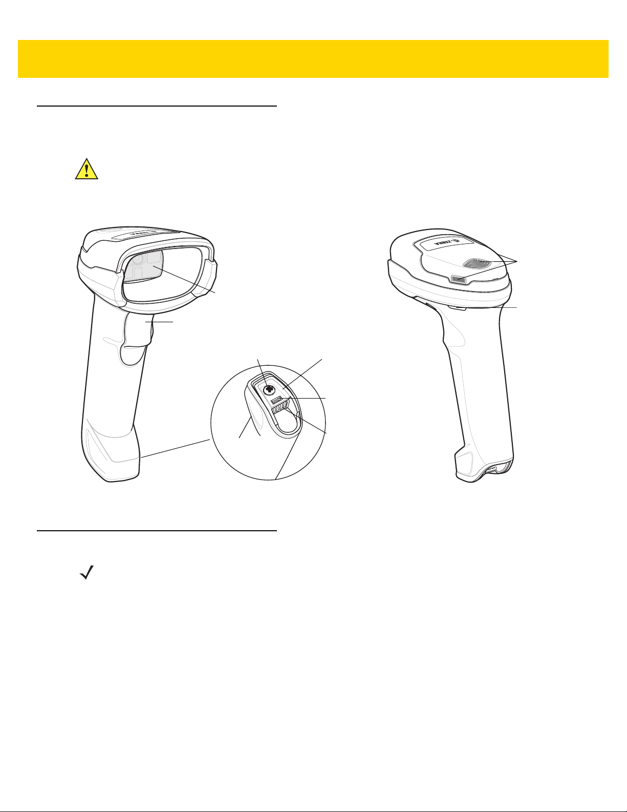
DS2278 Features
Beeper
Scan LEDs
Trigger
Scan Window
Battery
Compartment
Screw
Charging
Contacts
Battery
Compartment
Cover
Micro USB
Port
IMPORTANT DO NOT use the CR2278-PC cradle with any scanners other than the DS2278 digital scanner.
Getting Started 1 - 3
No other cradles are compatible with the DS2278.
DO NOT use the DS2278 digital scanner with any cradles other than the CR2278-PC cradle. No
other scanners are compatible with the CR2278-PC cradle.
Figure 1-2 Digital Scanner Features
For detailed LED indicator information see Beeper and LED Indications on page 3-1.
Cradle Features
NOTE For detailed information about connecting, using, and mounting the CR2278-PC cradle refer to the
documentation included with the crad le (CR2278-PC Presentation Cradle Quick Reference
Guide, p/n MN-002917xx).
The CR2278-PC cordless presentation cradle serves as a charger, radio communication interface, and host
communication interface for the DS2278 cordless digital scanner.
The presentation cradle sits on a desktop and charges the DS2278 cordless digital scanner while allowing bar
code scanning in presentation mode. This cradle also provides host communication by receiving digital scanner
data via a Bluetooth radio, and sending that data to the host through an attached cable. The cable provides power
to the cradle from the host or optional power supply if supported.
For more information about communication between the digital scanner, cradle, and host, see Chapter 6, Radio
Communications.
Page 28
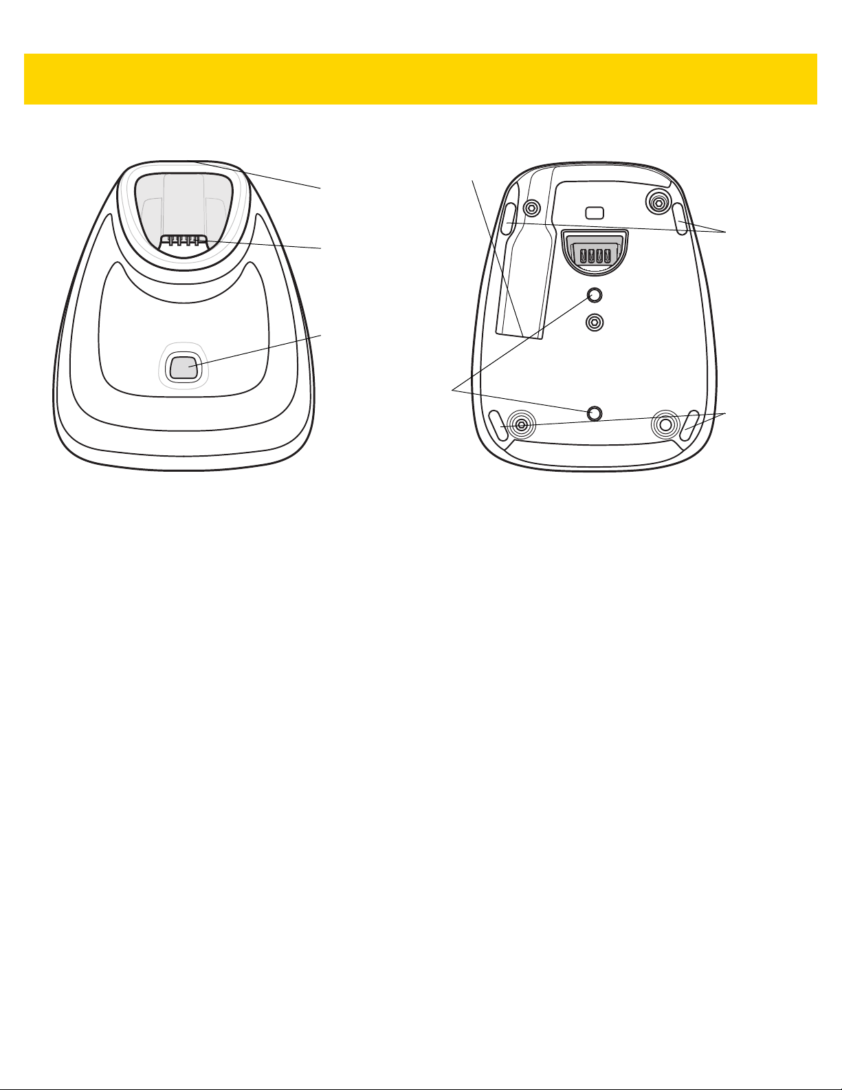
1 - 4 DS2278 Digital Scanner Product Reference Guide
Charging /
Communications
Contacts
Pairing Bar
Code (in back)
Rubber
Feet
Rubber
Feet
Interface Port
Station Mount
Threaded Brass
Screw Holes
(2 - M4 x 5 mm)
LED Indicator
Presentation Cradle
Figure 1-3 CR2278-PC (Presentation Cradle) -Top and Bottom Views
Connecting the Cradle
Via Host Connection (for Charging and Communication)
1. Connect the appropriate cable to the power supply and an AC power source, if necessary. This ensures
detection of the host and prevents inadvertently back powering the cradle from impro pe r dete ctio n of the host.
2. Insert the interface cable into the host port.
3. Insert the interface cable into the cradle's ho st port.
4. Pair the digital scanner to the cradle either by inserting it in the cradle (if Pair on Contacts is enabled) or by
scanning the pairing bar code.
5. If necessary, scan the appropriate host bar code (for non-autodetected interfaces).
Via Wall Outlet Using a Power Adapter (for Charging Only)
1. Connect the appropriate cable to the power supply and an AC power source.
2. Insert the interface cable into the cradle's ho st port.
3. Pair the digital scanner directly to the host device (PC, Smartphone, or Tablet).
Changing the Host Interface
To connect to a different host, or to the same host through a different cable:
1. Unplug the interface cable from the host.
2. Unplug the power supply from the host cable, if required.
3. Connect the interface ca ble to the new host, or the new interface cable to the existing host.
4. Reconnect the power supply, if required.
5. If necessary, scan the appropriate host bar code (for non-autodetected interfaces).
Page 29

Using a DC Power Supply
There is no separate power jack on the cradle. The cradle can operate from host supplied power, if available. If
host power is limited or not available, an external DC power supply can be used with certain host interface cables
that support a power jack. An external power supply is recommended if fastest charging is required. See host
interface chapters for connections.
CAUTION Always disconnect the DC power supply BEFORE disconnecting the cable to the host end or the
cradle may not recognize the new host.
Charging the DS2278 Battery
When using a new battery in the DS2278, the battery may require a charge to be enabled. See Charging the
DS2278 Battery on page 1-5.
NOTES 1. It is recommended to fully charge the battery before first use.
2. Charge time depends on the host type and power source.
3. The CR2278-PC passes 5V to the digital scanner which charges the battery. The charging system on
the DS2278 charges the battery with as much current as possible based on the power source of the
CR2278-PC. This way the input power source is never overloaded and the charge time is made as
short as possible. Charge times lengthen as scanning activity increases when a DS2278 operates in
presentation mode on a CR2278-PC cradle. To optimize charge performance, ensure the digital
scanner is oriented to minimize accidental scan activation.
Getting Started 1 - 5
CAUTION The battery does not charge when the temperature is above 40°C (104°F). When scanning in
presentation mode at temperatures above 40°C (104°F), the battery drains until the temperature drops.
When the battery charge is consumed the digital scanner stops scanning until the temperature drops
and the battery has sufficient time to charge.
To avoid temperature related faults, charge the battery and operate the DS2278 in presentation mode
on a CR2278-PC only within the recommended 0°C to 40°C (32°F to 104°F) range, and ideally within
5°C to 35°C (41°F to 95°F).
Charging Using the Cradle
Insert the battery in the DS2278 and place the DS2278 in the CR22 78-PC cradle (see Inserting the Digital Scanner
in the Cradle on page 1-9). The digital scanner b oots and the cradle LED begin s flashing green to indicate the start
of normal charging.
See Beeper and LED Indications on page 3-1 for detailed LED indicator information.
Page 30
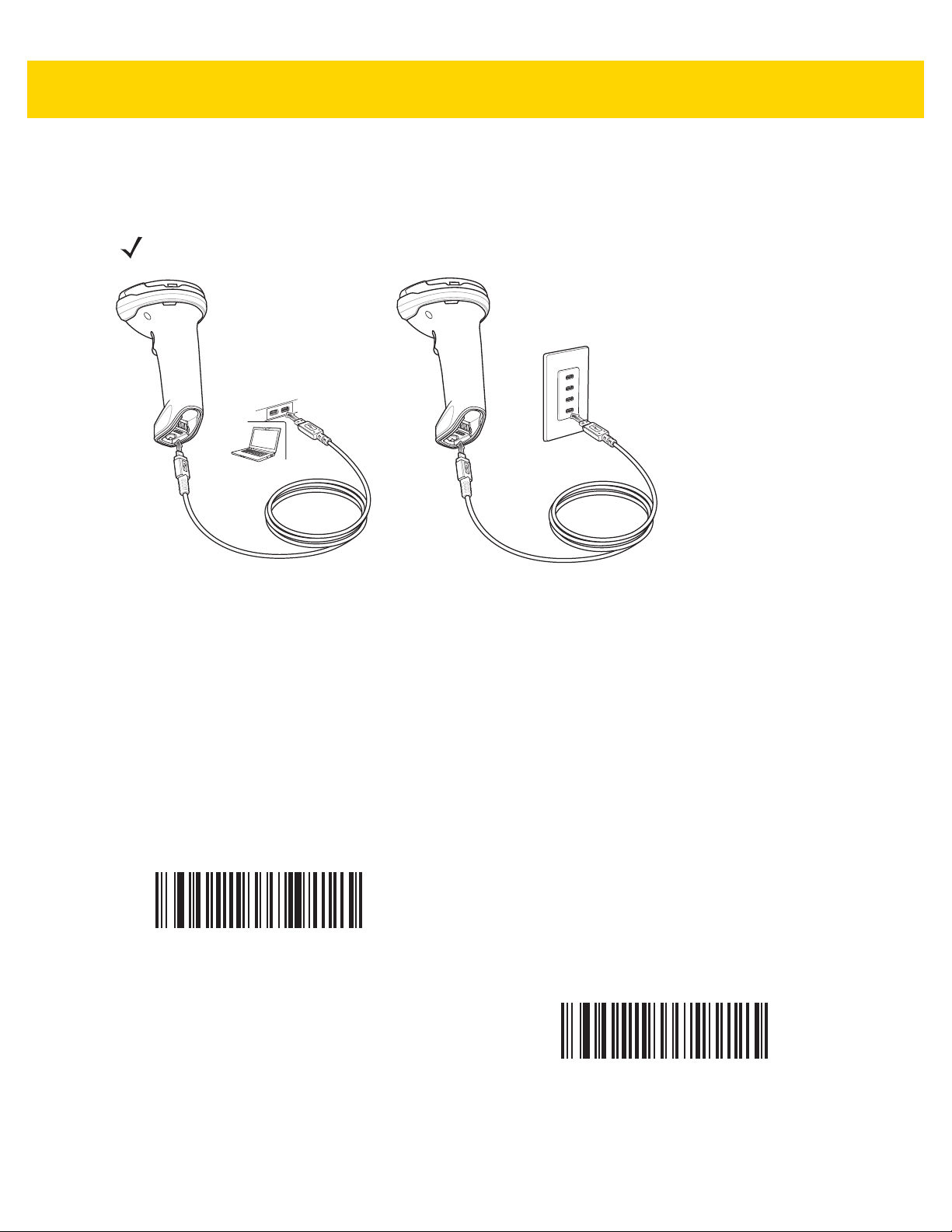
1 - 6 DS2278 Digital Scanner Product Reference Guide
Charging Using the Micro USB Cable
The Micro USB cable is a charge only cable.
NOTE For best performance, we recommend using Zebra accessories.
Figure 1-4 Micro USB Connections
Connect the Micro USB connector to the DS2278. Connect the standard USB connector to a PC or a USB wall
outlet. The digital scanner enumerates as a CDC devi ce when the USB connector is plu gged into a PC host. When
charging begins, the digital scanner LED begins flashing green to indicate the start of normal charging.
Converting a CDC Device to HID
The digital scanner enumerates over USB as a CDC device, by default. If your host does not have a CDC driver, a
delay occurs between connecting the digital scanner to the host and the start of charging. To eliminate the delay
scan HID Device Conversion below to enumerate as an HID device. This allows the scanner to begin chargin g
sooner.
To switch the digital scanner back to a CDC device, scan Scanner as CDC Device below.
HID Device Conversion
For instructions on downloading CDC drivers see page 8-6.
*Scanner as CDC Device
Page 31

Shutting Off the Digital Scanner Battery
Scan the Battery Off bar code below to shut off the battery for long term storage or shipping. Pull the digital
scanner trigger to turn on the battery.
Battery Off
NOTE Always scan the Battery Off bar code in hand-held mode. Also see Battery Preservation Mode on page
5-15 for additional battery features.
Inserting the Battery
Getting Started 1 - 7
NOTES
1. It is recommended to fully charge the battery before first use.
2. The battery is initially shipped inside the digital scanner. Inserting a battery would only be
applicable for a replacement battery.
Figure 1-5 Inserting the Battery
To insert the battery into the digital scanner:
1. Insert the battery into the battery compartment and push down.
2. Turn the screw on the battery compartment clockwise to tighten. Do not over torque the screw.
Page 32

1 - 8 DS2278 Digital Scanner Product Reference Guide
Removing the Battery
IMPORTANT When replacing the battery, wait at least 5 seconds after removing the old battery before
inserting the new battery.
Figure 1-6 Removing the Battery from the Digital Scanner
To remove the battery from the digital scanner:
1. Turn the screw on the battery compartment counterclockwise to remove the screw.
2. Remove the battery from the battery compartment.
3. To replace the battery , see Inserting the Battery on page 1-7.
Page 33

Inserting the Digital Scanner in the Cradle
To insert the digital scanner in the CR2278-PC cradle:
1. Insert the digital scanner straight down into the cradle top.
2. The digital scanner naturally rotates forward to engage the digital scanner contacts with the cradle contacts
Getting Started 1 - 9
Figure 1-7 Inserting the Digital Scanner in the CR2278-PC Cradle
Sending Data to the Host Computer
The cradle receives data from the digital scanner via a wireless radio connection and transmits it to the host
computer via the host cable. The digi tal scann er and cradle must be paired for successful wireless communication.
Pairing
Pairing registers a digital scanner to the cradle such that the digital scanner and cradle can exchange information.
Pair the digital scanner to the cradle either by inserting it in the cradle (if pair on contacts is enabled), or by
scanning the pairing bar code.
To pair the digital scanner with the cradle, insert the digital scanner in the cradle or scan the pairing bar code.
(Pairing on insertion into the cradle is enabled by default. See Pairing Methods on page 6-26.)
NOTE The pairing bar code that connects the digital scanner to a cradle is unique to each cradle.
Do not scan data or parameters until pairing complet es.
Page 34

1 - 10 DS2278 Digital Scanner Product Reference Guide
Lost Connection to Host
If scanned data does not transmit to the cradle's host, ensure that all cables are firmly inserted and the power
supply is connected to an appropriate AC outlet, if applicable. If scanned data still does not transmit to the host,
reestablish a connection with the host:
1. Disconnect the power supply from the cradle.
2. Disconnect the host interface cable from the cradle.
3. Wait three seconds.
4. Reconnect the host interface cable to the cradle.
5. Reconnect the power supply to the cradle, if the host requires.
6. Reestablish pairing with the cradle by inserting the digital scanner in the cradle or scan the pairing bar code.
(Pairing on insertion into the cradle is enabled by default. See Pairing Methods on page 6-26.)
Configuring the Digital Scanner
Use the bar codes in this manual or the 123Scan configuration program to configure the digital scanner. See
Chapter 5, User Preferences & Miscellaneous Options and each host chapter for information about programming
the digital scanner using bar code menus. See Chapter 2, 123Scan and Software Tools to configure the digital
scanner using this configuration program. 123Scan includes a help file.
Radio Communications
The digital scanner can communicate with remote devices via Bluetooth, or by pairing with a cradle. For radio
communication parameters, detailed information about operational modes, Bluetooth and pairing, see Chapter 6,
Radio Communications.
Accessories
The digital scanner ships with the battery installed and the DS2278 Quick Start Guide. The following accessories
must be ordered separately:
• Cradle: Can be used for charging the digital scanner battery and host communication (see Presentation
Cradle on page 1-4).
• Micro USB cable: Can be used for charging the battery in the digital scanner, without a cradle.
• Replacement battery for the DS2278 digital scanner, if needed.
• Interface cable for the appropriate interface.
• Power supply, if the interface requires one.
See Related Product Line Configurations on page xx for the full list of accessories. Also see Configurations on
page xix for product and cradle configurations. For additional items, contact a local Zebra representative or
business partner.
Page 35

CHAPTER 2 123SCAN AND
SOFTWARE TOOLS
Introduction
This chapter briefly describes the Zebra software tools available for customizing scanner operation.
123Scan
123Scan is a software tool that simplifies scanner setup and more.
Intuitive enough for first time users, the 123Scan wizard guides users through a streamlined setup process.
Settings are saved in a configuration file that can be printed as a single programming bar code for scanning,
emailed to a smart phone for scanning from its screen, or downloaded to the scanner using a USB cable.
Through 123Scan a user can accomplish the following.
• Configure a scanner using a wizard.
• Program the following scanner settings:
• Beeper tone / volume settings.
• Enable / disable symbologies.
• Communication settings.
• Modify data before transmission to a host using:
• Advanced Data Formatting (ADF) - Scan one bar code per trigger pull.
• Load parameter settings to a scanner via:
• Bar code scanning.
• Scan a paper bar code.
• Scan a bar code from a PC screen.
• Scan a bar code from a smart phone screen.
• Download over a USB cable:
• Load settings to one scanner.
• Stage up to 10 scanners simultaneously (Powered USB Hub recommended with 0.5 amp / port).
Page 36

2 - 2 DS2278 Digital Scanner Product Reference Guide
• Validate scanner setup:
• View scanned data within the utility's Data View screen.
• Review settings using the Parameter Report.
• Clone settings from an already deployed scanner from the start screen.
• Upgrade scanner firmware:
• Stage up to 10 scanners simultaneously (Powered USB Hub recommended with 0.5 amp / port).
• Upgrade firmware
• Over a USB cable
• Over a Bluetooth connection (no cradle required)
• View statistics such as:
• Asset tracking information.
• Time and usage information.
• Bar codes scanned by symbology.
• Generate the following reports:
• Bar Code Report - Programming bar code, included parameter settings, and supported scanner models.
• Parameter Report - Lists parameters programmed within a configuration file.
• Inventory Report - Lists scanner asset tracking information.
• Validation Report - Printout of scanned data from the Data view.
• Statistics Report - Lists all statistics retrieved from the scanner.
For more information go to: www.zebra.com/123Scan
.
Communication with 123Scan
Use a USB cable to connect the scanner to a Windows host computer r unning 123Scan.
123Scan Requirements
• Host computer with Windows XP, 7, 8, or 10
• Scanner
123Scan Information
For more information on123Scan, go to: www.zebra.com/123Scan.
For a 1 minute tour of 123Scan, go to: www.zebra.com/ScannerHowToVideos
To see a list of all of our free software tools, go to: www.zebra.com/scannersoftware
.
.
Page 37

Scanner SDK, Other Software Tools, and Videos
To tackle all scanner programming needs, use Zebra’s diversified set of software tools. Whether staging a device
or developing a fully featured application with image and data capture, as well as asset management, these tools
help you every step of the way. To download any of the following free tools, go to:
www.zebra.com/scannersoftware
• 123Scan configuration utility
• SDKs
• Scanner SDK for Windows
• Scanner SDK for Linux
• Scanner SDK for Android
• Scanner SDK for iOS
• Drivers
• OPOS driver
• JPOS driver
• USB CDC driver
• TWAIN driver
• Scanner Management Service (SMS) for Remote Management
• Windows
• Linux
• Mobile Apps
• Scanner Control App
•Android
•iOS
• Zebra AppGallery
• Scan-To-Connect Utility
•Android
• Windows
• How-To-Videos
.
123Scan and Software Tools 2 - 3
NOTE For a list of SDK supported scanner functionality by communication protocol, see
Appendix J, Communication Protocol Functionality.
Page 38

2 - 4 DS2278 Digital Scanner Product Reference Guide
Scanner Control App
The Scanner Control App (SCA) allows you to contr ol a Bluetooth scanner fro m a p hone or table t with out a cr adle.
Use this app to showcase Zebra Bluetooth scanner capabilities and ease of control right from your phone.
The Scanner Control App supports Scan-To-Connect technology for one-step Bluetooth pairing and allows you to
control the following scanner functions:
• Program the beeper and LEDs
• Enable and disable symbologies
• Remotely trigger a scan
The app displays scanned bar code data, and can query scanner asset information and battery health statistics.
The Scanner Control App also works with USB connected scanners like the MP7000, assuming your Android tablet
has a powered USB host port.
The Scanner Control app is available on the Android Play, iOS App, and Zebra AppGallery stores. Source code is
available within the Zebra Scanner SDK for Android and iOS.
To watch a 1 minute tour of the Scanner Control App, go to: www.zebra.com/scannercontrolapp
Scan-To-Connect (STC) Utility
In one step, connect a Zebra Bluetooth scanner to a phone, tablet or PC by simply scanning an STC bar code.
Available as a standalone utility for Wi ndows a nd Android operating systems from www.zebra.com/scantoconnect
Source code is also available for easy app integration.
NOTE The STC utility allows you to pair a Bluetooth scanner to a phone, tablet or PC without usin g a cradle.
Advanced Data Formatting (ADF)
Advanced Data Formatting (ADF) is a means of customizing data before transmission to the host device. Use ADF
to edit scan data to suit host application requirements. With ADF you scan one bar code per trigger pull. ADF is
programmed using 123Scan.
To watch a video on Creating an Advanced Data Formatting (ADF) Rule, go to:
www.zebra.com/ScannerHowToVideos
For additional information, refer to the Advanced Data Formatting Programmer Guide, p/n 72E-69680-xx.
.
.
.
Page 39

CHAPTER 3 DATA CAPTURE
Introduction
This chapter provides beeper and LED definitions, techniqu es involved in scanning bar codes, general instructions
and tips about scanning, and decode ranges.
This chapter provides beeper and LED definitions, techniqu es involved in scanning bar codes, general instructions
and tips about scanning, and decode ranges.
Beeper and LED Indications
The digital scanner issues different beep sequences/patterns and an LED display to indicate status. Table 3-1
defines beep sequences/patterns and LED displays which occur during both normal scanning and while
programming the digital scanner.
Digital Scanner Indications
Table 3-1 Digital Scanner Beeper and LED Indications
Beeper Sequence LED Indication
Standard Use
Low/medium/high beeps Green Power up.
Scanning
None Green solid Presentation Mode on.
None No LED; green LED is
turned off
Medium beep
(or as configured)
Green flash A bar code was successfully decoded. (See
Presentation Mode off.
Preferences/Miscellaneous Options Parameter
Defaults on page 5-2
User
for programming beeper sounds.)
Page 40

3 - 2 DS2278 Digital Scanner Product Reference Guide
Table 3-1 Digital Scanner Beeper and LED Indications (Continued)
Beeper Sequence LED Indication
Low/low/low/extra low
beeps
Four long low beeps Red A transmis sion error was detected in a scanned sy mbol.
Five long low beeps Red Conversion or format error.
None Red (fast blink)) on
High None A <BEL> character is received over RS-232.
None Single green flash Scanner dock in the cradle.
Wireless Operation
Low, high, low, high Red Out of batch storage memory, unable to store new bar
Radio Indications
Low None Digital scanner inserted into a cradle (may be disabled).
Low, high Green Bluetooth connection established.
High, low Red Bluetooth disconnection event.
Red Parity error .
The data is ignored. This occurs if a unit is not properly
configured. Check option setting.
Digital scanner is disabled by a host command to the
trigger pull
digital scanner .
code.
Long low, long high Red Bluetooth page timeout; remote device is out of
range/not powered.
Long low, long high, long
low, long high
None Green (fast blink) Bluetooth attempting reconnection.
Five high Green (fast blink) Bluetooth attempting reconnection (default is disable).
None Green (fast blink) Digital scanner placed into limited discoverable mode.
High, Low, High, Low Green Pairing bar code scanned.
Battery Indications
Four short high beeps Red (stays on for 4
None Solid green Digital scanner is charging.
None Red (solid) Digital scanner charging error occurred.
Battery Indications - Micro USB Only
None Green (fast continuous
None Green (solid) Digital scanner is fully charged.
None Bluetooth connection attempt was rejected by remote
device.
Low battery indication (on trigger release).
seconds)
Digital scanner is charging.
blink)
Page 41

Table 3-1 Digital Scanner Beeper and LED Indications (Continued)
Beeper Sequence LED Indication
None Single green flash Initial connection.
None Red (solid) Charge error.
Parameter Programming
Data Capture 3 - 3
Long low/long high beeps Red Input error, incorrect bar code or
wrong entry, incorrect bar code programming
sequence; remain in program mode.
High/low beeps Green Keyboard parameter selected. Enter value using bar
code keypad.
High/low/high/low beeps Green Successful program exit with change in the parameter
setting.
ADF Programming
Low/high/low beeps None ADF transmit error.
High/low beeps Green Number expected. Enter another digit. Add leading
zeros to the front if necessary.
Low/low beeps Green Alpha expected. Enter another alphabetic character or
scan the
High/high beeps Green blinking ADF criteria or action is expected. Enter another criteria
or action or scan the
High/low/low beeps Green All criteria or actions cleared for current rule, continue
entering rule.
High/low/high/low beeps Green
(turns off blinking)
Rule saved. Rule entry mode exited.
End of Message
Save Rule
Cancel
bar code.
bar code.
scanned,
Long low/long high beeps Red Rule error. Entry error, wrong bar code scanned, or
criteria/action list is too long for a rule. Re-enter criteria
or action.
Low beep Green Deleted last saved rule. The current rule is left intact.
Low/high/high beeps Green All rules deleted.
Long low/long high/long
low/long high beeps
Long low/long high/long low
beeps
Macro PDF
Two low beeps None File ID error. A bar code not in the current MPDF
Two long low beeps None File ID error. A bar code not in the current MPDF
Red Out of rule memory. Erase some existing rules, then try
to save rule again.
Green
(turns off blinking)
Cancel rule entry. Rule entry mode exited because of
an error or the user asked to exit rule entry.
sequence was scanned.
sequence was scanned.
Page 42

3 - 4 DS2278 Digital Scanner Product Reference Guide
Table 3-1 Digital Scanner Beeper and LED Indications (Continued)
Beeper Sequence LED Indication
Three long low beeps None Out of memory. There is not enough buffer space to
store the current MPDF symbol.
Four long low beeps None Bad symbology. Scanned a 1D or 2D bar code in a
MPDF sequence, a duplicate MPDF label, a label in
an incorrect order , or trying to transmit an empty or
illegal MPDF field.
Five long low beeps None Flushing MPDF buffer.
Fast warble beep None Aborting MPDF sequence.
Low/high beeps None Flushing an already empty MPDF buffer.
Host Specific
USB only
Four high beeps None
RS-232 only
High/high/high/low beeps Red RS-232 receive error.
High beep None A <BEL> cha racter is recei ved when Beep on <BEL> is
Host Controlled Digital Scanner LEDs
None Green (slow blink) Digital scanner connected to 123Scan.
None Red (fast blink) File being transferred to the digital scanner (parameters
None Red (slow blink) Firmware being activated on the digital scanner, loaded
None Green (solid) Programming completed successfully (parameters and
None Red (blink) Loading the SMS package to the digital scanner.
None Red (solid) Error state.
Digital
scanner has not completed initialization. Wait
several seconds and scan again.
enabled.
and firmware).
into memory.
firmware).
Page 43

Cradle LED Indications
Table 3-2 Cradle LED Indications
LED Indication
Standard Use
Green (solid) Power up.
Green (off, then on) Bluetooth connection established.
Red (blink) Transmission error.
Charging
Amber (blink) Charging.
Green (solid) Fully charged.
Amber (fast blink) Charging error.
Data Capture 3 - 5
Maintenance
Red (solid) Enter boot loader.
Red (blink) Firmware installation.
Table 3-3 lists the conditions in which the specified host controls the System Indicator LED.
Table 3-3 Host Controlled Cradle LED Indications
LED Indication
123Scan
Slow Blinking Green Digital scanner connected to 123Scan.
Fast Blinking Red File being transferred to the digital scanner (parameters and firmware).
Slow Blinking Red Firmware activated on the digital scanner, loaded into memory.
Solid Green Programming completed successfully (parameters and firmware).
Solid Red Error state.
SMS
Blinking Red
(Both digital scanner and cradle)
Loading the SMS package to digital scanner.
Page 44

3 - 6 DS2278 Digital Scanner Product Reference Guide
Scanning
Hand-Held Scanning
1. Place the aiming pattern over the bar code.
Figure 3-1 Aiming Pattern on Bar Code - Hand-Held Mode
2. Press and hold the trigger until either:
a. The digital scanner r eads the bar code. The digital scann er beeps, the LED flashes, and the scan line turns
off.
Or
b. The digital scanner does not read the bar code and the scan line turns off.
3. Release the trigger.
Page 45

Data Capture 3 - 7
Hands-Free Scanning
The digital scanner is in hands-free (presentation) mode when it sits in the CR2278-PC cradle. During idle
conditions the digital scanner operates in object detection mode, where it automatically wakes up to decode a bar
code presented in the field of view. In object detection mode it is normal for the illumination LEDs to be dimly lit.
To scan:
1. Ensure all connections are secure (see appropriate host chapter).
2. Present the bar code in the digital scanner field of view.
3. Upon successful decode, the dig ital scanner beeps and the LED flashes green. (For more information about
beeper and LED definitions, Beeper and LED Indications on page 3-1).
Figure 3-2 Aiming Pattern on Bar Code - Hands-Free Mode
Page 46

3 - 8 DS2278 Digital Scanner Product Reference Guide
012345
012345
Aiming with Digital Scanner
Aiming
When scanning, the digital scanner projects a red scan line which allows positioning the bar code within its field of
view, omnidirectionally. See Decode Ranges on page 3-8 for the proper distance to achieve between the digital
scanner and a bar code.
Figure 3-3 Scanning Orientation with Aiming Line
The aiming line is smaller when the digital scanner is closer to the symbol and larger when it is farther from the
symbol. Scan symbols with smaller bars or elements (mil size) closer to the digital scanner, and those with larger
bars or elements (mil size) farther from the digital scanner.
The digital scanner beeps to indicate that it successfully decoded the bar code. For more informa tion see Table 3-1
on page 3-1.
Decode Ranges
Table 3-4 DS2278 Typical Decode Ranges
Bar Code Type Symbol Density
Code 39 5 mil .2 in/.5 cm 6.0 in/15.2 cm
Code 39 10 mil .0 in/.0 cm 13.0 in/33.0 cm
Code 128 5 mil .6 in/1.5 cm 4.0 in/10.1 cm
Code 128 7.5 mil .0 in/.0 cm 7.0 in/17.8 cm
PDF417 6.7 mil .8 in/2.0 cm 5.7 in/14.5 cm
UPC 13 mil (100%) .5 in/1.3 cm 14.5 in/36.8 cm
Typical Working Ranges
DS2278
Near
(in/cm)
Far
(in/cm)
Data Matrix 10 mil .3 in/.8 cm 6.2 in/15.7 cm
QR 20 mil .0 in/.0 cm 11.0 in/27.9 cm
* Printing resolution, contrast, and ambient light dependent.
Page 47

CHAPTER 4 MAINTENANCE,
TROUBLESHOOTING, &
TECHNICAL
SPECIFICATIONS
Introduction
This chapter provides suggested digital scanner maintenance, troubleshoo ting, technical specifications, and signa l
descriptions (pinouts).
Maintenance
IMPORTANT Use pre-moistened wipes and do not allow liquid cleaner to pool.
Known Harmful Ingredients
The following chemicals are known to damage the plastics on Zebra scanner s and shoul d not come in con tact with
the device:
• Acetone
• Ammonia solutions
• Aqueous or alcoholic alkaline solutions
• Aromatic and chlorinated hydrocarbons
• Benzene
• Carbolic acid
• Compounds of amines or ammonia
• Ethanolamine
• Ethers
• Isopropyl alcohol 70% (including wipes)
• Ketones
• TB-lysoform
• Toluene
• Trichloroethylene.
Page 48

4 - 2 DS2278 Digital Scanner Product Reference Guide
Approved Cleaners for the Digital Scanner and Cradle
• Hydrogen peroxide
• Mild dish soap.
Cleaning the Digital Scanner
Routinely cleaning the exit window is required. A dirty window may affect scanning accuracy. Do not allow any
abrasive material to touch the window.
To clean the digital scanner:
1. Dampen a soft cloth with one of the app roved cleaning agents listed above or use pre-moistened wipes.
2. Gently wipe all surfaces, including the front, back, sides, top and bottom. Never apply liquid directly to the
digital scanner. Be careful not to let liquid pool around the digital scanner window, trigger, cable connector or
any other area on the device.
3. Be sure to clean the trigg er and in between the tr igger and the ho using (use a cotton- tipped applicator to rea ch
tight or inaccessible areas).
4. Do not spray water or other cleaning liquids directly into the exit window.
5. Wipe the digital scanner exit window with a lens tissue or other material suitable for cleaning optical material
such as eyeglasses.
6. Immediately dry the digital scanner window after cleaning with a soft non-abrasive cloth to prevent streaking.
7. Allow the unit to air dry before use .
8.
Digital s
a. Dip the cotton portion of a cotton-tipped applicator in an approved cleaner.
b. Rub th e cot to n po rtion of the cotton-tipped applicator back-and-forth across the connector on the Zebra
canner connectors:
digital scanner at least 3 times. Do not leave any cotton residue on the connector.
c. Use the cotton-tipped applicator dipped in alcohol to remove any grease and dirt near the connector area.
d. Use a dry cotton tipped applicator and rub the cotton portion of the cotton-tipped applicator back-and-forth
across the connectors at least 3 times. Do not leave any cotton residue on the connectors.
Page 49

Troubleshooting
Table 4-1 Troubleshooting
Problem Possible Causes Possible Solutions
Maintenance, Troubleshooting, & Technical Specifications 4 - 3
The aiming pattern does not
appear when pressing the
trigger.
Digital scanner emits aiming
pattern, but does not decode
the bar code.
No power to the digital scanner. If the configuration requires a power
supply, re-connect the power supply.
Incorrect host interface cable is
used.
Interface/power cables are loose. Re-connect cables.
Digital scanner is disabled. For IBM 468x and USB IBM Hand-held,
If using RS-232 Nixdorf B mode,
CTS is not asserted.
Aiming pattern is disabled. Enable the aiming pattern. See Hand-Held
Digital scanner is not programmed
for the correct bar code type.
Bar code symbol is unreadable. Scan test symbols of the same bar code
Connect the correct host interface cable.
IBM Table-T op, an d OPOS modes, enable
the digital scanner via the host interface.
Otherwise, see the technical person in
charge of scanning.
Assert CTS line.
Decode Aiming Pattern on page 5-18.
Program the digital scanner to read that
type of bar code. See Chapter 13,
Symbologies.
type to determine if the bar code is
defaced.
The symbol is not completely inside
aiming pattern.
Distance between digital scanner
and bar code is incorrect.
Move the symbol completely within the
aiming pattern.
Move the symbol completely within the
field of view (AIM pattern does NOT define
FOV)
Move the digital scanner closer to or
further from the bar code. See Decode
Ranges on page 3-8.
Page 50

4 - 4 DS2278 Digital Scanner Product Reference Guide
Table 4-1 Troubleshooting (Continued)
Problem Possible Causes Possible Solutions
Digital scanner decodes bar
code, but does not transmit
the data to the host.
Digital scanner is not programmed
for the correct host type.
Interface cable is loose. Re-connect the cable.
Cradle is not programmed for the
correct host type.
Digital scanner is not paired to host
connected interface.
Cradle has lost connection to the
host.
If the digital scanner emits four long
low beeps, a transmission error
occurred.
This occurs if a unit is not properly
configured or connected to the
wrong host type.
If the digital scanner emits five low
beeps, a conversion or format error
occurred.
Scan the appropriate host type
programming bar code. See the chapter
corresponding to the host type.
Check digital scanner host parameters or
edit options.
Pair digital scanner to the cradle by
scanning the PAIR bar code on the cra dle .
In this exact order: disconnect power
supply; disconnect host cable; wait three
seconds; reconnect host cable; reconnect
power supply; reestablish pairing.
Set the digital scanner's communication
parameters to match the host's setting.
Configure the digital scanner's conversion
parameters properly.
Host displays scanned data
incorrectly.
Digital scanner emits short
low/short medium/short high
beep sequence (power-up
beep sequence) more than
once.
If the digital scanner emits
low/high/low beeps, it detected an
invalid ADF rule.
Digital scanner is not programmed
to work with the host.
The USB bus may put the digital
scanner in a state where power to
the digital scanner is cycled on and
off more than once.
Program the correct ADF rules. Refer to
the Advanced Data Formatting
Programmer Guide.
Scan the appropriate host type
programming bar code.
For RS-232, set the digital scanner's
communication parameters to match the
host's settings.
For a Keyboard Wedge configuration,
program the system for the correct
keyboard type, and turn off the CAPS
LOCK key.
Program the proper editing options (e.g.,
UPC-E to UPC-A Conversion).
Normal during host reset.
Page 51

Maintenance, Troubleshooting, & Technical Specifications 4 - 5
Table 4-1 Troubleshooting (Continued)
Problem Possible Causes Possible Solutions
Digital scanner emits four
short high beeps during
decode attempt.
Digital scanner emits
Low/low/low/extra low beeps
when not in use.
Digital scanner emits
low/high beeps during
programming.
Digital scanner emits
low/high/low/high beeps
during programming.
Digital scanner emits
low/high/low beeps.
Digital scanner has not completed
USB initialization.
RS-232 receive error. Normal during host reset. Otherwise, set
Input error, incorrect bar code or
Cancel bar code was scanned.
Out of host parameter storage
space.
Out of memory for ADF rules. Reduce the number of ADF rules or the
During programming, indicates out
of ADF parameter storage space.
ADF transmit error. Refer to the Advanced Data Formatting
Invalid ADF rule is detected. Refer to the Advanced Data Formatting
Wait several seconds and scan again.
the digital scanner's RS-232 parity to
match the host setting.
Scan the correct numeric bar codes within
range for the parameter programmed.
Scan Default Parameters on page 5-5.
number of steps in the ADF rules.
Erase all rules and re-program with shorter
rules.
Guide for information.
Guide for information.
Digital scanner emits a
power-up beep after
changing USB host type.
Digital scanner emits one
high beep when not in use.
Digital scanner emits
frequent beeps.
The USB bus re-established power
to the digital scanner.
In RS-232 mode, a <BEL>
character was received and Beep
on <BEL> option is enabled.
No power to the digital scanner. Check the system power. If the
Incorrect host interface cable is
used.
Interface/power cables are loose. Check for loose cable connections and
Normal when changing USB host type.
Normal when Beep on <BEL> is enabled
and the digital scanner is in RS-232 mode.
configuration requires a power supply,
re-connect the power supply.
Verify that the correct host interface cable
is used. If not, connect the correct host
interface cable.
re-connect cables.
Page 52

4 - 6 DS2278 Digital Scanner Product Reference Guide
Table 4-1 Troubleshooting (Continued)
Problem Possible Causes Possible Solutions
Digital scanner emits five
long low beeps after a bar
code is decoded.
The digital scanner does not
connect to the
tablet/PC/phone using a
Bluetooth Serial connection
(SPP) or while emulating a
Bluetooth keyboard (HID).
Conversion or format error was
detected.
The digital scanner’s conversion
parameters are not properly
configured.
Conversion or format error was
detected.
An ADF rule was set up with
characters that can't be sent for the
host selected.
Conversion or format error was
detected.
A bar code was scanned with
characters that can't be sent for that
host.
N/A 1.Turn off and then turn back on the
Ensure the digital scanner’s conversion
parameters are properly configured.
Change the ADF rule, or change to a host
that can support the ADF rule.
Change the bar code, or change to a host
that can support the bar code.
Bluetooth radio on the tablet/PC/phone.
A reboot of the tablet/PC/phone may be
required.
or
2. Remove the device from the PC. Scan
Set Factory Defaults on page 5-5 and
reconfigure the digital scanner from
scratch.
When trying to pair the
digital scanner and cradle by
scanning the pairing bar
code on the CR2278, the
digital scanner emits a
rejection beep.
Digital s
even if the pairing request
was canceled from remote
iOS/Android device.
There is a delay before
illumination and aim turn on
after a trigger pull.
There are firmware update
failures (the firmware
download does not go
through).
canner LED blinks
Pairing attempt occurs after
scanning Set Factory Defaults.
If pass key entry is canceled from
the tablet/phone, the digital scanner
remains in the pass key entry mode
for 30 seconds before timing out.
N/A Increase Time Delay to Low Power Mode
N/A Increase Time Delay to Low Power Mode
After scanning Set Factory Defaults
either insert the digital scanner in the
cradle to pair or wait five seconds before
scanning the pairing bar code on the
cradle.
To exit pass key entry mode scan Cancel
on page H-1 or scan any other bar code.
on page 5-12 to help with radio wake up.
Note: This could impact overall battery
life.
on page 5-12 to help with radio wake up.
Page 53

Maintenance, Troubleshooting, & Technical Specifications 4 - 7
NOTE If after performing these checks the digital scanner still experiences problems, contact the distributor or
call support.
Report Software Version Bar Code
When contacting support, a support representative may ask you to scan the bar code below to determine the
version of software installed in the digital scanner.
Report Software Version
Page 54

4 - 8 DS2278 Digital Scanner Product Reference Guide
Technical Specifications
Table 4-2 Technical Specifications
Item Description
Physical Characteristics
Dimensions
Digital s
Presentation Cradle
Weight
Digital s
Presentation Cradle
Input Voltage Range (DS2278 and Cradle) 4.5 to 5.5 VDC Host Powered; 4.5 to 5.5 VDC External Power Supply
canner
canner
6.9 in. H x 2.6 in. W x 3.5 in. D
17.5 cm. H x 6.6 cm. W x 9.0 cm. D
2.8 in. H x 3.7 in. W x 4.8 in. D
7.2 cm. H x 9.4 cm. W x 12.2 cm. D
7.5 oz. / 214 g
5.2 oz. / 151 g
Current (Presentation Cradle and Micro USB
Cable)
Color Nova White, Twilight Black
Supported Host Interfaces USB, RS-232, Keyboard Wedge, TGCS (IBM) 46XX over RS-485
Keyboard Support Supports over 90 international keyboards
User Indicators Direct Decode Indicator, Good Decode LEDs, Rear View LEDs,
Performance Characteristics
Motion Tolerance (Hand-Held) Up to 5 in./13 cm. per second for 13 mil UPC
Swipe Speed (Hands-Free) Up to 30.0 in./76.2 cm. per second for 13 mil UPC
Aiming Pattern Linear 624nm Amber LED
Illumination Two 645nm Super-Red LEDs
Imager Field of View 32.8° H x 24.8° V Nominal
Image Sensor 640 x 480 pixels
Minimum Print Contrast 25% minimum reflective difference
500 mA (typical) Standard USB; 1100 mA (typical) BC 1.2 USB
Beeper (adjustable tone and volume)
Skew Tolerance +/- 65°
Pitch Tolerance +/- 65°
Roll Tolerance 0° - 360°
User Environment
Operating Temperature
Digital s
Presentation Cradle
canner
32.0° to 122.0° F/0.0° to 50.0° C
32.0° to 104.0° F/0.0° to 40.0° C
Page 55

Maintenance, Troubleshooting, & Technical Specifications 4 - 9
Table 4-2 Technical Specifications (Continued)
Item Description
Storage Temperature -40.0° to 158.0° F/-40.0° to 70.0° C
Humidity 5% to 95% RH, non-condensing
Drop Specification Designed to withstand multiple drops at 5.0 ft./1.5 m to concrete
Tumble Specification Designed to withstand 250 tumbles in 1.5 ft./.5 m tumbler
Note: 1 tumble = 0.5 cycle
Environmental Sealing IP42
Electrostatic Discharge (ESD) DS2278 and Presentation Cradle: ESD per EN61000-4-2, +/-15 KV
Air, +/-8 KV Direct, +/-8 KV Indirect
Ambient Light Immunity 0 to 10,000 Foot Candles / 0 to 107,600 Lux
Radio Specifications
Bluetooth Radio Standard Bluetooth Version 4.0 with BLE: Class 2 33 ft. (10.0m),
Serial Port and HID Profiles; output power adjustable down from 2.0
dBm in 8 Steps
Battery
Battery Capacity/Battery Type 2,400 mAh Li-Ion Battery
Scans Per Battery Charge 110,000 scans at 60 scans per minute or 50,000 scans at 10 scans
per minute
Note: Simulated Checkout profile of 10 scans in 10 seconds with a 50
second rest.
Operating Time Per Full Charge 84.0 hours
Note: Simulated Checkout profile of 10 scans in 10 seconds with a 50
second rest.
Charge Time (from Empty)
Standard USB
BC1.2 USB
External 5V Source
Micro USB
BC1.2 Micro USB
Symbol Decode Capability
1D Code 39, Code 128, Code 93, Codabar/NW7, Code 11, MSI Plessey,
14 Hour Shift Hours Full Charge Hours
417
15
15
1.5 7
14
UPC/EAN, Interleaved 2 of 5, Korean 3 of 5, GS1 DataBar, Base 32
(Italian Pharma)
Page 56

4 - 10 DS2278 Digital Scanner Product Reference Guide
Table 4-2 Technical Specifications (Continued)
Item Description
2D PDF417, Composite Codes, TLC-39, Aztec, DataMatrix, MaxiCode,
QR Code, Micro QR, Han Xin (Chinese Sensible), Postal Codes
Minimum Element Resolution
Code 39 4.0 mil
Code 128 4.0 mil
Data Matrix 6.0 mil
QR Code 6.7 mil
Utilities and Management
123Scan Programs digital scanner parameters, upgrades firmware, provides
scanned bar code data and prints reports (see Chapter 2, 123Scan
and Software Tools).
Symbol Scanner SDK Generates a fully-featured scanner application, including
documentation, drivers, test utilities and sample source code
(www.zebra.com/ScannerSDKforWindows
Scanner Management Service (SMS) Remotely manages your Zebra scanner and queries its asset
information (www.zebra.com/sms
).
)
Page 57

Cradle Signal Descriptions
PIN 1
PIN 4
Maintenance, Troubleshooting, & Technical Specifications 4 - 11
Figure 4-1 Cradle Pinouts
The signal descriptions in Table 4-3 apply to the contacts on the digital scanner an d are for reference only.
Table 4-3 Signal Pinouts
Pin Function
15VDC
2 USB_D3USB_D+
4 Ground
The signal descriptions in Table 4-4 apply to the connectors on the DS2278 digital scanner and are for reference
only .
Table 4-4 DS2278 Digital Scanner Signal Pin-outs
Pin USB RS-232 Keyboard Wedge IBM
1 Short to Pin 6 Reserved 1M Resistor to Pin 8 2M Resistor to Pin 8
2 Power Power Power Power
3 Ground Ground Ground Ground
4 Reserved TXD KBD_CLK IBM_TXD
5 D + RXD TERM_DATA IBM_RXD
Page 58

4 - 12 DS2278 Digital Scanner Product Reference Guide
Table 4-4 DS2278 Digital Scanner Signal Pin-outs (Continued)
Pin USB RS-232 Keyboard Wedge IBM
6 Short to Pin 1 RTS KBD_DATA IBM_DIR
7 D - CTS TERM_CLK Reserved
8 Reserved Reserved 1M Resistor to Pin 1 2M Resistor to Pin 1
9 Reserved Reserved Reserved Reserved
10 Reserved Reserved Reserved Reserved
SHELL Shield Shield Shield Shield
Page 59

CHAPTER 5 USER PREFERENCES &
*Enable Parameter
(1)
Feature/option
* Indicates default
Option value
MISCELLANEOUS
OPTIONS
Introduction
You can program the scanner to perform various functions, or activate different features. This chapter describes
user preference features and provides programming bar co des for selecting these features.
The scanner ships with the settings shown in Table 5-1 on page 5-2 (also see Appendix A, Standard Default
Parameters for all defaults). If the default values suit requirements, programming is not necessary.
Setting Parameters
To set feature values, scan a single bar code or a short bar code sequence. The settings are stored in non-volatile
memory and are preserved even when th e sca nn e r po wer s do wn .
If not using the default host, select the host type (see each host chapter for specific host information) after the
power-up beeps sound. This is only necessary upon the first power-up when connected to a new host.
To return all features to default values, see Default Parameters on page 5-5. Throughout the programming bar
code menus, asterisks indicate (
NOTE Most computer monitors allow scanning bar codes directly on the screen. When scanning from the screen,
be sure to set the document magnification to a level where you can see the bar code clearly, and bars
and/or spaces do not merge.
*) default values.
Page 60

5 - 2 DS2278 Digital Scanner Product Reference Guide
Scanning Sequence Examples
In most cases, scanning one bar code sets the parameter va lue. For example, to set the beep er tone to high , scan
the High Frequency (beeper tone) bar code listed under Beeper Tone on page 5-8. The scanner issues a fast
warble beep and the LED turns green, signifying a successful parameter entry.
Other parameters, such as Serial Response Timeout or Data Transmission Formats, require scanning several
bar codes. See the parameter descriptions for this procedure.
Errors While Scanning
Unless otherwise specified, to correct an error during a scanning sequence, just re-scan the correct para meter.
User Preferences/Miscellaneous Options Parameter Defaults
Table 5-1 lists defaults for user preferences parameters. Change these values in one of two ways:
• Scan the appropriate bar codes in this chapte r. The new value replaces the standard default value in
memory. To recall default parameter values, see Default Parameters on page 5-5.
• Configure the scanner using the 123Scan
Tools.
configuration program. See Chapter 2, 123Scan and Software
NOTE See Appendix A, Standard Default Parameters for all user preference, host, symbology, and
miscellaneous default parameters.
Table 5-1 User Preferences Parameter Defaults
Parameter
User Preferences
Set Default Parameter N/A N/A N/A
Parameter Bar Code Scanning 236 ECh Enable
Beep After Good Decode 56 38h Enable
Beeper Volume 140 8Ch High
Beeper Tone 145 91h Medium
Beeper Duration 628 F1h 74h Medium
Suppress Power Up Beeps 721 F1h D1h Do Not Suppress
LED on Good Decode 744 F1h E8h Enable
Direct Decode Indicator 859 F2h 5Bh Disable
Parameter
Number
1
SSI
Number
2
Default
Page
Number
5-5
5-6
5-6
5-7
5-8
5-9
5-9
5-10
5-10
Low Power Mode 128 80h Enable
Time Delay to Low Power Mode 146 92h 100 msec
1. Parameter number decimal values are used for programming via RSM commands.
2. SSI number hex values are used for programming via SSI commands.
5-11
5-12
Page 61

User Preferences & Miscellaneous Options 5 - 3
Table 5-1 User Preferences Parameter Defaults (Continued)
Parameter
Parameter
Number
1
SSI
Number
2
Default
Timeout to Low Power Mode from Auto Aim 729 F1h D9h 15 sec
Battery Preservation Mode 1765 F8h 06h E5h Enable
Trigger Mode (or Hand-Held Trigger Mode) 138 8Ah Standard (Level)
Hands-Free Mode 630 F1h 76h Enable
Hand-Held Decode Aiming Pattern 306 F0h 32h Enable
Hands-Free (Presentation) Decode Aiming
Pattern
590 F1h 4Eh Enable Hands-Free
(Presentation) Decode
Aiming Pattern on PDF
Picklist Mode 402 F0h 92h Disable Picklist Mode
Always
Continuous Bar Code Read 649 F1h 89h Disable
Unique Bar Code Reporting 723 F1h D3h Enable
Decode Session Timeout 136 88h 9.9 Seconds
Hands-Free Decode Session Timeout 400 F0 90 15
Timeout Between Decodes, Same Symbol 137 89h 0.5 Seconds
Page
Number
5-14
5-15
5-16
5-17
5-18
5-19
5-20
5-21
5-21
5-22
5-22
5-23
Timeout Between Decodes, Different
144 90h 0.1 Seconds
5-23
Symbols
Decode Mirror Images (Data Matrix Only) 537 F1h 19h Auto 5-24
Mobile Phone/Display Mode N/A N/A N/A
PDF Prioritization 719 F1h CFh Disable
PDF Prioritization Timeout 720 F1h D0h 200 ms
Decoding Illumination 298 F0h 2Ah Enable
Illumination Brightness 669 F1h 9Dh High
Low Light Scene Detection 810 F2h 2Ah Dim Illumination Low
5-24
5-25
5-25
5-26
5-26
5-27
Light Assist Scene
Detection
Motion Tolerance (Hand-Held Trigger Mode
858 F2h 5Ah Less
5-28
Only)
Product ID (PID) Type 1281 F8h 05h 01h Host Type Unique
Product ID (PID) Value 1725 F8h 06h BDh 0
ECLevel 1710 F8h 06h AEh 0
5-29
5-29
5-30
1. Parameter number decimal values are used for programming via RSM commands.
2. SSI number hex values are used for programming via SSI commands.
Page 62

5 - 4 DS2278 Digital Scanner Product Reference Guide
Table 5-1 User Preferences Parameter Defaults (Continued)
Parameter
Parameter
Number
1
SSI
Number
2
Default
Miscellaneous Options
Enter Key N/A N/A N/A
Tab Key N/A N/A N/A
Transmit Code ID Character 45 2Dh None
Prefix Value 99, 105 63h, 69h 7013 <CR><LF>
Suffix 1 Value
Suffix 2 Value
98, 104
100, 106
62h, 68h
64h, 6Ah
7013 <CR><LF>
Scan Data Transmission Format 235 EBh Data As Is
FN1 Substitution Values 103, 109 67h, 6Dh 7013 <CR><LF>
Transmit “No Read” Message 94 5E Disable
Unsolicited Heartbeat Interval 1118 F8h 04h 5Eh Disable
Send Versions
Software Version N/A N/A N/A
Serial Number N/A N/A N/A
Page
Number
5-31
5-31
5-32
5-33
5-33
5-34
5-36
5-37
5-38
5-39
5-39
Manufacturing Information N/A N/A N/A
1. Parameter number decimal values are used for programming via RSM commands.
2. SSI number hex values are used for programming via SSI commands.
5-39
Page 63

User Preferences
Default Parameters
NOTE To pair the scanner and cradle after scanning Set Factory Defaults either insert the scanner in the cradle
to pair or wait five seconds before scanning the pairing bar code on the cradle.
Scan one of the following bar codes to reset the scanner to its default settings as follows:
• Restore Defaults resets all default parameters as follows:
• If you configured custom default parameter values via the Write to Custom Defaults bar code, scanning
the Restore Defaults bar code restores these custom values.
• If you did not configure custom default parameter values, scanning the Restore Defaults bar code
restores the factory default values. See Appendix A, Standard Default Parameters for these values.
• Set Factory Defaults clears all custom default values and sets the factory default values. See Appendix A,
Standard Default Parameters for these values.
Write to Custom Defaults
User Preferences & Miscellaneous Options 5 - 5
To create a set of custom defaults, select the desired parameter values in this guide, and then scan Write to
Custom Defaults.
Restore Defaults
Set Factory Defaults
Write to Custom Defaults
Page 64

5 - 6 DS2278 Digital Scanner Product Reference Guide
Parameter Bar Code Scanning
Parameter # 236
SSI # ECh
Scan one of the following bar codes to select whether to enable or disable the decoding of parameter bar codes,
including the Set Defaults bar codes.
*Enable Parameter Bar Code Scanning
(1)
Disable Parameter Bar Code Scanning
(0)
Beep After Good Decode
Parameter # 56
SSI # 38h
Scan one of the following bar codes to select whether or not the scanner beeps after a good decode.
If you select Disable Beep After Good Deco de, the beeper still operates during parameter menu scanning and to
indicate error conditions.
*Enable Beep After Good Decode
(1)
Disable Beep After Good Decode
(0)
Page 65

Beeper Volume
Parameter # 140
SSI # 8Ch
Scan one of the following bar codes to select a beeper volume.
Low Volume
(2)
User Preferences & Miscellaneous Options 5 - 7
Medium Volume
(1)
*High Volume
(0)
Page 66

5 - 8 DS2278 Digital Scanner Product Reference Guide
Beeper Tone
Parameter # 145
SSI # 91h
Scan one of the following bar codes to select a beeper tone for the good decode beep.
Disable Tone
(3)
*Medium Tone
(1)
Medium to High Tone (2-tone)
(4)
Low Tone
(2)
High Tone
(0)
Page 67

User Preferences & Miscellaneous Options 5 - 9
Beeper Duration
Parameter # 628
SSI # F1h 74h
Scan one of the following bar codes to select the duration for the good decode beep.
Short Duration
(0)
*Medium Duration
(1)
Long Duration
(2)
Suppress Power Up Beeps
Parameter # 721
SSI # F1h D1h
Scan one of the following bar codes to select whether or not to suppress the scanner’s power-up beeps.
*Do Not Suppress Power Up Beeps
(0)
Suppress Power Up Beeps
(1)
Page 68

5 - 10 DS2278 Digital Scanner Product Reference Guide
LED on Good Decode
Parameter # 744
SSI # F1h E8h
Scan one of the following bar codes to select whether or not the LED blinks on a good decode.
*Enable LED on Good Decode
(3)
Disable LED on Good Decode
(4)
Direct Decode Indicator
Parameter # 859
SSI # F2h 5Bh
This parameter is only supported in Auto Aim and Standard (Level) Trigger Mode. Scan one of the following bar
codes to select optional blinking of the illumination on a successful decode. You must continue to hold the trigger
upon decode to see the illumination blink. If you release the trigger upon decode, the blinking does not occur . If you
release the trigger upon decode, the blinking does not occur. This allows you to choose additional feedback for a
successful decode by holding the trigger, or to continue to scan as normal.
• *Disable Direct Decode Indicator - Illumination does not blink on a successful decode.
• 1 Blink - Illumination blinks once upon a successful decode.
• 2 Blinks - Illumination blinks twice upon a successful decode.
*Disable Direct Decode Indicator
(0)
2 Blinks
(2)
1 Blink
(1)
Page 69

User Preferences & Miscellaneous Options 5 - 11
Low Power Mode
Parameter # 128
SSI # 80h
NOTE The Low Power Mode parameter only applies for non-USB and non-RS485 host interfaces, and when
Trigger Mode on page 5-16 is set to Level (Standard).
Scan one of the following bar codes to select whether or not the scanner enters low power mo de after a decode
attempt or host communication. This applies to serial and keyboard wedge connections. If disabled, power
remains on after each decode attempt.
If you enable this, see Time Delay to Low Power Mode to set the inactivity time period.
*Enable Low Power Mode
(1)
Disable Low Power Mode
(0)
Page 70

5 - 12 DS2278 Digital Scanner Product Reference Guide
Time Delay to Low Power Mode
Parameter # 146
SSI # 92h
NOTE This parameter only applies when Low Power Mode is enabled.
This parameter sets the time the digital scanner remains active before entering low power mode. The digital
scanner wakes upon trigger pull or when the host attempts to communicate with the digital scanner.
*100 msec
(65)
1 Second
(17)
3 sec
(19)
500 msec
(69)
2 sec
(18)
4 sec
(20)
Page 71

Time Delay to Low Power Mode (continued)
5 sec
(21)
User Preferences & Miscellaneous Options 5 - 13
10 sec
(26)
15 sec
(27)
Page 72

5 - 14 DS2278 Digital Scanner Product Reference Guide
Timeout to Low Power Mode from Auto Aim
Parameter # 729
SSI # F1 D9
This parameter sets the time the scanner remains in auto aim before entering Low Power Mode.
Disabled
(0)
* 15 sec
(11)
1 minute
(17)
5 sec
(5)
30 sec
(13)
Page 73

User Preferences & Miscellaneous Options 5 - 15
Battery Preservation Mode
Parameter # 1765
SSI # F8h 06h E5h
Battery Preservation Mode preserves the battery charge when the digital scanner is not being used for an
extended period of time.
• Scan Enable Battery Preservation Mode to internally disconnect the battery from the digital scanner when
the digital scanner is unused and not being charged for nine hours
turns off. This preserves the battery charge as there is no current drain on the battery and significantly
extends battery shelf life. T o exit Battery Preservation Mode
2
digital scanner trigger or return to charging. The digital scanner cannot scan until the wake up process is
3
complete
. This takes a few seconds. The amount of time before the battery disconnects from th e scanner
can be set via Battery Preservation Timeout Value below.
1
. In this mode the scanner completely
and return to normal operation either press the
NOTES
1
Nine hours is the default timeout value but can be changed via Battery Preservation Timeout Value.
2
Low Power Mode (5-11) must be enabled for Battery Preservation Mode to take effect.
3
When asleep in Battery Preservation Mode, the digital scanner cannot be accessed for remote
management.
• Scan Disable Battery Preservation Mode to keep the battery connected to the digital scanner at all times.
This prevents the battery from being disconnected from the scanner after hours of sitting idle (no scanning)
and not charging. When Battery Preservation Mode is disabled, substantial battery shelf life improvements
are not gained as compared to when Battery Preservation Mode is enabled.
• Scan Battery Preservation Timeout followed by 3 digits in Appendix G, Numeric Bar Codes to select a
different battery preservation timeout value (the default for battery preservation timeout is nine hours). For
example, if the preservation timeout value should be 12 hours, scan Battery Preservation Timeout below,
then scan 0, 1, and 2 in Appendix G, Numeric Bar Codes. To correct an error or change the selection,
scan Cancel on page G-3.
*Enable Battery Preservation Mode
(9)
Battery Preservation Timeout Value
Disable Battery Preservation Mode
(0)
Page 74

5 - 16 DS2278 Digital Scanner Product Reference Guide
Trigger Mode
Parameter # 138
SSI # 8Ah
Scan one of the following bar codes to select a trigger mode for the scanner:
• Standard (Level) - A trigger press activates decode processi ng. Decode processing continues until the bar
code decodes, you release the trigger, or the Decode Session Timeout on page 5-22 occurs.
• Presentation (Blink) - The scanner activates decode processing when it detects a bar code in its field of
view. After a period of non-use, the scanner illumination and aimer settings change due to the default Low
Light Scene Detection setting. The scanner re-activates decode processing when the scanner senses
motion.
• Auto Aim - The scanner projects the aiming pattern wh en lifted. A trigger pr ess activates decode processing.
After two seconds of inactivity the aiming pattern shuts off.
*Standard (Level)
(0)
Auto Aim
(9)
Presentation (Blink)
(7)
Page 75

Hands-Free Mode
Parameter # 630
SSI # F1h 76h
User Preferences & Miscellaneous Options 5 - 17
Scan one of the following bar codes to enable or disable
• Enable Hands-Free Mode - When you place the scanner in a stand, it automatically triggers when
presented with a bar code. Lifting the scanner or pulling the trigger causes it to behave according to the
setting of the Trigger Mode on page 5-16.
• Disable Hands-Free Mode - The scanner behaves according to the setting of the Trigger Mode on page
5-16 regardless of whether it is hand-held or in stand.
hands-free
mode:
*Enable Hands-Free Mode
(1)
Disable Hands-Free Mode
(0)
Page 76

5 - 18 DS2278 Digital Scanner Product Reference Guide
Hand-Held Decode Aiming Pattern
Parameter # 306
SSI # F0h 32h
Scan one of the following bar codes to select when to project the aiming pattern in hand-held mode:
• Enable
• Disable
• Enable
detects a PDF bar code.
Hand-Held Decode Aiming Pattern - This projects the aiming pattern during bar code capture.
Hand-Held Decode Aiming Pattern - This turns the aiming pattern off.
Hand-Held Decode Aiming Pattern on PDF - This projects the aiming pattern when the scanner
NOTE With Picklist Mode on page 5-20 enabled, the decode ai ming pattern flashes even if you disable the
Hand-Held Decode Aiming Pattern.
*Enable Hand-Held Decode Aiming Pattern
(2)
Disable Hand-Held Decode Aiming Pattern
(0)
Enable Hand-Held Decode Aiming Pattern on PDF
(3)
Page 77

User Preferences & Miscellaneous Options 5 - 19
Hands-Free (Presentation) Decode Aiming Pattern
Parameter # 590
SSI # F1h 4Eh
Scan one of the following bar codes to select when to project the aiming pattern in hands-free mode:
• Enable Hands-Free
code capture.
• Disable Hands-Free
• Enable Hands-Free
the scanner detects a PDF bar code.
NOTE With Picklist Mode on page 5-20 enabled, the decode ai ming pattern flashes even when you disable the
Hands-Free Decode Aiming Pattern.
Enable Hands-Free (Presentation)
Decode Aiming Pattern
(Presentation) Decode Aiming Pattern - This projects the aiming pattern during bar
(Presentation) Decode Aiming Pattern - This turns the aiming pattern off.
(Presentation) Decode Aiming Pattern on PDF - This projects the aiming pattern when
(1)
Disable Hands-Free (Presentation)
Decode Aiming Pattern
(0)
*Enable Hands-Free (Presentation)
Decode Aiming Pattern on PDF
(2)
Page 78

5 - 20 DS2278 Digital Scanner Product Reference Guide
Picklist Mode
Parameter # 402
SSI # F0h 92h
Scan one of the following bar codes to select a Picklist Mode. In this mode, you can pick out and decode a bar
code from a group of bar codes that are printed close together by placing the aiming pattern on the bar code you
want to decode.
NOTE Enabling Picklist Mode overrides the Disable Decode Aiming Pattern options. You can not disable the
decode aiming pattern when Picklist Mode is enabled.
Enabling Picklist Mode can slow decode speed and hinder the ability to decode longer bar codes.
• Enable Picklist Mode Always - Picklist Mode is always enabled.
• Enable Picklist Mode in Hand-Held Mode - Picklist Mode is enabled when the scanner is out o f hands-fre e
mode and disabled when the scanner is in presentation mode.
• Enable Picklist Mode in Hands-Free Mode - Picklist Mode is enabled when the scanner is in hands-free
mode only.
• Disable Picklist Mode Always - Picklist Mode is always disabled.
Enable Picklist Mode Always
(2)
Enable Picklist Mode in Hand-Held Mode
Enable Picklist Mode in Hands-Free Mode
(3)
(1)
*Disable Picklist Mode Always
(0)
Page 79

User Preferences & Miscellaneous Options 5 - 21
Continuous Bar Code Read
Parameter # 649
SSI # F1h 89h
Scan Enable Continuous Bar Code Read to report every bar code while the trigger is pressed.
NOTE We strongly recommend enabling Picklist Mode on page 5-20 with this parameter. Disabling Picklist Mode
can cause accidental decodes when more than one bar code is in the scanner's field of view.
Enable Continuous Bar Code Read
(1)
*Disable Continuous Bar Code Read
(0)
Unique Bar Code Reporting
Parameter # 723
SSI # F1h D3h
Scan Enable Continuous Bar Code Read Uniqueness to report only unique bar codes while the trigger i s
pressed. This option only applies when Continuous Bar Code Read is enabled.
*Enable Unique Bar Code Reporting
(1)
Disable Unique Bar Code Reporting
(0)
Page 80

5 - 22 DS2278 Digital Scanner Product Reference Guide
Decode Session Timeout
Parameter # 136
SSI # 88h
This parameter sets the maximum time decode pro ces sing con tinues d ur ing a sca n attempt. It is pr og rammab le in
0.1 second increments from 0.5 to 9.9 seconds. The default timeout is 9.9 seconds.
To set a Decode Session Timeout, scan the following bar code, and then scan two bar codes from Appendix G,
Numeric Bar Codes that correspond to the desired on time. Enter a leading zero for single digit numbers. For
example, to set a Decode Session Timeout of 0.5 seconds, scan this bar code, and then scan the 0 and 5 bar
codes. To correct an error or change the selection, scan Cancel on page G-3
Decode Session Timeout
Hands-Free Decode Session Timeout
Parameter # 400
SSI # F0 90
.
This parameter is the hands-free compliment to the Decode Session Timeout. It configures the minimum and
maximum decode processing time during a hands-free scan attempt. It only applie s to the ha nds-free trigger mode
or when a scanner is place in the gooseneck stand. The default is 15; ra nge = 2 - 255.
The minimum decode processing time is defined as the time in which the scanner stops decoding when an object
is removed or left stationary in the imaging field of view.
The maximum decode processing time is defined as the time in which the scanner sto ps decod ing wh en an o bject
is left in or is moving in the field of view.
Both the maximum and minimum times are configured using a single setting. The relationship of this setting is as
follows:
Setting Value
X < 25 250 ms 2.5 Seconds
X >= 25 X * 10 ms X * 100 ms
1
Setting value must be three digits.
For example, a setting value of 100 results in the scanner turning off approximately 1 second after an object is
removed from the field of view or 10 seconds while an object is in the field of view moving.
The default value of the setting is 15 which results in a minimum time of 250 ms and maximum time of 2.5 seconds.
Adjust this setting based on your requirements. For example, when doing PDF prioritization, this pa rameter shoul d
be set to a value where the maximum time is above the PDF prioritization timeout.
To set a three digit value scan the following bar code, and then scan three bar codes from Appendix G, Numeric
Bar Codes. Enter a leading zero for single digit numbers. To correct an error or change a selection, scan Cancel on
page G-3.
1
Minimum Time Maximum Time
Hands-Free Decode Session Timeout
Page 81

User Preferences & Miscellaneous Options 5 - 23
Timeout Between Decodes, Same Symbol
Parameter # 137
SSI # 89h
Use this option in presentation mode or Continuous Bar Code Read mode to prevent the scanner from
continuously decoding the same bar code when it is left in the scanner’s field of view. The bar code must be out of
the field of view for the timeout period before the scanner reads the same consecutive symbol. It is programmable
in 0.1 second increments from 0.0 to 9.9 seconds. The default interval is 0.5 seconds.
To select the timeout between decodes for the same symbol, scan the following bar code, and then scan two bar
codes from Appendix G, Numeric Bar Codes that correspond to the desired interval, in 0.1 second increments.
Timeout Between Decodes, Same Symbol
Timeout Between Decodes, Different Symbols
Parameter # 144
SSI # 90h
Use this option in presentation mode or Continuous Bar Code Read to control the time the scanner waits before
decoding a different symbol. It is programmable in 0.1 second increments from 0.1 to 9.9 seconds. The default is
0.1 seconds.
To select the timeout between decodes for different symbols, scan the following bar code, and then scan two bar
codes from Appendix G, Numeric Bar Codes that correspond to the desired interval, in 0.1 second increments..
NOTE Timeout Between Decodes, Different Symbols cannot be greater than or equal to the Decode Session
Timeout.
Timeout Between Decodes, Different Symbols
Page 82

5 - 24 DS2278 Digital Scanner Product Reference Guide
Decode Mirror Images (Data Matrix Only)
Parameter # 537
SSI # F1h 19h
Select an option for decoding mirror image Data Matrix bar codes:
• Always - decode only Data Matrix bar codes that are mirror images
• Never - do not decode Data Matrix bar codes that are mirror images
• Auto - decode both mirrored and unmirrored Data Matrix bar codes.
Never
(0)
*Auto
(2)
Mobile Phone/Display Mode
NOTE Reading bar codes on mobile pho nes does not require a special mode of operation.
Always
(1)
Page 83

User Preferences & Miscellaneous Options 5 - 25
PDF Prioritization
Parameter # 719
SSI # F1h CFh
Scan Enable PDF Prioritization to delay decoding certain 1D bar cod es (see Note below) by the value specified in
PDF Prioritization Timeout. During that time the scanner attempts to decode a PDF417 symbol (e.g., on a US
driver's license), and if successful, reports this only. If it does not decode (can not find) a PDF417 symbol, it reports
the 1D symbol after the timeout. The 1D symbol must be in the device’s field of view for the scanner to report it.
This parameter does not affect decoding other symb olo gie s.
NOTE
The 1D Code 128 bar code lengths include the following:
• 7 to 10 characters
• 14 to 22 characters
• 27 to 28 characters
In addition, a Code 39 bar code with the following lengths are considered to potentially be part of a US
driver’s license:
• 8 characters
• 12 characters
Enable PDF Prioritization
(1)
*Disable PDF Prioritization
(0)
PDF Prioritization Timeout
Parameter # 720
SSI # F1h D0h
If you enabled PDF Prioritization, set this timeout to indicate how long the scanner attempts to decode a PDF417
symbol before reporting the 1D bar code in the field of view.
Scan the following bar code, and then scan four bar codes from Appendix G, Numeric Bar Codes that specify the
timeout in milliseconds. For example, to enter 400 ms, scan the following bar code, and then scan 0400. The range
is 0 to 5000 ms, and the default is 200 ms.
PDF Prioritization Timeout
Page 84

5 - 26 DS2278 Digital Scanner Product Reference Guide
Decoding Illumination
Parameter # 298
SSI # F0h 2Ah
Scan one of the following bar codes to determine whether the scanner turns on illumination to aid decoding.
Enabling illumination usually results in superior images and better decode performance. The effectiveness of the
illumination decreases as the distance to the target increases.
*Enable Decoding Illumination
(1)
Disable Decoding Illumination
(0)
Illumination Brightness
Parameter # 669
SSI # F1h 9Dh
Scan one of the following bar codes to set the illumination brightness used during an active decode session. This
only applies in hand-held mode (not in presen tatio n mod e) .
NOTE Selecting a lower brightness level can affect decode performance.
Low Illumination Brightness
(2)
Medium Illumination Brightness
(4)
*High Illumination Brightness
(8)
Page 85

User Preferences & Miscellaneous Options 5 - 27
Low Light Scene Detection
Parameter # 810
SSI # F2h 2Ah
Scan one of the following bar codes to allow the scanner to detect motion in dim to dark illumination environments
when in presentation mode:
• No Low Light Scene Detection - The scanner attempts to detect motion as best it can with the aim pattern
and illumination turned off when the scanner is idle.
• Aiming Pattern Low Light Assist Scene Detection - Illumination is off, but the aim pattern is on when the
scanner is idle to assist in scene detection.
• Dim Illumination Low Light Assist Scene Detection - The aim pattern is off, but illumination is on at a dim
level to assist in scene detection.
No Low Light Assist Scene Detection
(0)
*Dim Illumination Low Light Assist Scene Detection
(2)
Aiming Pattern Low Light Assist Scene Detection
(1)
Page 86

5 - 28 DS2278 Digital Scanner Product Reference Guide
Motion Tolerance (Hand-Held Trigger Modes Only)
Parameter # 858
SSI # F2h 5Ah
Scan one of the following bar codes to select a motion tolerance option:
• Less Motion Tolerance - This provides optimal decoding performance on 1D bar codes.
• More Motion Tolerance - This increases motion tolerance and speeds decoding when scanning a series of
1D bar codes in rapid progression.
*Less Motion Tolerance
(0)
More Motion Tolerance
(1)
Page 87

User Preferences & Miscellaneous Options 5 - 29
Product ID (PID) Type
Parameter # 1281
SSI # F8h 05h 01h
Scan one of the following bar codes to define the PID value reported in USB enumeration.
*Host Type Unique
(0)
Product Unique
(1)
IBM Unique
(2)
Product ID (PID) Value
Parameter # 1725
SSI # F8h 06h BDh
To set a Product ID value, scan Set PID Value, and then scan four numeric bar codes i n Appendix G, Nume ric Ba r
Codes that correspond to the value. Enter a leading zero for single digit numbers. To correct an error, or change a
selection, scan Cancel on page G-3. The range is (0,1600-1649).
NOTE This parameter is applicable to customers using a Firmware Fl ash Update per the Toshiba Global
Commerce Solutions (TGCS) Universal Serial Bus OEM Point-of-Sale Device Interface.
Set PID Value
Page 88

5 - 30 DS2278 Digital Scanner Product Reference Guide
ECLevel
Parameter # 1710
SSI # F8h 06h AEh
To set an ECLevel value, scan Set ECLevel, and then scan five numeric bar codes in Appendix G, Numeric Bar
Codes that correspond to the desired level. Enter a leading zero for single digit numbers. To correct an error, or
change a selection, scan Cancel on page G-3.
NOTE This parameter is applicable to customers using a Firmware Fl ash Update per the Toshiba Global
Commerce Solutions (TGCS) Universal Serial Bus OEM Point-of-Sale Device Interface. It allows a
customer to define an ECLevel value in order to manage and control Flash Update operations on the 4690
operating system.
Contact the Zebra Customer Support Center online at: www.zebra.com/support
Set ECLevel
for more information.
Page 89

Miscellaneous Scanner Parameters
Enter Key
Scan the following bar code to add an Enter key (carri ag e re tu rn /lin e feed ) after scanned data.
To program other prefixes and/or suffixes, see Prefix/Suffix Values on page 5-33.
Add Enter Key (Carriage Return/Line Feed)
Tab Key
User Preferences & Miscellaneous Options 5 - 31
Scan the following bar code to add a Tab key after scanned data.
Tab Key
Page 90

5 - 32 DS2278 Digital Scanner Product Reference Guide
Transmit Code ID Character
Parameter # 45
SSI # 2Dh
A Code ID character identifies the code type of a scanned bar code. This is useful when decoding more than one
code type. In addition to any single character prefix selected, the Code ID character is inserted between the prefix
and the decoded symbol.
Select no Code ID character, a Symbol Code ID character, or an AIM Code ID character. For Code ID characters,
see Symbol Code Identifiers on page E-1 and AIM Code Identifiers on page E-3.
NOTE If you enable Symbol Code ID Character or AIM Code ID Character, and enable Transmit “No Read”
Message on page 5-37, the scanner appends the code ID for Code 39 to the NR message.
Symbol Code ID Character
(2)
*None
(0)
AIM Code ID Character
(1)
Page 91

User Preferences & Miscellaneous Options 5 - 33
Prefix/Suffix Values
Key Category Parameter # P = 99, S1 = 98, S2 = 100
SSI # P = 63h, S1 = 62h, S2 = 64h
Decimal Value Parameter # P = 105, S1 = 104, S2 = 106
SSI # P = 69h, S1 = 68h, S2 = 6Ah
Y o u can append a prefix and/o r one or two suff ixes to scan data for use in data editing. To set a value for a prefix or
suffix, scan one of the following bar codes, an d then scan four bar codes from Appendix G, Numeric Bar Codes that
correspond to that value. See Appendix I, ASCII Character Sets for the four-digit codes.
When using host commands to set the prefix or suffix, set the key ca tegory pa rameter to 1, and then set the 3- digit
decimal value. See Appendix I, ASCII Character Sets for the four-digit codes.
The default prefix and suffix value is 7013 <CR><LF> (Enter key). To correct an error or change a selection,
scan Cancel on page G-3
NOTE To use Prefix/Suffix values, first set the Scan Data Transmission Format on page 5-34.
.
Scan Prefix
(7)
Scan Suffix 2
(8)
Scan Suffix 1
(6)
Data Format Cancel
Page 92

5 - 34 DS2278 Digital Scanner Product Reference Guide
Scan Data Transmission Format
Parameter # 235
SSI # EBh
To change the scan data format, scan one of the following bar codes corresponding to the desired format.
NOTE If using this parameter do not use ADF rules to set the prefix/suffix.
To set values for the prefix and/or suffix, see Prefix/Suffix Values on page 5-33.
*Data As Is
(0)
<DATA> <SUFFIX 2>
(2)
<DATA> <SUFFIX 1>
(1)
<DATA> <SUFFIX 1> <SUFFIX 2>
(3)
Page 93

User Preferences & Miscellaneous Options 5 - 35
Scan Data Transmission Format (continued)
<PREFIX> <DATA >
(4)
<PREFIX> <DATA> <SUFFIX 1>
(5)
<PREFIX> <DATA> <SUFFIX 2>
(6)
<PREFIX> <DATA> <SUFFIX 1> <SUFFIX 2>
(7)
Page 94

5 - 36 DS2278 Digital Scanner Product Reference Guide
FN1 Substitution Values
Key Category Parameter # 103
Key Category SSI # 67h
Decimal Value Parameter # 109
Decimal Value SSI # 6Dh
Keyboard wedge and USB HID keyboard hosts support a FN1 substitution feature. Enabling this substitutes any
FN1 character (0x1b) in an EAN128 bar code with a value. This value defaults to 7013 <CR><LF> (Enter key).
When using host commands to set the FN1 substitution value, set the key category parameter to 1, and then set
the 3-digit keystroke value. See the ASCII Char acter Set table for the current host interface for the desired value.
To select a FN1 substitution value via bar code menus:
1. Scan the following bar code.
Set FN1 Substitution Value
2. Locate the keystroke desired for FN1 Substitution in the ASCII Char acter Set table for the current host
interface, and enter the 4-digit ASCII value by scanning four bar codes from Appendix G, Numeric Bar Codes.
To correct an error or change the selection, scan Cancel.
To enable FN1 substitution for USB HID keyboard, scan the Enable FN1 Substitution bar code on page 5-36.
Page 95

User Preferences & Miscellaneous Options 5 - 37
Transmit “No Read” Message
Parameter # 94
SSI # 5Eh
Scan one of the following bar codes to set an option for transmitting the No Read (NR) characters:
NOTE If you enable Transmit No Read, and also enable Symbol Code ID Character or AIM Code ID Character
for Transmit Code ID Character on page 5-32, the scanner appends the code ID for Code 39 to the NR
message.
NOTE This does not apply in presentation mode.
• Enable No Read - This transmits the characters NR when a successful decode does not occur before trigger
release or the
• Disable No Read - This sends nothing to the host if a symbol does not decode.
Decode Session Timeout expires. See Decode Session Timeout on page 5-22.
Enable No Read
(1)
*Disable No Read
(0)
Page 96

5 - 38 DS2278 Digital Scanner Product Reference Guide
Unsolicited Heartbeat Interval
Parameter # 111 8
SSI # F8h 04h 5Eh
The scanner can send unsolicited heartbeat messages to assist in diagnostics. To enable this parameter and set
the desired unsolicited heartbeat interval, scan one of the following time interval bar codes, or scan Set Another
Interval followed by four bar codes from Appendix G, Numeric Bar Codes that correspond to the desired numbe r of
seconds. The range is 0 - 9999.
Scan Disable Unsolicited Heartbeat Interval to turn off the feature.
The heartbeat event is sent as decode data (with no decode beep) in the form of:
MOTEVTHB:nnn
where nnn is a three-digit sequence number starting at 001 and wrapping after 100.
10 Seconds
(10)
Set Another Interval
1 Minute
(60)
*Disable Unsolicited Heartbeat Interval
(0)
Page 97

Send Versions
Software Version
Scan the following bar code to send the version of software installed in the scanner.
Serial Number
Scan the following bar code to send the scanner serial number to the host.
User Preferences & Miscellaneous Options 5 - 39
Software Version
Serial Number
Manufacturing Information
Scan the following bar code to send the scanner manufacturing information to the host.
Manufacturing Information
Page 98

5 - 40 DS2278 Digital Scanner Product Reference Guide
Page 99

CHAPTER 6 RADIO
*Enable Parameter
(1)
Feature/option
* Indicates default
Option value
COMMUNICATIONS
Introduction
This chapter provides information about the modes of op eration and fea tures available for wire less communication
between the DS2278 cordless digital scanners, cradles and hosts. The chapter also includes the parameters
necessary to configure the digital scanner.
The digital scanner ships with the settings shown in the Radio Comm unication Default Table on page 6-2 (also see
Appendix A, Standard Default Parameters for all defaults). If the default values suit requirements, programming is
not necessary.
Setting Parameters
To set feature values, scan a single bar code or a short bar code sequence. The settings are stored in non-volatile
memory and are preserved even when th e dig ita l scan ne r po we rs down.
NOTE Most computer monitors allow scanning bar codes directly on the screen. When scanning from the screen,
be sure to set the document magnification to a level where you can see the bar code clearly, and bars
and/or spaces do not merge.
If not using the default host, select the host type (see each host chapter for specific host information) after the
power-up beeps sound. This is only necessary upon the first power-up when connected to a new host.
To return all features to default values, scan a bar code in Default Parameters on page 5-5. Throughout the
programming bar code menus, asterisks (
*) indicate default values.
Page 100

6 - 2 DS2278 Digital Scanner Product Reference Guide
Scanning Sequence Examples
In most cases, scanning one bar code sets the parameter value. For example, to enable HID Function Key
Mapping, scan the Enable HID Function Key Mapping bar code listed under HID Function Key Mapping on page
6-19. The digital scanner issues a fast warble beep and the LED turns green, signifying a successful parameter
entry.
Other parameters, such as Bluetooth Friendly Name, require scanning several bar codes. See the parameter
descriptions for this procedure.
Errors While Scanning
Unless otherwise specified, to correct an error during a scanning sequence, just re-scan the correct para meter.
Radio Communications Parameter Defaults
Table 6-1 lists the defaults for radio communication parameters. Change these values in one of two ways:
•
Scan the appropriate bar codes in this chapte r. The new value replaces the standard default value in
memory. To recall default parameter values, see Default Parameters on page 5-5.
•
Configure the digital scanner using the 123Scan configuration program. See Chapter 2, 123Scan and
Software Tools.
NOTE See Appendix A, Standard Default Parameters for all user preference, host, symbology, and
miscellaneous default parameters.
Table 6-1 Radio Communication Default Table
Parameter
Radio Communications Host Types N/A N/A Cradle Bluetooth
Bluetooth Friendly Name 607 F1h 5Fh N/A
Discoverable Mode 610 F1h 62h General
Wi-Fi Friendly Mode 1299 F8h 05h 77h Disable
Wi-Fi Friendly Channel Exclusion N/A N/A Use All Channels
Radio Output Power 1324 F8h 05h 2Ch Medium Power Setting
Link Supervision Timeout 1698 F8h 06h A2h 5 sec
Bluetooth Radio State 1354 F8h 05h 4Ah On
Parameter
Number
SSI Number Default
Classic (Cradle Host)
Page
Number
6-4
6-9
6-10
6-11
6-12
6-13
6-14
6-15
Apple iOS Virtual Keyboard Toggle 1114 F8h 04h 5Ah Disable
HID Keyboard Keystroke Delay N/A N/A No Delay (0 msec)
HID CAPS Lock Override N/A N/A Disable
HID Ignore Unknown Characters N/A N/A Enable
6-15
6-16
6-16
6-17
 Loading...