

Page 1
PROMAN-CPCL Rev. Y April 2011
Page 2

Index
Mobile Printing Systems
CPCL Programming Manual
PROPRIETARY STATEMENT
This manual contains proprietary information of Zebra Technologies Corporation. It is intended solely for the information and us e of par ties operating and maintaining the
equipment de scribed herein. Such proprietary information may not be used, reproduced, or disclosed to any other par ties for any other purpose wi thout the expresse d writ ten
permission of Zebra Technologies Corpora tion.
Product Improvements
Since continuous product improvement is a policy of Zebra Technologies Corporation, all speci fications and sign s are subject to change without notice.
Liability Disclaimer
Inasmuch as every ef for t has been made to supply accurate informa tion in this manual, Zebra Technologies C orporation is not liable for any erroneous information or omissions.
Zebra Technologies Corporation re serves the right to correct any such errors and disclaims liability result ing therefrom.
No Liability for Consequential Damage
In no event shall Zebra Technologies Corporat ion or anyone else involve d in the cr eation, production, or delivery of the accompanying product (including hardware and sof tware)
be liab le for any damages what soever (including, withou t limit ation, damages for loss of busines s prof its, busine ss interruption, loss of busines s information, or other pecuniary
loss) arising out of the use of or the results of use of or inability to use such product, even if Zebra Technologies Corporation has been ad vised of the po ssibility of such damages.
Because some states do not allow the exclusion of liability for consequential or incidental damages, the above limitation may not apply to you.
Copyrights
The copyrights in this manual and the l abel print engine described therein are owned by Zebra Technologie s Corporation. Unauthorized reproduction of this manual or the sof tware in the labe l print engine may result in imprisonment of up to one year and fines of up to $10,000 (17 U.S.C.50 6). Copyright violators may be subject to ci vil liabilit y.
This product may contain ZPL®, ZPL II®, and ZebraLinktm progr ams; Element Energy Equalizer® Circuit; E3®; and AGFA fonts. Soft ware © ZIH Corp. All rights reserved worldwide.
ZebraLink and all product names and number s are trademarks, and Zebra, the Zebra logo, ZPL, ZPL II, Element Energy Equalizer Circuit, and E3 Cir cuit ar e registere d trademarks
of ZIH Corp. All right s reserved worldwide.
Monot ype®, Intellifont® and UFS T® are trademarks of Monoty pe Imaging, Inc. registered in the United States Patent and Trademark Of fice and may be regis tered in certain jurisdictions.
AndyTM , CG PalacioTM, CG Century SchoolbookTM, CG TriumvirateTM, CG TimesTM, Monot ype KaiTM, Monot ype MinchoTM and Monotype SungTM are trademarks of Monoty pe Imaging, Inc. and may b e registere d in some jurisdictions.
HY Gothic HangulTM is a trademark of Hanyang Systems, In c.
AngsanaTM is a trademark of Unit y Progress Company (UPC) Limited.
Andale®, Arial®, Book Antiqua®, Corsiva®, Gill Sans®, Sorts® and Times New Roman® are trademarks of The Monot ype Corporation registered in the Uni ted States Patent and
Trademark Of fice and may be registered in cert ain jurisdic tions.
Century Gothic™, Bookman Old St yleTM and Century SchoolbookTM are trademarks of The Monot ype Corporation and may be r egistered in certain jurisdictions.
HGPGothicB is a trademark o f the Ricoh company, Ltd. and may be registered in some jurisdict ions.
UniversTM is a trademark of Heid elberger Druckmaschinen AG, which may be regist ered in cert ain jurisdic tions, exclusively licensed through Linotyp e Libra ry Gmb H, a wholly
owned subsidiary of Heidelberger Druckmaschinen AG.
Futura® is a trademark of Baue r Types SA re gistered in the United States Pat ent and Trademark Off ice and may be registered in some jurisdictions.
TrueType® is a trademark of Apple Computer, Inc. registered in the Uni ted States Patent and Trademark Of fice and may be registered in cert an jurisdictions.
All other brand names, product names, or trademarks belong to their respective holders.
©
2011 ZIH Corp.
Contents
pg. ii
Page 3

Mobile Printing Systems
CPCL Programming Manual
Contents
pg. iii
Index
CONTENTS
PROPRIETARY STATEMENT ii
INTRODUCTION 1-1
PROGR AMMING L ANGUAGE EMULATION 1-1
Programming Language Recommendations 1-2
GETTING PRINTER INFORMATION 1-2
Getting Printer Information Example 1-4
Getting Printer Information Example (continued) 1-5
Communications Diagnostics Mode 1-6
LABEL COORDINATE SYSTEM 1-7
LABEL VISTA™ 1-8
PRINTER COMMANDS 2-1
TEXT 3-1
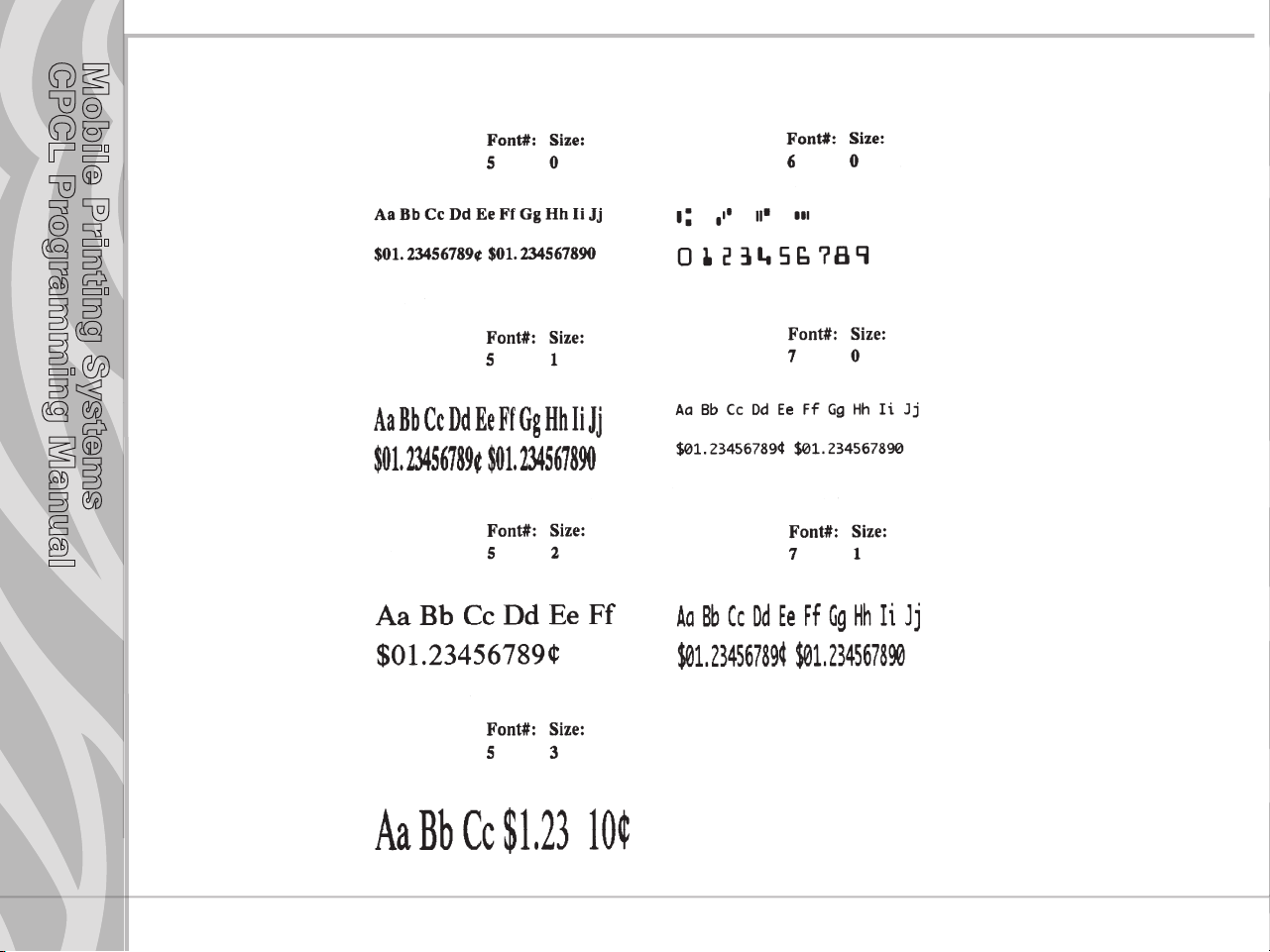
Resident Font Examples 3-1
Using Font Groups 3-6
SCAL ABLE TEXT 4-1
LINEAR BAR CODES 5-1
Introduction 5-1
Resident Linear Bar Code Samples 5-2
UPC and EAN/JAN Bar Codes 5-3
Code 39 or Code 3 of 9 Bar Codes 5-6
Code 93 or Code 9 of 3 Bar Codes 5-8
Interleaved 2 of 5 Bar Codes 5-9
Code 128 and the UCC-128 Shipping Standard 5-10
Codabar 5-11
MSI Plessey Bar Codes 5-12
Postnet and Facing Identification Marks 5-13
Bar Code Commands 5-14
REDUCED SPACE SYMBOLOGY AND COMPOSITE SYMBOLS 5-20
RSS SYMBOLOGY 5-20
continued
Page 4

Index
Mobile Printing Systems
CPCL Programming Manual
RSS Limited 5-20
RSS-14 5-20
RSS Expanded 5-21
RSS Stacked 5-21
RSS-Truncated 5-21
RSS-14 Stacked Omnidirectional 5-21
RSS/Composite Symbologies 5-21
Composite Code A atop RSS Limited: 5-22
Composite Code B atop Code 128 5-22
Composite Code-C atop Code 128 5-22
TWO DIMENSIONAL BARCODES 6-1
Introduction 6-1
PDF417 6-1
MaxiCode 6-1
QR Code 6-2
Two Dimensional Barcode Commands 6-2
GRAPHICS 7-1
ADVANCED COMMANDS 8-1
Using Format Files 8-25
MCR Commands 8-32
LINE PRINT MODE 9-1
Introduction 9-1
Special Commands Using the Utility Function 9-3
Special ASCII Characters 9-10
Tearing or Cutting the Paper 9-14
Designing a Receipt 9-17
ADVANCED UTILITIES 10-1
Magnetic Card Reader (MCR) Command 10-23
DENSO BHT COMMANDS 10-38
PRINTER ESCAPE COMMANDS 11-1
SET AND READ CODE COMMAND 11-1
Contents
pg. iv
continued
Page 5

Mobile Printing Systems
CPCL Programming Manual
Contents
pg. v
Index
STATUS/INFORMATION 11-2
USER LABEL COUNT 11-5
Power Off Command 11-6
WIRELESS NETWORK PRINTERS 12-1
Introduction 12-1
Network Printer Safety Consideration 12-1
Setting the IP Address for Network Printers 12-8
Network Printer Troubleshooting 12-10
Wireless LAN Report Example 12-11
Introduction: 13-1
Example 1: 13-1
Example 2: 13-5
Table 1: WML Tags used on QL and RW Series Printers 13-7
CONFIGURATION/CONTROL COMMANDS 14-1
Introduction 14-1
Command Format 14-1
Commands / Parameters 14-2
Bluetooth® Parameters 14-3
Comm Port Parameters 14-18
Device Parameters 14-20
Display Parameters 14-33
File Parameters 14-35
Printer Mechanism Parameters 14-39
Input Parameter 14-42
Media Parameters 14-46
Memory Parameters 14-49
Network Management Parameters 14-52
Setting Avalanche Parameters with CPCL 14-56
Odometer Parameters 14-64
Power Parameters 14-66
Test Function Parameters 14-77
Print Parameters 14-78
continued
Page 6

Index
Mobile Printing Systems
CPCL Programming Manual
Networking Parameters 14-80
Frequency Hopping Spread Spectum (FHSS) Radio Compatibility. 14-133
WLAN Parameters 14-133
wlan.associated 14-134
Roaming Commands 14-186
International Mode 14-189
RFID Parameters 14-190
USB Parameters 14-196
Zebra Printer Mirror Process 14-200
Internal Wired Parameters 14-209
Interface Parameters 14-232
PRINTER CONFIGURATION AND SETUP 15-1
Using Label Vista for Printer Configuration 15-1
Using Label Vista for Wireless Configuration 15-4
Power Management 15-4
Batch Files 15-6
INDEX Index-1
APPENDIX A- FREQUENTLY ASKED QUESTIONS A-1
APPENDIX B- INTERFACE CABLES A-3
APPENDIX C- CHARACTER TABLES A-9
APPENDIX D - FONT INFORMATION A-13
Font Names A-13
Font Heights A-13
Fixed-Width Fonts A-14
Proportional Width Fonts A-14
APPENDIX E-BAR CODE QUICK REFERENCE A-17
APPENDIX F - PRODUCT SUPPORT A-19
Media Supplies A-19
Maintenance Supplies A-19
Contact Us A-20
Contents
pg. vi
Page 7

Mobile Printing Systems
CPCL Programming Manual
INTRODUCTION
This manual details the various commands in the CPCL language which enable the programmer to utilize
the built in text, graphics, bar code printing and communications capabilities of Zebra mobile printers.
The following notation conventions are used throughout this manual:
{ } Required item
[ ] Optional item
( ) Abbreviated command
< > Literal item
A space character is used to delimit each field in a command line.
Many commands are accompanied by examples of the command in use. After the word “Input” in each
example, the set of commands are displayed followed by a sample printout (“Output”)resulting from the
printer processing those commands.
PROGRAMMING LANGUAGE EMULATION
Zebra Mobile Printers can emulate the EPL2™ and ZPL® programming languages used by other types of
Zebra printers. Some printers using emulation must be configured with more memory and have a special
emulation program loaded. For more information on the appropriate uses of these languages, refer to the
following language comparison chart:
Contents
pg. 1-1
continued
Page 8

Mobile Printing Systems
CPCL Programming Manual
Programming Language Recommendations
Language Native in Reccommended Use
CPCL
ZPL
(emulation available
on QL series,standard.
on QL plus, RW & MZ
Series)
EPL
(emulation available
on QL or Cameo
series and standard
on RW , QL plus &
MZ series)
Note: QL Plus and RW printers have EPL and ZPL emulation built into their operating system. See the “device.languages” command under the “Device
Parameters” topic in Section 14 for more information on setting programming languages with these products.
QL, RW MZ, EZ320 and
older Comtec® models
PA/PT Series mobile,
printers, Zebra
High Per formance/
Industrial/Commercial
printers,R-140 RFID
printer,LP/TLP 2844-Z and
PAX applicator printers
Zebra Desktops, R402(RFID
printer), TR 220, PS 21xx
and PS 4000 series print
systems
• In new installations of mobile printers, where CPCL is easily
integrated into the host application
• When older Comtec models are being upgraded- so that the
customer can use existing application without code modifications
• When an installation already uses ZPL as a standard language and
needs to maintain a consistant language for all thermal printers.
• When certain printer functions are not available in CPCL or EPL,
such as: (ZBI, Datamatrix, Code 11, Micro PDF)
• When replacing a PA/PT 40x, or another Zebra printer using ZPL,
with a Zebra mobile printer
• When an installation already uses EPL as a standard language and
needs to maintain a consistant language for all thermal printers.
•If you are replacing Eltron Transport or Xport mobile printers, a Zebra
mobile with an EPL emulation will ease the transition.
Contents
pg. 1-2
Page 9

Mobile Printing Systems
CPCL Programming Manual
GETTING PRINTER INFORMATION
The printer can produce a report containing information about the application resident in printer
memory. A report similar to the example printouts shown on the following pages can be obtained from
your printer by doing the following:
1. Turn the printer OFF.
2 While holding the FEED key down, turn the printer ON.
3 When printing begins, release the FEED key.
The printer prints a line of interlocking “x” characters and then produces two reports. The first report
indicates the printer model, ROM version, serial number, baud rate, etc.
The second report contains application information. The last digits in the application number indicate
the software version.(e.g. “Software: HTLK40d” indicates a software version of 40.) If no second report
appears, there is no application loaded.
The Wireless Communications report will appear if a Short Range Radio (SRRF), infrared (IrDA) or
wireless LAN (RF LAN) option has been installed in the printer. If no wireless options are installed, the
Wireless Communications Section will consist of a blank line.
The RF LAN Information section will only appear on Network Printers (units equipped with a WLAN
card). Network printers are covered in detail in Section 12 of this manual.
The Label section shown in the second report reports the maximum size label that can be printed, based
on a printer resolution of 203 dots/inch (8 dots/mm).
In the example, the Label Height is 65535 dots, which means for a label width of 384 dots (1.88 inches
or 48 mm), you can print labels up to 32.2 inches (8191 mm) long. Reducing the label width results in a
corresponding increase in the maximum label length.
Contents
pg. 1-3
continued
Page 10
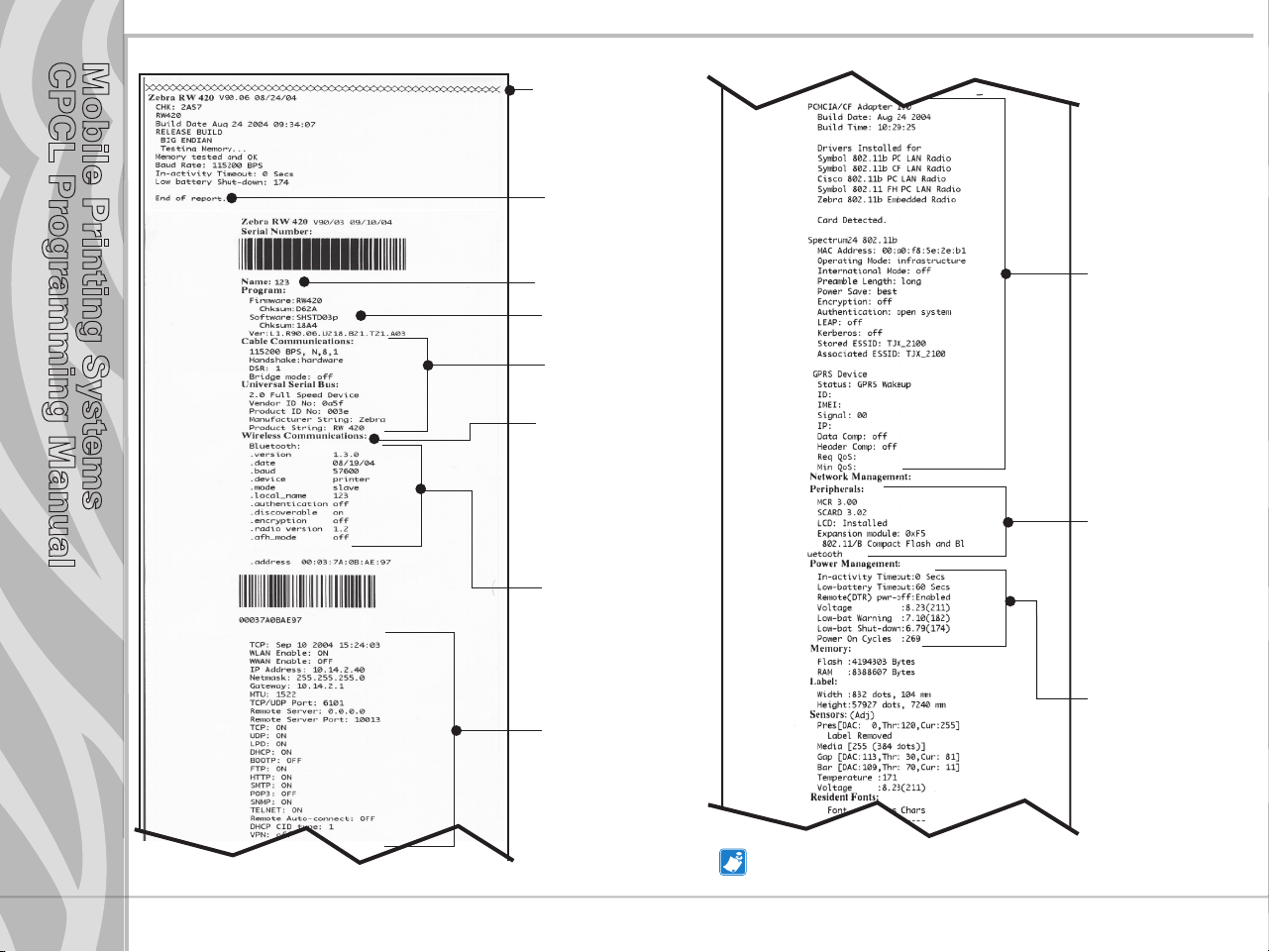
Getting Printer Information Example
Mobile Printing Systems
CPCL Programming Manual
Print Head Test
End of First Report
Unit Serial Number
Software and
Firmware installed
Settings for RS232 and
USB communications
via cable
Report appears only
on units with wireless
options installed.
Units with no wireless
options will print an
empty line and resume
printing
This example has
a Bluetooth radio
module installed.
Information on TCP/IP
and LAN addresses
and settings.
Information on any
installed 802.11x
wireless devices
In this example, an
802.11b WLAN card
has been detected.
List of peripherals
installed. In this
example the printer
has the Mag Card
and SmartCard
reader option,
and the wireless
expansion module
has an 802.11b and
Bluetooth wireless
module1.
List of power management settings.
Also includes a
count of the number
of times the unit has
been powered on.
Contents
pg. 1-4
Dual radio units as illustrated above are available only
on models RW 420, QL 220 plus and QL 420 plus.
continued
Page 11

Getting Printer Information Example (continued)
Mobile Printing Systems
CPCL Programming Manual
Flash Memory Size
RAM Size
Maximum Label Size
Resident Fonts
Contents
pg. 1-5
(my 2010.CPF)
(my 2020.CPF)
myfont .FNT
myfont2 .FNT
myfont3 .FNT
my_2010 .CPF
my_2020 .CPF
Resident Pre-scaled Fonts
Files Loaded in Printer Memory (will
include Pre-scaled or Scalable Fonts)
Amount of Free Memory Available
End of Conguration
Instructions on entering
Communications Diagnostics
(Dump) Mode. Refer to page 6
of this section
Page 12

Mobile Printing Systems
CPCL Programming Manual
Communications Diagnostics Mode
To aid the user in diagnosing communications problems, the printer features a Communications
Diagnostics Mode (Dump Mode). In the dump mode, the printer will print the ASCII hex codes of the data
sent to it, and their text representation (or the period ‘.’, if not a printable character). As a test of the printer
the “ALL CHRS.LBL” file on the MPU disk may be sent.
To enter Communications Diagnostics Mode:
1. Turn the printer OFF.
2. Hold FEED key down.
3. Turn the printer ON.
4. Release FEED key when printer starts printing the diagnostics.
5. At the end of 2nd diagnostics report, the printer will print: “Press FEED key to enter DUMP mode”.
6. Now press the FEED key. The printer will print: “Entering DUMP mode”.
Note: If the FEED key is not pressed within 3 seconds, the printer will print “DUMP mode not entered” and will resume normal
operation.
7. At this point, the printer is in DUMP mode and will print the ASCII hex codes of the data sent to it, and
their text representation (or “.” if not a printable character).
Additionally, a file with a “.dmp” extension containing the ASCII information will be created
and stored in the printer’s memory. It can be viewed, “cloned” or deleted using the Label Vista
application. (Refer to pg. P1-8 and the Label Vista documentation for more information.)
To cancel Communications Diagnostics Mode:
Contents
pg. 1-6
1. Turn the printer OFF.
2. Wait 5 seconds.
3. Turn the printer ON.
Page 13
Mobile Printing Systems
CPCL Programming Manual
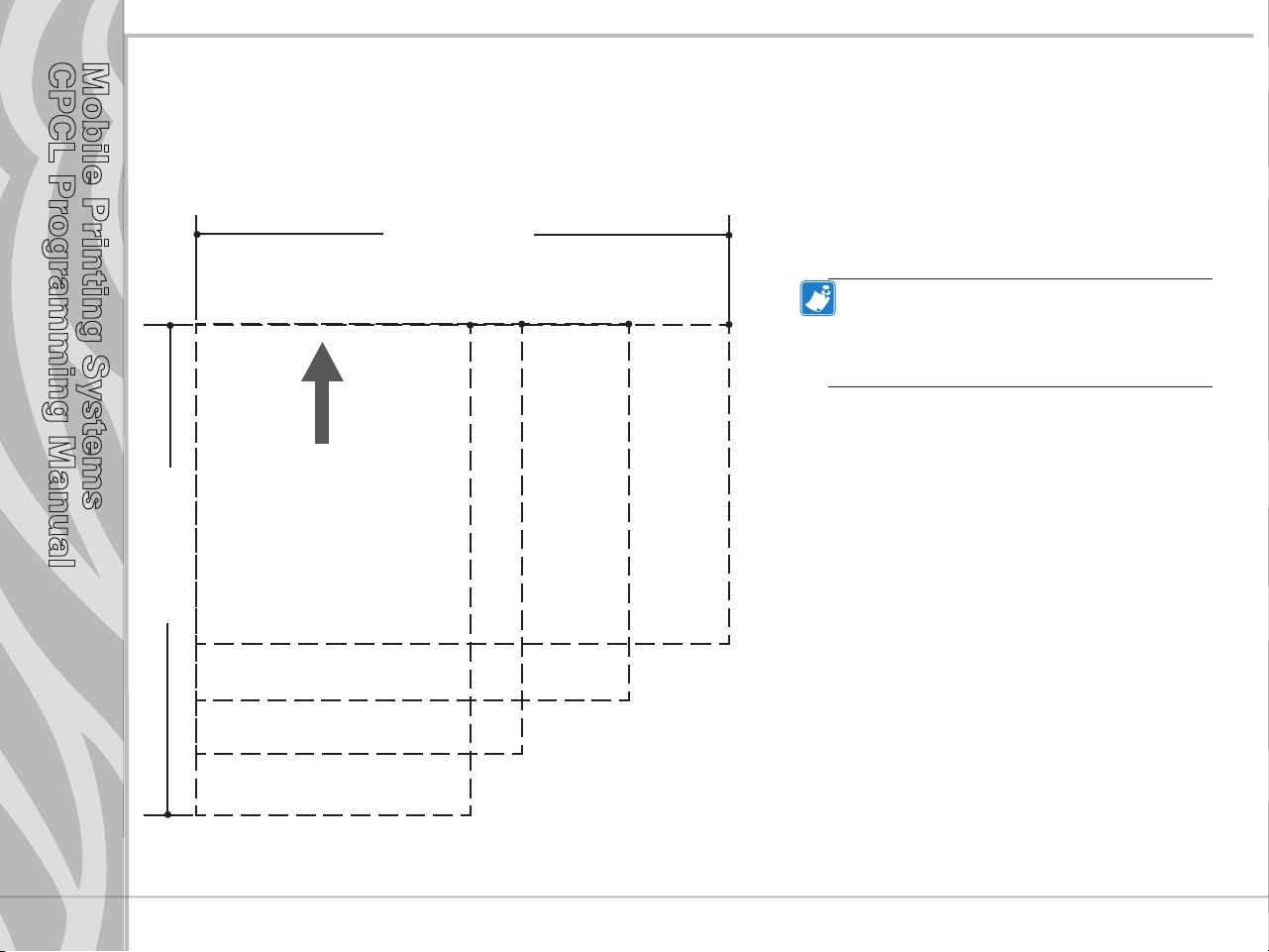
LABEL COORDINATE SYSTEM
The x and y coordinates are expressed here in terms of dots. Coordinates in ( ) are for 200 dot per inch
printers. On 200 d.p.i. printers, 8 dots (either horizontally or vertically) equal 1 millimeter and 203 dots
equate approximately to 1 inch.
Coordinates in [ ] are for 300 dot per inch
printers. On 300 d.p.i. printers 12 dots
Label Width
equal 1 millimeter, and 305 dots equate
approximately to 1 inch.
Notes: 1. Coordinates refer to the actual printing
area of the printers.
(0,0)
(575, 0)
(383, 0)
[574,0]
(447, 0)
[670,0]
[862,0]
(831, 0)
[1246,0]
2. ”y” =the available label height which can
vary with the resident application. (See Getting
Printer Information, Page 3 of this section.)
Contents
pg. 1-7
2” Printer
2.25” Printer
Label Height
Print Direction
(447, y)
[670,y]
(383, y)
[574,y]
3” Printer
(575, y)
[862,y]
4” Printer
(831,y)
[1246,y]
Page 14
Mobile Printing Systems
CPCL Programming Manual
LABEL VISTA™
Label Vista is a stand-alone program for the Windows® operating system that allows users with little
or no programming background to design labels which can be printed on certain model Zebra portable
printers. It combines an intuitive graphically based user environment with powerful, but easily mastered,
editing tools.
Label Vista allows the creation of printable, fixed-size (pre-scaled) fonts derived from an included library
of TrueType™ fonts, which greatly enhances the versatility of this program.
In addition, Label Vista allows the easy creation of format files which can remain resident in the printer
and be merged with variable data files sent from the host. This provides a very efficient method of
printing labels that have a mixture of data fields that change from label to label and elements that remain
constant. Refer to Section 8 of this Manual for more information on format files.
Label Vista also provides a powerful set of diagnostics tools. It is recommended that the Label Vista
documentation package be consulted for a more detailed description of the printer diagnostics available in
this program.
Label Vista utilizes a subset of the full CPCL Programming Language described in this manual. Files
created in Label Vista are fully compatible with any other label files created using the complete set of
Mobile Printer commands.
Label Vista requires a personal computer, running Windows 95 or later. A system with the minimum
configuration to run Windows 95 will have sufficient memory to run Label Vista.
Note: Label Vista has proven to be compatible with Windows XP in informal testing, however, compatibility problems with certain
unusual combinations of hardware and software may arise.
Contents
pg. 1-8
Page 15
Mobile Printing Systems
CPCL Programming Manual
PRINTER COMMANDS
A label file always begins with the “!” character followed by an “x” offset parameter, “x” and “y” axis
resolutions, a label length and finally a quantity of labels to print. The line containing these parameters is
referred to as the Command Start Line.
A label file always begins with the Command Start Line and ends with the “PRINT” command. The
commands that build specific labels are placed between these two commands.
A space character is used to delimit each field in a command line.
Note: Every line in the command session must be terminated with both carriage-return and line-feed characters. All Printer
Commands must be in uppercase characters ONLY.
Section 2
Printer
Commands
pg. 2-1
continued
Page 16
Mobile Printing Systems
CPCL Programming Manual
Printer Commands
Format:
<!> {oset} <200> <200> {height} {qty}
where:
<!>: Use ‘!’ to begin a control session.
{offset}:The horizontal offset for the entire label. This value causes all fields to be offset horizontally
by the specified number of UNITS.
<200>:Horizontal resolution (in dots-per-inch).
<200>:Vertical resolution (in dots-per-inch).
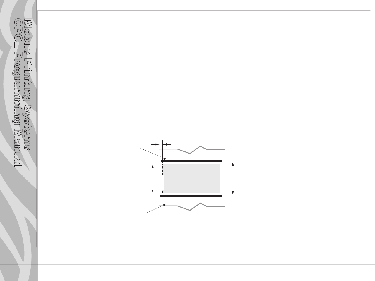
{height}:The maximum height of the label.
The maximum label height is calculated by measuring from the bottom of the first black bar
(or label gap) to the top of the next black bar (or label gap). Then 1/16” [1.5mm] is subtracted
from this distance to obtain the maximum height. (In dots: subtract 12 dots on 203 d.p.i
printers; 18 dots on 306 d.p.i. printers)
st
1
black bar or gap
Section 2
Printer
Commands
pg. 2-2
Max. label height “d”=
“h” - .062” [1.5mm]
nd
2
black bar or gap
“h” = height
between black bars
{qty}: Quantity of labels to be printed. Maximum = 1024.
continued
Page 17
Mobile Printing Systems
CPCL Programming Manual
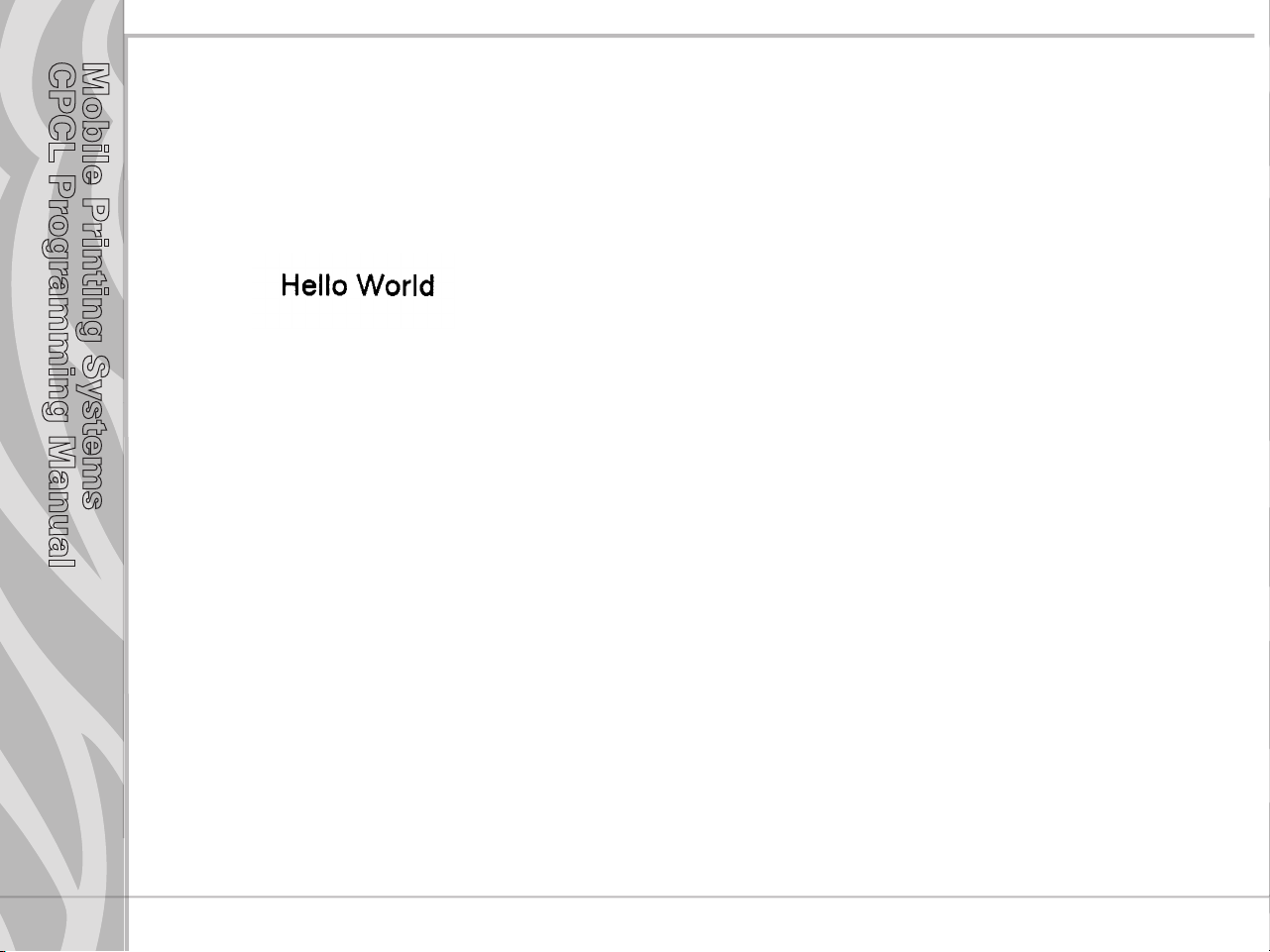
Printer Command Example
Input
! 0 200 200 210 1
TEXT 4 0 30 40 Hello World
FORM
PRINT
Output
PRINT Command
The PRINT command terminates and prints the file. This must always be the last command (except
when in Line Print Mode). Upon execution of the PRINT command, the printer will exit from a control
session. Be sure to terminate this and all commands with both carriage-return and line-feed characters.
Format:
{command}
where:
{command}: PRINT
Section 2
Printer
Commands
pg. 2-3
continued
Page 18

Mobile Printing Systems
CPCL Programming Manual
END Command
The END command properly terminates a command and executes it without printing.
Format: END
{command}
where:
{command}: END
Example:
REM Send a blank label
! 0 200 200 240 1\r\n
PAGE-WIDTH 240\r\n
BOX 0 0 200 200 10\r\n
BOX 50 50 220 220 10\r\n
END\r\n
ABORT Command
The ABORT command terminates a current control session without printing.
Format:
Section 2
Printer
Commands
pg. 2-4
{command}
where:
{command}: ABORT
Page 19
Mobile Printing Systems
CPCL Programming Manual
ENCODING Command
The ENCODING control command specifies the encoding of data sent to the printer.
Format:
{command} {name}
{command}: ENCODING
{name}: Choose from the following
“ASCII”
“UTF-8”
“GB18030”
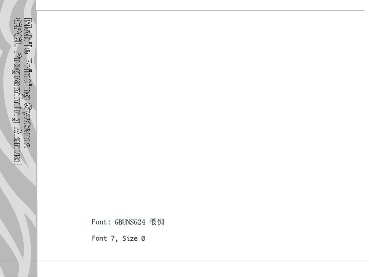
ENCODING Example
Input (ENCODING.LBL):
! 0 200 200 200 1
ENCODING GB18030
TEXT GBUNSG24.CPF 0 20 30 Font: GBUNSG24 ‚t‚u
ENCODING ASCII
TEXT 7 0 20 80 Font 7, Size 0
PRINT
Section 2
Printer
Commands
pg. 2-5
Output
Page 20

Mobile Printing Systems
CPCL Programming Manual
Section 2
Printer
Commands
pg. 2-6
FORM Command
The FORM command instructs the printer to feed to top of form after printing.
Format:
{command}
where:
{command}: FORM
In the following example, the printer will execute a form feed after the label is printed. See the SETFF
(set form feed) command in the section on designing receipts and lists for information on setting printer
behavior when the FORM command is executed.
Example
Input:
! 0 200 200 3 1
IN-CENTIMETERS
CENTER
TEXT 4 1 0 .5 Form Command
FORM
PRINT
JOURNAL Command
By default, the printer will check for correct media alignment if it encounters the eye-sense mark
(black horizontal bars on back of media) during a print cycle (LABEL mode). If necessary, the JOURNAL
command can be used to disable this automatic correction feature. The user’s program is responsible for
checking and assuring presence of paper in JOURNAL mode. Please refer to the status inquiry command
for details on checking for out-of-paper condition.
Format:
{command}
where:
{command}: JOURNAL
continued
Page 21

Mobile Printing Systems
CPCL Programming Manual
UNITS Commands
The units commands are used to specify a measurement system for all subsequent command fields in a
control session. Coordinates, widths, and heights for all control commands can be entered with precision
to four decimal places. By placing a units command immediately after the first line in a control session,
the specified measurement system will also apply to the offset and height fields. The printer measurement
system will default to dots until a units command is issued.
Format:
{command}
where:
{command}: Choose from the following:
IN-INCHES Measurement in inches.
IN-CENTIMETERS Measurement in centimeters.
IN-MILLIMETERS Measurement in millimeters.
IN-DOTS Measurement in dots.
Section 2
Printer
Commands
pg. 2-7
continued
Page 22
Mobile Printing Systems
CPCL Programming Manual
UNITS Examples
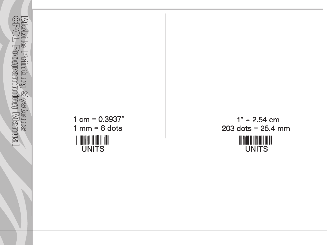
Input 1 :
! 0.3937 200 200 1 1
IN-INCHES
T 4 0 0 0 1 cm = 0.3937”
IN-DOTS
T 4 0 0 48 1 mm = 8 dots
B 128 1 1 48 16 112 UNITS
T 4 0 48 160 UNITS
FORM
PRINT
Input 2
! 0 200 200 2.54 1
IN-CENTIMETERS
T 4 0 1 0 1” = 2.54 cm
IN-MILLIMETERS
T 4 0 0 6 203 dots = 25.4 mm
B 128 0.125 1 6 12 14 UNITS
T 4 0 16 20 UNITS
FORM
PRINT
Section 2
Printer
Commands
pg. 2-8
Output 1:
Output 2
continued
Page 23
Mobile Printing Systems
CPCL Programming Manual
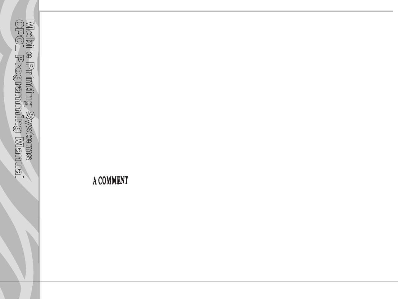
USING COMMENTS
Comments can be added between the first line of a command session and the “PRINT” command.
A comment is placed in the file by starting a line with the ‘;’ character in the first column. Any remaining
text to the end of the line will be ignored. Comments are illegal between the CONCAT and ENDCONCAT
commands.
Comments Example
Input:
! 0 200 200 25 1
IN-MILLIMETERS
JOURNAL
; Center justify text
CENTER
; Print the words ‘A COMMENT’
TEXT 5 1 0 5 A COMMENT
; Print the label and go to top of next form
FORM
PRINT
Output:
Section 2
Printer
Commands
pg. 2-9
continued
Page 24
Mobile Printing Systems
CPCL Programming Manual
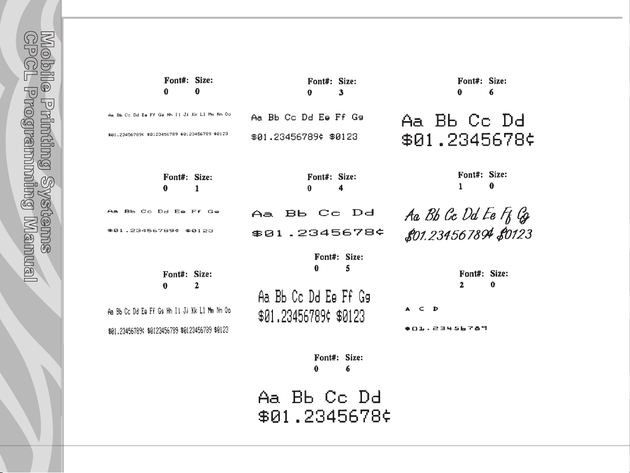
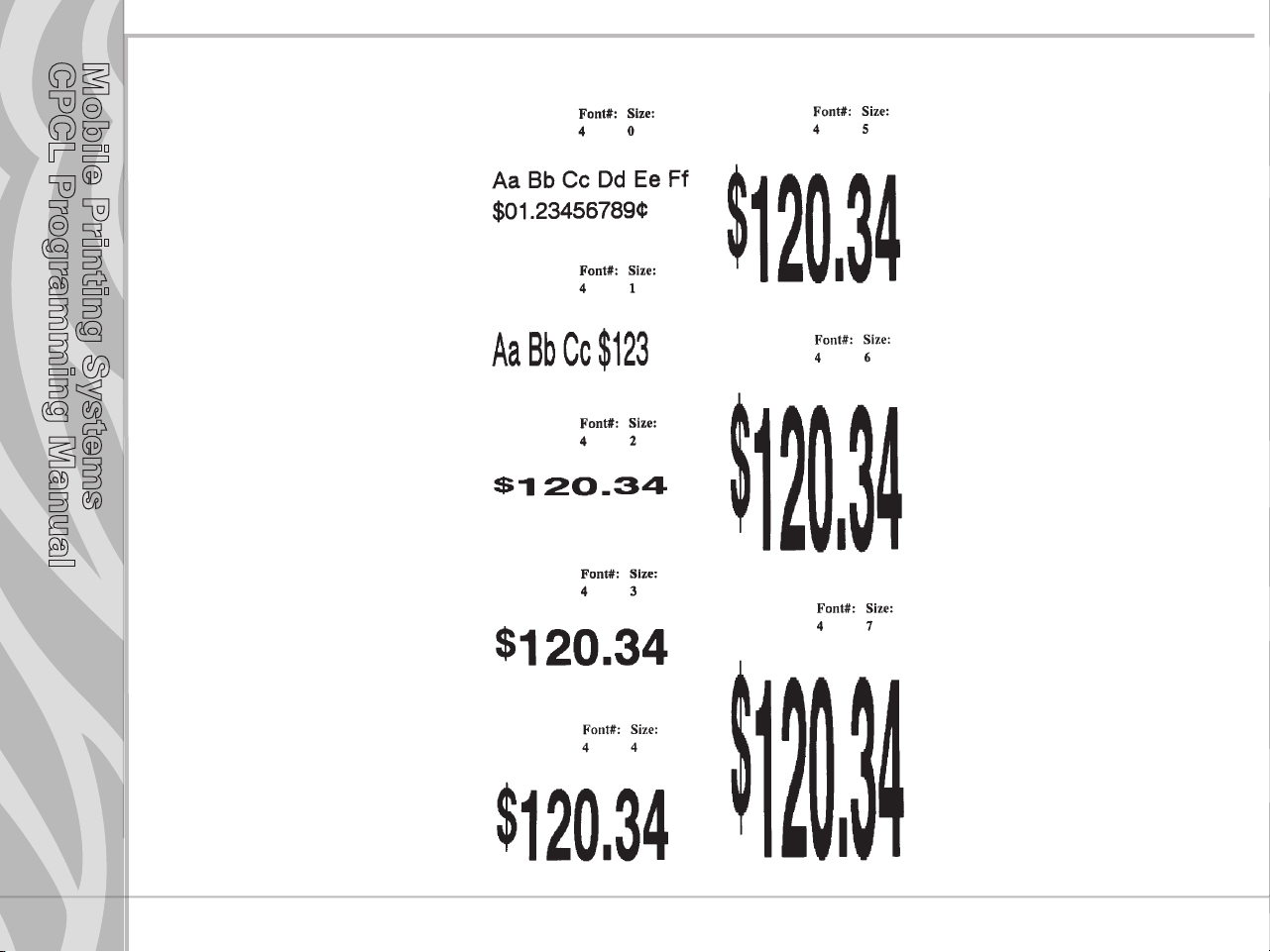
TEXT
Resident Font Examples
Section 3
Text
pg. 3-1
continued
Page 25
Mobile Printing Systems
CPCL Programming Manual
Resident Font Examples (continued)
Section 3
Text
pg. 3-2
continued
Page 26
Mobile Printing Systems
CPCL Programming Manual
Resident Font Examples (continued)
Section 3
Text
pg. 3-3
continued
Page 27
Mobile Printing Systems
CPCL Programming Manual
TEXT Commands
The TEXT command is used to place text on a label. This command and its variants control the specific
font number and size used, the location of the text on the label, and the orientation of this text. Standard
resident fonts can be rotated in 90˚ increments as shown in the example.
Format:
{command} {font} {size} {x} {y} {data}
where:
{command}: Choose from the following:
{command} Result
TEXT (or T) Prints text horizontally.
VTEXT (or VT) Prints text (vertically) rotated 90 degrees counterclockwise.
TEXT90 (or T90) (Same as VTEXT above.)
TEXT180 (or T180) Prints text (upside down) rotated 80 degrees counterclockwise.
TEXT270 (or T270) Prints text (vertically) rotated 270 degrees counterclockwise.
{font}: Name/number of the font.
{size}: Size identifier for the font.
{x}: Horizontal starting position.
{y}: Vertical starting position.
{data}: The text to be printed.
Section 3
Text
pg. 3-4
continued
Page 28
Mobile Printing Systems
CPCL Programming Manual
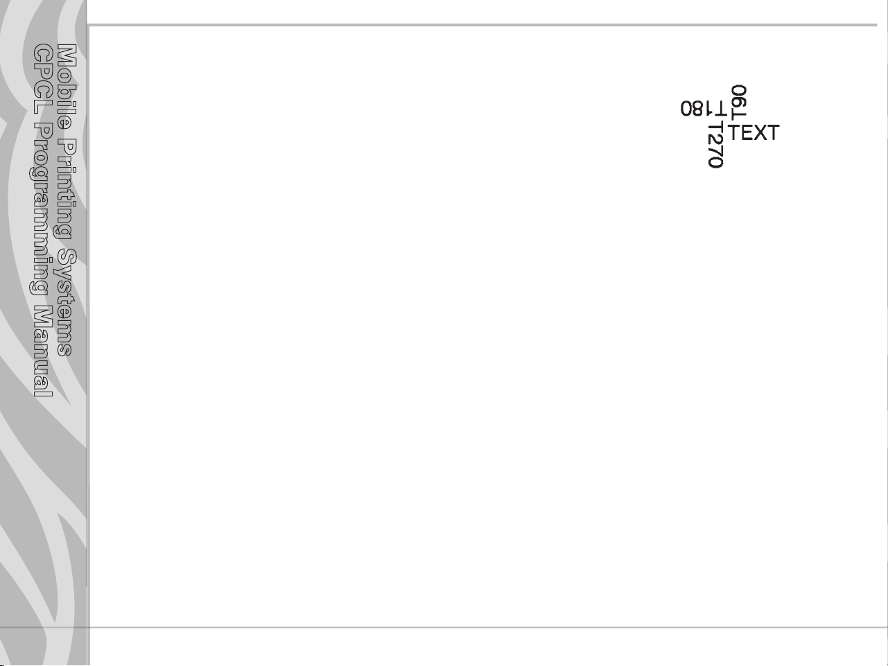
Example
Input:
! 0 200 200 210 1
TEXT 4 0 200 100 TEXT
TEXT90 4 0 200 100 T90
TEXT180 4 0 200 100 T180
TEXT270 4 0 200 100 T270
FORM
PRINT
Output:
Section 3
Text
pg. 3-5
continued
Page 29
Mobile Printing Systems
CPCL Programming Manual
Using Font Groups
FONT-GROUP (FG) Command
The FG command gives a user the ability to group up to 10 pre-scaled font files into a single group. A
user can later specify the font group in a TEXT command. If a font group is used in a text command, the
printer will use the largest font specified in the font group that will produce the required text data and
still remain within the available width of the label for the text. When specified in the TEXT command, the
{font} parameter is specified as FG, and the {size} parameter is specified as the {fg}. Note that a user can
also specify an FG command within a CONCAT/ENCONCAT command.
Format:
{command} {fg fn fs} [fn fs] ...
where:
{command}: FG
{fg}: Font group number. Up to 10 font groups can be specified. Valid font groups range from 0 to 9.
{fn}: Name/number of the font.
{fs}: Size identifier for the font.
NOTE: Up to 10 font number/font size pairs can be assigned to a font group.
Section 3
Text
pg. 3-6
continued
Page 30
Mobile Printing Systems
CPCL Programming Manual
Example
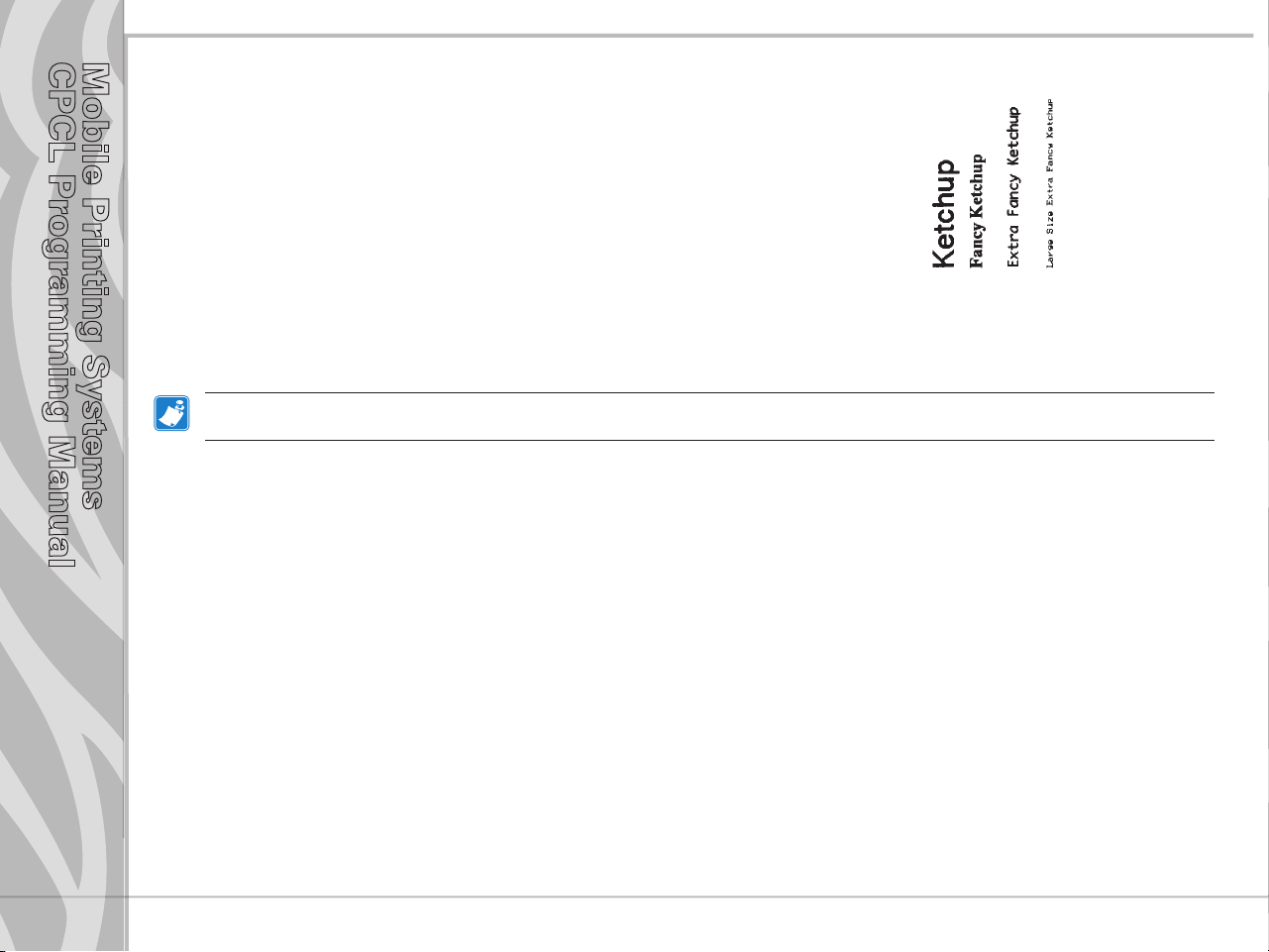
Input:
! 0 200 200 250 1
; Specify fonts 0-0, 7-0, 5-0, 4-0 as members
; of font group 3.
FG 3 0 0 7 0 5 0 4 0
VT FG 3 10 250 Ketchup
VT FG 3 70 250 Fancy Ketchup
VT FG 3 120 250 Extra Fancy Ketchup
VT FG 3 180 250 Large Size Extra Fancy Ketchup
FORM
PRINT
In this example, the descriptions will be printed with the largest font in the specied font group that is capable of tting the
requested text in a 250 dot label eld.
Output:
Section 3
Text
pg. 3-7
continued
Page 31

Mobile Printing Systems
CPCL Programming Manual
TEXT Concatenation Commands (CONCAT and VCONCAT)
Text concatenation allows you to assign different character styles to strings, printing them with uniform
spacing on the same text line. This command can be used in combination with scalable fonts. See
Scalable Concatenation Commands
Format:
{command} {x} {y} {font} {size} {offset} {data}
where:
{command}: Choose from the following:
CONCAT: Horizontal concatenation.
VCONCAT: Vertical concatenation.
{x}: Horizontal starting position.
{y}: Vertical starting position.
{font}: Name/number of the font.
{size}: Size identifier for the font.
{offset}: Unit-value to offset text from the starting position. Used to align individual text strings or
create superscript/subscript characters.
{data}: Text to be printed.
<ENDCONCAT>: Terminates concatenation.
“ “ “ “
{font} {size} {offset} {data} <ENDCONCAT>
Section 3
Text
pg. 3-8
continued
Page 32

Mobile Printing Systems
CPCL Programming Manual
Text Concatenation Example
Input:
! 0 200 200 210 1
CONCAT 75 75
4 2 5 $
4 3 0 12
4 2 5 34
ENDCONCAT
FORM
PRINT
Output:
Section 3
Text
pg. 3-9
continued
Page 33

Mobile Printing Systems
CPCL Programming Manual
MULTILINE ML Commands
MULTILINE (ML) allows you to print multiple lines of text using the same font and line-height.
Format:
{command} {height}
{text} {font} {size} {x} {y}
{data}
“
{data}
<ENDMULTILINE>
where:
{command}: MULTILINE (or ML)- Prints multiple lines of text.
{height}: Unit-height for each line of text.
{text}: Text command (TEXT, VTEXT, etc.).
{font}: Name/number of the font.
{size}: Size identifier for the font.
{x}: Horizontal starting position.
{y}: Vertical starting position.
{data}: Text to be printed.
<ENDMULTILINE> (or ENDML): Terminates MULTILINE.
Section 3
Text
pg. 3-10
continued
Page 34

Mobile Printing Systems
CPCL Programming Manual
ML Command Example
Input:
! 0 200 200 210 1
ML 47
TEXT 4 0 10 20
1st line of text
2nd line of text
:
Nth line of text
ENDML
FORM
PRINT
Output:
Section 3
Text
pg. 3-11
continued
Page 35

Mobile Printing Systems
CPCL Programming Manual
COUNT Command
The COUNT command is used for printing multiple labels where a numeric text field or numeric
data encoded in a bar code is to be incremented or decremented for each label. The TEXT/BARCODE
command string must contain this numeric data as the last characters of the string. The numeric data
portion can be up to 20 characters, and can be preceded by the ‘-’ sign. Incrementing or decrementing the
numeric data thru ‘0’ is not allowed. Leading zeros will be retained. Up to three COUNT commands can
be used in a label file.
The numeric data incremented/decremented is contained in the TEXT or BARCODE command that
immediately preceded the COUNT command.
Format:
{command} {numeric value}
where:
{command}: COUNT
{numeric value}: Any integer value up to 20 characters. The value can be preceded by a ‘-’ sign if decrementing of
the TEXT/BARCODE value is desired. Leading zeros will be retained in the output.
Section 3
Text
pg. 3-12
continued
Page 36

Mobile Printing Systems
CPCL Programming Manual
COUNT Command Example
Input:
! 0 200 200 210 3
; Print 3 labels
CENTER
TEXT 4 0 0 50 TESTING 001
COUNT 1
TEXT 7 0 0 100 Barcode Value is 123456789
COUNT -10
BARCODE 128 1 1 50 0 130 123456789
COUNT -10
FORM
PRINT
Output:
Section 3
Text
pg. 3-13
continued
Page 37

Mobile Printing Systems
CPCL Programming Manual
Section 3
Text
pg. 3-14
SETMAG Command
The SETMAG command magnifies a resident font to the magnification factor specified.
Format:
{command} {w} {h}
where:
{command}: SETMAG
{w}: Width magnification of the font. Valid magnifications are 1 thru 16.
{h}: Height magnification of the font. Valid magnifications are 1 thru 16.
NOTE: The SETMAG command stays in eect after printing a label. This means that the next label printed will use the most recently
set SETMAG values. To cancel any SETMAG values and allow the printer to use its default font sizes, use the SETMAG command
with magnications of 0,0.
SETMAG Command Example
Input:
! 0 200 200 210 1
CENTER
SETMAG 1 1
TEXT 0 0 0 10 Font 0-0 at SETMAG 1 1
SETMAG 1 2
TEXT 0 0 0 40 Font 0-0 at SETMAG 1 2
SETMAG 2 1
TEXT 0 0 0 80 Font 0-0 at SETMAG 2 1
SETMAG 2 2
TEXT 0 0 0 110 Font 0-0 at SETMAG 2 2
SETMAG 2 4
TEXT 0 0 0 145 Font 0-0 at SETMAG 2 4
; Restore default font sizes
SETMAG 0 0
FORM
PRINT
Output:
continued
Page 38

Mobile Printing Systems
CPCL Programming Manual
SCALABLE TEXT
Scalable text allows a user to print text at any point size. Point size can be specified for both the X and
Y directions to produce characters that are “stretched” in either their width or height. Point sizes specified
and text produced will print at 72 points equating to one inch (25.4mm).
The printer can contain scalable font files as part of the application, or scalable font files can be
downloaded to the printer using one of the utilities on the supplied disk. A scalable text file must be
present in your printer’s memory in order to use scalable text features.
SCALE-TEXT Commands
The SCALE-TEXT commands allow the user to specify the point size of both the width and height of the
font.
Format:
{command} {name} {width} {height} {x} {y} {data}
where:
{command}: SCALE-TEXT (or ST): Prints scaled text horizontally.
VSCALE-TEXT (or VST): Prints scaled text vertically.
{name}: Font name.
{width}: Font width (point size).
{height}: Font height (point size).
{x}: Horizontal starting position.
{y}: Vertical starting position.
{data}: Text to be printed.
Section 4
Scalable Text
pg. 4-1
continued
Page 39

Mobile Printing Systems
CPCL Programming Manual
SCALE-TEXT Example:
Input:
! 0 200 200 300 1
CENTER
; Print using x and y scales of 10 points
SCALE-TEXT PLL_LAT.CSF 10 10 0 10 10 POINT FONT
; Print using x scale of 20 points and y scale
; of 10 points
SCALE-TEXT PLL_LAT.CSF 20 10 0 80 WIDER FONT
; Print using x scale of 10 points and y scale
; of 20 points
SCALE-TEXT PLL_LAT.CSF 10 20 0 150 TALLER FONT
FORM
PRINT
Output:
Section 4
Scalable Text
pg. 4-2
continued
Page 40

Mobile Printing Systems
CPCL Programming Manual
SCALE-TO-FIT Commands
The SCALE-TO-FIT commands automatically calculate the scale in order to fit text inside a window.
Format:
{command} {name} {width} {height} {x} {y} {data}
where:
{command}: Choose from the following:
SCALE-TO-FIT (or STF): Prints scaled text horizontally.
VSCALE-TO-FIT (or VSTF): Prints scaled text vertically.
{name}: Font name.
{width}: Unit-width of the window.
{height}: Unit-height of the window.
{x}: Horizontal starting position.
{y}: Vertical starting position.
{data}: Text to be printed.
Section 4
Scalable Text
pg. 4-3
continued
Page 41

Mobile Printing Systems
CPCL Programming Manual
SCALE-TO-FIT Command Example
Input:
! 0 200 200 100 1
IN-MILLIMETERS
CENTER
; Fit a text string into an area 40mm wide by 10mm ; high
SCALE-TO-FIT PLL_LAT.CSF 40 10 0 10 SALE
; Fit a longer text string into the same 40mm wide ; by 10mm high area
SCALE-TO-FIT PLL_LAT.CSF 40 10 0 20 SALE PRICE
; Fit “SALE” text into a 40mm wide by 20mm high ; area
SCALE-TO-FIT PLL_LAT.CSF 40 20 0 30 SALE
FORM
PRINT
Output:
Section 4
Scalable Text
pg. 4-4
continued
Page 42

Mobile Printing Systems
CPCL Programming Manual
SCALABLE CONCATENATION Commands
Scalable concatenation allows you to assign different character styles to strings, printing them with
uniform spacing on the same text line. Both scalable and bitmap text can be combined between a
CONCAT/ENCONCAT command. See also Text Concatenation Commands
Format:
{command} {x} {y}
<ST> {name} {width} {height} {offset} {data}
“ “ “ “ “ “
<ST> {name} {width} {height} {offset} {data}
<ENDCONCAT>
where:
{command}: Choose from the following:
CONCAT: Horizontal concatenation.
VCONCAT: Vertical concatenation.
{x}: Horizontal starting position.
{y}: Vertical starting position.
{name}: Font name.
{width}: Font width point size.
{height}: Font height point size.
{offset}: Unit-value to offset text from the starting position. Used to align individual text strings
or create superscript/subscript characters.
{data}: Text to be printed.
<ENDCONCAT>: Terminates concatenation.
Section 4
Scalable Text
pg. 4-5
continued
Page 43

Mobile Printing Systems
CPCL Programming Manual
SCALABLE CONCATENATION Command Example
Input:
! 0 200 200 210 1
CENTER
; Concatenate 3 scalable font strings and 1
; Resident font string
CONCAT 0 20
4 1 0 2/
ST PLL_LAT.CSF 20 20 15 $
ST PLL_LAT.CSF 40 40 0 22
ST PLL_LAT.CSF 20 20 0 99
ENDCONCAT
FORM
PRINT
Output:
Section 4
Scalable Text
pg. 4-6
continued
Page 44

Mobile Printing Systems
CPCL Programming Manual
ROTATE Command
ROTATE commands are used to rotate all subsequent scalable text fields at a specified angle. Rotation
direction is counter-clockwise about the center point of the text. This rotation remains in effect until
another ROTATE command is issued. Default angle is zero degrees.
Format:
{command} {angle}
where:
{command}: ROTATE (or R): Rotates scalable fonts.
{angle}: Degree of rotation (ccw).
ROTATE Command Example
Input:
! 0 200 200 440 1
CENTER
TEXT 4 1 0 50 Rotate Strings
ROTATE 45
CONCAT 50 300
ST PLL_LAT.CSF 20 20 20 $
ST PLL_LAT.CSF 40 40 0 22
ST PLL_LAT.CSF 20 20 0 99
ENDCONCAT
FORM
PRINT
Output:
Section 4
Scalable Text
pg. 4-7
continued
Page 45

Mobile Printing Systems
CPCL Programming Manual
LINEAR BAR CODES
Introduction
Bar codes allow easy implementation of automated identification, cataloging and processing of almost
any object. They have been successfully used on items ranging in size from boxcars to bumblebees.
This overview of bar code symbologies will help when programming Zebra mobile printers and/or
designing labels with Label Vista software.
If you plan to create software using these bar codes, we recommend ordering the uniform symbology
specification from AIM or the UCC to determine the uses and limitations pertaining to that type of bar
code. The information in this document is in no way complete.
The following discussions contain basic information and some suggested applications for each type of
bar code. The quick reference table in Appendix E lists specific data for each bar code in one location.
All the information on ideal widths and ratios comes directly from the uniform symbology specification.
Please note that all measurements contained in this document are in printer dots. On 200 dot per inch
(d.p.i.) printers, one dot is equal to 0.005” or 0.13 millimeters, on 300 d.p.i. printers one dot is equal to
0.003” or 0.07 millimeters.
Section 5
Linear Bar
Codes
pg. 5-1
continued
Page 46

Mobile Printing Systems
CPCL Programming Manual
Resident Linear Bar Code Samples
UPC-A UPC-E
EAN-13 EAN-8
EAN Plus2 Extender EAN Plus5 Extender
Code 39 Code 93
Interleaved 2 of 5 Code 128
Section 5
Linear Bar
Codes
pg. 5-2
UCC EAN 128 Codabar
Plessy Postnet
Page 47

Mobile Printing Systems
CPCL Programming Manual
UPC and EAN/JAN Bar Codes
UPC and EAN/JAN bar codes are typically used for marking products with a unique code used to look
up prices and to track inventories of goods sold. They are also used for store coupons, periodicals, and
paperback books. UPC and EAN/JAN bar codes are generally rectangular, contain a fixed amount of data,
and in most cases are accompanied by human readable text printed below them. For best results, this text
should be an OCR-A (resident font 2), a sans serif font (resident font 7) or an OCR-B font.
The first number in the UPC/EAN bar code is the number system character. The specification lists use of
characters 0 through 9 as follows.
0 Regular UPC codes (UPC-A and UPC-E)
1 Reserved
2 Random weight items, like store packaged meat. (UPC-A only)
3 National Drug Code and National Health Related Items Code in current 10-digit code length (UPC-A
only)*
4 In-store marking of non food items without code format restriction and with check digit protection
(UPC-A only)
5 Coupons (UPC-A only)
6 Regular UPC codes (UPC-A only)
7 Regular UPC codes (UPC-A only)
8 Reserved
9 Reserved
* Number system 3 has the following note in the specication. “…the symbol is not aected by the various internal
structures possible with the NDC or HRI codes.” The users should determine what eect this statement may have on their
program. It will not change how bar codes are printed.
Section 5
Linear Bar
Codes
pg. 5-3
The checksum is the last number in the bar code and can be used to make certain that the bar code is
decoded properly. This digit is automatically calculated by the printer. The UPC bar code specification
has the full instructions for calculating this checksum. The methodology is as follows:
For this example, the bar code will be 01234567890.
continued
Page 48

Mobile Printing Systems
CPCL Programming Manual
Section 5
Linear Bar
Codes
pg. 5-4
Step 1: Starting at the left, including the number system character, add up all the numbers in the ODD
positions. (0 + 2+ 4 + 6 + 8 + 0 = 20)
Step 2: Multiply this sum by 3. (20 x 3 = 60)
Step 3: Starting at the left again, add up all the numbers in the EVEN positions. (1 + 3 + 5 + 7 + 9 = 25).
Step 4: Add the results from step 2 and step 3. (60 + 25 = 85)
Step 5: The checksum is the smallest number when added to step 4 will equal a multiple of ten. In our
example: 85 + 5 = 90, which is a multiple of 10. Therefore, the check digit should be 5. It is called a
modulo checksum because you take the modulo, or remainder, of the sum. For the programmers, it
is:
10 - (85 mod 10) = the checksum.
UPC-A and EAN13 bar codes can be created with and without a checksum supplied. If the programmer
supplies a checksum digit, the printer will create the bar code with that check digit, even if it is incorrect.
Most laser scanning devices will not be able to decode the bar code if the check digit is incorrect,
UPC-E bar codes, useful for small items like candy and gum, are created through the method of “zero
suppression.” For example, if you were to encode 01000000567, the resulting bar code would be a
compressed bar code that only contains the data, the compression scheme, and the checksum without all
the extra zeros. For our example, the bar code would decode to 1056707. Please refer to the UPC Symbol
Specification Manual from the Uniform Code Council for more information on zero suppression.
UPC-E and EAN8 bar codes have a few restrictions. First, the number system character must be set to
0. Number systems 1 through 9 do not support UPC-E and EAN8 bar codes and may not be decoded by
a laser scanning device. In case your application requires it, the number system may be set to something
other than 0. Second, if the programmer supplies a checksum digit, the printer will create the bar code
with that check digit, even if it is incorrect. If the check digit is incorrect, most laser scanning devices will
not be able to decode the bar code. Therefore, the programmer may send six digits (no number system,
no checksum), seven digits (number system, no checksum), or eight digits (number system and checksum)
and create a bar code.
Plus 2 and plus 5 bar code extensions are only used for periodicals and paperback books. Specifically,
the bar code specification states that the plus 2 extension should only be used for a periodical issue
number. The plus 2 and plus 5 extensions do not contain any checksum according to the bar code
continued
Page 49

Mobile Printing Systems
CPCL Programming Manual
specification.
To create an extended bar code, place a space between the data that should go into the UPC/EAN bar
code and the data that should go into the extension. You can also use the PLUS2 and PLUS5 bar code
types to create the extension separately. Remember to leave ample space (about 9 times the ratio)
between the UPC/EAN bar code and the extension.
UPC/EAN Specications
Bar Code Symbology
UPC-A UPCA 11 or 12 digits 0-9 only 2:1 2 mod 10
UPC-A plus 2 UPCA 2 13 digits 0-9 only 2:1 2 mod 10
UPC-A plus 5 UPCA5 16 digits 0-9 only 2:1 2 mod 10
UPC- E UPCE 6, 7 or 11 digits 0-9 only 2:1 2 mod 10
UPC- E plus 2 UPCE2 8 or 13 digits 0-9 only 2:1 2 mod 10
UPC- E plus 5 UPCE5 11 or 16 digits 0-9 only 2:1 2 mod 10
EAN/JAN-13 EAN13 12 or 13 digits 0-9 only 2:1 2 mod 10
EAN/JAN-13 plus 2 EAN132 14 digits 0-9 only 2:1 2 (EAN13)
EAN/JAN-13 plus 5 EAN135 17 digits 0-9 only 2:1 2 (EAN13)
EAN/JAN-8 EAN8 6, 7 or 8 digits 0-9 only 2:1 2 mod 10
EAN/JAN-8 plus 2 EAN82 9 digits 0-9 only 2:1 2 mod 10 (EAN8)
EAN/JAN-8 plus 5 EAN85 12 digits 0-9 only 2:1 2 mod 10 (EAN8)
Bar
CodeType
Input Length Characters
Ideal Wide/
NarrowRatio
Ideal Narrow
Dot Width
Checksum
Calculation
Section 5
Linear Bar
Codes
pg. 5-5
continued
Page 50

Mobile Printing Systems
CPCL Programming Manual
Code 39 or Code 3 of 9 Bar Codes
The Code 39 bar code is used for many applications including inventories, hospital applications, or any
other place where the code length may change between items being scanned (e.g. a bar code stating
there were 420 pieces in one box and 20004 pieces in another box would have a different physical length).
This bar code can use the characters 0 through 9, A through Z, ‘-’ (dash), “.” (period), space, “$” (dollar
sign), “/”(forward slash), “+” (plus) and “%” (percent). There is also a special character called “S/S” used
as a start/ stop character. The F39 and F39C types allow the use of carriage return, line feed, and null
characters.
The checksum for this bar code is located as the last (or least significant) digit of the decoded bar code.
To assure data integrity in your application, use a bar code with a checksum. The printer will automatically
supply this digit if the user selects a 39C or a F39C bar code.
Check Character Numerical Value Table
Char Value Char Value Char Value Char Value
0 0 C 12 O 24 - 36
1 1 D 13 P 25 . 37
2 2 E 14 Q 26
3 3 F 15 R 27 $ 39
4 4 G 16 S 28 / 40
5 5 H 17 T 29 + 41
6 6 I 18 U 30 % 42
7 7 J 19 V 31 $ (full) 43*
8 8 K 20 W 32 % (full) 44*
9 9 L 21 X 33 /(full) 45*
A 10 M 22 Y 34 + (full) 46*
B 11 N 23 Z 35
SPACE
38
Section 5
Linear Bar
Codes
pg. 5-6
* Full represents F39 or F39C for Full ASCII
continued
Page 51

Mobile Printing Systems
CPCL Programming Manual
Refer to the full bar code symbology specification for complete information on checksum calculation.
For a short example, take an example bar code with the data “CODE 39” .
Step 1: Assign a value to each character per the Character Numerical Value Table above . C=12, O=24,
D=13, E=14, space = 38, 3=3, 9=9.
Step 2: Add the values 12+24+13+14+38+3+9=113.
Step 3: Divide this number by 43. The remainder or modulo, 27, is the checksum.
Step 4: Referring to the table, 27 is the character R. Therefore, the checksum in the bar code should be
R. The final code reads “CODE 39R” when it is decoded.
Code 39 (3 of 9) Specications
Section 5
Linear Bar
Codes
pg. 5-7
Bar Code
Symbology
Code 39
Bar Code
Type
39 Variable Refer text 2.5:1 2 none
39C Variable Refer text 2.5:1 2 mod 43
F39 Variable Refer text 2.5:1 2 none
F39C Variable Refer text 2.5:1 2 mod 43
Input Length Characters
Ideal Wide/
Narrow
Ratio
Ideal Narow
Dot Width
Checksum
Calculation
continued
Page 52

Mobile Printing Systems
CPCL Programming Manual
Code 93 or Code 9 of 3 Bar Codes
The Code 93 bar code is used for applications that require heavy error checking capabilities. To
accomplish this, the Code 93 bar code contains two separate error checking checksums that are
automatically calculated and placed into the bar code. This bar code is used for inventories, hospital
applications, or any other place where the length may change between items being scanned. (See Code
39 above.) This bar code type can use the entire ASCII 128 character set. It is useful for encoding data and
phrases like “Code 93”.
The two checksums in this bar code are located as the last and second to last characters in the decoded
bar code. Code 93 has a complex checksum calculation. Please see the bar code symbology specification
for information on how to create and decode this checksum. Please also note that the bar code symbology
specification does not state any ideal values for the ratio and the width of the narrow bar.
Code 93 Specications
Section 5
Linear Bar
Codes
pg. 5-8
Bar Code
Symbology
Code 93 93 Variable 128 ASCII 1.5:1 1 two mod 47
Bar Code
Type
Input Length Characters Ideal Wide/
Narrow Ratio
Ideal Narow
Dot Width
Checksum
Calculation
continued
Page 53

Mobile Printing Systems
CPCL Programming Manual
Interleaved 2 of 5 Bar Codes
The Interleaved 2 of 5 (or ITF) bar code is used for applications that have a fixed data length for all
items scanned. A date, telephone number, or a SKU of fixed length would be a good application for
this bar code. The symbology specification states that a ITF bar code may be partially decoded without
any recognizable difference. Therefore, to prevent this problem, you must keep the length of data to
a constant and perform an error checking routine on the decoding program to determine if the data is
correct.
Only the digits 0-9 can be encoded, and there should be an even number of digits in the data. If there is
an odd number of digits, the printer will automatically insert a zero (0) at the beginning of the bar code.
There are two bar code varieties with a checksum: Interleaved 2 of 5 “with checksum” and German Post
Code. German Post Code has fixed length – either 12 or 14 characters (including checksum).
Here is an example how to calculate modulo 10 checksum:
Step 1: To calculate the checksum, first ensure that you are starting with an odd number of digits in the
data. If not, add a zero (0) to the beginning of the data.
Step 2: Multiply every other digit by 3, and add up the numbers. So, if your data was “43827” your
calculation should be (4 x 3) + 3 + (8 x 3) + 2 + (7 x 3) = 62.
Step 3: Divide this number by 10, resulting in 6 with a remainder of 2. Subtract the remainder from 10.
In our example, 10 - 2 = 8. The checksum is this final number, 8. Append this to the end of your data.
Note that if the remainder was a zero, your checksum should be zero.
Interleaved 2 of 5 Specications
Section 5
Linear Bar
Codes
pg. 5-9
Bar Code
Symbology
Interleaved 2 of 5 I2OF5 Varies 0-9 only 2.5:1 2 See text
Interleaved 2 of 5
with checksum
German Post
Code
Bar Code
Type
I2OF5C Varies 0-9 only 2.5:1 2 See text
I2OF5G 11, 12,13 or 14 0-9 only 2.5:1 2 mod 10, weights 4,9
Input Length Characters Ideal Wide/
Narrow Ratio
Ideal Narrow
Dot Width
Checksum Calculation
continued
Page 54

Mobile Printing Systems
CPCL Programming Manual
Code 128 and the UCC-128 Shipping Standard
Code 128 is used for applications that need to contain a large amount of data such as shipping
applications, marking blood donations, and any other application that can vary in length between bar
codes being scanned. The bar code also contains a checksum as the last character in the code which
ensures that data remains intact.
Code 128 can use the entire ASCII 128 character set as well as other subsets available in the universal
symbology specification. The three start and stop characters determine which character set to use. The
checksum for this bar code is located immediately before the stop character. The bar code symbology
specification contains all the information on calculating this checksum. For a short example, we desire to
encode “BAR128” in a bar code. We will use “A” as our start and stop character in this example.
Step 1: The symbology specification assigns a numerical value for each character. Find the values of all
the characters in the data.
Step 2: Add the value of the start character and all the data characters multiplied by its position in the
bar code. For our example, the calculation would be 103 + (34 x 1) + (32 x 2) + (50x 3) + (17x 4) +
(18x 5) + (24 x 6) = 672.
Step 3: Divide this number by 103. The remainder or modulo, 54, is the checksum. The character that
assigned to 54 in the specification is “V”. Our final code will look like “ABAR128V” where “A” is the
start character, “BAR128” is the data, and “V” is the checksum.
The UCC-128 Shipping Standard is part of a document called Application Standard for Shipping
Container Codes available from the Uniform Code Council. This 90-page guide contains the entire
specification on marking any shipment sent anywhere in the United States. Seventeen pages are dedicated
to the technical considerations of using, placing, and printing these bar codes. We highly recommend
getting this information if your application involves shipping.
Section 5
Linear Bar
Codes
pg. 5-10
Code 128/ UCC-128 Specications
Bar Code
Symbology
Code 128 /A/B/C/
Auto
UCC-128Std. UCCE AN 16 Refer tex t Refer tex t N/A 2 mod 103
Bar Code
Type
128 Variable Refer text N/A 2 mod 103
Input
Length
Characters
Ideal Wide/
Narrow
Ratio
Ideal
Narrow Dot
Width
Checksum
Calculation
continued
Page 55

Mobile Printing Systems
CPCL Programming Manual
Codabar
Codabar is ideal for applications that contain mostly numeric symbols that may vary in length from bar
code to bar code. It can encode the digits from 0 to 9, the characters “-”(dash), “$”(dollar sign), “:” (colon),
“/” (forward slash), “.” (period), and “+” (plus) as well as start/stop characters A through D.
One optional checksum is automatically appended as the least significant digit in the bar code data
directly before the stop character. The bar code symbology specification contains all the information on
calculating the checksum. As a short example, our data will be “A37859B” where A and B are start/stop
characters. The characters 0 through 9 are assigned the numerical values 0 through 9 respectively. “-” is
10, “$” is 11, “:”is 12, “/” is 13, “.” is 14, “+” is 15, and start/stop characters A B C and D are 16, 17, 18, and 19
respectively.
Step 1: Add the numerical value of all the characters. 16 + 3 + 7 + 8 + 5 + 9 + 17 = 65.
Step 2: Divide this number by 16 and use the remainder, or modulo. In our example, this is 1
Step 3: Subtract the modulo from 16. This is the smallest number that can be added to the sum in step 1
to make a multiple of 16. (65 + 15 =80. 80 /16= 5) Therefore, the check sum for our example is 15.
Step 4: The character that corresponds to 15 is “+” and is added in before the stop character. Our final
bar code looks like “A37859+B”.
The bar code type NW7 is for reverse compatibility only. We do not recommend using this command for
new systems. There is no difference between CODABAR and NW7.
Codabar Specications
Section 5
Linear Bar
Codes
pg. 5-11
Bar Code
Symbology
Codabar
Bar CodeType
CODABAR Variable 0-9,A-D,
CODABAR 16 Variable 0-9,A-D,
Input
Length
Characters
symbol
symbol
Ideal Wide/
Narrow
Ratio
2.5:1 2 none
2.5:1 2 mod 16
Ideal
Narrow Dot
Width
Checksum
Calculation
continued
Page 56

Mobile Printing Systems
CPCL Programming Manual
MSI Plessey Bar Codes
The MSI Plessey bar code is a fixed length code that uses only numerical characters. It is primarily used
for grocery applications. Three different types of encoding exist with different levels of data protection.
Please see the bar code symbology specification for more information on how to calculate these
checksums.
The bar code type “PLESSEY” is used for reverse compatibility only. We do not recommend using this
command for new systems. The PLESSEY type will force a 2:1 ratio of the wide to narrow bar width.
MSI Plessy Specications
Section 5
Linear Bar
Codes
pg. 5-12
Bar Code
Symbology
MSI Plessey
Bar Code
Type
MSI 13 digits
MSI10 13 digits
MSI1010 13 digits
MSI1110 13 digits
Input
Length
max
max
max
max
Ideal Wide/
Characters
0-9 only 2:1 2 none
0-9 only 2:1 2 mod 10
0-9 only 2:1 2 two mod
0-9 only 2:1 2 mod 11
Narrow
Ratio
Ideal
Narrow Dot
Width
Checksum
Calculation
10
mod 10
continued
Page 57

Mobile Printing Systems
CPCL Programming Manual
Postnet and Facing Identication Marks
The US Postnet bar code is used only to help automate mail delivery. To comply with postal regulations,
set the height of the bar code to 30 dots, the wide/narrow bar ratio at 3.5:1, and the width of the narrow bar
to 3 dots on a 200 d.p.i. printer. The data sent to the bar code can be 5, 9, or 11 digits long. For example,
to send mail to 30 Plan Way, Warwick, RI 02886-1234, the data would be
5 digits- ZIP Code only: 02886
9 digits - ZIP + 4 Code: 028861234
11 digits - ZIP + 4 Code and last two digits in address: 02886123430
The Postnet bar code also contains an automatically calculated checksum as the last character in the
decoded bar code. As a short example, our data will be “02881123430”
Step 1: Add the numerical value of all the characters. 0+2+8+8+1+1+2+3+4+3+0 = 32.
Step 2: Divide this number by 10 and use the remainder, or modulo. In our example, this is 2
Step 3: Subtract the remainder (or modulo) from 10 to get the check sum. The check sum for our
example would be 8 (10 - 32 mod 10 for programmers).
A Facing Identification Mark (FIM) is the bar in the upper right corner of an envelope near the stamp. To
comply with postal regulations, set the height of the bar code to 125 dots, the ratio to 1.5:1 dots, and the
width of the narrow bar to 6 dots. There are three different characters you can send as data: A, B, and C.
FIM A: Courtesy Reply Mail with Postnet Bar code
FIM B: Business Reply Mail, Penalty Mail, or Franked Mail without Postnet Bar code
FIM C: Business Reply Mail, Penalty Mail, or Franked Mail with Postnet Bar code.
Section 5
Linear Bar
Codes
pg. 5-13
For more information, please see Publication 25 from the USPS Postal Business Center. If you are
making a label with an address, try using resident font 7 or font 4 for best results with the optical character
recognition software used by the post office.
continued
Page 58

Mobile Printing Systems
CPCL Programming Manual
Postnet and FIM Specications
Bar Code
Symbology
Postnet POSTNET 5, 9, 11
Facing Ident
Mark
Bar Code
Type
FIM A, B, or C
Input
Length
digits
only
Characters
0-9 only 3.5:1 3 mod 10
A, B, or C 1.5:1 6 N/A
Ideal Wide/
Narrow Ratio
Ideal Narrow
Dot Width
Checksum
Calculation
Bar Code Commands
The following commands are used for the creation and formatting of bar codes on labels. Insure that
the bar code symbology chosen agrees with its intended use, and that it conforms to the guidelines in the
previous section.
A Quick Reference Guide for the linear bar code symbologies discussed in this manual can be found in
Appendix “E”.
Note that the “COUNT” command is also discussed in Section 3 of this manual.
Section 5
Linear Bar
Codes
pg. 5-14
continued
Page 59

Mobile Printing Systems
CPCL Programming Manual
Section 5
Linear Bar
Codes
pg. 5-15
BARCODE Command
The BARCODE command prints bar codes in both vertical and horizontal orientations at specified widths
and heights.
Standard Bar Codes
Format:
{command} {type} {width} {ratio} {height} {x} {y} {data}
where:
{command}: Choose from the following:
BARCODE(or B): Prints bar code horizontally.
VBARCODE (or VB) Prints bar code vertically.
{type}: Choose from the following table:
Symbology: Use:
UPC-A UPCA, UPCA2, UPCA5
UPC-E UPCE, UPCE2, UPCE5
EAN/JAN-13 EAN13, EAN132, EAN135
EAN/JAN-8 EAN8, EAN82, EAN 85
Code 39 39, 39C, F39, F39C
Code 93/Ext. 93 93
Interleaved 2 of 5 I2OF5
Interleaved 2 of 5
with checksum
German Post Code I2OF5G
Code 128 (Auto) 128
UCC EAN 128 UCCEAN128
Codabar CODABAR, CODABAR16
MSI/Plessy MSI, MSI10, MSI1010, MSI1110
Postnet POSTNET
FIM FIM
I2OF5C
Note: Barcode data must be
supplied in the {data} section and
before the new line character
sequence. Otherwise, printer may
consume the next command as
barcode data therby producing
erroneous barcode and not
properly executing the next
command.
continued
Page 60

Mobile Printing Systems
CPCL Programming Manual
{width}: Unit-width of the narrow bar.
{ratio}: Ratio of the wide bar to the narrow bar. Refer to the table in Appendix “E” for appropriate
settings.
0 = 1.5 : 1 20 = 2.0:1 26 = 2.6:1
1 = 2.0 : 1 21 = 2.1:1 27 = 2.7:1
2 = 2.5 : 1 22 = 2.2:1 28 = 2.8:1
3 = 3.0 : 1 23 = 2.3:1 29 = 2.9:1
4 = 3.5 : 1 24 = 2.4:1 30 = 3.0:1
25 = 2.5:1
Note: The ratios in the Appendix are suggested for best results; however, any ratio can be assigned.
{height}: Unit-height of the bar code.
{x}: Horizontal starting position.
{y}: Vertical starting position.
{data}: Bar code data.
BAR CODE Example
Input:
! 0 200 200 210 1
BARCODE 128 1 1 50 150 10 HORIZ.
TEXT 7 0 210 60 HORIZ.
VBARCODE 128 1 1 50 10 200 VERT.
VTEXT 7 0 60 140 VERT.
FORM
PRINT
Output:
Section 5
Linear Bar
Codes
pg. 5-16
continued
Page 61

Mobile Printing Systems
CPCL Programming Manual
BARCODE-TEXT Command
The BARCODE-TEXT command is used to label bar codes with the same data used to create the bar
code. The command eliminates the need to annotate the bar code using separate text commands. The
text will be centered below the bar code.
Use BARCODE-TEXT OFF (or BT OFF) to disable.
Format:
{command} {font number} {font size} {offset}
where:
{command}: BARCODE-TEXT (or BT)
{font number}: The font number to use when annotating the bar code.
{font size}: The font size to use when annotating the bar code.
{offset}: Unit distance to offset text away from the bar code.
BARCODETEXT Example
Input:
! 0 200 200 400 1
JOURNAL
CENTER
; Annotate bar codes using font 7 size 0
; and oset 5 dots from the bar code.
BARCODE-TEXT 7 0 5
BARCODE 128 1 1 50 0 20 123456789
VBARCODE 128 1 1 50 40 400 112233445
BARCODE-TEXT OFF
FORM
PRINT
Output:
Section 5
Linear Bar
Codes
pg. 5-17
continued
Page 62

Mobile Printing Systems
CPCL Programming Manual
Section 5
Linear Bar
Codes
pg. 5-18
COUNT Command
The COUNT command is used for printing multiple labels where a numeric text field or numeric
data encoded in a bar code is to be incremented or decremented for each label. The TEXT/BARCODE
command string must contain this numeric data as the last characters of the string. The numeric data
portion can be up to 20 characters, and can be preceded by the ‘-’ sign. Counts of 9 - 0 will wrap to 9.
Counts of 00 - 99 will wrap to 00. Leading zeros will be retained. Up to 3 COUNT commands can be used
in a label file.
The numeric data incremented/decremented is contained in the TEXT or BARCODE command that
immediately preceded the COUNT command.
Format:
{command} {numeric value}
where:
{command}: COUNT
{numeric value}: Any integer value up to 20 characters. The value can be preceded by a ‘-’ sign if
decrementing of the TEXT/BARCODE value is desired. Leading zeros will be retained in the output.
COUNT Example
Input:
! 0 200 200 210 3
; Print 3 labels
CENTER
TEXT 4 0 0 50 TESTING 001
COUNT 1
TEXT 7 0 0 100 Barcode Value is 123456789
COUNT -10
BARCODE 128 1 1 50 0 130 123456789
COUNT -10
FORM
PRINT
continued
Page 63

Mobile Printing Systems
CPCL Programming Manual
Output:
Section 5
Linear Bar
Codes
pg. 5-19
continued
Page 64

Mobile Printing Systems
CPCL Programming Manual
REDUCED SPACE SYMBOLOGY AND COMPOSITE SYMBOLS
NOTE: GS1 recently renamed the RSS Symbology to GS1 DataBar to avoid confusion with the popular RSS XML Feed technology.
The name change does not change the barcode standards, therefore documentation referring to the “RSS Symbology” is the same as
GS1 DataBar. GS1 also recently renamed several barcode standards built on Code 128 such as EAN-128 and UCC-128 to GS1-128.
RSS SYMBOLOGY
Reduced Space Symbology (RSS) was developed as a family of several linear symbologies to provide
users with features that address specific space limitation and application needs. RSS is designed to allow
encoding of up to 74 characters of data.
EAN.UCC RSS bar code symbols are intended for encoding identification numbers and data
supplementary to the identification. The administration of the numbering system by EAN and UCC
ensures that identification codes assigned to particular items are unique worldwide and that they and the
associated supplementary data are defined in a consistent way. The major benefit for the users of RSS
symbology is the availability of uniquely defined identification codes and supplementary data formats for
use in their trading transactions.
RSS Limited
Encodes the full 14-digit Global Trade Item Number (GTIN). It is the smallest RSS symbol format. Its
indicator digit must be a ‘0” or “1”. It is not designed to be read omnidirectionally or intended for use at
point-of-sale.
Section 5
Linear Bar
Codes
pg. 5-20
More informaton about the Global Trade Identicaton Number system may be found at:
http://www.gtin.info/ or http://www.uc-council.org/ean_ucc_system/pdf/GTIN.pdf
RSS-14
RSS-14 encodes the full 14 digit EAN. UCC item identification in a linear symbol that can be scanned
ominidirectionally by suitably programmed point-of-sale barcode scanners. For use at point-of-sale and for
standard EAN.UCC item identification.
continued
Page 65

Mobile Printing Systems
CPCL Programming Manual
RSS Expanded
RSS Expanded encodes EAN.UCC item identification plus supplementary information such as weight
and “best before” dates in a linear symbol that can be scanned omindirectionally by suitably programmed
point-of-sale bar code reader.
RSS Expanded can encode up to 74 numeric or 41 non-numeric characters. For use at point-of-sale for
variable measure identification of items such as meat, seafood and deli.
RSS Stacked
RSS-14 Stacked is a variation of the RSS-14 symbology that cuts the RSS-14 code in half and stacks it
in two rows. It is used when the normal symbol would be too wide for the application. It comes in two
versions, a height truncated version used for small item marking applications and a taller ominidirectional
version which is designed to be read by ominidirectional scanners . RSS Expanded can also be printed in
multiple rows as a stacked symbol.
For use at point-of-sale for variable measure identification such as meat, deli, and seafood
RSS-Truncated
Encodes the full 14-digit GTIN. It is designed for use on items such as cosmetics and jewelry. Its
truncated format is not designed to be read omnidirectionally.
RSS-14 Stacked Omnidirectional
Encodes the full 14-digit GTIN. For use at point-of-sale for items where space limitation require a narrow
and tall symbol. E.g., loose produce items such as apples, potatoes or oranges. The symbol format is
designed for fixed-position omnidirectional scanners commonly used in supermarkets Encodes the full
14-digit GTIN.
Any member of the RSS family can be printed as a stand-alone linear symbol or as a Composite symbol
with an accompanying 2D Composite Component printed directly above the RSS linear component.
Section 5
Linear Bar
Codes
pg. 5-21
RSS/Composite Symbologies
The Composite Symbols family can provide additional supply chain data while allowing for the
coexistence of symbologies already being used. A symbol that combines a linear bar code symbol with a
continued
Page 66

Mobile Printing Systems
CPCL Programming Manual
2D symbology is known as a composite symbol. It consists of one of the EAN/UCC linear symbologies and
one of the 2D. The 2D component adds a supplementary Application Identifier Element String data to EAN.
UCC System linear symbologies. It provides the following benefits:
• The composite symbol is the only one with an easily scannable item identification.
• The composite symbols are comparable in size to the matrix symbols but can be scanned with a
wider range of scanner technologies. The composite symbols are smaller than other laser scannable
2D symbols.
Composite Code A atop RSS Limited:
Based on a derivative of micro-PDF. Composite Code A is designed for efficient encoding of
supplemental data. The composite symbols will not be read by an omnidirectional scanner, but the linear
symbols may be read individually.
Composite Code B atop Code 128
Composite is based on Micro-PDF with a codeword of 920 in the first data codeword position as a
linkage flag, and denoting EAN.UCC data compaction. CC-B could fit atop many symbologies but cannot
stand-alone. The composite symbols will not be read at POS, yet the linear symbol may if it is possible. It
is designed to carry up to 338 characters of supplemental data delimited by application identifiers.
Composite Code-C atop Code 128
Composite based on PDF-417 with a codeword of 920 in the first data codeword position as a linkage
flag, and denoting EAN.UCC data compaction. CC-C could fit atop many symbologies but cannot standalone. The composite symbols will not be read at POS, yet the linear symbol may if it is possible. It is
designed to carry up to 338 characters of supplemental data delimited by application identifiers.
Section 5
Linear Bar
Codes
pg. 5-22
RSS/Composite COMMAND
Format:
{command} {type} {x} {y} {width} {lin_height} {sep_height} {segments} {subtype} {linear_data|2D_
data}
where: {command}: Choose from the following:
BARCODE (or B): Prints bar code horizontally
continued
Page 67

Mobile Printing Systems
CPCL Programming Manual
VBARCODE (or VB): Prints bar code vertically
{type}: RSS
{x}: Horizontal starting position.
{y}: Vertical starting position.
{width}: Unit-width of the narrowest element.
{lin_height}: Height of the linear part of barcode.
{sep_height}: Height of the separator.
{segments}: Number of segments per row.
{subtype}: RSS/Composite subtype. Choose from the following table:
Subtype Symbology
1 RSS-14
2 RSS-14 Truncated
3 RSS-14 Stacked
4 RSS-14 Stacked Omnidirectional
5 RSS Limited
6 RSS Expanded
7 UPCA Composite
8 UPCE Composite
9 EAN-13 Composite
10 EAN-8 Composite
11 UCC-128 Composite A/B
12 UCC-128 Composite C
{linear_data|2D_data}: Bar code data (Note that the vertical bar character is used as a separator between
linear and 2D data)
Section 5
Linear Bar
Codes
pg. 5-23
continued
Page 68

Mobile Printing Systems
CPCL Programming Manual
Bar Code Examples
Example 1: RSS14 Composite
Input:
! 0 200 200 300 1
T 5 0 10 40 RSS14 Composite
T 5 0 10 70 1234567890123|1234567890
BARCODE RSS 10 110 2 25 3 22 1 1234567890123|1234567890
PRINT
Output:
Section 5
Linear Bar
Codes
pg. 5-24
continued
Page 69

Mobile Printing Systems
CPCL Programming Manual
Example 2: RSS14 Stacked
Input:
! 0 200 200 300 1
T 5 0 10 40 RSS14S (type=3)
T 5 0 10 70 1234567890123
BARCODE RSS 10 100 3 25 3 22 3 1234567890123
PRINT
Output:
Example 3: RSS Expanded
Input:
! 0 200 200 300 1
T 5 0 10 40 RSSExp (type=6)
T 5 0 10 70 1234567890123
BARCODE RSS 10 100 3 25 3 22 6 1234567890123
PRINT
Section 5
Linear Bar
Codes
pg. 5-25
Output:
continued
Page 70

Mobile Printing Systems
CPCL Programming Manual
Example 4: EAN Composite
Input:
! 0 200 200 400 1
T 5 0 10 40 UCC128A (type=11)
T 5 0 10 70 12345678901234567890|1234567890
BARCODE RSS 10 140 3 25 3 22 11 12345678901234567890|1234567890
PRINT
Output:
Section 5
Linear Bar
Codes
pg. 5-26
continued
Page 71

Mobile Printing Systems
CPCL Programming Manual
Example 5: RSS 14
Input:
! 0 200 200 300 1
T 5 0 10 40 RSS14 (type=1)
T 5 0 10 70 1011234567890
BARCODE RSS 10 100 1 25 3 22 1 1011234567890
PRINT
Output:
Section 5
Linear Bar
Codes
pg. 5-27
continued
Page 72

Mobile Printing Systems
CPCL Programming Manual
TWO DIMENSIONAL BARCODES
Introduction
A two dimensional bar code can be regarded as a “portable database.” For example, if a package has a
serial number encoded with a linear bar code, you could scan the serial number, look up the number in a
computer system, and gather the information about that package. If the computer system was unavailable
for any reason the information you were looking for would also be unavailable A 2-D bar code, however,
can contain several different fields of information in them, essentially a database attached to a package.
The first 2-D bar code was just an extension of a one-dimensional bar code. The user could stack
several Code 39 bar codes on top of another. These types of codes are called “stacked symbology” or
“multi-row codes”. Development of scanners capable of 2-D scanning allowed use of more compact and
useful symbologies like PDF417 from Symbol and MaxiCode from the United Parcel Service.
Zebra mobile printers have capabilities to print PDF417, MaxiCode and QR symbologies. If your
application requires the use of 2-D barcodes, we highly recommend acquiring the universal symbol
specification to assist your programming. The specifications include suggestions on how to structure your
data in the code to make it easier to use.
Older QL series printers need a special application loaded in order to print 2-D barcodes. Consult your
re-seller or Zebra Technical Support for more information.
PDF417
The PDF417 bar code is a 2-D bar code that can contain a very large amount of data in a small space. If
you look at a PDF417 bar code carefully, it is actually a stack of smaller bar codes. The number and height
of the stacks are controllable by the user. The bar code can contain the entire ASCII 255 set of characters,
and has the capability to use different encoding schemes and different levels of security to correct errors.
The largest amount of data that can be encoded is 2725 characters
Section 6
Two
Dimensional
Barcodes
pg. 6-1
MaxiCode
MaxiCode was originally designed by the United Parcel Service to help them automate package delivery
and sort packages coming down a quick conveyor belt. It consists of a bulls eye to help the imaging
system “target” the bar code and an array of hexagons to represent the data stored in the bar code. It
can contain a maximum of 93 alphanumeric characters or 138 numeric characters, has two different error
continued
Page 73

Mobile Printing Systems
CPCL Programming Manual
correction modes, seven different storage modes, the capability to use character sets other than ASCII,
and the capability to “link” several MaxiCodes together. Since there are so many different modes, it is
suggested that you contact AIM for the symbol specification. If you are developing software to be used
with the UPS MaxiCode shipping system, contact UPS for information on how to order the information on
the Maxicode shipping system.
QR Code
QR Code is a 2-D symbology developed in 1994 by Denso Wave, a Japanese company (a division of
Denso Corporation at the time), with the primary intent of creating a symbology that is easily interpreted
by inexpensive scanner equipment. It has since become the most popular 2-D barcode used in Japan.
QR Code is capable of handling several dozen to several hundred times more information than
conventional bar codes. The QR Code specification is “open” in that the QR Code specification is
disclosed and the patent right owned by Denso Wave is not exercised. QR Code is established as an ISO
(ISO/IEC18004) standard.
QR Code is capable of handling a variety of data, such as numeric and alphabetic characters, Kanji, Kana,
Hiragana, symbols, binary, and control codes. Up to 7,089 characters can be encoded in one symbol.
Since QR Code carries information both horizontally and vertically, it is capable of encoding the same
amount of data in approximately one-tenth the space of a traditional bar code. Its error correction
capability allows restoration of data even if the symbol is partially damaged or dirty.
QR Code utilizes position detection patterns located at three corners of the symbol to accomplish
omni-directional (360º) reading. These position detection patterns guarantee stable high-speed reading,
circumventing the negative effects of background interference.
Section 6
Two
Dimensional
Barcodes
pg. 6-2
Two Dimensional Barcode Commands
The following commands are used for the creation and formatting of two-dimensional bar codes.
Insure that the bar code symbology chosen agrees with its intended use. We recommend acquiring
the specification for the desired code to supplement the discussions in this manual.
Note that Codablock “A” and “F” are not fully supported in this release of the manual.
continued
Page 74

Mobile Printing Systems
CPCL Programming Manual
PDF417 PORTABLE DATA FILE
Format:
{command} {type} {x} {y} [XD n] [YD n] [C n] [S n]
{data}
<ENDPDF>
where:
{command}: Choose from the following:
BARCODE (or B): Prints bar code horizontally.
VBARCODE (or VB): Prints bar code vertically.
{type}: PDF-417
{x}: Horizontal starting position.
{y}: Vertical starting position.
[XD n]: Unit-width of the narrowest element. Range is 1 to 32, default is 2.
[YD n]: Unit-height of the narrowest element. Range is 1 to 32, default is 6.
[C n]: Number of columns to use. Data columns do not include start/stop characters and left/right
indicators. Range is 1 to 30; default is 3.
[S n]: Security level indicates maximum amount of errors to be detected and/or corrected. Range is 0
to 8; default is 1.
{data} Bar code data.
<ENDPDF>: Terminates PDF-417.
Section 6
Two
Dimensional
Barcodes
pg. 6-3
Note: The BARCODE-TEXT command does not work with the PDF-417 bar code type. Any desired human readable text
must be entered seperately with the TEXT command as in the following example.
continued
Page 75

Mobile Printing Systems
CPCL Programming Manual
PDF417 Example
Input:
! 0 200 200 210 1
B PDF-417 10 20 XD 3 YD 12 C 3 S 2
PDF Data
ABCDE12345
ENDPDF
T 4 0 10 120 PDF Data
T 4 0 10 170 ABCDE12345
FORM
PRINT
Output:
Section 6
Two
Dimensional
Barcodes
pg. 6-4
continued
Page 76

Mobile Printing Systems
CPCL Programming Manual
MAXICODE
Revised: Application Version 25 or higher
The Maxicode bar code now handles all the symbols defined by the United Parcel Service as well as
the basic fields supported in the standard bar code. Maxicode supports all standard printable characters
with automatic conversion of all lowercase letters in the secondary message to uppercase. This revision
supports only Mode 2 bar codes.
Format:
{command} {type} {x} {y}
{tag} {options}
…
{tag} {options}
<ENDMAXICODE>
where:
{command}: BARCODE or B- Prints bar code.
{type}: MAXICODE
{x}: Horizontal starting position
{y}: Vertical starting position
{tag}: Tags not supplied will be filled with default values. Use only the tags that you require. Tags can
be in any order.
<ENDMAXICODE> Final tag in Maxicode bar code.
Tags encoded in the high priority message of all Maxicodes:
Section 6
Two
Dimensional
Barcodes
pg. 6-5
Tag Definition Default Value
POST Postal or ZIP Code empty-
CC Country Code (from ISO 3166) 840 (USA)
SC Service Class 1
continued
Page 77

Mobile Printing Systems
CPCL Programming Manual
Tags to control the type of bar code created:
Tag Definition Default Value
Use UPS5 tags to create the
UPS5
ZIPPER
FILLC
low prioritymessage. (On: 1,
Off: 0)
Turn the zipper and contrast
patterns on or off. (On: 1, Off:
0)
Low priority message fill
character (Messages shorter
than 84 characters will be
padded with this character.)
0
0
!
Tags used when UPS5 is turned off:
Tag Definition Default Value
Low priority message field
MSG
(maximum of 84 characters,
overwritten by UPS5 tags)
-empty-
Section 6
Two
Dimensional
Barcodes
pg. 6-6
continued
Page 78

Mobile Printing Systems
CPCL Programming Manual
Tags used when UPS5 is turned on:
Tag Definition Default Value
LPMS Low priority message header [)>[RS]
HEAD
TN Tracking Number [GS]
SCAC Standard Carrier Alpha Code UPSN
SHIPPER UPS Shipper Number [GS]
PICKDAY Julian day of pickup [GS]
SHIPID Shipment ID Number [GS]
NX Package N of X (n/x) [GS]
WEIGH Package weight [GS]
VAL Address validation (Y or N) [GS]
STADDR Ship to street address [GS]
CITY Ship to city [GS]
ST Ship to state [GS]
EXTRA Extra user defined fields - empty -
EOT End of transmission character 0x004h
GS Field separator character [GS] 0x01Dh
RS Format type separator [RS] 0x01Eh
Transportation data format
header
01[GS]98
Section 6
Two
Dimensional
Barcodes
pg. 6-7
Please see the document “Guide to Bar Coding with UPS OnLine: for Customers Generating Bar Code
Labels, Version 5” available from the United Parcel Service for more information on creating labels for the
UPS shipping system.
continued
Page 79

Mobile Printing Systems
CPCL Programming Manual
MAXICODE Examples
Basic example with minimal required fields to print a bar code:
Input, Example 1:
! 0 200 200 600 1
JOURNAL
B MAXICODE 20 20
CC 12345
MSG This is a MAXICODE low priority message.
SC 12345
POST 02886
ENDMAXICODE
PRINT
Output, Example 1:
Section 6
Two
Dimensional
Barcodes
pg. 6-8
Decodes to: 028860000[GS]057[GS]057[GS]This is a MAXICODE low priority message.
continued
Page 80

Mobile Printing Systems
CPCL Programming Manual
Example with zipper and contrast patterns:
Input, Example 2:
! 0 200 200 600 1
JOURNAL
B MAXICODE 20 20
CC 12345
MSG This is a MAXICODE low priority message.
SC 12345
POST 02886
ZIPPER 1
ENDMAXICODE
PRINT
Output, Example 2:
Section 6
Two
Dimensional
Barcodes
pg. 6-9
continued
Page 81

Mobile Printing Systems
CPCL Programming Manual
Example using tags for UPS
Input, Example 3:
! 0 200 200 600 1
JOURNAL
B MAXICODE 20 20
VAL Y
STADDR 30 PLAN WAY
WEIGH 210
SHIPID 42
PICKDAY 193
SHIPPER 12345
TN 1Z12345675
CC 860
SC 1
POST 02886
ZIPPER 1
SHIPPER 12345E
NX 1/2
UPS5 1
CITY WARWICK
ST RI
ENDMAXICODE
PRINT
Output, Example 3:
Decodes to:
Section 6
Two
Dimensional
Barcodes
pg. 6-10
continued
Page 82

Mobile Printing Systems
CPCL Programming Manual
Section 6
Two
Dimensional
Barcodes
pg. 6-11
QR Code
Format:
{command} {type} {x} {y} [M n] [U n]
{data}
<ENDQR>
where:
{command}: Choose from the following:
BARCODE (or B): Prints bar code horizontally.
VBARCODE (or VB): Prints bar code vertically.
{type}:QR
{x}: Horizontal starting position.
{y}: Vertical starting position.
[M n]: QR code model number. Range is 1 or 2. QR Code Model 1 is the original specification, while
QR Code Model 2 is an enhanced form of the symbology. Model 2 provides additional features and
can be automatically differentiated from Model 1. Model 2 is the recommended model and is the
default value.
[U n]: Unit-width/Unit-height of the module.
Range is 1 to 32. Default is 6.
{data}: Describes information required for generating a QR code. See the following examples.
{data} includes some mode selection symbols in addition to actual input data character
string. The type of the input data could be recognized automatically by printer software or set
“manually”. There is a separator (comma) between mode selection symbols and the actual
data.
Data field format for Automatic data type selection:
<Error Correction Level><Mask No.><Data Input Mode (should be “A”)>,<Data Character
String>
Error Correction Level should be one of the following symbols:
H - Ultra high reliability level (Level H);
continued
Page 83

Mobile Printing Systems
CPCL Programming Manual
<ENDQR>: Terminates QR code.
Q - High reliability level (Level Q);
M - Standard level (Level M);
L - High density level (Level L).
Mask Number may be omitted or have a value from 0 to 8:
None - Automatic selection of the mask by software;
From 0 to 7 – use mask with corresponding number (0 to 7);
8 - No mask.
Data field format for manual data type selection includes additional character mode symbols
and has the following format:
<Error Correction Level><Mask No.><Data Input Mode (should be “M”)>,
<Character Mode 1><Data Character String 1>, <Character Mode 2><Data Character String
2>,< : >< : >,<Character Mode n><Data Character String n>
Character mode symbols:
N – Numeric;
A - Alphanumeric;
Bxxxx – Binary Binary mode includes number of data characters (xxxx) represented
by 2 bytes of BCD code.
K – Kanji
Different data fields (with their corresponding character mode symbols) are separated by
commas.
When the input mode is set to Automatic the binary codes of 0x80 to 0x9F and 0xe0 to 0xFF
cannot be set.
Section 6
Two
Dimensional
Barcodes
pg. 6-12
continued
Page 84

Mobile Printing Systems
CPCL Programming Manual
Section 6
Two
Dimensional
Barcodes
pg. 6-13
Data Field Formatting Examples
Example 1
Error Correction Level: Standard level <M>
Mask No.: <None>
Input mode: Automatic setting <A>
Data: QR Code
The {data} field presentation for generating a QR code under the conditions above:
MA,QR Code
Example 2
Error Correction Level: Ultra high reliability level <H>
Mask No.: <0>
Input mode: Manual setting <M>
Character Mode: Numeric mode <N>
Data: 0123456789012345
The {data} field presentation:
H0M,N0123456789012345
Example 3
Error Correction Level: Standard level <M>
Mask: <None> (Automatic selection)
Input mode: Manual setting <M>
Character Mode: Alphanumeric mode <A>
Data: AC-42
The {data} field presentation:
MM,AAC-42
continued
Page 85

Mobile Printing Systems
CPCL Programming Manual
Example 4
Error Correction Level: High density level <L>
Mask No.: Automatic setting <None>
Input mode: Manual setting <M>
Character Mode: Alphanumeric <A>
Data: QR code
Character Mode: Numeric <N>
Data: 0123456789012345
Character Mode: Alphanumeric <A>
Data: QRCODE
Character Mode: Binary <B>
Data: qrcode
The {data} field presentation:
LM,AQRcode,N0123456789012345,AQRCODE,B0006qrcode
Note: The BARCODE-TEXT command does not work with QR code. Any desired human readable text must be entered separately
with the TEXT command as shown in the following example.
Section 6
Two
Dimensional
Barcodes
pg. 6-14
QR Code Example
Input:
! 0 200 200 500 1
B QR 10 100 M 2 U 10
MA,QR code ABC123
ENDQR
T 4 0 10 400 QR code ABC123
FORM
PRINT
Output:
NOTE: Human readable text is not
part of the QR code output.
continued
Page 86

Mobile Printing Systems
CPCL Programming Manual
Section 6
Two
Dimensional
Barcodes
pg. 6-15
Aztec Barcode Command
Format:
{command} {type} {x} {y} [XD n] [EC n]
{data}
<ENDAZTEC>
where:
{command}: Choose from the following:
BARCODE Prints barcode horizontally.
(or B)
VBARCODE Prints barcode vertically.
(or VB)
{type}: AZTEC
{x}: Horizontal starting position.
{y}: Vertical starting position.
[XD n]: Unit-width of the narrowest element (in dots).
Default is 6.
[EC n]: Error correction parameter (0-99).
Default is 0 (default error correction percentage).
{data}: Barcode data.
<ENDAZTEC>: Terminates AZTEC barcode.
Page 87

Mobile Printing Systems
CPCL Programming Manual
Aztec Barcode Example
Input:
! 0 200 200 600 1
T 7 0 50 0 Aztec Code - Label Spec 5-1 EC=47
B AZTEC 50 100 XD 7 EC 47
123456789012
ENDAZTEC
PRINT
Section 6
Two
Dimensional
Barcodes
pg. 6-16
Page 88

Mobile Printing Systems
CPCL Programming Manual
GRAPHICS
BOX Command
The BOX command provides the user with the ability to produce rectangular shapes of specified line
thickness.
Format:
{command} {x
where:
{command}: BOX
{x
{y
{x
{y
{width}: Unit-width (or thickness) of the lines forming the box.
}: X-coordinate of the top left corner.
0
}: Y-coordinate of the top left corner.
0
}: X-coordinate of the bottom right corner.
1
}: Y-coordinate of the bottom right corner.
1
} {y
} {x1} {y1} {width}
0
0
BOX Command example
Input:
Output:
! 0 200 200 210 1
BOX 0 0 200 200 1
FORM
PRINT
Note: Text coordinates (in output) are shown for illustration purposes only.
0,0
200,200
Section 7
Graphics
pg. 7-1
continued
Page 89

Mobile Printing Systems
CPCL Programming Manual
LINE Commands
Lines of any length, thickness, and angular orientation can be drawn using the LINE command.
Format:
{command} {x
} {y
} {x1} {y1} {width}
0
0
where:
{command}: Choose from the following:
LINE (or L): Prints a line.
{x
}: X-coordinate of the top-left corner.
0
{y
} Y-coordinate of the top-left corner.
0
{x1}: X-coordinate of:
- top right corner for horizontal.
- bottom left corner for vertical.
{y1}: Y-coordinate of:
- top right corner for horizontal.
- bottom left corner for vertical.
{width}: Unit-width (or thickness) of the line
Input:
! 0 200 200 210 1
LINE 0 0 200 0 1
LINE 0 0 200 200 2
LINE 0 0 0 200 3
FORM
PRINT
Output:
0,0
200,0
Section 7
Graphics
pg. 7-2
200,2000,200
Note: Text coordinates (in output) are shown for illustration purposes only.
Page 90

Mobile Printing Systems
CPCL Programming Manual
INVERSELINE Commands
The INVERSE-LINE command has the same syntax as the LINE command. Previously created objects
that lie within the area defined by the INVERSE-LINE command will have their black areas re-drawn white,
and white areas re-drawn black. These objects can include text, bar codes and/or graphics, including
downloaded .pcx files. INVERSE-LINE has no effect on objects created after its location, even if they fall
within its covered area. In example INVERSE2.LBL, portions of the text field created after the INVERSELINE command remain black, hence invisible, even though placed within the INVERSE-LINE area.
Format:
Section 7
Graphics
pg. 7-3
{command} {x
where:
{command}: Choose from the following:
INVERSE-LINE (or IL): Prints a line over an existing field to invert the image.
{x
{y
}: X-coordinate of the top-left corner.
0
}: Y-coordinate of the top-left corner.
0
} {y
} {x1} {y1} {width}
0
0
{x1}: X-coordinate of:
- top right corner for horizontal.
- bottom left corner for vertical.
{y1}: Y-coordinate of:
- top right corner for horizontal.
- bottom left corner for vertical.
{width}: Unit-width (or thickness) of the inverse-line.
Page 91

Mobile Printing Systems
CPCL Programming Manual
Inverse Line command examples
Input 1:
! 0 200 200 210 1
CENTER
TEXT 4 0 0 45 SAVE
TEXT 4 0 0 95 MORE
INVERSE-LINE 0 45 145 45 45
INVERSE-LINE 0 95 145 95 45
FORM
PRINT
Output 1:
Section 7
Graphics
pg. 7-4
Input 2:
! 0 200 200 210 1
T 4 2 30 20 $123.45
T 4 2 30 70 $678.90
IL 25 40 350 40 90
T 4 2 30 120 $432.10
FORM
PRINT
Output 2:
Page 92

Mobile Printing Systems
CPCL Programming Manual
PATTERN Command
The PATTERN command is used with the LINE and SCALE-TEXT commands to change the patterns used
to fill these shapes. Valid pattern values are listed below.
Format:
{command} {pattern number}
where:
{command}: PATTERN
{pattern number}: Choose from the following:
100 Filled (solid black/default pattern).
101 Horizontal lines.
102 Vertical lines.
103 Right rising diagonal lines.
104 Left rising diagonal lines.
105 Square pattern.
106 Cross hatch pattern.
Section 7
Graphics
pg. 7-5
Page 93

Mobile Printing Systems
CPCL Programming Manual
Pattern command example
Input:
! 0 200 200 700 1
; Draw horizontal and vertical patterns
PATTERN 101
LINE 10 10 160 10 42
PATTERN 102
LINE 170 10 350 10 42
; Draw left and right diagonal patterns
PATTERN 103
LINE 10 65 160 65 40
PATTERN 104
LINE 170 65 350 65 40
; Draw square and cross hatch patterns
PATTERN 105
LINE 10 115 160 115 40
PATTERN 106
LINE 170 115 350 115 40
; Draw a scalable text character with cross hatch pattern
PATTERN 106
ST PLB_LAT.CSF 40 40 20 180 HELLO
FORM
PRINT
Section 7
Graphics
pg. 7-6
Output:
Page 94

Mobile Printing Systems
CPCL Programming Manual
GRAPHICS Commands
Bit-mapped graphics can be printed by using graphics commands. ASCII hex (hexadecimal) is
used for expanded graphics data (see example). Data size can be reduced to one-half by utilizing the
COMPRESSED-GRAPHICS commands with the equivalent binary character(s) of the hex data. When
using CG, a single 8 bit character is sent for every 8 bits of graphics data. When using EG two characters
(16 bits) are used to transmit 8 bits of graphics data, making EG only half as efficient. Since this data is
character data, however, it can be easier to handle and transmit than binary data.
Format:
{command} {width} {height} {x} {y} {data}
where:
{command}: Choose from the following:
EXPANDED-GRAPHICS (or EG): Prints expanded graphics horizontally.
VEXPANDED-GRAPHICS (or VEG): Prints expanded graphics vertically.
COMPRESSED-GRAPHICS (or CG): Prints compressed graphics horizontally.
VCOMPRESSED-GRAPHICS (or VCG): Prints compressed graphics vertically.
{width}: Byte-width of image.
{height} Dot-height of image.
{x}: Horizontal starting position.
{y}: Vertical starting position.
{data}: Graphics data.
Section 7
Graphics
pg. 7-7
Graphics command example
Input:
! 0 200 200 210 1
EG 2 16 90 45 F0F0F0F0F0F0F0F00F0F0F0F0F0F0F0F
F0F0F0F0F0F0F0F00F0F0F0F0F0F0F0F
FORM
PRINT
Note: Graphic output has been magnied. Actual size is 1/4 of output shown.
Output:
Page 95

Mobile Printing Systems
CPCL Programming Manual
PCX Commands
The PCX command gives a user the ability to send “.PCX” graphics formatted images to the printer. The
.PCX image MUST be encoded as a black and white image.
Format:
{command} {x} {y}
{data}
where:
{command}: PCX
{x}: X-coordinate of the top-left corner.
{y}: Y-coordinate of the top-left corner.
{data}: PCX image data.
PCX Command example1
Input1:
In the example below, the image is sent in three steps. First, the printer is sent commands to expect a
.PCX formatted file. The second input to the printer is the .PCX image. This image must be a 2 color (black
and white) image. The last step is to tell the printer to print the label.
Section 7
Graphics
pg. 7-8
! 0 200 200 500 1
PCX 0 30
Input 2 (IMAGE.PCX)
Input 3 (ENDPCX.LBL)
FORM
PRINT
Output 1:
Page 96

Mobile Printing Systems
CPCL Programming Manual
PCX Command Example 2
In this example , the PCX image has been loaded into the printer’s flash file system and given the name
“IMAGE.PCX”. The “!<“ operator can now be used to instruct the printer to get the data stored in the file
“Image.PCX” and use it for building the image.
Input 2:
! 0 200 200 500 1
PCX 0 30 !<IMAGE.PCX
FORM
PRINT
Output 2:
Section 7
Graphics
pg. 7-9
Page 97

Mobile Printing Systems
CPCL Programming Manual
ADVANCED COMMANDS
CONTRAST Command
The CONTRAST command is used to specify the print darkness for the entire label. The lightest printout
is at contrast level 0. The darkest contrast level is 3. The printer defaults to contrast level 0 on power up.
Contrast level must be specified for each label file.
NOTE: In order to maximize printing eciency, always use the lowest contrast level possible .
Format:
{command} {level}
where:
{command}: CONTRAST
{level}: Contrast level.
0 = Default
1 = Medium
2 = Dark
3 = Very Dark
Section 8
Advanced
Commands
pg. 8-1
Page 98

Mobile Printing Systems
CPCL Programming Manual
TONE Command
The TONE Command can be used instead of the CONTRAST command to specify the print darkness
for all labels. The lightest printout is at tone level -99. The darkest tone level is 200. The printer defaults
to tone level 0 on power up. Tone level settings remain in effect for all printing tasks until changed. The
TONE and CONTRAST commands cannot be used in combination with one another.
Format:
{command} {level}
where:
{command}: TONE
{level}: select a value from -99 to 200.
Contrast to Tone level equivalents:
Contrast 0 = Tone 0 Contrast 1 = Tone 100
Contrast 2 = Tone 200 Contrast 3 = No equivalent
NOTE: When using linerless media manufactured by Zebra Technologies, it is recommended that the TONE value be set to 25 for
best printing results.
Section 8
Advanced
Commands
pg. 8-2
Page 99

Mobile Printing Systems
CPCL Programming Manual
JUSTIFICATION Commands
Alignment of fields can be controlled by using the justification commands. By default, the printer will
left justify all fields. A justification command remains in effect for all subsequent fields until another
justification command is specified.
Format:
{command} [end]
where:
{command}: Choose from the following:
CENTER: Center justifies all subsequent fields.
LEFT: Left justifies all subsequent fields.
RIGHT: Right justifies all subsequent fields.
[end]: End point of justification. If no parameter is entered, justification commands use the
printhead’s width for horizontal printing or zero (top of form) for vertical printing.
JUSTIFICATION Example
Input:
! 0 200 200 210 1
CENTER 383
TEXT 4 0 0 75 C
LEFT
TEXT 4 0 0 75 L
RIGHT 383
TEXT 4 0 0 75 R
FORM
PRINT
Output:
Section 8
Advanced
Commands
pg. 8-3
Page 100

Mobile Printing Systems
CPCL Programming Manual
PAGE-WIDTH Command
The printer assumes that the page width is the full width of the printer. The maximum height of a print
session is determined by the page width and the available print memory. If the page width is less than the
full width of the printer, the user can increase the maximum page height by specifying the page width.
Note: This command should be issued at the beginning of a print session.
Format:
{command} {width}
where:
{command}: N Choose from the following:
PAGE-WIDTH (or PW): Species page width.
{width}: Unit-width of the page.
PAGE-WIDTH Examples
Input 1:
! UTILITIES
SETLP 7 0 15
PW 300
PRINT
This text is printed with label memory width set to 300 dots.
Section 8
Advanced
Commands
pg. 8-4
Output 1:
continued
 Loading...