

Page 1
Symbol LS3578
Product Reference Guide
Page 2

Page 3

Symbol LS3578
Product Reference Guide
72E-93911-02
Revision A
April 2008
Page 4

ii Symbol LS3578 Product Reference Guide
© 2007-2008 by Motorola, Inc. All rights reserved.
No part of this publication may be reproduced or used in any form, or by any electrical or mechanical means,
without permission in writing from Motorola. This includes electronic or mechanical means, such as
photocopying, recording, or information storage and retrieval systems. The material in this manual is subject to
change without notice.
The software is provided strictly on an “as i s” basis. All sof twar e, including firmware, furnished to the user is on
a licensed basis. Motorola grants to the user a non-transferab le and non-exclusive license to use each
software or firmware program delivered hereunder (licensed program). Except as noted below, such license
may not be assigned, sublicensed, or otherwise transferred by the user without prior written consent of
Motorola. No right to copy a licensed program in whole or in part is granted, except as permitted unde r
copyright law. The user shall not modify, merge, or incorporate any form or portion of a licensed program with
other program material, create a derivative work from a licensed program, or use a licensed program in a
network without written permission from Motorola. The user agrees to maintain Motorola’s copyright notice on
the licensed programs delivered hereunder, and to include the same on any authorized copies it makes, in
whole or in part. The user agrees not to deco mpile, disassemble, decode, or reverse engineer any licensed
program delivered to the user or any portion thereof.
Motorola reserves the right to make changes to any software or product to improve reliability, function, or
design.
Motorola does not assume any product liability arising out of, or in connection with, the application or use of
any product, circuit, or application described herein.
No license is granted, either expressly or by implication, estoppel, or otherwise under any Motorola, Inc.,
intellectual property rights. An implied license only exists for equipment, circuits, and subsystems contained in
Motorola products.
MOTOROLA and the Stylized M Logo and Symbol and the Symbol logo are registered in the US Patent &
Trademark Office. Bluetooth is a registered trademark of Bluetooth SIG. Microsoft, Windows and ActiveSync
are either registered trademarks or trademarks of Microsoft Corporation. All other product or service names
are the property of their respective owners.
Motorola, Inc.
One Motorola Plaza
Holtsville, New York 11742-1300
http://www.symbol.com
Patents
This product is covered by one or more of the patents listed on the website: http://www.symbol.com/patents.
Warranty
For the complete Motorola hardware product warranty statement, go to: http://www.symbol.com/warranty.
Page 5

Revision History
Changes to the original manual are listed below:
Change Date Description
-01 Rev A 5/2007 Initial release.
-02 Rev A 4/2008 Remove HID Profile (Master) option, add Discoverable Mode parameter, update
iii
Auto-reconnect in Bluetooth Keyboard Emulation (HID Slave) Mode options, update
Pairing Mode information, add French Belgian country codes.
Page 6

iv Symbol LS3578 Product Reference Guide
Page 7

Table of Contents
About This Guide
Introduction.................................................................................................................... xiii
Chapter Descriptions..................................................................................................... xiii
Notational Conventions.................................................................................................. xiv
Related Documents....................................................................................................... xv
Service Information........................................................................................................ xv
Chapter 1: Getting Started
Introduction ................................................................................................................... 1-1
Unpacking the Scanner ................................................................................................ 1-2
The Cradle .................................................................................................................... 1-2
Cradle Parts ............................................................................................................ 1-3
Connecting the Cradle ............................................................................................ 1-4
Supplying Power to the Cradle ............................................................................... 1-6
Connecting a Synapse Cable Interface .................................................................. 1-6
Mounting the Cradle ................................................................................................ 1-6
Inserting the Battery ...................................................................................................... 1-7
Removing the Battery ............................................................................................. 1-8
Charging the Scanner Battery in the Cradle ................................................................. 1-8
Scanner Charging LED ........................................................................................... 1-8
Inserting the Scanner in the Cradle .............................................................................. 1-9
Sending Data to the Host Computer ............................................................................. 1-10
Pairing ..................................................................................................................... 1-10
Lost Connection to Host .......................................................................................... 1-10
Configuring the Scanner ............................................................................................... 1-10
Radio Communications ................................................................................................. 1-10
Chapter 2: Scanning
Introduction ................................................................................................................... 2-1
Beeper Definitions ........................................................................................................ 2-1
LED Definitions ............................................................................................................. 2-4
Scanning ....................................................................................................................... 2-5
Page 8

vi Symbol LS3578 Product Reference Guide
Aiming ..................................................................................................................... 2-6
Decode Zone ................................................................................................................ 2-7
Chapter 3: Maintenance and Technical Specifications
Introduction ................................................................................................................... 3-1
Maintenance ................................................................................................................. 3-1
Battery Maintenance ............................................................................................... 3-1
Troubleshooting ............................................................................................................ 3-2
Technical Specifications ............................................................................................... 3-5
Scanner Signal Descriptions ......................................................................................... 3-7
Chapter 4: Radio Communications
Introduction ................................................................................................................... 4-1
Scanning Sequence Examples ............................................................................... 4-1
Errors While Scanning ............................................................................................ 4-1
Radio Communications Parameter Defaults ................................................................. 4-2
Wireless Beeper Definitions .......................................................................................... 4-3
Radio Communications Host Types ............................................................................. 4-4
Bluetooth Technology Profile Support .......................................................................... 4-6
Master/Slave Set Up ............................................................................................... 4-6
Bluetooth Friendly Name ........................................................................................ 4-7
Discoverable Mode ................................................................................................. 4-7
HID Host Parameters .................................................................................................... 4-8
HID Country Keyboard Types (Country Codes) ...................................................... 4-9
HID Keyboard Keystroke Delay .............................................................................. 4-11
HID CAPS Lock Override ........................................................................................ 4-11
HID Ignore Unknown Characters ............................................................................ 4-12
Emulate Keypad ...................................................................................................... 4-12
HID Keyboard FN1 Substitution .............................................................................. 4-13
HID Function Key Mapping ..................................................................................... 4-13
Simulated Caps Lock .............................................................................................. 4-14
Convert Case .......................................................................................................... 4-14
Auto-reconnect Feature ................................................................................................ 4-15
Reconnect Attempt Beep Feedback ....................................................................... 4-15
Reconnect Attempt Interval ..................................................................................... 4-16
Auto-reconnect in Bluetooth Keyboard Emulation (HID Slave) Mode ..................... 4-18
Out of Range Indicator .................................................................................................. 4-19
Scanner(s) To Cradle Support ...................................................................................... 4-20
Modes of Operation ................................................................................................ 4-20
Parameter Broadcast (Cradle Host Only) ............................................................... 4-21
Pairing ..................................................................................................................... 4-21
Pairing Bar Code Format ........................................................................................ 4-24
Connection Maintenance Interval ........................................................................... 4-24
Bluetooth Security ......................................................................................................... 4-27
Authentication ......................................................................................................... 4-27
PIN Code ................................................................................................................ 4-28
Encryption ............................................................................................................... 4-29
Page 9

Table of Contents vii
Chapter 5: User Preferences
Introduction ................................................................................................................... 5-1
Scanning Sequence Examples ..................................................................................... 5-2
Errors While Scanning .................................................................................................. 5-2
User Preferences Default Parameters .......................................................................... 5-2
User Preferences .......................................................................................................... 5-4
Default Parameters ................................................................................................. 5-4
Beeper Tone ........................................................................................................... 5-5
Beeper Volume ....................................................................................................... 5-6
Laser On Time ........................................................................................................ 5-7
Beep After Good Decode ........................................................................................ 5-7
Trigger Mode ........................................................................................................... 5-8
Aim Duration ........................................................................................................... 5-9
Beep on Insertion .................................................................................................... 5-9
Time Delay to Reduced Power Mode ..................................................................... 5-10
Transmit Code ID Character ................................................................................... 5-11
Scan Angle .............................................................................................................. 5-11
Prefix/Suffix Values ................................................................................................. 5-12
Scan Data Transmission Format ............................................................................. 5-13
FN1 Substitution Values .......................................................................................... 5-15
Transmit “No Read” Message ................................................................................. 5-15
Synapse Interface ................................................................................................... 5-16
Batch Mode ............................................................................................................. 5-17
Report Scanner Version ................................................................................................ 5-19
Report Scan Engine Version ......................................................................................... 5-19
Report MIMIC Version .................................................................................................. 5-19
Report Synapse Cable .................................................................................................. 5-19
Chapter 6: Keyboard Wedge Interface
Introduction ................................................................................................................... 6-1
Connecting a Keyboard Wedge Interface ..................................................................... 6-2
Keyboard Wedge Default Parameters .......................................................................... 6-3
Keyboard Wedge Host Types ....................................................................................... 6-4
Keyboard Wedge Host Types ................................................................................. 6-4
Keyboard Wedge Country Types (Country Codes) ................................................. 6-5
Ignore Unknown Characters ................................................................................... 6-7
Keystroke Delay ...................................................................................................... 6-7
Intra-Keystroke Delay .............................................................................................. 6-8
Alternate Numeric Keypad Emulation ..................................................................... 6-8
Caps Lock On ......................................................................................................... 6-9
Caps Lock Override ................................................................................................ 6-9
Convert Wedge Data ............................................................................................... 6-10
Function Key Mapping ............................................................................................ 6-10
FN1 Substitution ...................................................................................................... 6-11
Send Make and Break ............................................................................................. 6-11
Keyboard Maps ............................................................................................................. 6-12
ASCII Character Set ..................................................................................................... 6-14
Page 10

viii Symbol LS3578 Product Reference Guide
Chapter 7: RS-232 Interface
Introduction ................................................................................................................... 7-1
Connecting an RS-232 Interface .................................................................................. 7-2
RS-232 Default Parameters .......................................................................................... 7-3
RS-232 Host Parameters .............................................................................................. 7-4
RS-232 Host Types ................................................................................................. 7-6
Baud Rate ............................................................................................................... 7-7
Parity ....................................................................................................................... 7-9
Check Receive Errors ............................................................................................. 7-10
Stop Bit Select ........................................................................................................ 7-11
Data Bits ................................................................................................................. 7-11
Hardware Handshaking .......................................................................................... 7-12
Software Handshaking ............................................................................................ 7-14
Host Serial Response Time-out .............................................................................. 7-16
RTS Line State ........................................................................................................ 7-17
Beep on <BEL> ....................................................................................................... 7-17
Intercharacter Delay ................................................................................................ 7-18
Nixdorf Mode A/B and OPOS/JPOS Beep/LED Options ........................................ 7-19
Ignore Unknown Characters ................................................................................... 7-20
ASCII / Character Set ................................................................................................... 7-20
Chapter 8: USB Interface
Introduction ................................................................................................................... 8-1
Connecting a USB Interface ......................................................................................... 8-2
USB Default Parameters .............................................................................................. 8-4
USB Host Parameters .................................................................................................. 8-5
USB Device Type .................................................................................................... 8-5
USB Country Keyboard Types (Country Codes) .................................................... 8-6
USB Keystroke Delay ............................................................................................. 8-8
USB Caps Lock Override ........................................................................................ 8-9
USB Ignore Unknown Characters ........................................................................... 8-9
Emulate Keypad ...................................................................................................... 8-10
USB Keyboard FN 1 Substitution ............................................................................ 8-10
Function Key Mapping ............................................................................................ 8-11
Simulated Caps Lock .............................................................................................. 8-11
Convert Case .......................................................................................................... 8-12
ASCII Character Set ..................................................................................................... 8-13
Chapter 9: IBM 468X/469X Interface
Introduction ................................................................................................................... 9-1
Connecting to an IBM 468X/469X Host ........................................................................ 9-2
IBM Default Parameters ............................................................................................... 9-3
IBM 468X/469X Host Parameters ................................................................................. 9-4
Port Address ........................................................................................................... 9-4
Convert Unknown to Code 39 ................................................................................. 9-4
Page 11

Table of Contents ix
Chapter 10: 123Scan
Introduction ................................................................................................................... 10-1
Setting Up 123Scan ...................................................................................................... 10-1
Chapter 11: Symbologies
Introduction ................................................................................................................... 11-1
Scanning Sequence Examples ..................................................................................... 11-1
Errors While Scanning .................................................................................................. 11-1
Symbology Default Parameters .................................................................................... 11-2
UPC/EAN ...................................................................................................................... 11-5
Enable/Disable UPC-A ............................................................................................ 11-5
Enable/Disable UPC-E ............................................................................................ 11-5
Enable/Disable UPC-E1 .......................................................................................... 11-6
Enable/Disable EAN-13 .......................................................................................... 11-6
Enable/Disable EAN-8 ............................................................................................ 11-7
Enable/Disable Bookland EAN ................................................................................ 11-7
Decode UPC/EAN/JAN Supplementals .................................................................. 11-8
User-Programmable Supplementals ....................................................................... 11-11
UPC/EAN/JAN Supplemental Redundancy ............................................................ 11-12
Transmit UPC-A/UPC-E/UPC-E1 Check Digit ........................................................ 11-12
UPC-A Preamble ..................................................................................................... 11-14
UPC-E Preamble ..................................................................................................... 11-15
UPC-E1 Preamble ................................................................................................... 11-16
Convert UPC-E to UPC-A ....................................................................................... 11-17
Convert UPC-E1 to UPC-A ..................................................................................... 11-17
EAN-8/JAN-8 Extend .............................................................................................. 11-18
Bookland ISBN Format ........................................................................................... 11-19
UCC Coupon Extended Code ................................................................................. 11-20
Code 128 ...................................................................................................................... 11-21
Enable/Disable Code 128 ....................................................................................... 11-21
Enable/Disable UCC/EAN-128 ................................................................................ 11-22
Enable/Disable ISBT 128 ........................................................................................ 11-22
Code 39 ........................................................................................................................ 11-23
Enable/Disable Code 39 ......................................................................................... 11-23
Enable/Disable Trioptic Code 39 ............................................................................. 11-23
Convert Code 39 to Code 32 .................................................................................. 11-24
Code 32 Prefix ........................................................................................................ 11-24
Set Lengths for Code 39 ......................................................................................... 11-25
Code 39 Check Digit Verification ............................................................................ 11-26
Transmit Code 39 Check Digit ................................................................................ 11-26
Code 39 Full ASCII Conversion .............................................................................. 11-27
Code 93 ........................................................................................................................ 11-28
Enable/Disable Code 93 ......................................................................................... 11-28
Set Lengths for Code 93 ......................................................................................... 11-28
Code 11 ........................................................................................................................ 11-30
Code 11 ................................................................................................................... 11-30
Set Lengths for Code 11 ......................................................................................... 11-31
Code 11 Check Digit Verification ............................................................................ 11-32
Transmit Code 11 Check Digits .............................................................................. 11-33
Page 12

x Symbol LS3578 Product Reference Guide
Interleaved 2 of 5 (I 2 of 5) ............................................................................................ 11-34
Enable/Disable Interleaved 2 of 5 ........................................................................... 11-34
Set Lengths for Interleaved 2 of 5 ........................................................................... 11-34
I 2 of 5 Check Digit Verification ............................................................................... 11-36
Transmit I 2 of 5 Check Digit ................................................................................... 11-36
Convert I 2 of 5 to EAN-13 ...................................................................................... 11-37
Discrete 2 of 5 (D 2 of 5) ............................................................................................... 11-37
Enable/Disable Discrete 2 of 5 ................................................................................ 11-37
Set Lengths for Discrete 2 of 5 ............................................................................... 11-38
Codabar (NW - 7) ......................................................................................................... 11-39
Enable/Disable Codabar ......................................................................................... 11-39
Set Lengths for Codabar ......................................................................................... 11-40
CLSI Editing ............................................................................................................ 11-41
NOTIS Editing ......................................................................................................... 11-41
MSI ............................................................................................................................... 11-42
Enable/Disable MSI ................................................................................................ 11-42
Set Lengths for MSI ................................................................................................ 11-43
MSI Check Digits .................................................................................................... 11-44
Transmit MSI Check Digit(s) ................................................................................... 11-45
MSI Check Digit Algorithm ...................................................................................... 11-45
GS1 DataBar ................................................................................................................ 11-46
GS1 DataBar-14 ..................................................................................................... 11-46
GS1 DataBar Limited .............................................................................................. 11-46
GS1 DataBar Expanded ......................................................................................... 11-47
Convert GS1 DataBar to UPC/EAN ........................................................................ 11-47
Redundancy Level ........................................................................................................ 11-48
Redundancy Level 1 ............................................................................................... 11-48
Redundancy Level 2 ............................................................................................... 11-48
Redundancy Level 3 ............................................................................................... 11-49
Redundancy Level 4 ............................................................................................... 11-49
Security Level ............................................................................................................... 11-50
Security Level 0 ...................................................................................................... 11-50
Security Level 1 ...................................................................................................... 11-50
Security Level 2 ...................................................................................................... 11-50
Security Level 3 ...................................................................................................... 11-51
Bi-directional Redundancy ............................................................................................ 11-51
Chapter 12: Advanced Data Formatting
Introduction ................................................................................................................... 12-1
Rules: Criteria Linked to Actions ................................................................................... 12-1
Using ADF Bar Codes .................................................................................................. 12-2
ADF Bar Code Menu Example ..................................................................................... 12-2
Rule 1: The Code 128 Scanning Rule .................................................................... 12-3
Rule 2: The UPC Scanning Rule ............................................................................ 12-3
Alternate Rule Sets ................................................................................................. 12-3
Rules Hierarchy (in Bar Codes) .............................................................................. 12-4
Default Rules .......................................................................................................... 12-5
Special Commands ....................................................................................................... 12-5
Pause Duration ....................................................................................................... 12-5
Page 13

Table of Contents xi
Begin New Rule ...................................................................................................... 12-5
Save Rule ................................................................................................................ 12-5
Erase ....................................................................................................................... 12-6
Quit Entering Rules ................................................................................................. 12-6
Disable Rule Set ..................................................................................................... 12-7
Criteria .......................................................................................................................... 12-8
Code Types ............................................................................................................. 12-8
Code Lengths .......................................................................................................... 12-12
Message Containing A Specific Data String ........................................................... 12-16
Actions .......................................................................................................................... 12-21
Send Data ............................................................................................................... 12-21
Setup Field(s) .......................................................................................................... 12-24
Modify Data ............................................................................................................. 12-30
Pad Data with Spaces ............................................................................................. 12-31
Pad Data with Zeros ................................................................................................ 12-36
Beeps ...................................................................................................................... 12-41
Send Keystroke (Control Characters and Keyboard Characters) ........................... 12-42
Send Right Control Key ........................................................................................... 12-78
Send Graphic User Interface (GUI) Characters ...................................................... 12-79
Turn On/Off Rule Sets ............................................................................................. 12-84
Alphanumeric Keyboard ................................................................................................ 12-86
Appendix A: Standard Default Parameters
Appendix B: Programming Reference
Symbol Code Identifiers ................................................................................................ B-1
AIM Code Identifiers ..................................................................................................... B-2
Appendix C: Sample Bar Codes
UPC-A ........................................................................................................................... C-1
UPC-E ........................................................................................................................... C-1
UPC-E1 ......................................................................................................................... C-2
EAN-13 ......................................................................................................................... C-2
EAN-8 ........................................................................................................................... C-2
Code 39 ........................................................................................................................ C-2
Trioptic Code 39 ............................................................................................................ C-3
Code 93 ........................................................................................................................ C-3
Code 11 ........................................................................................................................ C-3
Codabar ........................................................................................................................ C-3
MSI ................................................................................................................................ C-4
Interleaved 2 of 5 .......................................................................................................... C-4
Appendix D: Numeric Bar Codes
0, 1, 2, 3 ........................................................................................................................ D-1
4, 5, 6, 7 ........................................................................................................................ D-2
8, 9 ................................................................................................................................ D-3
Page 14

xii Symbol LS3578 Product Reference Guide
Cancel ........................................................................................................................... D-3
Appendix E: Alphanumeric Bar Codes
Alphanumeric Keyboard ............................................................................................... E-1
Glossary
Index
Tell Us What You Think...
Page 15

About This Guide
Introduction
The Symbol LS3578 Product Reference Guide provides gene ral instructions for settin g up, ope rating, maint aining,
and troubleshooting the scanner. The Symbol LS3578 includes the following variations of the scanner:
•
Symbol LS3578-FZ: 1-D scanning
•
Symbol LS3578-ER: extended range 1-D scanning.
Chapter Descriptions
Topics covered in this guide are as follows:
•
Chapter 1, Getting Started provides a product overview and unpacking instructions.
•
Chapter 2, Scanning describes parts of the scanner, beeper and LED definitions, and how to use the
scanner.
•
Chapter 3, Maintenance and Technical Specifications provides information on how to care for the scanner,
troubleshooting, and technical specifications.
•
Chapter 4, Radio Communications provides information a bout the modes of opera tion and features a vailable
for wireless communication between scanners, cradles and hosts, and also includes the parameters
necessary to configure the scanner.
•
Chapter 5, User Preferences describes each user preference feature and provides the programming bar
codes for selecting these features for the scanner. It also includes commonly used bar codes to customize
how data is transmitted to the host device.
•
Chapter 6, Keyboard Wedge Interface provides information for setting up the scan ne r fo r key bo a rd wedge
operation.
•
Chapter 7, RS-232 Interface provides information for setting up the scanner for RS-232 operation.
•
Chapter 8, USB Interface provides information for setting up the scanner for USB operation.
•
Chapter 9, IBM 468X/469X Interface provides information for setting up the scanner with IBM 468X/469X
POS systems.
Page 16

xiv Symbol LS3578 Product Reference Guide
•
Chapter 10, 123Scan provides information on the PC-based scanner configuration tool 123Scan.
•
Chapter 11, Symbologies describes all symbology features and provides the programming bar codes for
selecting these features.
•
Chapter 12, Advanced Data Formatting (ADF) describes how to customize scanned data befo re transmitting
to the host.
•
Appendix A, Standard Defaul t Parameters provides a table of all host devices and miscellaneous scanne r
defaults.
•
Appendix B, Programming Reference provides a table of AIM code identifiers, ASCII character conversions,
and keyboard maps.
•
Appendix C, Sample Bar Codes includes sample bar codes.
•
Appendix D, Numeric Bar Codes includes the numeric bar codes to scan for parameters requiring specific
numeric values.
•
Appendix E, Alphanumeric Bar Codes includes the alpha numer ic bar codes to scan for p a rameter s requir ing
alphanumeric values.
Notational Conventions
The following conventions are used in this document:
•
Italics are used to highlight the following:
• Chapters and sections in this and related documents
•
Bold text is used to highlight the following:
• Key names on a keypad
• Button names on a screen or window.
•
bullets (•) indicate:
• Action items
• Lists of alternatives
• Lists of required steps that are not necessarily sequential
•
Sequential lists (e.g., those that describe step-by-s te p pr oc ed ur e s) ap pe a r as nu m be re d lists.
•
Throughout the programming bar code menus, asterisks (*) are used to denote default parameter settings.
* Indicates Default
*Baud Rate 9600
Feature/Option
NOTE This symbol indicates something of special interest or importance to the reader. Failure to read the note
will not result in physical harm to the reader, equipment or data.
Page 17

CAUTION This symbol indicates that if this information is ignored, the possiblity of data or material damage may
WARNING! This symbol indicates that if this information is ignored the possibility that serious personal
Related Documents
•
Symbol LS3578 Quick Start Guide (p/n 72-93587-xx) provides general information to help the user get
started with the scanner, including basic setup and operation instructions.
•
Symbol STB3508/3578 Cradle Quick Reference Guide (p/n 72-93912-xx) provides information on installing
and operating STB3508/3578 cradles.
•
Symbol FLB3508/3578 Cradle Quick Reference Guide (p/n 72-94604-xx) provides information on installing
and operating FLB3508/3578 cradles.
About This Guide xv
occur.
injury may occur.
For the latest version of this guide and all guides, go to: http://support.symbol.com.
Service Information
If you have a problem with your equipment, contact Motorola Enterprise Mobility Support for your region. Contact
information is available at: http://www.symbol.com/contactsupport
When contacting Enterprise Mobility Support, please have the following information available:
•
Serial number of the unit
•
Model number or product name
•
Software type and version number.
Motorola responds to calls by E-mail, telephone or fax within the time limits set forth in support agreements.
If your problem cannot be solved by Motorola Enterprise Mobility Support, you may need to return your equipment
for servicing and will be given specific directions. Motorola is not responsible for any damages incurred during
shipment if the approved shipping container is not used. Shipping the units improperly can possibly void the
warranty.
If you purchased your Enterprise Mobility business product from a Motorola business partner, contact that business
partner for support.
.
Page 18

xvi Symbol LS3578 Product Reference Guide
Page 19

Chapter 1 Getting Started
Introduction
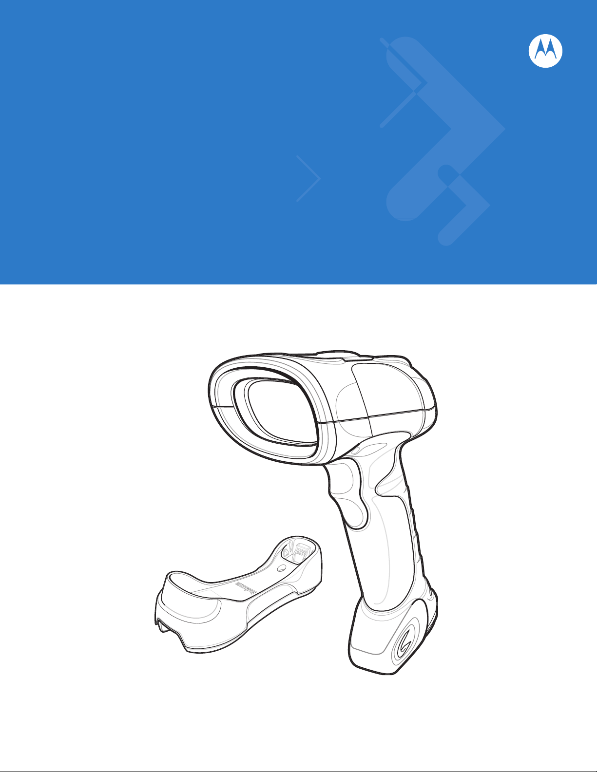
The Symbol LS3578 scanner combines excellent scanning performance and advanced ergonomics to provide the
best value in a lightweight laser scanner, ensuring comfort and ease of use for extended periods of time.
Scan Window
Tether Plate
LED
Indicators
Scan Trigger
Figure 1-1
Symbol LS3578 Scanner
Page 20

1 - 2 Symbol LS3578 Product Reference Guide
This scanner supports the following host interfaces through communication with a cradle:
•
Standard RS-232 connection to a host.
•
Keyboard wedge connection to a host, where scanned data is interpreted as keystrokes. The following
international keyboards are supported (for Windows™ environment): North American, German, French,
French Canadian, Spanish, Italian, Swedish, UK English, Japanese, and Brazilian-Portuguese.
•
IBM® 468X/469X hosts.
•
USB connection to a host. The scanner autodetects a USB host and defaults to the HID keyboard interface
type. Select other USB interface types by scanning programming bar codes. The following international
keyboards are supported (for Windows™ environment): North America, German, French, French Canadian,
Spanish, Italian, Swedish, UK English, Japanese, and Brazilian-Portuguese.
•
Synapse capability, which allows connection to a wide variety of host systems using a Synapse cable and
Synapse adapter cable. The scanner autodetects the Synapse interface.
•
Configuration via 123Scan.
Unpacking the Scanner
Remove the scanner from its packing and inspect it for damage. If the scanner was damaged in transit, contact
Motorola Enterprise Mobility Support. See page xv for contact information. KEEP THE PACKING. It is the
approved shipping container and should be used if the equipment ever needs to be returned for servicing.
The Cradle
The cradles serve as a stand and charger for the Symbol LS3578 co rdless scanner. Some models also provide a
host communication interface. There are four versions of the cradle:
•
The STB3508 cordless cradle sits on a desktop or mounts on a wall, and charges the Symbol LS3578
cordless scanner. An external power supply or a powered host cable charges the scanner.
•
The STB3578 cordless cradle sits on a desktop or mounts on a wall, and charges the Symbol LS3578
cordless scanner This cradle also provides host communication by receiving scanner data via a Bluetooth
radio, and sending that data to the host through an attached cable. An external power supply or a powered
host cable charges the scanner.
•
The FLB3508 cordless cradle charges the Symbol LS3578 cordless scanner. The cradle attaches to a
mounting bracket using three isolators, and th e bracket then mount s on the forklift surface. A portable power
supply on the forklift provides power to the cradle.
•
The FLB3578 cordless cradle charges the Symbol LS3578 cordless scanner, and provides host
communication by receiving scanner dat a via a Bluetoo th radio , and sending tha t dat a to the ho st through an
attached cable. The crad le attaches to a mounting bra cket using three isolators, and the br acket then mounts
on the forklift surface. A portable power supply on the forklift provides power to the cradle.
DO NOT use these cradles with a Symbol LS3478 scanner. Likewise, DO NOT use cradles designed for the
LS3478 to charge or provide communication for a Symbol LS3578 scanner.
NOTE For more information about communication between the scanner, cradle, and host, see Chapter 4, Radio
Communications.
For more information about mounting options and procedures, refer to the documentation included with the cradle.
Page 21
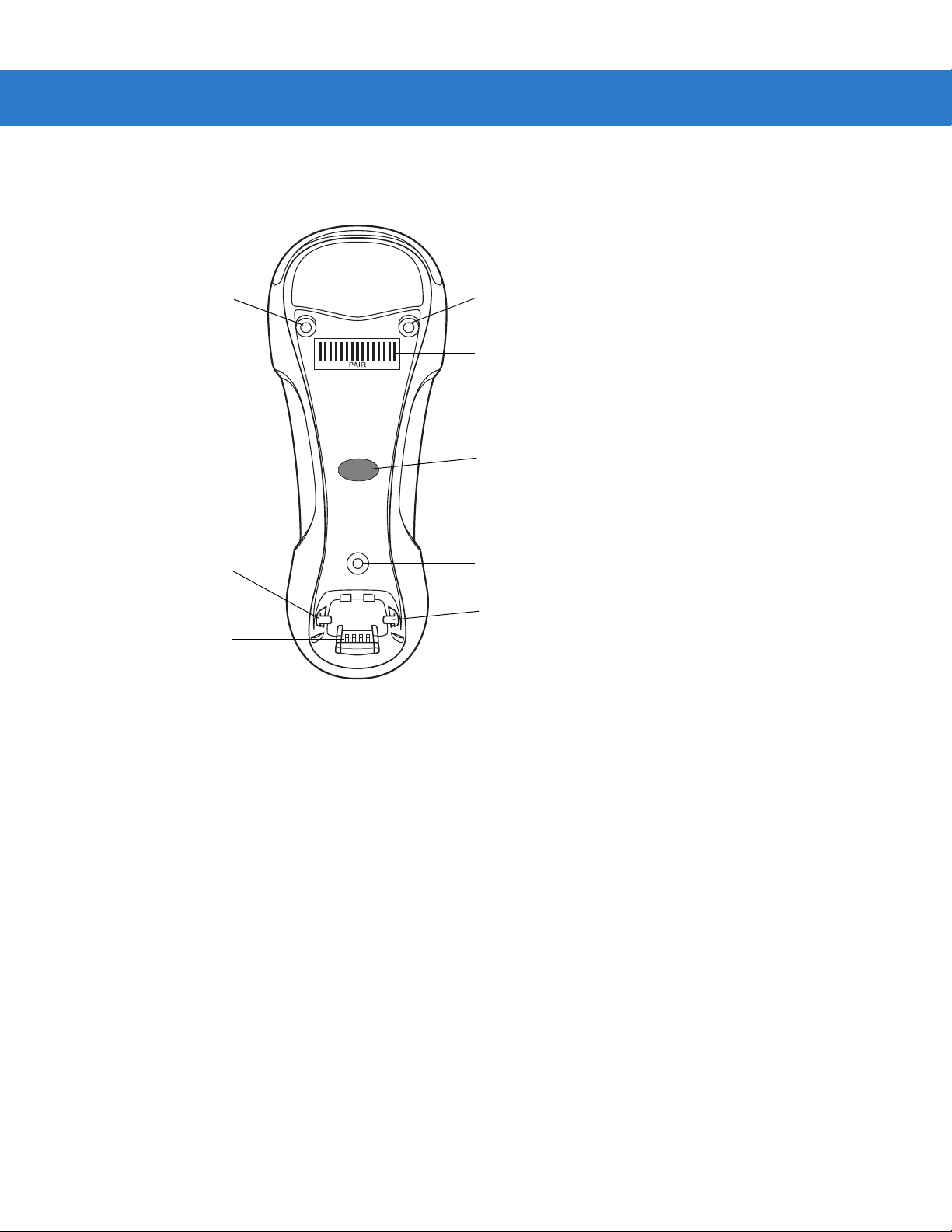
Cradle Parts
Getting Started 1 - 3
Mounting
Screw Hole
Charging/
Communications
Contacts
Figure 1-2
Cradle Front View
Latch
Mounting
Screw Hole
Pairing
Bar Code
LED
Mounting
Screw Hole
Latch
Page 22
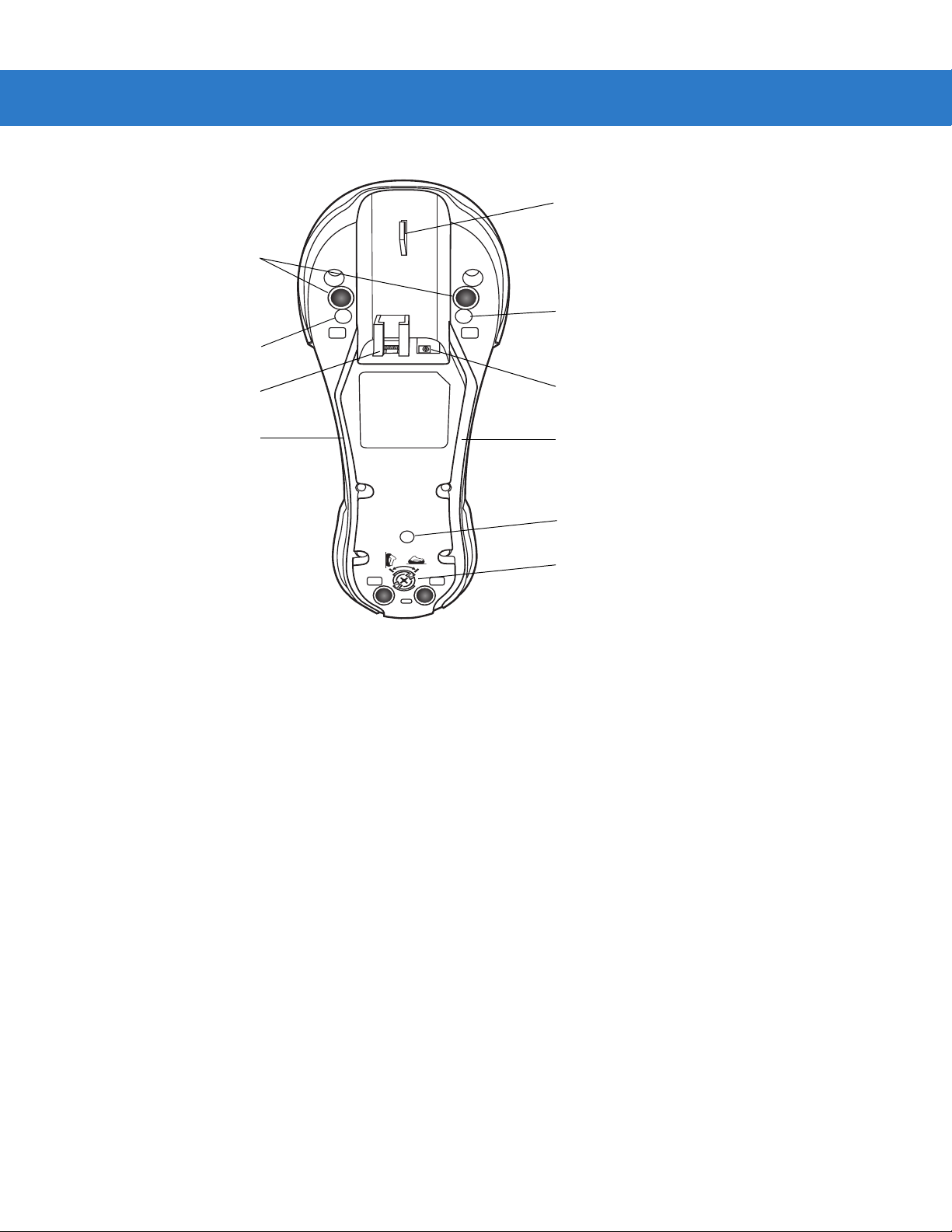
1 - 4 Symbol LS3578 Product Reference Guide
Rubber Feet
(STB3508/3578 Only)
Mounting Screw Hole
Cable Hook
Mounting Screw Hole
Host Port
Power Cable Groove
Figure 1-3
Cradle Back View
Power Port
Host Cable Groove
Mounting Screw Hole
Converter Knob
Connecting the Cradle
Important: Connect the interface cable and power supply (if necessary) in the following order to ensure proper operation of the
scanner and cradle.
Connecting STB3508/3578 Cradle
1. Insert the interface cable into the cradle's host port. See Figure 1-4.
2. Connect the other end of the interface cable to the host.
3. If necessary, connect the power supply to the cradle's power port (if the interface requires, or to allow fast
charging of the scanner).
4. Connect the appropriate cable to the power supply and an AC power source, if necessary.
5. If applicable, thread the interface cable over the cable support hook and run the host and power cables into
their respective cable grooves.
6. Pair the scanner to the cradle by scanning the pairing bar code on the cradle.
7. If necessary, scan the appropriate host bar code (for non-autodetected interface s). See the specific host
chapter.
Page 23
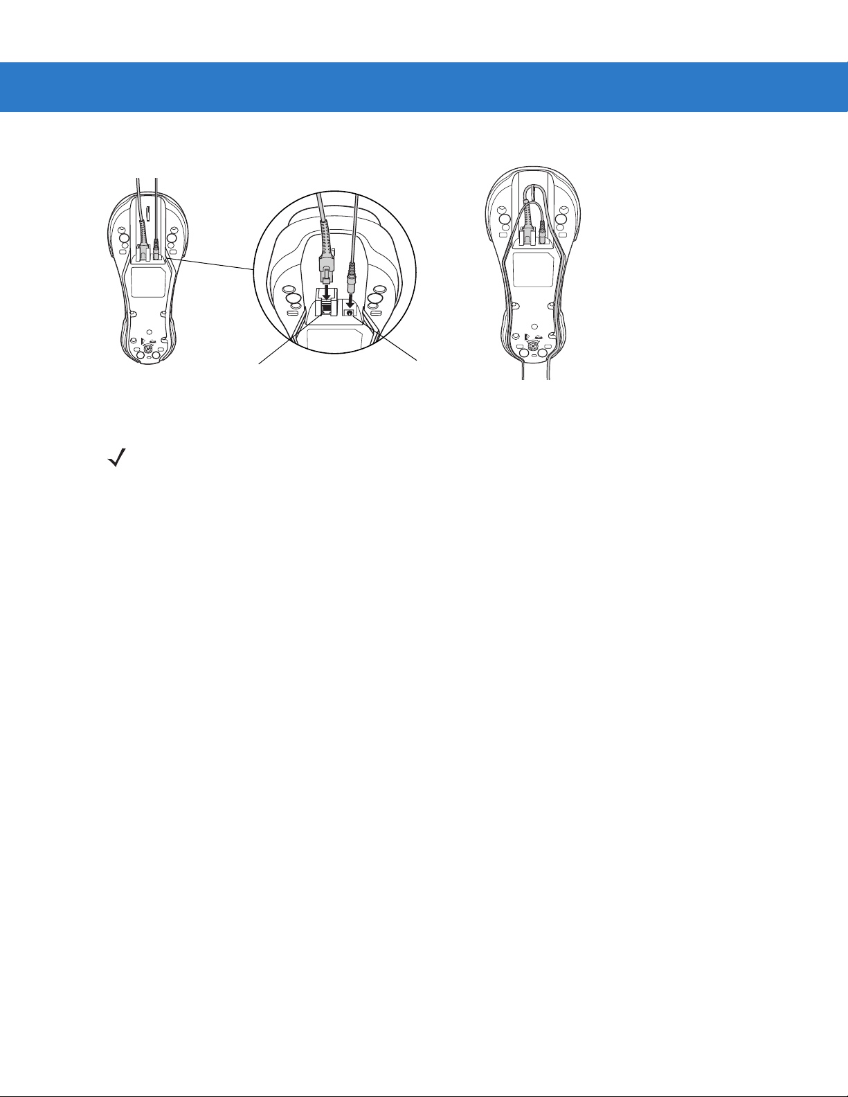
Getting Started 1 - 5
Power Port
Figure 1-4
NOTE Disconnect the power supply before changing host cables, or the scanner may not recognize the new
Host Port
Connecting the Cables to the Cradle
host.
Different cables are required for different hosts. The connectors illustrated in each host chapter are
examples only. The connectors may be different from those illustrated, but the steps to connect the
scanner remain the same
Connecting FLB3508/3578 Cradle
1. Insert the interface cable from the host computer into the cradle's host port. See Figure 1-4.
2. Connect the forklift power supply to the cradle's power port, if applicable.
3. Optionally, thread the host cable over the cable hook and run the host and power cables into their respective
cable grooves, or use cable ties to secure them to the mounting plate after attaching it to the cradle . For more
information about mounting options and procedures, refer to the documentation included with the cradle.
4. Pair the scanner with the cradle by scanning the pairing bar code on the cradle.
5. If necessary, scan the appropriate host bar code (for non-autodetected interface s). See the specific host
chapter.
Changing the Host Interface
To connect to a different host, or to the same host using a different cable:
1. Disconnect the power supply from the cradle, if used.
2. Disconnect the interface cable from the host.
3. Connect the interface cable to the new host, or the new interface cable to the existing host.
4. Reconnect the power supply, if required.
5. If necessary, scan the appropriate host bar code (for non-autodetected interface s). See the specific host
chapter.
Page 24
1 - 6 Symbol LS3578 Product Reference Guide
CAUTION If the scanner does not recognize the host, disconnect the power supply, then reconnect after
connecting the host cable.
Supplying Power to the Cradle
The cradle receives power from one of two sources:
•
An external power supply.
•
When connected to the host through an interface cable that supplies power.
The cradle detects whether the host or the external supply is supplying power . It always draws power from the
external supply when available, regardless of the presence of power from a host.
Using the USB Interface to Supply Power
When the cradle is connected to the host via the USB interface, the USB port can power the cradle so that an
external power supply is not necessary. Note that powering from a USB host charges the scanner at a slower rate
than when charging from an external power supply.
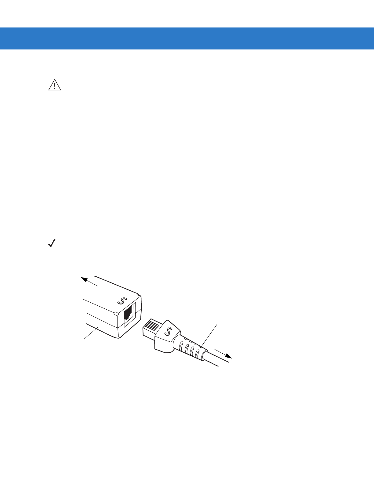
Connecting a Synapse Cable Interface
NOTE Refer to the Synapse Interface Guide provided with the Synapse cable for more information.
Symbol’s Synapse Smart Cables enable interfacin g to a variety of hosts. The appropriate Synapse cable detects
the host.
To host
Synapse adapter cable
Synapse Smart Cable
To cradle
Figure 1-5
1. Insert the Synapse adapter cable into the bottom of the cradle, as described in Connecting the Cables to the
Cradle on page 1-5.
Synapse Cable Connection
2. Align the ‘S’ on the Synapse adapter cable with the ‘S’ on the Synapse Smart Cable and plug the cable in.
3. Connect the other end of the Synapse Smart Cable to the host.
Mounting the Cradle
For information on mounting the cradle, refer to the documentation included with the cradle.
Page 25
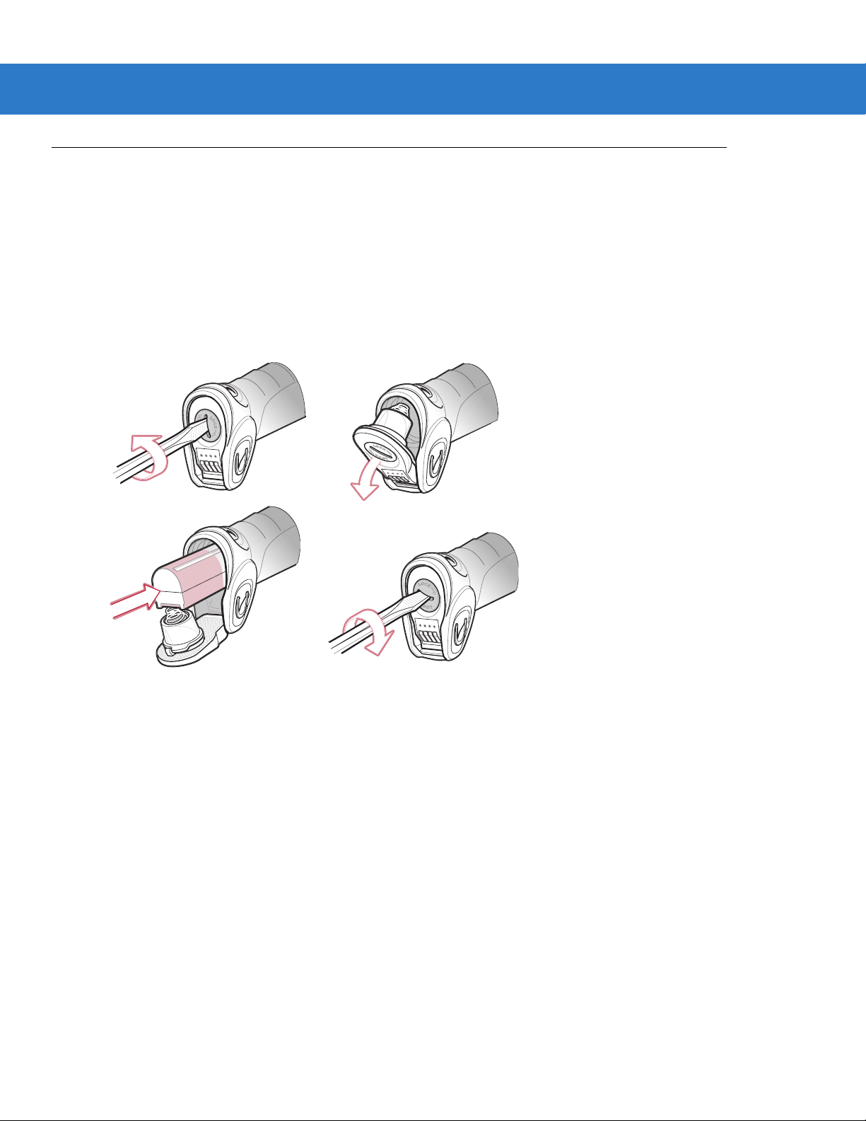
Inserting the Battery
The battery resides in a chamber in the scanner handle. To insert the battery:
1. Insert a coin or flathead screwdriver in the slot at the base of the scanner, then turn the slot counterclockwise
to release the latch.
2. Lift the latch.
3. If a battery is already installed, turn the scanner upright to slide the battery out.
4. Slide the new battery into the chamber, with the rounded side toward the back and the cont acts facing into the
chamber.
Getting Started 1 - 7
Figure 1-6
5. Close the latch.
6. Insert a coin or flathead screwdriver in the slot at the base of the scanner, press down gently, and turn the slot
clockwise to lock the latch in place.
Inserting the Battery
Page 26

1 - 8 Symbol LS3578 Product Reference Guide
Removing the Battery
To remove the battery:
1. Insert a coin or flathead screwdriver in the slot at the base of the scanner, then turn the slot counterclockwise
to release the latch.
2. Lift the latch.
3. Turn the scanner upright to slide the battery out.
Charging the Scanner Battery in the Cradle
For best performance, fully charge the scanner battery before using the scanner for the first time. To charge the
scanner battery , place the scanner in the cradle (see In serting the Scanner in the Cradle on p a ge 1-9) . The battery
begins charging when the scanner LED indicator starts flashing green. A complete charge of a fully discharged
battery can take up to four hours using external power and up to 10 hours using the interface cable.
Charge within the recommended temperature of 32° to 104° F (0° to 40° C) nominal, 41° to 95° F (5° to 35° C)
ideal.
For information on maximizing battery life, see Battery Maintenance on page 3-1.
Scanner Charging LED
The scanner’s green LED indicates charging activity (see Table 2-2 on page 2-4). If the scanner is charging in fast
mode (non-bus powered mode), the green LED blinks at a fast rate. If the scanner is charging in slow mode
(bus-powered mode), the LED blinks at a slow rate.
If the scanner’s red LED begins flashing, indicating a charging problem, remove the scanner from the cradle and
replace the battery. If the red LED continues flashing, contact Motorola Enterprise Mobility Support.
Page 27
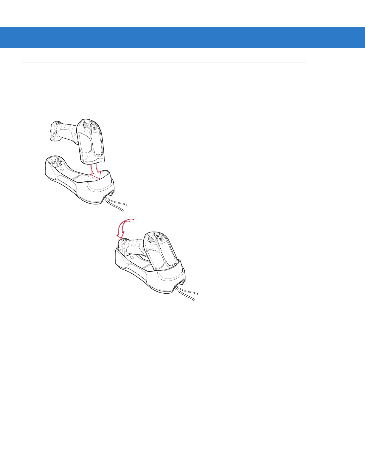
Inserting the Scanner in the Cradle
To insert the scanner in the cradle:
1. Insert the scanner into the cradle top first.
2. Push the handle until it clicks into place, engaging the contacts in the cradle and scanner.
Getting Started 1 - 9
Figure 1-7
Inserting the Scanner in the Cradle
Page 28

1 - 10 Symbol LS3578 Product Reference Guide
Sending Data to the Host Computer
The cradle receives data from the scanner via a wireless radio con nection and transmit s it to th e host computer via
the host cable. The scanner and cradle must be paired for successful wireless communication.
Pairing
Pairing registers a scanner to the cradle such that the scanner and cradle can exchange information. The
STB3578 and FLB3578 operate in two modes: Point-to-Point and Multipoint-to-Point. In Point-to-Point mode, pair
the scanner to the cradle either by inserting it in the cradle (if pairing on insertion is enabled), or by scanning the
pairing bar code. In Multipoint-to-Point mode, you can pair up to three scanners to one cradle. To use this feature,
scan the multipoint bar code in Multipoint-to-Point Communication on page 4-20.
The cradle includes pairing bar codes on both it s front and back. To pair the scanner with th e cradle, scan a pair ing
bar code. A high-low-high-low beep sequence followed by a low-high beep sequence indicates successful pairing
and connection to the remote device. A long low, long high beep sequence indicates unsuccessful pairing.
NOTE The pairing bar code that connects the scanner to a cradle is unique to each cradle.
Do not scan data or parameters until pairing completes.
Lost Connection to Host
If scanned data does not transmit to the cradle's host, ensure that all cables are firmly inserted and the power
supply is connected to an appropriate AC outlet, if applicable. If scanned data still does not transmit to the host,
reestablish a connection with the host:
1. Disconnect the power supply from the cradle.
2. Disconnect the host interface cable from the cradle.
3. Wait three seconds.
4. Reconnect the host interface cable to the cradle.
5. Reconnect the power supply to the cradle, if the host requires.
6. Reestablish pairing with the cradle by scanning the pairing bar code.
Configuring the Scanner
Use the bar codes in this manual or the 123Scan configuration program to configure the scanner. See Chap te r 5,
User Preferences and each host chapter for information about programming the scanner using bar code menus.
See Chapter 10, 123Scan to configure the scanner using this configuration program. 123Scan includes a help file.
Radio Communications
The scanner can communicate with remote devices via Bluetooth Technology Profile Support, or by pairing with a
cradle. For radio communication parameters, detailed information about operational modes, Bluetooth Technology
Profile Support and pairing, see Chapter 4, Radio Communications.
Page 29

Chapter 2 Scanning
Introduction
This chapter provides beeper and LED definitions, scanning techniques, general scanning instructions and tips,
and decode zone diagrams.
Beeper Definitions
The scanner emits different beeper sequences and patterns to indicate its status. Table 2-1 defines beep
sequences that occur during both normal scanning and while programming the scanner.
Table 2-1
Standard Use
Short low-short medium-short high beeps Power up.
One short high beep A bar code symbol was decoded (if decode beeper is enabled).
Four long low beeps A communication error occurred while transmitting a scanned
Low beep The scanner detects power when inserted into a cradle.
Low-high-low-high beeps Out of memory - the scanner cannot store the new bar code data.
Four short high beeps Low battery indication.
Five long low beeps Conversion or format error.
Wireless Operation
Short low-high beeps Scanner has paired with the cradle.
Standard Beeper Definitions
Beeper Sequence Indication
symbol to a host. The data is ignored. This occurs if the scanner is
not properly configured or if the scanner has disconnected from
the cradle.
Note: This feature can be disabled.
The scanner was inserted in an incompatible/older cradle.
Page 30

2 - 2 Symbol LS3578 Product Reference Guide
Table 2-1
Standard Beepe r Definitions (Continued)
Beeper Sequence Indication
Short high-low beeps Scanner has unpaired with the cradle.
Note: When connected to a remote device using SPP or HID, if a
disconnect beep sequence sounds immediately after scanning a
bar code, check the host device to determine if it received the
transmitted data. The scanner may have transmitted the last bar
code scanned after losing the connection.
Long low-long high beeps Unsuccessful pairing attempt. See
Long low-long high-long low-long high
beeps
page 4-15
Remote device rejected connection attempt, possibly due to an
attempt to pair with a cradle that is already paired with the
.
Auto-reconnect Feature on
maximum number of scanners.
Four long low beeps 1. A transmission error was detected in a scanned symbol. The
data is ignored. This occurs if a unit is not properly configured.
Check option setting.
2. When communicating with a cradle, the cradle acknowledges
receipt of data. If the acknowledgment is not received, this
transmission error beep sequence sounds. Data may still have
been received by the host. Check the host system for receipt of
transmitted data. If data was not received by the host, re-scan the
bar code.
Five high beeps Emitted every 5 seconds while a reconnection attempt is in
progress. See
Parameter Menu Scanning
Auto-reconnect Feature on page 4-15
.
Short high beep Correct entry scanned or correct menu sequence performed.
Long low-long high beeps Input error; incorrect bar code, programming sequence, or
Cancel
scanned. Scanner remains in program mode.
Short high-short low beeps Keyboard parameter selected. Enter value using numeric bar
codes.
Short high-short low-short high-short low
Successful program exit with change in the parameter setting.
beeps
Long low-long high-long low-long high
beeps
ADF Programming Normal Data Entry
Out of host parameter storage space. See
page 5-4
.
Default Parameters on
High-low beeps Enter another digit. Add leading zeros to the front if necessary.
Low-low beeps Enter another alphabetic character or scan the End of Message
bar code.
High-high beeps Enter another criterion or action, or scan the Save Rule bar code.
High-low-high-low beeps Rule saved. Rule entry mode exited.
High-low-low beeps All criteria or actions cleared for current rule, continue entering
rule.
Page 31

Scanning 2 - 3
Table 2-1
Standard Beepe r Definitions (Continued)
Beeper Sequence Indication
Low beep Delete last saved rule. The current rule is left intact.
Low-high-high beeps All rules have been deleted.
Short low-short high-short low-short high
beeps
ADF Programming Error Indications
Out of host ADF parameter storage space. See
Parameters on page 5-4
.
Default
Low-high-low-high beeps Out of rule memory. Erase some existing rules, then try to save
rule again. (It is not necessary to re-enter the current rule.)
A Symbol LS3578 scanner was inserted into an STB3478 cradle.
Low-high-low beeps ADF transmit error. Cancel rule entry. Rule entry mode exited
because of an error or the user asked to exit rule entry.
Low-high beeps Entry error, wrong bar code scanned. Re-enter criterion or action.
All previously entered criteria and actions are retained. Criteria or
action list is too long for a rule.
Host Specific
USB Only
Four high beeps The scanner did not complete initialization. Wait several seconds
and scan again.
Short low-short medium-short high
beeps (power-up sequence)
The scanner scanned a USB device type. The scanner must
establish communication with the bus before it can operate at the
highest power level.
Short low-short medium-short high
beeps (power-up sequence) occur
more than once
RS-232 only
The USB bus may cause power to the scanner to cycle on and off
more than once. This is normal and usually happens when the
host PC cold boots.
High-high-high-low beeps RS-232 receive error.
High beep A <BEL> character is received and Beep on <BEL> is enabled
(Point-to-Point mode only).
Page 32

2 - 4 Symbol LS3578 Product Reference Guide
LED Definitions
In addition to beeper sequences, the scanner uses a two-color LED to indicate its status, and the cradle’s LED
indicates charge and communication status. Table 2-2 explains scanner LED sequences, and Table 2-3 explains
cradle LED sequences.
Table 2-2
Standard Use
Off No power is applied to the scanner (battery is discharged or removed);
Green A bar code was successfully decoded.
Red A data transmission error, scanner malfunction, or the Symbol LS3578
Charging Use
Green Slow Flash The scanner charges at the slow rate (used when a host cable powers the
Green Fast Flash The scanner charges at the fast rate (used when an external power supply
Red flash Charging problem. Contact
Red and green flash Temperature fault. Move the cradle to a location where the temperature is
Scanner LED Status Indications
LED Indication
scanner is in low power and ready to scan.
scanner was inserted into an STB3478 cradle.
cradle).
powers the cradle).
Motorola Enterprise Mobility Support
The Symbol LS3578 scanner was inserted into an STB3478 cradle.
o
- 40o C; optimal charging temperature is 5o - 35o C.
0
.
Table 2-3
Flashing Green The cradle is externally powered with a USB host interface that has
Flashing Red Transmission error, or you inserted an LS3478 scanner into the STB3578
Cradle LED Status Indications
LED Indication
suspended the cradle. The cradle is no longer connected to the scanner bu t
the can charge the scanner. Scan the pairing bar code to re-pair the
scanner.
cradle.
Page 33

Scanning
See Chapter 1, Getting Started to install and program the scanner. To scan:
1. Aim the scanner at the bar code.
2. Press the scan trigger.
Scanning 2 - 5
Figure 2-1
3. Ensure the scan line crosses every bar and space of the symbol.
4. The scanner beeps and the LED turns green to indicate a successful decode. See Table 2-1 and Table 2-2 for
beeper and LED definitions.
Aiming the Scanner
RIGHT
012345
WRONG
012345
Page 34

2 - 6 Symbol LS3578 Product Reference Guide
Aiming
Do not hold the scanner directly over the bar code. Laser light reflecting directly back into the scanner from the bar
code is known as specular reflection which can make de cod in g difficult.
Tilt the scanner up to 65° forward or back to achieve a successful decode. Simple practice shows what tolerances
to work within.
65°
Figure 2-2
65°
Optimum Scan Angles
Page 35

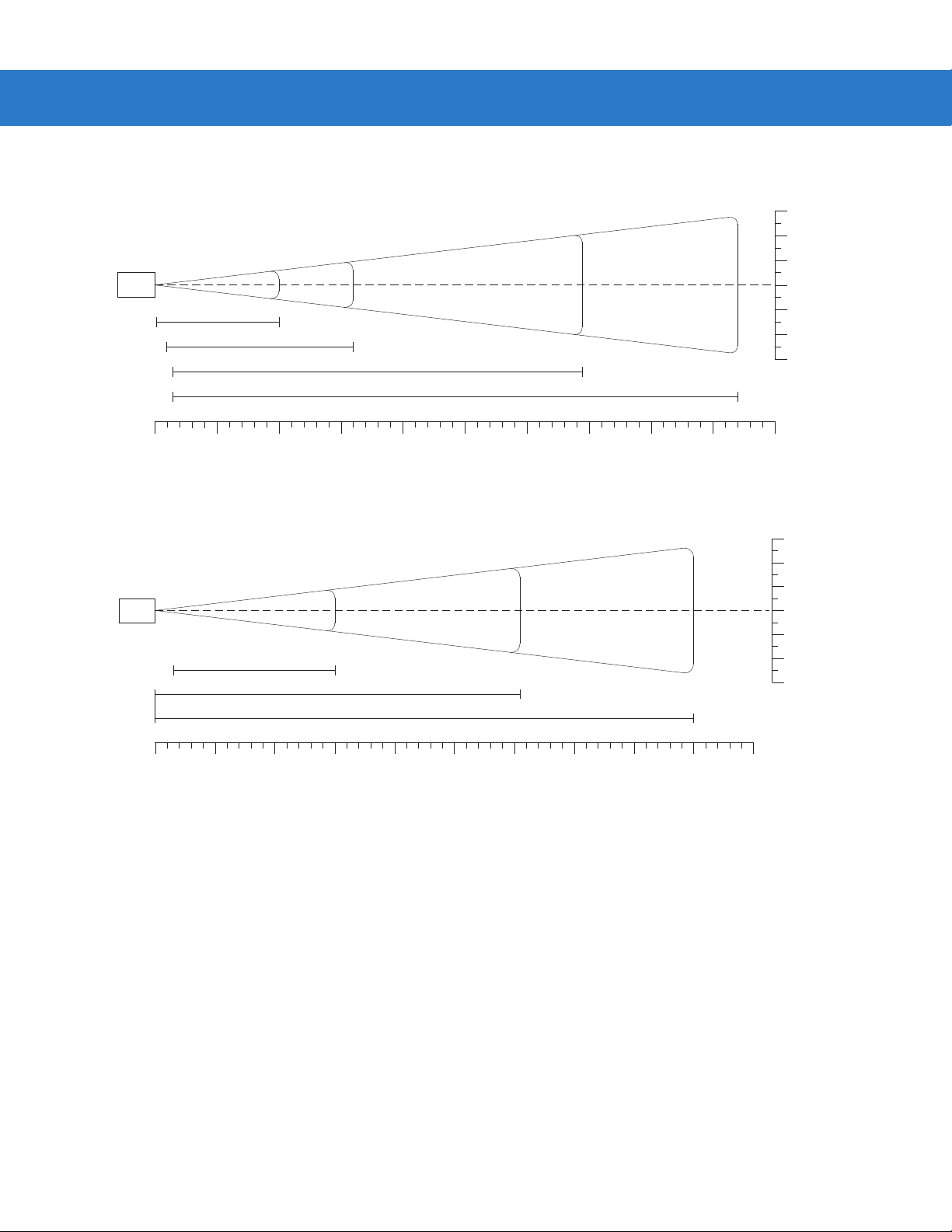
Decode Zone
Scanning 2 - 7
in. cm
30
76.2
20
50.8
Note: Typical performance at 68°F (20°C)
on high quality Code 39 and UPC symbols.
LS3578
FZ
5 mil
7.5 mil
13 mil
100% UPC
40 mil
55 mil
4.0"*
7.25"
39.5"
26.5"
67.0"
Depth of Field
2.5"
2.0" 15.75"
1.0" 24"
20 mil (80%MRD)
0"*
20 mil (31%MRD)
2.0"*
in.
0 1020304050607080
0 25.4 50.8 76.2 101.6 127.0 152.4 177.8 203.2
cm
*Minimum distance determined by symbol length and scan angle
84.0"
90
228.6
10
25.4
00
10
25.4
20
50.8
30
76.2
W
i
d
t
h
o
f
F
i
e
l
d
Figure 2-3
Symbol LS3578-FZ Decode Zone
Page 36
2 - 8 Symbol LS3578 Product Reference Guide
Note: Typical performance at 73.4°F (23°C)
on high quality Code 39 symbols.
LS3578
ER
0.25" 20"
2" 32"
in.
0 1020304050607080 90 100
cm
0 25.4 50.8 76.2 101.6 127.0 152.4 177.8 203.2 228.6 254.0
Note: Typical performance at 73.4°F (23°C)
on high quality Code 39 symbols.
LS3578
ER
*
7.5 mil
10 mil
15 mil
3" 69"
20 mil
3" 94"
15" 180"
55 mil
70 mil reflective
100 mil reflective
Depth of Field
365"
540"
in. cm
12
8
4
0
4
8
12
in. cm
72
182.9
48
121.9
24
61.0
0
0
24
61.0
48
121.9
72
182.9
30.5
20.3
10.2
0
10.2
20.3
30.5
W
i
d
t
h
o
f
F
i
e
l
d
W
i
d
t
h
o
f
F
i
e
l
d
in.
0 60 120 180 240 300 360 420 480 540 600
0 152.4 304.8 457.2 609.6 762.0 914.4 1066.8 1219.2 1371.6 1524.0
cm
Depth of Field
*Near range determined by degree of reflectivity and width of bar code.
Figure 2-4
Symbol LS3578-ER Decode Zone
Page 37

Chapter 3 Maintenance and Technical
Specifications
Introduction
This chapter provides suggested scanner maintenance, troubleshooting, technical specifications, and signal
descriptions (pinouts).
Maintenance
Cleaning the scan window is the only maintenance required. A dirty window can affect scanning accuracy.
•
Do not allow any abrasive material to touch the window.
•
Remove any dirt particles with a damp cloth.
•
Wipe the window using a tissue moistened with ammonia/water.
•
Do not spray water or other cleaning liquids directly onto the window.
Battery Maintenance
When batteries are stored over a year, battery cell manufacturers advise that some irreversible deterioration in
overall battery quality may occur. To minimize this los s, the y re co mm e nd sto ring ba tte r i es ha lf ch arge d in a dr y,
cool place between 41° and 77°F (5° and 25°C), the coo ler the better, and removed from the equipment to prevent
the loss of capacity . Batteries should be charged to half capacity at least once a year. In order to charge a battery
to half capacity , t ake a fully discharged battery and cha rge it for 2 hours. If an electrolyte leakage is observed, avoid
any contact with the affected area and properly dispose of the battery.
Page 38

3 - 2 Symbol LS3578 Product Reference Guide
Troubleshooting
Table 3-1
Scanner emits short low-short
medium-short high beep
sequence.
Nothing happens when scan
trigger is pressed.
Laser comes on, but scanner
does not decode the bar code.
Troubleshooting
Problem Possible Causes Possible Solutions
Scanner is powering up. Normal when scanner battery is inserted.
No power to the scanner. Check battery.
Ensure that end cap to battery chamber is
secured.
Scanner is disabled. For Simple Serial Interface (SSI), Synapse, or
IBM-468x mode, enable the scanner via the host
Motorola Enterprise
page xv
) for contact
If using RS-232 Nixdorf B
mode, CTS is not asserted.
Scanner is not programmed
for the correct bar code
type.
Bar code symbol is
unreadable.
interface. Otherwise, call
Mobility Support
information).
Assert CTS line.
Ensure the scanner is programmed to read the
type of bar code being scanned.
Check the symbol to ensure it is not defaced. Try
scanning test bar codes of the same bar code
type. See Appendix C, Sample Bar Codes for test
bar codes.
(see
Scanner emits four short high
beeps.
Scanner emits a disconnect
(short high-short low) beep
sequence.
Bar code is out of range of
the scanner.
Battery is low. Charge the battery. See
Scanner has disconnected
from cradle because it is too
far from the cradle.
Scanner has disconnected
from the cradle because the
cradle has lost power or
been placed in USB
suspend mode.
Move scanner closer to or further from bar code.
Battery in the Cradle on page 1-8
Move closer to the cradle and listen for a
reconnection beep (short low-short high).
Check power connections to cradle, and if using a
USB cable, check to make sure PC has not
entered a power save mode.
Charging the Scanner
.
Page 39

Maintenance and Technical Specifications 3 - 3
Table 3-1
Scanner emits four long low
beeps after scanning a bar
code.
Bar code is decoded, but data
is not transmitted to the host.
Troubleshooting (Continued)
Problem Possible Causes Possible Solutions
Incorrect host interface
cable is used.
Interface/power cables to
cradle are loose.
Scanner is not paired to a
cradle.
Scanner has disconnected. See disconnect beep sequence above.
A transmission error was
detected.
Cradle has not completed
USB initialization.
Scanner not paired to
host-connected cradle.
Cradle not programmed for
correct host interface.
Interface cable is loose. Ensure all cable connections are secure.
Ensure that correct host interface cable is used.
Ensure all cable connections are secure.
Scan the PAIR bar code on the cradle that is
connected to the host that is to receive data.
Ensure the cradle’s communication parameters
match the host's setting.
Wait several seconds and scan again.
Pair the scanner to the cradle (using PAIR bar
code on the cradle).
Check scanner host parameters or edit options.
Five long low beeps sound
after a bar code is decoded
Scanned data is incorrectly
displayed on the host.
Scanner emits short high-short
high-short high-long low beep
sequence when it is not in use.
Scanner emits long low-long
high beep sequence during
programming.
Cradle has lost connection
to host.
A conversion error or format
error has been detected.
Cradle host communication
parameters do not match
host’s parameters.
RS-232 receive error. Normal during host reset. Otherwise, ensure the
Input error or
code was scanned.
Cancel
bar
In this exact order: disconnect power supply;
disconnect host cable; wait three seconds;
reconnect host cable; reconnect power supply;
reestablish pairing.
Ensure the scanner’s conversion parameters are
properly configured.
Ensure proper host is selected.
For RS-232, ensure the cradle’s communication
parameters match the host’s settings.
For a Keyboard Wedge configuration, ensure the
system is programmed for the correct keyboard
type, and the CAPS LOCK key is off.
Ensure editing options (e.g., UPC-E to UPC-A
conversion) are properly programmed.
scanner’s RS-232 parity setting matches the host
setting.
Ensure the correct numeric bar codes, that are
within range for the parameter being pr ogrammed,
are being scanned.
Page 40

3 - 4 Symbol LS3578 Product Reference Guide
Table 3-1
Troubleshooting (Continued)
Problem Possible Causes Possible Solutions
Scanner emits short low-short
high- short low-short high beep
sequence while it is being
programmed.
Scanner emits one short high
beep when it is not in use.
Cradle does not work after
following installation
procedures.
Out of ADF parameter
storage space.
Out of Synapse parameter
storage space.
In RS-232 mode, a <BEL>
character is received and
Beep on <BEL> option is
enabled.
Cradle is not receiving
power.
Cable connections are not
secure.
The scanner is not inserted
properly in the cradle.
Cradle is not properly
connected to the host.
Erase all rules and re-program with shorter rules.
Scan
Set Synapse Defaults
code, from the
appropriate Synapse Interface Guide, for cables
no longer in use and re-program the scanner for
the current host interface.
Normal when Beep on <BEL> is enabled and the
scanner is in RS-232 mode.
Check system power.
Reinsert cables properly.
Reinsert scanner.
Check that host settings are correct, and connect
the cradle to the appropriate port on the host.
Battery does not charge. Cradle is outside the
charging temperature range.
NOTE If problems still occur, contact the distributor or Motorola Enterprise Mobility Support. See page xv for
contact information.
Charge within the recommended temperature of
32° to 104° F (0° to 40° C) nominal, 41° to 95° F
(5° to 35° C) ideal.
Page 41

Technical Specifications
Maintenance and Technical Specifications 3 - 5
Table 3-2
Battery Rechargeable Lithium-Ion 2200 mAh (3.7V)
Decode Capability UPC/EAN, Bookland EAN, UPC/EAN with supplementals, Code 128, UCC/EAN 128, ISBT
Beeper Operation User-selectable: Enable, Disable
Beeper Volume User-selectable: Three levels
Beeper Tone User-selectable: Three tones
Scan Repetition Rate 36 scans/second
Yaw Tolerance ± 50° from nominal ± 60° from nominal
Pitch Tolerance ± 65° from nominal ± 65° from nominal
Roll Tolerance ± 20° from nominal ± 10° from nominal
Print Contrast Minimum 25% minimum reflectance differential, measured at 650 nm.
Ambient Light Immunity
Indoor:
Outdoor:
Technical Specifications - Scanner
Item
Symbol LS3578-FZ Symbol LS3578-ER
128, Code 39, Trioptic Code 39, Code 93, Code 11, Interleaved 2 of 5, Discrete 2 of 5,
Codabar (NW-7), MSI, GS1 DataBar.
450 Ft Candles (4,842 Lux)
8,000 Ft Candles (86,080 Lux)
Description
450 Ft Candles (4,842 Lux)
4,000 Ft Candles (43,040 Lux)
Durability 6.5 ft (2.0 m) drops to concrete;
5 ft (1.5 m) at -4° F (-20° C)
Operating Temperature -4° to 122° F (-20° to 50° C)
Storage Temperature -40° to 158° F (-40° to 70° C)
Charging Temperature 32° to 104° F (0° to 40° C) nominal, 41° to 95° F (5° to 35° C) ideal
Humidity 5% to 95% (non-condensing)
ESD 15 kV air discharge
8 kV contact discharge
Weight 14.6 oz (414 grams) 14.8 oz (420 grams)
Dimensions:
Height
Width
Depth
Laser 650nm laser diode
Laser Classifications IEC 825-1 Class 2
Minimum Element Width 5 mil (0.127 mm) 7.5 mil (0.191 mm)
7.34 in. (18.65 cm)
4.82 in. (12.25 cm)
2.93 in. (7.43 cm)
Page 42

3 - 6 Symbol LS3578 Product Reference Guide
Table 3-2
Interfaces Supported Keyboard Wedge, RS-232, USB, IBM 468X/469X, Synapse, 123Scan
Radio Bluetooth, Class 2, Version 1.2, Serial Port & HID Profiles
Electrical Safety Certified Pending to UL1950, CSA C22.2 No.950. EN60950/IC950
Input Transient
Protection
EMI FCC Part 15 Class B, ICES-003 Class B European Union EMC Directive, Australian SMA,
Table 3-3
Technical Specifications - Scanner (Continued)
Description
Item
Symbol LS3578-FZ Symbol LS3578-ER
2.402 to 2.480 GHz Adaptive Frequency Hopping
(co-existence with 802.11 wireless networks)
Data rate: 720 kbps
IEC 1000-4-(2,3,4,5,6,11)
Taiwan EMC, Japan VCCI/MITI/Dentori
Technical Specifications - Cradles
Description
Item
STB3508 and FLB3508 STB3578 and FLB3578
Power Requirements 4.75 - 14.0 VDC
Typical Current Draw
Not Charging: 35 mA @ 5V
45 mA @ 9V
Fast Rate Charge: 850 mA @ 5V
610 mA @ 9V
Slow Rate Charge: 400 mA @ 5V
275 mA @ 9V
Interfaces Supported None Keyboard Wedge, RS-232, USB, IBM
Operating Temperature -4° to 122° F (-20° to 50° C)
Storage Temperature -40° to 158° F (-40° to 70° C)
Charging Temperature 32° to 104° F (0° to 40° C) nominal, 41° to 95° F (5° to 35° C) ideal
Humidity 5% to 95% (non-condensing)
ESD 15 kV air discharge
8 kV contact discharge
Weight 10.5 oz (298 grams)
80 mA @ 5V
85 mA @ 9V
920 mA @ 5V
655 mA @ 9V
440 mA @ 5V
310 mA @ 9V
468X/469X, Synapse
Page 43
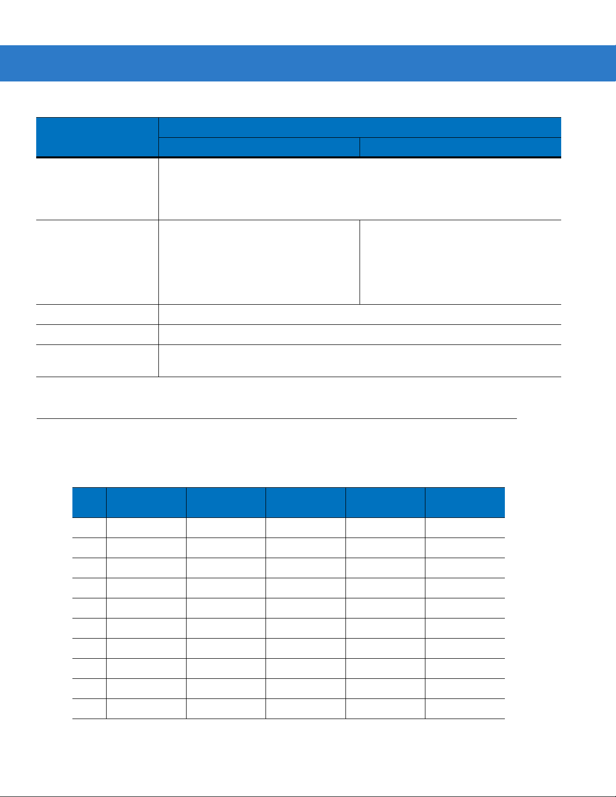
Maintenance and Technical Specifications 3 - 7
Table 3-3
Dimensions:
Radio N/A Bluetooth, Class 2, Version 1.2, Serial Port
Electrical Safety Certified Pending to UL1950, CSA C22.2 No.950. EN60950/IC950
Input Transient Protection IEC 1000-4-(2,3,4,5,6,11)
EMI FCC Part 15 Class B, ICES-003 Class B European Union EMC Directive, Australian SMA,
Technical Specifications - Cradles (Continued)
Item
STB3508 and FLB3508 STB3578 and FLB3578
Height
Width
Depth
9.5 in. (24.1 cm)
4.0 in (10.2 cm)
2.9 in (7.4 cm)
Taiwan EMC, Japan VCCI/MITI/Dentori
Description
& HID Profiles
2.402 to 2.480 GHz Adaptive Frequency
Hopping (co-existence with 802.11 wireless
networks)
Data rate: 720 kbps
Scanner Signal Descriptions
The signal descriptions in Table 3-4 apply to the 10-pin RJ connector on the cradle and are for reference only.
Table 3-4
Pin IBM Synapse RS-232
1 Reserved SynClock Reserved Reserved Jump to Pin 6
2 Power Power Power Power Power
3 Ground Ground Ground Ground Ground
4 IBM_A(+) Reserved TxD KeyClock Reserved
5 Reserved Reserved RxD TermData D +
6 IBM_B(-) SynData RTS KeyData Jump to Pin 1
7 Reserved Reserved CTS TermClock D 8 Reserved Reserved Reserved Reserved Reserved
9 Reserved Reserved Reserved Reserved Reserved
10 Reserved Reserved Reserved Reserved Reserved
Cradle to Host Pin-outs
Keyboard
Wedge
USB
Page 44
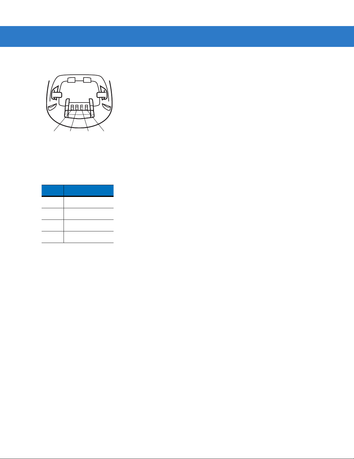
3 - 8 Symbol LS3578 Product Reference Guide
Figure 3-1 illustrates the positions of the cradle pins.
Pin 4 Pin 3 Pin 2
Figure 3-1
Cradle Pin Assignments
Pin 1
The signal descriptions in Table 3-5 apply to the connector from the scanner to the cradle and are for refere nc e
only .
Table 3-5
Scanner to Cradle Pin-outs
Pin Signal
1VCC
2CRADLE_TXD
3 CRADLE_RXD
4GND
Page 45

Chapter 4 Radio Communications
Introduction
This chapter provides information about the modes of op eration and fea tures available for wire less communication
between scanners, cradles and hosts. The chapter also includes the parameters necessary to configure the
scanner.
The scanner ships with the settings shown in the Table 4-1 on page 4-2 (also see Appendix A, Standard Default
Parameters for all host device and miscellaneous scanner defaults). If the default values suit requirements,
programming is not necessary.
To set feature values, scan a single bar code or a short bar code sequence. The settings are stored in non-volatile
memory and are preserved even when th e sca nn e r is powered down.
If not using a Synapse or USB cable with the cradle, select a host type (see each host chapter for specific host
information) after the power-up beeps sound. This is only necessary upon the first power-up when connected to a
new host.
To return all features to default values, scan a bar code in Default Parameters on page 5-4. Throughout the
programming bar code menus, default values are indicated with asterisks (
*).
*Disable Pair on Contacts
Feature/Option* Indicates Default
Scanning Sequence Examples
In most cases, scan one bar code to set a specific parameter value.
Errors While Scanning
Unless otherwise specified, to correct an error during a scanning sequence, just re-scan the correct parameter.
Page 46

4 - 2 Symbol LS3578 Product Reference Guide
Radio Communications Parameter Defaults
Table 4-1 lists the defaults for radio communication parameters. If you wish to change any option, scan the
appropriate bar code(s) provided in this chapter.
NOTE See Appendix A, Standard Default Parameters for all user preferences, hosts, symbologies, and
miscellaneous default parameters.
Table 4-1
Bluetooth Host (Host Type) Cradle Host 4-5
Bluetooth Friendly Name Scanner name and
Discoverable Mode General 4-7
Country Keyboard Types (Country Code) North American 4-9
HID Keyboard Keystroke Delay No Delay (0 msec) 4-11
CAPS Lock Override Disable 4-11
Ignore Unknown Characters Enable 4-12
Emulate Keypad Disable 4-12
Keyboard FN1 Substitution Disable 4-13
Function Key Mapping Disable 4-13
Simulated Caps Lock Disable 4-14
Convert Case No Case Conversion 4-14
Radio Communication Default Table
Parameter Default
4-7
serial number
Page
Number
Beep on Reconnect Attempt Disable 4-15
Reconnect Attempt Interval 30 sec 4-16
Auto-reconnect in Bluetooth Keyboard
Emulation (HID Slave) Mode
Modes of Operation
(Point-to-Point/Multipoint-to-Point)
Parameter Broadcast (Cradle Host Only) Enable 4-21
Pairing Modes Unlocked 4-22
Pairing on Contacts Disable 4-23
Connection Maintenance Interval 15 min 4-24
On Bar Code Data 4-18
Point-to-Point 4-20
Page 47

Radio Communications 4 - 3
Table 4-1
Authentication Disable 4-27
Variable Pin Code Static 4-28
Encryption Disable 4-29
Radio Communication Default Table (Continued)
Parameter Default
Wireless Beeper Definitions
When the scanner scans the pairing bar code it issues various beep sequences indicating successful or
unsuccessful operations. See Tab l e 4- 2 for beep sequences that occur during pairing operations.
Table 4-2
Short low-high beeps Scanner has paired with the cradle.
Short high-low beeps Scanner has unpaired with the cradle.
Wireless Beeper Definitions
Beeper Sequence Indication
Page
Number
Note: When connected to a remote device using SPP or HID, if a
disconnect beep sequence sounds immediately after scanning a
bar code, check the host device to determine if it received the
transmitted data. The scanner may have transmitted the last bar
code scanned after losing the connection.
Long low-long high beeps Unsuccessful pairing attempt. See
page 4-15
Long low-long high-long low-long high
beeps
Four long low beeps 1. A transmission error was detected in a scanned symbol. The
Five high beeps Emitted every 5 seconds while a reconnection attempt is in
Remote device rejected connection attempt, possibly due to an
attempt to pair with a cradle that is already paired with the
maximum number of scanners.
data is ignored. This occurs if a unit is not properly configured.
Check option setting.
2. When communicating with a cradle, the cradle acknowledges
receipt of data. If the acknowledgment is not received, this
transmission error beep sequence sounds. Data may still have
been received by the host. Check the host system for receipt of
transmitted data. If data was not received by the host, re-scan the
bar code.
progress. See
.
Auto-reconnect Feature on page 4-15
Auto-reconnect Feature on
.
Page 48

4 - 4 Symbol LS3578 Product Reference Guide
Radio Communications Host Types
To set up the scanner for communication with a cradle, or to use standard Bluetooth profiles, scan the appropriate
host type bar code below.
•
Cradle Host (default) - Select this host type for scanner(s) to cradle operation. The scanner must then be
paired to the cradle and the cradle communicates directly to the host via the host interface cable connection.
•
Serial Port Profile (Master) - Select this host type for Bluetooth Technology Profile Support (see page 4-6).
The scanner connects to the PC/host via Bluetooth and behaves like there’ s a serial connection. The scanne r
initiates the connection to the remote device and is the Master. Scan Serial Port Profile (Master), then scan
the PAIR bar code for the remote device. See Pairin g Bar C ode F or mat on page 4-24 for information about
creating a pairing bar code for a remote device.
•
Serial Port Profile (Slave) - Select this host type for Bluetooth Tech nology Profile Support (see page 4-6). The
scanner connects to the PC/host via Bluetooth and behaves like there’s a serial connection. The scanner
accepts incoming connection requested from a remote device and is the Slave. Scan Serial Port Profile
(Slave) and wait for the incoming connection.
•
Bluetooth Keyboard Emulation (HID Slave) - Select this host type for Bluetooth Technology Profile Support.
(See p age 4-6 for Bluetooth Technology Profile Support and Master/Slave definitions.) The scanner co nnects
to the PC/host via Bluetooth and behaves like a keyboard. The scanner accepts incoming connection
requested from a remote device and is the slave. Scan Bluetooth Keyboard Emulation (HID Slave) and
wait for the incoming connection.
NOTE 1.The scanner supports keyboard emulation over the Bluetooth HID profile. For detailed information, and
HID host parameters, see HID Host Parameters on page 4-8.
2. When the scanner is paired to the cradle in SPP Master or Cradle Host mode, the scanner
automatically tries to reconnect to a remote device when a disconnection occurs that is due to the radio
losing communication. For more information see Auto-reconnect Feature on page 4-15.
Page 49

Radio Communications Host Types (continued)
*Cradle Host
Serial Port Profile (Master)
Radio Communications 4 - 5
Serial Port Profile (Slave)
Bluetooth Keyboard Emulation (HID Slave)
Page 50

4 - 6 Symbol LS3578 Product Reference Guide
Bluetooth Technology Profile Support
With Bluetooth Technology Profile Support, the cradle is not required for wireless communication. The scanner
communicates directly to the host using Bluetooth technology. The scanner support s the stan dard Blueto oth Serial
Port Profile (SPP) and HID Profiles which enable the scanner to communicate with other Bluetooth devices that
support these profiles.
•
SPP - the scanner connects to the PC/host via Bluetooth and performs like there’s a serial connection.
•
HID - the scanner connects to the PC/host via Bluetooth and performs like a keyboard.
Master/Slave Set Up
The scanner can be set up as a Master or Slave.
When the scanner is set up as a Slave, it is discoverable and connectable to other devices. When the scanner is
set up as a Master, the Bluetooth address of the remote device to which a connection is requested is required. A
pairing bar code with the remote device address must be created and scanned to attempt a connection to the
remote device. See the Pairing Bar Code Format on page 4-24 for information about creating a pairing bar code.
Master
When the scanner is set up as a Master (SPP), it initiates the radio connection to a slave device. Initiating the
connection is done by scanning a pairing bar code for the remote device (see Pairing Bar Code Format on page
4-24).
Slave
When the scanner is set up as a Slave device (SPP or HID), the scanner accepts an incoming connection request
from a remote device.
NOTE The number of scanners is dependent on the host’s capability.
Page 51

Radio Communications 4 - 7
Bluetooth Friendly Name
Y ou can set a meaningful na me for the scanner that appear s in the application during de vice discovery. The default
name is the scanner name followed by its serial number, e.g.,
reverts the scanner to this name; use custom defaults to maintain the user-programmed name through a Set
Defaults operation.
To set a new Bluetooth Friendly Name, scan the following bar code, then scan up to 23 characters from Appendix
E, Alphanumeric Bar Codes. If the name contains less tha n 23 characters, scan End of Messag e on page E-7 after
entering the name.
NOTE If your application allows you to set a device name, this takes precedence ov er the Bluetooth Friendly
Name.
LS3578 123456789ABCDEF. Scanning Set Defaults
Bluetooth Friendly Name
Discoverable Mode
Select a discoverable mode based on the device initiating discovery:
•
Select General Discoverable Mode when initiating connection from a PC.
•
Select Limited Discoverable Mode when initiating connection from a mobile device (e.g., Motorola Q), and
the device does not appear in General Discoverable Mode. Note that it can take lon ger to discover the device
in this mode.
The device remains in Limited Discoverable Mode for 30 seconds, and green LEDs flash while in this mode.
It is then non-discoverable. To re-active Limited Discoverable Mode, press the trigger.
*General Discoverable Mode
Limited Discoverable Mode
Page 52

4 - 8 Symbol LS3578 Product Reference Guide
HID Host Parameters
The scanner supports keyboard emulation over the Bluetooth HID profile. In this mode the scanner can interact
with Bluetooth enabled hosts supporting the HID profile as a Bluetooth keyboard. Scanned data is transmitted to
the host as keystrokes.
Following are the keyboard parameters supported by the HID host.
Page 53

HID Country Keyboard Types (Country Codes)
Scan the bar code corresponding to the keyboard type.
*North American Standard Keyboards
French Windows
Radio Communications 4 - 9
German Windows
French Canadian Windows 98
Spanish Windows
Italian Windows
Page 54

4 - 10 Symbol LS3578 Product Reference Guide
HID Country Keyboard Types (Country Codes - continued)
Swedish Windows
UK English Windows
Japanese Windows
French Canadian Windows 2000/XP
Portuguese/Brazilian Windows
Page 55

Radio Communications 4 - 11
HID Keyboard Keystroke Delay
This parameter sets the delay, in milliseconds, between emulated keystrokes. Scan a bar code below to increase
the delay when the HID host requires a slower trans mission of data.
*No Delay (0 msec)
Medium Delay (20 msec)
Long Delay (40 msec)
HID CAPS Lock Override
When enabled, the case of the data is preserved regardless of the state of the caps lock key. This setting is always
enabled for the “Japanese, Windows (ASCII)” keyboard type and can not be disabled.
*Do Not Override Caps Lock Key
(Disable)
Override Caps Lock Key
(Enable)
Page 56

4 - 12 Symbol LS3578 Product Reference Guide
HID Ignore Unknown Characters
Unknown characters are characters the host does not recognize. When Send Bar Codes With Unknown
Characters is scanned, all bar code dat a is sent except for un known ch arac ters, an d no err or be ep s sound . Wh en
Do Not Send Bar Codes With Unknown Characters is scanned, bar codes containi ng at least one unknown
character are not sent to the host, and an error beep sounds.
*Send Bar Codes With Unknown Characters
(Enable)
Do Not Send Bar Codes With Unknown Characters
(Disable)
Emulate Keypad
When enabled, all characters are sent as ASCII sequences over the numeric keypad. For example, ASCII A is sent
as "ALT make" 0 6 5 "ALT Break."
*Disable Keypad Emulation
Enable Keypad Emulation
Page 57

Radio Communications 4 - 13
HID Keyboard FN1 Substitution
When enabled, this parameter allows replacement of any FN1 character in an EAN128 bar code with a Key
Category and value chosen by the user. See FN1 Substitution Values on page 5-15 to set the Key Category and
Key Value.
*Disable Keyboard FN1 Substituti o n
Enable Keyboard FN1 Substitution
HID Function Key Mapping
ASCII values under 32 are normally sent as control-key sequences. When this parameter is enabled, the keys in
bold are sent in place of the standard key mapping (see Table 8-2 on page 8-13). Table entries that do not have a
bold entry remain the same whether or not this parameter is enabled.
*Disable Function Key Mapping
Enable Function Key Mapping
Page 58

4 - 14 Symbol LS3578 Product Reference Guide
Simulated Caps Lock
When enabled, the scanner inverts upper and lower case characters on the scanner bar code as if the Caps Lock
state is enabled on the keyboard. This inversion is don e re gar dle ss of the curre nt state of the keyboard Caps L ock
state.
*Disable Simulated Caps Lock
Enable Simulated Caps Lock
Convert Case
When enabled, the scanner converts all bar code dat a to the selected case.
*No Case Conversion
Convert All to Upper Case
Convert All to LowerCase
Page 59

Auto-reconnect Feature
When in SPP Master or Cradle Host mode, the scanner automatically tries to reconnect to a remote device when a
disconnection occurs that is due to the radio losing communication. This can happen if the scanner goes out of
range with the remote device, or if the remote device powers down. The scanner tries to reconnect for the pe riod of
time specified by the Reconnect Attempt Interval setting. During that time the green LED continues to blink.
If the auto-reconnect process fails due to page timeouts, the scanner sounds a page timeout beep (long low/long
high) and enters low power mode. The auto-reconnect process can be re-started by pulling the scanner trigger.
If the auto-reconnect process fails because the remote device rejects the connection attempt, the scanner sounds
a connection reject beep sequence (see Wireless Beeper Definitions on page 4-3) and deletes the remote pairing
address. If this happens, a pairing bar code must be scanned to attempt a new connection to the remote device.
NOTE If a bar code is scanned while the auto-reconnect sequence is in process, a transmission error beep
sequence sounds and the data is not transmitted to the host. After a connection is reestablished, normal
scanning operation returns. For error beep sequence definitions, see Beeper Definitions on page 2-1.
The scanner has memory available for storing a remote Bluetooth address for each Master mode (SPP, Cradle).
When switching between these modes, the scann e r auto matically tries to reconnect to the last device it was
connected to in that mode.
Radio Communications 4 - 15
NOTE Switching between Bluetooth host types by scanning a host type bar code (page 4-4) causes the radio to
be reset. Scanning is disabled during this time. It takes several seconds for the scanner to re-initialize the
radio at which time scanning is enabled.
Reconnect Attempt Beep Feedback
When a scanner disconnects as it goes out of range, it immediately attempts to reconnect. While the scanner
attempts to reconnect, the green LED continues to blink. If the auto-reconnect process fails, the scanner emits a
page timeout beep (long low/long high) and stops blinking the LED. The process can be restarted by pulling the
trigger.
The Beep on Reconnect Attempt feature is disabled by default. When enabled, the scanner emits 5 short high
beeps every 5 seconds while the reconnection attempt is in progress.
Scan a bar code below to enable or disable Beep on Reconnect Attempt.
*Disable Beep on Reconnect Attempt
Enable Beep on Reconnect Attempt
Page 60

4 - 16 Symbol LS3578 Product Reference Guide
Reconnect Attempt Interval
When a scanner disconnects as it goes out of range, it immediately attempts to reconnect for the default time
interval of 30 seconds. This time interval can be changed to one of the following options:
•
30 seconds
•
1 minute
•
5 minutes
•
30 minutes
•
1 hour
•
Indefinitely.
To set the Reconnect Attempt Interval, scan one of the bar codes below
*Attempt to Reconnect for 30 Seconds
Attempt to Reconnect for 1 Minute
Attempt to Reconnect for 5 Minutes
Attempt to Reconnect for 30 Minutes
Page 61

Reconnect Attempt Interval (continued)
Attempt to Reconnect for 1 Hour
Attempt to Reconnect Indefinitely
Radio Communications 4 - 17
Page 62

4 - 18 Symbol LS3578 Product Reference Guide
Auto-reconnect in Bluetooth Keyboard Emulation (HID Slave) Mode
In Bluetooth Keyboard Emulation (HID Slave) mode, select a re-connect option for when the scanner loses its
connection with a remote device:
•
Auto-reconnect on Bar Code Data: The scanner auto-reconnects when you scan a bar code. With this
option, a delay can occur when transmitting the first characters. The scanner sounds a decode beep upon
bar code scan, followed by a connection, a page timeout, a rejection beep, or a transmission error beep.
Select this option to optimize battery life on the scanner and mobile device. Note that auto-reconnect does
not occur on rejection and cable unplug commands.
•
Auto-reconnect Immediately: When the scanner loses connection, it attempts to reconnect. If a page
timeout occurs, the scanner attempts reconnect on a trigger pull. Select this optio n if the scanner’s battery life
is not an issue and you do not want a delay to occur when the first bar code is transmitted. Note that
auto-reconnect does not occur on rejection and cable unplug commands.
•
Disable Auto-reconnect in Bluetooth Keyboard Emulation (HID Slave) Mode: When the scanner loses
connection, you must re-establish it manually.
*Auto-reconnect on Bar Code Data
Auto-reconnect Immediately
Disable Auto-reconnect in
Bluetooth Keyboard Emulation (HID Slave) Mode
Page 63

Out of Range Indicator
An out of range indicator can be set by scanning Enable Beep on Reconnect Attempt on p age 4- 15 and extending
the time using the Reconnect Attempt Interval on page 4-16.
For example, with Beep on Reconnect Attempt disabled while the scanner loses radio connection when it is taken
out of range, the scanner attempts to reconnect silently during the time interval set by scanning a Reconnect
Attempt Interval.
When Beep on Reconnect Attempt is enabled, the scanner emits 5 high beeps every 5 seconds while the
reconnection attempt is in progress. If the Reconnect Attempt Interval is adjusted to a longer period of time, such
as 30 minutes, the scanner emits 5 high beeps e very 5 seconds for 30 minutes providing an out of range indicator.
Radio Communications 4 - 19
Page 64

4 - 20 Symbol LS3578 Product Reference Guide
Scanner(s) To Cradle Support
Modes of Operation
The charging cradle with radio supports two radio communication modes of operation, allowing the scanner to
communicate wirelessly:
•
Point-to-Point
•
Multipoint-to-Point.
Point-to-Point Communication
In Point-to-Point communication mode, the cradle allows one scanner to connect to it at a time. In this mode, the
scanner is paired to the cradle either by inser tion into the cradle (i f pairing on co ntact s is enabled, page 4-23), or by
scanning the PAIR bar code on the cradle. Communication can be locked, unlocked (default), or in a lock override
state (see Pairing Modes on page 4-22). In locked mode, locking intervals must be set by scanning a connection
maintenance interval bar code beginning on page 4-24.
To activate this mode of operation, scan Point-to-Point.
Multipoint-to-Point Communication
In Multipoint-to-Point communication mode, up to three scanners can be paired to one cra dle.
To activate this mode, the first scanner connected to the cradle must scan the Multipoint-to-Point bar code. This
mode allows a parameter broadcast (page 4-21) that clones all scanners paired to the cradle so only one scanner
needs to be programmed.
To select Point-to-Point or Multipoint-to-Point mode, scan the appropriate bar code.
Multipoint-to-Point Mode
*Point-to-Point Mode
Page 65

Radio Communications 4 - 21
Parameter Broadcast (Cradle Host Only)
When in multipoint-to-point mode, enable Parameter Broadcast to broadcast all parameter bar codes scanned to
all other scanners in the piconet. If disabled, parameter bar codes are processed by the individual scanner only,
and the scanner ignores parameters broadcast from other scanners or from the cradle.
*Enable Parameter Broadcast
Disable Parameter Broadcast
Pairing
Pairing is the process by which a scanner initiates communication with a cradle. Scanning Multipoint-to-Point
activates multi scanner-to-cradle operatio n an d allo ws up to thr e e sca nn ers to pair to one cradle . The c radle
includes a pairing bar code.
To pair the scanner with the cradle, scan the pairing bar code on the cradle. A high/low/high/low beep sequence
indicates that the pairing bar code was decoded. When a connectio n between the cradle and scanner is
established, a low/high beep sounds.
NOTE 1. The pairing bar code that connects the scanner to a cradle is unique to each cradle.
2. Do not scan data or parameters un ti l pairing completes.
3. When the scanner is paired to the cradle in SPP Master or Cradle Host mode, the scanner
automatically tries to reconnect to a remote device when a disconnection occurs that is due to the radio
losing communication. For more information see Auto-reconnect Feature on page 4-15.
Page 66

4 - 22 Symbol LS3578 Product Reference Guide
Pairing Modes
When operating with the cradle, two modes of pairing are supported:
•
Locked Pairing Mode - When a cradle is paired (connected) to the scanner (or to three scanners in
Multipoint-to-Point mode), any attempt to connect a different scanner, by either scanning the PAIR ba r code
on the cradle or by inserting it into the cradle with the pairing on contacts feature enabled (page 4-23), is
rejected. The currently connected scanner(s) maintain connection. In this mode, you must set a Connection
Maintenance Interval on page 4-24.
•
Unlocked Pairing Mode - Pair (connect) a new scanner to a cradle at any time by either scanning the PAIR
bar code on the cradle or by inserting it into the cradle with the pairing on contacts feature enabled. This
unpairs the previous scanner from the cradle.
NOTE In Multipoint-to-Point mode, pairing a 4th scanner while in Unlocked mode replaces any disconnected (out
of range) scanner. However, if three scanners are actively connected to the cradle, a 4th scanner cannot
connect regardless of the pairing mode.
To set the cradle pairing mode, scan the appropriate bar code below.
*Unlocked Pairing Mode
Locked Pairing Mode
Lock Override
Lock Override overrides a locked scanner base p airing an d connect s a new scanner. In Multipoint-to-Point mode,
this unpairs any disconnected (out of range) scanner first, in order to connect the new scanner.
To use Lock Override, scan the bar code below, followed by the pairing bar code on the cradle.
LockOverride
Page 67

Radio Communications 4 - 23
Pairing Methods
There are two pairing methods. The default method allows the scanner and cradle to pair (connect) when the
pairing bar code on the cradle is scanned. A second method pairs the scanner and cradle when the scanner is
inserted in the cradle. To enable this feature, scan Enable Pair On Contacts below. With this feature enabled it is
not necessary to scan the pairing bar code on the cradle. If the pairing is successful, a low/high connection beep
sequence sounds a few seconds after the scanner is placed in the cradle. See Wireless Beeper Definitions on
page 4-3 for other beep sequences.
To enable or disable pairing on contacts, scan the appropriate bar code below.
Enable Pair On Contacts
*Disable Pair on Contacts
Unpairing
Unpair the scanner from the cradle or PC/host to make the cradle available for pairing with another scanner. Scan
the bar code below to disconnect the scanner from its cradle/PC host .
An unpairing bar code is also included in the Symbol LS3578 Quick Start Guide.
Unpairing
Page 68

4 - 24 Symbol LS3578 Product Reference Guide
Pairing Bar Code Format
When the scanner is configured as an SPP Master, you must create a pairing bar code for the remote Bluetooth
device to which the scanner can connect. You must know the Bluetooth address of the remote device. Pairing bar
codes are Code 128 bar codes and are formatted as follows:
<Fnc 3>Bxxxxxxxxxxxx
where:
•
B (or LNKB) is the prefix
•
xxxxxxxxxxxx represents the 12-character Bluetooth address.
Pairing Bar Code Example
If the remote device to which the scanner can connect has a Bluetooth address of 11:22:33:44:55:66, then the
pairing bar code is:
Paring Bar Code Content:
‘B’ or ‘LNKB’ + Bluetooth Address
B112233445566
Connection Maintenance Interval
NOTE The Connection Maintenance Interval only applies in locked pairing mode (see page 4-22).
When a scanner disconnects from a cradle due to a Link Supervision Timeout, the scanner immediately attempts
to reconnect to the cradle for 30 seconds. If the auto-reconnect process fails, it can be restarted by pulling the
scanner trigger.
To guarantee that a disconnected scanner can reconnect when it comes back in range, the cradle reserves the
connection for that scanner for a period of time defined by the Connection Main tenance Interval. If the cradle is
supporting the maximum three scanners and one scanner disconnects, a fourth scanner cannot pair to the cradle
during this interval. To connect another scanner, either wait until the connection maintenance interval expires then
scan the PAIR bar code on the cradle with the new scanner; or scan Lock Override (page 4-22) with the new
scanner then scan the PAIR bar code on the cradle.
NOTE When the cradle supports the maximum three scanners, it stores the remote pairing address of each
scanner in memory regardless of the scanner condition (e.g., discharged battery). When you want to
change the scanners paired to the cradle, unpair each scanner currently connected to the cradle by
scanning the Unpairing bar code prior and reconnect each appropriate scanner by scanning the PAIR bar
code on the cradle.
Connection Maintenance Interval opt ion s ar e:
•
15 minutes
•
30 minutes
•
One hour
•
Two hours
•
Four hours
•
Eight hours
Page 69

Radio Communications 4 - 25
•
24 hours
•
Indefinitely.
Considerations
The system administrator determines the Connection Maintenance Interval. A shor ter interval allows new users to
gain access to abandoned connections more quickly, but causes problems if users leave the work area for
extended periods. A longer interval allows existing users to leave the work area for longer periods of time, but ties
up the system for new users.
To avoid this conflict, users who are going off-shift can scan the unpair bar code on page 4-23 to ignore the
Connection Maintenance Interval and make the connection immediately available.
To set the Connection Maintenance Interval, scan one of the bar codes below.
*Set Interval to 15 Minutes
Set Interval to 30 Minutes
Set Interval to 60 Minutes
Set Interval to 2 Hours
Page 70

4 - 26 Symbol LS3578 Product Reference Guide
Connection Maintenance Interval (continued)
Set Interval to 4 Hours
Set Interval to 8 Hours
Set Interval to 24 Hours
Set Interval to Forever
Page 71

Bluetooth Security
The scanner supports Bluetooth Authentication and Encryption. Authentication can be requested by either the
remote device or the scanner. When Authentication is requested, the scanner uses its programmed PIN code to
generate a link key. The scanner stores this link key upon pairing, so you do not have to re-enter the PIN code
when moving in and out of range, switching profiles, or switching between devices (e.g., between the cradle an d
the application).
Once Authentication is complete, either device may then negotiate to enable Encryption.
NOTE A remote device can still request Authentication.
Authentication
To force Authentication with a remote device (including the cradle), scan the Enable Authentication bar code
below. To prevent the scanner from forcing Authentication, scan the Dis able Authentication bar code below.
Radio Communications 4 - 27
Enable Authentication
*Disable Authentication
Page 72

4 - 28 Symbol LS3578 Product Reference Guide
PIN Code
To set the PIN code (e.g., password) on the scanner, scan the bar code below followed by five alphanumeric
programming bar codes from Appendix E, Alphanumeric Bar Codes. The default PIN code is 12345.
If the scanner communicates with a cradle with security enabled, synchronize the PIN codes on the scanner and
cradle. To achieve this, connect the scanner to the cradle when setting the PIN codes. If the scanner is not
connected to a cradle, the PIN code change only takes effect on the scanner. If security is required between the
scanner and cradle, and the PIN codes do not match, pairing fails. If the PIN codes are not synchronized,
re-synchronize them by disabling security, establishing a connection to the cradle, and then programming a new
PIN code.
Variable PIN Code
Set PIN Code
The default PIN code is the user-programmed Static PIN Code. Typically, however, HID connections require
entering a Variable PIN Code. If, when attempting connection, the application presents a text box that includes a
PIN, scan the Variable PIN Code bar code, then re-attempt connection. When you hear a beep indicating the
scanner is waiting for an alphanumeric entry, enter the provided variable PIN using the Alphanumeric Keyboard on
page E-1, then scan End of Message on page E-7 if the code is less than 16 characters. The scanner discard s the
variable PIN code after connection.
*Static PIN Code
Variable PIN Code
Page 73

Radio Communications 4 - 29
Encryption
NOTE Authentication must be performed before Encryption can take effect.
To set up the scanner for enabling Encryption, scan Enable Encryption. To prevent the scanner from enabling
Encryption, scan Disable Encryption. When enabled, the radio encrypts data
Enable Encryption
.
* Disable Encryption
Page 74

4 - 30 Symbol LS3578 Product Reference Guide
Page 75

Chapter 5 User Preferences
Introduction
This chapter describes each user preferen ce fea tu re an d provides the programming bar codes for selecting these
features for the scanner.
The scanner ships with the settings shown in the User Preferences Default Table on page 5-2 (also see Appendix
A, Standard Default Parameters for all host device and miscellaneous scanner defaults). If the default values suit
the requirements, programming is not necessary.
Set feature values by scanning single bar codes or short bar code sequences. The settings are stored in
non-volatile memory and are preserved when the scanner powers down.
The scanner communicates with the host through the cradle. During scanner setup, the scanner is pair ed with a
cradle, which is connected to the host through one of several interfaces (see Pairing on page 1-10 and the
applicable host interface chapter). Each cradle can pair with up to four scanners.
If not using a Synapse or USB cable, select the host type (see the specific host chapter) after the scanner emits
power-up beeps. This is only done upon the first power-up when connecting to a new host.
NOTE Disconnect the power supply before changing host cables or the scanner may not recognize the new host.
To return all features to their default values, scan a Default Parameters bar code on page 5-4. Throughout the
programming bar code menus, default values are indicated with asterisks (
* Indicates Default
*High Frequency
Feature/Option
*).
Page 76

5 - 2 Symbol LS3578 Product Reference Guide
Scanning Sequence Examples
In most cases, scan only one bar code to set a parameter value. For example, to set the beeper tone to high, scan
the High Frequency (beeper tone) bar code under Beeper Tone on page 5-5. The scanner issues a fast warble
beep and the LED turns green, indicating a successful parameter entry.
Other parameters, such as Laser On Time or Data Transmission Formats, require scanning several bar codes.
See the parameter description for this procedure.
Errors While Scanning
Unless otherwise specified, if an error is made during a scanning sequence, re-scan the correct parameter.
User Preferences Default Parameters
T able 5-1 lists the default s for user preference p arameters. To change any option, scan the appropriate bar code (s)
provided in User Preferences on page 5-4.
NOTE See Appendix A, Standard Default Parameters for all user preference, host, symbology, and
miscellaneous default parameters..
Table 5-1
User Preferences
Default Parameters Restore Defaults 5-4
Beeper Tone Medium 5-5
Beeper Volume High 5-6
Laser On Time 3.0 sec 5-7
Beep After Good Decode Enable 5-7
Trigger Mode Level 5-8
Aim Duration 0.0 sec 5-9
Beep on Insertion Enable 5-9
Time Delay to Reduced Power Mode 1 Second 5-10
User Preferences Default Table
Parameter Default
Page
Number
Transmit Code ID Character None 5-11
Scan Angle Normal Angle 5-11
Prefix Value 7013 <CR><LF> 5-12
Suffix Value 7013 <CR><LF> 5-12
Page 77

User Preferences 5 - 3
Table 5-1
Scan Data Transmission Format Data As Is 5-13
FN1 Substitution Values Set FN1 Substitution
Transmit “No Read” Message Disable No Read 5-15
Synapse Interface Standard Synapse
Batch Mode Normal
Report Scaner Version
Report Scan Engine Version
Report MIMIC Version
Report Synapse Cable
User Preferences Default Table (Continued)
Parameter Default
5-15
Value
5-16
Connection
5-17
(Do Not Batch Data)
5-19
5-19
5-19
5-19
Page
Number
Page 78

5 - 4 Symbol LS3578 Product Reference Guide
User Preferences
Default Parameters
The scanner can be reset to two types of defaults: factory defaults or custom defaults. Scan the appropriate bar
code below to reset the scanner to its default settings and/or set the scanner’s current settings as the custom
default.
•
Restore Defaults - Scan this bar code to reset all default parameters as follows:
• If you configured custom default values (see Write to Custom Defaults), this sets the custom default
values for all parameters.
• If you did not configure custom default values, this sets the factory default values for all parameters. (For
factory default values, see Table A-1 on page A-1.)
•
Set Factory Defaults - Scan this bar code to eliminate all custom default values and set the scanner to
factory default values. (For factory default values, see Table A-1 on page A-1.)
•
Write to Custom Defaults - This bar code configures custom default parameters that set unique default
values for all parameters. After changing all parameters to the desired default values, scan the Write to
Custom Defaults bar code below to configure custom defaults.
NOTE Scanning Restore Defaults or Set Factory Defaults unpairs the scanner with the cradle, and you must
rescan the pairing bar code.
*Restore Defaults
Set Factory Defaults
Write to Custom Defaults
Page 79

User Preferences 5 - 5
Beeper Tone
To select a decode beep frequency (tone), scan the Low Frequency, Medium Frequency, or High Frequency bar
code.
Low Frequency
*Medium Frequency
High Frequency
Page 80

5 - 6 Symbol LS3578 Product Reference Guide
Beeper Volume
To select a beeper volume, scan the Low Volume, Medium Volume, or High Volume bar code.
Low Volume
Medium Volume
*High Volume
Page 81

User Preferences 5 - 7
Laser On Time
This parameter sets the maximum time that decode processing continues during a scan attempt. It is
programmable in 0.1 second increments from 0.5 to 9.9 seconds. The default Laser On Time is 3.0 seconds.
To set a Laser On Time, scan the bar code below. Next, scan two numeric bar codes from Appendix D, Numeric
Bar Codes that correspond to the desired on time. Include a leading zero for single digit numbe rs. For examp le, to
set a Laser On Time of 0.5 seconds, scan the bar code below, then scan the 0 and 5 bar codes. T o co rrect an error
or change the selection, scan Cancel on page D-3.
Laser On Time
Beep After Good Decode
Scan one of the following bar codes to select whether the scanner beep s after a good decode. If Do Not Beep
After Good Decode is selected, the beeper still operates during parameter menu scanning and indicates error
conditions.
*Beep After Good Decode
(Enable)
Do Not Beep After Good Decode
(Disable)
Page 82

5 - 8 Symbol LS3578 Product Reference Guide
Trigger Mode
Scan one of the following bar codes to set the scanner’s trigger mode.
Level Trigger
Upon trigger pull, an aiming dot appears for a programmable duration of time. After this time, the aiming dot turns
into a standard laser scanning beam for a full decode sessio n. The laser scanning beam st ays on until the laser-on
timeout occurs, a decode occurs, or the trigger is released. If the trigger is released before the aiming duration
expires, the laser shuts off an d no decode occurs.
Two Stage - Option 1
Upon trigger pull, an aiming dot appears. This aiming dot remains while the trigger is pulled. When the trigger is
released, the aiming dot turns into a standard laser scanning beam for a fu ll decode session. The laser scanning
beam stays on until the laser-on timeout occurs or a decode occurs. If the trigger is pulled again while in a decode
session, the scanner beam returns to an aiming dot.
*Level
Two Stage - Option 1
Two Stage - Option 2
Upon trigger pull, an aiming dot appears. When the trigger is released, the aiming dot turns off. Pulling the trigger
twice quickly turns on the standard laser scanning beam for a full decode session. The laser scanning beam stays
on until the laser-on timeout occurs, a decode occurs, or the trigger is released.
Two Stage - Option 2
Page 83

User Preferences 5 - 9
Aim Duration
When the scanner is in Level trigger mode (default mode), Aim Duration sets the amount of time the aiming dot
appears before turning into a scanning beam. This parameter has no affect when the scanner is in either of the
Two Stage trigger modes. See Trigger Mode on page 5-8 for a description of each of the trigger modes.
The aim duration is programmable in 0.1 second increments, from 0.0 to 9.9 seconds. The defa ult Aim Duration is
0.0 seconds. When set to 0.0 seconds, no aiming pattern ap pe a rs be fo re a decod e sessio n .
To set an aim duration, scan the bar code below. Then scan two numeric bar codes from Appendix D, Numeric Bar
Codes that correspond to the desired aim duration. In clude a leading zero for dur ations less tha n 1.0 seconds. For
example, to set an aim duration of 0.5 seconds, scan the bar code below followed by the 0 and the 5 bar codes. T o
correct an error or change the selection, scan Cancel on page D-3.
Aim Duration
Beep on Insertion
When a scanner is inserted into a cradle and detects power, it emits a short low beep by default. To enable or
disable beeping on insertion, scan the appropriate bar code below.
*Enable Beep on Insertion
Disable Beep on Insertion
Page 84

5 - 10 Symbol LS3578 Product Reference Guide
Time Delay to Reduced Power Mode
This parameter sets the time it takes the scanner to enter reduced power mode after any sca nning activity. Scan
the appropriate bar code below to set the time.
*1 second
2 seconds
3 seconds
4 seconds
5 seconds
Page 85

User Preferences 5 - 11
Transmit Code ID Character
A Code ID character identifies the code type of a scanned bar code. This is useful when the scanner is decoding
more than one code type. Select a Code ID character to insert between the prefix and the decoded symbol.
Select no Code ID character, a Symbol Code ID character, or an AIM Code ID character. For Code ID Characters,
see Symbol Code Identifiers on page B-1 and AIM Code Identifiers on page B-2.
NOTE If you enable Symbol Code ID Character or AIM Code ID Character, and enable Transmit “No Read”
Message on page 5-15, the scanner appends the code ID for Code 39 to the NR message.
Symbol Code ID Character
AIM Code ID Character
*None
Scan Angle
Scan one of the following bar codes to select a scan angle. This affects the length of the laser scanning beam.
*Normal Angle
Alternate Angle
Page 86

5 - 12 Symbol LS3578 Product Reference Guide
Prefix/Suffix Values
To append a prefix or suffix to scan data for use in data editing, scan the appropriate bar code, then scan a
four-digit number (i.e., four numeric bar codes) from Appendix D, Numeric Bar Codes that corresponds to key
codes for various terminals. For conversion information, see the ASCII Character Set tables in the appropriate host
chapter. To correct an error or change the selection, scan Cancel on page D -3.
Scan Prefix
Scan Suffix
Page 87

User Preferences 5 - 13
Scan Data Transmission Format
To change the Scan Data Transmission Format:
1. Scan the Scan Options bar code.
2. Select one of four options:
• Data As Is
• <DATA> <SUFFIX>
• <PREFIX> <DATA>
• <PREFIX> <DATA> <SUFFIX>
3. Scan the Enter bar code on page 5-14.
To correct a mistake, scan the Data Format Cancel bar code on page 5-14.
To program a carriage return/enter after each bar code scanned, scan the following bar codes in order:
1. <SCAN OPTIONS>
2. <DATA> <SUFFIX>
3. Enter (on page 5-14)
Scan Options
*Data As Is
<DATA> <SUFFIX>
Page 88

5 - 14 Symbol LS3578 Product Reference Guide
Scan Data Transmission Format (continued)
<PREFIX> <DATA> <SUFFIX>
<PREFIX> <DATA>
Enter
Data Format Cancel
Page 89

User Preferences 5 - 15
FN1 Substitution Values
The keyboard wedge and USB HID keyboard hosts support a FN1 Substitution feature. Enable this to replace any
FN1 character (0x1b) in an EAN128 bar code with a defined value. This value defaults to 7013 (Enter Key).
1. To select a FN1 substitution value, scan the following bar code.
Set FN1 Substitution Value
2. Enter the 4-digit FN1 substitution (ASCII) value by scanning each digit in Appe ndix D, Numeric Bar Codes. See
the ASCII Character Set table for the host interface.
To correct an error or change the selection, scan CANCEL.
To enable FN1 Substitution for keyboard wedge, scan the Enable Keyboard Wedge FN1 Substitution b ar code on
page 6-11.
To enable FN1 Substitution for the USB HID keyboard, scan the Enable USB Keyboard FN1 Substitution bar code
on page 8-10.
Transmit “No Read” Message
Scan one of the following bar codes to select whether or no t to transmit a “ No Read” message. When en abled, the
characters NR transmit when a bar code is not deco de d . When disabled, if a symbol does not decode, nothing
transmits to the host.
NOTE If you enable Transmit No Read, and also enable Symbol Code ID Character or AIM Code ID Character
for Transmit Code ID Character on page 5-11, the scanner appends the code ID for Code 39 to the NR
message.
Enable No Read
*Disable No Read
Page 90

5 - 16 Symbol LS3578 Product Reference Guide
Synapse Interface
The auto-detection of a Synapse cable varies in duration depending on the type of Synapse connection. If
connecting a scanner to another scanner using a Synapse cable, use the Auxiliary Synapse Port connection.
Otherwise, when using a Synapse cable, use the default setting.
To disconnect and reconnect the scanner from a Synapse cable that is connected to a live host via Synapse, use
the “Plug and Play” setting. Do not change this setting from the default if an on-board wedge host is enabled.
*Standard Synapse Connection
Auxiliary Synapse Port Connection
“Plug and Play” Synapse Connection
Page 91

User Preferences 5 - 17
Batch Mode
The scanner supports three versions of batch mode. Whe n the scanner is config ured for any of the batch modes, it
attempts to store bar code data (not parameter bar codes) until transmission is initialized, or the maximum number
of bar codes are stored. When a bar code is saved succe ssfully, a good decode beep sounds and the LED flashes
green. If the scanner is unable to store a new bar code, a low/high/low/high out of memory beep sounds. (See
pages 2-1 and 2-4 for all beeper and LED definitions.)
In all modes, calculate the amount of data (number of bar codes) the scanner can store as follows:
Number of storable bar codes = 2,000 bytes of memory / (number of characters in the bar code + 3).
Modes of Operation
•
Normal (default) - Do not batch data. The scanner attempts to transmit every scanned bar code.
•
Out of Range Batch Mode - The scanner starts storing bar code data when it loses its connection to a
remote device (for example, when a user holding the scanner walks out of range). Data transmission is
triggered by reestablishing the connection with the remote device (for example, when a user holding the
scanner walks back into range).
•
Standard Ba tch Mode - The scanne r st ar t s storing bar code dat a a f ter Enter Batch Mode is scanned. Data
transmission is triggered by scanning Send Batch Data.
NOTE Transmission is halted if the connection to the remote device is lost.
•
Cradle Contact Batch Mode - The scanner starts storing bar code data when Ente r Ba tc h Mod e is
scanned. Data transmission is triggered by insertion of the scanner into the cradle.
NOTE If the scanner is removed from the cradle during batch data transfer, transmission halts until the scanner is
re-inserted in the cradle.
In all modes, transmissions are halted if the scanner is moved out of range. The scanner resumes when it is back
in range. If a bar code is scanned while batch data is transmitted it is appended to the end of the batched data;
parameter bar codes are not stored.
Page 92

5 - 18 Symbol LS3578 Product Reference Guide
Batch Mode (continued)
*Normal
Out of Range Batch Mode
Standard Batch Mode
Cradle Contact Batch Mode
Enter Batch Mode
Send Batch Data
Page 93
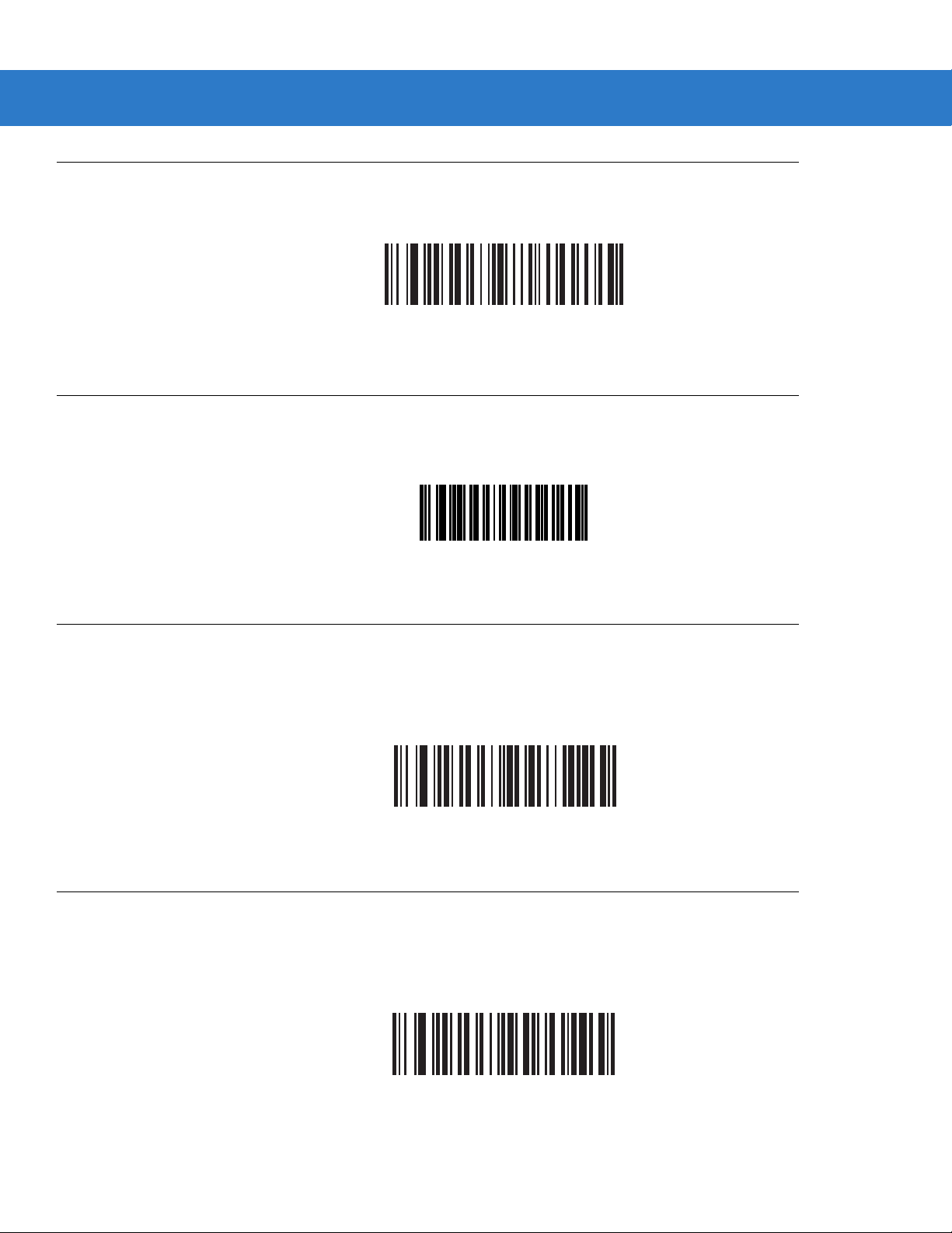
Report Scanner Version
Scan the bar code below to report the scanner’s software revision.
Report Scan Engine Version
Scan the bar code below to report the scan engine’s software revision.
User Preferences 5 - 19
Report Scanner Software Version
Report MIMIC Version
Scan the bar code below to report the MIMIC software revision installed in the cradle’s softwar e. Scanners that do
not use MIMIC architecture report nothing.
Report Synapse Cable
Scan the bar code below to report the software revision of the attached Synapse cable. If the scanner does not
detect an attached Synapse cable, it reports Synapse not attached.
Report Scan Engine Software Version
Report MIMIC Software Version
Report Synapse Cable
Page 94

5 - 20 Symbol LS3578 Product Reference Guide
Page 95

Chapter 6 Keyboard Wedge Interface
Introduction
This chapter provides instructions for programming the scanner for keyboard wedge host interface, used to
connect the scanner between the keyboard and host computer. The scanner translates the bar code data into
keystrokes, and transmits the information to the host computer via the cradle interface. The host computer accept s
the keystrokes as if they originated from the keyboard.
This interface adds bar code reading functionality to a system designed for manual keyboard input. In this mode
the keyboard keystrokes are simply passed through.
Throughout the programming bar code menus, default values are indicated with asterisks (
* Indicates Default
*North American
Feature/Option
*).
Page 96

6 - 2 Symbol LS3578 Product Reference Guide
Connecting a Keyboard Wedge Interface
Male DIN Host Connector
Keyboard
Connector
Female DIN Keyboard
Connector
Y-cable
Figure 6-1
Keyboard Wedge Interface Connection with Y-cable
To connect the keyboard wedge interface Y-cable:
1. Turn off the host and unplug the keyboard connector.
2. Attach the modular connector of the Y-cable to the cable interface port on the cradle. See Connecting the
Cradle on page 1-4.
3. Connect the round male DIN host connector of the Y-cable to the keyboard port on the host.
4. Connect the round female DIN keyboard connector of the Y-cable to the keyboard connector.
5. If required, connect the power supply to the cradle.
6. Ensure that all connections are secure.
7. Turn on the host system.
8. Pair the scanner to the cradle by scanning the bar code on the cradle.
9. Select the keyboard wedge host type by scanning the appropriate bar code from Ke yboard W edg e Host Types
on page 6-4.
10. To modify any other parameter options, scan the appropriate bar codes in this chapter.
11. Connect an external power supply if desired.
NOTE Interface cables vary depending on configuration. The connectors illustrated in Figure 6-1 are examples
only. The connectors may be different from those illustrated, but the steps to connect the cradle remain
the same.
Page 97

NOTE Disconnect the power supply before changing host cables or the scanner may not recognize the new host.
Keyboard Wedge Default Parameters
Table 6-1 lists the defaults for keyboard wedge host parameters. To change any option, scan the appropriate bar
code(s) provided in this chapter.
NOTE See Appendix A, Standard Default Parameters for all user preference, host, symbology, and
miscellaneous default parameters.
Keyboard Wedge Interface 6 - 3
Table 6-1
Keyboard Wedge Host Parameters
Keyboard Wedge Host Type IBM PC/AT& IBM PC Compatibles 6-4
Keyboard Wedge Country Types
(Country Codes)
Ignore Unknown Characters Enable 6-7
Keystroke Delay 0 msec (No Delay) 6-7
Intra-Keystroke Delay Disable 6-8
Alternate Numeric Keypad Emulation Disable 6-8
Caps Lock On Disable 6-9
Caps Lock Override Disable 6-9
Convert Wedge Data Do Not Convert Wedge Data 6-10
Function Key Mapping Disable 6-10
FN1 Substitution Disable 6-11
Keyboard Wedge Host Default Table
Parameter Default
North American 6-5
Page
Number
Send Make and Break Send Make and Break Scan
Codes
6-11
Page 98

6 - 4 Symbol LS3578 Product Reference Guide
Keyboard Wedge Host Types
Keyboard Wedge Host Types
Select the keyboard wedge host by scanning one of the following bar codes.
*IBM PC/AT & IBM PC Compatibles
IBM AT NOTEBOOK
NCR 7052
Page 99

Keyboard Wedge Interface 6 - 5
Keyboard Wedge Country Types (Country Codes)
Scan the bar code corresponding to the keyboard type. If the particular keyboard type is not listed, see Alternate
Numeric Keypad Emulation on page 6-8.
*North American
German Windows
French Windows
French Canadian Windows 95/98
French Canadian Windows XP/2000
French Belgian Windows
Page 100

6 - 6 Symbol LS3578 Product Reference Guide
Keyboard Wedge Country Types (Country Codes) (continued)
Spanish Windows
Italian Windows
Swedish Windows
UK English Windows
Japanese Windows
Brazilian-Portuguese Windows
 Loading...