

Page 1

8515 VEHICLE-MOUNT
COMPUTER
USER GUIDE
Page 2

Page 3

i
8515 VEHICLE-MOUNT COMPUTER
USER GUIDE
8000132-001
Revision A
April 2015
Page 4

ii 8515 Vehicle-Mount Computer User Guide
Copyright
No part of this publication may be reproduced or used in any form, or by any electrical or mechanical means,
without permission in writing from us. This includes electronic or mechanical means, such as photocopying,
recording, or information storage and retrieval systems. The material in this manual is subject to change
without notice.
The software is provided strictly on an “as is” basis. All software, including firmware, furnished to the user is on
a licensed basis. We grants to the user a non-transferable and non-exclusive license to use each software or
firmware program delivered hereunder (licensed program). Except as noted below, such license may not be
assigned, sublicensed, or otherwise transferred by the user without prior written consent from us. No right to
copy a licensed program in whole or in part is granted, except as permitted under copyright law. The user shall
not modify, merge, or incorporate any form or portion of a licensed program with other program material, create
a derivative work from a licensed program, or use a licensed program in a network without written permission
from us. The user agrees to maintain our copyright notice on the licensed programs delivered hereunder, and
to include the same on any authorized copies it makes, in whole or in part. The user agrees not to decompile,
disassemble, decode, or reverse engineer any licensed program delivered to the user or any portion thereof.
We reserves the right to make changes to any software or product to improve reliability, function, or design.
We do not assume any product liability arising out of, or in connection with, the application or use of any
product, circuit, or application described herein.
No license is granted, either expressly or by implication, estoppel, or otherwise under any of our intellectual
property rights. An implied license only exists for equipment, circuits, and subsystems contained in our
products.
Disclaimer
Every effort has been made to make this material complete, accurate, and up-to-date. In addition, changes are
periodically incorporated into new editions of the publication.
We reserve the right to make improvements and/or changes in the product(s) and/or the program(s) described
in this document without notice, and shall not be responsible for any damages including, but not limited to,
consequential damages, caused by reliance on the material presented.
Zebra and the Zebra head graphic are registered trademarks of ZIH Corp. The Symbol logo is a registered
trademark of Symbol Technologies, Inc., a Zebra Technologies company.
Workabout Pro4 and the names of other products and services provided by us are trademarks of ours.
Windows® and the Windows Logo are trademarks or registered trademarks of Microsoft Corporation in the
United States and/or other countries.
The Bluetooth® word mark and logos are owned by Bluetooth SIG, Inc. and any use of such marks by us is
under license.
All trademarks used herein are the property of their respective owners.
Page 5

Revision History
Changes to the original guide are listed below:
Change Date Description
-001 Rev A 04/2015 Rebrand for Zebra.
iii
Page 6

Page 7

TABLE OF CONTENTS
Table of Contents
Approvals and Safety Summary
CE Marking ..................................................................................................................................... xi
R&TTE Directive 1999/5/EC ........................................................................................................... xi
FCC Information to Users ............................................................................................................... xii
Emissions Information for Canada.................................................................................................. xiii
Warnings to Users .......................................................................................................................... xiv
China Regulatory Information ......................................................................................................... xv
About This Guide
About This Guide ............................................................................................................................ xvii
Text Conventions ............................................................................................................................ xviii
About the 8515 Vehicle-Mount Computer ...................................................................................... xviii
Chapter 1: Basic Checkout
Features of the 8515....................................................................................................................... 1-1
Preparing the 8515 for Operation ................................................................................................... 1-2
8515 Safety Instructions ................................................................................................................. 1-2
Important Operating Instructions..................................................................................................... 1-3
Switching the 8515 On and Off....................................................................................................... 1-3
Calibrating the Touchscreen ........................................................................................................... 1-3
Data Transfer Between the 8515 and a PC ................................................................................... 1-4
Using Microsoft ActiveSync............................................................................................................1-4
Using Windows Vista......................................................................................................................1-5
Summit Client Utility (SCU) for 802.11b/g Radio ............................................................................ 1-5
Assigning the IP Address ...............................................................................................................1-5
Name Servers Tab..........................................................................................................................1-6
Using the SCU to Connect to the WLAN .......................................................................................1-7
SSID ................................................................................................................................... 1-7
EAP Type............................................................................................................................ 1-8
Encryption ........................................................................................................................... 1-8
Resetting the 8515 Vehicle-Mount Computer ................................................................................. 1-8
Page 8

vi 8515 Vehicle-Mount Computer User Guide
Chapter 2: Getting to Know the 8515
The Internal Backup Battery ........................................................................................................... 2-1
The Stylus ....................................................................................................................................... 2-1
The Keyboard ................................................................................................................................. 2-1
Modifier Keys..................................................................................................................................2-2
Activating Modifier Keys...................................................................................................... 2-2
Locking Modifier Keys......................................................................................................... 2-2
The Keys.........................................................................................................................................2-2
Function Keys and Macro Keys ...................................................................................................... 2-3
Function Keys.................................................................................................................................2-3
Macro Keys.....................................................................................................................................2-4
The Keypad Backlight.....................................................................................................................2-4
The Display..................................................................................................................................... 2-4
8515 Indicators ............................................................................................................................... 2-5
Power Indicator LED.......................................................................................................................2-5
Onscreen Indicators .......................................................................................................................2-5
Audio Indicators..............................................................................................................................2-6
Scanning......................................................................................................................................... 2-6
Scanning Techniques .....................................................................................................................2-6
Scan LED Indicators.......................................................................................................................2-7
Troubleshooting..............................................................................................................................2-7
Operating One Dimensional (1D) Laser Scanners ........................................................................2-7
Operating PDF Laser Scanners .....................................................................................................2-7
Monitoring the Network Connection................................................................................................ 2-7
General Maintenance ..................................................................................................................... 2-7
Ports................................................................................................................................................2-7
Caring for the Touchscreen ............................................................................................................2-8
Cleaning the 8515 ..........................................................................................................................2-8
Chapter 3: Windows Embedded CE 5.0
Navigating In Windows Embedded CE 5.0 and Applications ......................................................... 3-1
Navigating Using a Touchscreen and Stylus..................................................................................3-1
Navigating Using the Keyboard......................................................................................................3-2
Working With Files, Folders, and Programs ................................................................................... 3-2
The Startup Desktop ....................................................................................................................... 3-3
The Desktop Icons..........................................................................................................................3-3
The Taskbar ....................................................................................................................................3-4
Using the Taskbar ..................................................
Customizing the Taskbar..................................................................................................... 3-4
The Start Menu ............................................................................................................................... 3-5
The Desktop ...................................................................................................................................3-5
Security Level .................................................................................................................................3-6
Changing a Password......................................................................................................... 3-6
Configuring Security............................................................................................................ 3-6
Programs ........................................................................................................................................3-6
Shortcuts.........................................................................................................................................3-8
............................................................. 3-4
Page 9

Table of Contents vii
Settings........................................................................................................................................... 3-9
Run ................................................................................................................................................. 3-9
Shutdown........................................................................................................................................3-10
Using a Dialog Box ......................................................................................................................... 3-10
Chapter 4: Configuration
Remote Desktop Connection.......................................................................................................... 4-1
Pocket PC Compatibility ................................................................................................................. 4-1
The Control Panel........................................................................................................................... 4-1
Control Panel Icons......................................................................................................................... 4-2
Control Panel Applications: Basic Setup......................................................................................... 4-5
App Launch Keys ...........................................................................................................................4-5
Certificates......................................................................................................................................4-6
Display Properties ..........................................................................................................................4-7
Background......................................................................................................................... 4-7
Appearance......................................................................................................................... 4-8
Backlight.............................................................................................................................. 4-8
Input Panel .....................................................................................................................................4-10
Keyboard Properties.......................................................................................................................4-11
Key Repeat ......................................................................................................................... 4-11
Backlight.............................................................................................................................. 4-12
One Shots ........................................................................................................................... 4-12
Macro Keys ......................................................................................................................... 4-13
Unicode Mapping ................................................................................................................4-15
Scancode Remapping......................................................................................................... 4-16
Virtual Key, Function, and Macro ........................................................................................ 4-17
Lock Sequence ................................................................................................................... 4-17
Manage Triggers ............................................................................................................................4-18
Trigger Mappings ................................................................................................................ 4-19
Add and Edit Trigger Mapping ............................................................................................ 4-19
Power Properties............................................................................................................................4-20
Battery................................................................................................................................. 4-21
Suspend.............................................................................................................................. 4-21
Advanced Power Properties................................................................................................ 4-22
Devices ............................................................................................................................... 4-22
Stylus Properties.............................................................................................................................4-22
Setting Double-Tap Sensitivity ............................................................................................ 4-23
T
ouchscreen Calibration...................................................................................................... 4-23
Disabling the Touchscreen .................................................................................................. 4-24
Volume and Sound Properties ......................................................................................................4-24
Volume Adjustments ........................................................................................................... 4-24
Bluetooth Setup ............................................................................................................................. 4-24
The Devices Tab............................................................................................................................. 4-25
Scan.................................................................................................................................... 4-25
Services .............................................................................................................................. 4-26
Set PIN................................................................................................................................ 4-27
The Servers Tab ............................................................................................................................. 4-27
Outgoing Tab ..................................................................................................................................4-28
Page 10

viii 8515 Vehicle-Mount Computer User Guide
Active Connections Tab..................................................................................................................4-29
Properties Tab.................................................................................................................................4-29
IPv6 Support ................................................................................................................................... 4-30
Scanner Settings ............................................................................................................................ 4-30
Decoded Scanners.........................................................................................................................4-30
Scanner Settings Options Tab........................................................................................................4-31
Double Click........................................................................................................................ 4-31
Display ................................................................................................................................ 4-31
Translations Tab .............................................................................................................................4-32
Case Rules ......................................................................................................................... 4-33
Ports Tab.........................................................................................................................................4-33
Serial Port (COM 1) ............................................................................................................4-34
SNMP (Simple Network Management Protocol) Setup .................................................................. 4-35
Contacts Tab...................................................................................................................................4-36
Communities Tab............................................................................................................................4-36
Enable SNMP ..................................................................................................................... 4-36
Adding a Community........................................................................................................... 4-36
Modifying a Community Setting .......................................................................................... 4-37
Removing an Existing Community...................................................................................... 4-37
Trap Destination Tab.......................................................................................................................4-37
Enabling Authentication TRAPS ......................................................................................... 4-38
Adding a Destination...........................................................................................................4-38
Changing a Destination....................................................................................................... 4-38
Removing a Trap Destination.............................................................................................. 4-38
Permitted Hosts Tab .......................................................................................................................4-39
Adding a Host ..................................................................................................................... 4-39
Changing a Host ................................................................................................................. 4-39
Storage Manager ............................................................................................................................ 4-39
Formatting a Memory Card ............................................................................................................4-40
Creating Partitions ..........................................................................................................................4-40
Partition Management ....................................................................................................................4-41
Dismounting a Partition....................................................................................................... 4-41
Deleting a Partition.............................................................................................................. 4-41
Formatting a Partition.......................................................................................................... 4-41
Mounting a Partition ............................................................................................................ 4-42
Total Recall .............................................................................................................................
Creating a Backup Profile...............................................................................................................4-43
Profile Information............................................................................................................... 4-43
Add Files ............................................................................................................................. 4-44
View Selections................................................................................................................... 4-45
Performing the Backup ....................................................................................................... 4-45
Restoring a Profile ..........................................................................................................................4-45
TweakIT Settings ............................................................................................................................ 4-46
Advanced........................................................................................................................................4-46
Advanced Interface and Network........................................................................................ 4-46
Advanced Services Settings ............................................................................................... 4-47
Advanced Intermediate Driver ............................................................................................ 4-47
Radio Features ................................................................................................................... 4-48
........ 4-42
Page 11

Table of Contents ix
User ................................................................................................................................................ 4-48
Internet Explorer Settings.................................................................................................... 4-48
User Display Settings..........................................................................................................4-49
Registry Editor ................................................................................................................................4-49
Chapter 5: Peripheral Devices & 8515 Installations
External Bar Code Readers............................................................................................................ 5-1
Entering Data with the Bar Code Reader....................................................................................... 5-1
Bluetooth Peripherals .................................................................................................................... 5-1
Linking an 8515 to an Ethernet Network.........................................................................................5-2
Network Access.............................................................................................................................. 5-2
8515 Mounting Accessories: Installing the RAM Mounting Kit........................................................ 5-2
Component Part Numbers .............................................................................................................5-3
MT33XX RAM Mounting Kit Specifications....................................................................................5-4
Preparation .....................................................................................................................................5-5
Installation....................................................................................................................................... 5-7
RAM Vesa Base..................................................................................................................5-8
RAM Circular Base .............................................................................................................5-8
Positioning the 8515.......................................................................................................................5-8
Optional Mount Kits ........................................................................................................................5-9
MT3250 Quick Release Mount “Turn & Lock”................................................................................. 5-10
8515 Vehicle-Mount Computer Installations ................................................................................... 5-10
Wiring Guidelines ...........................................................................................................................5-10
Non-Vehicle Installations................................................................................................................5-11
Wiring Vehicle Power to the 8515..................................................................................................5-11
Installing the Power Pre-regulator....................................................................................... 5-11
Chapter 6: Specifications
8515 Vehicle-Mount Computer Specifications ................................................................................ 6-1
Colour Display................................................................................................................................. 6-2
Keyboard......................................................................................................................................... 6-2
External Power................................................................................................................................ 6-3
Internal Lithium-Polymer Battery..................................................................................................... 6-3
Radio Specifications........................................................................................................................ 6-3
External Bar Code Scanners .......................................................................................................... 6-3
Appendix A: Port Pinouts
Serial Port Interface Pinout (DB-9 male)......................................................................................... A-1
Enhanced USB1 Port Interface Pinout............................................................................................A-2
Enhanced USB2 Port Interface Pinout...................................
Appendix B: SCU for 802.11b/g Radio
SCU Tabs........................................................................................................................................ B-1
Main ......................................................................................................................................... B-1
Profile........................................................................................................................................ B-2
.........................................................A-2
Page 12

x 8515 Vehicle-Mount Computer User Guide
Status ....................................................................................................................................... B-5
Diags ........................................................................................................................................ B-6
Global ....................................................................................................................................... B-6
Appendix C: USB Setup Application
USB Setup ...................................................................................................................................... C-1
Launching the Application......................................................................................................... C-1
Installation Complete ................................................................................................................ C-2
Index............................................................................................................ I
Page 13

APPROVALS AND SAFETY SUMMARY
APPROVALS AND SAFETY SUMMARY
CE Marking
When used in a residential, commercial or light industrial environment the product and its approved UK and
European peripherals fulfil all requirements for CE marking.
R&TTE Directive 1999/5/EC
This equipment complies with the essential requirements of EU Directive 1999/5/EC (Declaration available:
www.psion.com).
Cet équipement est conforme aux principales caractéristiques définies dans la Directive européenne RTTE
1999/5/CE. (Déclaration disponible sur le site: www.psion.com).
Die Geräte erfüllen die grundlegenden Anforderungen der RTTE-Richtlinie (1999/5/EG). (Den Wortlaut der
Richtlinie finden Sie unter: www.psion.com).
Questa apparecchiatura è conforme ai requisiti essenziali della Direttiva Europea R&TTE 1999/5/CE. (Dichiarazione disponibile sul sito: www.psion.com).
Este equipo cumple los requisitos principales de la Directiva 1995/5/CE de la UE, “Equipos de Terminales de
Radio y Telecomu-nicaciones”. (Declaración disponible en: www.psion.com).
Este equipamento cumpre os requisitos essenciais da Directiva 1999/5/CE do Parlamento Europeu e do
Conselho (Directiva RTT). (Declaração disponível no endereço: www.psion.com).
Ο εξοπλισμός αυτός πληροί τις βασικές απαιτήσεις της κοινοτικής οδηγίας EU R&TTE 1999/5/EΚ. (Η δήλωση
συμμόρφωσης διατίθεται στη διεύθυνση: www.psion.com)
Deze apparatuur voldoet aan de noodzakelijke vereisten van EU-richtlijn betreffende radioapparatuur en telecommunicatie-eindappa-ratuur 199/5/EG. (verklaring beschikbaar: www.psion.com).
Dette udstyr opfylder de Væsentlige krav i EU's direktiv 1999/5/EC om Radio- og teleterminaludstyr. (Erklæring
findes på: www.psion.com).
Dette utstyret er i overensstemmelse med hovedkravene i R&TTE-direktivet (1999/5/EC) fra EU. (Erklæring
finnes på: www.psion.com).
Page 14

xii 8515 Vehicle-Mount Computer User Guide
Utrustningen uppfyller kraven för EU-direktivet 1999/5/EC om ansluten teleutrustning och ömsesidigt erkännande av utrustningens överensstämmelse (R&TTE). (Förklaringen finns att läsa på: www.psion.com).
Tämä laite vastaa EU:n radio- ja telepäätelaitedirektiivin (EU R&TTE Directive 1999/5/EC) vaatimuksia. (Julkilausuma nähtävillä osoitteessa: www.psion.com).
Psion tímto prohlašuje, že 8515 Vehicle-Mount Computer je ve shodě se základními požadavky a dalšími
příslušnými ustanoveními směrnice 1995/5/ES (NV č. 426/2000 Sb.) a Prohlášení o shodě je k dispozici na
www.psion.com.
Toto zarízení lze provozovat v České republice na základě generální licence č. GL-12/R/2000.
Psion týmto vyhlasuje, že 8515 Vehicle-Mount Computer spĺňa základné požiadavky a všetky príslušné ustanovenia Smernice 1995/5/ES (NV č. 443/2001 Z.z.) a Vyhlásenie o zhode je k dispozícii na www.psion.com.
Toto zariadenie je možné prevádzkovat’ v Slovenskej republike na základe Všeobecného povolenia č.
VPR-01/2001.
FCC Information to Users
Federal Communication Commission Interference Statement
This equipment has been tested and found to comply with the limits for a Class B digital device, pursuant to
Part 15 of the FCC Rules. These limits are designed to provide reasonable protection against harmful interference in a residential installation. This equipment generates, uses and can radiate radio frequency energy and,
if not installed and used in accordance with the instructions, may cause harmful interference to radio communications. However, there is no guarantee that interference will not occur in a particular installation.
If this equipment does cause harmful interference to radio or television reception, which can be determined by
turning the equipment off and on, the user is encouraged to try to correct the interference by one of the
following measures:
• Reorient or relocate the receiving antenna.
• Increase the separation between the equipment and receiver.
• Connect the equipment into an outlet on a circuit different from that to which the receiver is connected.
• Consult the dealer or an experienced radio/TV technician for help.
This device complies with Part 15 of the FCC Rules. Operation is subject to the following two conditions:
1. This device may not cause harmful interference, and
2. This device must accept any interference received, including interference that may cause
undesired operation.
FCC Caution:
Any changes or modifications not expressly approved by the party responsible for compliance could void the
user's authority to operate this equipment.
Page 15

IMPORTANT FCC Radiation Exposure Statement
This transmitter must not be co-located or operating in conjunction with any other
antenna or transmitter., except as noted here:
The condition for the co-location of the Bluetooth® and Model RA2040/RA2041
radios is as follows:
The Murata Bluetooth® radio must use the Antenova antenna
(P/N 3030A5645-01).
The Model RA2040/RA2041 radios must use one of these antennas:
1. Radiall/Larsen Model EPA-016.
2. Integrated Antenna (P/N 1070545).
3. Mobile Mark Model IMAG5-2400.
The use of any other configuration requires its own FCC approval.
Some equipment in hospitals and aircraft are not shielded from radio frequency
energy. Do not use the 8515 onboard aircraft, or in hospitals, without first obtaining permission.
Approvals and Safety Summary xiii
Do not use near pacemakers. The product may affect the operation of some medically implanted devices such as pacemakers, causing them to malfunction. Avoid
placing your product next to such devices. Keep a minimum distance of 20 cm
between the device and the product to reduce the risk of interference. If you have
any reason to suspect that interference is taking place, turn off the 8515 and
contact your cardiologist for assistance.
NOTE In August 1996 the Federal Communications Commission (FCC) of the US adopted an
updated safety standard for human exposure to radio frequency energy emitted by FCC regulated transmitters. The design of this product complies with the FCC guidelines and those
standards. To maintain compliance with the FCC RF exposure guidelines, ensure the
antenna is at least 20 cm from your body when transmitting.
Emissions Information for Canada
This Class B digital apparatus meets all requirements of the Canadian Interference-Causing Equipment Regulations. When using the 802.11 radio option, to prevent radio interference, this device is intended to be operated indoors and away from windows to provide maximum shielding. Equipment (or its transmit antenna) that
is installed outdoors is subject to licensing.
Cet appareil numérique de la classe B respecte toutes les exigences du Règlement sur le matériel brouilleur
du Canada. En cas d’utilisation du module radio 802.11, afin d'éviter toute interférence radio avec le service
autorisé, l'appareil doit être utilisé à l'intérieur, tout en tant éloigné de toute fenêtre afin de garantir le maximum
de protection. Si cet équipement (ou son antenne émettrice) est installé à l'extérieur, il est alors soumis
à licence.
Page 16

xiv 8515 Vehicle-Mount Computer User Guide
Warnings to Users
IMPORTA NT For your own safety, it is critical that you comply with the following warnings.
RF Exposure
To satisfy FCC RF exposure requirements for vehicle mount transmitting devices, a separation distance of 20
centimeters should be maintained between the antenna of this device and persons during device operation. To
ensure compliance, operations at closer than this distance is not recommended.
Do Not Remove Covers or Open Enclosures
To avoid injury, the equipment covers and enclosures should only be removed by qualified service personnel.
Do not operate the equipment without the covers and enclosures properly installed.
Batteries
• Risk of explosion if battery is replaced by an incorrect type.
• Dispose of used batteries according to the instructions.
Cautions
• Use of the Vehicle Mount Computer while charging the fork truck battery is prohibited.
• Use of additional wiring and attachments not recommended or sold by the manufacturer may result in fire,
electric shock or personal injury.
• If using an AC adaptor, use only the AC adaptor recommended by manufacturer.
• Do not operate the vehicle-mount computer with a damaged cord or plug. Replace immediately.
• Make sure the cord is positioned so that it is not stepped on, tripped over or otherwise subjected to
damage or stress.
• An extension cord should not be used unless absolutely necessary. Use of an improper extension cord
could result in fire or electric shock.
• To reduce risk of electric shock, unplug the vehicle-mount computer from the DC source before attempting
any maintenance or cleaning.
WARNING! Physically disconnect the 8515 from the vehicle battery during battery
charging (into AC outlet).
Country Roaming
This device incorporates the International Roaming feature (IEEE802.11d) which will ensure the product operates on the correct channels for the particular country of use.
Ad-Hoc Operation (2.4 GHz band)
Ad-Hoc operation is limited to Channels 1-11 (2412-2462 MHz).
Page 17

China Regulatory Information
通过访问以下网址可下载当地语言支持的产品说明书
http://www.zebra.com/CN-ZH/Pages/Contact_Us#support_tab
Approvals and Safety Summary xv
Page 18

Page 19

ABOUT THIS GUIDE
ABOUT THIS GUIDE
About This Guide
This guide describes how to configure, operate and maintain the 8515 Vehicle-Mount Computer.
Chapter : Approvals and Safety Summary. provides a summary of the approvals and safety for the 8515.
Chapter : About This Guide. provides a basic overview of the 8515 Vehicle-Mount Computer User Guide.
Chapter 1: Basic Checkout. describes the steps required to get the 8515 ready for operation.
Chapter 2: Getting to Know the 8515. describes the 8515 features and provides a description of the key-
board, display, indicators, etc
Chapter 3: Windows Embedded CE 5.0. describes the Microsoft® Windows® Embedded CE 5.0 desktop
and how to use it. This chapter also outlines the basics of moving around a Windows Embedded
CE 5.0 window, selecting and opening icons and files, and working with a dialog box.
Chapter 4: Configuration. provides a description of the Windows Embedded CE 5.0 Control Panel and how
to use it to configure the 8515, along with the scanners attached to the unit.
Chapter 5: Peripheral Devices & 8515 Installations. describes the peripherals and accessories available for
your 8515.
Chapter 6: Specifications. details the 8515 Vehicle-Mount Computer, radio, and battery specifications.
Appendix A: Port Pinouts. provides the 8515 Vehicle-Mount Computer pinouts.
Appendix B: SCU for 802.11b/g Radio. provides details on the Summit Client Utility (SCU), which is used to
configure the Summit RA2041 802.11b/g Compact Flash radio module.
Appendix C: USB Setup Application. describes the USB setup application.
Page 20

xviii 8515 Vehicle-Mount Computer User Guide
Text Conventions
NOTE Notes highlight additional helpful information.
IMPORTANT These statements provide particularly important instructions or additional information
that is critical to the operation of the equipment.
WARNING! These statements provide critical information that may prevent physical injury,
equipment damage or data loss.
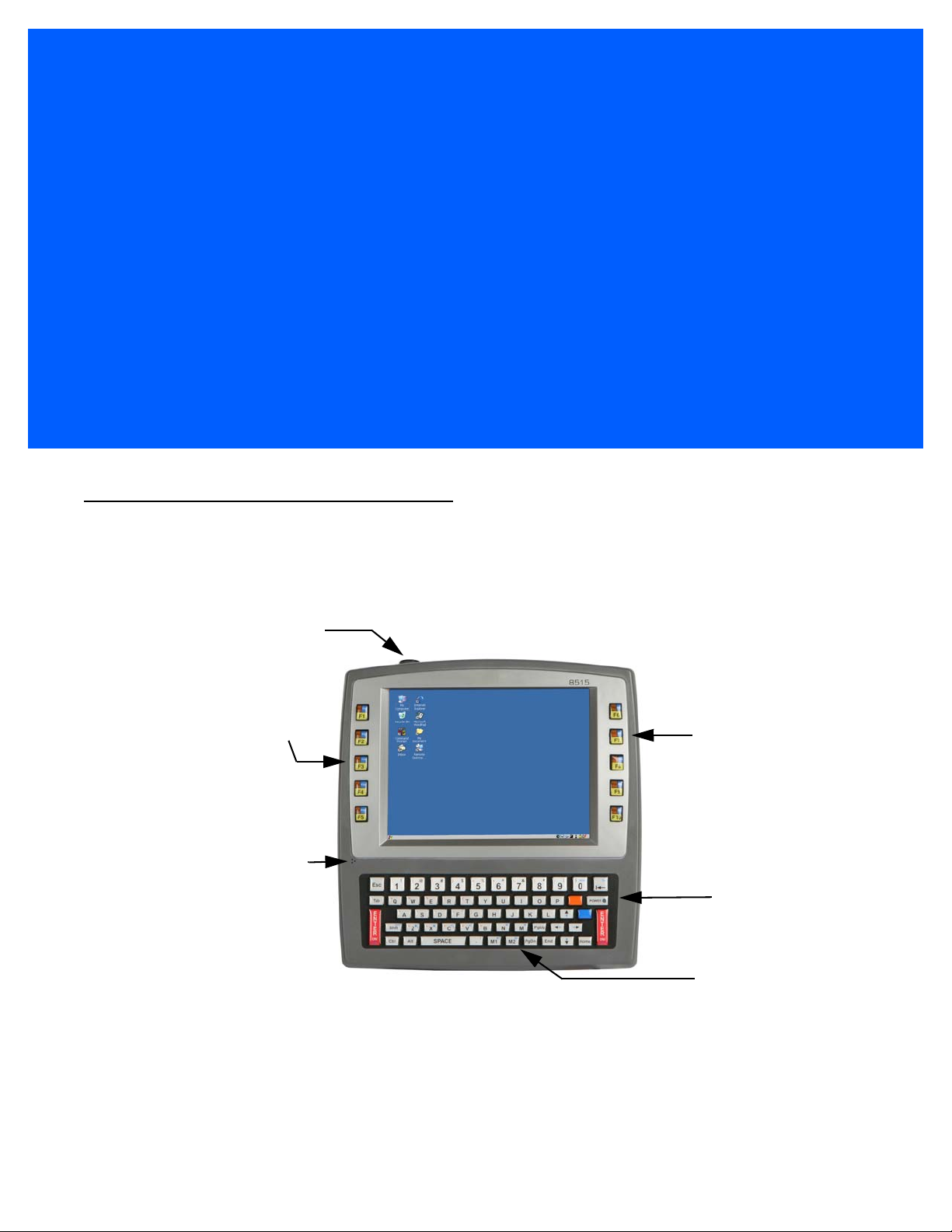
About the 8515 Vehicle-Mount Computer
The 8515 is a ruggedized vehicle-mount computer, running the Microsoft Windows Embedded CE 5.0 operating system. It is intended for use in commercial and industrial applications with a focus on real time wireless
data transactions. A wide range of data input capabilities are supported through a variety of imager, RFID and
bar code scanner options.
Figure 1
8515 with Qwerty Keyboard
Page 21
CHAPTER 1 BASIC CHECKOUT
Power LED
Function Keys
Function Keys
Macro Keys
Beeper
Antenna
BASIC CHECKOUT 1
Features of the 8515
Figure 1-1
Front of the 8515 Vehicle-Mount Computer
Page 22
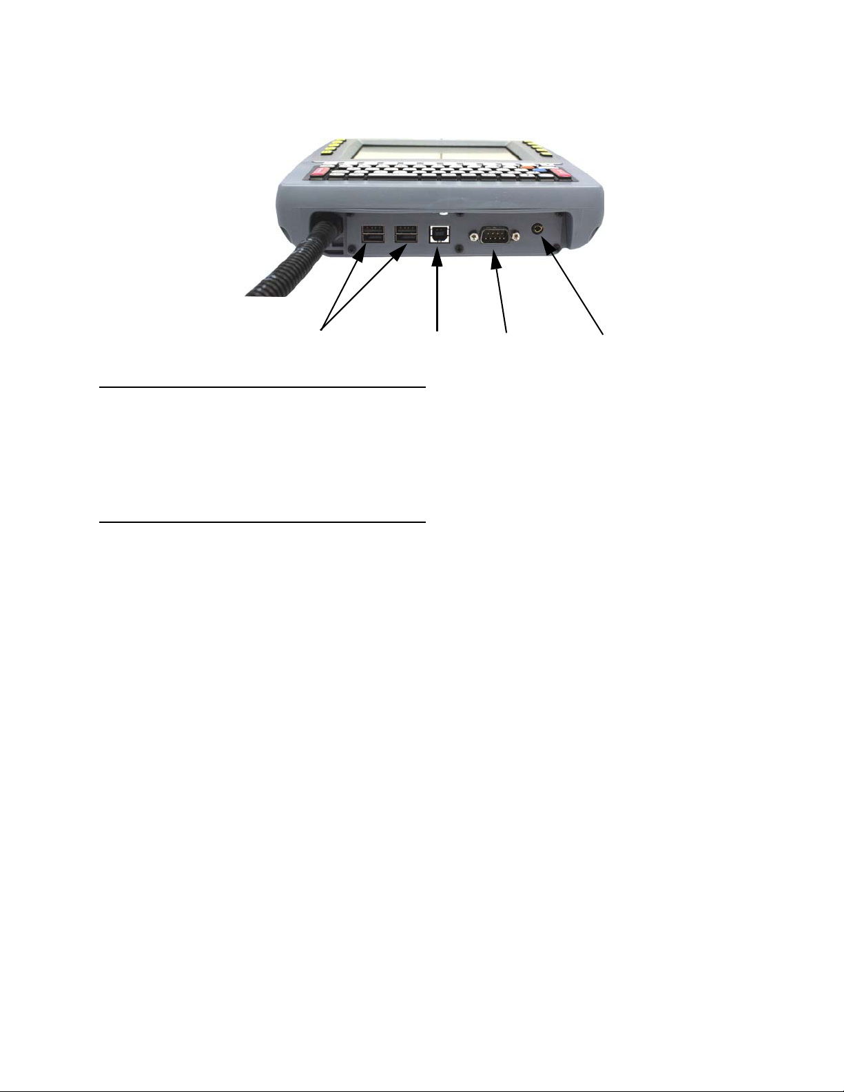
Figure 1-2
UART (DB-9) Port
USB Device Port
Enhanced USB Host Ports
Speaker/Mic Jack
(for external devices, console)
8515 Ports
Preparing the 8515 for Operation
Typically the 8515 Vehicle-Mount Computer is configured at the factory and arrives ready for
use. Although the 8515 is equipped with an internal Compact Flash slot and a Micro-SD I/O
slot, these slots are not intended for user modification. If a device needs to be changed or
added in these slots, contact qualified personnel.
8515 Safety Instructions
• The cord should be installed in the vehicle so that it is not subjected to damage or stress.
• Use of a power cord that is not recommended or sold by the manufacturer may result in fire,
electric shock, or personal injury.
• An extension cord should not be used unless absolutely necessary. Use of an improper
extension cord could result in fire or electric shock. If an extension cord must be used,
make sure:
• The plug pins on the extension cord are the same number, size, and shape as those on the
adaptor.
• The extension cord is properly wired and in good electrical condition and that the wire size
is larger than 16 AWG.
• When the unit is connected to the battery or AC adaptor, the mains power cord shall comply
with National safety regulations of the country where the equipment is to be used.
• Do not use the AC adaptor with a damaged cord or plug. Replace it immediately.
• Do not operate the AC adaptor if it has received a sharp blow, been dropped, or otherwise
damaged in any way; it should be inspected by qualified service personnel.
• Do not disassemble the AC adaptor; it should be repaired by qualified service personnel.
Incorrect reassembly may result in electric shock or fire.
• To reduce risk of electric shock, unplug the battery or AC adaptor from the outlet before
attempting any maintenance or cleaning.
• Do not expose the battery or AC adaptor to rain or snow.
Page 23
Important Operating Instructions
WARNING! IT IS CRITICAL that this information be reviewed and that any guidelines applicable
to your 8515 be strictly followed.
Backup Battery
The computer backup battery provides one hour of memory backup. The capacity is reduced as the operating
temperature cools. The table below provides a general outline of battery capacity based on the operating
temperature. Charging of the backup battery will occur between 0° C and 40° C.
NOTE If the backup battery temperature is less than 10° C and a brown-out occurs, the display backlight
will switch off in order to maintain computer operations. The backlight will switch back on when
external power is restored or the battery temperature is above 10° C.
WARNING! Do not install the 8515 in such a way that the power cable is bent 90 degrees as this
may damage the power cable and power cable strain relief.
Basic Checkout 1 - 3
Switching the 8515 On and Off
• To switch on the 8515, press the [ENTER/ON] key.
NOTE If the 8515 is in suspend state, pressing [ENTER/ON] ‘wakes’ the unit from this state. The screen
in which you were working before the computer entered suspend state is displayed.
To switch off the 8515:
• Press the [BLUE] key, and then press the [ENTER/ON] key.
Turning off the 8515 does not result in a complete reboot; rather, the unit enters a power-saving, “suspend”
state. When the 8515 is turned on from suspend state, operation resumes within a few seconds.
IMPORTANT If the word BLUE is displayed in uppercase in the taskbar at the bottom of the screen,
this key is locked on — the 8515 will not switch off. Press the [BLUE] key again to unlock
it; then press [BLUE] [ENTER/ON] to switch the 8515 off.
If, however, you’ve disabled the Blue Key in the One Shot dialog box, the 8515 can be
turned off even when the [BLUE] key is locked on.
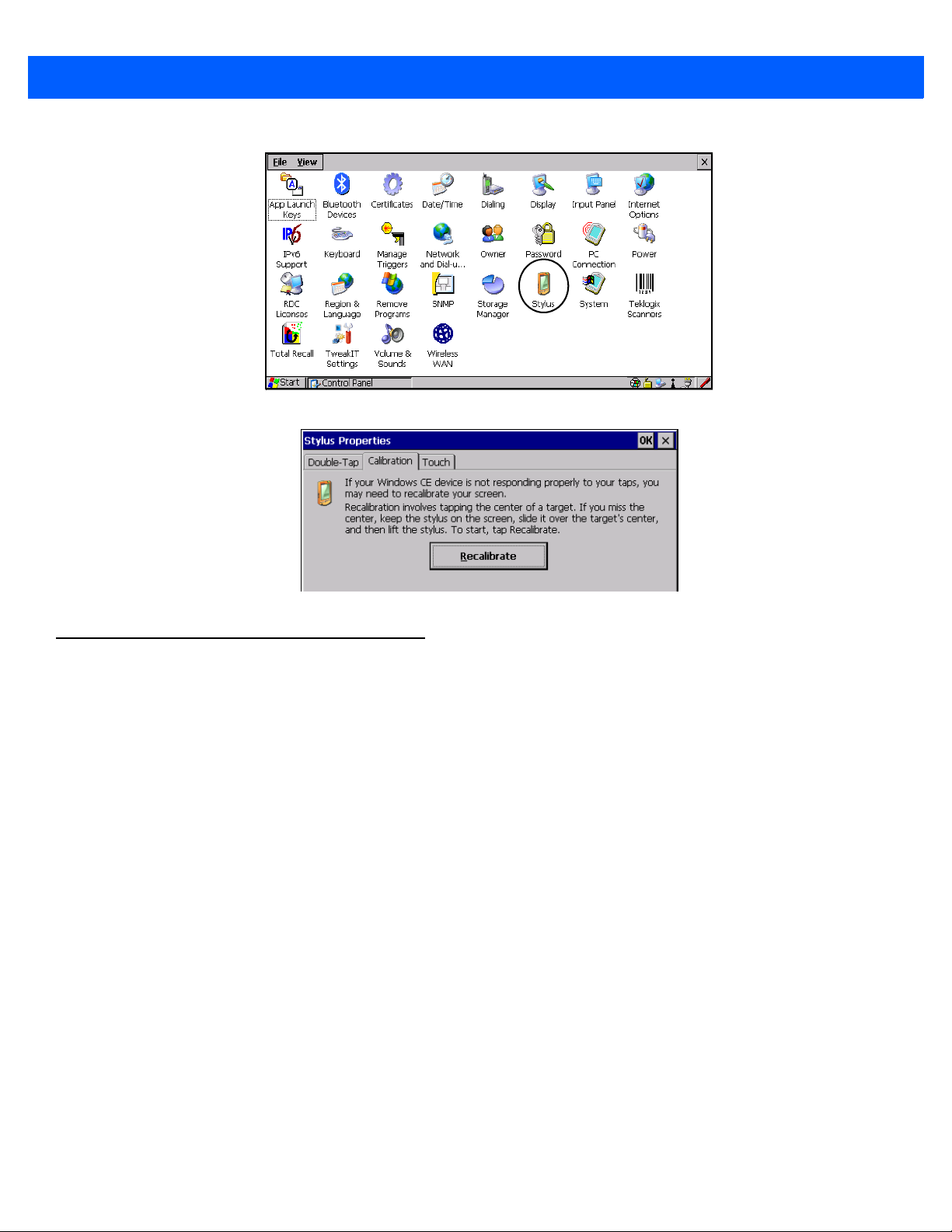
Calibrating the Touchscreen
If your 8515 touchscreen has never been calibrated or if you find that the stylus pointer is not accurate when
you tap on an item, use the Stylus Properties dialog box in the Control Panel to recalibrate the screen.
• In the Control Panel, choose the Stylus icon to display the Stylus Properties window.
Page 24
1 - 4 8515 Vehicle-Mount Computer User Guide
• Choose the Calibration tab, and then tap on the Recalibrate button.
• Follow the directions on the calibration screen to calibrate the screen.
Data Transfer Between the 8515 and a PC
Data transfer options vary slightly depending on the type of operating system installed in your PC.
For Windows XP SP2 operating systems or earlier, Microsoft
can be used to connect your 8515 to PCs running this software.
®
If the Windows Vista
between your 8515 and your PC.
By connecting the 8515 to a PC with a cable you can:
• View 8515 files from Windows Explorer.
• Drag and drop files between the 8515 and the PC in the same way that you would between PC drives.
• Back up 8515 files to the PC, then restore them from the PC to the hand-held again, if needed, and so on.
Using Microsoft ActiveSync
To install ActiveSync, follow the step-by-step instructions provided with the program’s setup wizard. Go to the
Microsoft Download Center for information about downloading ActiveSync.
operating system is installed in your PC, ActiveSync is not required to transfer data
®
ActiveSync® is PC connectivity software that
Page 25
NOTE When you use an RS-232 serial port to connect devices like the 8515 to your desktop computer,
the connection may not succeed because ActiveSync has trouble connecting at non-default
baud rates.
To workaround this problem, set the ActiveSync baud rate on the desktop to use the same baud
rate as the device. You can set the baud rate by editing the registry on the desktop host computer, as detailed in the steps outlined at the following website:
http://support.microsoft.com/kb/324466
Using Windows Vista
If you have Windows Vista, your 8515 data transfers do not require ActiveSync. To transfer data between your
PC and your 8515:
• Tap on Start>Computer to display the drives. Your 8515 will be visible here.
• Open drives, files and folders as you would on your PC.
Summit Client Utility (SCU) for 802.11b/g Radio
Basic Checkout 1 - 5
This section describes the Summit Client Utility (SCU). The SCU provides the utilities you will need to
configure the 802.11b/g Compact Flash radio module so that it can communicate through a wireless LAN effectively and securely.
NOTE You do not need to reset your 8515 after configuring the Summit DC 802.11 SC (Model RA2041)
CF radio.
Assigning the IP Address
Before launching the SCU, follow the steps below to determine how the IP address will be obtained — either
via DHCP or by specifying an address.
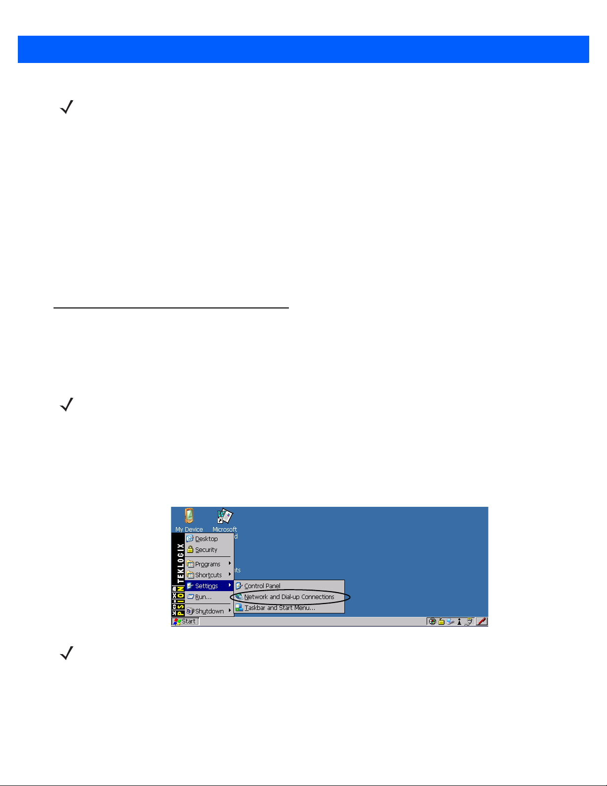
1. Tap on Start>Settings>Network and Dial-up Connections.
NOTE You can press [CTRL] [ESC] to display the Start Menu.
2. Choose the Summit WLAN Adapter icon to open the 802.11 Wireless LAN Settings window — in the
sample screen below, this is labelled “PTXCF838...”.
Page 26
1 - 6 8515 Vehicle-Mount Computer User Guide
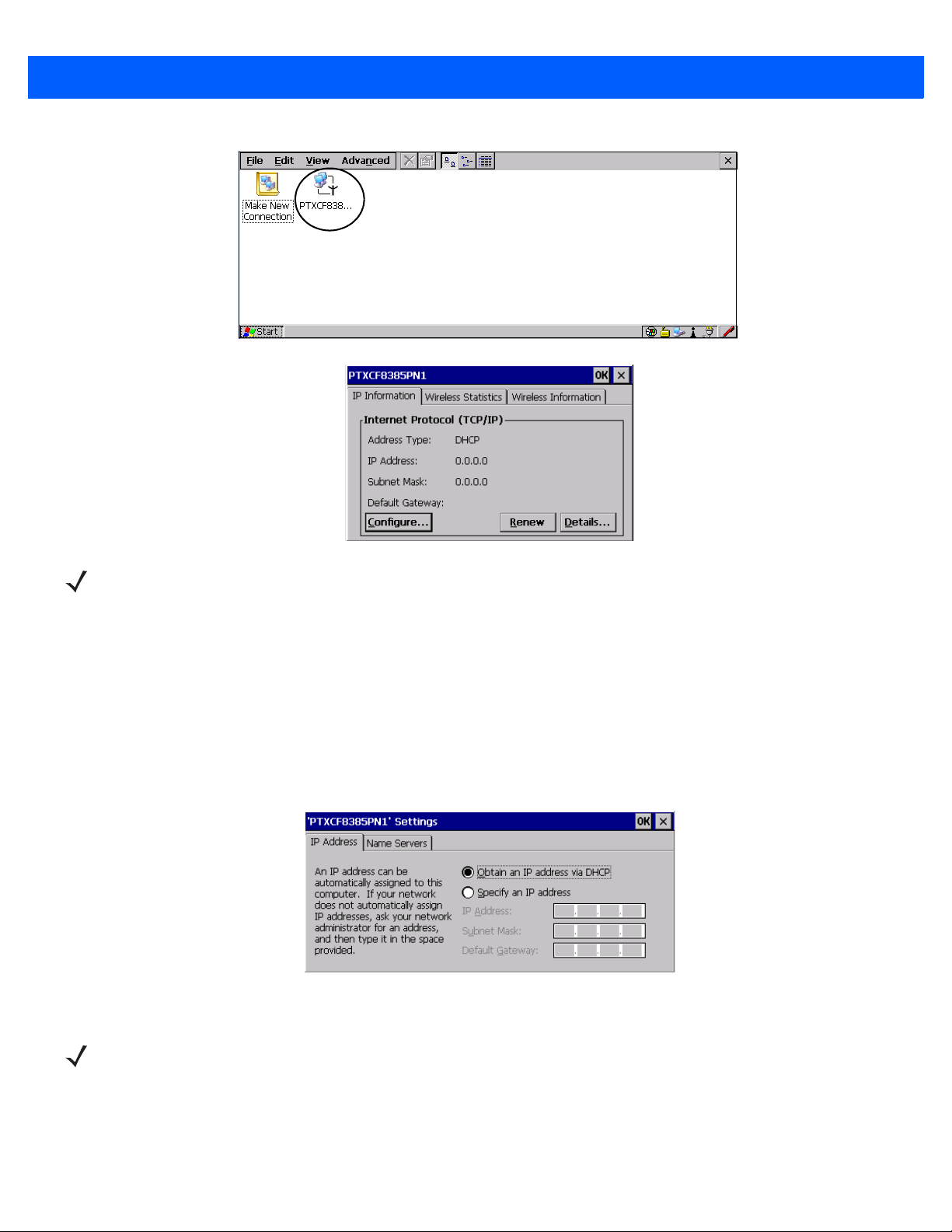
NOTE Choosing the Renew button forces the 8515 to renew or find a new IP address. This is useful if,
for example, you are out of communication range for a longer period of time and your 8515 is
dropped from the network.
3. Tap on the IP Information tab
4. To define a static IP address, tap the Configure button. The Summit WLAN Adapter Settings menu
provides two options:
• Tap on Obtain an IP address via DHCP to have an address assigned automatically, or
• If you want to use a particular IP address, tap on Specify an IP address, and type the preferred
address as well as the IP, Subnet Mask and Default Gateway addresses in the appropriate fields. Tap
OK to save your information.
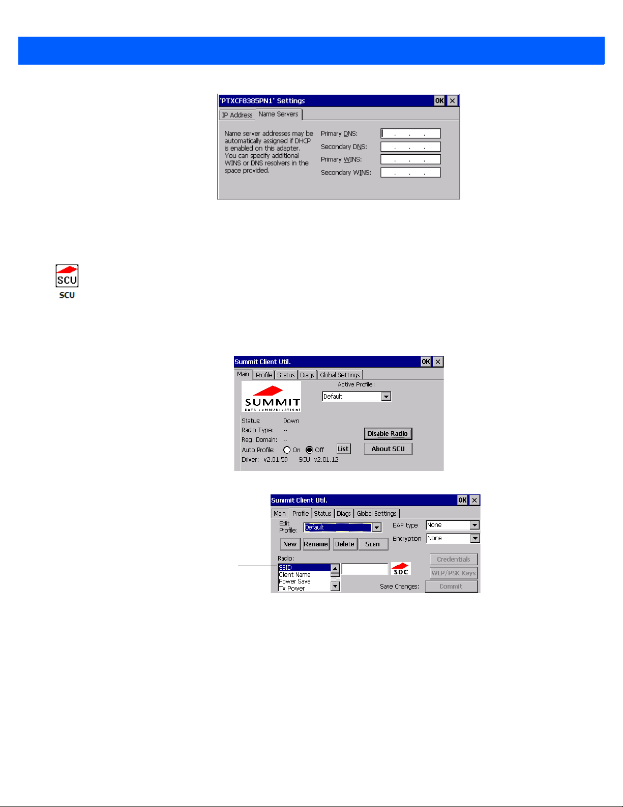
Name Servers Tab
NOTE If DHCP is enabled, name server addresses are assigned automatically.
• In the IP Information tab, tap on the Configure button.
• Tap on the Name Servers tab.
Page 27
Basic Checkout 1 - 7
Radio
Attributes
The DNS and WINS fields in the Name Servers tab allow you to specify additional WINS and DNS resolvers.
The format for these fields is ###.###.###.###.
Using the SCU to Connect to the WLAN
This section provides a quick set of steps to create a profile (referred to as a config). Detailed information about
each of the SCU tabs — Main, Config, Status, Diags and Global Settings — is provided in Appendix B: SCU for
802.11b/g Radio.
To launch the SCU so that your computer can connect to a wireless LAN:
1. Tap on Start>Programs>Summit>SCU.
2. Tap on the Profile tab.
3. Tap on the New button to define a new profile.
4. Type a name for your configuration using any alpha-numeric combination to uniquely identify this
profile.
5. Tap on OK to return to the Profile tab.
6. Tap on Commit to save the profile name.
7. When a pop-up message indicates that your configuration will be saved, tap on OK.
SSID
To configure the SSID for the network to which you want to associate:
• Type an SSID in the text box to the right of SSID. This field is limited to 32 characters.
Page 28

1 - 8 8515 Vehicle-Mount Computer User Guide
• Tap on Commit and then, in the pop-up message, tap on OK to save your SSID setting.
IMPORTANT To learn more about the other options available in the radio attributes list, refer to Profile
on page B-2.
EAP Type
• Tap on the EAP type drop-down menu, and choose the appropriate type of authentication — LEAP,
EAP-FAST, PEAP-MSCHAP, and PEAP-GTC.
• Next, tap on the Credentials button, and type credentials for IEEE 802.1X EAP types.
IMPORTANT Refer to SCU Security Capabilities on page B-3 for details about security settings. Addi-
tional EAP details are described in EAP Credentials on page B-4.
Encryption
• Tap on the Encryption drop-down menu, and choose the appropriate type of encryption — Manual WEP,
Auto WEP, WPA PSK, WPA TKIP, WAP2 PSK, WAP2 AES, CCKM TKIP, CKIP Manual, or CKIP Auto.
If you choose Manual WEP, WPA PSK or WPA PSK:
• Tap on the WEP/PSK Keys button. For Ma nu al WEP , choose up to four static WEP keys. For PSK, type
an ASCII passphrase or hex PSK.
• Configure any other settings that are supplied by the network administrator for the SSID to which you will
associate.
• Make certain that you tap on Commit following each change.
Once you’ve completed the configuration:
•Tap the Main tab. Tap on the Active Profile button – your new profile will be listed in the drop-down menu.
When you tap on the profile you created, the 802.11a/b/g radio module attempts to connect to the network
using the following steps:
• Associate to the SSID.
• Authenticate to the network.
• If EAP authentication is being used, derive dynamic encryption keys.
• If DHCP is being used by the network, obtain an IP address.
If the radio is not connecting properly:
• Tap on the Status tab.
The Status dialog box lists the IP and MAC addresses, and indicates the current state of the radio, the signal
strength, channel and so on.
You can go to the Diags tab for DHCP renewal, ICMP Echo Requests (Pings), and diagnostics.
Resetting the 8515 Vehicle-Mount Computer
Warm Reset
To execute a warm reset:
Page 29

1 - 9 8515 Vehicle-Mount Computer User Guide
• Press and hold down the [BLUE] key and the [ENTER/ON] key simultaneously for a minimum of
six seconds.
A warm reset closes open applications; any unsaved data is lost. Installed programs and saved data
are preserved.
NOTE You do not need to reset your 8515 after configuring the radio.
Cold Reset
There are two options when executing a cold reset: reset to BootLoader, or reset directly to Windows
Embedded CE 5.0 operating system.
To execute a cold reset and access the BooSt menu:
• Press and hold down the [BLUE] key, the [ENTER] key and the [SPACE] key simultaneously for a
minimum of six seconds.
After a cold reset, the BooSt menu appears.
• If you want to load the Windows Embedded CE 5.0 operating system, type 1.
• If you want a clean start, press ! (that is, [SHIFT] [1]). All data and settings are lost. Files and data stored in
flash are preserved.
Once the OS loads, any executables and cab files in the startup folders are run. The cab files are deleted by
the cab file installer unless they are marked read-only.
Page 30

Page 31

CHAPTER 2 GETTING TO KNOW THE 8515
GETTING TO KNOW THE 8515 2
The Internal Backup Battery
The 8515 Vehicle-Mount Computer is equipped with an internal battery that will provide backup power to the
unit for up to 30 seconds of normal operation. The display will be blank during this time. After 30 seconds, the
unit will shut off to preserve the contents of RAM. The backup battery provides one hour of memory backup.
For configuration information, please see Power Properties on page 4-20; for specifications, see Internal
Lithium-Polymer Battery on page 6-3.
The backup battery is not user accessible. It must be replaced by authorized personnel.
The Stylus
The stylus is supplied with a holder with double-sided adhesive tape so that it can be attached wherever is
most convenient for you.
The Keyboard
The 8515 provides a 58-key QWERTY or ABC alphanumeric keyboard layout.
Most of the keys on these keyboards operate much like a desktop computer. If a key or key function is not
consistent with the PC keyboard, the differences are noted.
Page 32

2 - 2 8515 Vehicle-Mount Computer User Guide
NOTE A soft keyboard that is a replica of the external keyboard is available. Refer to Input
Panel on page 4-3 for details.
Modifier Keys
The [SHIFT], [CTRL], [ALT], [BLUE] ad [ORANGE] keys are modifier keys. Pressing a modifier key changes
the function of the next key pressed. For example, a square bracket is printed in orange print above the [4] key.
Pressing the [ORANGE] key followed by the [4] key displays a square bracket rather than the number 4.
The [SHIFT], [CTRL] and [ALT] keys operate much like a desktop keyboard except that they are not chorded
(two keys held down simultaneously). The modifier key must be pressed first followed by the key whose function you want modified.
Activating Modifier Keys
When a modifier key is pressed once, it is displayed in lowercase letters in the taskbar at the bottom of the
8515 screen. For example, if the [CTRL] key is pressed, ctrl key is displayed at the bottom of the unit screen.
Once another key is pressed, the modifier key becomes inactive and disappears from the taskbar.
Locking Modifier Keys
When a modifier key is pressed twice, it is ‘locked’ on. A ‘locked’ modifier key is displayed in uppercase letters
in the taskbar. For example, pressing the [BLUE] key twice locks it on — it is displayed as BLUE KEY in the
taskbar at the bottom of the computer screen.
The locked modifier key will remain active until it is pressed a third time to unlock or turn it off. Once a modifier
key is unlocked (pressed a third time), the uppercase representation at the bottom of the screen is no longer
displayed.
NOTE The locking function of modifier keys can be disabled so that pressing a modifier key
once will lock the key ‘on’. If you disable the ‘One Shot’ function of these keys, pressing a modifier key once will lock it ‘on’. Pressing the same key a second time will
unlock or turn it ‘off’. Refer to One Shots on page 4-12 for details.
The Keys
The [BLUE] and [ORANGE] Keys
The [BLUE] and [ORANGE] modifier keys provide access to additional symbols and keys. These additional
symbols and keys are colour coded in blue and orange print above the keyboard keys.
Press the [BLUE] key to access functions or characters displayed in blue print on the keyboard. Press the
[ORANGE] key to access functions or characters displayed in orange print on the keyboard.
The [SHIFT/CAPS] Key
The [SHIFT/CAPS] key is used to display uppercase alpha characters. Pressing [BLUE][SHIFT] turns the
[CAPS] key on so that all alpha characters are printed in uppercase until the [BLUE][SHIFT] sequence is
pressed again.
The Arrow Keys
The Arrow keys move the cursor around the screen in the direction of the arrow — up, down, left and right. The
cursor is the flashing box or underline character that indicates where the next character you type will appear.
The [INS] Key
The [INS] key inserts a character at the cursor position.
Page 33

Getting to Know the 8515 2 - 3
The [DEL] Key
The [DEL] key erases the character at the cursor position.
The [BKSP] Key
The [BKSP] key (sometimes referred to as destructive backspace) moves the cursor one character to the left,
erasing the incorrectly entered key stroke.
The [CTRL] and [ALT] Key
The [CTRL] and [ALT] keys modify the function of the next key pressed and are application dependent.
The [TAB] Key
Typically, the [TAB] key moves the cursor to the next field to the right or downward.
The [ESC] Key
Generally, this key is used as a keyboard shortcut to close the current menu, dialog box or activity and return to
the previous one.
The [SPACE] Key
Pressing this key inserts a blank space between characters. In a Windows dialog box, pressing the [SPACE]
key enables or disables a checkbox.
The [HOME] Key
The [HOME] key moves the cursor to the top of the form or page.
The [END] Key
The [END] key moves the cursor to the bottom of the form or page.
The [PgUp] and [PgDn] Keys
The [PgUp] key displays the previous screen of information. The [PgDn] key displays the next screen of information.
Function Keys and Macro Keys
In addition to the standard keyboard functions (see The Keyboard on page 2-1), 8515 Vehicle-Mount
Computers are equipped with function keys and macro keys.
Function Keys
The 8515 is equipped with a series of 30 function keys divided amongst 10 physical keys, each of which is
defined in the application software. There are five keys located on each side of the display.
Accessing Function Keys [F1] to [F10]
Function keys [F1] to [F10] can be directly accessed by pressing the function keys labelled in yellow along the
sides of the display. No key combination is required. Function keys [F1] to [F5] are located to the left of the
display, [F6] to [F10] on the right.
Accessing Function Keys [F11] to [F20]
These keys are labelled in orange in the top-left corner of the function keys. To access these keys, press the
[ORANGE] key followed by [F1] to [F10].
• To access function key [F11], press the [ORANGE] key followed by [F1].
Page 34

2 - 4 8515 Vehicle-Mount Computer User Guide
• Press [ORANGE] [F2] to access function key [F12], etc.
Accessing Function Keys [F21] to [F30]
These keys are labelled in blue in the top-right corner of the function keys. To access these keys, press the
[BLUE] key followed by [F1] to [F10].
• To access function key [F21], press the [BLUE] key followed by [F1].
• Press [BLUE] [F2] to access Function key [F22], etc.
Macro Keys
IMPORTANT Refer to Macro Keys on page 4-13 for details about creating macros.
8515 Vehicle-Mount Computers are equipped with six macro keys that can be programmed to replace
frequently used keystrokes, along with the function of executable keys such as the [ENTER] key, the [BKSP]
key, any function key and arrow key, etc.
Macro Keys [M1] and [M2]
These keys are displayed in black print on the bottom row of executable keys on the keyboard. These macro
keys are accessed by simply pressing the key.
Macro Keys [M3] to [M6]
These keys are displayed in blue print on the [M1] and [M2] keys in the bottom row of executable keys, and on
the [N] and [M] keys in the first row of alpha keys on the keyboard. To access these macro keys, press the
[BLUE] key followed by the appropriate executable or alpha key. For example, on a Qwerty keyboard:
• Press [BLUE] [N] to access macro key [M5].
• To access [M3], press [BLUE] [M1], etc.
The Keypad Backlight
The intensity of the keypad backlight and the conditions under which this backlight is activated can be configured using the Keyboard icon in the Control Panel. The behaviour of the keypad backlight is tailored in the
Keyboard Properties dialog box.
NOTE Keep in mind that this option may be restricted to supervisory use only.
The Display
The 8515 is equipped with display backlighting to improve character visibility in low light conditions. The backlight switches on when a key is pressed or the touchscreen is tapped. The backlight intensity and the duration
of time that the backlight will remain at full intensity can be specified in the Display Properties dialog box in the
Control Panel.
NOTE Refer to Backlight on page 4-8 for details about the Display Properties dialog box.
Page 35

8515 Indicators
Good No Radio
Reception
Weak
Reception Link
The 8515Vehicle-Mount Computer uses onscreen messages and audio tones as indicators. The computer is
also equipped with a power indicator LED.
Power Indicator LED
A power indicator LED is located in the keyboard on the front of the unit. When the computer is receiving power
from an external source, the green power indicator LED is illuminated. When the unit is in suspend, the LED
remains on but is flashing.
Onscreen Indicators
The taskbar at the bottom of the screen displays a variety of system status indicators.
Getting to Know the 8515 2 - 5
Figure 2-1
The taskbar changes dynamically, and only those icons that are applicable are displayed. For example, if a
radio is not installed in your 8515, the radio signal icon is not displayed in the taskbar.
Windows Start Button
You can display the Start Menu by tapping on the Start button in the taskbar.
Modifier Key Indicators
[SHIFT], [CTRL], [ALT], [BLUE] and [ORANGE] are modifier keys that have onscreen indicators to show when
a key is active or locked. If a modifier key is pressed once to activate it, the key is displayed in the taskbar in
lowercase characters — for example, pressing the [BLUE] key once displays blue key in the taskbar. If a modi-
fier key is pressed twice, it is ‘locked on’ and the onscreen indicator is displayed in uppercase letters in the
taskbar — for example, pressing [BLUE] twice displays BLUE KEY in the taskbar.
Taskbar
802.11 Radio Signal Quality
Increasing radio signal quality is represented by longer, filled bars within this icon.
The radio signal is determined when the 8515 receives a message. If the unit receives no messages within a
second, the “no signal” icon is displayed. The signal strength icon shows the following cases: No signal, 1% to
25% bar, 26% to 50% bar, 51% to 75% bar and 75% to 100% bar.
Page 36

2 - 6 8515 Vehicle-Mount Computer User Guide
Scanner RFID Serial DeviceUSB Device
Bluetooth Radio
This icon represents the Bluetooth radio installed in your 8515.
Security Level
Security levels can be set to limit user access to 8515 settings. In addition, applications can be restricted to
prevent inadvertent changes.
External Power
This is the external power icon displayed in the taskbar.
External Devices
When a peripheral is attached to the USB or serial ports and activated, an associated icon appears in
the taskbar.
Audio Indicators
The 8515 beeper provides a variety of sounds and can be configured to emit a sound when a key is pressed, a
keyboard character is rejected, scan input is accepted or rejected or an operator’s entry does not match in a
match field.
NOTE Refer to Scanner Settings on page 4-30 for details about the Volume & Sound Properties dialog
box.
Scanning
Decoded scanners must be configured by scanning special configuration bar codes. In these cases, the
scanner manufacturer provides programming manuals for configuration purposes. The 8515 supports a variety
of one dimensional (1D) scanners and two dimensional (2D) laser and imager scanners. Scanning Techniques
on page 2-6 outlines the mechanics of a successful scan. In addition, Troubleshooting on page 2-7 provides
some helpful suggestions should the scan fail.
Scanning Techniques
NOTE External scanners can be connected to the 8515 serial or USB device port.
• Hold the scanner at an angle. Do not hold it perpendicular to the bar code.
•Do not hold the scanner directly over the bar code. In this position, light can reflect back into the scanner’s
exit window and prevent a successful decode.
• Scan the entire bar code. If you are using a 1D or 2D scanner, make certain that the scan beam crosses
every bar and space on the bar code, including the margins on either end of the symbol.
• If you are using a 2D imaging scanner, make certain the red, oval-shaped framing mark is centered within
the bar code you want to scan.
• When using imaging scanners, do not move the scanner while decoding the bar code. Movement blurs
the image.
• Hold the scanner farther away for larger bar codes.
Page 37

Getting to Know the 8515 2 - 7
• Hold the scanner closer for bar codes with bars that are close together.
Scan LED Indicators
External scanners have integrated LED indicators that are not controlled by the 8515.
Troubleshooting
If the scanner is not working, investigate the following:
• Is the 8515 on?
• Check that the scanner settings are correctly configured (see Scanner Settings on page 4-30).
• Check the bar code to make sure it is not damaged. Try scanning a different bar code to verify that the
problem is not with the bar code.
• Check that the bar code is within the proper range.
• Does the computer display the warning without scanning? This suggests a hardware problem in the 8515.
• Is the laser beam scanning across the bar code?
• Once the scan beam has stopped, check the scanner window for dirt or fogging.
Operating One Dimensional (1D) Laser Scanners
• Turn the 8515 on. Wait until the unit has booted up completely.
• Aim at the bar code and press the trigger. A scan beam and a warning indicator appear until a successful
decode is achieved or six seconds have elapsed.
Operating PDF Laser Scanners
This scanner decodes PDF417 two-dimensional bar codes.
• Turn the computer on. Wait until the unit has booted up completely.
• Aim at the bar code and press the trigger. The beam expands into a rectangle covering the bar code to
properly scan it. The scan beam and a warning indicator are visible until a successful decode is achieved
or three seconds have elapsed.
Monitoring the Network Connection
If your computer is equipped with a wireless LAN radio, it will typically associate with the nearest access point.
The radio signal quality meter in the taskbar indicates the relative strength of the communication link. To
access the radio signal icon from the keyboard:
• Tap on the radio icon in the taskbar to display the Wireless Statistics dialog box.
NOTE Moving in and out of the radio coverage area can have varying effects on a network session. At
times, you may need to renew your connection by logging in again.
General Maintenance
Ports
Remember to always install the dust caps on unused ports.
Page 38

2 - 8 8515 Vehicle-Mount Computer User Guide
Caring for the Touchscreen
The top of the touchscreen is a thin, flexible polyester plastic sheet with a conductive coating on the inside. The
polyester can be permanently damaged by harsh chemicals and is susceptible to abrasions and scratches.
Using sharp objects on the touchscreen can scratch or cut the plastic, or crack the internal conductive coating.
If the touchscreen is used in harsh environments, consider applying a disposable screen protector. These
covers reduce the clarity of the display slightly but will dramatically extend the useful life of the touchscreen.
When they become scratched and abraded, they are easily removed and replaced.
The chemicals listed below must not come into contact with the touchscreen:
• mustard, ketchup,
• sodium hydroxide,
• concentrated caustic solutions,
• benzyl alcohol, and
• concentrated acids.
Cleaning the 8515
IMPORTANT Do not immerse the unit in water. Dampen a soft cloth with mild detergent to wipe the
unit clean.
• Use only mild detergent or soapy water to clean the computer.
• Avoid abrasive cleaners, solvents or strong chemicals for cleaning.
• To clean ink marks from the keypad and touchscreen, use isopropyl alcohol.
Page 39

CHAPTER 3 WINDOWS EMBEDDED CE 5.0
WINDOWS EMBE DDED CE 5. 0 3
Navigating In Windows Embedded CE 5.0 and Applications
NOTE In order to access many of the menus discussed in this chapter, the security level must be set to
“Supervisor” (see Security Level on page 3-6).
Graphic user interfaces like Windows Embedded CE 5.0 for portable devices and desktop Windows operating
systems (Windows 2000, Windows XP, Windows Vista™, etc.) utilize ‘point and click’ navigation. An equivalent
keyboard shortcut is also available for every ‘point and click’ action.
Windows Embedded CE 5.0 supports the same ‘point and click’ user interface and keyboard shortcuts as
desktop Windows with one difference — the ‘point and click’ action is accomplished using a touchscreen rather
than a mouse. Actions can be performed using any combination of keyboard shortcuts or touchscreen tapping.
Navigating Using a Touchscreen and Stylus
NOTE If the touchscreen is not registering your screen taps accurately, it may need recalibration. Refer
to 8515 Indicators on page 2-5.
v
Each 8515 Vehicle-Mount Computer is equipped with a stylus — a pointing tool that looks like a pen — that is
used to select objects on the touchscreen.
NOTE To prevent damage to the touchscreen, use only the stylus (pen) supplied with your 8515.
To open a file, launch an applet, or open a folder:
• Double-tap the stylus on the appropriate icon.
To navigate through a dialog box — for example, display the information in a tab, choose a radio button, check
a checkbox, etc.:
• Tap the stylus on the tab, radio button, checkbox, etc.
Page 40

3 - 2 8515 Vehicle-Mount Computer User Guide
Navigating Using the Keyboard
If your touchscreen has been disabled, you can use the keyboard rather than a stylus to choose icons and
navigate dialog boxes, display the desktop, etc. If your unit has already been fully configured and your application is launched at startup, you’ll have little need for keyboard navigation.
Operation Key or Key Combination
Switch between active
applications
Open task manager [ALT] [ESC]
Move the cursor Arrow keys
Open file, folder or icon [ENTER]
Exit & Save [ENTER]
Close/Exit & Do Not Save [ESC]
Navigate Dialog Boxes [TAB]
Select Radio
Button/Press Button
Go to Start Menu [BLUE][0]
[ALT] [TAB]
Move cursor up [SHIFT] [TAB]
Display the contents of the next tab in a dialog box [CTRL] [TAB]
[SPACE]
Keep in mind that unlike a desktop computer, the 8515 does not support key chording (pressing two keys at the
same time). You must press one key followed by the next in sequence. Refer to the information below for additional details about keyboard navigation.
Working With Files, Folders, and Programs
Figure 3-1
• Double-tap on the appropriate icon — either a folder icon, an application icon or a file icon — to open or
If you’re using the keyboard:
Windows Explorer Screen
launch your selection.
• Use the arrow keys to highlight the icon you want to open or launch.
• Press [ENTER].
Page 41

The Startup Desktop
When the 8515 boots up, the startup desktop (shell) is displayed. Any applications stored in the Startup folder
start up immediately.
Windows Embedded CE 5.0 3 - 3
NOTE The startup folder is located in >Windows Explorer>StartUp and >Flash Disk> StartUp.
Figure 3-2
• Double-tap on the icon to open a window or, in the case of an application icon, launch an application.
Startup Screen
The Desktop Icons
The icons displayed in the startup desktop operate in much the same way as those displayed on any standard
PC desktop that is running Windows.
My Device
Choosing this icon displays the contents of your 8515 computer. If you’re not sure how to work with the files,
folders and programs displayed, refer to Working With Files, Folders, and Programs on page 3-2.
Recycle Bin
The Recycle Bin temporarily contains items that were deleted, allowing you to either permanently delete or
restore these items.
Internet Explorer
Choosing this icon launches Internet Explorer — a standard Windows Embedded CE 5.0 version. Keep in
mind that your supervisor will need to set up access using the Internet Options and the Network and Dial-up
Connections icons in the Control Panel.
Microsoft WordPad
Choosing this option launches Microsoft WordPad, a trimmed version of the Microsoft Word application.
Page 42

3 - 4 8515 Vehicle-Mount Computer User Guide
Remote Desktop Connection
This option allows your 8515 to communicate with a remote desktop PC. Remote Desktop Connection on
page 4-1 provides a website with step-by-step instructions.
The Taskbar
Figure 3-3
The 8515 is equipped with a taskbar at the bottom of the screen. It displays icons through which you can view
the internal battery status, the radio signal quality of your unit, etc. If the computer is attached to a peripheral
device, an associated icon is displayed. In addition, the taskbar displays the application(s) currently running on
your unit and the security level assigned to your 8515.
The taskbar also displays active modifier keys — [SHIFT], [ALT], [CTRL], [BLUE] and [ORANGE]. Keys that
have been locked “on” are displayed in uppercase letters. For example, if you press the [CTRL] key twice to
lock it “on”, it is displayed as CTRL KEY in the taskbar.
The Taskbar
Using the Taskbar
A taskbar icon allows you to display a tooltip — a short description of the status of the icon, or to display the
Control Panel dialog box associated with the icon.
If you’re using the touchscreen:
• To display a tooltip, tap and hold the stylus on an icon.
• To display the Control Panel dialog box associated with an icon, double-tap on the icon.
On the keyboard:
• Press [BLUE] [0] (zero) to display the Start Menu.
• Choose Shortcuts from the Start Menu, and then press the [RIGHT] arrow key to display the sub-menu.
• Choose System Tray in the sub-menu.
• Use the arrow keys to highlight the icon in the taskbar about which you’d like more information.
• Press [ENTER] to display the appropriate dialog box.
Customizing the Taskbar
To customize the taskbar so that it displays only those icons you require:
• From the Start Menu, tap on the Settings>Taskbar and Start Menu.
The Taskbar and Start Menu dialog box is displayed.
Page 43

Windows Embedded CE 5.0 3 - 5
Figure 3-4
• Tap the stylus on the items you want to activate or deactivate. A check mark indicates active items.
NOTE The Advanced tab allows you to tap on a Clear button to delete the contents of the Documents
Taskbar and Start Menu Settings
folder.
The Start Menu
NOTE Some of the Start Menu items may be disabled based on the current 8515 security settings.
The Start Menu lists the operations you can access and work with. It is available from the startup desktop or
from within any application.
If you’re using the touchscreen:
• Tap on the Start Menu.
• Tap on the item in the menu with which you want to work.
Figure 3-5
If you’re using the keyboard:
• Press [BLUE] [0] (zero) to open the Start Menu.
• Use the arrow keys to highlight a menu item, and press [ENTER], or
• if the menu item has an underlined character, type the underlined alpha character. For example, to display
Start Menu Items
the Security dialog box, type the letter s.
The Desktop
Choosing the Desktop option from the Start Menu displays the 8515 desktop.
Page 44

3 - 6 8515 Vehicle-Mount Computer User Guide
Security Level
Choosing the Security option from the Start Menu displays a dialog box in which you can define the access
level for the 8515 — Supervisor or User.
Figure 3-6
Assigning the Supervisor Security Level
The security level is represented by an icon in the shape of a lock in the taskbar. The security levels define the
options accessible to the operator in the Start Menu and the taskbar. By default, the security level is set to
User, restricting access to only the most basic Start Menu items.
To allow access to all the Start Menu and taskbar options:
• Tap on the radio button next to Supervisor.
• Tap in the Password field, and type the Supervisor level password — the default password is 123456.
• Tap on OK — you can now access all menu items in the Start Menu along with the icons in the taskbar.
Security Level Menu
Changing a Password
NOTE Keep in mind that this is the same password as that assigned through the Password
Control Panel applet.
• To assign a password, choose a security level, and enter the existing password in the Password field.
• Tap on the Set Password button.
A dialog box labelled Password Properties is displayed.
• Type the new password in the Password:text box.
• In the Confirm Password: text box, retype the new password.
Configuring Security
In the Security Level dialog box (see Figure 3-6 Security Level Menu):
• Tap on the Configure button.
The Configure Security dialog box allows you to determine which security levels will have an associated icon
displayed in the taskbar. By default, a security icon is not displayed for user-level security.
NOTE It is recommended that you enable Allow Zebra Solutions Security Level so that authorized ser-
vice personnel can access your unit should it require maintenance.
Programs
• Tap on Programs to display a sub-menu of options.
Page 45

Windows Embedded CE 5.0 3 - 7
Figure 3-7
This sub-menu allows you to choose ActiveSync, Demo and Command Prompt, and you can access Internet
Explorer, along with installed applications (e.g., Microsoft WordPad), Remote Desktop Connection and
Windows Explorer.
ActiveSync®
ActiveSync is used to connect your 8515 to your PC.
Demo
The Demo folder contains demo programs available on the 8515. Some demo programs such as Sound and
Imager require hardware support not available.
Programs List
Summit
The Summit folder provides access to the SCU (Summit Client Utility). The SCU is the utility you will need to
configure the Summit 802.11b/g Compact Flash radio module so that it can communicate through a wireless
LAN effectively and securely.
Command Prompt
Command Prompt is used to access the DOS command prompt. At the prompt, you can type DOS commands
such as dir to display all the directories in the drive.
Internet Explorer
The 8515 is shipped with the Microsoft Internet Explorer for Windows Embedded CE 5.0. You can access the
Internet Options icon through the Start Menu under Settings>Control Panel or by double-tapping on the
desktop icon labelled My Device and then, double-tapping on the Control Panel icon.
Remote Desktop Connection
Remote Desktop Connection is an 8515 application used to connect to a Windows Terminal Server so that you
can run a “session” on the Server machine using the 8515 (Windows Embedded CE 5.0 device). Remote
Desktop Connection on page 4-1 provides a website with details about this option.
Windows Explorer
The Windows Explorer installed on your 8515 is consistent with all Windows Embedded CE 5.0 devices.
You can access this option either from the Start Menu under Progra ms>Windows Explorer or from your
device desktop.
Page 46

3 - 8 8515 Vehicle-Mount Computer User Guide
Shortcuts
Figure 3-8
The System Tray
If your touchscreen is not enabled, you can use the System Tray option to access the icons in the taskbar at
the bottom of the screen. The taskbar displays indicators such as a radio signal icon and the security level.
Highlighting a taskbar icon allows you to display a tooltip — a short description of the status of the icon, or to
display the Control Panel dialog box associated with the icon.
• Choose System Tray from the Shortcuts Start Menu.
When System Tray is chosen, you can access the taskbar icons using the arrow keys.
• Press the [LEFT] and [RIGHT] arrow keys to highlight the icon in the taskbar about which you’d like more
Shortcuts List
information — a tooltip is displayed as each taskbar icon is highlighted.
• To display the Control Panel dialog box associated with the highlighted icon, press [ENTER].
Cycle Tasks
When Cycle Tasks is selected (and the Task Manager is not open), you can cycle through active applications.
To choose this option:
• Choose Cycle Tasks from the Shortcuts menu, or press [ALT] [TAB].
The Task Manager
The Task Manager option allows you to switch to another task or to end an active task. To display the task
manager window:
• Choose Task Manager in the Start Menu, or press [ALT] [ESC].
Figure 3-9
Task Manager
Page 47

Settings
• Tap on Settings to display a sub-menu of options.
Windows Embedded CE 5.0 3 - 9
Figure 3-10
Control Panel
The Control Panel contains applets used to configure hardware, the operating system and the shell. If your
8515 is running with the Tekterm application or another application, additional configuration applets may
appear in the Control Panel.
Network and Dial-Up Connections
The Network and Dial-up Connections window allows you to configure an 802.11 radio or execute an existing
configuration. Refer to Summit Client Utility (SCU) for 802.11b/g Radio on page 1-5 for radio setup details.
Taskbar and Start Menu
The Taskbar and Start Menu option displays a dialog box in which you can customize the taskbar, selecting
the icons that will be displayed. Refer to Customizing the Taskbar on page 3-4 for additional details about
this option.
Settings List
Run
Choosing the Run option from the Start Menu displays a dialog box in which you can enter the name of the
program, folder or document you want to open or launch.
Figure 3-11
Run Dialog
Page 48

3 - 10 8515 Vehicle-Mount Computer User Guide
Shutdown
Choosing Shutdown displays a sub-menu of options, including Suspend, Warm Reset and Cold Reset.
Figure 3-12
NOTE This menu varies slightly depending on the security level chosen. When the 8515 is set to User
Suspend
The Suspend option suspends the 8515 immediately — this is equivalent to turning the computer off.
Warm Reset
The Warm Reset option resets the 8515, leaving all saved files and (registry) settings intact. Any unsaved data
is lost.
Shutdown Menu
level, the Shutdown option is replaced by Suspend. A sub-menu is not available.
At Administrator security level, an additional option is available in the sub-menu — Bootloader.
This option behaves like cold-reset, except that the 8515 starts Bootloader rather than Windows
Embedded CE 5.0.
Cold Reset
The Cold Reset option resets the 8515. Any files not stored in permanent memory are lost. However, the
registry settings are saved.
Using a Dialog Box
A dialog box (like those in the sample screens in Figure 3-13 Navigating Dialog Boxes) appears when you
need to make selections and enter further information.
NOTE A dialog box item that is displayed in grey text indicates that it is not currently available.
Page 49

Windows Embedded CE 5.0 3 - 11
Checkbox
Drop-down Menu Button
Textbox
Radio Button
Tabs
Figure 3-13
Navigating Dialog Boxes
NOTE If you’re using the touchscreen, use the stylus to tap on an element in a dialog box to select or
deselect it, display dropdown menus, save your selections, etc. If you’re using a keyboard, follow the directions below.
Dialog boxes contain one or more of the following elements:
Tab: A tab separates different elements of a dialog box. Tap on a tab to display the associated information.
Textbox: A textbox requires that you type information. Highlight the textbox with the stylus and then type the
appropriate information.
Dropdown: This type of menu is identified by up and down arrows next to the dropdown menu to indicate that
additional options are available. Tap the stylus on the arrow to display the options in the menu.
Checkbox: This box allows you to select or deselect an option. To select or deselect a checkbox, tap the
stylus on the checkbox to select or deselect it.
Radio buttons: These buttons allow you to choose from a number of options. For example, in the second
sample screen in Figure 3-13 Navigating Dialog Boxes on page 3-11 you can choose to ‘Obtain an IP address
via DHCP’ or ‘Specify an IP address’. Tap the stylus on the button to select or deselect it.
Buttons: This type of button allows you to ‘Save’, ‘Delete’, etc., the options you’ve chosen in a dialog box. Tap
the stylus on the button to activate it.
Saving Your Choices: Once you’ve made all your changes, tap on OK to save your changes and exit
the window.
Page 50

Page 51

CHAPTER 4 CONFIGURATION
CONFIGURATION 4
Remote Desktop Connection
Remote Desktop Connection is an 8515 application used to connect to a Windows Terminal Server so that you
can run a “session” on the Server machine, using the 8515 (Windows Embedded CE 5.0 device).
Refer to the following website for step-by-step information about setting up this connection:
http://windows.microsoft.com/en-us/windows/connect-using-remote-desktop-connection#connect-using-remot
e-desktop-connection=windows-7
Pocket PC Compatibility
The 8515 Vehicle-Mount Computer supports the AYGShell API set that allows PocketPC-compatible applications to run on the computer. Microsoft Windows Embedded CE 5.0 is designed to include application
programming interface (API) compatibility support for the Microsoft Windows Powered Pocket PC 2002 shell in
an 8515 running Windows Embedded CE 5.0.
The Control Panel
The Windows Embedded CE 5.0 Control Panel provides a group of icons through which you can set a variety
of system-wide properties, such as mouse sensitivity, network configuration and the desktop colour scheme.
NOTE If you are uncertain how to move around a dialog box and make selections, review Using a Dia-
log Box on page 3-10.
When the 8515 boots up, the startup desktop (shell) is displayed, and any applications stored in the Startup
folder start up immediately.
•Press [BLUE][0], or
• Tap on the Start button in the taskbar to display the Start Menu.
• Tap on Settings>Control Panel.
Page 52

The Control Panel folder contains icons used in the setup of your 8515.
Figure 4-1
Control Panel
Control Panel Icons
The Control Panel provides a group of applications that allow you to customize and adjust
settings on your 8515. This section shows the related icons in the Control Panel and gives a
brief description of each. Control Panel Applications: Basic Setup on page 4-5 describes the
basic configuration for these applications.
App Launch Keys
Allows you to map keys to applications, so that you can launch those applications from a single
key-press.
Bluetooth
A short-range wireless technology that enables data communication between devices. It also
provides the capability to use a Bluetooth-enabled cellular phone as a data modem, exchanging
information with other Bluetooth devices (such as a headset), and providing network access.
Certificates
A public key is transmitted as part of a certificate. The certificate assigned through this icon is
used to ensure that the submitted public key is, in fact, the public key that belongs to the
submitter. The client checks that the certificate has been digitally signed by a certification
authority that the client explicitly trusts.
Page 53

Configuration 4 - 3
Date/Time
Allows you to set the current Month, Date, Time, and Time Zone on your unit.
Dialing
Specifies dialing settings, including area code, country code, dial type and the code to disable call waiting. You
can store multiple patterns — for example, ‘Work’, ‘Home’, etc.—using this dialog box.
Display
Changes the appearance (window colour scheme) on the unit desktop. This applet can also be used to adjust
the backlight level.
Input Panel
The 8515 is equipped with the framework for a Soft Input Panel (SIP) should you need to design your own SIP.
Internet Options
Used to configure your Internet browser including options such as identifying the default and search page that
the browser applies when connecting to the Internet, setting the cache size, specifying the Internet connection
options, and defining the security level that is applied when browsing.
IPv6 Support
Refers to Internet Protocol specification version 6 that uses 128-bit IP addresses.
Keyboard
Toggles character repeat on and off and specifies delay and rate for repeated characters. It also allows you to
adjust the keyboard backlight threshold and intensity. Additional tabs also allow the configuration of macros
and scanner key remapping.
Manage Triggers
Allows multiple-scanner triggering, including the ability to configure each of the trigger buttons. You can
configure the trigger ID for each trigger button for both single- and double-click, the double-click time and the
double-click data.
Network and Dial-up Connections
Displays a network window from which the 8515 radio can be configured and an existing configuration can
be executed.
Owner
Provides fields in which you can specify owner information. A Notes tab allows additional information to be
entered and displayed when the unit is powered up. Network ID tab information is used to access network
resources. (This information should be provided by your System Administrator.)
Password
Allows you to assign a password to restrict access to elements of the unit. Once assigned, password access
cannot be circumvented so it is important that you write down your password and keep it in a safe place.
Page 54

PC Connection
Enables direct connections to a desktop computer. Selecting the Change Connection button allows you to
change the type of direct connect to your PC.
Power
Allows you to define if and when the unit will automatically switch to Suspend state. It also allows you to turn
power for the CF card slot on and off. This dialog box also allows you to enable and disable the built-in Blue-
tooth radio.
RDC Licenses
The Terminal Services license server stores all license tokens that have been installed for a group of terminal
servers and tracks licenses issued. The Remote Desktop Licenses (RDC) application displays license ‘tokens’
for devices that connect to a Terminal Server.
Region & Language
Allows you to specify the local language the display text will use along with the format of numbers, currency,
time, and date for your region.
Remove Programs
Lists the programs that can be removed from your unit. To remove a program, choose it and then tap on the
Remove button.
SNMP
SNMP (Simple Network Management Protocol) is the protocol used to monitor and manage devices attached
to a TCP/IP network.
Storage Manager
Allows the user to view information about the storage devices that are present, such as the CF card.
Stylus
Adjusts how Windows Embedded CE 5.0 recognizes your double-tap (as slow or rapid successive taps).
Under the Calibration tab, you can recalibrate your touchscreen by tapping on the Recalibrate button and
following the directions on the calibration screen.
System
Displays system and memory properties. Under the Memory tab, you can allocate memory between storage
memory and program memory.
Scanners
Used to set up some scanner parameters. However, the 8515 supports decoded scanners, which must be
configured by scanning special configuration bar codes.
Page 55

Configuration 4 - 5
Total Recall
This is a proprietary utility developed to maintain applications and setting over cold boots. This utility is based
on a backup and restore concept and is extended to incorporate powerful advanced features.
TweakIT Settings
Allows you to change Advanced System Settings (interface, network, and servers), User System Settings
(display font size), and provides the Registry Editor.
Volume & Sounds
Allows you to adjust the volume of the beep that is emitted to indicate events like warnings, key clicks and
screen taps. Sounds (wave files) cannot be played on 8515 units. The beeper volume and the conditions under
which it sounds are tailored from within the application installed on your unit.
Wireless WAN
Provides access to technology like GSM/GPRS and CDMA which allows wide area networking capability such
as internet browsing via GSM/GPRS.
Control Panel Applications: Basic Setup
App Launch Keys
The App Launch Keys icon allows you to map a key to an application so that you can then launch the application from a single key-press.
• In the Control Panel, choose the App Launch Keys icon.
To assign an application key:
• Tap the Add button.
• Press the key you want to use to launch an application. (If an unsupported key is pressed, a message
appears on this screen letting you know.)
Page 56

4 - 6 8515 Vehicle-Mount Computer User Guide
The cursor moves to the App field and a new screen is displayed where you can choose the application to
which you want to assign the application key. If you need to, you can Browse through the information in your
8515 until you locate the application you want to launch.
• Once you’ve selected the file you want to map, tap on OK.
The cursor moves to the Data field. You can use this field if you need to define special parameters to your
application launch key. If you don’t want to assign any parameters, you can leave the Data field blank. If, for
example, you want to assign an application launch key to launch the WordPad application, you can leave this
field blank. If you want to assign an application launch key that will open a specific document in the WordPad
application, you need to browse to and choose that document while the cursor is in the Data field.
• Tap on OK.
• If you need to Edit, Remove or Add another App Launch Key, you can do it from this final screen. Otherwise, tap on OK to save your Application Launch Key.
• To launch the application you chose, press the application key you assigned.
Certificates
• In the Control Panel, choose the Certificates icon.
Page 57

Configuration 4 - 7
Figure 4-2
This dialog box is used in conjunction with 802.1X authentication to enhance 8515 security.
Figure 4-3
For a detailed description about Certificate setup for both the server and client-side devices (8515), refer to
the following website:
www.microsoft.com/windows2000/techinfo/planning/walkthroughs/default.asp - "Security Services"
Certificates Icon
Certificates Menu
NOTE When importing certificates, the 8515 only recognizes .cer files.
Display Properties
• In the Control Panel, choose the Display icon.
Figure 4-4
Background
The Background tab allows you to adjust the 8515 display background.
• In the Display Properties dialog box, open the Background tab.
Display Icon
Page 58

4 - 8 8515 Vehicle-Mount Computer User Guide
Figure 4-5
This option allows you to change the background colour or add an image.
Background Tab
Appearance
• In the Display Properties dialog box, open the Appearance tab.
Figure 4-6
Appearance Tab
This dialog box allows you to customize the display colour scheme and font size.
Backlight
The backlight is activated for a configurable amount of time when the 8515 is in use (key press, scanner trigger
or data received from the host).
The Display Properties dialog box in the Control Panel allows you to specify the intensity of the backlight
along with how long the display will maintain the specified intensity.
NOTE Keep in mind that this option may be restricted to supervisory use only.
• In the Display Properties dialog box, open the Backlight tab.
Page 59

Configuration 4 - 9
Figure 4-7
Intensity
This parameter is used to adjust the light intensity of the backlight. Sliding the bar to the left lowers the light
intensity, and sliding it to the right raises the intensity.
Bright For
The value chosen from this dropdown menu determines the duration of time that the backlight stays on at the
configured intensity when a unit is not in use.
Dim For
Backlight Tab
NOTE Backlight changes take effect immediately. You do not need to reset the 8515.
The value chosen from this dropdown menu determines the duration of time that the backlight stays on at half
the configured intensity (dimmed backlight) when a unit is not in use.
External Power Checkbox
When you select the checkbox next to ‘When using external power keep the backlight always ON.’, the
backlight remains ON at the configured intensity.
Page 60

4 - 10 8515 Vehicle-Mount Computer User Guide
Soft Keyboard
Input Panel
Button Icon
Input Panel
The 8515 is equipped with at Soft Input Panel (SIP).
Tapping on the Input Panel button displays a soft input panel (soft keyboard) that can be customized using the
Input Panel dialog box.
IMPORTANT If the Input Panel button icon is not visible in the taskbar, from the Start menu, tap on Set-
tings>Taskbar and Start Menu. Tap the checkbox next to Show Input Panel Button. To
remove this icon from the taskbar, tap in the checkbox to erase the check mark.
The soft keyboard operates just like a standard keyboard except that rather than pressing a key, you tap on
letters, numbers, modifier keys, etc. on the 8515 screen.
To customize the appearance and behaviour of the soft keyboard:
• Tap on the Input Panel icon in the Control Panel.
Figure 4-8
Input Panel Properties
• Tap on the Options button to change the appearance of your soft keyboard.
Page 61

Configuration 4 - 11
NOTE You can also display this dialog box by double-tapping on the Input icon in the far-right corner of
the taskbar.
Figure 4-9
Soft Keyboard Options
Keyboard Properties
This icon displays the Keyboard Properties dialog box in which you can adjust the repeat rate of the keys, the
intensity of the keyboard backlight and the behaviour of the [BLUE] and [ORANGE] modifier keys. This dialog
box also allows you to define macro keys and remap the keyboard.
• In the Control Panel, choose the Keyboard icon.
Figure 4-10
Keyboard Icon
Key Repeat
• In the Keyboard Properties dialog box, open the Repeat tab.
Figure 4-11
Enable Character Repeat
Tapping in the checkbox next to this option enables the key behaviour you specify in this dialog box.
Repeat Delay
The position of the slider determines how long a key must be held down before it begins to autorepeat.
Repeat Tab
Page 62

4 - 12 8515 Vehicle-Mount Computer User Guide
Repeat Rate
The value assigned for the Repeat Rate parameter determines how quickly the key you press repeats and is
measured in characters per second (cps). Sliding the bar to the left slows the repeat rate, and sliding the bar to
the right increases the repeat rate.
NOTE Use the field at the bottom of this dialog box to test the repeat delay and rate settings you’ve
chosen.
Backlight
• In the Keyboard Properties dialog box, open the Backlight tab.
Figure 4-12
Intensity
This parameter is used to adjust the light intensity of the 8515 keyboard backlight. Sliding the bar to the left
darkens the keyboard backlight intensity, and sliding it to the right lightens the intensity.
Options – ON For
The value chosen from this dropdown menu determines the duration of time that the keyboard backlight stays
on when a unit is not in use.
NOTE Tapping in the checkbox next to When using external power, keep the backlight always ON
Backlight Tab
forces the keypad backlight to remain on when the unit is operating with external power such as
vehicle battery or A/C adaptor.
One Shots
• In the Keyboard Properties dialog box, open the One Shots tab.
Page 63

Configuration 4 - 13
Figure 4-13
The options in this tab allows you to determine how modifier keys on your 8515 behave. For each modifier key
– [ALT], [SHIFT], [CTRL], [ORANGE] and [BLUE] – you have the following options in the drop-down menu:
Lock, OneShot, and OneShot/Lock.
NOTE Keep in mind that checking the taskbar lets you know whether or not these keys are locked on.
IMPORTANT Once you’ve assigned a One Shot mode to a modifier key, you need to tap on the OK
One Shots Tab
For example, if the [ORANGE] key is locked ‘on’, the taskbar at the bottom of the screen displays it in uppercase characters — ORANGE KEY. If this key is displayed in lowercase
characters in the taskbar, you’ll know that the orange key is not locked. It will become inactive
following a key press.
button at the top of the tab to activate your selection.
Lock
If you choose Lock from the drop-down menu, pressing a modifier key once locks it ‘on’ until you press the
modifier key a second time to unlock or turn it off.
OneShot
If you choose OneShot, the modifier key remains active only until the next key is pressed.
OneShot/Lock
OneShot/Lock allows you to combine these functions. When you choose this option and you press the modifier
key once, it remains active only until the next key is pressed.
If you press the modifier key twice, it is locked ‘on’, remaining active until the modifier key is pressed a third
time to turn it ‘off’.
Macro Keys
• In the Keyboard Properties dialog box, open the Macros tab.
Page 64

4 - 14 8515 Vehicle-Mount Computer User Guide
Figure 4-14
A macro has 200 programmable characters (or “positions”). The macro keys can be programmed to replace
frequently used keystrokes, along with the function of executable keys including [ENTER], [BKSP] and [DEL]
([BLUE]-[BKSP]), function keys and arrow keys.
Recording and Saving A Macro
You can program up to six macro keys.
• In the Macro menu, highlight a macro key number — for example, Macro 1 to assign a macro to macro key
A message screen is displayed instructing you to Enter Key Strokes to Record.
Figure 4-15
Macros Tab
[M1]. Tap on the Record button.
Macros Key Strokes
• Type the macro sequence you want to assign to the Macro key. You can type text and numbers, and you
can program the function of special keys into a macro.
NOTE Tap on the ‘Stop Recording’ button at any time to suspend the process.
• When you’ve finished recording your macro sequence, press the Stop Recording button, or type the key
sequence — [CTRL] [ALT] [ENTER].
A new screen — Verify Macro — displays the macro sequence you created. The Save button is highlighted.
• Tap on the Save button.
NOTE If you want to discard the macro you’ve just created, tap on the Discard button.
Executing A Macro
To execute a macro:
Page 65

Configuration 4 - 15
• Press the macro key to which you’ve assigned the macro. For example, if you created a macro for macro
key ‘1’, press [M1] to execute the macro.
Macro Keys [M1] and [M2]
These keys are displayed in black print on the bottom row of executable keys on the keyboard. These macro
keys are accessed by simply pressing the key.
Macro Keys [M3] To [M6]
These keys are displayed in blue print on the [M1] and [M2] keys in the bottom row of executable keys, and on
the [N] and [M] keys in the first row of alpha keys on the keyboard. To access these macro keys, press the
[BLUE] key followed by the appropriate executable or alpha key. For example, on a Qwerty keyboard:
• Press [BLUE] [N] to access macro key [M5].
• To access [M3], press [BLUE] [M1], etc.
Deleting A Macro
To delete a macro:
• In the Macros tab, tap on the macro number you want to delete.
• Tap on the Delete button.
Unicode Mapping
• In the Keyboard Properties dialog box, open the Unicode Mapping tab.
Figure 4-16
The Unicode Mapping tab is used to map combinations of virtual key values and [CTRL] and [SHIFT] states
to Unicode™ values. This tab shows the configured Unicode character along with the Unicode value. Keep in
mind that Unicode configurations are represented as hexadecimal rather than decimal values.
All user-defined Unicode mappings are listed in the Unicode Mapping tab in order of virtual key value, and
then by order of the shift state. If a Unicode mapping is not listed, the Unicode mapping is mapped to the
default Unicode value.
Adding and Changing Unicode Values
Unicode Mapping Tab
IMPORTANT Changes to Unicode mappings are not saved until you exit the Keyboard Properties
dialog box.
• Tap on the Add/Change button.
Page 66

4 - 16 8515 Vehicle-Mount Computer User Guide
Figure 4-17
• Tap on a value in the Unicode mapping list — in the sample screen above, a value will be assigned to
• Tap the stylus in the Unicode Mapping field, and type a Unicode value for the highlighted key.
NOTE To add a shifted state —[SHIFT] and/or [CTRL], tap the checkbox next to ‘SHIFT Pressed’
Removing Unicode Values
• In the Unicode Mapping tab, highlight the item you want to delete, and tap the stylus on the
Change Unicode Mapping
virtual key 0 (VK 0).
and/or ‘CTRL Pressed’. to select the shift state you want to assign.
Remove button.
Scancode Remapping
A scancode is a number that is associated with a physical key on a keyboard. Every key has a unique scancode that is mapped to a virtual key, a function or a macro. Scancode Remapping allows you to change the
functionality of any key on the keyboard. A key can be remapped to send a virtual key (e.g. VK_F represents
the ‘F’ key; VK_RETURN represents the [ENTER/ON] key, etc.), perform a function (e.g. turn the scanner on,
change volume/contrast, etc.) or run a macro.
There are three different tables of scancode mappings: the Normal table, the Orange table and the Blue table.
The Normal table defines unmodified key presses; the Orange table defines key presses that occur when the
[ORANGE] modifier is on; the Blue table defines key presses that occur when the [BLUE] modifier is on. The
default mappings of these scancodes can be overwritten for each of these three tables using the Scancode
Remapping tab accessed from the Keyboard Properties dialog box.
Figure 4-18
The first column in the Scancode Remapping tab displays the Scancodes in hexadecimal. If the scancode is
remapped to a virtual key, that virtual key is displayed in the next column labelled ‘V-Key’. A virtual key that is
‘Shifted’ or ‘Unshifted’ is displayed in the third column labelled ‘Function’.
Scancode Remapping Tab
If the scancode is remapped to a function or a macro, the first and second columns remain blank while the third
column contains the function name or macro key number (for example, Macro 2).
Page 67

Adding A Remap
To add a new remapping:
• Tap the stylus on the Add button at the bottom of the dialog box.
The Remap Scancode dialog box is displayed.
• Type the scan code in hexadecimal in the field labelled Scancode:
NOTE Label: field displays the default function of the scancode you are remapping.
Configuration 4 - 17
Virtual Key, Function, and Macro
The radio buttons along the side of the dialog box allow you to define to what the scan code will be remapped:
Virtual Key, Function, or Macro.
When Virtual Key is selected, you can choose to force [SHIFT] to be on or off when the virtual key is sent. If
No Force is selected, the shift state is dependent on whether the shift state is on or off at the time the virtual
key is sent.
When Function is selected, a list of valid functions appears in the dialog box.
When Macro is selected, the macro keys available on your unit are listed in the dialog box.
• Choose Virtual Key, Function or Macro.
• Choose a function from the Function list in the dialog box, and tap on OK.
Editing A Scancode Remap
To edit a scancode:
• In the Scancode Remapping tab, tap on the remap you want to edit.
• Tap on the Edit button, and make the appropriate changes.
• Tap on OK to save your changes.
Removing A Remap
To delete a remap:
• In the Scancode Remapping tab, highlight the scancode you want to delete, and tap on the Remove
button.
• Tap on OK.
Lock Sequence
This function uses a selected key sequence to lock the keyboard if required to prevent accidental key presses.
Page 68

4 - 18 8515 Vehicle-Mount Computer User Guide
• In the Keyboard Properties dialog box, open the Lock Sequence tab.
Figure 4-19
Enable Key Lock Sequence
Once the key lock sequence is enabled, the following options become available:
• A popup message can be displayed when the keyboard is locked and a key is pressed.
• The keyboard can be in lock mode when the computer is started.
• The touchscreen can be disabled when the keyboard is locked.
Key Sequence
Lock Sequence Tab
The available key sequences to lock the keyboard are: [ORANGE][BLUE][0], [ORANGE][BLUE][8], or
[ORANGE][BLUE][Bksp].
Manage Triggers
This applet allows you to configure how bar code scanners are triggered. You can configure the trigger ID for
each trigger button for both single- and double-click, and the double-click time.
• In the Control Panel, choose the Manage Triggers icon.
Figure 4-20
The Manage Triggers screen lists any trigger mappings.
Manage Triggers Icon
Page 69

Configuration 4 - 19
Figure 4-21
Manage Triggers Menu
Trigger Mappings
A trigger mapping is an association between a particular key on the keyboard and a driver or application, the
“owner(s)” of the trigger source. When the specified key is pressed, the owner (for example, a decoded
scanner) is sent a message.
IMPORTANT It is not possible to have two or more identical mappings — for example [F1] cannot be
mapped to the Decoded Scanner twice — even if the trigger type is different.
A keyboard key that is used as a trigger source will no longer generate key data, or
perform its normal function. For example, if the space button is used as a trigger source,
it will not be able to send space characters to applications.
Double-Click
When a key is pressed and released, then pressed again within the configured time (between 0 to 1000 milliseconds), a double-click occurs. See also Trigger Type on page 4-20.
Show All
By default, the trigger mapping list only shows active mappings. Mappings for drivers or applications that are
not currently active are not normally displayed. By checking this checkbox, all mappings, both active and inactive, are displayed.
Add
Tapping this button brings up the Add Mapping dialog box, so that you can add new trigger mappings.
Edit
Tapping this button brings up the Edit mapping dialog box, so that you can edit existing trigger mappings.
Remove
Tapping this button removes an existing mapping.
OK
The OK button in the top right of the Manage T r iggers screen saves all changes made. If the cancel button X is
tapped instead, or the [ESC] key is pressed, all changes made will be discarded.
Add and Edit Trigger Mapping
This dialog box is used to add trigger mappings.
Page 70

4 - 20 8515 Vehicle-Mount Computer User Guide
Figure 4-22
Source
This dropdown list allows you to specify the source of the trigger events, such as a keyboard key [F1], for the
Trigger Owner selected.
NOTE It is possible to map the same source to different owners—for example, [F1] can be mapped to
Add Source
Add Mapping Menu
both the Imager and RFID. If so, both devices/operations will occur simultaneously. This is not
recommended in most cases, especially with devices that draw a great deal of current, such as
imagers.
It is also possible to map different sources to the same owner.
Only existing trigger sources are shown in the Source combo-box. To add a new source to this list, tap on the
Add Source button. A dialog box pops up, allowing you to select the keyboard key to use as a trigger source.
Trigger Type
You can enable either an Up/Down or Double Click response to a trigger press. Normally, when a trigger
(keyboard key, etc.) is pressed and released, a “trigger down” event is sent to the “owner” — that is, the application receiving the trigger press information followed by a “trigger up”. If Double Click is chosen in this menu,
when the trigger is pressed, released, and then pressed again, a “double-click” event is generated. If a
mapping with the type Up/down has also been configured for the same source, it will only receive the first set of
trigger events.
Trigger Owner
This identifies the driver or application receiving the trigger presses.
Show All
By default, inactive owners are not shown. By checking this checkbox, all owners, both active and inactive, are
displayed.
Power Properties
This icon allows you to define the Suspend state of your unit and to turn power on and off for the CF card slot.
Power Properties also allows you to enable and disable the built-in Bluetooth radio.
• In the Control Panel, choose the Power icon.
Page 71

Configuration 4 - 21
Figure 4-23
Power Icon
Battery
The Battery tab displays the status of the internal battery in your unit.
Figure 4-24
If external power is removed, the battery will supply enough power to the computer to allow it to shut down
gradually with up to 30 seconds of run time to do this. The display will be blank during this time. The computer
will save any sessions, and the state of the computer is maintained. There is also a one hour backup of the
state of the computer from when the external power was removed. All of the activities that were occurring when
external power was removed will be stored in memory. When external power is applied again within the
one-hour window, the computer will resume from suspend mode and you can continue working from where you
left off. The battery will also keep the RTC running for 7 days.
Internal Battery Status
Suspend
• In the Power Properties dialog box, open the Suspend tab.
Figure 4-25
When the 8515 is idle — not receiving any user input (a key touch, a scan, etc.) or system activity (serial data,
an activity initiated by an application, etc.)—the value chosen in the Suspend Timeout dropdown menu deter-
mines when the unit will go to suspend state (appear to be off).
When the time in the Suspend Timeout field elapses without any activity, the unit enters Suspend state. In
Suspend state, the 8515 CPU enters a sleep state, and the radio is shut off. The state of the device (RAM
Suspend Tab
Page 72

4 - 22 8515 Vehicle-Mount Computer User Guide
contents) is preserved. Pressing [ENTER] wakes the system from suspend state. When the 8515 is in suspend
state, the network connection is broken immediately; therefore you must re-establish the network connection.
Advanced Power Properties
Figure 4-26
Allow Suspend With
This tab allows you to specify whether or not your unit will enter suspend state while is operating with an active
PPP connection, network interface or active TCP/IP connection.
Low Power Warnings
The checkbox under this section of the tab allows you to enable a warning message when the battery
becomes low.
Advanced Tab
Devices
Figure 4-27
Slot Power Status
This tab allows you to enable or disable power to the CF slot in your unit.
Built-In Devices Power Status
A checkmark next to Enable Bluetooth indicates that the unit’s built-in, Bluetooth radio is enabled.
Devices Tab
Stylus Properties
NOTE Touchscreen calibration may not be enabled on your unit. If your screen appears to require reca-
libration, contact your supervisor.
Page 73

• In the Control Panel, choose the Stylus icon.
Configuration 4 - 23
Figure 4-28
Stylus Icon
Setting Double-Tap Sensitivity
• In the Double-Tap tab, follow the directions to tailor the sensitivity of the stylus when you tap on the
touchscreen.
Figure 4-29
Double-Tap Tab
Touchscreen Calibration
Touchscreens rarely require recalibration. However, if your touchscreen has never been calibrated or if you
find that the stylus pointer is not accurate when you tap on an item, you can use the Calibration tab to recalibrate the touchscreen.
• Choose the Calibration tab and then tap on the Recalibrate button.
Figure 4-30
• Follow the directions in the Calibration tab to recalibrate the screen.
Calibration Tab
Page 74

4 - 24 8515 Vehicle-Mount Computer User Guide
Disabling the Touchscreen
Figure 4-31
• Tap on the checkbox next to Disable the touch panel. The touchscreen will not accept screen taps.
Touch Tab
Volume and Sound Properties
• In the Control Panel, choose the Volume & Sounds icon.
Figure 4-32
Volume & Sounds Icon
Volume Adjustments
Figure 4-33
• Slide the volume button upward to increase the beeper volume or downward to decrease the
• Under the heading Enable sounds for, enable the conditions under which you want the 8515 to emit
NOTE Sounds (wave files) cannot be played on 8515 units. The conditions under which the 8515 emits
Vol um e Tab
beeper volume.
a beep.
sounds are tailored from within the application installed on your unit. Therefore the options in the
Sounds menu are not available.
Bluetooth Setup
Bluetooth is a global standard for wireless connectivity for digital devices and is intended for Personal Area
Networks (PAN). The technology is based on a short-range radio link that operates in the ISM band at 2.4 GHz.
Page 75

Configuration 4 - 25
When two Bluetooth-equipped devices come within a 2 meter range of each other, they can establish a
connection. Because Bluetooth utilizes a radio-based link, it does not require a line-of-sight connection in order
to communicate.
NOTE The Bluetooth radio uses an internal antenna.
• In the Control Panel, choose the Bluetooth Devices icon to display the Bluetooth Manager screen.
Figure 4-34
The Bluetooth Manager dialog box is used to display the other Bluetooth devices with which you
can communicate.
Bluetooth Icon
The Devices Tab
NOTE If you intend to configure Bluetooth communication with specific devices (e.g., a
scanner, printer, or headset), turn on the devices and bring them within 5 meters
of the 8515 before proceeding with the discovery process described below.
Figure 4-35
Devices Tab
Scan
• Tap on the Scan button to list available devices.
Page 76

4 - 26 8515 Vehicle-Mount Computer User Guide
Figure 4-36
Wait for the 8515 to complete its scan (approximately 20 seconds). When scanning starts, the Scan button will
change to Stop — if necessary, you can tap on this button to stop the process. Once scanning is complete, all
discovered devices will be displayed in the list box, with Name, Address, Active status, and PIN information.
NOTE During the scanning process, addresses are located first, followed by names. Only the names of
The Active column indicates whether any service is activated for that device. When a service is activated, the
device is displayed in the list even when it is not detected during the scan.
The PIN column indicates whether you have a PIN (password) set for the device.
At this point you can either query for services or set the PIN for each device. Once you highlight a device in the
list box, both the Services and Set PIN buttons become available.
Scan
devices that are within the Bluetooth radio coverage range will be retrieved.
Services
A discovered device may display several service profiles that it can use to communicate, and you will want to
activate the type you need. Supported profiles that can be activated include: DUN (Dial-Up Networking
service), Printer (serial service), and LANPPP (LANAccessUsingPPP service). ASync (ActiveSync) is another
available profile.
• To start the service scan, highlight a device in the Devices tab list, and then click on the Services button
or double-click on the device entry.
NOTE If the remote device is out of reach or turned off, it can take considerable time for the Services
dialog box to appear — it may appear to be frozen.
Once the device’s service profiles are displayed in the Services list box:
• Highlight the service to be activated.
• Press [SPACE] or right-click to display the Activation menu.
The Activation menu contains four options — Activate, Authenticate, Outgoing and Encrypt.
Once the service is successfully activated, the assigned port (if applicable) will appear in the Port column of
the Services list box. You can choose to use BSP or COM as the port name. BSP is the latest Microsoft Blue-
tooth stack standard, but older applications assume serial ports are COM. When using COM as the port name,
the Bluetooth manager will try to find and use a free port between COM7 and COM9. When using BSP as the
port name, BSP2 to BSP9 are available for use. The port is available as soon as it is activated.
NOTE The CH column shows the RFCOMM channel of the service if the service is RFCOMM-based.
This information is not generally needed except for debugging purposes.
Page 77

Configuration 4 - 27
To add a service to the Outgoing port, an active service must first be deactivated. Then you can choose the
‘Outgoing’ option from the Activation menu (highlight a service, right-click or press the [SPACE] bar to display
the Activation menu).
The Authentication and Encryption options can be changed only before activation. To change these after
activation, deactivate the service first, then change the options.
Once a service is activated, all the information regarding the service, including the RFCOMM channel number,
is saved in the registry. (Some remote devices may change their RFCOMM channel numbers when they
reboot, so your saved setting may not work when the remote device is rebooted. In that case, you must deactivate the service and reactivate it to detect the current RFCOMM channel.)
Set PIN
PINs can be set for each device by pressing the Set PIN button in the Devices tab, or you can skip this step
and try to connect to the device first.
IMPORTANT The remote device must have authentication enabled, otherwise the PIN authentication
will fail.
• Highlight a device, tap on the Set Pin button, and type the PIN.
You will receive a message, either that the PIN has been successfully validated or that it has been rejected.
If the PIN has been validated, an asterisk (*) appears in the PIN column in the Devices list box, indicating that
this device has a PIN set. Once a PIN is entered, it is saved in the registry.
To remove the PIN:
• Choose Set PIN, and press [ENTER].
If the 8515 attempts to connect to a remote device that has Authentication enabled and does not have a
required PIN set, an Authentication Request dialog box is displayed.
• Enter the PIN, and tap on OK to connect the devices.
The Servers Tab
Figure 4-37
Servers
The Bluetooth connection is initiated from your 8515 to the remote device — therefore the 8515 is called the
‘client’ and the remote is called the ‘server’. The Servers tab displays the server profiles that can be activated
in your 8515. There is currently one server profile available: Serial.
• Tap on the checkbox to activate the server, and it will display the associated port name beside the
server name.
Page 78

4 - 28 8515 Vehicle-Mount Computer User Guide
Once you activate a server profile, it is recommended that the 8515 be rebooted before you try to bond from
a server.
NOTE You do not need to reboot if you are deactivating a server.
Outgoing Tab
Figure 4-38
Outgoing Port acts as a serial port that can be used to connect to a list of Bluetooth devices (one at a time),
but you have the freedom to switch on-the-fly.
The Outgoing Portcheckbox allows you to create the Outgoing port. When the port is created, the Outgoing
tab lists the port name.
The Outgoing list dialog box displays a list of services marked as ‘Outgoing’. The * column indicates the
currently selected service. You can tap on Unselect to reset the current selection, or you can tap on Select to
make a selection. The Remove button deletes the service from the outgoing list.
The Prompt menu determines the behaviour of the pop-up Selection menu. Choosing Everytime causes the
Selection menu to be displayed each time an outgoing port is created. If you choose Once, the menu is
displayed only when a partner service is not selected.
Outgoing
To display the Selection menu at any time:
• Press [CTRL] [ALT] [F1], and switch the partner Bluetooth device.
If a connection to a partner device already exists, the connection is dropped and another connection to the
newly selected device is created instantly without disrupting the application that has opened the outgoing port.
NOTE To add a service to the Outgoing port, an active service must first be deactivated. Then you can
choose the ‘Outgoing’ option from the Activation menu (highlight a service, right-click or press the
[SPACE] bar to display the Activation menu).
Page 79

Active Connections Tab
Configuration 4 - 29
Figure 4-39
The Active Conn.tab lists the Name, Address, and Type of the currently active connections. The table is periodically updated while on display, but it can take a few seconds before it reflects the actual list of connections.
The Type column of the table shows ‘ACL’ or ‘SCO’. The Connection list table shows the connections for scanning and the service connections.
NOTE You can change the device-name and description of your radio by clicking on the System icon
Active Conn. Tab
in Control Panel, which will open the System Properties dialog box. Click on the Device Name
tab to access the menu and change your settings. Then click on OK.
Although the name will have changed in the Properties menu in Bluetooth Controls, the radio
only reads it on boot-up. For the changes to take effect, you must reset the 8515.
Properties Tab
Figure 4-40
The Properties tab displays information about your 8515, and provides some port options.
The Device Name field shows the device name of your 8515. This name can be changed (see the Note in this
section for details).
Device Class shows the Class of Device (e.g. desktop), which is always set to ‘Handheld’.
Local Bluetooth Address shows the address of your 8515 radio.
Port Prefix is used to set the port name to either BSP or COM. When the name is set to BSP, BSP2 to BSP9
are available for activated services (including the server). When COM is chosen, COM7 to COM9
are available.
Properties
Page 80

4 - 30 8515 Vehicle-Mount Computer User Guide
Name Query Retry governs the number of times the computer will attempt to query the names of other Blue-
tooth devices if the first attempt fails. (When the unit scans for other devices, it sometimes fails to scan names.)
IPv6 Support
The IPv6 Support icon in the Control Panel allows you to activate IPv6 network support on your unit. This
internet protocol specification (version 6) supports 128-bit IP addresses, replacing version 4.
Figure 4-41
• Tap on the icon to display the IPv6 Support dialog box.
Figure 4-42
• Tap on the checkbox next to Enable IPv6 Network Support to enable this internet protocol.
IPv6 Support Icon
IPv6 Support Dialog Box
Scanner Settings
The Scanners icon in the Control Panel provides dialog boxes in which you can tailor bar code options and
change the ports settings. If you wish to recover the factory defaults after making changes, the defaults can be
applied by holding the stylus on a parameter, which will pop up a menu allowing you to default that parameter,
or all settings. This option cannot be accessed without a touchscreen.
Figure 4-43
Scanners Icon
Decoded Scanners
External decoded scanners must be configured by scanning special configuration bar codes. For configuration
purposes, please refer to the programming manuals provided by the scanner manufacturer.
NOTE For port setup information, refer to Ports Tab on page 4-33.
Page 81

Configuration 4 - 31
Scanner Settings Options Tab
This tab allows you to tailor the double-click parameters and the display options associated with your scanner.
Figure 4-44
Scanner Settings Options
Double Click
Click Time (msec)
This parameter controls the maximum gap time (in milliseconds) for a double-click.
If the time between the first and second clicks of the scanner trigger is within this time, it is considered a
double-click. The allowable range is 0 to 1000. A value of zero disables this feature.
A double-click produces different results depending on whether or not a value is assigned in the ‘Click Data’
parameter. When a value is not assigned for the ‘Click Data’, double-clicking the scanner trigger overrides the
target dot delay set in the ‘Dot Time’ parameter and initiates a normal scan sweep. If a value is assigned for the
‘Click Data’ parameter, double-clicking the scanner trigger inserts the ‘Click Data’ value rather than initiating a
scan.
Click Data
This parameter determines which character is sent to the application installed in your 8515 following a
double-click. A dialog box appears, asking that you press the key you want to insert. The ASCII/Unicode key
value of the keypress is displayed.
Pressing the [ESC] key in this dialog box resets the data to zero.
Display
Scan Result
When this parameter is enabled, the type of bar code and the result of the scan appear on the screen. Note
that this information is only displayed after a successful decode and is visible only while the scanner trigger is
pressed. When the trigger is released, this information is cleared from the screen.
Scan Indicator
When this parameter is enabled, the laser warning logo appears on the display whenever the scanner is activated.
Scan Result Time (sec)
The value assigned to the ‘Scan Result Time (sec)’ parameter determines how long the scan results of a
successful scan are displayed on the screen. Time is measured in seconds, and a value of ‘0’ (zero) disables
the parameter. When you choose this option, a dialog box appears where you can enter a value.
Page 82

4 - 32 8515 Vehicle-Mount Computer User Guide
NOTE To remove the scan result from the screen before the Resul t Time has expired, point the scanner
away from the bar code and press the trigger.
Good Scan Beep and Bad Scan Beep
These parameters determine whether or not the computer emits an audible scanner ‘beep’ when a good
(successful) scan or a bad (unsuccessful) scan is performed. Set these parameters to either onto enable the
beeper or off to disable it.
Soft Scan Timeout
This parameter is used by the SDK ‘Scan’ function (soft-scan: starting a scan session via the SDK function
rather than through a physical trigger press). The value assigned to this parameter determines the soft-scan
timeout from 1 to 10 sec. (default is 3 sec.).
Scan Log File
If this parameter is enabled, the input bar code and the modified/translated output bar code are logged in the
file \Flash Disk\ScanLog.txt. Keep in mind that if this parameter is enabled, there is a slight performance effect
when performing multiple scans because the log file is written to persistent storage.
Translations Tab
The Translations tab allows you to define up to 10 cases, each consisting of up to 10 rules in sequential order.
Only one case will be applied to a bar code and a case will only be applied if all rules specified in the case are
successful — if a rule within a case fails, the entire case fails.
Figure 4-45
• In the Translations tab, choose the Case # to create rules.
Figure 4-46
Translations
Cases
• Double-tap on a No rule item in the dropdown list to display the rules.
Page 83

Configuration 4 - 33
Figure 4-47
When you choose a rule, an associated screen is displayed in which you can define the rule.
Figure 4-48
Case Rules
Case Rule Definitions
Case Rules
The case rules are defined as follows:
• No rule: ignored.
• Match at index: matches the match string at a specified index.
• Match and replace at index: matches the match string at a specified index and replaces/changes it.
• Replace at index: replaces/changes unspecified data in a given range.
• Add barcode prefix/suffix: adds a global prefix or suffix.
• Verify barcode size: verifies the bar code size. This rule should generally be assigned first, before creating
subsequent rules.
• Search and replace: replaces all instances of the match string. (Note that this rule cannot fail.)
NOTE Keep in mind that the effects of previously applied rules must be taken into account when creat-
ing subsequent rules. For example, if the bar code size is important, it should be checked before
any rules that might change the size are applied.
Translation information about the status of each case/rule is displayed in the scan log file, if enabled (see Scan
Log File on page 4-32). This is useful if a case fails, and you are trying to determine why a rule is failing.
Ports Tab
While you cannot configure external decoded scanners, you can configure communications with a serial
decoded scanner using the options in this tab.
Page 84

4 - 34 8515 Vehicle-Mount Computer User Guide
Serial Port (COM 1)
Figure 4-49
Enabled
This parameter must be set to on in order for the 8515 to recognize the device connected to the serial port.
Power
Double-tapping on this parameter displays a dialog box in which you can choose to disable (turn off) this port,
or you can assign 5V power to the port.
Figure 4-50
Serial Port Settings
Serial Port Power Options
Baud
Double-tapping on this parameter displays a pop-up window in which you can choose an appropriate
baud rate.
Figure 4-51
Data Bits
This parameter determines the number of bits for the data going through this port. Double-tapping on this
option displays a pop-up window in which you can choose either 7 or 8 data bits.
Baud Rate
Page 85

Configuration 4 - 35
Figure 4-52
Parity
This parameter determines the type of parity checking used on the data going through the tether port.
Double-tapping on this option displays a pop-up window in which you can choose the appropriate Parity.
Figure 4-53
Stop Bits
This parameter specifies the number of stop bits — 1, 1.5 or 2 — used for asynchronous communication.
Data Bi ts Optio ns
Parity Options
Figure 4-54
Stop Bits Options
SNMP (Simple Network Management Protocol) Setup
Simple Network Management Protocol (SNMP) is the protocol used to monitor and manage devices attached
to a TCP/IP network (providing they support SNMP). SNMP uses Management Information Bases (MIBs) that
define the variables an SNMP Network Management Station can access. Each product has a defined set of
MIBs that determine how SNMP operates, the type of access allowed etc.
All our products support the Zebra-GENERIC-MIB — a MIB that defines some common features across our
products. All devices also support MIB-II, a management information base that defines the common features of
TCP/IP networks. The SNMP Agent software embedded in the 8515 supports SNMPv1 (RFC 1157).
• In the Control Panel, choose the SNMP icon.
Figure 4-55
SNMP Icon
The SNMP dialog box is displayed.
Page 86

4 - 36 8515 Vehicle-Mount Computer User Guide
Contacts Tab
Figure 4-56
Contact
This field identifies the contact person for this managed node along with information about how to get in touch
with this person. The content of this parameter is accessible through the MIB-II sysContact object.
Location
This parameter is used to identify the physical location of this node (e.g., Warehouse A: Pillar 32B). The
content of this parameter is accessible through the MIB-II sysLocation object.
Contact Information
Communities Tab
Figure 4-57
Communities Options
The Communities tab provides a means of limiting access to SNMP managed devices to those SNMP
Managers with matching “community names”, as specified by RFC 1157.
Enable SNMP
Enabling Enable SNMP allows the device to respond to SNMP queries and to send Traps. After enabling this
option and rebooting the device, the SNMP Agent will automatically start up. To disable this feature, remove
the check mark from the check box.
Adding a Community
• Tap on Add to add a new ‘community’.
Page 87

Configuration 4 - 37
Figure 4-58
Name
The value assigned here is the name assigned by the network administrator to the set of devices to which this
managed node belongs.
Rights
This menu allows you to specify access — that is, Read-Only or Read-Write.
Add Community Dialog
Modifying a Community Setting
To modify an existing community:
• Highlight the community you want to alter.
• Tap on Change.
Figure 4-59
A Modify Community dialog box is displayed, listing the community you highlighted.
• Edit the Name and/or Rights, and press [ENTER] to save your changes.
Modify Community Dialog
Removing an Existing Community
• Highlight the community you want to remove in the Communities tab and then tap on the Remove button.
A Delete Confirmation screen is displayed.
• To remove a community, tap on Yes, or
• If you decide not to remove the community, tap on No.
Trap Destination Tab
A trap is an unsolicited report sent to SNMP Managers by the SNMP Agent running on the managed node.
This option allows you to define where the report will be sent.
Page 88

4 - 38 8515 Vehicle-Mount Computer User Guide
Figure 4-60
Trap Destination Options
Enabling Authentication TRAPS
Checking Enable Authentication TRAPS allows authorization traps to be sent when a failure is detected
(e.g., an SNMP message received with a bad community name).
Adding a Destination
• To add a new destination, tap on the Add button.
Figure 4-61
Add IP Address Dialog
• Type a destination in the text box provided, and press [ENTER].
Changing a Destination
To change an existing trap destination:
• Highlight the destination you want to alter in the Trap Destination tab, and then tap on the Change button.
A dialog box like the one displayed when you add a destination is displayed.
Figure 4-62
• Make the changes to the destination, and tap on OK to save the changes.
Change IP Address Dialog
Removing a Trap Destination
To remove a trap destination:
• In the Trap Destination tab, highlight the destination you want to delete.
Page 89

Configuration 4 - 39
• Tap on the Remove button.
A Delete Confirmation screen is displayed.
• To remove a destination, tap on Yes, or
• If you decide not to remove the destination, tap on No.
Permitted Hosts Tab
For security reasons, the Network Administrator may want to restrict SNMP-node access to a known sub-set of
SNMP Managers. This tab lists the IP addresses of all the SNMP Managers which are allowed to monitor and
manage this device. If no entries are listed, the device will accept SNMP queries from any host.
Figure 4-63
Permitted Hosts Options
Adding a Host
• To add a new host, tap on the Add button.
Figure 4-64
Add IP Address Dialog
• Type a new host IP address in the text box provided, and press [ENTER].
Changing a Host
To change an existing host IP address:
• Highlight the IP address you want to alter in the Permitted Hosts tab, and then tap on the Change button.
A dialog box like the one displayed when you add a host is displayed.
• Make the necessary changes, and press [ENTER].
Storage Manager
The Storage Manager allows the user to view information about the storage devices that are present in the
8515, such as the Compact Flash card.
Page 90

4 - 40 8515 Vehicle-Mount Computer User Guide
Formatting a Memory Card
Formatting a memory card bulk-erases it. Once a card is erased, partitions may be created in it, similarly to
those on a hard drive. Memory-card devices are normally ‘mounted’ (made available to the system) automatically when they are inserted. They must be dismounted before they can be formatted.
To format an entire memory card:
1. Select Start> Settings>Control Panel.
2. In Control Panel, double-click on the Storage Manager icon. The Storage Manager menu opens.
Figure 4-65
1. Select the memory card from the drop-down list.
2. Press the Dismount button to dismount the memory card. All partitions on the card will be dismounted.
3. Press the Format button to format the memory card.
WARNING! All partitions and information on the card will be erased during the formatting
Storage Properties Menu
process.
Creating Partitions
Once the card is formatted, new partitions can be created in it. The default is to create one partition that occupies the whole card, but a card can be divided into more than one partition if desired. Each partition appears as
a separate folder in Windows Explorer.
To create new partitions:
1. Press the New button next to the Partitions list box. The New Partition dialog appears:
Figure 4-66
1. Enter a name for the partition.
2. If more than one partition is desired, uncheck the Use All Available Diskspace checkbox, then
New Partition Dialog
specify the desired number of sectors to be used by the partition:
Page 91

Configuration 4 - 41
NOTE The sector size of the card is given on the left-hand side of the Storage Properties dialog.
1. Press OK. The new partition appears in the Partitions list:
Figure 4-67
The new partition is automatically mounted. This is indicated by an asterisk (*) next to its name in the partition
list. Any unallocated space on the card is indicated at the left, and additional partitions can be created in it.
Partitions List
Partition Management
Partitions can be individually dismounted, mounted, deleted, or formatted as well. These and additional tasks
are available from the Partition Properties dialog:
Dismounting a Partition
1. Select the desired partition.
2. Press the Properties button. The Partition Properties dialog appears.
3. Press the Dismount button. The partition is dismounted. The asterisk disappears next to its name in
the partitions list.
Deleting a Partition
1. Select the desired partition.
2. Press the Delete button. A warning dialog appears.
3. Press the OK button. The partition is deleted.
Formatting a Partition
1. Select the desired partition.
2. Press the Properties button. The Partition Properties dialog appears.
Page 92

4 - 42 8515 Vehicle-Mount Computer User Guide
3. Press the Dismount button. The partition is dismounted. The asterisk disappears next to its name in
the partitions list.
4. Press the Format button. The Format dialog appears:
Figure 4-68
Figure 4-69
1. Choose your format options. These options include:
• Version of file system (FAT-16, for devices holding up to 4 GB; or FAT-32, for devices containing up to 32
• Number of FATs (File-Allocation Tables).
• Number of entries allowed in the root directory.
Format Dialog
GB).
• Cluster size (.5 KB to 64 KB).
There are also two checkboxes, which govern:
• Whether to use the transaction-safe FAT file system (TFAT). This file system keeps multiple copies of the
file-allocation table, changing one while maintaining another as a backup.
• Whether to perform a quick format. Quick formatting removes all reference to data in the partition without
erasing the actual partition. The partition will be treated as empty, and new data will overwrite it.
1. Press Start. The partition is formatted.
Mounting a Partition
1. Select the desired partition.
2. Press the Properties button. The Partition Properties dialog appears.
3. Press the Mount button. The partition is mounted. The asterisk appears next to its name in the partitions list.
The Partition Properties dialog has buttons for additional functions. Partitions can be defragmented, and their
file structure can be scanned.
Total Recall
Total Recall is a proprietary utility developed to maintain applications and setting over cold boots. This utility is
based on a backup and restore concept.
Page 93

• In the Control Panel, choose the Total Recall icon.
Configuration 4 - 43
Figure 4-70
Total Recall Icon
Creating a Backup Profile
Figure 4-71
In the dropdown menu, you can choose from four options: Create Backup Profile, View Selected Profile,
Restore Selected Profile and Delete Selected Profile. Keep in mind however that until a profile is created,
the only available option is Create Backup Profile.
Total Recall
Profile Information
Figure 4-72
This dialog box lists the possible storage destinations for the profile file.
• To begin, type a name for the profile in the field labelled Profile Name.
The image type — OS Version and Registry Type — for the 8515 is displayed at the top of the dialog box.
• Tap on the icon to expand the settings for Profile Type and Profile Location.
Profile Information Dialog
Page 94

4 - 44 8515 Vehicle-Mount Computer User Guide
Figure 4-73
• For this device only — creates a backup that is manually restored by the operator.
• AutoRestore for this device only — creates a profile that automatically restores itself following a
• AutoRestore for this and other devices — creates a profile that automatically restores after resuming
• Profile Location — allows the operator to specify where the profile is to be saved. The location for the
• Tap on Next to display the next dialog box — Add Files.
Profile Information Settings
cold boot.
from a cold boot, but it will not contain the touchscreen calibration coordinates or the Wireless
radio settings.
profile is either \Flash Disk or \SD-MMC Card.
Add Files
Figure 4-74
By default, All Files: is selected so that all installed or copied files, database entries, and the Registry will be
saved. You can, however, limit the backup to database, and/or the registry only.
The Select Files option allows choose to limit the backup By Individual File, or you can choose to define which
files will be backed up By File Type.
Add Files Options
Page 95

Configuration 4 - 45
Figure 4-75
• Tap on Next to view your selections
Select File Types
View Selections
Depending on what you have selected for inclusion in your profile, you can view a list of the selected files,
databases and/or registry.
Figure 4-76
View Selections
• Tap on Next to perform the operation.
Performing the Backup
Figure 4-77
• Tap on Backup to start the process and create a profile.
Backup Dialog
Restoring a Profile
To manually restore a profile:
• Tap on the Total Recall icon.
• Choose Restore Selected Profile from the dropdown menu.
Page 96

4 - 46 8515 Vehicle-Mount Computer User Guide
• Choose the Profile Name you want to restore from the Profile Name dropdown menu.
NOTE You can also manually restore an auto restore profile located in flash or a storage device.
TweakIT Settings
This utility allows you to ‘tweak’ or adjust Advanced system settings (interface, network, servers, driver, and
radio), User settings (Internet Explorer settings, font size, and docking port message), and provides a
Registry Editor.
Advanced
Advanced Interface and Network
Enable IPv6
This option allows you to enabled Internet Protocol specification, version 6, that has been published to use
128-bit IP address (replacing version 4).
Modem Logging
When this option is enabled, the 8515 logs AT commands (e.g., dial-out information, password string, etc.) that
the administrator can monitor for debugging purposes. Modem commands are stored in: \MdmLog.txt.
Page 97

Configuration 4 - 47
Advanced Services Settings
FTP Server
This option is enabled by default to allow file transfers. Keep in mind that data transfer in either direction is
restricted to the Temp folder — that is, data are always loaded from the FTP Server to the Temp folder and
from the Temp folder to the FTP Server.
If this option is disabled, a warm reset must be performed to accept the change.
SNTP (Simple Network Time Protocol) Server
The SNTP Server Name typed in this dialog box is used to synchronize 8515 time with the time server time. A
warm reset must be performed once the server name as been entered.
Advanced Intermediate Driver
Intermediate Driver Support
The 8515 employs a custom intermediate driver that is used to indicate radio transmission and reception on its
LEDs. As well, the intermediate driver is employed to support the 802.IQ v1 protocol. This TweakIt option is
included to allow the driver to be disabled in cases where it interferes with third party drivers or security supplicants. By disabling the intermediate driver the Rx/Tx LEDs will no longer illuminate.
IMPORTANT If 802.IQ v1 is required, this driver must not be disabled.
Page 98

4 - 48 8515 Vehicle-Mount Computer User Guide
Radio Features
AP Density
This option allows you to determine the signal strength at which the 8515 radio will begin searching for a new
Access Point (AP): High, Medium or Low. If, for example, this option is set to High, the radio will begin
searching for a new Access Point while still at a fairly strong signal strength. Setting AP Density to Low will
cause the radio to wait until the signal strength is significantly low before attempting to connect to another
Access Point.
Depending on your site configuration — for example, the shelving, the Access Point coverage, etc.—a higher
setting may improve through-put, increase and maintain signal strength, and reduce missed transmissions.
Radio Power Management
When this option is enabled, access points that support it will use Radio Power Management guidelines to
control the client (8515) radio. Access points determine how often the 8515 radio enters sleep mode when no
activity is detected to reduce power consumption on the client side. Another benefit is that when Radio Power
Management is enabled, even when no activity is detected, the access point does not disassociate the
8515 (client).
User
Internet Explorer Settings
This option allows you to customize how your Internet Explorer is displayed and how the tabbing functions.
Page 99

Configuration 4 - 49
User Display Settings
User Font Size
This option allows you to adjust the size of the font used the 8515 display: Large, Normal or Small.
Registry Editor
This option is reserved for senior administrators who have a strong understanding of registry keys and values.
Careless registry editing can cause irreversible damage to the 8515.
Page 100

 Loading...