

Page 1

Cappa
Cooker hood
Hotte de cuisine
Dunstabzugshaube
Dampkap
ZHC 941
MANUALE DI INSTALLAZIONE, USO E MANUTENZIONE
INSTALLATION, USE AND MAINTENANCE HANDBOOK
MANUEL D’INSTRUCTIONS POUR L’INSTALLATION, L’EMPLOI ET L’ENTRETIEN
HANDBUCH FÜR INSTALLATION, BEDIENUNG UND WARTUNG
INSTRUCTIES VOOR MONTAGE, GEBRUIK EN ONDERHOUD
Page 2

○○○○○○○○○○○○○○○○○○○○○○○○○○○○○○○○○○○○○○○○○○○○○○○
INSTALLAZIONE ................................................................................................................. 4
Avvertenze per la sicurezza ..........................................................................................................4
Componenti ...................................................................................................................................4
Istruzioni per l’installazione ........................................................................................................... 5
Installazione del Traliccio............................................................................................................. 5
Connessione aspirante o filtrante ................................................................................................ 6
Allacciamento elettrico alla rete di alimentazione ........................................................................ 7
Montaggio del camino telescopico .............................................................................................. 7
Montaggio del corpo cappa ......................................................................................................... 8
Connessione elettrica .................................................................................................................. 8
USO 9
Avvertenze per la sicurezza ..........................................................................................................9
Istruzioni per l’Uso ......................................................................................................................... 9
MANUTENZIONE .............................................................................................................. 10
Filtri antigrasso metallici ..............................................................................................................10
Filtro al carbone attivo .................................................................................................................10
Illuminazione ............................................................................................................................... 11
Pulizia .......................................................................................................................................... 11
INSTALLATION ................................................................................................................. 12
Safety warnings ........................................................................................................................... 12
Components ................................................................................................................................12
Instructions for installation ........................................................................................................... 13
Installing the Frame ................................................................................................................... 13
Ducting or recirculation fitting .................................................................................................... 14
Connection to the mains power supply ...................................................................................... 15
Fitting the telescopic chimney ................................................................................................... 15
Fitting the hood canopy ............................................................................................................. 16
Electrical connection .................................................................................................................. 16
OPERATION 17
Safety warnings ........................................................................................................................... 17
Instruction for Use .......................................................................................................................17
MAINTENANCE................................................................................................................. 18
Metal grease filters ...................................................................................................................... 18
Active carbon filter ....................................................................................................................... 18
Lighting ........................................................................................................................................ 19
Cleaning ......................................................................................................................................19
INSTALLATION ................................................................................................................. 20
Avertissements pour la sécurité ..................................................................................................20
Composants ................................................................................................................................20
Instructions pour l’installation ......................................................................................................21
Installation de l’armature ........................................................................................................... 21
Connexion aspirante ou filtrante ................................................................................................22
Branchement électrique au secteur ........................................................................................... 23
Montage de la cheminée télescopique ...................................................................................... 23
Montage du corps hotte ............................................................................................................. 24
Connexion électrique ................................................................................................................. 24
2
○○○○○○○○○○○○○○○○○○○○○○○○○○○○○○○○○○○○○○○
Page 3

○○○○○○○○○○○○○○○○○○○○○○○○○○○○○○○○○○○○○○○○○○○○○○○
EMPLOI 25
Avertissement pour la sécurité ........................................................................................................... 25
Instructions pour l’emploi ................................................................................................................... 25
ENTRETIEN 26
Filtres métalliques anti-graisse ........................................................................................................... 26
Filtre au charbon actif ......................................................................................................................... 26
Eclairage ............................................................................................................................................ 27
Nettoyage ........................................................................................................................................... 27
MONTAGE 28
Sicherheitshinweise ........................................................................................................................... 28
Komponenten ..................................................................................................................................... 28
Montageanweisung ............................................................................................................................ 29
Montage des Teleskop-Gerüstes ....................................................................................................... 29
Abluft- oder Umluftbetrieb .................................................................................................................. 30
Anschluss an das Stromnetz ............................................................................................................. 31
Montage des Teleskop-Kamins ......................................................................................................... 31
Montage des Haubenkörpers ............................................................................................................ 32
Elektroanschluss ............................................................................................................................... 32
BEDIENUNG 33
Sicherheitshinweise ........................................................................................................................... 33
Bedienungsanweisung ....................................................................................................................... 33
WARTUNG 34
Metallfettfilter ...................................................................................................................................... 34
Aktivkohlefilter .................................................................................................................................... 34
Beleuchtung ....................................................................................................................................... 35
Pflege ................................................................................................................................................. 35
INSTALLATIE 36
Waarschuwingen m.b.t. de veiligheid ................................................................................................. 36
Onderdelen ........................................................................................................................................ 36
Aanwijzingen voor de installatie ......................................................................................................... 37
Installatie van het frame .................................................................................................................... 37
Aansluiting met afvoer van de lucht naar buiten of met filtering ........................................................ 38
Elektrische aansluiting op het voedingsnet ....................................................................................... 39
Montage van de telescopische schouw .............................................................................................39
Montage van de wasemkap ............................................................................................................... 40
Elektrische aansluiting ....................................................................................................................... 40
GEBRUIK 41
Waarschuwingen m.b.t. de veiligheid ................................................................................................. 41
Gebruiksaanwijzingen ........................................................................................................................ 41
ONDERHOUD .......................................................................................................................... 42
Metalen vetfilters ................................................................................................................................ 42
Actief koolstoffilter .............................................................................................................................. 42
Verlichting........................................................................................................................................... 43
Reiniging ............................................................................................................................................ 43
○○○○○○○○○○○○○○○○○○○○○○○○○○○○○○○○○○○○○○○
3
Page 4
○○○○○○○○○○○○○○○○○○○○○○○○○○○○○○○○○○○○○○○○○○○○○○○
V
A
P
D
R
P1
S
I
C
TS
TI
G
T
F
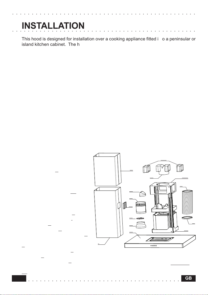
INSTALLATION
○○○○○○○○○○○○○○○○○○○○○○○○○○○○○○○○○○○○○○○○○○○○○○○
This hood is designed for installation over a cooking appliance fitted into a peninsular or
island kitchen cabinet. The hood can be fastened to the ceiling or to a wooden buttress,
using the substantial ceiling fixing system supplied, which is fully adjustable in height.
The hood can be used in either extraction mode (ducted to the outside) or in recirculation
mode (internal recycling).
Safety warnings
• Due to the difficulties which could be experienced when installing this hood, because
of the specific weight of the product, installation should only be carried out by a
qualified or competent technician, in compliance with all the rules concerning the
evacuation of contaminated air. The manufacturer declines all responsibility for any
damage or injury caused as a result of incorrect installation, poor workmanship or
failure to comply with the instructions provided in this manual.
• Do not connect the hood ducting to central heating flues, chimneys, etc..
• The minimum safety distance between the cooker top and the hood is 65 cm.
• Never do flambé cooking under the hood.
• Never leave frying pans unattended during use: overheated fats and oils may ignite.
• If the room in which the hood is to be used contains other non-electric appliances
(such as gas appliances), ensure that there is an adequate supply of air into the room.
When the hood is used in conjunction with other non-electric appliances the negative
pressure in the room must not exceed 0.04 mbar, to prevent fumes from being drawn
back into the room by the hood itself.
Components
The hood is made up of the
following components (fig. 1):
• n.1 hood canopy C, complete with
controls, worktop illumination and
fan unit
• n.1 telescopic frame, comprising:
n.1 upper frame section TS
n.1 lower frame section TI
• n.1 telescopic chimney stack,
comprising:
n.1 upper chimney stack S
n.1 lower chimney stack I
• n.1 deflector D
• n.2 venting grilles G
• n.1 reduction flange Ø 150-120 A
• n.1 additional recirculation spigot
• n.2 recirculation clamps F
• n.1 valve V (optional)
• n.1 recirculation spigot R
• n.2 additional recirculation spigots
12
P
P1
○○○○○○○○○○○○○○○○○○○○○○○○○○○○○○○○○○○○○○○
Fig. 1
GB
Page 5

○○○○○○○○○○○○○○○○○○○○○○○○○○○○○○○○○○○○○○○○○○○○○○○
TS
TI
4324665 01 - 001201
• n. 1 bag with screws for fixing the frame to the ceiling-buttress 1
• n. 1 bag with screws for fixing the chimney stack to the hood canopy 2
• n. 1 bag with screws for fixing the connection box 3
• n. 1 bag containing documents.
Instructions for installation
To facilitate installation, proceed in the order indicated below:
• Installing the Frame.
• Ducting or recirculation fitting.
• Connection to the mains power supply.
• Fitting the telescopic chimney.
• Electrical connection and testing.
• Fitting the hood canopy
Installing the Frame
The frame is suitable for fixing to the ceiling or to a
wooden buttress of suitable thickness, which must
be firmly anchored to the ceiling or to other bearing
structures.
• Using a plumb line or similar tool, identify and mark
the centre on the ceiling or buttress, starting from the
centre of the cooking appliance.
• Use the cardboard template provided to mark the
ceiling or wooden buttress, making sure that the
centres coincide and lining up one of the two axes (A
or B) of the template so that it is parallel with the long
side of the cooking appliance.
• Mark the position of the 4 fixing holes indicated on
the drilling template.
• Drill the holes as follows:
- Ceiling: 4 holes Ø 10 mm to fix the frame in position;
- Buttress: 4 holes Ø 8 mm to fix the frame in position.
Fixing to the Ceiling
Attention: Due to the many differing types of ceiling
construction, the choice of fixings is left to the
discretion of the installer. It is necessary to emphasise
that the fitting has to be absolutely accurate because
of the weight of the cooker hood and because of the
flexing caused by accidental lateral stresses on the
appliance. Only the following types of ceiling are
suitable for installing the Island cooker hood:
• Solid concrete ceiling: use dowels for concrete, not supplied.
• Solid wooden buttress ceiling: use Ø 10 mm wood screws with a minimum length of 120
mm, not supplied.
• Cavity ceiling with inner space, having a wall thickness of about 20 mm; use, in this case
only, the 4 dowels and screws supplied in bag (1). Once fixed, make sure that the base
is absolutely stable, even when the metal frame is subjected to lateral stress. In all other
○○○○○○○○○○○○○○○○○○○○○○○○○○○○○○○○○○○○○○○
13GB
Page 6

○○○○○○○○○○○○○○○○○○○○○○○○○○○○○○○○○○○○○○○○○○○○○○○
cases, if the ceiling is not strong enough in the area where the hood is to be fixed, the
installer must strengthen the area using suitable plates and counterplates anchored to
resistant structures.
Fixing to the Wooden Buttress
• Connect the base of the frame to the beam using the 4 screws size 5.2x70 with nuts and
washers, provided in bag (1)
Fig. 2
8
1
7
2
6
3
5
4
8
1
7
2
6
3
5
8
1
7
2
6
3
5
4
8
1
7
2
6
3
5
4
8
1
7
2
6
3
5
4
4
8
1
7
2
6
3
5
4
8
1
7
2
6
3
5
4
8
1
7
2
6
3
5
4
AB
Ducting or recirculation fitting
• Ducting fitting
• The hood can be connected to the ducting by means of
a rigid or flexible pipe Ø 120 or 150 mm, the choice of
which is left to the installer. When installing with the
pipe Ø 120 mm, it will be necessary to use the reduction
A on the hood outlet.
flange
• To install the hood with the side air outlet from lower
chimney stack I, it is necessary to insert deflector D into
spigot R so as to close off the opening that is not being
used (fig. 3).
• Cut additional recirculation spigot P at a point
corresponding to outlets 1 and 2, indicated directly on
the piece. Connect additional recirculation spigot P to
the round diffuser outlet, pushing it downwards, and fit
spigot R to additional spigot P in a similar manner
(ensure that the two additional recirculation spigots P1
are fitted to spigot R). Make sure that the height of the
assembly R + P corresponds to the height of the chimney
outlet.
• Remove the activated charcoal filters, if fitted (see
paragraph on Maintenance).
14
○○○○○○○○○○○○○○○○○○○○○○○○○○○○○○○○○○○○○○○
R
D
P
P1P1
Fig. 3
GB
Page 7

○○○○○○○○○○○○○○○○○○○○○○○○○○○○○○○○○○○○○○○○○○○○○○○
• Recirculation fitting
• The filtered air is returned to the room through the two plastic venting grilles
G located on
the lower chimney stack I.
• Connect additional recirculation spigot P to the round diffuser outlet, pushing it downwards,
and fit spigot R to additional spigot P in a similar manner (ensure that the two additional
recirculation spigots P1 are fitted to spigot R). Cut additional recirculation spigot P at a
point corresponding to outlets 1 and 2, indicated directly on the additional spigot. Make
sure that the height of the assembly R + P corresponds to the height of the chimney
outlet.
• Fit the activated charcoal filters inside the hood canopy (see paragraph on
Maintenance).Do not fit the venting grilles; this must only be done after installation of the
chimney stack.
Connection to the mains power supply
• Check that the mains voltage corresponds to the one indicated on the rating plate
inside the hood.
• Connect the hood to the mains, inserting a two-pole switch with contact aperture of
at least 3 mm.
• Ensure that the domestic electric system is properly earthed.
• The mains lead should be routed through the central keyhole in the frame before being
connected.
• Connect the mains lead to the power supply.
Fitting the telescopic chimney
• Fit the upper chimney stack S to the frame fastened to the
ceiling or to the wooden buttress.
• Fasten the upper chimney stack using two of the screws
size 2.9x9.5 provided in bag (2), making sure that you insert
one screw on each side of the chimney.
• Fit the lower chimney stack I in a similar way, using two of
the screws size 2.9x9.5 provided in bag (2), inserting the
chimney stack into the same slot used for upper chimney
stack S.
• Fit the two venting grilles, which snap onto the metal, into
the housings provided, so that the symbol
upwards and the symbol
points forwards. For
recirculation versions, also check that the venting grilles
are properly inserted into clamp
R (fig. 4).
points
TS
S
TS
S
I
Fig. 4
○○○○○○○○○○○○○○○○○○○○○○○○○○○○○○○○○○○○○○○
G
TI
15GB
Page 8

○○○○○○○○○○○○○○○○○○○○○○○○○○○○○○○○○○○○○○○○○○○○○○○
Fitting the hood canopy
• Fix the hood canopy C to the telescopic frame
(fig. 5) using 4 screws M6x10 provided in bag
(2).
• Remove the metal grease filters (see paragraph
on Maintenance).
Electrical connection
• Take the two parts of the connection box from
the packing (3).
• Fasten the two connectors together, and insert
them into the connection box. (Fig. 6)
• Close the electrical connection box using 2
screws size 2.9x12.7 provided in bag (3).
• Fasten the electrical connection box to the hood
canopy support using 2 screws size 2.9x6.5
provided in bag (3).
• Replace the metal grease filters (see paragraph
on Maintenance).
• Once the hood has been connected to the
mains, check that the lighting, motor and speed
change are all working correctly.
Fig. 5
Fig. 6
16
○○○○○○○○○○○○○○○○○○○○○○○○○○○○○○○○○○○○○○○
GB
Page 9

○○○○○○○○○○○○○○○○○○○○○○○○○○○○○○○○○○○○○○○○○○○○○○○
V1 V2 V3 L
A18_07
0 - 1 MID MAX 0 - 1
OPERATION
○○○○○○○○○○○○○○○○○○○○○○○○○○○○○○○○○○○○○○○○○○○○○○○
Safety warnings
• Before carring out any kind of maintenance or leaning,disconnect the hood from the
mains supply.
• The grease filters and the charcoal filter should be cleaned or replaced as recommended
by the manufacturer or more frequently if the hood is used consistently over 4 hours
per day.
• When using a gas hob in connection with the cooker hood never leave the burners of
the hob uncovered while the hood is in use or when the pans have been removed.Switch
off the gas before removing the pan,or for just short periods and never leave the hob
unattended.
• Always ensure that the flame is kept at the correct intensity to prevent the flame from
licking round from the bottom of the pan;this will save energy and will avoid a dangerous
concentration of heat.
• Always ensure that the appliance is used in accordance with the manufacturer’s
instructions for the removal of contaminated air and odours during cooking.
Instruction for Use
Control panel
The layout of the control is as follows:
BUTTON L = Turns the lighting system on and off;
BUTTON V1 = Turns the on and off at low speed.This is ideal to obtain a particularly
silent but continuous flow of air when the level of cooking fumes is
low;
BUTTON V2 = Medium speed, suitable for most normal operating conditions.This
gives an excellent ratio between treated air flow and noise level;
BUTTON V3 = High speed,suitable to deal with heavy cooking fumes, even for long
periods of time.
○○○○○○○○○○○○○○○○○○○○○○○○○○○○○○○○○○○○○○○
17GB
Page 10

○○○○○○○○○○○○○○○○○○○○○○○○○○○○○○○○○○○○○○○○○○○○○○○
MAINTENANCE
○○○○○○○○○○○○○○○○○○○○○○○○○○○○○○○○○○○○○○○○○○○○○○○
Regular maintenance and cleaning will ensure good performance and reliability, while
extending the working life of the hood.Special attention should be paid to the grease
filters and to the charcoal filters when the hood is used in the recirculation mode.
Metal grease filters
• Cleaning
The metal grease filter should be cleaned
every two months with normal usage and
can be cleaned in a dishwasher or by hand
using a mild detergent or liquid soap.
• Replacement
Remove the filters one at a time, pushing
the handle towards the rear of the hood
(fig.7). When replacing,ensure that the
handle faces outwards.
ATTENTION - There could be a possible
fire hazard if the filters are not replaced
according to these instructions
Fig. 7
Active carbon filter
• Operation
Active carbon filters can withhold odours up
to saturation.They cannot be washed or
regenerated and must therefore be replaced
every 4 months, or more frequently if
intensely used.
• Replacing
Take off the metal grease filters (fig.7) and
remove the activated charcoal filter from its
housing by turning the clips provided
(fig.8).Fit the new activated charcoal filter and
replace the metal grease filters.
ATTENTION - There could be a possible
fire hazard if the filters are not replaced
according to these instructions
18
○○○○○○○○○○○○○○○○○○○○○○○○○○○○○○○○○○○○○○○
Fig. 8
GB
Page 11

○○○○○○○○○○○○○○○○○○○○○○○○○○○○○○○○○○○○○○○○○○○○○○○
Lighting
Version with halogen spotlights:
90 and 120 cm model, four 20W halogen spotlights.
• To replace (fig.9)
Remove the two screws fixing the metal ring,extract the spotlight from the lamp holder by
pulling gently. When replacing the spotlight, make sure that the two pins are correctly
inserted in the housing on the lamp holder.
Cleaning
When cleaning the hood:
• Never use a wet cloth or sponge, or running water.
• Never use thinners or products containing alcohol, as they might damage the paintwork.
• Never use abrasive cleaning materials, in particular when cleaning stainless steel surfaces.
It is recommended to use a damp cloth and mild liquid household cleaner.
Fig. 9
○○○○○○○○○○○○○○○○○○○○○○○○○○○○○○○○○○○○○○○
19GB
 Loading...