

Page 1

Cappa
Cooker hood
Hotte de cuisine
Dunstabzugshaube
Dampkap
ZHC 930 X
MANUALE DI INSTALLAZIONE, USO E MANUTENZIONE
INSTALLATION, USE AND MAINTENANCE HANDBOOK
MANUEL D’INSTRUCTIONS POUR L’INSTALLATION, L’EMPLOI ET L’ENTRETIEN
HANDBUCH FÜR INSTALLATION, BEDIENUNG UND WARTUNG
INSTRUCTIES VOOR MONTAGE, GEBRUIK EN ONDERHOUD
Page 2

Dear Customer,
If you follow the recommendations
contained in this Instruction Manual, your
appliance will give you constant high
performance and will remain efficient for
many years to come.
CONTENTS
RECOMMENDATIONS AND SUGGESTIONS 14
CHARACTERISTICS 15
INSTALLATION 17
USE 20
MAINTENANCE 21
GB
13
Page 3
RECOMMENDATIONS AND SUGGESTIONS
650 mm min.
INSTALLATION
• The manufacturer will not be held liable for any damages resulting
from incorrect or improper installation.
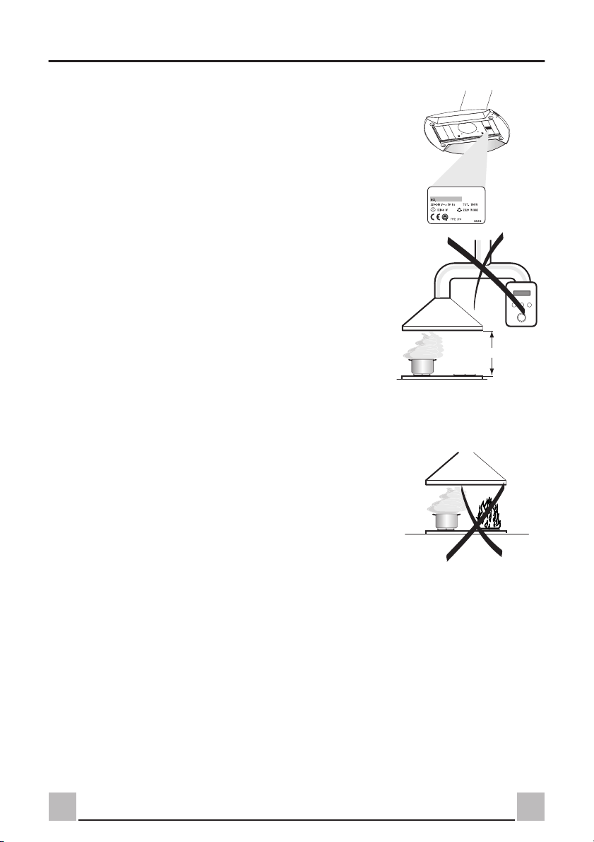
• The minimum safety distance between the cooker top and the
extractor hood is 650 mm.
• Check that the mains voltage corresponds to that indicated on the
rating plate fixed to the inside of the hood.
• For Class I appliances, check that the domestic power supply
guarantees adequate earthing.
• Connect the extractor to the exhaust flue through a pipe of minimum
diameter 120 mm. The route of the flue must be as short as possible.
• Do not connect the extractor hood to exhaust ducts carrying
combustion fumes (boilers, fireplaces, etc.).
• If the extractor is used in conjunction with non-electrical appliances
(e.g. gas burning appliances), a sufficient degree of aeration must be
guaranteed in the room in order to prevent the backflow of exhaust
gas. The kitchen must have an opening communicating directly with
the open air in order to guarantee the entry of clean air.
USE
• The extractor hood has been designed exclusively for domestic use
to eliminate kitchen smells.
• Never use the hood for purposes other than for which it has ben
designed.
• Never leave high naked flames under the hood when it is in
operation.
• Adjust the flame intensity to direct it onto the bottom of the pan only,
making sure that it does not engulf the sides.
• Deep fat fryers must be continuously monitored during use:
overheated oil can burst into flames.
• The hood should not be used by children or persons not instructed in
its correct use.
MAINTENANCE
• Switch off or unplug the appliance from the mains supply before
carrying out any maintenance work.
• Clean and/or replace the Filters after the specified time period.
• Clean the hood using a damp cloth and a neutral liquid detergent.
GB
14
Page 4
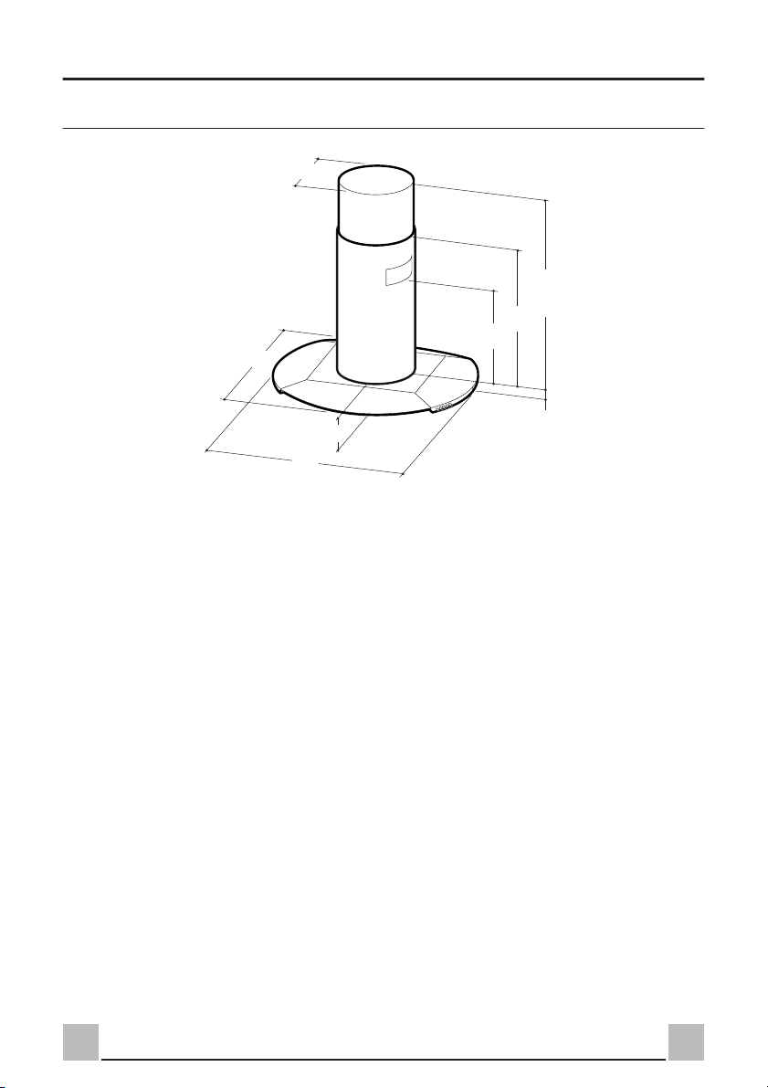
CHARACTERISTICS
732
ø 280
Dimensions
500
890
890 min
1170 max
898
72
55
15
GB
Page 5

21
22
zz
Components
Ref. Q.ty Product Components
1 1 Hood Body, complete with: Controls, Light,
2 1 Telescopic Chimney comprising:
2.1 1 Upper Section
23
14.1
11
12g
12h
14
25
9
2.1
2
2.2
12e
2.2 1 Lower Section
7.1 1 Telescopic frame complete with extractor,
7.1a 1 Upper frame
7.1b 1 Lower frame
15
8 1 Air Outlet Grill
9 1 Reducer Flange ø 150-120 mm
14 1 Hood Body Air Outlet Extension Piece
14.1 1 Air Outlet Connection Extension
15 1 Air Outlet Connection
24 1 Junction box
25 2 Pipe clamps
Ref. Q.ty Installation Components
11 4 Wall Plugs ø 10
12b 3 Screws 2,9 x 4,5
12c 4 Screws 2,9 x 6,5
12e 4 Screws 2,9 x 9,5
12f 4 Screws M6 x 10
12g 4 Screws M6 x 80
12h 4 Screws 5,2 x 70
8
21 1 Drilling template
22 4 6.4 mm int. dia washers
24
23 4 M6 nuts
Blower, Filters
consisting of:
consisting of two Half Shells
GB
Q.ty Documentation
1 Instruction Manual
1
12c
12f
16
Page 6

INSTALLATION
Drilling the Ceiling/shelf and fixing the frame
DRILLING THE CEILING/SHELF
• Use a plumb line to mark the centre of the hob on the ceiling/support shelf.
• Place the drilling template 21 provided on the ceiling/support shelf, making sure that the template is
in the correct position by lining up the axes of the template with those of the hob.
• Mark the centres of the holes in the template.
• Drill the holes at the points marked:
• For concrete ceilings, drill for plugs appropriate to the screw size.
• For hollow brick ceilings with wall thickness of 20 mm: drill ø 10 mm.
• For wooden beam ceilings, drill according to the wood screws used.
• For wooden shelf, drill ø 7 mm.
• For the power supply cable feed, drill ø 10 mm.
• For the air outlet (Ducted Version), drill according to the diameter of the external air exhaust
duct connection.
FIXING THE FRAME
Before fixing, separate the two sections of the frame
by unscrewing the 6 side screws to obtain the Upper
frame and Lower frame.
17
GB
Page 7

Upper frame
• Align the power supply cable feed hole
• Fix the upper frame to the ceiling or shelf using:
• For concrete ceilings, use the appropriate plugs for the screw size (not provided).
• For hollow brick ceilings of wall thickness of approximately 20 mm: use 4 plugs 11 and 4
screws 12h, provided.
• For wooden beam ceilings, use 4 wood screws (not provided).
• For wooden shelf, use 4 screws 12g with washers 22 and nuts 23, provided.
Lower frame
• Fix the lower frame using the 8 previously removed screws, adjusting the length according to the
installation height (hood body lower fixing surface must be at least 720 mm from the hob).
• For the recirculation version, turn the frame in the direction chosen for the recirculated air outlet.
• The frame mountings must be secure to withstand the weight of the hood and any stresses caused by
the occasional side thrust applied to the device. On completion, check that the base is stable, even if
the frame is subjected to bending.
• In all cases where the ceiling is not strong enough at the suspension point, the installer must provide
strengthening using suitable plates and backing pieces anchored to the structurally sound parts.
Connections
DUCTED VERSION AIR EXHAUST SYSTEM
When installing the ducted version, connect the hood to the chimney using either a flexible or rigid
pipe ø 150 or 120 mm, the choice of which is left to the installer..
• To install a ø 120 mm air exhaust connection,
insert the reducer flange 9 on the hood body
outlet.
• Fix the pipe using the pipe clamps 25 provided.
• Remove any activated charcoal filters.
9
RECIRCULATION VERSION AIR OUTLET
• Insert reducer flange 9 on the extractor outlet.
• Push fit the extension piece 14 onto the flange.
• Push fit connector 15 onto the extension piece.
• Insert extension piece/connector 14.1 laterally on
connector 15, ensuring that the outlet is in line with
the chimney intake.
GB
ø 120ø 150
15
14.1
14
9
18
Page 8

Flue assembly - Mounting the hood body
• Position the upper chimney section and fix the
upper part to the frame using the 2 screws 12c
provided.
• Similarly, position the lower chimney section
without fixing it, ensuring that the outlet from
connector 15 is in line with the chimney intake.
• The air outlet directional grill 8 must be fitted
after the installation of the chimney.
Before fixing the hood body to the frame:
• remove the grease filters from the hood body;
• remove the activated carbon odour filters, if
fitted.
• from below, use the 4 screws 12f provided to fix
the hood body to the frame.
8b
• For the recirculation version, locate the
directional grill 8 in its housing. Ensure that it is
inserted correctly in connector 15.
ELECTRICAL CONNECTION
• Connect the hood to the mains through a twopole switch having a contact gap of at least 3 mm.
• Connect the control connector Cmd.
• Place the connector in the junction box 24 and
close it using the 4 screws 12e provided.
• Fix the junction box to the hood body using the 2
screws 12c provided.
• For the recirculation version, fit the activated
carbon odour filter.
• Replace the grease filters.
12f
24
12e
Cmd
12c
19
GB
Page 9

USE
Control panel
LM V3S1 S2V2V1
L Light Switches the lighting system on and off.
S1 Led Motor running led. Flashes when the grease filters are saturated.
S2 Led Intensive speed led. Flashes when the activated carbon odour filters are exhausted.
M Motor Switches the extractor motor on and off at low speed. Used to provide a contin-
uos and silent air change in the presence of light cooking vapours.
V1 Speed Reduces the operating speed
V2 Speed Increases the operating speed
V3 Intensive
speed
Maximum speed, used for eliminating the highest cooking vapour emission.
Switches off automatically after 10 minutes operation. Can also be switched off
manually by pressing the button
GB
20
Page 10

MAINTENANCE
Grease filters
CLEANING METAL SELF-SUPPORTING GREASE FILTERS
Alarm signal reset
• Switch of the lights and extractor motor.
• Press button V3 for at least 3 seconds, until the
leds start to flash.
Cleaning the filters
• The filters are washable and must be cleaned when
led S1 flashes or at least every 2 months of
operation, or more frequently for particularly
heavy usage.
• Remove the filters one at a time by pushing them
towards the back of the group and pulling down
at the same time.
• Wash the filters, taking care not to bend them.
Allow them to dry before refitting.
• When refitting the filters, make sure that the
handle is visible on the outside.
21
GB
Page 11

Activated charcoal filter (Recirculation version)
REPLACING THE ACTIVATED CHARCOAL FILTER
• The filter is not washable and cannot be
regenerated. It must be replaced when led S2
flashes or at least every 4 months. The alarm
signal will only light up when the extractor motor
is switched on.
Alarm signal reset
• Switch off the lights and extractor motor.
• Press button V3 for at least 3 seconds, until the
leds start to flash.
Replacing the Filter
• Remove the metal grease filters
• Remove the saturated activated carbon filter by
releasing the fixing hooks
• Fit the new filter by hooking it into its seating
• Replace the metal grease filters.
Alarm signal activation
• On the recirulcation version extractor hood, the
filter saturation alarm is activated during
installation or at a later date.
• Switch off the lights and extractor motor.
• Press button V3 for at least 10 seconds, until the
leds start to flash:
• 2 flashes of the activated carbon odour filter
saturation alarm led = filter ACTIVATED
• 1 flash of the activated carbon odour filter
saturation alarm led = filter DEACTIVATED
Lighting
LIGHT REPLACEMENT
• 20 W halogen light.
• Remove the 2 screws fixing the ring nut.
• Extract the lamp from the lamp holder by pulling
gently.
• Replace with another of the same type, making
sure that the two pins are properly inserted in the
lamp holder socket holes.
• Replace the ring nut and fix it in place using the
two screws removed as above.
GB
22
Page 12

Page 13

Quest’apparecchio é conforme alla norma europea sulla bassa tensione C.E.E. 73/23 relativa
alla sicurezza elettrica e alle norme europee: C.E.E. 89/336 relativa alla compatibilità elettromagnetica e C.E.E. 93/68 relativa alla marcatura CE.
This appliance complies with European regulations on low voltages, EEC Directive 73/23 on
electrical safety, and with the following European regulations: EEC Directive 89/336 on
electromagnetic compatibility and EEC Directive 93/68 on EC marking.
Cet équipement est conforme à la norme européenne sur la basse tension C.E.E. 73/23 relative à la sécurité électrique et aux normes européennes: C.E.E. 89/336 relative à la compatibilité
électromagnétique et C.E.E. 93/68 relative au marquage CE.
Dieses Gerät entspricht den europäischen Niederspannungsrichtlinien 73/23/EWG zur
elektrischen Sicherheit, den europäischen Richtlinien 89/336/EWG zur elektromagnetischen
Verträglichkeit und den Richtlinien 93/68/EWG zur CE-Kennzeichnung
Dit apparaat voldoet aan de Europese Laagspanningsrichtlijn 72/23/EEG inzake de elektrische
veiligheid en aan de Europese normen 89/336/EEG inzake de elektromagnetische compatibiliteit
en 93/68/EEG inzake de CE-markering.
436000235 01 - 011214
 Loading...