

Page 1

GAS HOB
ГАЗОВАЯ
ВАРОЧНАЯ
ПОВЕРХНОСТЬ
ZGL 646
ZXL 636
INSTRUCTION BOOKLET
РУКОВОДСТВО ПО ЭКСПЛУАТАЦИИ
RU
Page 2

English
Important Safety Information
These warnings are provided in the interest of safety. You MUST read them carefully before
installing or using the appliance.
About Installation, Cleaning
and Manteinance
• It is mandatory that all operations required for the
installation are carried out by a qualified or competent
person, in accordance with existing rules and
regulations.
• Disconnect the appliance from the electrical supply,
before carrying out any cleaning or manteinance work.
• Ensure a good ventilation around the appliance. A
poor air supply could cause lack of oxygen.
• Ensure that the gas supply complies with the gas type
stated on the identification label, placed near the gas
supply pipe.
• Using a gas cooking appliance will produce heat
and moisture in the room which it has been
installed in. Ensure a continuous air supply,
keeping the air vents in good conditions or
installing a cooker hood with discharge tube.
• In case of intensive or long time use of the
appliance, make the ventilation more efficient,
by opening a window or increasing the electric
exhaust fan power.
• Once you removed all packaging from the appliance,
ensure that it is not damaged and the electric cable is
in perfect conditions. Otherwise, contact your dealer
before proceeding with the installation.
• The manufacturer disclaims any responsability
should all the safety measures not be carried out.
• Under no circumstances should you attempt to repair
the appliance yourself. Repairs carried out by
unexperienced persons may cause injury or serious
malfunctioning. Refer to your local Service Centre.
Always insist on genuine spare parts.
unexperienced persons may cause injury or serious
malfunctioning. Refer to your local Service Centre.
Always insist on genuine spare parts.
• Ensure that all control knobs are in the OFF position
when not in use.
• Should you connect any electrical tool to a plug near
this cooking appliance, ensure that electric cables are
not in contact with it and keep them far enough from
the heated parts of this appliance.
• If the appliance is out of order, disconnect it from the
electric supply.
Child Safety
• This appliance has been designed to be operated by
adults and children under supervision. Young children
MUST NOT be allowed to tamper with the controls or play
near or with the appliance.
• Accessible parts of this appliance may become hot
when it is in use. Children should be
has cooled.
•
This appliance is not intended for use by children or
other persons whose physical, sensory or mental
capabilities or lack of experience and knowledge
prevents them from using the appliance safely without
supervision or instruction by a responsible person to
ensure that they can use the appliance safely.
KEPT AWAY until it
Environmental Information
• After installation, please dispose of the packaging with
due regard to safety and the environment.
• When disposing of an old appliance, make it unusable,
by cutting off the cable.
During Operation
• It is most important that this instruction book should
be retained with the appliance for future reference.
Should the appliance be sold or transferred, always
ensure that the book is left with the appliance in order
that the new owner can get to know the functions of the
appliance and the relevant warnings.
• This appliance has been designed for non professional
purpose in private houses only. It is meant to cook
edible foodstuff only and
purposes.
• It is dangerous to alter the specification in any way.
• For hygiene and safety reasons, this appliance should
be kept clean at all times. A build-up of fats or other
foodstuff could result in a fire.
• Under no circumstances should you attempt to repair
the appliance yourself. Repairs carried out by
2
MUST NOT be used for any other
• The symbol
indicates that this product may not be treated as
household waste. Instead it shall be handed over to
the applicable collection point for the recycling of
electrical and electronic equipment. By ensuring this
product is disposed of correctly, you will help prevent
potential negative consequences for the environment
and human health, which could otherwise be caused
by inappropriate waste handling of this product. For
more detailed information about recycling of this
product, please contact your local city office, your
household waste disposal service or the shop where
you purchased the product.
These instructions are only for the countries
stated by the symbol printed on the front cover
of this instruction book.
on the product or on its packaging
Page 3

Contents
For the User
Important Safety Information 2
Instruction for the User 3
Cleaning and Maintenance 5
This appliance complies with the following
E.E.C. Directives:
- 2006/95 (Low Voltage Directive);
- 89/336
- 93/68 (General Directives)
and subsequent modifications.
MANUFACTURER:
ELECTROLUX HOME PRODUCTS ITALY S.p.A.
Viale Bologna, 298
47100 FORLÌ (Italy)
(Electromagnetical Compatibility Directive);
For the Installer
Technical Data 6
Instruction for the Installer 6
Electrical Connection 7
Adaptation to different types of gas 8
Building In 9
Possibilities for insertion 10
Guide to Use the instructions
The following symbols will be found in the text to guide
you throughout the Instructions:
Safety Instructions
!!
!
!!
Step by step instructions for an operation
Hints and Tips
Environmental information
Instruction for the User
Once the hob has been installed, it is
important to remove any protective materials,
which were put on in the factory.
Hob burners control knobs
The hob burners control knobs are situated on the hob
right hand side. The symbols on the knobs mean that:
there is no gas supply
•
there is maximum gas supply
there is minimum gas supply
A - Burner cap
Lighting the burners
For easier lighting, proceed before putting a
pan on the pan support.
B - Burner crown
C - Ignition candle
D - Thermocouple
Fig. 1
!!
!
!!
Models with semi-automatic ignition
To light a burner, depress the relevant switch
marked with a small spark. Then, push in the
relevant knob and turn it anticlockwise to "maximum
position" (ZGL 646 I).
Fig. 2
3
Page 4
!!
!
!!
Push in the relevant knob and turn it anticlockwise
to "maximum position". After lighting the flame,
keep the knob pushed down for about 5 seconds.
This will allow the "thermocouple" (Fig. 2, lett. D)
to be heated and the safety device to be switched
off, otherwise the gas supply would be interrupted
(ZGL 646 IT - ZXL 636) .
Then, check the flame is regular and adjust it as
required.
If you cannot light the flame even after several
attempts, check the "cap" (Fig. 1-2, lett. A) is in
the correct position.
To put the flame out, turn the knob to the symbol !.
• Always turn the flame down or put it out before
taking the pans off the burner..
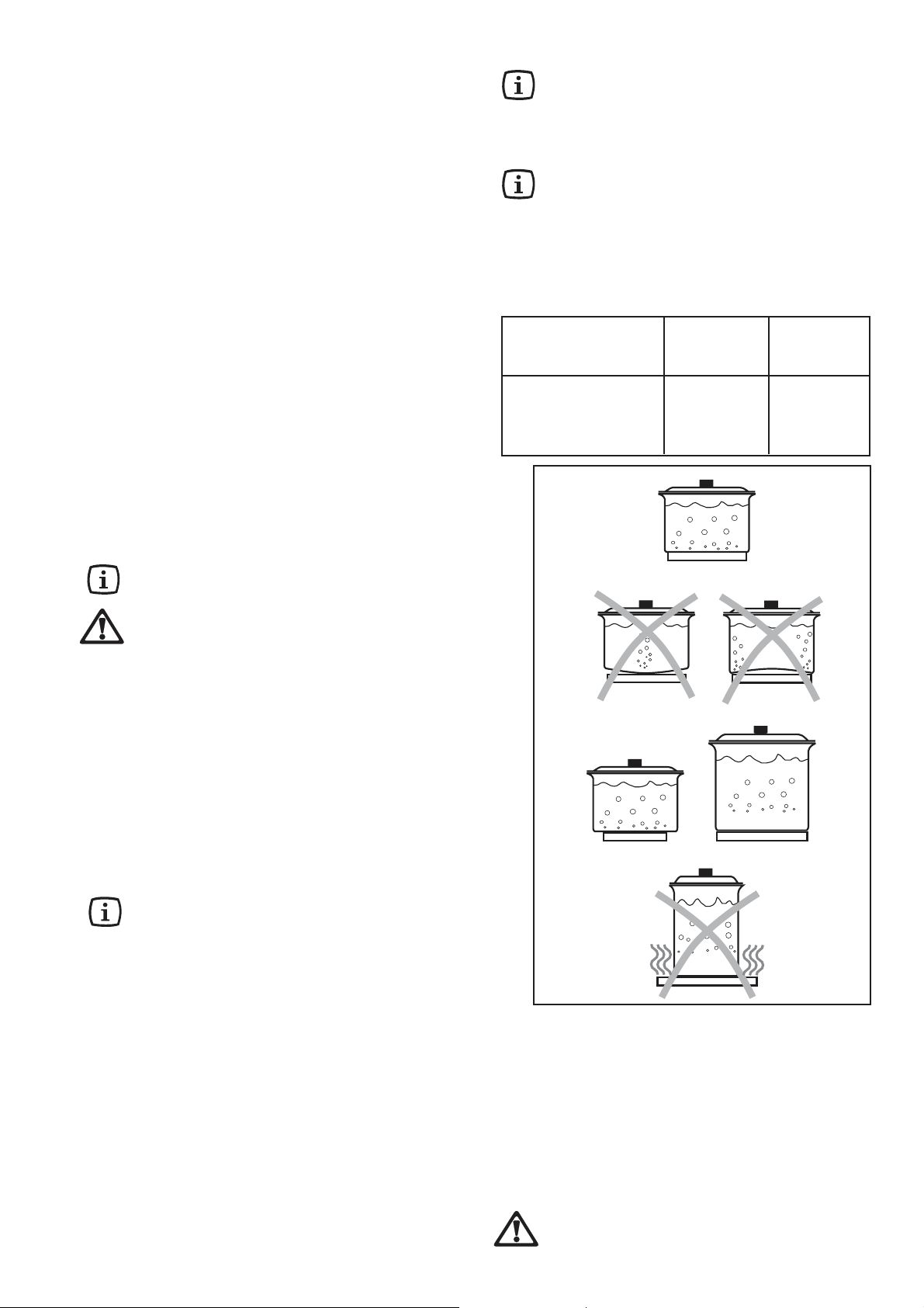
Using the hob correctly
To ensure maximum burner efficiency, it is strongly
recommended that you use only pots and pans with a
bottom fitting the size of the burner used, so that flame will
not spread beyond the bottom of the vessel.
It is also advisable, as soon as a liquid starts boiling, to
turn down the flame so that it will barely keep the liquid
simmering.
Models with automatic ignition
In the absence of electricity, ignition can occur
without the electrical device; in this case approach
the burner with a flame, push the relevant knob
down and turn it anti-clockwise until it reaches
the"maximum" position.
When switching on the mains, after installation or
a power cut, it is quite normal for the spark
generator to be activated automatically.
Burner minimum maximum
diameter diameter
Big (rapid) 160 mm. 260 mm.
Medium (semirapid) 120 mm. 220 mm.
Small (auxiliary) 80 mm. 160 mm.
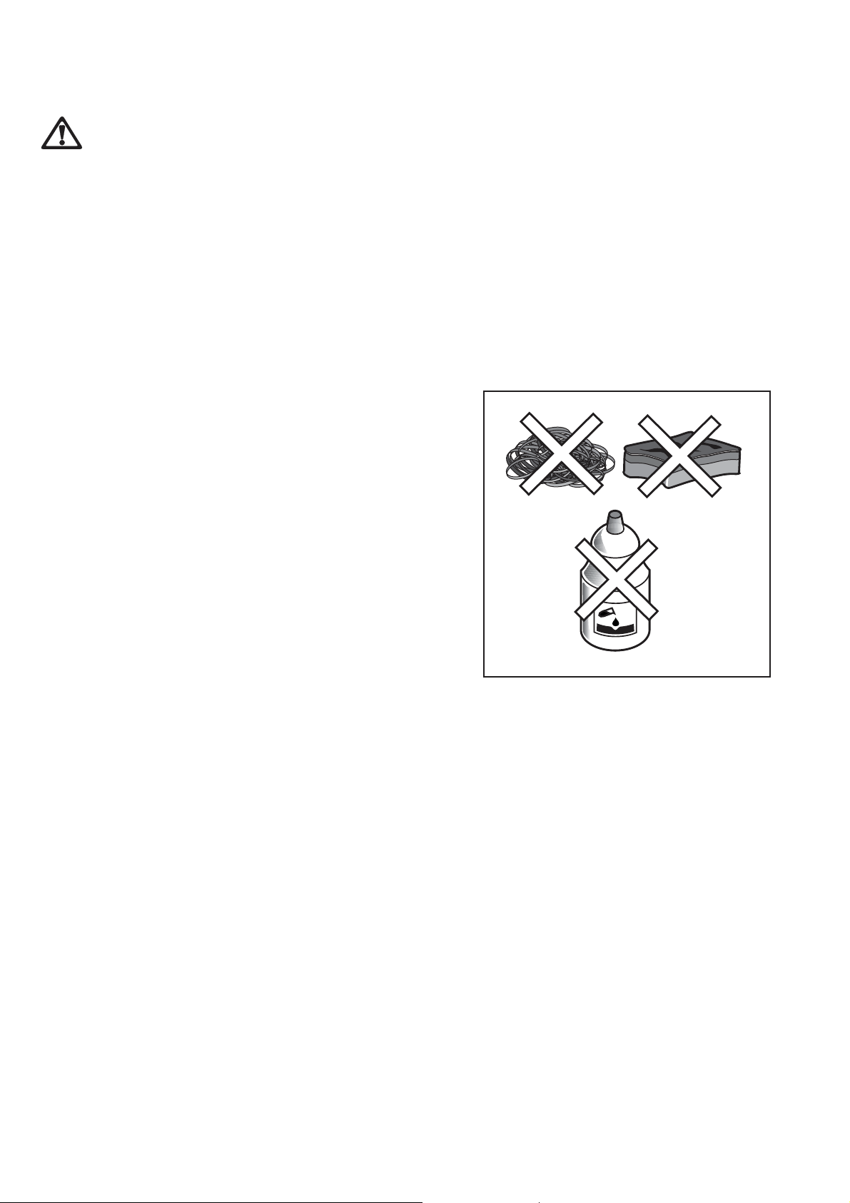
Use only pans or pots with flat bottom.
Carefully supervise cookings with fats or
oil, since these types of foodstuff can result
in a fire, if over-heated.
Use of electric plate (ZXL 636)
To switch on the plates, turn the relevant knob to the
required position.
The plates are regulated by a 7 position switch:
Position 0: off
Position 1: minimum disbursement of heat
Position 6: maximum disbursement of heat
The pilot light signals the connection of the electric plate.
It is important to note that the plate may smoke a
little and produce a slightly unpleasant odour when
used for the first time. This is quite normal and
will disappear after a few minutes.
Using the plate correctly
• When cooking by electric, saucepans should have a
thick base and be perfectly flat in order to ensure
total contact with the plate and, consequently, perfect
conduction.
• Occasionally, saucepans have a thin bottom and these
loose their shape over a period of time. In this manner
two of the qualities of the electric plate are lost: the
even distribution of heat and the saving of energy.
Cooking time is also lengthier.
• As regards the size of the saucepans: for best
results, the plate and the saucepan should have the
same diameter. The diameter of the saucepan may
be slightly larger; a smaller diameter is not advised.
• Never leave the plates on without a saucepan! Switch
off the plate just before the end of cooking time. The
heat accumulated by the plate will finish cooking the
food and save energy.
When cooking with fats or oils maximum care
must be taken as these can self-ignite when
4
over-heated.
Page 5
Cleaning and Maintenance
Disconnect the appliance from the electrical
supply, before carrying out any cleaning or
manteinance work.
General cleaning
Wash the enamelled components with warm soapy
water. Never use abrasive cleaners.
Frequently wash the "caps" and the "crowns" with hot
soapy water, carefully taking away any built-up of food.
Regularly wipe over the hob top using a soft cloth weel
wrung out in warm water to which a little liquid detergent
has been added. Avoid the use of the following:
- household detergent and bleaches;
- impregnated pads unsuitable for non-stick saucepans;
- steel wool pads;
- bath/sink stain removers.
Should the hob top become heavily soiled, it is
recommended that a proper cleaning product is used.
Pan supports
The pan supports are dishwasher proof.
If the marks are particularly difficult to remove, use
common non-abrasive cleaners or specific products.
Never use steel wool pads or acids.
Ignition candle
The electric ignition is obtained through a ceramic
"candle" and a metal electrode (Fig.1-2 lett. C). Keep
these components well clean, to avoid difficult lighting,
and check that the burner crown holes are not
obstructed.
Cleaning of the hotplates
Spills on the hotplates should be removed using warm
water and a soft cloth.
Alternatively, wipe the plates with a drop of olive oil on a
kitchen towel (while the plates are still warm).
Periodic Maintenance
Periodically ask your local Service Centre to check the
conditions of the gas supply pipe and the pressure
adjuster, if fitted.
To ensure the good operation of the hob and its safety
features, it is necessary that the taps are periodically
lubricated.
Fig. 3
FO 2110
5
Page 6
Technical Data
Gas Burners Rating
Rapid Burner 3,0 kW (G20) - 2,8 kW (G30/G31)
Semirapid Burner 2,0 kW
Auxiliary Burner 1,0 kW
Appliance Class 3
Category II2H3B/P
Electric hotplate (ZXL 636)
Ø 145 mm. 1,5 kW
Electric Supply
230 V ~ 50 Hz
Setting
Hob recess dimensions
Natural gas G20 - 20 mbar
Gas connection G 1/2"
Length 550 mm.
Width 470 mm.
Instruction for the Installer
• The following instructions about installation and
maintenance must be carried out by qualified
personnel in compliance with the regulation in
force.
• The side walls of the unit in which the hob is
going to be installed, must not exceed the height
of the working top.
• Avoid installing the appliance in the proximity of
inflammable materials (e.g. curtains, tea towels
etc.).
• The appliance must be electrically disconnected
before all interventions. If any electric supply to
the appliance is required to carry out the work,
ensure all the necessary precautions are followed.
THE MANUFACTURER WILL NOT ACCEPT
LIABILITY, SHOULD ANY OF THE OTHER SAFETY
INSTRUCTIONS INCORPORATED IN THIS BOOK
OR THE REGULATION IN FORCE BE IGNORED.
Gas connection
Choose fixed connections or use a flexible pipe in
stainless steel in compliance with the regulation in force.
If using flexible metallic pipes, be careful they do not
come in contact with mobile parts or they are not
squeezed. Use the same attention when the hob is
combinated with an oven.
IMPORTANT - To ensure a correct operation, a saving
of energy and the long-life of the appliance, the voltage
pressure of the appliance must correspond to the
recommended values.
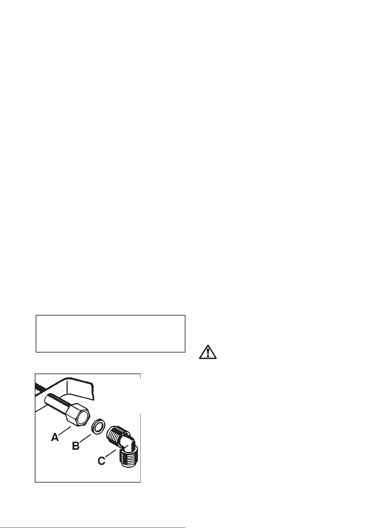
The adjustable connection is fixed to the comprehensive
ramp by means of a threaded nut G 1/2". Interpose the
sealing between the components as shown in Fig. 4.
Screw the parts without forcing, adjust the connection in
the required direction and tighten everything.
IMPORTANT - When the final connection has
been made, it is essential that a thorough leak
test is carried out on the hob and installation.
Use some soapy water, never a flame.
FO 0264
6
A) Ramp with ending nut
B) Seal
C) Adjustable connection
Fig. 4
Page 7
Electrical Connection
The appliance is designed to be connected to 230 V
monophase electricity supply.
The connection must be carried out in compliance with
the laws and regulations in force.
Before the appliance is connected:
1) check that the main fuse and the domestic installation
can support the load (see the rating label);
2) check that the power supply is properly earthed in
compliance with the current rules;
3) check the socket or the double pole switch used for
the electrical connection can be easily reached with
the appliance built in the forniture unit.
The appliance is supplied with a connection cable. This
has to be provided with a proper plug, able to support the
load marked on the identification plate. The plug has to
be fitted in a proper socket.
If connecting the appliance directly to the electric system,
it is necessary that you install a double pole switch
between the appliance and the electricity supply, with a
minimum gap of 3 mm. between the switch contacts and
of a type suitable for the required load in compliance with
the current rules.
The connection cable has to be placed in order that, in
each part, it cannot reach a temperature 90 °C higher than
the room temperature.
The brown coloured phase cable (fitted in the terminal
block contact marked with "L") must always be connected
to the network phase.
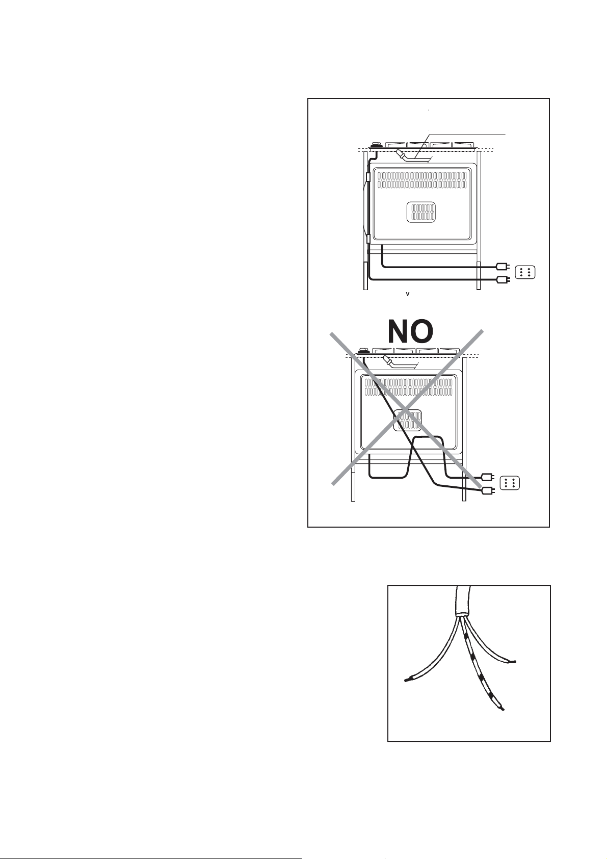
YES
RIGID COPPER PIPE OR
FLEXIBLE PIPE IN STAINLESS
STEEL
Replacement of the voltage cable
Only cable types H05RR-F, H05V2V2-F T90 or H05 BB-F
must be used. The cable section must be suitable to the
voltage and the working temperature.
The yellow/green earth wire must be approximately 2 cm.
longer than the phase wires (Fig. 6).
FO 0238
Fig. 5
Neutral
Earth (yellow/green)
FO 0073
Fig. 6
7
Page 8

Adaptation to different types of gas
Injectors replacement
• Remove the pan supports.
• Remove the burner's caps and crowns.
• With a socket spanner 7 unscrew and remove the
injectors (Fig. 7), and replace them with the ones
required for the type of gas in use (see table 2).
• Reassemble the parts, following the same procedure backwards.
• Replace the rating label (placed near the gas supply
pipe) with the relevant one for the new type of gas
supply. You can find this label in the package of the
injectors supplied with the appliance.
Should the feeding gas pressure be different or variable
compared with the required pressure, an appropriate
pressure adjuster must be fitted on the gas supply pipe,
in compliance with the rules in force.
Adjustment of minimum level
Fig. 7
FO 0392
To adjust the minimum level of the burners, proceed as
follows:
Fig. 8
• Light the burner.
• Turn the knob on the minimum position.
• Remove the knob.
By-pass screws
• With a thin screwdriver, adjust the by-pass screw
(see Fig. 8). If changing from natural gas to LPG,
completely tighten clockwise the screw, until a
small regular flame is obtained. If changing from
LPG to natural gas unscrew about 1/4 turn the bypass screw, until a small regular flame is obtained.
• Finally check the flame does not go out when
quickly turning the knob from the maximum position
to the minimum position.
This procedure can easily be carried out, anyhow the hob
has been positioned or built in the working top.
Table 1 : By-pass diameters
Burner Ø By-pass
in 1/100
of mm.
Auxiliary 28
Semi-rapid 32
Rapid 42
Table 2 : injectors
TYPE TYPE OF INJECTORS NOMINAL REDUCED NOMINAL NOMINAL
OF GAS BURNER MARKS POWER POWER POWER PRESSURE
1/100 mm INPUT k W mbar
KW m3/h g/h
NATURAL
GAS
G 20
LPG
(Buthane/
Propane)
8
Rapid (large) 119 3,0 0,75 0,286 -
Semi-rapid (medium) 96 2,0 0,45 0,190 - 20
Auxiliary (small) 70 1,0 0,33 0,095 -
Rapid (large) 86 2,8 0,75 - 204
Semi-rapid (medium) 71 2,0 0,45 - 145 30/30
Auxiliary (small) 50 1,0 0,33 - 73
Page 9

Building In
SR
R
PE
SR
R
SR
A
580
500
Mod. ZGL 646
These hobs can be inserted in a built-in kitchen unit
whose depth is between 550 and 600 mm. The hobs
dimensions are shown in the relevant diagram.
The edge of the cut out must have a minimum distance
from the rear wall of 55 mm.
If there are side walls, or sides of the furniture unit near
the hob, the cut out edges must have a minimum
distance of 100 mm.
Hanging forniture units or hoods must be placed at 650
mm. minimum from the hob.
A
580
500
Mod. ZXL 636
Dimensions are given in millimeters
A = Auxiliary burner
SR = Semirapid burner
R = Rapid Burner
PE = Electric hotplate
Fitting the hob to the worktop
The hobs can be installed in a kitchen unit with an
opening for insertion whose dimensions are shown in
Fig. 9. To install the hob, proceed as follows:
1) Place the sealing gasket (supplied with the hob) on
the edges of the cut out: place it exactly on the front
and rear edge, taking care that the sealings meet
without overlapping;
2) Fix the hob with the relevant screws (Fig. 10). The
traction of the screws is able to trace the sealing, any
excess of which can be easily removed.
The edge of the hob forms a double labyrinth seal which
provides a total guarantee against infiltration of liquids.
Fig. 9
Fig. 10
FO 2098
a
FO 0199
a) Sealing gasket
9
Page 10

Possibilities for insertion
Kitchen unit with door
Proper arrangements must be taken in designing the
forniture unit, in order to avoid any contact with the
bottom of the hob which can be heated when it is
operated. The recommended solution is shown in Fig.
11.
The panel fitted under the hob should be easily
removable to allow an easy access if a technical
assistance intervention is needed.
Fig. 11 Fig. 12
Kitchen unit with oven
The hob recess dimensions must comply the indication
given in Figs. 12 and 13 and must be provided with
brackets to allow a continuous supply of air.
To avoid overhating, the building in should be carried out
as shown in Figs. 14 e 15.
The hob's electric connection and the oven's one must
be carried out separately, both for safety reasons and
to allow the oven to be easily taken off the unit.
In case a hood with lenght of 600 mm. is fitted over the
hob, the hanging furniture units beside the hood must
be placed at 650 mm. minimum from the hob (Fig.16).
Fig. 13
595
FO 1013
a) Removable panel
b) Space possibly useful for
connections
Fig. 14
FO 0939 FO 0938
Fig. 15
FO 0947
FO 0198
Fig. 16
FO 2099
10
Page 11

Service and original spare parts
This machine, before leaving the factory, has been tested and studied by many experts and specialists, in order to give
you the best results.
Any repair work which needs to be carried out should be done with the utmost care and
attention.
For this reason we reccomend that for any problem you contact the dealer who sold it to you,
or our nearest authorized Service Centre, specifying the nature of the problem and the particular
model which you own. Always Insist on genuine original spare parts.
11
Page 12

РУССКИЙ
Важная информация по безопасности
Эти рекомендации приведены в интересах вашей безопасности. Обязательно внимательно прочитайте эти
рекомендации перед установкой и использованием прибора.
При эксплуатации
• Данный прибор предназначен для приготовления
пищи в быту и только для личного хозяйства.
Прибор не следует использовать для других
целей.
• Опасно вносить любые изменения в конструкцию
прибора.
• По соображениям гигиены и безопасности
варочную поверхность следует содержать в
чистоте. Отложения жира или другие остатки
пищи могут привести к воспламенению.
• Ни при каких обстоятельствах не пытайтесь
отремонтировать прибор самостоятельно.
Ремонт, выполненный неквалифицированным
персоналом, может привести травмам и
серьезным повреждениям прибора. Обратитесь
в ближайший авторизованный изготовителем
сервисный центр. При ремонте должны
использоваться оригинальные запасные части.
• Если прибором не пользуются, все регуляторы
должны находиться в выключенном положении.
• При подключении к электросети любых
электрических приборов вблизи варочной
поверхности, следите за тем, чтобы
электрический кабель не находился слишком
близко к нагревающимся частям прибора.
• При обнаружении неисправности в приборе,
отключите его от сети.
Безопасность детей
• Прибор предназначен для использования
взрослыми, дети могут пользоваться прибором
только под присмотром. Не разрешайте
маленьким детям дотрагиваться до регуляторов
прибора и играть с ним или вблизи него.
• При использовании прибора некоторые его части
могут сильно нагреваться. Держите детей вдали
от прибора, пока он не остынет.
При установке, уходе и очистке
• Все работы по установке прибора должны
проводиться квалифицированным специалистом
в соответствии с действующими правилами и
нормами.
• Перед выполнением любых работ по уходу и
очистке обязательно отлючите прибор от
электросети.
• Вокруг прибора должна быть обеспечена
надлежащая вентиляция. Плохое снабжение
свежим воздухом приведет к недостатку
кислорода.
• Убедитесь в том, что тип и давление газа в месте
подключения соответствуют характеристикам,
указанным на табличке с техническими данными
прибора, расположенной рядом с отводом трубы
для подключения газа.
12
• При использовании газовых приборов
выделяется тепло и влага. Следите за тем,
чтобы к прибору был обеспечен постоянный
приток свежего воздуха. Для этого следите
за чистотой вентиляционных отверстий
помещения или установите надплитный
вытяжной вентилятор.
• В случае длительного или интенсивного
использования прибора обеспечьте более
эффективную вентиляцию, открыв окно или
переключив надплитный вентилятор в более
интенсивный режим.
• После полной распаковки прибора убедитесь в
том, что прибор не поврежден и что кабель
питания в хорошем состоянии. В случае
обнаружения повреждений немедленно
обратитесь к поставщику.
• При невыполнении указанных мер
безопасности изготовитель снимает с себя
всю ответственность.
Обслуживание
• Ни в коем случае не пытайтесь отремонтировать
прибор сами. Ремонт, выполненный
неквалифицированным персоналом, может
привести к травмам и серьезным неисправностям
прибора. Обращайтесь в ближайший
авторизованный изготовителем сервисный центр
(см. отдельный список сервисных центров). При
ремонте должны использоваться оригинальные
запасные части.
Защита окружающей среды
• После установки прибора, пожалуйста,
утилизируйте упаковку в соответствии с
действующими правилами по безопасности и
защите окружающей среды.
• При утилизации старого прибора выведите его из
строя, отрезав кабель питания.
• Символ на самом изделии или его упаковке
указывает, что при утилизации данного изделия
с ним нельзя обращаться как с обычными
бытовыми отходами. Вместо этого, его следует
сдавать в соответствующий пункт приемки
электрического и электронного оборудования
для последующей утилизации. Обеспечив
правильную утилизацию данного изделия, Вы
поможете предотвратить потенциальные
негативные последствия для окружающей среды
и здоровья человека, которые могли бы иметь
место в противном случае. За более подробной
информацией о правилах обращения с такими
изделиями, их утилизации и переработки
обращайтесь в местные органы власти, в службу
по утилизации отходов или в магазин, в котором
Вы приобрели данное изделие.
Page 13

Содержание
Важная информация по
безопасности 12
Инструкции для пользователя 13
Регуляторы управления конфорками 13
Зажигание конфорок 14
Правильная эксплуатация прибора 14
Электрическая зона нагрева (ZXL 636) 15
Уход и очистка 15
Технические данные 16
Инструкции по установке 16
Электрическое подключение 17
Регулировка для различных
типов газа 18
Установка в кухонной мебели 20
Варианты встраивания 21
Сервис и запчасти 22
Гарантия/сервисная служба 22
ЕВРОПЕЙСКАЯ ГАРАНТИЯ 22
Данный прибор соответствует следующим
директивам и их последующим изменениям
ЕЭС:
2006/95 (Директива по низкому напряжению)
89-336 (Директива по электромагнитной совместимости)
93/68 (Общие директивы)
90/396 (Директива для газовых приборов)и
их последующим поправкам.
ПРОИЗВОДИТЕЛЬ:
ELECTROLUX HOME PRODUCTS ITALY S.p.A.
Viale Bologna 298 – 47100 FORLI’ (Италия)
Символы, использующиеся в инструкции
Следующие символы помогут вам ориентироваться
в тексте инструкции:
Рекомендации по безопасности
Пошаговые рекомендации при
использовании прибора
!!
!
!!
Советы и рекомендации
Информация по защите окружающей среды
Важно чтобы данная инструкция по
эксплуатации всегда хранилась вместе с
прибором и ее можно было использовать для
справок. Если вы продаете прибор, передаете его
другому лицу или оставляете на старом месте
при переезде, не забудьте передать эту
инструкцию новым пользователям, чтобы они
могли ознакомиться с работой прибора и
правилами по технике безопасности.
Инструкции для пользователя
Регуляторы управления
конфорками
Регуляторы управления конфорками расположены в
правой части варочной поверхности. Символы на
регуляторах означают следующее:
подача газа отключена
•
максимальная подача газа
минимальная подача газа
13
Page 14

Зажигание конфорок
Конфорка зажигается легче, если на нее еще
не установлена посуда.
!!
!
!!
!!
!
!!
Модели с полуавтоматическим зажиганием
(ZGL 646 I) (Рис. 1)
Чтобы зажечь конфорку, нажмите на
соответствующую кнопку, обозначенную
символом маленькой искры. Затем нажмите
соответствующий регулятор конфорки и
поверните его по часовой стрелке в положение
максимальной подачи газа.
Модели с автоматическим зажиганием
(ZGL 646 IT - ZXL 636)
Нажмите соответствующий регулятор
конфорки и поверните его по часовой стрелке
в положение максимальной подачи газа.
При наличии защитного устройства
(термопары) (рис. 2-D) После зажигания
пламени подержите регулятор нажатым еще
примерно 5 секунд, чтобы защитное
устройство прогрелось, иначе пламя погаснет
как только вы отпустите регулятор.
Затем проверьте равномерность пламени и
отрегулируйте нужный уровень.
Если вы не можете зажечь пламя после
нескольких попыток, проверьте правильно ли
лежит крышка конфорки (рис. 1-2, А).
Чтобы выключить пламя, поверните регулятор
в положение
Всегда выключайте конфорку до того как снять
с нее сковороду или кастрюлю.
•.
Рис. 1
Рис. 2
Пояснения к рисункам:
А- Крышка конфорки
В- Рассекатель
С- Элемент электроподжига
D- Термопара
Правильная эксплуатация
прибора
Для обеспечения максимальной эффективности
горелок, размер кастрюль и сковород должен
соответствовать размерам конфорок так, чтобы
пламя было полностью покрыто дном посуды (см.
таблицу).
Также рекомендуется убавлять огонь, как только
жидкость в посуде закипит, чтобы только
поддерживать слабое кипение.
Используйте только кастрюли и сковороды с
плоским дном.
Внимательно следите за приготовлением блюд
с использованием растительного масла или
животного жира (например, когда вы чтонибудь жарите), поскольку при перегревании
жир может воспламениться.
Konforka min. maks.
diametr diametr
Bolìwaà
(bystryj nagrev) 160 mm 260 mm
Srednàà
(srednij nagrev) 120 mm 220 mm
Malenìkaà
(medlennyj nagrev) 80 mm 160 mm
14
Page 15

Электрическая зона нагрева
(ZXL 636)
Для включения варочной зоны поверните
соответствующий регулятор против часовой стрелки в
требуемое положение. Загорится соответствующий
индикатор. Зона нагрева управляется 7-ми
позиционным регулятором:
Положение 0 - зона выключена
Положение 1 - минимальный нагрев
Положение 6 - максимальный нагрев
Зона нагрева имеет стеклокерамическую поверхность.
Будьте осторожны при эксплуатации и очистке
стеклокерамики. Для приготовления следует
использовать посуду с ровным дном. В посуде с
неровным дном нагрев пищи может быть
неравномерным, что вызовет увеличение времени
приготовления и может привести к повреждению
поверхности.
Используйте посуду такого же размера, что и зона
нагрева или немного больше, устанавливайте посуду
точно на зону нагрева.
Старайтесь использовать посуду с ровным прочным
трехслойным дном, что обеспечивает наилучшее
поглощение тепла в процессе приготовления пищи.
Приготовление в закрытой посуде позволит вам
сэкономить время и энергию.
Не рекомендуется использовать стеклянные кастрюли,
чугунные, медные и алюминиевые сковороды, так как
они могут оставлять следы, повреждающие
стеклокерамику.
Никогда не используйте для приготовления
пластиковую посуду!
Песок и земля, попавшие на варочную поверхность с
овощей, могут поцарапать поверхность. Перед тем как
поставить посуду, осторожно удалите грязь.
При попадании на зону сахарного сиропа или
жидкостей с большим содержанием сахара, их следует
немедленно удалить с помощью скребка, пока они не
остыли.
Стеклокерамика имеет достаточную прочность, но ее
можно разбить. Тяжелые или острые предметы при
падении с высоты могут повредить ее. Если вы
обнаружили глубокие царапины или трещины,
отключите прибор от электросети и обратитесь в
ближайший сервисный центр.
Уход и очистка
Перед проведением любых операций по
очистке и уходу отключайте прибор от
электросети.
Эмалированные части мойте теплой водой с мылом.
Никогда не используйте абразивные чистящие
средства.
Крышки и рассекатели конфорок часто мойте горячей
водой с мылом, аккуратно удаляя все остатки пищи.
Решетки подставок для посуды можно мыть в
посудомоечной машине.
Для очистки особенно трудноудаляемых загрязнений
используйте обычные неабразивные чистящие
средства или специальные очистители.
Никогда не используйте металлические мочалки и
средства, содержащие кислоты.
Регулярно протирайте верхнюю часть варочной
поверхности с помощью мягкой ткани, смоченной в
теплом растворе жидкого моющего средства. Не
используте следующее:
- хозяйственные моющие средства и отбеливатели;
- мочалки с пропиткой, не подходящие для посуды
с антипригарным покрытием;
- металлические мочалки;
- средства для чистки сантехники.
При сильном загрязнении верхней части варочной
поверхности рекомендуется использовать
специальные чистящие средства.
Электрический поджиг осуществляется с помощью
керамической “свечи” и металлического электрода
(рис. 1, С; 2, C;). Во избежание затрудненного
зажигания конфорок содержите эти детали в чистоте
и регулярно проверяйте, что отверстия рассекателей
конфорок не заблокированы.
Рис. 3
15
Page 16

Технические данные
Характеристики газовых
конфорок
Большая 3,0 кВт (G20/20 мбар )
Средняя 2,0 кВт
Маленькая 1,0 кВт
Настройка
Природный газ G20 20 мбар
Подключение газа G 1/2"
Электрическая зона нагрева
(ZXL 636)
Диаметр 145 мм 1,5 кВт
Подключение к электросети 230 В, 50 Гц
Размеры ниши для встраивания
Ширина 550 мм
Глубина 470 мм
Инструкции по установке
• Описанные ниже действия по установке и
настройке прибора должны выполняться
квалифицированным персоналом, имеющим
соответствующую лицензию
Госгортехнадзора.
• Боковые стенки мебели, в которую
встраивается варочная поверхность не
должны быть выше уровня варочной
поверхности.
• Не устанавливайте варочную поверхность
вблизи горючих материалов (например,
занавесок, висящих кухонных полотенец и
пр.).
• Перед проведением любых работ с прибором,
его следует отключить от электросети. Если
необходимо оставить прибор под
напряжением, то следует принять все
необходимые меры предосторожности.
Важное примечание:
Для правильной работы прибора, экономного расхода
энергии и долгого срока службы необходимо, чтобы
рабочее давление находилось в рекомендуемом
диапазоне.
Регулируемое соединение с входной трубкой
осуществляется при помощи гайки с резьбой G 1/2".
Вставьте между элементами соединения прокладку,
как показано на рис. 4. Завинтите части соединения,
не затягивая их, поверните соединение в нужном
направлении, а затем затяните.
Внимание:
После окончания работ по подключению следует
обязательно проверить герметичность всех газовых
соединений. Используйте для этого мыльную воду,
ни в коем случае не используйте пламя.
Подключение газа
Подключение к газовой магистрали должно быть
выполнено в соответствии с действующими
правилами.
Данная варочная поверхность может работать на
природном газе с давлением 20 или 13 мбар (с
дополнительными форсунками).
Перед установкой убедитесь в том, что номинальное
давление газа, указанное на приборе, соответствует
давлению в магистрали. При полностью открытых
кранах падение давления не должно превышать 5%.
Такое падение давления обусловлено следующими
параметрами:
- максимальная пропускная способность
измерителя,
- диаметр и длина трубы перед измерителем и
после измерителя,
- сечение различных газовых труб в разводке,
- диаметр возможных соединений.
16
FO 0264
А) Входная труба с гайкой
В) Прокладка
С) Регулируемое соединение
Рис. 4
Page 17

Электрическое подключение
Прибор рассчитан на работу от сети с напряжением
220-230 В, 1 фаза, 50 Гц.
Подключение должно быть выполнено в соответствии
с действующими правилами и нормами.
Перед подключением прибора к сети убедитесь в том,
что:
1. предохранитель и электросеть рассчитаны на
максимальную мощность подключения прибора
(см. табличку с техническими данными);
2. электрическая разводка имеет контакт
заземления, организованный в соответствии с
действующими правилами;
3. после окончания встраивания прибора в кухонную
мебель электрическая розетка или двухполюсный
прерыватель, используемые для подключения
прибора, будут легко доступны.
Прибор поставляется с кабелем питания. Кабель
питания следует оснастить вилкой, выдерживающей
указанную на табличке с техническими данными
нагрузку. При подключении вилки к кабелю
руководствуйтесь рекомендациями рисунка 5. Вилку
кабеля питания следует вставить в
соответствующую розетку.
При постоянном подключении прибора к электросети
для отключения прибора необходимо установить
двухполюсный прерыватель с минимальным
расстоянием между контактами 3 мм. Прерыватель
должен соответствовать подключенной нагрузке.
Кабель питания должен быть проложен так, чтобы
ни одна из его частей не была подвержена нагреву
выше 90°С.
Провод кабеля питания в коричневой оплетке
(подключенный в клеммной коробке к контакту с
обозначением “L”) всегда должен быть подключен к
фазе электросети.
Замена кабеля питания
Следует использовать только кабель типа H05V2V2F T90. Кабель должен быть рассчитан на мощность
подключения прибора и рабочую температуру.
Провод заземления в желто-зеленой оплетке должен
быть примерно на 2 см длиннее других проводов (рис.
5).
нейтраль
фаза
земля (желто-зеленый)
FO 0073
Рис. 5
17
Page 18

Регулировка для различных типов газа
Замена сопел
1. Снимите решетки.
2. Снимите колпачки и крышки горелки.
3. При помощи торцевого ключа 7 размера
отвинтите и снимите (Рис. 6) сопла, поменяйте
их на сопла, подходящие для типа рабочего газа
(см. таблицу “Характеристики горелок” на стр.
19).
4. Установите обратно детали, выполнив
описанные действия в обратной
последовательности.
5. Затем замените калибровочную табличку
(размещенную вблизи места подсоединения
газопровода) на табличку, соответствующую
новому типу используемого газа. Новую
табличку можно найти в пакетике с
инжекторами, входящими в комплектацию.
В случае если давление используемого газа
отличается от предусмотренного, на входном
трубопроводе необходимо установить подходящий
регулятор давления газа, соответствующий нормам,
действующим в стране использования изделия.
FO 0392
Рис. 6
Регулировка минимального
пламени
Чтобы отрегулировать минимальный уровень,
выполните следующие действия.
1. Зажгите огонь в горелке, следуя изложенным
выше указаниям.
2. Установите кран в положение минимального
пламени.
3. Вытащите ручки.
4. Отрегулируйте обводной вентиль, указанный на
рисунке 7.
• В случае перенастройки прибора, работающего
на метане давлением 20 мбар/13 мбар, на
сжиженный газ, привинтите обводной вентиль до
упора по часовой стрелке.
• В случае перенастройки прибора, работающего
на сжиженном газе, на метан давлением 20 мбар,
отвинтите обводной вентиль приблизительно на
1/4 оборота.
• В случае перенастройки прибора, работающего
на метане давлением 20 мбар, на метан
давлением 13 бар, отвинтите обводной вентиль
приблизительно на 1/4 оборота.
• В случае перенастройки прибора, работающего
на сжиженном газе, на метан давлением 13 мбар,
отвинтите обводной вентиль приблизительно на
3/4 оборота.
• В любом случае в результате необходимо
получить небольшое однородное и равномерное
кольцо пламени горелки.
Рис. 7
Винты обводных клапанов
18
Page 19

5. В завершение проверьте, что при быстром
повороте крана из положения максимального
пламени в положение минимального пламени
огонь в горелке не гаснет.
Описанную выше регулировку можно легко
выполнить вне зависимости от расположения или
крепления варочной панели в кухонной мебели.
Таблица 2: форсунки
Конфорка
Форсунки
1/100 мм
Маленькая 80 0,095 0,9 0,33 70 0,095 1 0,33 50 73 1 0,33
Средняя 105 0,148 1,4 0,45 96 0,181 2 0,45 71 145 2,0 0,45
Большая 120 0,201 1,9 0,75 119 0,286 3 0,75 86 204 2,8 0,75
Прирдный
газ 13 мбар
Норм.
3
/час
м
мощн.
кВт
Мин.
мощн.
кВт
Форсунки
1/100 мм
Природный
газ 20 - 20 мбар
м3/час
Норм.
мощн.
кВт
Мин.
мощн.
кВт
Сжиженный газ 30 - 30 mbar
Форсунки
1/100 мм
3
м
/час
Норм.
мощн.
кВт
Мин.
мощн.
кВт
Диаметр обводного клапана
Конфорка Диаметр клапана в 1/100 мм
Маленькая 28
Средняя 32
Большая 42
19
Page 20

Установка в кухонной мебели
550
470
55 min.
30
Данную варочную поверхность можно устанавливать
во встроенной кухонной мебели с размером в глубину
от 550 до 600 мм.
Расстояние от заднего края монтажного проема до
стены не должно быть меньше 55 мм.
Если прибор устанавливается вблизи боковых стен
или рядом с высокой кухонной мебелью,. расстояние
от них до бокового края монтажного проема не должно
быть меньше 100 мм.
Минимальное расстояние от варочной поверхности
до висящих сверху кухонных шкафов или вытяжного
вентилятора составляет 650 мм.
Встраивание в столешницу моделей ZGL646, ZXL636
SR
R
SR
Обозначения на рисунках:
А= Вспомогательная конфорка
SR = Средняя конфорка
R= Экспресс конфорка
PE=Электрическая зона нагрева
Размеры приведены в миллиметрах
PE
R
SR
A
580
510
Прибор может быть установлен в кухонную мебель,
размеры выреза для встраивания показаны на рис.
8. Встраивание варочной поверхности следует
выполнять следующим образом:
1) Снимите решетки для установки посуды, крышки
и рассекатели конфорок и переверните варочную
поверхность. Следите за тем, чтобы при этом не
повредились элементы электроподжига.
2) Уложите по краям монтажного проёма
уплотнительную прокладку (поставляется вместе
с прибором), разместите уплотнитель точно по
передней и задней кромкам. Уплотнитель следует
укладывать встык, без нахлеста.
3) Закрепите варочную панель винтами (рис. 9). При
затягивании винтов уплотнение может выступить
из-под панели, эти излишки можно затем удалить.
Край варочной панели имеет такую форму, что
образует двойной лабиринт уплотнения. Это дает
гарантию от протечек жидкости под рамку.
580
FO 2098
Рис. 8
A
500
уплотнительная
a
прокладка
20
Рис. 9
FO 0199
Page 21

Варианты встраивания
480
Обычный кухонный шкаф с дверцами
Кухонный шкаф должен иметь такие особенности
конструкции, чтобы обеспечить защиту от контакта
с нижней частью варочной панели, которая во время
работы может нагреться. Рекомендуемая
конструкция шкафа изображена на рис. 10.
Панель, расположенная под прибором, должна легко
сниматься, чтобы обеспечить доступ для
технического обслуживания.
30
60
a
20 min
b
Кухонный шкаф с встроенным духовым шкафом
Размеры монтажного проёма для варочной
поверхности должны соответствовать указанным на
рис. 11 и 12. Следует обеспечить надлежащую
вентиляцию и подачу свежего воздуха.
Для предотвращения перегрева встраивание прибора
следует проводить указанным на рис. 13 и 14
образом.
Электрическое подключение варочной поверхности
и духового шкафа должно быть выполнено отдельно
так по соображениям безопасности, так и для
удобства демонтажа духового шкафа из мебели в
случае необходимости.
30
591
595
380
140
FO 1013
Рис. 10
а) съемная панель
b) пространство, которое
можно использовать для
подключения
FO 1038
Рис. 11
FO 0198
Рис. 12
FO 0939 FO 0938
Рис. 13
Рис. 14
Рис. 15
21
Page 22

Сервис и запчасти
Перед тем, как покинуть завод, прибор прошел
приёмочные испытания, и его наладку провели
квалифицированные специалисты, чтобы
обеспечить наилучшие рабочие качества. Любой
ремонт или наладку, которую может потребоваться
выполнить в будущем, необходимо проводить с
особой осторожностью и вниманием.
По этой причине мы рекомендуем всегда
обращаться к продавцу, у которого вы приобрели
изделие или в наш ближайший сервисный центр,
указав тип неисправности, модель прибора (Mod.),
номер изделия (Prod. No.) и заводской номер (Ser.
No.). Эти данные указаны на табличке, которая
находится в пакетике с инжекторами, входящими в
комплектацию.
Оригинальные запчасти, сертифицированные
изготовителем прибора и снабженные данным
символом, имеются только в
наших сервисных центрах и в
авторизованных магазинах по
продаже запчастей.
Гарантия/сервисная служба
Сервисное обслуживание и запасные части
В случае необходимости ремонта прибора, или
если Вы хотите приобрести запасные части,
обращайтесь в наш ближайший авторизованный
сервисный центр (список сервисных центров
прилагается). Если у вас возникли вопросы по
использованию прибора или Вы хотите узнать о других
приборах концерна ELECTROLUX, звоните на нашу
информационную линию по телефону (495) 937 78 37
или (495) 956 29 17.
ЕВРОПЕЙСКАЯ ГАРАНТИЯ
Данное устройство поддерживается гарантией
Electrolux в каждой из стран, перечисленных на
обороте этого руководства, в течение срока,
указанного в гарантии на устройство или в ином
определенном законом порядке. В случае Вашего
перемещения из одной из этих стран в любую другую
из нижеперечисленных стран, гарантия на устройство
переместится вместе с Вами при условии соблюдения
следующих требований:-
• Гарантия на устройство начинает действовать с
даты, в которую Вы впервые приобрели это
устройство, подтверждением которой будет служить
предъявление действительного удостоверяющего
покупку документа, выданного продавцом
устройства.
•Гарантия на устройство действует в течение того же
срока и в пределах того же объема работ и
конструктивных частей, какие действуют в новой
стране Вашего проживания применительно к
данной конкретной модели или серии устройств.
•Гарантия на устройство является персональной для
первоначального покупателя этого устройства и не
может быть передана другому пользователю.
• Устройство установлено и используется в
соответствии с инструкциями, изданными Electrolux,
только в пределах домашнего хозяйства, т.е. не
используется в коммерческих целях.
• Устройство установлено в соответствии со всеми
применимыми нормативными документами,
действующими в новой стране вашего проживания.
Положения настоящей Европейской Гарантии не
нарушают никаких предоставленых Вам по закону
прав.
22
Page 23

23
Page 24

www.zanussi.ru
35696-9302 08/07
 Loading...