

Page 1

96
Instruction for the use - Installation advice
COOKERS
Z 9060
Z 9060
WOS
WOS
Z 9060
Z 9060
XOS
XOS
Page 2

2
Dear Customer,
We thank you very much for choosing our products.
The instructions and advice included in this booklet are given
to safeguard your safety and to use this appliance correctly.
Be so kind as to keep this booklet.
It will be useful to clear any doubt concerning its operation.
This appliance must be only assigned to the use for which it
has been realized, that is for cooking food.
Any other use has to be considered incorrect and therefore
dangerous.
The manufacturer declines any liability for damages
caused by wrong, incorrect or irrational use of the appliance.
Read the instructions carefully before installing and using the appliance.
CAUTION: this apparatus must only be installed in a permanently ventilated room in
compliance with the applicable regulations.
IMPORTANT INSTRUCTIONS AND ADVICE FOR THE USE OF ELECTRICAL
APPLIANCES
The use of any electrical appliance requires the compliance with some basic rules,
namely:
– do not touch the appliance with wet or damp hands (or feet)
– do not use the appliance whilst in bare feet
– do not allow the appliance to be operated by children or unqualified persons without
supervision.
The manufacturer cannot be deemed responsible for damages caused by wrong or
incorrect use.
Page 3

3
FIRST USE THE OVEN
It is advised to follow these instructions:
– Clean the interior of the oven with cloth
soaked in water and detergent
(neutral) then dry carefully.
– Furnish the interior of the oven by
placing the wire racks as described at
chapter “Cleaning and maintenance”.
– Insert shelves and tray.
– Switch on the empty oven on max to
eliminate grease from the heating
elements.
IMPORTANT PRECAUTIONS
AND RECOMMENDATIONS
After having unpacked the appliance,
check to ensure that it is not damaged
and that the oven door closes correctly.
In case of doubt, do not use it and
consult your supplier or a professionally
qualified technician.
Packing elements (i.e. plastic bags,
polystyrene foam, nails, packing straps,
etc.) should not be left around within
easy reach of children, as these may
cause serious injuries.
● Do not attempt to modify the technical
characteristics of the appliance as
this may cause danger to users.
● Do not carry out cleaning or
maintenance operations on the
appliance without having previously
disconnected it from the electric
power supply.
● If you should decide not to use this
appliance any longer (or decide to
substitute an older model), before
disposing of it, it is recommended that
it be made inoperative in an
appropriate manner in accordance to
health and environmental protection
regulations, ensuring in particular that
all potentially hazardous parts be
made harmless, especially in relation
to children who could play with
unused appliances.
● After use, ensure that the knobs are
in off position.
● Do not allow children or other
unqualified people to use the
appliance without your supervision.
● During and after use of the cooker,
certain parts will become very hot. Do
not touch hot parts.
● Keep children away from the cooker
when it is in use.
● Some appliances are supplied with a
protective film on steel and aluminium
parts. This film must be removed
before using the appliance.
● Fire risk! Do not store flammable
material in the oven and in the
dishwarmer compartment.
● Make sure that electrical cables
connecting other appliances in the
proximity of the cooker cannot come
into contact with the hob or become
entrapped in the oven door.
● Do not line the oven walls with
aluminium foil. Do not place baking
trays or the drip tray on the base of
the oven chamber.
● The manufacturer declines all liability
for injury to persons or damage to
property caused by incorrect or
improper use of the appliance.
● The various components of the
appliance are recyclable. Dispose of
them in accordance with the
regulations in force in your country. If
the appliance is to be scrapped,
remove the power cord.
Page 4
4
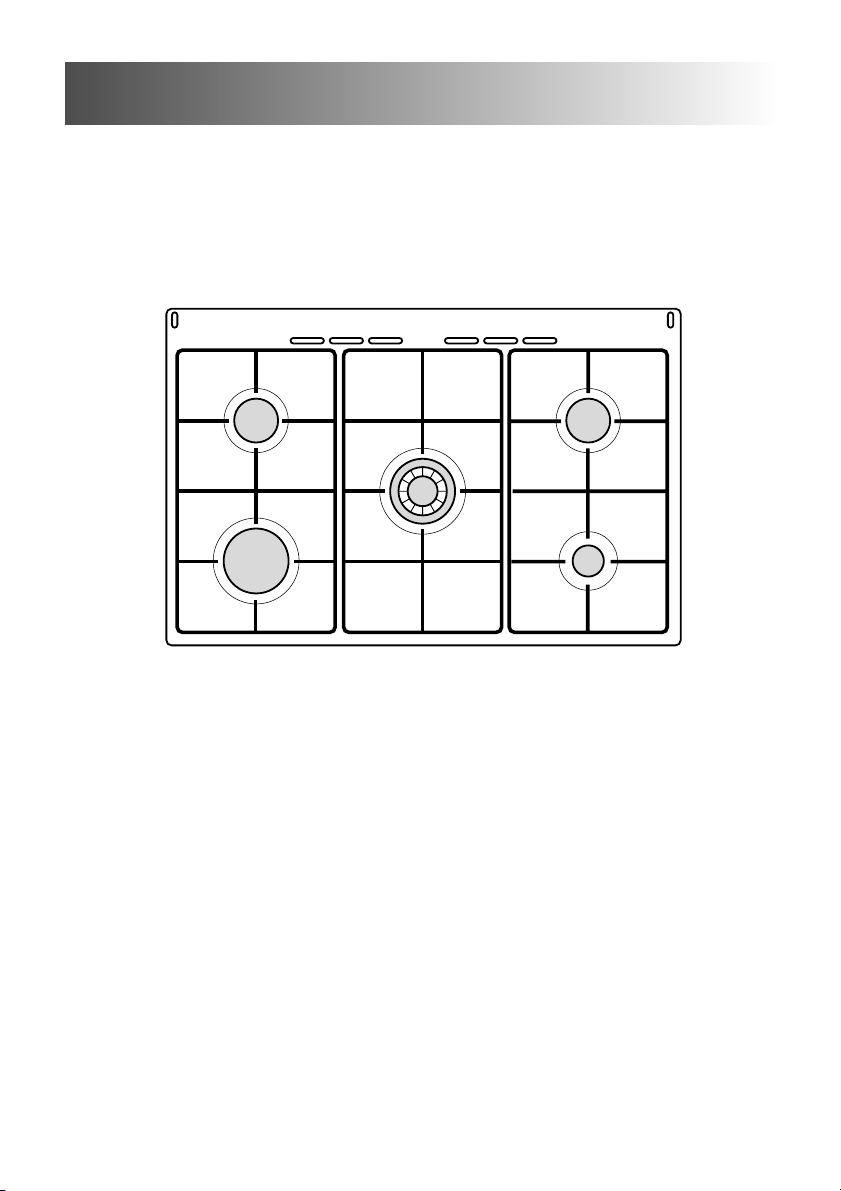
1 - COOKING HOB
1 - COOKING HOB
1. Auxiliary burner (A) - 1,00 kW
2. Semi-rapid burner (SR) - 1,90 kW
3. Rapid burner (R1) - 3,15 kW
4. Double- ring burner (PB) - 3,45 kW
Fig. 1.1
2
4
2
1
3
TECHNICAL FEATURES
– Gas cooker
Category II 2H3+
Class 1
– Glass lid
Page 5
5
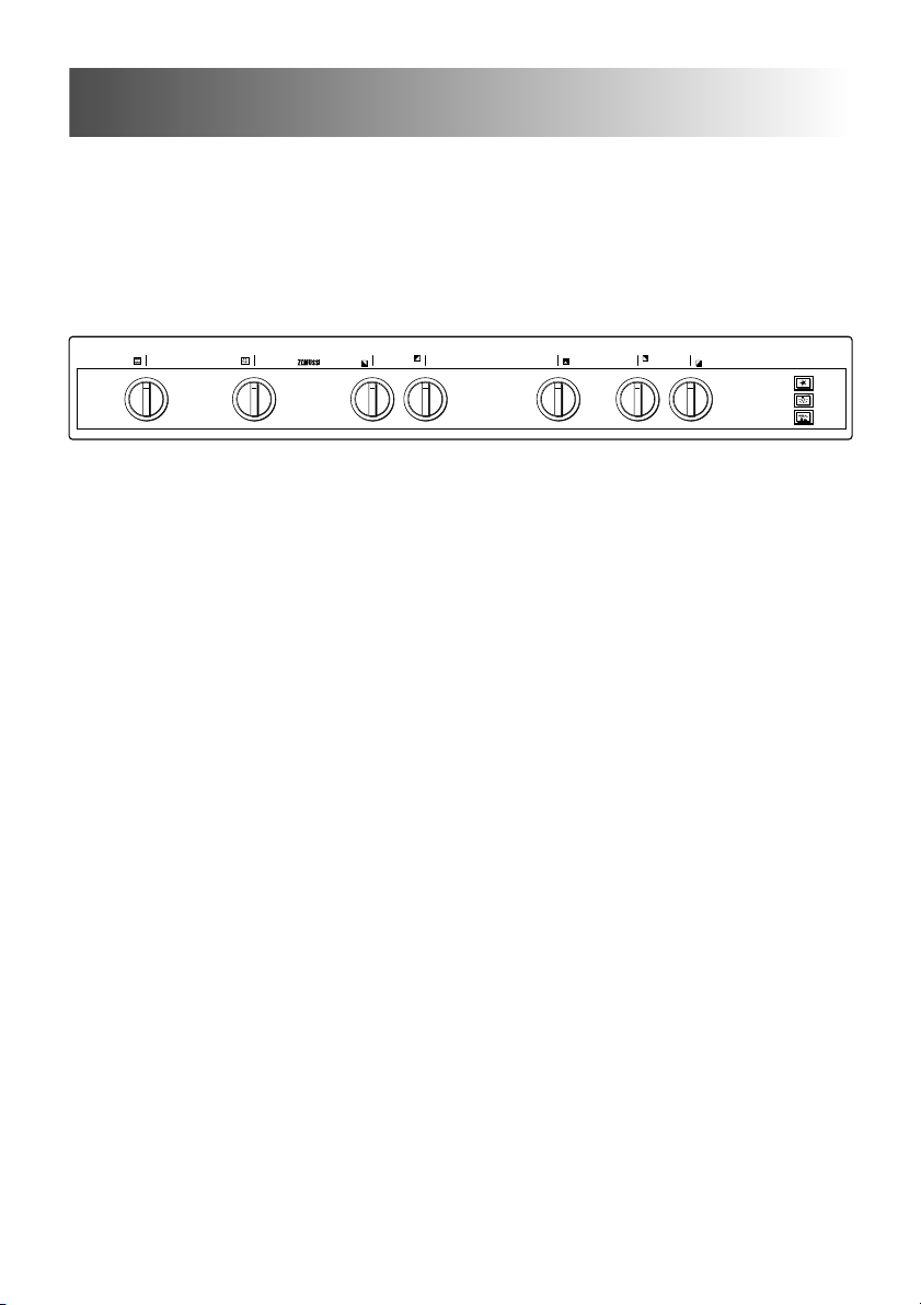
Pushbuttons:
8. Rotisserie switch
9. Oven light switch
10. Electric ignition pushbutton (cooktop burners only)
2 - CONTROL PANEL
1. Front right burner control knob
2. Rear right burner control knob
3. Central double-ring burner control knob
4. Rear left burner control knob
5. Front left burner control knob
6. 60’ timer knob
7. Gas oven/gas grill thermostat control knob
2 - CONTROL PANEL
1
10
9
8
23
45
6
7
Fig. 2.1
Z 9060 W
1
0
1
0
Page 6
6
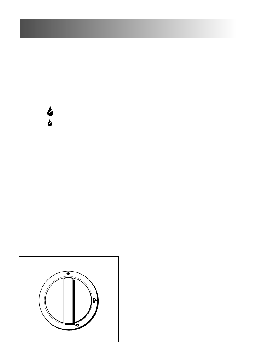
3 - USE OF COOKING HOB
Fig. 3.1
GAS BURNERS
Each burner is controlled by a gas tap
assuring the opening and the closing of
the gas supply.
Make the symbols printed on the knob to
match with the indicator on the control
panel to obtain:
– symbol
● : off
– symbol : full on (nominal rate)
– symbol : reduced rate
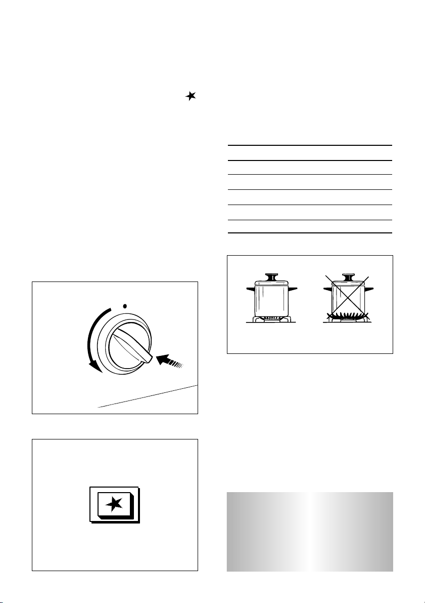
To light one of the gas burners, hold a
flame (i.e. a match) close to the top part
of the burner, push in and turn the relative knob in an anti-clockwise direction,
pointing the large flame symbol (i.e.
max. gas flow) towards the indicator on
the control panel.
To reduce the gas flow to minimum,
rotate the knob further anti-clockwise to
point the small flame symbol towards
the control panel indicator.
The maximum aperture position permits
rapid boiling of liquids, whereas the
minimum aperture position allows slower
warming of food or maintaining boiling
conditions of liquids.
Other intermediate operating adjustments can be achieved by positioning
the indicator between the maximum and
minimum aperture positions, and never
between the maximum aperture and
closed positions.
Page 7
7
CHOICE OF THE BURNER
On the control panel, near every knob,
there is a diagram that indicates which
burner is controlled by that knob.
The suitable burner must be chosen
according to the diameter and the
capacity used.
As an indication, the burners and the
pots must be used in the following way:
It is important that the diameter of the
pot be suitable to the potentiality of the
burner so as not to compromise the high
output of the burners and therefore
energy waste.
A small pot on a large burner does not
give you a boiling point in a shorten
amount of time since the capacity of
heat absorption of a liquid mass
depends on the volume and the surface
of the pot.
Fig. 3.4
N.B. When the cooker top is not
being used, set the gas knobs
to their closed positions and
also close the cock valve on
the gas bottle or the main gas
supply line.
BURNERS POT DIAMETER
Auxiliary 12 - 16 cm
Semi-rapid 16 - 22 cm
Rapid 20 - 24 cm
Double-ring up to 30 cm
do not use pans with concave or convex bases
Fig. 3.2
ELECTRIC SPARK IGNITION
To light the burner you have to rotate
the knob corresponding to the specific
burner to the maximum flame position
(large flame symbol) and press the ignition button marked by the symbol
(fig. 3.3).
The sparks produced by the electrodes
situated next to the burner will light the
selected burner.
If conditions of the local gas supply
makes it difficult to light the gas burner
with the knob set to the high flame
position, rotate the knob to the lower
flame position and repeat the ignition.
If the burner flame should go out
accidentally wait for at last 1 minute
before re-light the burner.
Fig. 3.3
Page 8

8
GENERAL FEATURES
The oven is furnished completely clean;
it is advisable, however, upon first use,
to turn the oven on to the maximum temperature (position 10) to eliminate possible traces of grease from the oven burner. The same operation should be followed for grill burner.
The gas oven is provided with two burners:
a) Oven burner, mounted on the lower
part of the oven (wattage: 6,20 kW)
b) Grill burner, mounted on the upper
part of the oven (wattage: 4,65 kW).
OVEN BURNER
It carries out normal “oven cooking”.
The gas flow to the burner is regulated
by a thermostat which allow to maintain
the oven temperature constant.
The control of the temperature is assured by a thermostatic probe positioned
inside the oven.
The probe must be always kept in its
housing, in a clean condition, as an
incorrect position or encrustment may
cause an alteration in the control of the
temperature.
4 - GAS OVEN
The glass on the oven door reaches high temperatures during
operation.
Keep children away.
The cooker lid must be kept
open when the gas oven is in
use.
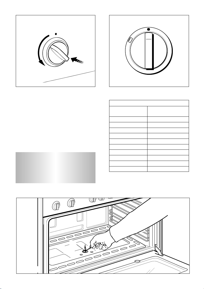
IGNITION OF THE OVEN BURNER
1
– Open the oven door to the full
extent.
WARNING: Risk of explosion!
The
oven door must be open during this
operation.
2
– Light the oven burner by applying a
flame to the hole ‘A’, as shown in fig.
4.2.
ATTENTION: Never turn the thermostat before approaching a flame to
the hole “A” of the floor of the oven.
3 – Press in the oven control knob (fig.
4.1) and turn counter-clockwise to
position 10. Keep the knob pressed.
Never continue this operation for
more than 15 seconds. If the burner has still not ignited, wait for
about 1 minute prior to repeating
the ignition.
4 – After lighting the burner, wait a few
seconds before releasing the knob
(until the safety valve stays open).
5 – Gently close the oven door and set
the oven control knob to the required
temperature.
If the flame extinguishes for any reason,
the safety valve will automatically shut
off the gas supply to the burner.
To re-light the burner, first turn the oven
control knob to position ●, wait for at
least 1 minute and then repeat the
lighting procedure.
Page 9
9
1
Fig. 4.3
Table 4.4
Fig. 4.2
A
For efficient oven preheating, we
recommend that grill trays and
racks are removed from the oven
and replaced after about 15 minutes.
THERMOSTAT GRADE TABLE
Thermostat Oven
indicator temperature
1 150 °C
2 165 °C
3 180 °C
4 195 °C
5 210 °C
6 225 °C
7 240 °C
8 255 °C
9 270 °C
10 285 °C
Fig. 4.1
THERMOSTAT
The numbers 1 to 10 printed on the
knob (fig. 4.3) indicate the increasing
oven temperature value (see table 4.4).
To regulate the temperature, set the
chosen number onto the control panel
indicator (or onto the knob indicator).
2
3
4
10
9
8
5
6
7
Page 10

10
OVEN COOKING
Before introducing the food, preheat the
oven to the desired temperature.
For a correct preheating operation, it is
advisable to remove the tray from the
oven and introduce it together with the
food, when the oven has reached the
desired temperature.
Check the cooking time and turn off the
oven 5 minutes before the theoretical
time to recuperate the stored heat.
COOKING EXAMPLES
Temperatures and times are approximate as they vary depending on the quality
and amount of food.
Remember to use ovenproof dishes and
to adjust the oven temperature during
cooking if necessary.
DISHES TEMPERATURE
Lasagne 190°
Baked pasta 190°
Pizza 220°
Creole rice 190°
Baked onions 190°
Spinach crêpes 185°
Potatoes baked in milk 185°
Stuffed tomatoes 180°
Cheese soufflé 170°
Roast veal 180°
Grilled veal chops 210°
Chicken breasts with tomato 180°
Grilled chicken - roast chicken 190°
Veal loaf 175°
Roast beef 170°
Fillet of sole 175°
Aromatic hake 170°
Beignets 160°
Ring cake 150°
Plum tart 170°
Jam tartlets 160°
Sponge cake 170°
Sweet dough 160°
Sweet puffs 170°
Plain sponge cake 170°
Page 11

11
Fig. 4.5
Fig. 4.6
IGNITION OF THE GRILL BURNER
1 – Open the oven door to the full
extent.
WARNING: Risk of explosion!
The
oven door must be open during
this operation.
2 – Light the grill by applying a flame to
pipe of the grill burner (fig. 4.6).
ATTENTION: Never turn the thermostat before approaching a
flame to pipe of the grill burner.
3 – Press in the oven control knob (fig.
4.5) and turn clockwise to the position marked by the symbol .
Keep the knob pressed.
Never continue this operation for
more than 15 seconds. If the
burner has still not ignited, wait
for about 1 minute prior to repeating the ignition.
4 – After lighting the burner, wait a few
seconds before releasing the knob
(until the safety valve stays open).
Do not close completely the oven
door. The grill must always be used
with the oven door slightly open
(Fig. 4.7).
The oven door must always be kept
half-open when the grill is in operation. See specific instructions in the sec-
tion ‘USE OF THE GRILL’.
If the flame extinguishes for any reason,
the safety valve will automatically shut
off the gas supply to the burner.
To re-light the burner, first turn the oven
control knob to position ●, wait for at
least 1 minute and then repeat the
lighting procedure.
Attention: the oven door becomes
very hot during operation.
Keep children away.
It is recommended that you do not
grill for longer than 30 minutes at any
one time.
Page 12

12
Fig. 4.7
A
USE OF THE GRILL
Very important: the grill must always
be used with the oven door ajar
(Fig. 4.7).
Mount shield “A” which serves to protect the control panel from the heat.
Turn on the grill, as explained in the preceding paragraphs and let the oven
preheat for about 5 minutes with the
door ajar.
Introduce the food to be cooked, positioning the rack as close to the grill as possible.
The dripping pan should be placed
under the rack to catch the cooking
juices and fats.
Attention: the oven door becomes very hot during operation.
Keep children away.
ROTISSERIE (Fig. 4.8)
This is used for spit roasting under the
grill and comprises:
– an electric motor fitted to the rear of
the oven
– a stainless steel skewer provided with
slide-out heatless handgrip and two
sets of adjustable forks
– a skewer support to be fitted in the
middle runner.
This spit roaster is operated by the
switch indicated by the symbol on
the control panel (fig. 4.9).
0
1
0
1
USE OF THE ROTISSERIE
Very important: the rotisserie must
always be used with the oven door
ajar and with shield “A” mounted
(Fig. 4.7).
– Insert the tray into the lowest rack
holders of the oven and insert the rod
support into the intermediate rack
holders.
– Put the meat to be cooked onto the
rod, being careful to secure it in the
center with the special forks.
– Insert the rod into the side gear
opening “P”
– Remove the grip “H” by turning it to
the left
– Insert completely the rotisserie
support; the shaft “S” must be inserted
in the spit motor collar “G”
It is recommended that you do not
grill for longer than 30 minutes at any
one time.
Page 13

13
OVEN LIGHT
The cooker is equipped with a light that
illuminates the oven to enable visually
controlling the food that is cooking.
This light is controlled by a switch on the
control panel (fig. 4.10).
Fig. 4.10
Fig. 4.9
Fig. 4.8
G
S
H
P
1
0
1
0
Page 14

14
GENERAL ADVICE
– When the appliance is not being used,
it is advisable to keep the gas tap
closed.
– Every now and then check to make
sure that the flexible tube that
connects the gas line or the gas
cylinder to the appliance is in perfect
condition and eventually substitute it if
it shows signs of wearing or damage.
– The periodical lubrication of the gas
taps must be done only by specialized
personnel.
– If a gas tap jams, do not try to force
it. Seek technical assistance.
– Important:
Before any operation of cleaning
and maintenance disconnect the
appliance from the electrical
network.
Fig. 5.1
5 - MINUTE COUNTER
MINUTE COUNTER (Fig. 5.1)
The minute counter is a timed acoustic
warning device which can be set for a
maximum of 60 minutes.
The knob (Fig. 5.1) must be rotated
clockwise as far as the 60 minute position and then set to the required time by
rotating it anticlockwise.
Do not use a steam cleaner
because the moisture can get into
the appliance thus make it unsafe.
50
10
40
20
30
Page 15

15
Fig. 6.1
S
D
R
GLASS LID
For cleaning purposes, the lid can be
easily removed upwards once taken to
the upright position.
Should the hinges slip off, replace them
in their housing being careful that:
– The right housing must receive the
hinge marked “D” while the left housing must receive the hinge marked “S”
(Fig. 6.1)
6 - CLEANING AND MAINTENANCE
REGULATING OF THE BALANCE
Lower the lid and check the correct balance. While opened at 45° it should
hang up.
The springs of the hinges can be adjusted if necessary by turning the screws
“R” clockwise (fig. 6.1).
Do not close the cooker lid when
the burners are still hot and
when the oven is on or still hot.
Do not rest hot pans or heavy
objects on the cooker lid.
Remove any spillages from the
surface of the cooker lid before
opening.
Page 16

16
CLEANING
All the enamelled parts must be cleaned
with a sponge and soapy water or other
non-abrasive products.
Dry preferably with a soft cloth.
Acidic substances like lemon juice,
tomato sauce, vinegar etc. can damage
the enamel if left too long.
STAINLESS STEEL, ALUMINIUM
PARTS AND SILK-SCREEN PRINTED
SURFACES
Clean using an appropriate product.
Always dry thoroughly.
IMPORTANT: these parts must be cleaned very carefully to avoid scratching
and abrasion. You are advised to use a
soft cloth and neutral soap.
CAUTION: Do not use abrasive substances or non-neutral detergents as
these will irreparably damage the protective surface.
REPLACING THE OVEN LIGHT BULB
Switch the cooker off at the mains.
Unscrew and replace the bulb with
another one resistant to high temperatures (300°C), voltage 230 V (50 Hz), 15
W, E14.
INSIDE OF OVEN
This must be cleaned every time it is
used.
Remove and refit the side runner frames
as described on the next chapter.
With the oven warm, wipe the inside
walls with a cloth soaked in very hot
soapy water or another suitable product.
The bottom of the oven, side runner frames, tray and rack can be removed and
washed in the sink.
BURNERS
They can be removed and washed with
soapy water only.
They will remain always perfect if cleaned
with products used for silverware.
After cleaning or wash, check that burnercaps and burner-heads are dry before placing them in the respective housings.
Special attention has to be paid in
order not to exchange the housing of
the two small burners shown in fig. 6.2.
It is absolutely necessary to check the
perfect housing of the burner-ring as an
incorrect housing may cause serious
inconvenience.
Check also that the electrodes for ignition be always clean in order to ensure a
regular spark shooting.
Burner-cap ring
partially drilled
Burner-cap ring
fully drilled
Fig.
6.2
Page 17

17
STORAGE COMPARTMENT
The storage compartment is accessible
through the pivoting panel (fig. 6.4).
Fig. 6.4
Fig. 6.3
OVEN DOOR
The internal glass panel can be easily
removed for cleaning by unscrewing the
4 retaining screws (Fig. 6.3)
Do not store flammable material in
the oven or in the storage
compartment.
Page 18

18
The oven door can easily be removed as
follows:
– Open the door to the full extent (fig.
6.5A).
– Attach the retaining rings to the hooks
on the left and right hinges (fig. 6.5B).
– Hold the door as shown in fig. 6.5.
– Gently close the door and withdraw the
lower hinge pins from their location
(fig. 6.5C).
– Withdraw the upper hinge pins from
their location (fig. 6.5D).
– Rest the door on a soft surface.
– To replace the door, repeat the above
steps in reverse order.
Fig. 6.5
Fig. 6.5D
Fig. 6.5C
Fig. 6.5B
Fig. 6.5A
REMOVING THE OVEN DOOR
Page 19

19
ASSEMBLY AND DISMANTLING OF
THE SIDE RUNNER FRAMES
– Fit the side runner frames into the
holes on the side walls inside the
oven (Fig. 6.6).
– Slide the tray and rack into the run-
ners as shown in Fig. 6.7.
– To dismantle, operate in reverse
order.
OVEN FLOOR
The oven floor “F” (fig. 6.8) can be easily
removed to facilitate cleaning.
Remember to replace the floor correctly
afterwards.
Be careful not to confuse the tray “L”
with the oven floor “F”.
Fig. 6.6
Fig. 6.8
L
F
Fig. 6.7
Page 20

20
IMPORTANT
– Cooker installation, regulation and conversion to other gas types must only be carried
out by QUALIFIED TECHNICIANS and in compliance with the local safety stan-
dards. Failure to observe this rule will invalidate the warranty.
– The electrical mains outlet, if located behind the cooker, must not be higher than 18 cm
above the floor level.
– The surfaces of adjacent furniture and walls must be capable of withstanding tempera-
tures in excess of 75˚C.
– Some appliances are supplied with a protective film on steel and aluminium parts.
This film must be removed before using the cooker.
Advice for
the
installer
Page 21

21
Fig. 7.1
500 mm
300 mm
20 mm
20 mm
800 mm
500 mm
INSTALLATION
The cooker afford class ‘1’ protection against overheating surrounding surfaces.
A space of at least 2 cm must be left between the cooker and any adjacent furniture,
which must not exceed the height of the cooktop (fig. 7.1).
The surfaces of adjacent furniture must be capable of withstanding temperatures
up to 75˚C.
7 - INSTALLATION
Page 22

22
Fig. 7.4
Fig. 7.2
FITTING THE ADJUSTABLE FEET
The adjustable feet must be fitted to
the base of the cooker before use.
Rest the rear of the cooker on a
piece of the polystyrene packaging
exposing the base for the fitting of
the feet.
Fit the 4 legs by screwing them tight
into the support base as shown in
picture 7.3.
WARNING
When raising cooker to upright position always ensure two people carry
out this manoeuvre to prevent damage to the adjustable feet (fig. 7.4).
Fig. 7.3
Page 23

23
Fig. 7.5
Fig. 7.6
Fig. 7.7
WARNING
Be carefull: DO NOT LIFT
the cooker by
the door handle when raising to the
upright position (fig. 7.5).
LEVELLING THE COOKER
The cooker may be levelled by screwing
the lower ends of the feet IN or OUT (fig.
7.7)
WARNING
When moving cooker to its final position
DO
NOT DRAG (fig. 7.6).
Lift feet clear of floor (fig. 7.4).
Page 24

24
CHOOSING SUITABLE
SURROUNDINGS
In the room chosen to accommodate the
gas appliance, there must be an adequate natural draft to allow combustion of
the gas.
The natural draft must be produced
directly by one or more vents made in
the external walls and providing a total
opening of at least 100 cm
2
.
If the appliance does not have a noflame safety device this opening must
have an area of at least 200 cm
2
.
The vents must be positioned close to
the floor, preferably on the opposite side
to the combustion discharge outlet and
must be designed in such a way that
they cannot be obstructed either from the
inside or the outside.
When it is not possible to provide the
necessary vents, the draft may be supplied from an adjacent room, ventilated in
the required manner, provided it is not a
bedroom or an area at risk.
In this event, the door of the kitchen must
be opened to allow the draft to enter the
room.
DISCHARGING PRODUCTS OF
COMBUSTION
Extractor hoods connected directly to the
outside must be provided, to allow the
products of combustion of the gas appliance to be discharged (fig. 7.8).
If this is not possible, an electric fan may
be used, attached to the external wall or
the window; the fan should have a
capacity to circulate air at an hourly rate
of 3-5 times the total volume of the
kitchen (fig. 7.9).
The fan can only be installed if the room
has suitable vents to allow air to enter,
as described under the heading
“Choosing suitable surroundings”.
Fig. 7.8
Fig. 7.9
Air vent
Air vent
Extractor hood
for products of
combustion
Electric fan to
extract products
of combustion
H min 650 mm
Page 25

25
Plug
Fig 8.1
The walls adjacent to the cooker
must be of material resistant to
heat.
INSTALLATION
The connection must be executed by a
qualified technician according to the
relevant standards.
The appliance is predisposed and
adjusted to operate with the gas
indicated on the specifications plate
applied onto the appliance.
GASES
The gases used for the operation of
cooking appliances may be grouped by
their characteristics into two types:
– G20
– G30 / G31
If the appliance must be operated with a
gas different than that indicated on the
plate, it is necessary to execute the
following operations:
– Gas connection
– Replacement of the top injectors
– Regulating of the primary air of the
top burners
– Adjustment of the minimum of the
top burners
– Replacement of the injector of oven
burner
– Replacement of the injector of grill
burner
– Primary air of oven burner
– Primary air of grill burner
– Adjustment of the oven burner
minimum
8 - GAS SECTION
Page 26

26
These operations must be carefully fulfilled as follows.
GAS CONNECTION
– Connect the cooker to the gas mains
utilizing rigid or flexible pipes.
– The connection must be executed to
the rear of appliance (left or right) (fig.
8.1); the pipe do not cross the cooker.
– The unused end inlet pipe of the cook-
er (left or right) must be closed with the
plug interposing the gasket.
Natural gas G20
– Fit up the holder “C” interposing gasket
“D”.
– Connect the cooker to the gas net by a
suitable rubber tube (inside diameter
15 mm).
M
ake sure the tube is snugly fit at both
ends and use a standard tube clamp (not
supplied) to fasten it.
L.P.G. G30 / G31
– Fit up the holder “B” interposing gasket
“D”.
– Connect the cooker to the cylinder
pressure regulator by a suitable rubber
tube (inside diameter 6 mm).
M
ake sure the tube is snugly fit at both
ends and use a standard tube clamp (not
supplied) to fasten it.
The rubber tube:
- must be as short as possible, without contractions or kinks;
- must be easy to inspect along its
entire length to check its wear;
- must never be at any point in its
length in contact with the “hot” parts
of the cooker.
Gas connection for:
Cat: II 2H3+
The fitting (fig. 8.2) is made up of:
– 1 adapter “C” for G20
– 1 adapter “B” for G30/G31
– gasket “D”
D
B C
Fig. 8.2
Fig. 8.3
Page 27

27
B
D
B
A
E
E
Fig. 8.4a
C
C
B
B
B
B
Fig. 8.4b
IMPORTANT:
To replace the adapters it is necessary
to operate with 2 spanners (fig. 8.3).
After connecting to the mains, check
that the couplings are correctly sealed, using soapy solution, but never a
naked flame.
From time to time check to make sure
that the rubber tube is in perfect condition and substitute it at printed due
date or if it shows signs of wearing or
damage.
D
REPLACEMENT OF THE TOP
INJECTORS
To replace the injectors, raise the cooktop in the following manner:
– Pull the lid “A” upwards to remove
from the cooker.
– Remove the pan supports and burners
from the cooktop.
– Remove the 4 screws “B” and the cen-
tral screw “C” (fig. 8.4a - fig. 8.4b).
– Remove the two hinge brackets “D” by
pulling them upwards.
– Raise the cooktop in the direction
shown by the arrow “E”.
– Prop the cooktop up.
Page 28

28
AIR VENT NECESSARY FOR GAS COMBUSTION = (2 m
3
/h x kW)
BURNERS
Air vent necessary [m3]
Auxiliary (A) 2,00
Semirapid (SR)
3,80
Rapid 6,30
Double-ring 6,90
Oven 12,40
Grill 9,30
TABLE FOR THE CHOICE OF THE INJECTORS
Cat: II 2H3+
Auxiliary (A) 1,00 0,30 27 50 3
*
Semirapid (SR)
1,90 0,38 29 67 5,7
*
Rapid 3,15 0,60 39 86
Fully open
*
Double-ring 3,45 0,85 47 92
Fully open
*
Oven 6,20 1,30 58 120
8
*
Grill 4,65 – – 107
Fully open
*
Nominal
power
[kW]
Reduced
power
[kW]
Tube ring
opening [mm]
Ø injector
[1/100 mm]
By-pass
[1/100 mm]
G 30 / G 31
28-30/37 mbar
BURNERS
Auxiliary (A) 1,00 0,30 72 1
*
Semirapid (SR)
1,90 0,38 100 2
*
Rapid 3,15 0,60 130
5
*
Double-ring 3,45 0,85 135
5
*
Oven 6,20 1,30 180
1,5
*
Grill 4,65 – – 165
3
*
Nominal
power
[kW]
Reduced
power
[kW]
Tube ring
opening [mm]
Ø injector
[1/100 mm]
By-pass
[1/100 mm]
G 20
20 mbar
BURNERS
Adjusted
*
Reference value
Page 29

29
Fig. 8.5
M
J
A
ADJUSTMENT OF PRIMARY AIR OF
TOP BURNERS
By operating on the screw “M”, reset the
air adjuster “A” according to the instructions indicated on the table for the
choice of the injectors, where the distance between injector and air adjuster
is recommended (in mm).
Before lowering the cooktop, set the
burners on their sites and light them in
order to check whether the flames are
correct, as per the specifications given
in the next page. In case of uncorrect
flame, lift or lower the air adjuster.
Flame Flame Flame
faulty in correct with excess
primary air primary air
long, yellow clear short and sharp
and interior blue too blue interior
trembling cone cone tending to
detach
CAUSE
air regulating correct air regulating
tube, too distance of tube, too
closed the tube open
REPLACEMENT OF THE TOP
INJECTORS
(Fig. 8.5)
– Loose the screw “M” of each injector
and fully raise the adjusting air tube
“A”.
– By a polygonal 7 spanner, remove the
injector “J” from their housing and
replace it by the proper one according
to the kind of gas (see injectors table).
Fig. 8.6
ADJUSTMENT OF THE MINIMUN OF
THE TOP BURNERS
Considering that in the minimum position the flame must have a length of
about 4 mm and must remain lit even
with a brusque passage from the maximum position to that of minimum.
The flame adjustment is done in the following way:
– Turn on the burner
– Turn the tap to the MINIMUM position
– Take off the knob
– With a small flat screwdriver turn the
screw inside the tap rod to the correct
regulation (fig. 8.6).
Normally for G30/G31 gas, tighten up
the regulation screw.
D
Page 30

30
OVEN BURNER AND GRILL BURNER
REPLACEMENT OF INJECTORS
a) oven burner
– Lift and remove the lower panel inside
the oven.
– Unscrew and remove the burner
securing screw A (fig. 8.7).
– Slacken screw B (fig. 8.7).
– Withdraw the burner in the manner
shown in figure 8.8, and rest it inside
the oven. Take care not to damage
the wire to the safety valve probe.
– Using a 10 mm box spanner, unscrew
the injector (indicated by the arrow in
fig. 8.8) and replace with a new injec-
tor selected in accordance with the
“
TABLE FOR THE CHOICE OF THE
INJECTORS
”; then replace the burner
repeating the above steps in reverse
order.
A
B
Fig. 8.7
Fig. 8.8
Page 31

31
b) grill burner
– Unscrew and remove the burner
securing screw ‘C’ (fig. 8.9).
– Slacken screw ‘D’ (fig. 8.9).
– Move the burner in the manner shown
in figure 8.10.
Take care not to damage the wire to
the safety valve probe.
– Using a 10 mm box spanner, unscrew
the injector (indicated by the arrow in
fig. 8.10) and replace with a new injec-
tor selected in accordance with the
“
TABLE FOR THE CHOICE OF THE
INJECTORS
”; then replace the burner
repeating the above steps in reverse
order.
Fig. 8.10
Fig. 8.9
C
D
Page 32

32
Fig. 8.11
Fig. 8.12
Ring opening
(see ‘Injector Table)
REGULATION OF AIR SUPPLY TO
OVEN AND GRILL BURNERS
Using a cross-head screwdriver, slacken
the screw securing the air flow regulation collar (fig. 8.11 and 8.12) and move
the collar forward or backward to
increase or reduce the air aperture in
accordance with gas type and the indications in the “
TABLE FOR THE
CHOICE OF THE INJECTORS
”.
Light the burner and check the flame.
Page 33

33
Fig. 8.13
G
ADJUSTMENT OF THE OVEN
BURNER MINIMUM
This needs to be done only for the oven
burner (the grill is a fixed capacity) by
acting on the thermostat in the following
way:
– turn on the burner by setting the ther-
mostat knob on position 10
– unscrew the by-pass screw (fig. 8.13)
about three times by a flat screwdriver
– let the oven heat up for about 10 min-
utes, then bring the thermostat to position 1 (minimum) to operate the thermostat by-pass
– slowly screw the by-pass screws “G”
(fig. 8.13) until you obtain a flame of 34 mm in height.
N.B. For G30/G31 the by-pass screw
must be fixed thoroughly.
LUBRICATION OF THE GAS TAPS
If the gas taps are not working correctly,
call the After-Sales Service.
Flame correct
Flame faulty in
primary air
Flame with excess
primary air
IMPORTANT
All interventioni regarding installation maintenance and conversion of the appliance must be
fulfilled with original factory
parts.
The manufacturer declines any
liability resulting from the noncompliance of this obligation.
Page 34

34
N.B. For connection to the mains, do
not use adapters, reducers or branching devices as they can cause
overheating and burning.
If the installation requires alterations to
the domestic electrical system or if the
socket and appliance plug are incompatible, call an expert.
He should also check that the socket
cable section is suitable for the power
absorbed by the appliance.
IMPORTANT: The cooker must be
installed in accordance with the
manufacturer’s instructions.
Incorrect installation, for which the
manufacturer accepts no responsibility, may cause damage to persons, animals and things.
GENERAL
– Connection to the mains must be car-
ried out by qualified personnel in
accordance with current regulations.
– The appliance must be connected to
the mains checking that the voltage
corresponds to the value given in the
rating plate and that the electrical
cable sections can withstand the load
specified on the plate.
– The cooker is supplied without a
power supply plug and therefore if
you are not connecting directly to the
mains, a standardized plug suitable
for the load must be fitted.
– The plug must be connected to an
earthed socket in compliance with
safety standards.
– The appliance can be connected
directly to the mains placing an omnipolar switch with minimum opening
between the contacts of 3 mm
between the appliance and the mains.
– The power supply cable must not
touch the hot parts and must be positioned so that it does not exceed 75°C
at any point.
– Once the appliance has been instal-
led, the switch or socket must always
be accessible.
The connection of the appliance
to earth is mandatory.
The manufacturer declines all
responsability for any inconvenience resulting from the inobservance of this condition.
9 - ELECTRICAL SECTION
Page 35

35
FEEDER CABLE SECTION TYPE
HO5RR-F
230 V 3 x 0,75 mm
2
Fig. 9.2
ELECTRICAL FEEDER CABLE
CONNECTION
To connect the supply cable:
- Remove the screws securing the
cover “A” on the rear of the cooker
(fig. 9.1).
- Feed the supply cable through the
cable clamp “D”. The supply cable
must be of a suitable size for the current requirements of the appliance;
see the section “Feeder cable section” (fig. 9.1).
- Connect the wires to the terminal
block “B” as shown in the diagram in
figure 9.2; or connect the phase wires
to the terminal block “B” and the earth
wire to the terminal PE (fig. 9.1) as
shown in figure 9.2.
- Take up any slack in the cable and
secure with the cable clamp “D”.
- Replace the cover “A”.
Fig. 9.1
D
B
PE
A
Switches igniter and electrodes can be
replaced after lifting the cooktop, following the instructions shown in the chapter
‘REPLACEMENT OF THE TOP INJECTORS”
REMPLACEMENT OF ELECTRICAL
COMPONENTS SITUATED UNDER
THE COOKTOP
Before effecting any intervention on
the electrical parts of the appliance,
the connection to the network must
be interrupted.
230 V
L
PEN
1
(L2)
Page 36

The manufacturer cannot be held responsible for possible inaccuracies due to printing or
transcription errors in the present booklet.
The manufacturer reserves the right to make all modifications to its products deemed
necessary for manufacture or commercial reasons at any moment and without prior notice, without jeopardising the essential functional and safety characteristics of the appliances.
Cod. 1101939
ß2
 Loading...