


WIRING CONNECTION DIAGRAM
Red
Blue
4
5
6
Yellow
White
Black
Green
DISPLAY
ELECTRIC CATCH
WARRANTY
24-month commercial warranty by the manufacturer
Reseller’s stamp and signature
3. The BUYER shall make all warranty claims in writing at the point of sale or to ZAMEL Sp. z o.o.
4. ZAMEL Sp. z o.o. will examine each warranty claim as regulated by the applicable provisions of the Polish law.
5. The form of warranty claim resolution, i.e. replacement, repair or refund of the price of purchase, shall be decided
6. This warranty does not exclude, limit or suspend any rights of the BUYER arising from the statutory
with date of sale
by ZAMEL Sp. z o.o.
or regulatory laws concerning implied warranty for defects of sold goods.
1. ZAMEL Sp. z o.o. Gives a 24-month warranty for the goods it sells.
2. The warranty given by ZAMEL Sp. z o.o. does not cover:
a) mechanical damage caused by transport, loading/unloading
or other circumstances;
b) damage caused by improper installation or operation of the goods
manufactured by ZAMEL Sp. z o.o.;
c) damage caused by any modications made by the BUYER
or any third party to the sold goods or to the equipment required
for the proper functioning of the sold goods;
d) damage caused by any force majeure event or another fortuitous
event beyond any reasonable control of ZAMEL Sp. z o.o.;
e) the power supply (batteries) included (if any) with the device
as sold.
ENTRANCE PANEL VO-811B / VO-811S
Thank you for buying this product from Zamel.
Zamel shall not accept any liability for any results of damage and/or accidents
caused by non-intended use of the product.
Before attempting installation of this product, please read and understand
the entire Operating Manual to comply with the intended use.
Do not open or tamper with the product without prior authorization.
Otherwise your warranty rights for this product will be void.
SPECIFICATIONS
• Surface-mounted
• Vandal-resistant zinc alloy housing
• 800 TVL resolution
• ¼” CMOS colour camera
• Night-time IR illumination
• Dust and water proof: IP66
• Operating temperature: -30°C to +60°C
• Dimensions: 128 x 43 x 16 mm
• 110° wide-angle camera
• Video output: 1Vp-p75Ω
• Supply voltage: 10-15V DC
• Input power: 2.5 W
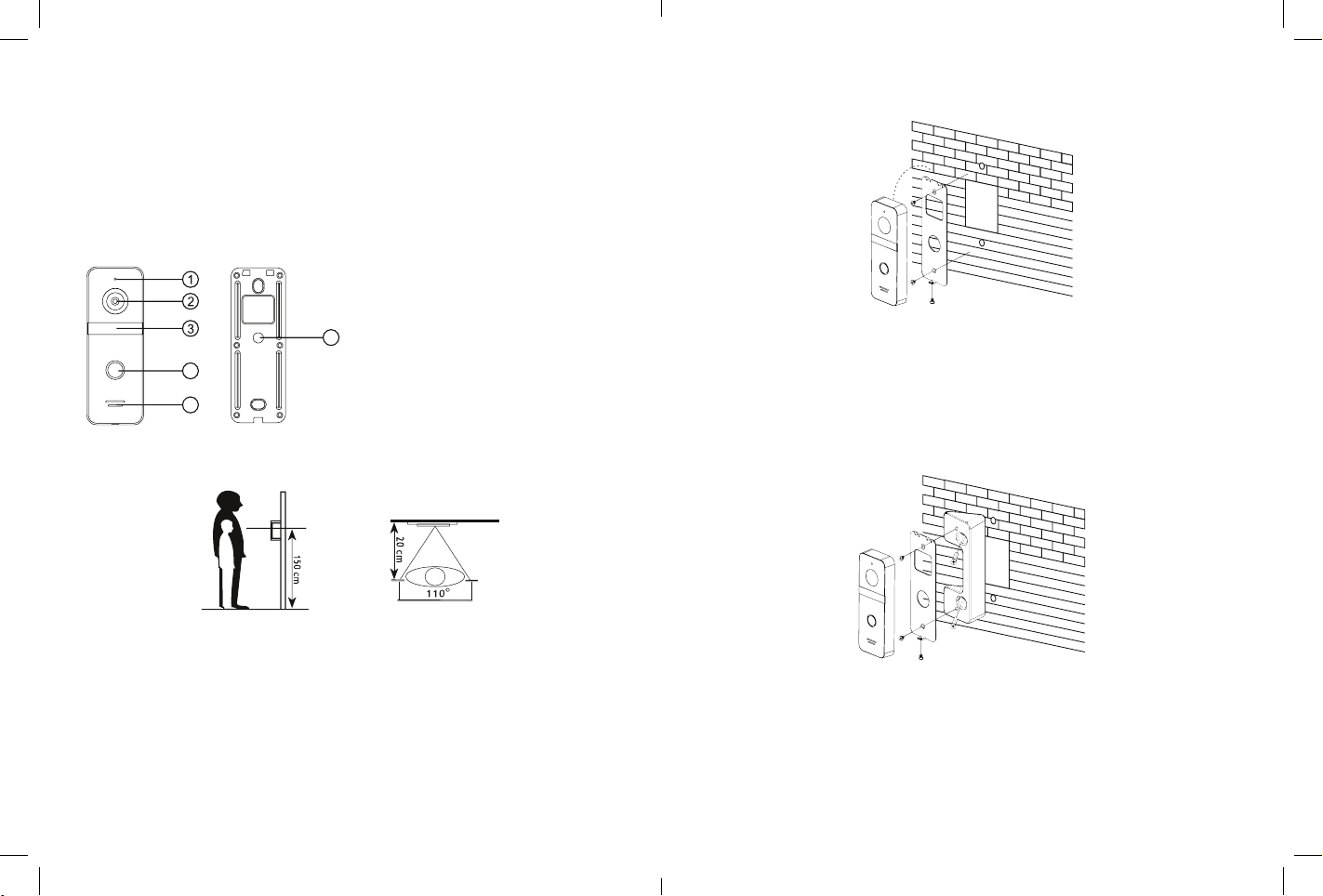
PRODUCT DESCRIPTION
1. Microphone
2. Camera
3. Night-time IR illuminator
6
4. Call button
4
5. Speaker
6. Wiring harness receptacle
5
FRONT BACK
INSTALLATION
1. Use the wiring connection diagram and verify that all wiring connections are correct.
2. Choose a suitable location in which to install the entrance panel. An installation height
between 1.5 and 1.6 m above the ground is recommended.
3. The entrance panel video camera should be away from direct sunlight and deep shadows.
4. Verify that the power supply voltage is OFF before wiring the device.
5. Switch on the supply voltage of the device when completely installed.
6. Seal the back plate edges of the entrance panel of the complete installation surface with
a waterproof silicone product during the installation. This will prevent condensation
occurring between the entrance panel and its installation surface in certain weather
conditions. Condensation on the surfaces causes a risk of corrosion of the electronic
components in the device and mechanical stress from freezing of the condensation at low
temperatures.
INSTALLATION DIAGRAM
A. Directly on a wall or a post
1. Select the installation height of the entrance panel and drill the mounting holes
on the installation surface at the desired height.
2. Remove the bracket by removing its lock screw.
3. Mount the bracket on the installation surface with wall plugs and their screws.
4. Pass the connection wiring end through the bracket and connect it to the entrance
panel wiring. Follow the wiring connection diagram.
5. Install the entrance panel on the bracket with the lock screw.
B. Directly on a wall or a post with the 30° angle console
1. Select the installation height of the entrance panel and drill the mounting holes
on the installation surface at the desired height.
2. Mount the 30° angle console on the installation surface with wall plugs and their screws.
3. Remove the factory bracket from the entrance panel back plate.
4. Install the removed bracket on the 30° angle console with the screws provided.
5. Pass the connection wiring end through the bracket and connect it to the entrance panel
wiring. Follow the wiring connection diagram.
6. Install the entrance panel on the bracket with the lock screw.
 Loading...