

Zamel DIP-01, DIP-02 INSTRUCTION MANUAL
DIP-01, DIP-02 DIMMER
Zakład Mechaniki i Elektroniki
J.W. Dzida, K. Łodzińska
ul. Zielona 27, 43-200 Pszczyna, Poland
Tel. +48 (32) 210 46 65, Fax +48 (32) 210 80 04
www.zamelcet.com, e-mail: marketing@zamel.pl
ZAMEL sp.j.
INSTRUCTION MANUAL
DESCRIPTION
The DIP-01, DIP-02 dimmers are designed
for incandescent lights intensity adjustment. It is possible to control light intensity
by means of a single pole push button. If
needed, it is possible to connect the push
buttons in parallel. The devices are capable of switching ON and OFF the light, and
fluent brightening up and dimming. The
dimmers are designed for mounting in a
junction box. By means of the dimmers
It is possible to control lighting systems in
a comfortable, convenient and economical
way. Additionally, the DIP-02 model is capable of storing light intensity level.
FEATURES
ی Incandescent lights intensity control,
ی Easy applicable together with any
existing electrical system,
ی Applicable together with single pole
push buttons, illuminated,
ی Maximum output power: 350 W,
ی Model with the light intensity storage
available (DIP-02),
ی Device triggering by means of the L
wire,
ی Series connection with a light source,
ی Casing designed for mounting in a
junction box.
TECHNICAL DATA
Power terminals: L(black), brown - in series with load
Rated voltage: 230 V~
Rated voltage tolerance: -15 ÷ +10 %
Rated frequency: 50 / 60 Hz
Rated current: 10 mA
Trigger terminals: IN(red)
Light intensity storage: - yes
Load supply indicator: red LED
Permissible load: 30 ÷ 300 W
Fuse technical specication: 5 x 20 mm, ultra-fast, 2 A / 250 V
Connection terminals quantity:
Connection wire section:
Operating temperature:
Operating position:
Casing fastening:
Protection class:
Overvoltage category:
Pollution level:
Standard conformity:
APPERANCE
DIP - 01 DIP - 02
Light control: single pole push button
Control: triac
3
2
1 mm
-20 ÷ +45 oC
optional
for 60 mm junction box
Casing IP:
Dimensions:
Weight:
IP40 (PN-EN 60529)
II
II
2
50 x 50 x 15 mm
28 g
PN-EN 60669-1; PN-EN 60669-2-1
PN-EN 61000-4-2,3,4,5,6,11
The device should be
connected to a singlephase system accordingly to current standards.
CAUTION
The device connection
swill be described in this
manual. Only qualied
electricians are allowed to connect,
assembly and adjust the timer. It is ne cessar y to read this manual before the
timer mounting. Do not disassembly the
timer casing or you will lose any warranty rights and expose yourself to the
electric shock hazard. Before mounting
operation make sure of disconnecting
the connection wires from the electric
network. Use a cross-head screwdriver
of 3.5 mm diameter to mount the device. The timer should be carried, stored
and used in an appropriate way. Do not
mount the timer in case of any device
parts lack, damage or deformation. In
case of malfunction please notify the
manufacturer.
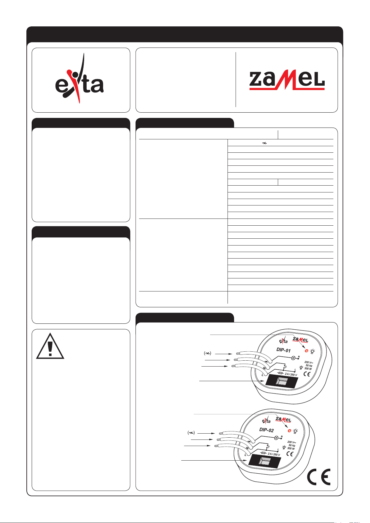
Load ON indicator
Load power lead
Trigger lead (IN)
Power lead (L)
Fuse socket
Load ON indicator
Load power lead
Trigger lead (IN)
Power lead (L)
Fuse socket
n
w
o
r
b
d
e
r
k
c
a
l
b
n
w
o
r
b
d
e
r
k
c
a
l
b

ASSEMBLY, OPERATION
1. Disconnect the electric network by
means of an appropriate cut-off,
current-limiting circuit-breaker or
separator.
2. Check if there is no any voltage
between power leads by means of
an appropriate gauge.
3. Mount the DIP-0X device in the 60
mm junction box.
4. Connect wires accordingly to the
electrical diagram.
5. Connect power supply circuit.
The device is capable of controlling
the light of up to 350 W. It is possible to
adjust the light level by means of a single
pole push button. If needed, it is possible
to connect the push buttons in parallel
and control the lights from various places. Short-pressing of the button (approximately 0.8 s) switches the light ON
/ OFF alternately. When the light is OFF,
short-pressing of the button switches
the light ON with maximum brightness or
switches the light OFF completely from
any brightness level. Holding the push
button for a long time (>0.8 s) allows alternate uent brightening up / dimming.
Only the DIP-02 model is capable of storing the light intensity level.
CONNECTIONS
n
w
o
r
b
d
e
r
k
c
a
l
b
n
w
o
r
b
d
e
r
k
c
a
l
b
CASING DIMENSIONS
PRODUCT FAMILY
The DIP-01, DIP-02 are member of the
DIX products family.
Device version:
01 - series,
basic
02 - series with
intensity storage
10 - basic
DIM-10 only
Casing type:
M - double-module
P - for junction box
Device type
UNIT DIAGRAM
LOAD
TIME DIAGRAMS
brightening up / dimming
μC
ON / OFF
WARRANTY
The product warranty is for a period of 24 months
Dealer signature & stamp, purchase date
1. ZMIE ZAMEL SP. J. assures 24 months guarantee for the product.
2. The manufacturer’s guarantee does not cover any of the following actions:
a) mechanical damage during transport, loading / unloading or under other circumstances,
b) damage caused by incorrect product mounting or misuse,
c) damage caused by unauthorised modications made by the PURCHASER or any third parties to the product or any other devices
needed for the product functioning,
d) damage caused by Act of God or any other incidents independent of the manufacturer.
3. The PURCHASER shall lay any claims in writing to the dealer or ZMIE ZAMEL SP. J.
4. ZMIE ZAMEL SP. J. is liable for processing any claim according to current Polish legislation.
5. ZMIE ZAMEL SP. J. shall process the claim at its own discretion: product repair, replacement or money return.
6. The manufacturer’s guarantee is valid in the Republic of Poland.
7. The PURCHASER’s statutory rights in any applicable legislation whether against the retailer arising from the purchase contract or
otherwise are not affected by this warranty.
 Loading...