

Page 1
OPERATIONS MANUAL
4010-3
ba76143e03 08/2013
MultiLab 4010-3
DIGITAL METER FOR IDS SENSORS
Page 2

MultiLab 4010-3
For the most recent version of the manual, please visit www.ysi.com.
Contact YSI
1725 Brannum Lane
Yellow Springs, OH 45387 USA
Tel: +1 937-767-7241
800-765-4974
Email: environmental@ysi.com
Internet: www.ysi.com
Copyright © 2013 Xylem Inc.
2 ba76143e03 08/2013
Page 3

MultiLab 4010-3 Contents
MultiLab 4010-3 - Contents
1 Overview. . . . . . . . . . . . . . . . . . . . . . . . . . . . . . . . . . . . . . . . . . 7
1.1 Meter MultiLab 4010-3 . . . . . . . . . . . . . . . . . . . . . . . . . . . . . . . . 7
1.2 Sensors. . . . . . . . . . . . . . . . . . . . . . . . . . . . . . . . . . . . . . . . . . . . 8
1.2.1 IDS sensors . . . . . . . . . . . . . . . . . . . . . . . . . . . . . . . . . . . . 8
1.2.2 IDS adapter for analog sensors . . . . . . . . . . . . . . . . . . . . . 9
1.2.3 Automatic sensor recognition . . . . . . . . . . . . . . . . . . . . . . 9
2 Safety . . . . . . . . . . . . . . . . . . . . . . . . . . . . . . . . . . . . . . . . . . . 10
2.1 Safety information . . . . . . . . . . . . . . . . . . . . . . . . . . . . . . . . . . . 10
2.1.1 Safety information in the operating manual . . . . . . . . . . . 10
2.1.2 Safety signs on the meter . . . . . . . . . . . . . . . . . . . . . . . . 10
2.1.3 Further documents providing safety information . . . . . . . 10
2.2 Safe operation. . . . . . . . . . . . . . . . . . . . . . . . . . . . . . . . . . . . . . 10
2.2.1 Authorized use. . . . . . . . . . . . . . . . . . . . . . . . . . . . . . . . . 10
2.2.2 Requirements for safe operation . . . . . . . . . . . . . . . . . . . 11
2.2.3 Unauthorized use. . . . . . . . . . . . . . . . . . . . . . . . . . . . . . . 11
3 Commissioning . . . . . . . . . . . . . . . . . . . . . . . . . . . . . . . . . . . 12
3.1 Scope of delivery . . . . . . . . . . . . . . . . . . . . . . . . . . . . . . . . . . . 12
3.2 Power supply . . . . . . . . . . . . . . . . . . . . . . . . . . . . . . . . . . . . . . 12
3.3 Initial commissioning . . . . . . . . . . . . . . . . . . . . . . . . . . . . . . . . . 12
3.3.1 Connecting the power pack . . . . . . . . . . . . . . . . . . . . . . . 13
4 Operation . . . . . . . . . . . . . . . . . . . . . . . . . . . . . . . . . . . . . . . . 14
4.1 General operating principles . . . . . . . . . . . . . . . . . . . . . . . . . . . 14
4.1.1 Keypad. . . . . . . . . . . . . . . . . . . . . . . . . . . . . . . . . . . . . . . 14
4.1.2 Display . . . . . . . . . . . . . . . . . . . . . . . . . . . . . . . . . . . . . . . 15
4.1.3 Status information . . . . . . . . . . . . . . . . . . . . . . . . . . . . . . 15
4.1.4 Instrument connectors . . . . . . . . . . . . . . . . . . . . . . . . . . . 16
4.1.5 Channel display . . . . . . . . . . . . . . . . . . . . . . . . . . . . . . . . 17
4.1.6 Sensor info. . . . . . . . . . . . . . . . . . . . . . . . . . . . . . . . . . . . 17
4.1.7 Display of several sensors in the measuring mode . . 18
4.2 Switching on the meter . . . . . . . . . . . . . . . . . . . . . . . . . . . . . . . 19
4.3 Switching off the meter . . . . . . . . . . . . . . . . . . . . . . . . . . . . . . . 19
4.4 Login with user name . . . . . . . . . . . . . . . . . . . . . . . . . . . . . . . . 19
4.5 Navigation . . . . . . . . . . . . . . . . . . . . . . . . . . . . . . . . . . . . . . . . . 21
4.5.1 Operating modes . . . . . . . . . . . . . . . . . . . . . . . . . . . . . . . 21
4.5.2 Measured value display . . . . . . . . . . . . . . . . . . . . . . . . . . 21
4.5.3 Menus and dialogs. . . . . . . . . . . . . . . . . . . . . . . . . . . . . . 21
4.5.4 Example 1 on navigation: Setting the language . . . . . . . 23
4.5.5 Example 2 on navigation: Setting the date and time . . . . 25
ba76143e03 08/2013 3
Page 4

Contents MultiLab 4010-3
5 pH value. . . . . . . . . . . . . . . . . . . . . . . . . . . . . . . . . . . . . . . . . . 27
5.1 Measuring . . . . . . . . . . . . . . . . . . . . . . . . . . . . . . . . . . . . . . . . 27
5.1.1 Measuring the pH value . . . . . . . . . . . . . . . . . . . . . . . . . 27
5.1.2 Measuring the temperature . . . . . . . . . . . . . . . . . . . . . . 28
5.2 pH calibration . . . . . . . . . . . . . . . . . . . . . . . . . . . . . . . . . . . . . . 29
5.2.1 Why calibrate? . . . . . . . . . . . . . . . . . . . . . . . . . . . . . . . . 29
5.2.2 When do you have to calibrate? . . . . . . . . . . . . . . . . . . . 29
5.2.3 Carrying out automatic calibration (AutoCal) . . . . 29
5.2.4 Carrying out a manual calibration (ConCal) . . . . . . . . . . 32
5.2.5 Calibration points . . . . . . . . . . . . . . . . . . . . . . . . . . . . . . 35
5.2.6 Calibration data . . . . . . . . . . . . . . . . . . . . . . . . . . . . . . . 36
5.2.7 Continuous measurement control (CMC function) . . 38
5.2.8 QSC function (sensor quality control) . . . . . . . . . . . . 40
6 ORP voltage . . . . . . . . . . . . . . . . . . . . . . . . . . . . . . . . . . . . . . 43
6.1 Measuring . . . . . . . . . . . . . . . . . . . . . . . . . . . . . . . . . . . . . . . . 43
6.1.1 Measuring the ORP . . . . . . . . . . . . . . . . . . . . . . . . . . . . 43
6.1.2 Measuring the relative ORP . . . . . . . . . . . . . . . . . . . . . . 44
6.1.3 Measuring the temperature . . . . . . . . . . . . . . . . . . . . . . 46
6.2 ORP calibration . . . . . . . . . . . . . . . . . . . . . . . . . . . . . . . . . . . . 46
7 Ion concentration . . . . . . . . . . . . . . . . . . . . . . . . . . . . . . . . . . 47
7.1 Measuring . . . . . . . . . . . . . . . . . . . . . . . . . . . . . . . . . . . . . . . . 47
7.1.1 Measuring the ion concentration . . . . . . . . . . . . . . . . . . 47
7.1.2 Measuring the temperature . . . . . . . . . . . . . . . . . . . . . . 49
7.2 Calibration . . . . . . . . . . . . . . . . . . . . . . . . . . . . . . . . . . . . . . . . 50
7.2.1 Why calibrate? . . . . . . . . . . . . . . . . . . . . . . . . . . . . . . . . 50
7.2.2 When to calibrate? . . . . . . . . . . . . . . . . . . . . . . . . . . . . . 50
7.2.3 Calibration (ISE Cal). . . . . . . . . . . . . . . . . . . . . . . . . . . . 50
7.2.4 Calibration standards . . . . . . . . . . . . . . . . . . . . . . . . . . . 53
7.2.5 Calibration data . . . . . . . . . . . . . . . . . . . . . . . . . . . . . . . 53
7.3 Selecting the measuring method . . . . . . . . . . . . . . . . . . . . . . . 56
7.3.1 Standard addition . . . . . . . . . . . . . . . . . . . . . . . . . . . . . . 57
7.3.2 Standard subtraction . . . . . . . . . . . . . . . . . . . . . . . . . . . 59
7.3.3 Sample addition . . . . . . . . . . . . . . . . . . . . . . . . . . . . . . . 62
7.3.4 Sample subtraction. . . . . . . . . . . . . . . . . . . . . . . . . . . . . 64
7.3.5 Standard addition with blank value correction (Blank value
addition) . . . . . . . . . . . . . . . . . . . . . . . . . . . . . . . . . 66
8 Dissolved oxygen (D.O.) . . . . . . . . . . . . . . . . . . . . . . . . . . . . 69
8.1 Measuring . . . . . . . . . . . . . . . . . . . . . . . . . . . . . . . . . . . . . . . . 69
8.1.1 Measuring D.O. . . . . . . . . . . . . . . . . . . . . . . . . . . . . . . . 69
8.1.2 Measuring the temperature . . . . . . . . . . . . . . . . . . . . . . 71
8.2 Calibration . . . . . . . . . . . . . . . . . . . . . . . . . . . . . . . . . . . . . . . . 71
8.2.1 Why calibrate? . . . . . . . . . . . . . . . . . . . . . . . . . . . . . . . . 71
8.2.2 When to calibrate? . . . . . . . . . . . . . . . . . . . . . . . . . . . . . 71
8.2.3 Calibration procedures . . . . . . . . . . . . . . . . . . . . . . . . . . 71
8.2.4 1-point calibration . . . . . . . . . . . . . . . . . . . . . . . . . . . . . . 72
8.2.5 2-point calibration . . . . . . . . . . . . . . . . . . . . . . . . . . . . . . 73
8.2.6 Calibration data . . . . . . . . . . . . . . . . . . . . . . . . . . . . . . . 75
4 ba76143e03 08/2013
Page 5

MultiLab 4010-3 Contents
9 Conductivity . . . . . . . . . . . . . . . . . . . . . . . . . . . . . . . . . . . . . . 78
9.1 Measuring . . . . . . . . . . . . . . . . . . . . . . . . . . . . . . . . . . . . . . . . 78
9.1.1 Measuring the conductivity. . . . . . . . . . . . . . . . . . . . . . . 78
9.1.2 Measuring the temperature . . . . . . . . . . . . . . . . . . . . . . 80
9.2 Temperature compensation. . . . . . . . . . . . . . . . . . . . . . . . . . . 80
9.3 Calibration . . . . . . . . . . . . . . . . . . . . . . . . . . . . . . . . . . . . . . . . 81
9.3.1 Why calibrate? . . . . . . . . . . . . . . . . . . . . . . . . . . . . . . . . 81
9.3.2 When to calibrate? . . . . . . . . . . . . . . . . . . . . . . . . . . . . . 81
9.3.3 Determining the cell constant (calibration in control
standard) . . . . . . . . . . . . . . . . . . . . . . . . . . . . . . . . 81
9.3.4 Calibration data . . . . . . . . . . . . . . . . . . . . . . . . . . . . . . . 82
10 Settings . . . . . . . . . . . . . . . . . . . . . . . . . . . . . . . . . . . . . . . . . . 84
10.1 pH measurement settings . . . . . . . . . . . . . . . . . . . . . . . . . . . . 84
10.1.1 Settings for pH measurements . . . . . . . . . . . . . . . . . . . . 84
10.1.2 Buffer sets for calibration . . . . . . . . . . . . . . . . . . . . . . . . 86
10.1.3 Calibration interval . . . . . . . . . . . . . . . . . . . . . . . . . . . . . 88
10.2 ORP measurement settings. . . . . . . . . . . . . . . . . . . . . . . . . . . 89
10.3 ISE measurement settings. . . . . . . . . . . . . . . . . . . . . . . . . . . . 89
10.4 D.O. measurement settings . . . . . . . . . . . . . . . . . . . . . . . . . . . 92
10.4.1 Settings for D.O. measurement . . . . . . . . . . . . . . . . . . . 92
10.4.2 Enter Sensor Cap coefficients . . . . . . . . . . . . . . . . . . . . 92
10.4.3 Saturation local. . . . . . . . . . . . . . . . . . . . . . . . . . . . . . . . 92
10.5 Cond measurement settings . . . . . . . . . . . . . . . . . . . . . . . . . . 92
10.5.1 Settings for IDS conductivity sensors . . . . . . . . . . . . . . . 92
10.6 Sensor-independent settings . . . . . . . . . . . . . . . . . . . . . . . . . . 96
10.6.1 System . . . . . . . . . . . . . . . . . . . . . . . . . . . . . . . . . . . . . . 96
10.6.2 Data storage. . . . . . . . . . . . . . . . . . . . . . . . . . . . . . . . . . 97
10.6.3 Automatic Stability control . . . . . . . . . . . . . . . . . . . . . . . 97
10.7 Reset . . . . . . . . . . . . . . . . . . . . . . . . . . . . . . . . . . . . . . . . . . . . 98
10.7.1 Resetting the measurement settings . . . . . . . . . . . . . . . 98
10.7.2 Resetting the system settings. . . . . . . . . . . . . . . . . . . . 101
11 Data storage . . . . . . . . . . . . . . . . . . . . . . . . . . . . . . . . . . . . . 102
11.1 Manual data storage . . . . . . . . . . . . . . . . . . . . . . . . . . . . . . . 102
11.2 Automatic data storage at intervals . . . . . . . . . . . . . . . . . 102
11.3 Measurement data storage . . . . . . . . . . . . . . . . . . . . . . . . . . 105
11.3.1 Editing the measurement data storage. . . . . . . . . . . . . 105
11.3.2 Erasing the measurement data storage . . . . . . . . . . . . 106
11.3.3 Measurement dataset . . . . . . . . . . . . . . . . . . . . . . . . . . 106
11.3.4 Storage locations . . . . . . . . . . . . . . . . . . . . . . . . . . . . . 107
12 Transmitting data . . . . . . . . . . . . . . . . . . . . . . . . . . . . . . . . . 108
12.1 Outputting current measurement data . . . . . . . . . . . . . . . . . . 108
12.2 Transmitting data . . . . . . . . . . . . . . . . . . . . . . . . . . . . . . . . . . 108
12.3 Connecting the PC / USB-B interface (USB Device) . . . . 108
12.4 Connecting a USB memory device/USB printer
(USB-A interface (USB Host)) . . . . . . . . . . . . . . . . . . . . . . . . 109
12.5 Options for data transmission to the USB-B (PC)
interface and the USB-A (USB printer) interface . . . . . . . . . . 110
12.6 Data transmission to the USB-A interface
ba76143e03 08/2013 5
Page 6

Contents MultiLab 4010-3
(USB memory device) . . . . . . . . . . . . . . . . . . . . . . . . . . . . . . 111
12.7 MultiLab Importer. . . . . . . . . . . . . . . . . . . . . . . . . . . . . . . . . . 111
12.8 BOD Analyst Pro . . . . . . . . . . . . . . . . . . . . . . . . . . . . . . . . . . 111
13 Maintenance, cleaning, disposal. . . . . . . . . . . . . . . . . . . . . 112
13.1 Maintenance . . . . . . . . . . . . . . . . . . . . . . . . . . . . . . . . . . . . . 112
13.1.1 General maintenance activities . . . . . . . . . . . . . . . . . . 112
13.1.2 Exchanging the battery. . . . . . . . . . . . . . . . . . . . . . . . . 112
13.2 Cleaning. . . . . . . . . . . . . . . . . . . . . . . . . . . . . . . . . . . . . . . . . 113
13.3 Packing . . . . . . . . . . . . . . . . . . . . . . . . . . . . . . . . . . . . . . . . . 113
13.4 Disposal . . . . . . . . . . . . . . . . . . . . . . . . . . . . . . . . . . . . . . . . . 113
14 What to do if.... . . . . . . . . . . . . . . . . . . . . . . . . . . . . . . . . . . . 115
14.1 pH . . . . . . . . . . . . . . . . . . . . . . . . . . . . . . . . . . . . . . . . . . . . . 115
14.2 ISE . . . . . . . . . . . . . . . . . . . . . . . . . . . . . . . . . . . . . . . . . . . . . 117
14.3 Dissolved oxygen. . . . . . . . . . . . . . . . . . . . . . . . . . . . . . . . . . 118
14.4 Conductivity . . . . . . . . . . . . . . . . . . . . . . . . . . . . . . . . . . . . . . 118
14.5 General information . . . . . . . . . . . . . . . . . . . . . . . . . . . . . . . . 119
15 Technical data. . . . . . . . . . . . . . . . . . . . . . . . . . . . . . . . . . . . 121
15.1 Measuring ranges, resolution, accuracy . . . . . . . . . . . . . . . . 121
15.2 General data . . . . . . . . . . . . . . . . . . . . . . . . . . . . . . . . . . . . . 121
16 Firmware update. . . . . . . . . . . . . . . . . . . . . . . . . . . . . . . . . . 126
16.1 Firmware update for the meter MultiLab 4010-3 . . . . . . . . . . 126
16.2 Firmware-Update for IDS Sensors. . . . . . . . . . . . . . . . . . . . . 127
17 Glossary . . . . . . . . . . . . . . . . . . . . . . . . . . . . . . . . . . . . . . . . 128
18 Index . . . . . . . . . . . . . . . . . . . . . . . . . . . . . . . . . . . . . . . . . . . 131
19 Appendix . . . . . . . . . . . . . . . . . . . . . . . . . . . . . . . . . . . . . . . . 134
19.1 Oxygen solubility table. . . . . . . . . . . . . . . . . . . . . . . . . . . . . . 134
19.2 DO% Calibration values. . . . . . . . . . . . . . . . . . . . . . . . . . . . . 136
20 Contact Information . . . . . . . . . . . . . . . . . . . . . . . . . . . . . . . 137
20.1 Ordering & Technical Support . . . . . . . . . . . . . . . . . . . . . . . . 137
20.2 Service Information . . . . . . . . . . . . . . . . . . . . . . . . . . . . . . . . 137
6 ba76143e03 08/2013
Page 7
MultiLab 4010-3 Overview
1
2
3
4010-3
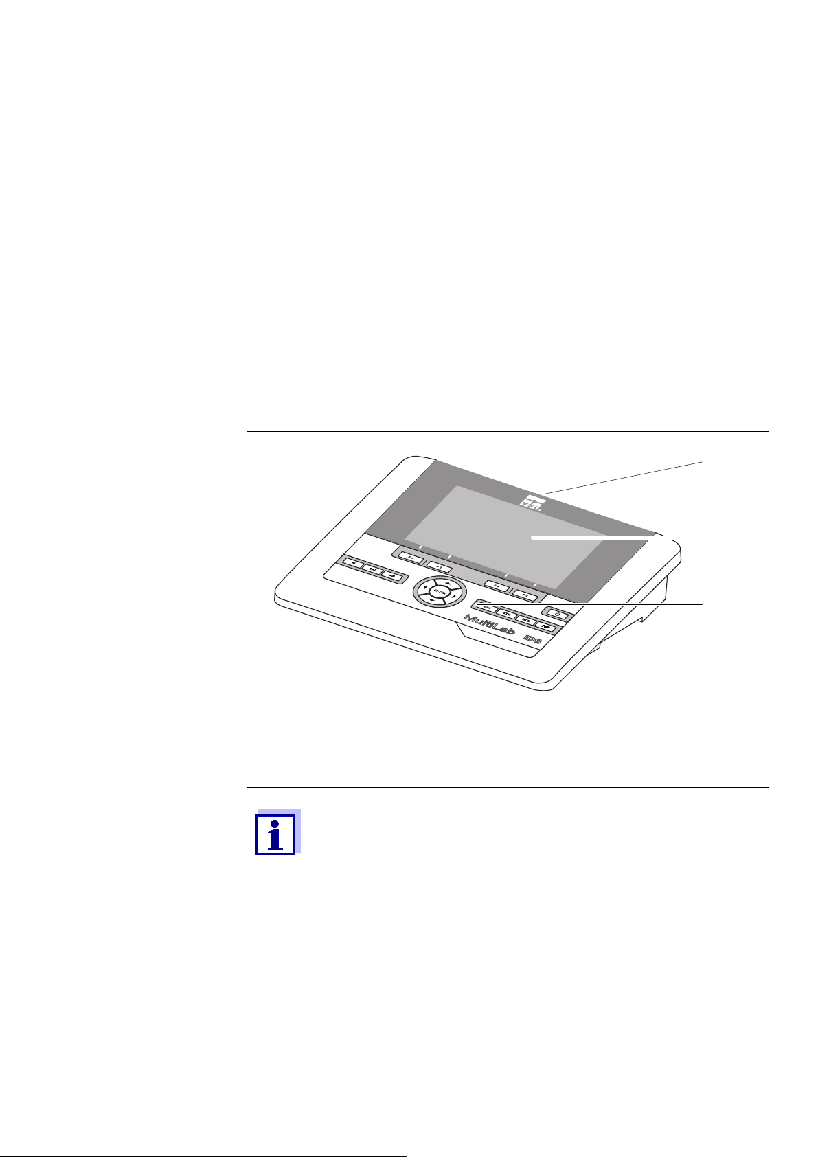
1 Overview
1.1 Meter MultiLab 4010-3
The MultiLab 4010-3 meter enables you to perform measurements (pH, U, ISE,
conductivity, D.O.) quickly and reliably.
The MultiLab 4010-3 provides the maximum degree of operating comfort, reliability and measuring certainty for all applications.
The MultiLab 4010-3 supports you in your work with the following functions:
proven calibration procedures
automatic stability control (AR),
automatic sensor recognition
CMC (continuous measurement control)
QSC (sensor quality control).
1 Keypad (antibacterial)
2Display
3 Connectors
Due to its antibacterial properties, the keypad of the
MultiLab 4010-3 is especially suitable for applications in an environment where hygiene is important (see
DATA, page 121).
SECTION 15.2 GENERAL
ba76143e03 08/2013 7
Page 8

Overview MultiLab 4010-3
1.2 Sensors
1.2.1 IDS sensors
IDS sensors
support the automatic sensor recognition
show only the settings relevant to the specific sensor in the setting menu
process signals in the sensor digitally so that precise and interference-free
measurements are enabled even with long cables
facilitate to assign a sensor to a measured parameter with differently colored
couplings
have quick-lock couplings with which to fix the sensors to the meter.
Sensor data from
IDS sensors
IDS sensors transmit the following sensor data to the meter:
SENSOR ID
– Sensor name
– Sensor series number
Calibration data
Measurement settings
The calibration data are updated in the IDS sensor after each calibration procedure. A message is displayed while the data are being updated in the sensor.
In the measured value display, you can display the sensor name
and series number of the selected sensor with the [Info] softkey.
You can then display further sensor data stored in the sensor with
the [More] softkey (see section 4.1.6 S
ENSOR INFO, page 17).
8 ba76143e03 08/2013
Page 9

MultiLab 4010-3 Overview
1.2.2 IDS adapter for analog sensors
With the aid of an IDS adapter, you can also operate analog sensors
on the MultiLab 4010-3. The combination of the IDS adapter and analog sensor
behaves like an IDS sensor.
The MultiLab 4010-3 has a recess where the IDS adapter (ADA 94/IDS DIN or
ADA 94/IDS BNC), which is available as an accessory, can be permanently
mounted.
The IDS adapter replaces a digital input (channel 2) with a connector for an
analog pH/ U/ISE sensor (DIN or BNC plug) and a temperature sensor.
1.2.3 Automatic sensor recognition
The automatic sensor recognition for IDS sensors allows
to operate an IDS sensor with different meters without recalibrating
to operate different IDS sensors at one meter without recalibration
to assign measurement data to an IDS sensor
– Measurement datasets are always stored and output with the sensor
name and sensor series number.
to assign calibration data to an IDS sensor
– Calibration data and calibration history are always stored and output with
the sensor name and sensor series number.
to activate the correct cell constant for conductivity sensors automatically
to hide menus automatically that do not concern this sensor
To be able to use the automatic sensor recognition, a meter that supports the
automatic sensor recognition (e.g. MultiLab 4010-3) and a digital IDS sensor
are required.
In digital IDS sensors, sensor data are stored that clearly identify the sensor.
The sensor data are automatically taken over by the meter.
ba76143e03 08/2013 9
Page 10
Safety MultiLab 4010-3
2Safety
2.1 Safety information
2.1.1 Safety information in the operating manual
This operating manual provides important information on the safe operation of
the meter. Read this operating manual thoroughly and make yourself familiar
with the meter before putting it into operation or working with it. The operating
manual must be kept in the vicinity of the meter so you can always find the information you need.
Important safety instructions are highlighted in this operating manual. They are
indicated by the warning symbol (triangle) in the left column. The signal word
(e.g. "Caution") indicates the level of danger:
WARNING
indicates a possibly dangerous situation that can lead to serious (irreversible) injury or death if the safety instruction is not
followed.
CAUTION
indicates a possibly dangerous situation that can lead to slight
(reversible) injury if the safety instruction is not followed.
NOTE
indicates a possibly dangerous situation where goods might be damaged
if the actions mentioned are not taken.
2.1.2 Safety signs on the meter
Note all labels, information signs and safety symbols on the meter. A warning
symbol (triangle) without text refers to safety information in this operating
manual.
2.1.3 Further documents providing safety information
The following documents provide additional information, which you should
observe for your safety when working with the measuring system:
• Operating manuals of sensors and other accessories
• Safety datasheets of calibration or maintenance accessories (such as buffer
solutions, electrolyte solutions, etc.)
2.2 Safe operation
2.2.1 Authorized use
The authorized use of the meter consists exclusively of the measurement of the
pH, ORP, conductivity and dissolved oxygen in a laboratory environment.
10 ba76143e03 08/2013
Page 11

MultiLab 4010-3 Safety
Only the operation and running of the meter according to the instructions and
technical specifications given in this operating manual is authorized (see
section 15 T
ECHNICAL DATA, page 121).
Any other use is considered unauthorized.
2.2.2 Requirements for safe operation
Note the following points for safe operation:
• The meter may only be operated according to the authorized use specified
above.
• The meter may only be supplied with power by the energy sources
mentioned in this operating manual.
• The meter may only be operated under the environmental conditions
mentioned in this operating manual.
• The meter may not be opened.
2.2.3 Unauthorized use
The meter must not be put into operation if:
• it is visibly damaged (e.g. after being transported)
• it was stored under adverse conditions for a lengthy period of time (storing
conditions, see section 15 T
ECHNICAL DATA, page 121).
ba76143e03 08/2013 11
Page 12

Commissioning MultiLab 4010-3
3 Commissioning
3.1 Scope of delivery
MeterMultiLab 4010-3
USB cable (A plug on mini B plug)
Power pack
Stand with stand base
Short instructions
Detailed operating manual
CD-ROM
3.2 Power supply
The MultiLab 4010-3 is supplied with power in the following ways:
Mains operation with the supplied power pack
Operation of the system clock with a buffer battery if there is no mains power
supply (see section 13.1.2 E
XCHANGING THE BATTERY, page 112).
3.3 Initial commissioning
Perform the following activities:
Connect the power pack
(see section 3.3.1 C
Switch on the meter
(see section 4.2 S
Set the date and time
(see section 4.5.5 E
page 25)
Mount the stand
(see operating manual of the stand)
ONNECTING THE POWER PACK, page 13)
WITCHING ON THE METER, page 19)
XAMPLE 2 ON NAVIGATION: SETTING THE DATE AND TIME,
12 ba76143e03 08/2013
Page 13
MultiLab 4010-3 Commissioning
3.3.1 Connecting the power pack
CAUTION
The line voltage at the operating site must lie within the input
voltage range of the original power pack (see section 15.2
G
ENERAL DATA, page 121).
CAUTION
Use original power packs only (see section 15.2 GENERAL DATA,
page 121).
1. Connect the plug of the power pack to the socket for the power pack on
the MultiLab 4010-3.
2. Connect the original power pack to an easily accessible power outlet.
The meter performs a self-test.
ba76143e03 08/2013 13
Page 14
Operation MultiLab 4010-3
4 Operation
4.1 General operating principles
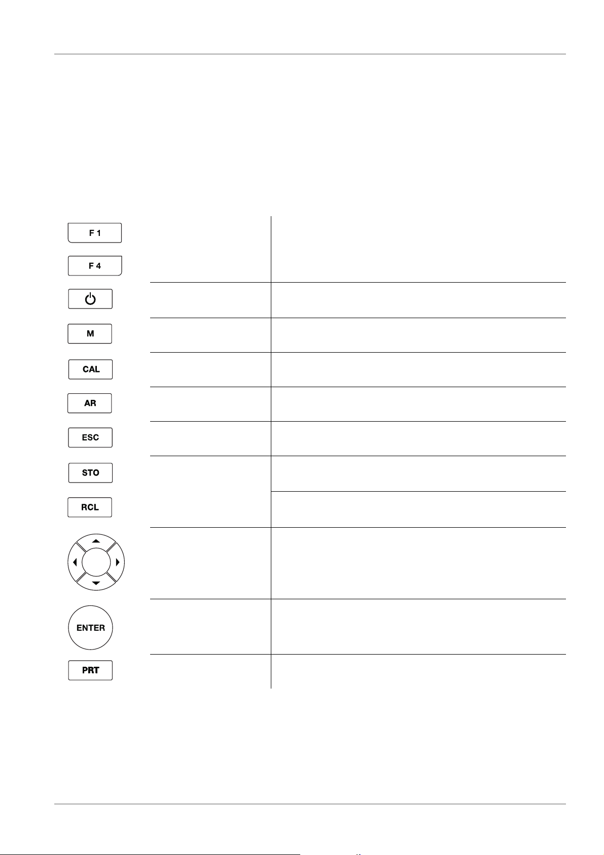
4.1.1 Keypad
In this operating manual, keys are indicated by brackets <..> .
The key symbol (e.g. <ENTER>) generally indicates a short keystroke (press
and release) in this operating manual. A long keystroke (hold for approx. 2 sec)
is indicated by the underscore behind the key symbol (e.g. <ENTER_>).
<F1>
<F4>
<On/Off> Switches the meter on or off
<M> Selects the measured parameter
<CAL>
<CAL_>
<AR> Freezes the measured value (HOLD function)
<ESC> Switches back to the higher menu level /
<STO>
<STO_>
<RCL>
<RCL_>
Softkeys providing situation dependent functions, e.g.:
<F1>/[Info]: View information on a sensor
Calls up the calibration procedure
Displays the calibration data
Switches the AutoRead measurement on or off
Cancels inputs
Saves a measured value manually
Opens the menu for the automatic save function
Displays the manually stored measured values
Displays the automatically stored measured values
<><>
<><>
<ENTER>
<ENTER_>
<PRT>
<PRT_>
14 ba76143e03 08/2013
Menu control, navigation
Opens the menu for measurement settings / Confirms
entries
Opens the menu for system settings
Outputs stored data to the interface
Outputs displayed data to the interface at intervals
Page 15
MultiLab 4010-3 Operation
4
3
2
5
7
8
9
6
1
HOLD AR
AutoCal TEC
01.08.2013 08:00Info
YSI
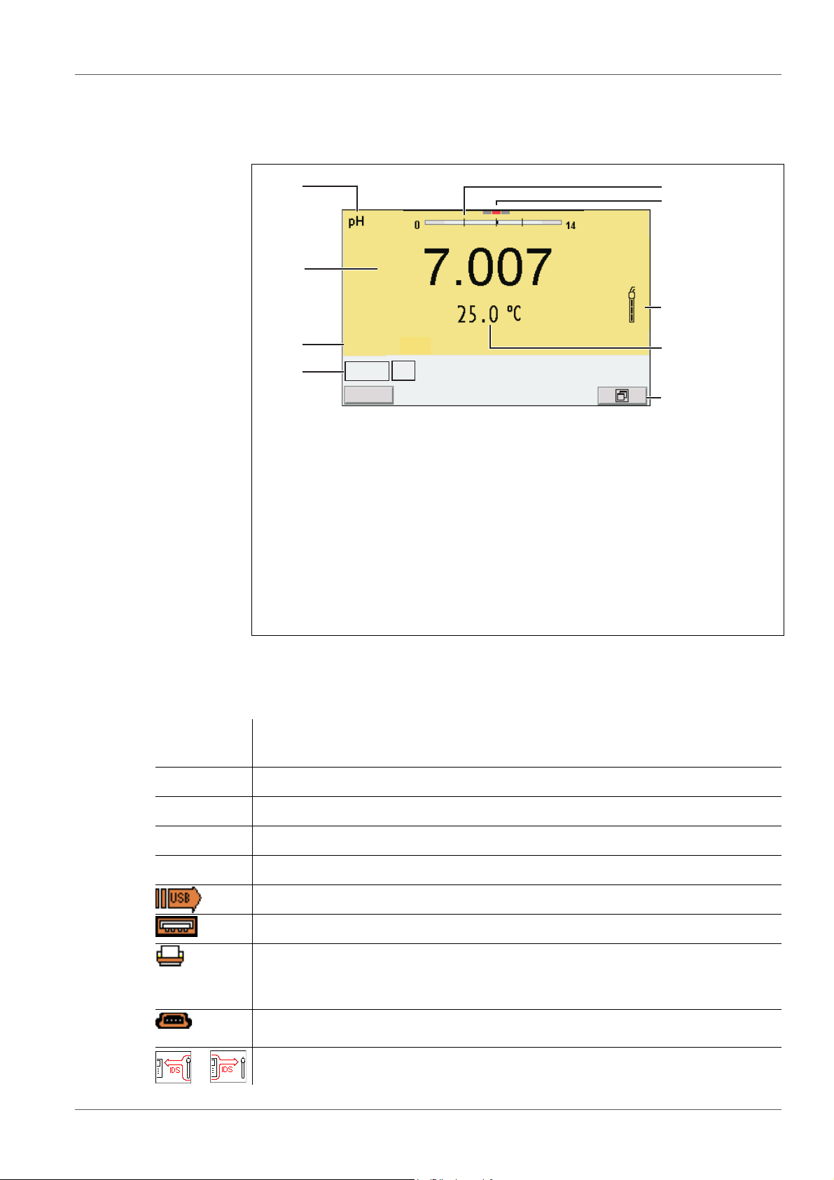
4.1.2 Display
Example (pH):
1 Status information (meter)
2 Status information (sensor)
3 Measured value
4 Measured parameter
5 Continuous measurement control (CMC function)
6 Channel display: Plug position of the sensor
7 Sensor symbol (calibration evaluation, calibration interval)
8 Measured temperature (with unit)
9 Softkeys and date + time
4.1.3 Status information
AutoCal
e.g. YSI
ConCal Calibration with any buffers
Error An error occurred during calibration
AR Stability control (AutoRead) is active
HOLD Measured value is frozen (<AR> key)
Calibration with automatic buffer recognition, e.g. with the buffer set: YSI buffers
Data are automatically output to the USB-B interface at intervals
Data are output to the USB-A interface (USB flash drive)
Data are output to the USB-A interface (USB printer). If there is a USB-B
connection at the same time (e.g. to a PC), the data are output to the USBB interface only.
Connection to a PC is active (USB-B interface)
Data transfer from/to a IDS sensor is active
ba76143e03 08/2013 15
Page 16
Operation MultiLab 4010-3
746
3 51
bac
2
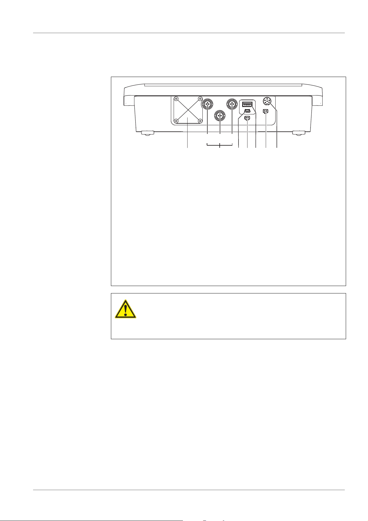
4.1.4 Instrument connectors
1 IDS sensors: (pH, ORP, conductivity, D.O.)
a) Channel 1
b) Channel 2
c) Channel 3
2 USB B (device) interface
3 Stirrer (ProOBOD)
4 USB-A (host) interface
5 Power pack
6 Service interface
7 Cover plate
The cover plate closes the mounting slot for the IDS adapter (4010-2/
3 pH Adapter DIN or 4010-2/3 pH Adapter BNC) available as an
accessory
CAUTION
Only connect sensors to the meter that cannot return any voltages or currents that are not allowed (> SELV and > current circuit with current limiting).
YSI IDS sensors and IDS adapters meet these requirements.
16 ba76143e03 08/2013
Page 17
MultiLab 4010-3 Operation
1
01.08.2013 08:00
Info
01.08.2013 08:00Info
4.1.5 Channel display
The MultiLab 4010-3 manages the connected sensors and displays which sensor is plugged to which connection.
1 Channel display: Display of the plug position for the respective
parameter
The red bar indicates for each connected sensor to which plug position (channel) of the meter it is connected.
4.1.6 Sensor info
You can display the current sensor data and sensor settings of a connected
sensor at any time. The sensor data are available in the measured value display with the /[Info] softkey.
1. In the measured value display:
Display the sensor data (sensor name, series number) with [Info].
ba76143e03 08/2013 17
Page 18
Operation MultiLab 4010-3
01.08.2013 08:00
More
4110
B092500013
01.08.2013 08:00
Man. temperature: 25 °C
pH resolution 0.001
mV resolution 0.1
Buffer YSI
Calibration interval 7d
Unit for slope mV/pH
QSC: off
Software version 1.00
4110
B092500013
01.08.2013 08:00Info
760 mmHg
01.08.2013 08:00Info
2. Display further sensor data (settings) with [More].
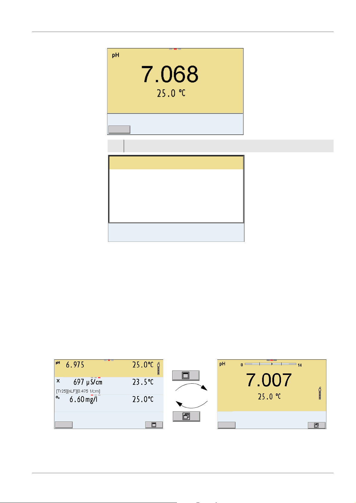
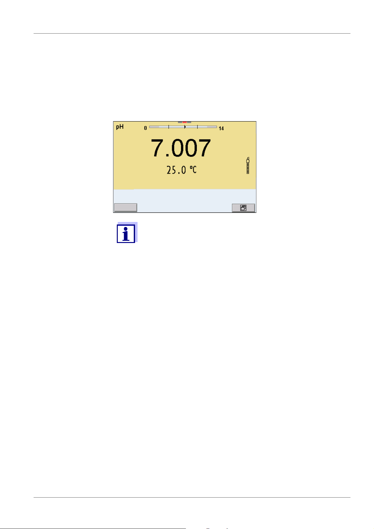
4.1.7 Display of several sensors in the measuring mode
The measured values of the connected sensors can be displayed in the following ways:
Clear display of all connected sensors
Detailed display of one sensor
(e.g. incl. CMC feature with pH sensors)
With the softkey you can very easily switch between the two display types. The
suitable softkey is displayed depending on the operating situation.
18 ba76143e03 08/2013
Page 19
MultiLab 4010-3 Operation
01.08.2013 08:00
Info
4.2 Switching on the meter
1. Switch the meter on with <On/Off>.
The meter performs a self-test.
2. Connect the sensor.
The meter is ready to measure.
If the user administration function is activated, the Login dialog
appears after the meter is switched on (see section 4.4 L
USER NAME, page 19).
OGIN WITH
The user administration function is not active in the delivery condition.
4.3 Switching off the meter
1. Switch off the meter with <On/Off>.
4.4 Login with user name
After activation of the user administration (see the MultiLab User operating
manual) by the administrator, measurements
are only possible after login with a user name. The user name is documented
with the measured values and in records.
All user names entered by the administrator are listed in the User name menu.
The administrator determines for each user whether or not a password is
required for the login to the meter.
If the Password menu item is grayed out, no password is required for the login.
1. Switch on the meter with <On/Off>.
The Login dialog appears.
ba76143e03 08/2013 19
Page 20
Operation MultiLab 4010-3
User name Admin
Password ####
Change password
Login
01.08.2013 08:00
2. Using <><>, select the menu item, User name and confirm with
<ENTER>.
The user name is highlighted.
3. Using <><>, select a user name and confirm with <ENTER>.
The login is done immediately if no password is required.
If a sensor is connected the measured value display appears.
4. If a password is required:
Using <><>, select the menu item, Password and confirm with
<ENTER>.
The user specifies the password when he or she first logs in with a
user name.
A valid password consists of 4 digits.
The user can change the password with the next login.
5. Change the digit of the highlighted position with <><>.
Switch to the next position of the password with <><>.
When the password was completely entered, confirm with <ENTER>.
The login takes place. If a sensor is connected the measured value display appears.
Changing the
If the administrator has set up the access with password protection:
password
1. Switch on the meter with <On/Off>.
2. Using <><>, select the menu item, User name and confirm with
3. Using <><>, select a user name and confirm with <ENTER>.
4. Using <><>, select the menu item, Change password and confirm
20 ba76143e03 08/2013
The Login dialog appears.
<ENTER>.
The user name is highlighted.
with <ENTER>.
Page 21
MultiLab 4010-3 Operation
5. In the Password field, enter the old password with <><> and
<><>and confirm it with <ENTER>.
6. In the New password field, enter the new password with <><> and
<><>and confirm it with <ENTER>.
The password is changed.
The login takes place. If a sensor is connected the measured value display appears.
Forgotten the
password?
Contact the administrator.
4.5 Navigation
4.5.1 Operating modes
Operating
mode
Measuring The measurement data of the connected sensor are shown
Calibration The course of a calibration with calibration information, func-
Storage in
memory
Transmittin
g data
Setting The system menu or a sensor menu with submenus, set-
Explanation
in the measured value display
tions and settings is displayed
The meter stores measuring data automatically or manually
The meter transmits measuring data and calibration records
to a USB interface automatically or manually.
tings and functions is displayed
4.5.2 Measured value display
In the measured value display, you can
use <><> to select one of several connected sensors. The selected
sensor is displayed with a colored background.
The following actions / menus refer to the selected sensor
open the menu for calibration and measurement settings with <ENTER>
(short
keystroke)
open the Storage & config menu with the sensor-independent settings by
pressing <ENTER_> (long
keystroke, approx. 2 s).
change the display in the selected measuring screen (e. g. pH <−> mV) by
pressing <M>.
4.5.3 Menus and dialogs
The menus for settings and dialogs in procedures contain further subelements.
ba76143e03 08/2013 21
Page 22
Operation MultiLab 4010-3
General
Interface
Clock function
Service information
Reset
System
01.08.2013 08:00
Language: English
Audio signal: on
Brightness: 12
Temperature unit: °C
Stability control: on
General
01.08.2013 08:00
pH
01.08.2013 08:00
Calibration record
Calibration data storage
Buffer: YSI
Single-point calibration: yes
Calibration interval: 7 d
Unit for slope: mV/pH
[
i
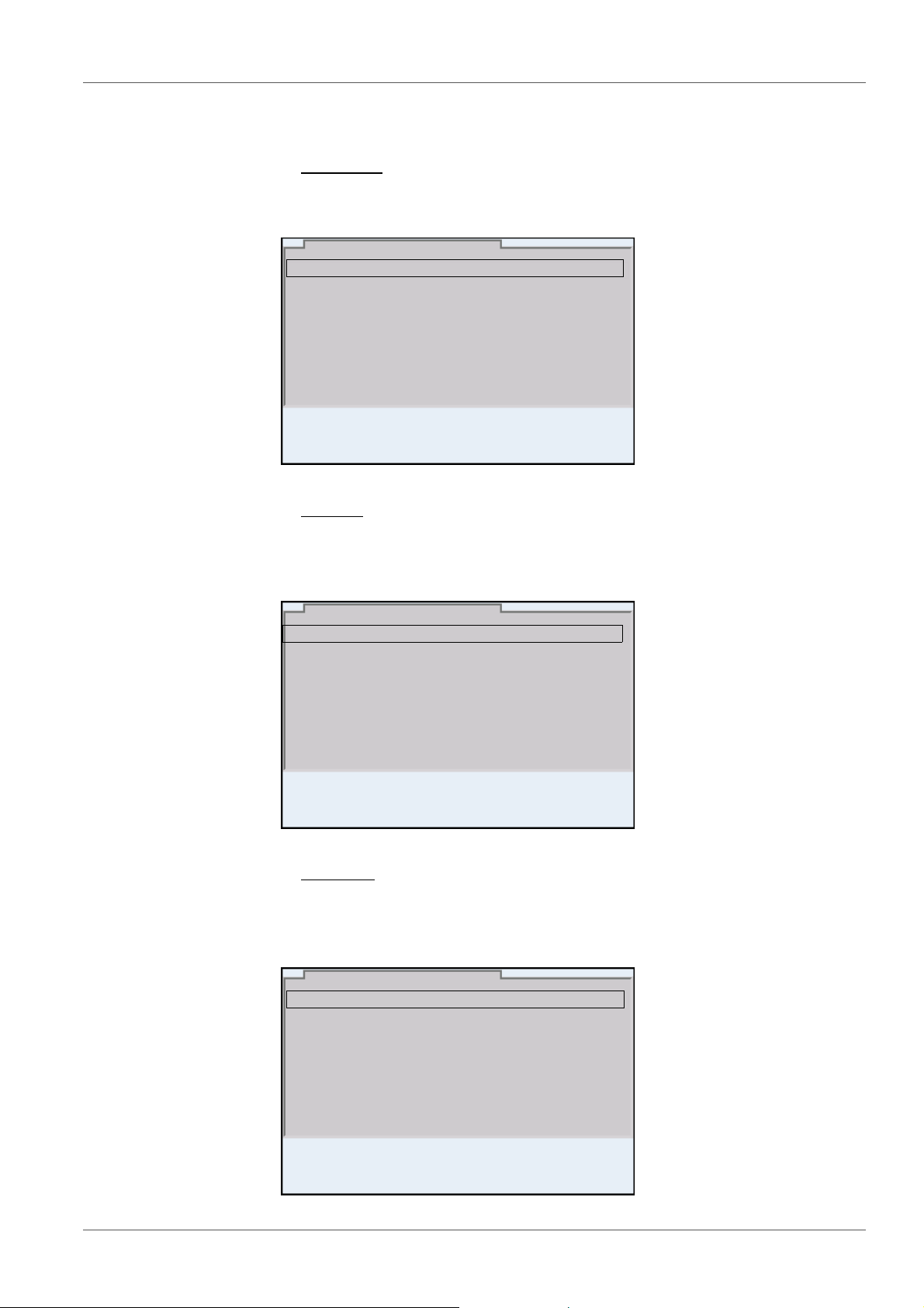
] 2.00 4.00 7.00 10.00
The selection is made with the <><> keys. The current selection is displayed with a frame.
Submenus
The name of the submenu is displayed at the upper edge of the frame. Submenus are opened by confirming with <ENTER>. Example:
Settings
Settings are indicated by a colon. The current setting is displayed on the
right-hand side. The setting mode is opened with <ENTER>. Subsequently,
the setting can be changed with <><> and <ENTER>. Example:
Functions
Functions are designated by the name of the function. They are immediately
carried out by confirming with <ENTER>. Example: Display the Calibration
record function.
22 ba76143e03 08/2013
Page 23
MultiLab 4010-3 Operation
Calibration record
Calibration data storage
Buffer: YSI
Single-point calibration: yes
Calibration interval: 7 d
Unit for slope: mV/pH
[i] 2.00 4.00 7.00 10.00
pH
01.08.2013 08:00
01.08.2013 08:00
Info
System
Data storage
Storage & config
01.08.2013 08:00
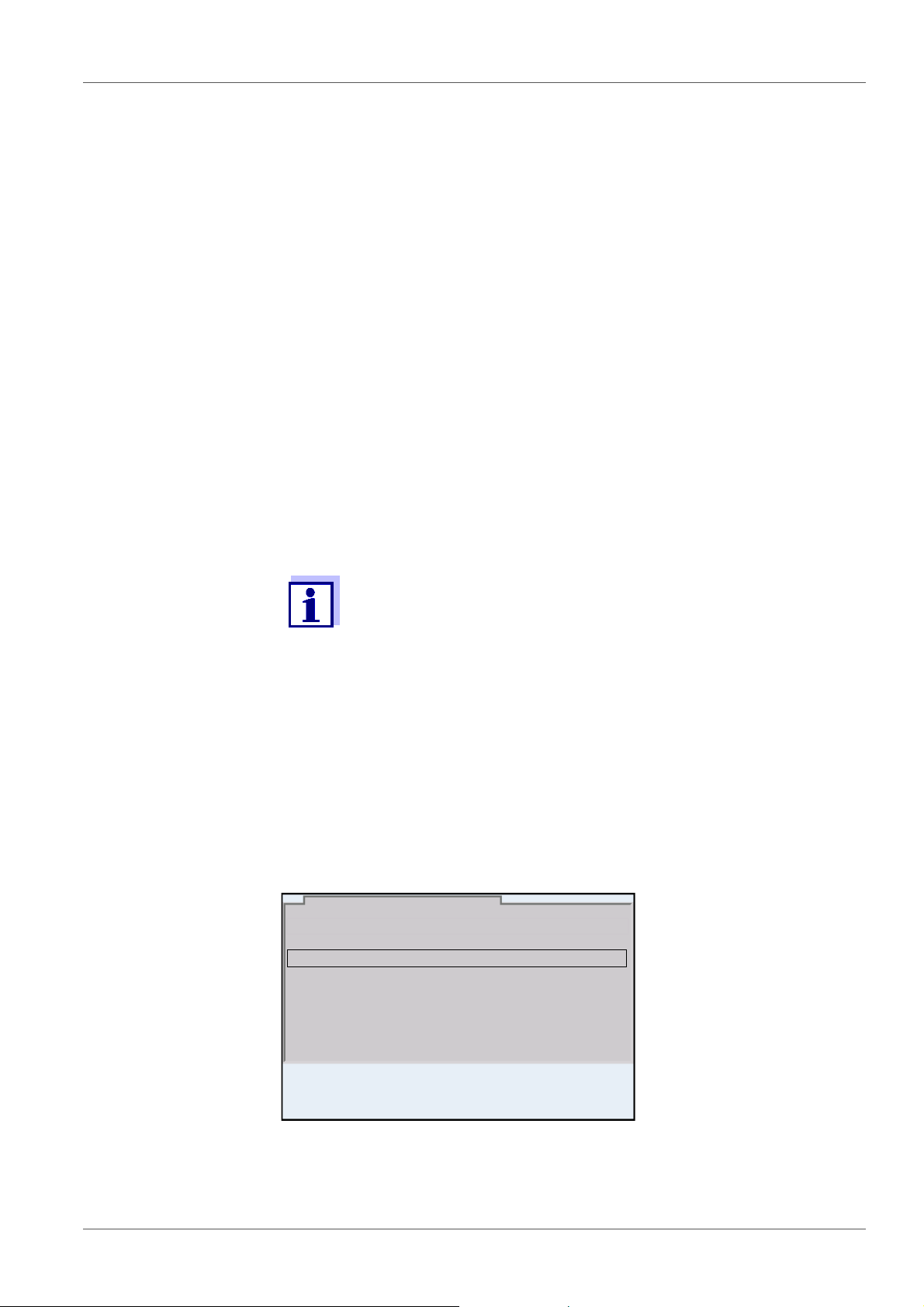
Messages
Information is marked by the [
i
] symbol. It cannot be selected. Example:
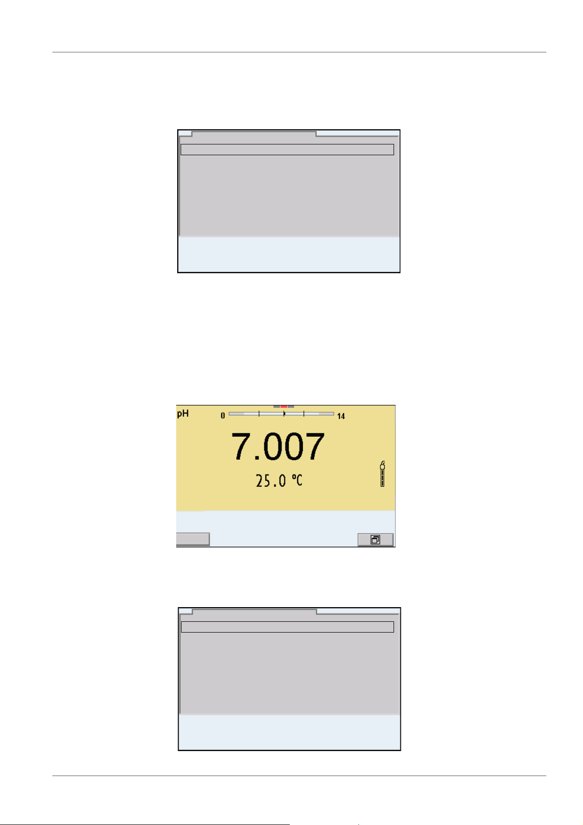
4.5.4 Example 1 on navigation: Setting the language
1. Press the <On/Off> key.
The measured value display appears.
The instrument is in the measuring mode.
2. Open the Storage & config menu with <ENTER_>.
The instrument is in the setting mode.
ba76143e03 08/2013 23
Page 24
Operation MultiLab 4010-3
General
Interface
Clock function
Service information
Reset
System
01.08.2013 08:00
Language: English
Audio signal: on
Brightness: 12
Temperature unit: °C
Stability control: on
General
01.08.2013 08:00
Language: English
Audio signal: on
Brightness: 12
Temperature unit: °C
Stability control: on
General
01.08.2013 08:00
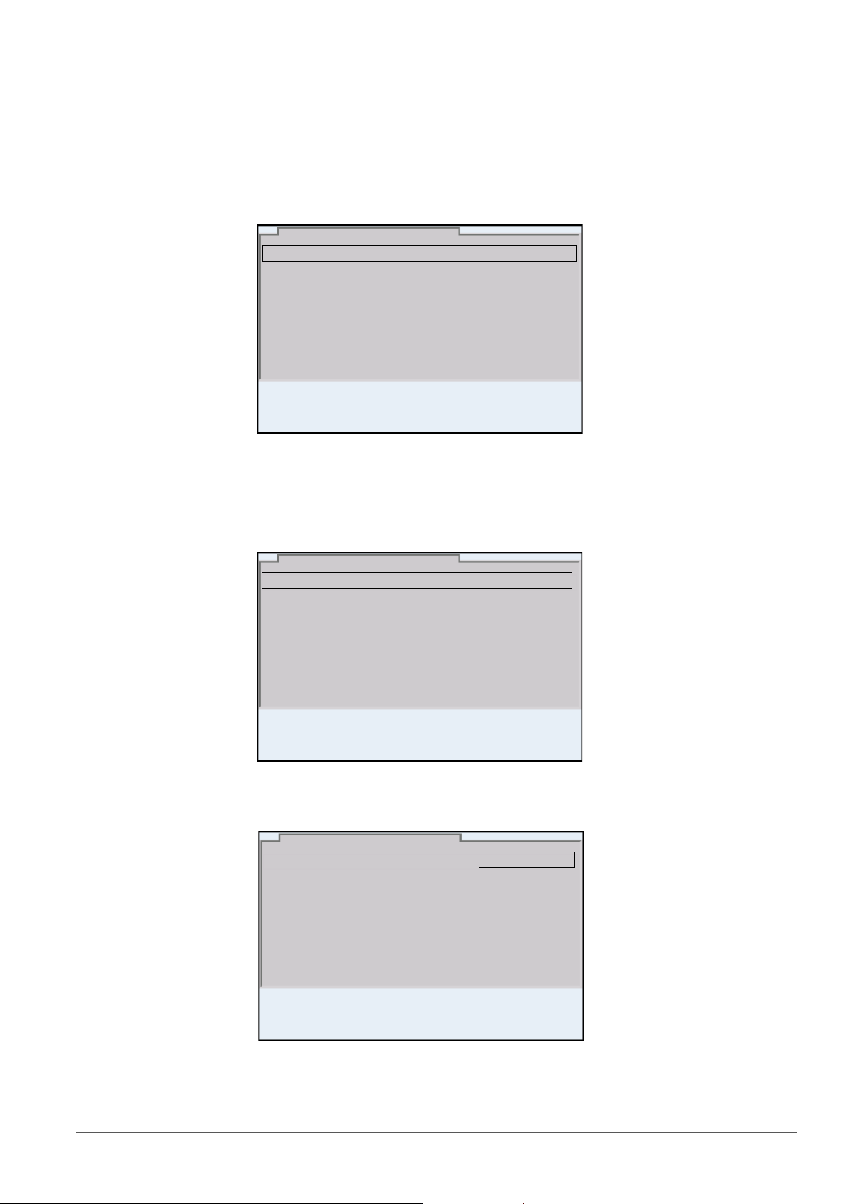
3. Select the System submenu with <><>.
The current selection is displayed with a frame.
4. Open the System submenu with <ENTER>.
5. Select the General submenu with <><>.
The current selection is displayed with a frame.
6. Open the General
submenu with <ENTER>.
7. Open the setting mode for the Language with <ENTER>.
24 ba76143e03 08/2013
8. Select the required language with <><>.
Page 25
MultiLab 4010-3 Operation
Date format: dd.mm.yy
Date: 03.04.2013
Time: 14:53:40
Clock function
01.08.2013 08:00
9. Confirm the setting with <ENTER>.
The meter switches to the measuring mode.
The selected language is active.
4.5.5 Example 2 on navigation: Setting the date and time
The meter has a clock with a date function. The date and time are indicated in
the status line of the measured value display.
When storing measured values and calibrating, the current date and time are
automatically stored as well.
The correct setting of the date and time and date format is important for the following functions and displays:
Current date and time
Calibration date
Identification of stored measured values.
Setting the date,
time and date format
Therefore, check the time at regular intervals.
The date and time are reset (to 01.01.2012 00:00 hours), if the following conditions are met:
the supply voltage failed and
the buffer batteries for the system clock are empty.
The date format can be switched from the display of day, month, year
(dd.mm.yy) to the display of month, day, year (mm/dd/yy or mm.dd.yy).
1. In the measured value display:
Open the Storage & config menu with <ENTER_>.
The instrument is in the setting mode.
2. Select and confirm the System / Clock function menu with <><>
and <ENTER>.
The setting menu for the date and time opens up.
ba76143e03 08/2013 25
3. Select and confirm the Time menu with <><> and <ENTER>.
The hours are highlighted.
Page 26

Operation MultiLab 4010-3
4. Change and confirm the setting with <><> and <ENTER>.
The minutes are highlighted.
5. Change and confirm the setting with <><> and <ENTER>.
The seconds are highlighted.
6. Change and confirm the setting with <><> and <ENTER>.
The time is set.
7. If necessary, set the Date and Date format. The setting is made simi-
larly to that of the time.
8. To make further settings, switch to the next higher menu level with
<ESC>.
or
Switch to the measured value display with <M>.
The instrument is in the measuring mode.
26 ba76143e03 08/2013
Page 27
MultiLab 4010-3 pH value
01.08.2013 08:00Info
5 pH value
5.1 Measuring
5.1.1 Measuring the pH value
The sensor connection and the USB-B (device) interface are galvanically isolated. This facilitates interference-free measurements
also in the following cases:
Measurement in grounded test samples
Measurement with several sensors connected to one
MultiLab 4010-3 in one test sample
1. Connect the IDS pH sensor to the meter.
The pH measuring window is displayed.
2. If necessary, select the measured parameter with <M>.
Stability control
(AutoRead)
& HOLD function
3. Adjust the temperature of the solutions and measure the current tem-
perature if the measurement is made without a temperature sensor.
4. If necessary, calibrate or check the IDS pH sensor.
5. Immerse the IDS pH sensor in the test sample.
The stability control function (AutoRead) continually checks the stability of the
measurement signal. The stability has a considerable impact on the reproducibility of measured values.
The measured parameter flashes on the display
as soon as the measured value is outside the stability range
when the automatic Stability control is switched off.
You can start the Stability control manually at any time, irrespective of the set-
ting for automatic Stability control (see section 10.6.3 A
CONTROL, page 97) in the System menu.
UTOMATIC STABILITY
1. Freeze the measured value with <AR>.
The [HOLD] status indicator is displayed.
The HOLD function is active.
ba76143e03 08/2013 27
Page 28
pH value MultiLab 4010-3
You can terminate the Stability control function and the HOLD function with <AR> or <M> at any time.
2. Using <ENTER>, activate the Stability control function manually.
The [AR] status indicator appears while the measured value is assessed
as not stable. A progress bar is displayed and the display of the measured parameter flashes.
As soon as a measured value meets the stability criteria, it is frozen. The
[HOLD][AR] status indicator is displayed, the progress bar disappears
and the display of the measured parameter stops flashing.
The current measurement data is output to the interface. Measurement
data meeting the stability control criterion is marked by AR.
You can prematurely terminate the Stability control function manually with <ENTER> at any time. When the Stability control function
is prematurely terminated, the current measurement data are output to the interface (PC, USB memory device or USB printer) without AutoRead info.
Criteria for a stable
measured value
3. Using <ENTER>, start a further measurement with stability control.
or
Release the frozen measured value again with <AR> or <M>.
The [AR] status display disappears. The display switches back to the previous indication.
The Stability control function checks whether the measured values are stable
within the monitored time interval.
Measured
Time interval Stability in the time interval
parameter
pH value 15 seconds
Temperature 15 seconds
Δ : Better than 0.01 pH
Δ : Better than 0.5 °C
The minimum duration until a measured value is assessed as stable is the
monitored time interval. The actual duration is mostly longer.
5.1.2 Measuring the temperature
For reproducible pH measurements, it is essential to measure the temperature
of the test sample.
IDS sensors measure the temperature with a temperature sensor integrated in
the IDS sensor.
When operating a sensor without integrated temperature sensor, e.g.
via an IDS pH adapter, you have to measure and enter the temperature of the
test sample first.
28 ba76143e03 08/2013
Page 29

MultiLab 4010-3 pH value
The display of the temperature indicates the active temperature measuring
mode:
Temperature
sensor
Resolution of the
temp. display
Temp. measurement
Yes 0.1 °C Automatic with temperature
sensor
- 1 °C Manual
5.2 pH calibration
5.2.1 Why calibrate?
pH electrodes age. This changes the zero point (asymmetry) and slope of the
pH electrode. As a result, an inexact measured value is displayed. Calibration
determines and stores the current values of the zero point and slope of the
electrode.
Thus, you should calibrate at regular intervals.
5.2.2 When do you have to calibrate?
Routinely within the framework of the company quality assurance
When the calibration interval has expired
5.2.3 Carrying out automatic calibration (AutoCal)
Make sure that in the sensor menu, Buffer menu, the buffer set is correctly
selected (see section 10.1.1 S
ETTINGS FOR PH MEASUREMENTS, page 84).
Use one to five buffer solutions of the selected buffer set in any order.
Below, calibration with YSI buffers (YSI) is described. When other buffer sets
are used, other nominal buffer values are displayed. Apart from that, the procedure is identical.
If single-point calibration was set in the menu, the calibration procedure is automatically finished with the measurement of buffer solution 1 and the calibration record is displayed.
1. Connect the pH sensor to the meter.
The pH measuring window is displayed.
2. Keep the buffer solutions ready.
When measuring without temperature sensor:
Temper the buffer solutions or measure the current temperature.
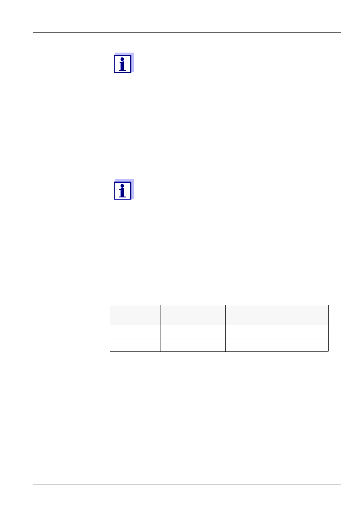
3. Start the calibration with <CAL>.
The calibration display for the first buffer appears (voltage display).
ba76143e03 08/2013 29
Page 30
pH value MultiLab 4010-3
01.08.2013 08:00
YSI
01.08.2013 08:00
YSI
10.000
4. Thoroughly rinse the sensor with deionized water.
5. Immerse the sensor in the first buffer solution.
6. For measurements without temperature sensor
(e.g. when using an IDS adapter
):
Enter the temperature of the buffer with <><>.
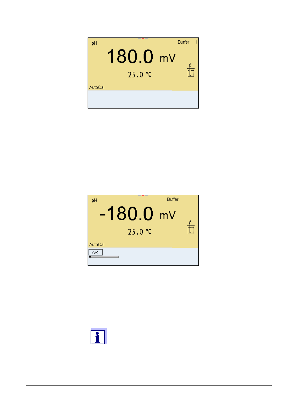
7. Start the measurement with <ENTER>.
The measured value is checked for stability (stability control).
The [AR] status indicator is displayed. The measured parameter
flashes.
8. Wait for the end of the measurement with stability control or accept the
calibration value with <ENTER>.
The calibration display for the next buffer appears (voltage display).
9. If necessary, finish the calibration procedure as a single-point calibration
with <M>.
The calibration record is displayed.
For single-point calibration, the instrument uses the Nernst slope
(-59.2 mV/pH at 25 °C) and determines the zero point of the IDS pH
sensor.
Continuing with two-
point calibration
10. Thoroughly rinse the sensor with deionized water.
11. Immerse the pH sensor in buffer solution 2.
30 ba76143e03 08/2013
Page 31

MultiLab 4010-3 pH value
01.08.2013 08:00
YSI
12. When measuring without temperature sensor:
Enter the temperature of the buffer with <><>.
13. Start the measurement with <ENTER>.
The measured value is checked for stability (stability control).
The [AR] status indicator is displayed. The measured parameter
flashes.
Continuing with
three- to five-point
calibration
14. Wait for the measurement with stability control to be completed or termi-
nate the stability control and take over the calibration value with
<ENTER>.
The calibration display for the next buffer appears (voltage display).
15. If necessary, finish the calibration procedure as a two-point calibration
with <M>.
The calibration record is displayed.
16. Thoroughly rinse the sensor with deionized water.
17. Immerse the sensor in the next buffer solution.
18. When measuring without temperature sensor:
Enter the temperature of the buffer with <><>.
19. Start the measurement with <ENTER>.
The measured value is checked for stability (stability control).
The [AR] status indicator is displayed. The measured parameter
flashes.
ba76143e03 08/2013 31
Page 32

pH value MultiLab 4010-3
01.08.2013 08:00
YSI
4.000
20. Wait for the measurement with stability control to be completed or termi-
nate the stability control and take over the calibration value with
<ENTER>.
The calibration display for the next buffer appears (voltage display).
21. If necessary, use <M> to finish the calibration.
The calibration record is displayed.
or
Switch to calibration with the next buffer with <ENTER>.
Calibration is automatically completed after the last buffer of a buffer set has been measured. Then the calibration record is displayed.
The calibration line is determined by linear regression.
5.2.4 Carrying out a manual calibration (ConCal)
Make sure that in the sensor menu, Buffer menu, the ConCal buffer set is
correctly selected (see section 10.1.1 S
ETTINGS FOR PH MEASUREMENTS, page
84).
Use any one to five buffer solutions in ascending or descending order.
If single-point calibration was set in the menu, the calibration procedure is automatically finished with the measurement of buffer solution 1 and the calibration record is displayed.
1. Connect the pH sensor to the meter.
The pH measuring window is displayed.
2. Keep the buffer solutions ready.
When measuring without temperature sensor:
Temper the buffer solutions or measure the current temperature.
3. Start the calibration with <CAL>.
The calibration display for the first buffer appears (voltage display).
32 ba76143e03 08/2013
Page 33

MultiLab 4010-3 pH value
01.08.2013 08:00
01.08.2013 08:00
01.08.2013 08:00
4. Thoroughly rinse the sensor with deionized water.
5. Immerse the pH sensor in buffer solution 1.
6. For measurements without temperature sensor
(e.g. when using an IDS adapter
):
Enter the temperature of the buffer with <><>.
7. Start the measurement with <ENTER>.
The measured value is checked for stability (stability control).
The [AR] status indicator is displayed. The measured parameter flashes.
8. Wait for the measurement with stability control to be completed or ter-
minate the stability control and take over the calibration value with
<ENTER>.
The pH value of the buffer solution is displayed.
ba76143e03 08/2013 33
Page 34

pH value MultiLab 4010-3
01.08.2013 08:00
9. Set the nominal buffer value for the measured temperature with
<><>.
10. Accept the calibration value with <ENTER>.
The calibration display for the next buffer appears (voltage display).
11. If necessary, finish the calibration procedure as a single-point calibration
with <M>.
The calibration record is displayed.
For single-point calibration, the instrument uses the Nernst slope
(-59.2 mV/pH at 25 °C) and determines the zero point of the IDS pH
sensor.
Continuing with two-
point calibration
12. Thoroughly rinse the sensor with deionized water.
13. Immerse the pH sensor in buffer solution 2.
14. When measuring without temperature sensor:
Enter the temperature of the buffer with <><>.
15. Start the measurement with <ENTER>.
The measured value is checked for stability (stability control).
The [AR] status indicator is displayed. The measured parameter
flashes.
16. Wait for the measurement with stability control to be completed or ter-
minate the stability control and take over the calibration value with
<ENTER>.
The pH value of the buffer solution is displayed.
17. Set the nominal buffer value for the measured temperature with
<><>.
18. Accept the calibration value with <ENTER>.
The calibration display for the next buffer appears (voltage display).
19. If necessary, finish the calibration procedure as a two-point calibration
with <M>.
The calibration record is displayed.
34 ba76143e03 08/2013
Page 35

MultiLab 4010-3 pH value
01.08.2013 08:00
Continuing with
three- to five-point
calibration
20. Thoroughly rinse the sensor with deionized water.
21. Immerse the sensor in the next buffer solution.
22. When measuring without temperature sensor:
Enter the temperature of the buffer with <><>.
23. Start the measurement with <ENTER>.
The measured value is checked for stability (stability control).
The [AR] status indicator is displayed. The measured parameter
flashes.
24. Wait for the measurement with stability control to be completed or ter-
minate the stability control and take over the calibration value with
<ENTER>.
The pH value of the buffer solution is displayed.
25. Set the nominal buffer value for the measured temperature with
<><>.
26. Accept the calibration value with <ENTER>.
The calibration display for the next buffer appears (voltage display).
27. If necessary, use <M> to finish the calibration.
The calibration record is displayed.
or
Continue calibrating using the next buffer with <ENTER>.
After the fifth buffer has been measured the calibration is automatically finished. Then the calibration record is displayed.
The calibration line is determined by linear regression.
5.2.5 Calibration points
Calibration can be performed using one to five buffer solutions in any order
(single-point to five-point calibration). The meter determines the following
values and calculates the calibration line as follows:
ba76143e03 08/2013 35
Page 36

pH value MultiLab 4010-3
Calibration Determined val-
Displayed calibration data
ues
1-point Asy Zero point = Asy
Slope = Nernst slope
(-59.2 mV/pH at 25 °C)
2-point Asy
Slp.
3-point to 5point
Asy
Slp.
Zero point = Asy
Slope = Slp.
Zero point = Asy
Slope = Slp.
The calibration line is calculated by
linear regression.
You can display the slope in the units, mV/pH or % (see section
10.1.1 S
ETTINGS FOR PH MEASUREMENTS, page 84).
5.2.6 Calibration data
Displaying the cali-
bration data
The calibration record is automatically transmitted to the interface
after calibrating.
The calibration record of the last calibration is to be found under the menu item,
Calibration / Calibration record. To open it in the measured value display, press
the <CAL_> key.
The calibration records of the last 10 calibrations are to be found in the menu,
Calibration / Calibration data storage / Display. To open the Calibration menu,
press the <ENTER> key in the measured value display.
36 ba76143e03 08/2013
Page 37

MultiLab 4010-3 pH value
Menu item Setting/
function
Calibration /
- Displays the calibration records.
Calibration data storage /Display
Calibration / Calibra-
- Outputs the stored calibration data to
tion data storage /
Output to USB flash
drive or printer
Explanation
Further options:
Scroll through the calibration
records with <><>.
Using <PRT>, output the dis-
played calibration record to the
USB-B (PC) interface or the USBA (USB printer) interface.
Using <PRT_>, output all calibra-
tion records to the USB-B (PC)
interface or the USB-A (USB
printer) interface.
Quit the display with <ESC>.
Switch directly to the measured
value display with <M>.
the USB-A interface (USB memory
device/USB printer)
Calibration evalua-
tion
Calibration /
Calibration data stor-
- Outputs the stored calibration data to
the USB-B interface (PC)
age /
Output to RS232/USB
After calibrating, the meter automatically evaluates the calibration. The zero
point and slope are evaluated separately. The worse evaluation of both is taken
into account. The evaluation appears on the display and in the calibration
record.
Display Calibration
record
+++
++
Zero point
Slope [mV/pH]
[mV]
-15 ... +15 -60.5 ... -58.0
-20 ... <-15
>-58.0 ... -57.0
or
>+15 ... +20
+
-25 ... <-20
or
>+20 ... +25
-61.0 ... <-60.5
or
>-57.0 ... -56.0
-
ba76143e03 08/2013 37
-30 ... <-25
or
->+25 ... + 30
-62.0 ... <-61.0
or
>-56.0 ... -50.0
Page 38

pH value MultiLab 4010-3
CALIBRATION pH
03.04.2013 07:43:33
4110
Ser. no. B092500013
YSI
Buffer 1 4.00
Buffer 2 7.00
Buffer 3 10.00
Voltage 1 184.0 mV
Voltage 2 3.0 mV
Voltage 3 -177.0 mV
Temperature 1 24.0 °C
Temperature 2 24.0 °C
Temperature 3 24.0 °C
Slope -60.2 mV/pH
Asymmetry 4.0 mV
Sensor +++
etc...
Calibration record
Display Calibration
record
Clean the IDS sensor according
to the sensor operating manual
Error Error
Error elimination (see section 14
HAT TO DO IF..., page 115)
W
For pH IDS sensors you can optionally enable a more finely graded
calibration evaluation (QSC) (see section 5.2.8 QSC
(
SENSOR QUALITY CONTROL), page 40).
Zero point
[mV]
<-30
or
>+30
Slope [mV/pH]
<-62.0
or
> -50,0
FUNCTION
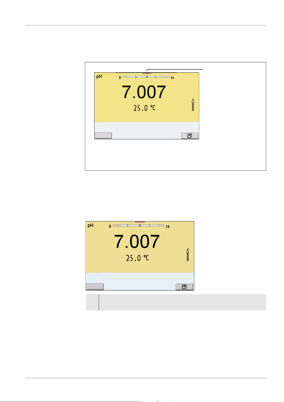
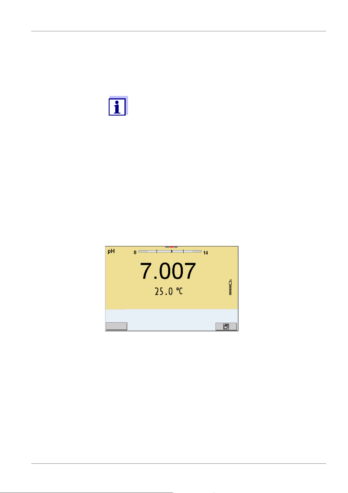
5.2.7 Continuous measurement control (CMC function)
The Continuous Measurement Control (CMC function) facilitates to evaluate
the current measured value instantly and definitely.
After each successful calibration the scale of the pH measuring range is
displayed in the measured value display. Here you can very clearly see
38 ba76143e03 08/2013
whether or not the current measured value is in the calibrated part of the
measuring range.
Page 39

MultiLab 4010-3 pH value
1
2
3
4
01.08.2013 08:00
Info
The following information is displayed:
1 Currently measured pH value (needle)
2 Marking lines for all nominal buffer values used with the last valid cali-
bration
3 Measuring range for which a valid calibration is available. Measured
values in this range are suitable for documentation.
4 Measuring range for which no valid calibration is available (dark
gray). Measured values in this range are not suitable for documentation. Calibrate the meter with buffers covering this measuring range.
If the current measured value is outside the calibrated range, this area
is displayed in a darker gray.
If a measured value is outside the measuring range pH 0 - 14, overflow arrows are displayed at the left or right edge of the measuring
range.
The limits of the calibrated range are determined by the buffers used for calibration:
Lower limit: Buffer with lowest pH value - 2 pH units
Upper limit: Buffer with highest pH value + 2 pH units
ba76143e03 08/2013 39
Page 40

pH value MultiLab 4010-3
01.08.2013 08:00
Info
1
5.2.8 QSC function (sensor quality control)
General information
on the QSC function
The QSC function (Quality Sensor Control) is a new sensor evaluation for
digital IDS sensors. It evaluates the condition of an IDS pH sensor individually
and with a very fine grading.
The QSC scale shows the current sensor evaluation with an indicator on the
display.
1 QSC scale
The double arrow on the QSC scale indicates the current sensor evaluation
In the USB output the sensor evaluation is given as a percentage (1-100).
The finely graded sensor evaluation of the QSC function promptly calls your
attention to changes of the sensor.
Thus you can do what is necessary to restore the optimum measuring quality
(e.g. clean, calibrate or replace the sensor).
Sensor evaluation
with / without
QSC function
With QSC function Without QSC function (sensor sym-
bol)
Very fine grading of the sensor evaluation (100 grades)
The reference value is individually
determined for each sensor during
Rough grading of the sensor evaluation (4 grades)
A theoretical reference value is used
for all sensors
the QSC initial calibration.
Low tolerances for zero point and
slope when using QSC buffer solutions
Additional QSC calibration required
Greater tolerances for zero point and
slope when using commercial buffer
sets
No additional calibration required
(with special QSC buffer set)
QSC calibration The QSC function is enabled by once carrying out an additional three-point cali-
bration with special QSC buffer solutions. It covers the measuring range of the
sensor (pH 2 to pH 11). The QSC initial calibration determines the actual condition of the sensor and stores it as a reference in the sensor.
To meet the high requirements of a QSC initial calibration, the QSC initial calibration should optimally be carried out with the initial commissioning of the
sensor.
40 ba76143e03 08/2013
Page 41

MultiLab 4010-3 pH value
01.08.2013 08:00
Carry out the normal calibrations for your special measuring range with your
usual standard solutions as previously done.
As soon as the QSC function was enabled for an IDS sensor, it is
not possible to return to the sensor evaluation with the sensor
symbol for this sensor.
Carrying out a QSC
initial calibration
1. Open the menu for measurement settings with <ENTER>.
2. In the QSC menu, select First calibration with <><>.
The calibration display appears. AutoCal QSC-Kit is displayed as the
buffer.
Exclusively use the QSC-Kit for the QSC calibration. If you use other
buffers, you will have no valid QSC calibration.
3. Calibration with the buffers of the QSC-Kit is done like a normal threepoint calibration.
Follow the user guide.
Carry out the QSC initial calibration very carefully. It determines the
reference value for the sensor. This reference value cannot be
overwritten or reset.
As soon as the QSC function was enabled, it is not possible to
return to the sensor evaluation with the sensor symbol.
4. As soon as the three-point calibration has been successfully carried out
you can decide whether to accept or discard the calibration as the QSC
initial calibration.
The QSC initial calibration is completed. The sensor is calibrated. If you want
to calibrate with special buffers for your measurements, you can subsequently
carry out a normal calibration with your buffers. The reference values determined with the QSC calibration are also used for the evaluation of normal calibrations. In the measured value display, the QSC scale of the QSC function is
always displayed. A double arrow on the QSC scale indicates the current sen-
ba76143e03 08/2013 41
Page 42

pH value MultiLab 4010-3
01.08.2013 08:00
Info
1
sor evaluation.
1 QSC scale
The double arrow on the QSC scale indicates the current sensor evaluation
Carrying out a QSC
control calibration
A QSC control calibration can, e.g. be useful if the sensor evaluation noticeably
changed (after some normal calibrations).
You can carry out QSC control calibrations at greater intervals than normal calibrations.
1. Open the menu for measurement settings with <ENTER>.
2. In the QSC menu, select Control calibration with <><>.
The calibration display appears. AutoCal QSC-Kit is displayed as the buffer.
Exclusively use the QSC-Kit for the QSC calibration. If you use other buffers, you will have no valid QSC control calibration.
3. Follow the user guide.
The calibration is carried out like a normal three-point calibration. As soon
as the three-point calibration has been successfully carried out you can
decide whether to accept or discard the calibration as the QSC control
calibration.
42 ba76143e03 08/2013
Page 43

MultiLab 4010-3 ORP voltage
01.08.2013 08:00
Info
6 ORP voltage
6.1 Measuring
6.1.1 Measuring the ORP
The sensor connection and the USB-B (device) interface are galvanically isolated. This facilitates interference-free measurements
also in the following cases:
Measurement in grounded test samples
Measurement with several sensors connected to one
MultiLab 4010-3 in one test sample
IDS ORP sensors are not calibrated. However, you can check IDS
ORP sensors using a test solution.
Stability control
(AutoRead)
& HOLD function
1. Connect the ORP sensor to the meter.
The ORP measuring window is displayed.
2. Adjust the temperature of the solutions and measure the current temperature if the measurement is made without a temperature sensor.
3. Check the meter with the ORP sensor.
4. Immerse the ORP sensor in the test sample.
The stability control function (AutoRead) continually checks the stability of the
measurement signal. The stability has a considerable impact on the reproducibility of measured values.
The measured parameter flashes on the display
as soon as the measured value is outside the stability range
when the automatic Stability control is switched off.
You can start the Stability control manually at any time, irrespective of the
setting for automatic Stability control (see section 10.6.3 A
CONTROL, page 97) in the System menu.
ba76143e03 08/2013 43
UTOMATIC STABILITY
Page 44

ORP voltage MultiLab 4010-3
1. Freeze the measured value with <AR>.
The [HOLD] status indicator is displayed.
The HOLD function is active.
You can terminate the Stability control function and the HOLD function with <AR> or <M> at any time.
2. Using <ENTER>, activate the Stability control function manually.
The [AR] status indicator appears while the measured value is assessed
as not stable. A progress bar is displayed and the display of the measured parameter flashes.
As soon as a measured value meets the stability criteria, it is frozen. The
[HOLD][AR] status indicator is displayed, the progress bar disappears
and the display of the measured parameter stops flashing.
The current measurement data is output to the interface. Measurement
data meeting the stability control criterion is marked by AR.
Criteria for a stable
measured value
You can prematurely terminate the Stability control function manu-
ally with <ENTER> at any time. When the Stability control function
is prematurely terminated, the current measurement data are output to the interface (PC, USB memory device or USB printer) without AutoRead info.
3. Using <ENTER>, start a further measurement with stability control.
or
Release the frozen measured value again with <AR> or <M>.
The [AR] status display disappears. The display switches back to the previous indication.
The Stability control function checks whether the measured values are stable
within the monitored time interval.
Measured
parameter
ORP 15 seconds
Temperature 15 seconds
Time interval Stability in the time
interval
Δ : Better than 0.3 mV
Δ : Better than 0.5 °C
The minimum duration until a measured value is assessed as stable is the
monitored time interval. The actual duration is mostly longer.
6.1.2 Measuring the relative ORP
To measure the difference of the ORPs of two solutions, you have to define the
ORP of one solution as the zero point first.
44 ba76143e03 08/2013
Page 45

MultiLab 4010-3 ORP voltage
01.08.2013 08:00
Info
ORP electrodes can be used to determine the relative ORP.
1. Connect the ORP electrode to the meter.
2. Prepare the reference solution for the determination of the reference
point.
3. Select the ΔU (mV display with <M>.
4. Immerse the ORP electrode in the reference solution.
5. Display the potential of the current zero point with <CAL>.
6. Press <ENTER> to measure the reference solution.
The measured value is checked for stability (automatic stability control). The display of the measured parameter flashes.
The measured potential is defined as the zero point.
or
Press <M> to terminate the display of the zero point.
7. Rinse the ORP electrode and immerse it in the test sample.
The measured value is checked for stability (automatic stability control). The display of the measured parameter flashes.
8. Wait for a stable measured value.
The display of the measured parameter no longer flashes.
AutoRead The Stability control function checks whether the measured values are stable
within the monitored time interval.
Measured parame-
Time interval Stability in the time interval
ter
ORP 15 seconds
Temperature 15 seconds
Δ : better than 0.3 mV
Δ : better than 0.5 °C
The minimum duration until a measured value is assessed as stable is the
monitored time interval. The actual duration is mostly longer.
ba76143e03 08/2013 45
Page 46

ORP voltage MultiLab 4010-3
6.1.3 Measuring the temperature
For reproducible ORP measurements, it is essential to measure the temperature of the test sample.
When operating a sensor without integrated temperature sensor, you first have
to measure and enter the temperature of the sample.
The measuring instrument recognizes whether a suitable sensor is connected
and automatically switches on the temperature measurement.
The display of the temperature indicates the active temperature measuring
mode:
Temperature
sensor
Resolution of
the temp. dis-
Temp. measurement
play
Yes 0.1 °C Automatic with temperature sensor
- 1 °C Manual
6.2 ORP calibration
ORP electrodes are not calibrated. You can, however, check ORP
electrodes by measuring the ORP of a test solution and comparing
the value with the nominal value.
46 ba76143e03 08/2013
Page 47

MultiLab 4010-3 Ion concentration
7 Ion concentration
7.1 Measuring
7.1.1 Measuring the ion concentration
The sensor connection and the USB-B (device) interface are galvanically isolated. This facilitates interference-free measurements
also in the following cases:
Measurement in grounded test samples
Measurement with several sensors connected to one
MultiLab 4010-3 in one test sample
Incorrect calibration of ion selective electrodes will result in incorrect measured values. Calibrate regularly before measuring.
For precise ISE measurements the temperature difference
between measurement and calibration should not be greater that
2 K. Therefore, adjust the temperature of the standard and
measuring solutions accordingly. If the temperature difference is
greater the [TpErr] warning appears in the measured value display.
1. Connect the ISE combination electrode to the meter with the aid of an
ADA 94/IDS adapter.
The pH/ISE measuring window is displayed.
2. In the measured value display, select the ISE measuring window with
<><> and <M>.
3. If necessary, change the ion type in the ISE setup/Ion type menu.
4. If necessary, measure the temperature of the test sample with a ther-
mometer.
5. Calibrate or check the meter with the electrode.
While no valid calibration is available, e.g. in the delivery condition,
"Error" appears in the measured value display.
6. Immerse the electrode in the test sample.
ba76143e03 08/2013 47
Page 48

Ion concentration MultiLab 4010-3
01.08.2013 08:00
Stability control
(AutoRead)
& HOLD function
The stability control function (AutoRead) continually checks the stability of the
measurement signal. The stability has a considerable impact on the reproducibility of measured values.
The measured parameter flashes on the display
as soon as the measured value is outside the stability range
when the automatic Stability control is switched off.
You can activate or switch off the automatic Stability control function (see
section 10.6.3 A
UTOMATIC STABILITY CONTROL, page 97).
1. Freeze the measured value with <AR>.
The [HOLD] status indicator is displayed.
The HOLD function is active.
You can terminate the Stability control function and the HOLD func-
tion with <AR> or <M> at any time.
2. Using <ENTER>, activate the Stability control function manually.
The [AR] status indicator appears while the measured value is
assessed as not stable. A progress bar is displayed and the display of
the measured parameter flashes.
The [HOLD][AR] status indicator appears as soon as a stable measured value is recognized. The progress bar disappears and the display of the measured parameter stops flashing.
The current measurement data is output to the interface. Measurement
data meeting the stability control criterion is marked by AR.
You can prematurely terminate the Stability control function manu-
ally with <ENTER> at any time. If the Stability control function is
prematurely terminated, the current measurement data are output
to the interface without the AutoRead info.
48 ba76143e03 08/2013
Page 49

MultiLab 4010-3 Ion concentration
3. Using <ENTER>, start a further measurement with stability control.
or
Release the frozen measured value again with <AR> or <M>.
The [AR] status display disappears. The display switches back to the
previous indication.
Criteria The AutoRead criteria affect the reproducibility of the measured values. The
following criteria can be adjusted:
high: highest reproducibility
medium: medium reproducibility
low: lowest reproducibility
Increasing reproducibility also causes the response time to
increase until a measured value is evaluated as stable.
7.1.2 Measuring the temperature
For reproducible ion-selective measurements, it is essential to measure the
temperature of the test sample.
You have the following options to measure the temperature:
Measurement by an external temperature sensor.
Manual determination and input of the temperature.
The measuring instrument recognizes whether a suitable sensor is connected
and automatically switches on the temperature measurement.
The display of the temperature indicates the active temperature measuring
mode:
Temperatur
e sensor
Resolution of the
temp. display
Temp. measurement
yes 0.1 °C Automatic with temperature sensor
- 1 °C Manual
If you wish to measure (or calibrate) without temperature sensor, proceed as
follows:
1. Measure the current temperature of the test sample.
2. Set the temperature value with <><>.
or
In the <ENTER>/ISE/Man. temperature menu, set the temperature value
with <><>.
ba76143e03 08/2013 49
Page 50

Ion concentration MultiLab 4010-3
01.08.2013 08:00
Standard
7.2 Calibration
7.2.1 Why calibrate?
Ion-selective electrodes age and are temperature-dependent. This changes
the slope. As a result, an inexact measured value is displayed. Calibration
determines the calibration line of the electrode and stores this value in the
meter.
Thus, you should calibrate before each measurement and at regular intervals.
7.2.2 When to calibrate?
Before any measurement if possible
After connecting another ISE electrode
7.2.3 Calibration (ISE Cal)
ISE Cal is the conventional two-point to seven-point calibration procedure
that uses 2 to 7 freely selectable standard solutions. The concentration
expected for the measurement determines the concentration of the calibration
standards.
1. Connect the ISE combination electrode to the meter.
The pH/mV/ISE measuring window is displayed.
2. Keep the standard solutions ready.
3. If necessary, measure the temperature of the standard solutions with a
thermometer.
4. In the measured value display, select the ISE measuring window with
<><> and <M>.
5. If necessary, change the ion type in the ISE setup/Ion type menu.
6. If necessary, change the unit of the measurement result and calibration
standards in the ISE setup/Unit menu.
7. Start the calibration with <CAL>.
The calibration display appears.
8. Thoroughly rinse the electrode with distilled water.
50 ba76143e03 08/2013
Page 51

MultiLab 4010-3 Ion concentration
01.08.2013 08:00
01.08.2013 08:00
Standard
9. Immerse the electrode in standard solution 1.
10. When calibrating without temperature sensor:
Measure the temperature of the standard solution using a thermom-
eter.
Use <F4>/[ ⇅ ] to select the setting of the temperature.
Use <><> to set the temperature.
Use <F4>/[ ⇅ ] to select the setting of the concentration.
11. Set the concentration of the standard solution with <><> and
press <ENTER>.
The standard solution is measured.
The measured value is checked for stability (AutoRead).
Continuing with two-
point calibration
12. Wait for the end of the AutoRead measurement or accept the calibra-
tion value with <ENTER>.
The calibration display for the next standard solution appears.
13. Thoroughly rinse the electrode with distilled water.
14. Immerse the electrode in standard solution 2.
ba76143e03 08/2013 51
Page 52

Ion concentration MultiLab 4010-3
01.08.2013 08:00
01.08.2013 08:00
Standard
15. When calibrating without temperature sensor:
Measure the temperature of the standard solution using a thermom-
eter.
Use <F4>/[ ⇅ ] to select the setting of the temperature.
Use <><> to set the temperature.
Use <F4>/[ ⇅ ] to select the setting of the concentration.
16. Set the concentration of the standard solution with <><> and
press <ENTER>.
The standard solution is measured.
The measured value is checked for stability (AutoRead).
Continuing with
three- to seven-point
calibration
17. Wait for the end of the AutoRead measurement or accept the calibra-
tion value with <ENTER>.
The calibration display for the next standard solution appears.
18. Press <ENTER> to continue with three-point calibration.
or
Finish the calibration procedure as a two-point calibration with <M>.
The new calibration values are displayed.
Repeat the steps 8 to 13 in the same way with the third and further standard
solutions as necessary. The new calibration values are displayed after the last
calibration step was completed.
Based on the calibration data, the calibration curve is determined
in sections, according to the Nernst equation modified by Nikolski.
52 ba76143e03 08/2013
Page 53

MultiLab 4010-3 Ion concentration
7.2.4 Calibration standards
Use two to seven different standard solutions. The standard solutions have to
be selected in either increasing or decreasing order.
Select the unit of the standard solution and measurement result in
the ISE setup/Unit menu.
Standard solution (Std 1 - 7) Values
Unit [mg/l] 0.010 ... 500,000
Unit [mol/l] 0.100 ... 5,000 µmol/l
10.00 ... 5,000 mmol/l
Unit [mg/kg] 0.010 ... 500,000
Unit [ppm] 0.010 ... 500,000
Unit [%] 0.001 ... 50,000
Displaying the cali-
bration data
The measurement precision is also dependent on the selected
standard solutions. Therefore, the selected standard solutions
should cover the value range expected of the subsequent concentration measurement.
If the measured electrode potential is outside the calibrated range,
the [ISEErr] warning is displayed.
7.2.5 Calibration data
The calibration record is automatically transmitted to the interface
after calibrating.
The calibration record of the last calibration is to be found under the menu item,
Calibration / Calibration record. To open it in the measured value display, press
the <CAL_> key.
The calibration records of the last 10 calibrations are to be found in the menu,
Calibration / Calibration data storage / Display. To open the Calibration menu,
press the <ENTER> key in the measured value display.
ba76143e03 08/2013 53
Page 54

Ion concentration MultiLab 4010-3
Menu item Setting/
function
Calibration /
- Displays the calibration records.
Calibration data storage /Display
Calibration / Calibra-
- Outputs the stored calibration data to
tion data storage /
Output to USB flash
drive or printer
Explanation
Further options:
Scroll through the calibration
records with <><>.
Using <PRT>, output the dis-
played calibration record to the
USB-B (PC) interface or the USBA (USB printer) interface.
Using <PRT_>, output all calibra-
tion records to the USB-B (PC)
interface or the USB-A (USB
printer) interface.
Quit the display with <ESC>.
Switch directly to the measured
value display with <M>.
the USB-A interface (USB memory
device/USB printer)
Calibration
evaluation
Calibration /
Calibration data stor-
- Outputs the stored calibration data to
the USB-B interface (PC)
age /
Output to RS232/USB
After calibrating, the meter automatically evaluates the calibration.
Display Calibration
Magnitude of the slope [mV]
record
+++ 50.0 ... 70.0 or 25.0 ... 35.0
Error Error < 50 or > 70
or
Error elimination (see section 13 W
DO IF..., page 89)
HAT TO
< 25 or > 35
54 ba76143e03 08/2013
Page 55

MultiLab 4010-3 Ion concentration
MultiLab 4010-3
Ser. no. 12345678
CALIBRATION ISE
18.01.2013 08:09:10
Sensor
Ser. no. 12345678
Standard 1 0.010 mg/l
Standard 2 0.020 mg/l
Voltage 1 38.5 mV
Voltage 2 58.0 mV
Temperature 1 24.0 øC
Temperature 2 24.0 øC
Ion type Ag
Slope 54.1 mV
Sensor +++
_____________________________________
Calibration record
(example)
ba76143e03 08/2013 55
Page 56

Ion concentration MultiLab 4010-3
Calibration
Man. temperature
: 25 °C
ISE setup
Method
: Standard addition
Start method
ISE
01.08.2013 08:00
7.3 Selecting the measuring method
The following methods are supported:
Standard addition
Standard subtraction
Sample addition
Sample subtraction
Blank value addition
1. Connect the ISE combination electrode to the meter.
The pH/ISE measuring window is displayed.
2. If necessary, select the ISE display with <M>.
3. If necessary, measure the temperature of the test sample with a thermometer.
4. Open the ISE menu with <ENTER>.
5. Thoroughly rinse the electrode with distilled water.
6. Adjust the temperature of the standard solutions.
7. Select Method with <><> and confirm with <ENTER>.
8. Select a method with <><> and confirm with <ENTER>.
9. Select Start method with <><> and confirm with <ENTER>.
Measurement with the selected method begins (see section 7.3.1
S
TANDARD ADDITION, page 57 ... section 7.3.5 STANDARD ADDITION WITH
BLANK VALUE CORRECTION (BLANK VALUE ADDITION), page 66).
56 ba76143e03 08/2013
Page 57

MultiLab 4010-3 Ion concentration
01.08.2013 08:00
01.08.2013 08:00
#1 0.010 mg/l 20.2 mV 25.0 °C
#2 0.020 mg/l 79.2 mV 25.0 °C
Slp.: 54.1 mV
Sensor +++ (Ion type: Ag)
CALIBRATION
ADA 94/IDS BNC
B092500013
i
Immerse sensor in sample
Sample volume 100.0 ml
ISA/TISAB vol. 1.0 ml
continue
Standard addition
01.08.2013 08:00
7.3.1 Standard addition
In the "Standard addition" procedure, a known amount of standard solution is
added to the sample.
The ion concentration in the sample is calculated from the change in potential.
1. Select the measuring method (see section 7.3 SELECTING THE MEASU-
RING METHOD, page 56).
2. Prepare two standard calibration solutions.
3. Perform a two-point calibration according to user guidance.
4. The calibration record is displayed as soon as a stable value is
achieved for the second standard calibration solution.
Measuring
5. Start the measurement with <F1>/[continue].
6. Prepare the sample.
7. If necessary, add the ISA/TISAB solution to the sample.
8. Thoroughly rinse the electrode with deionized water.
ba76143e03 08/2013 57
9. Immerse the electrode in the sample.
10. Using <><> and <ENTER>, select the values for the volume of
An entry window appears.
the sample (Sample volume) and the volume of the ISA/TISAB solution
(ISA/TISAB vol.).
Page 58

Ion concentration MultiLab 4010-3
i
Add standard!
Std. volume 1.0 ml
Std. conc. 1.0 mg/l
continue
Standard addition
01.08.2013 08:00
01.08.2013 08:00
Standard addition
11. Select continue with <><> and start the measurement with
<ENTER>.
When the measurement is finished an entry window appears.
12. Add the standard solution to the sample.
13. Using <><> and <ENTER>, enter the values for the volume of the
standard solution (Std. volume) and concentration of the standard solution (Std. conc.) .
14. Select continue with <><> and start the measurement with
<ENTER>.
The measurement result is displayed when the measurement is completed.
15. If necessary, start measuring further samples with <ENTER>.
Repeat steps 6 - 14 for all samples.
16. Terminate the measuring method with <M>.
A safety query appears.
17. Select yes with <><>.
18. Confirm yes with <ENTER>.
58 ba76143e03 08/2013
Measurement with the selected method is completed.
Page 59

MultiLab 4010-3 Ion concentration
01.08.2013 08:00
01.08.2013 08:00
#1 0.010 mg/l 20.2 mV 25.0 °C
#2 0.020 mg/l 79.2 mV 25.0 °C
Slp.: 54.1 mV
Sensor +++ (Ion type: Ag)
CALIBRATION
ADA 94/IDS BNC
B092500013
i
Immerse sensor in sample
Sample volume 100.0 ml
ISA/TISAB vol. 1.0 ml
continue
Standard subtraction
01.08.2013 08:00
7.3.2 Standard subtraction
In the "Standard Subtraction" procedure, a known amount of standard solution
is added to the sample (as complexing agent or precipitating agent) and, thus,
the ion concentration lowered.
The ion concentration in the sample is calculated from the change in potential.
Calibration
1. Select the measuring method (see section 7.3 S
RING METHOD, page 56).
ELECTING THE MEASU-
2. Prepare two standard calibration solutions.
3. Perform a two-point calibration according to user guidance.
4. The calibration record is displayed as soon as a stable value is
achieved for the second standard calibration solution.
Measuring
ba76143e03 08/2013 59
5. Start the measurement with <F1>/[continue].
6. Prepare the sample.
7. If necessary, add the ISA/TISAB solution to the sample.
8. Thoroughly rinse the electrode with deionized water.
An entry window appears.
Page 60

Ion concentration MultiLab 4010-3
i
Add standard!
Ion type S
Std. volume 1.0 ml
Std. conc. 1.0 mg/l
continue
Standard subtraction
01.08.2013 08:00
01.08.2013 08:00
Standard subtraction
9. Immerse the electrode in the sample.
10. Using <><> and <ENTER>, select the values for the volume of
the sample (Sample volume) and the volume of the ISA/TISAB solution
(ISA/TISAB vol.).
11. Select continue with <><> and start the measurement with
<ENTER>.
When the measurement is finished an entry window appears.
12. Add the standard (complexing agent or precipitating agent) to the sample.
13. Using <><> and <ENTER>, enter the values for the volume of the
standard solution (Std. volume) and concentration of the standard solution (Std. conc.) .
14. If necessary, set the ion type for the ion in the standard (Ion type) with
<><> and <ENTER>.
On selection of the ion type that can be defined (ION):
Using <><> and <ENTER>, set the valence (Valency) and molar
weight (Molar mass) for the ion in the standard solution.
15. Select continue with <><> and start the measurement with
<ENTER>.
The measurement result is displayed when the measurement is completed.
60 ba76143e03 08/2013
16. If necessary, start measuring further samples with <ENTER>.
Repeat steps 6 - 13 for all samples.
Page 61

MultiLab 4010-3 Ion concentration
17. Terminate the measuring method with <M>.
A safety query appears.
18. Select yes with <><>.
19. Confirm yes with <ENTER>.
Measurement with the selected method is completed.
ba76143e03 08/2013 61
Page 62

Ion concentration MultiLab 4010-3
01.08.2013 08:00
01.08.2013 08:00
#1 0.010 mg/l 20.2 mV 25.0 °C
#2 0.020 mg/l 79.2 mV 25.0 °C
Slp.: 54.1 mV
Sensor +++ (Ion type: Ag)
CALIBRATION
ADA 94/IDS BNC
B092500013
i
Immerse sensor in standard
Std. volume 100.0 ml
Std. conc. 1.0 mg/l
ISA/TISAB vol. 1.0 ml
continue
Sample addition
01.08.2013 08:00
7.3.3 Sample addition
In the "Sample addition" procedure, a known amount of sample is added to the
standard solution.
The ion concentration in the sample is calculated from the change in potential.
Calibration
1. Select the measuring method (see section 7.3 S
RING METHOD, page 56).
ELECTING THE MEASU-
2. Prepare two standard calibration solutions.
3. Perform a two-point calibration according to user guidance.
4. The calibration record is displayed as soon as a stable value is
achieved for the second standard calibration solution.
Measuring
5. Start the measurement with <F1>/[continue].
6. Prepare the standard solution.
62 ba76143e03 08/2013
7. If necessary, add the ISA/TISAB solution to the standard solution.
8. Thoroughly rinse the electrode with deionized water.
9. Immerse the electrode in the standard.
An entry window appears.
Page 63

MultiLab 4010-3 Ion concentration
i
Add sample!
Sample volume 1.0 ml
continue
Sample addition
01.08.2013 08:00
01.08.2013 08:00
Sample addition
10. Using <><> and <ENTER>, enter the values for the volume of the
standard solution (Std. volume), the concentration of the standard solution (Std. conc.) and the volume of the ISA/TISAB solution (ISA/TISAB
vol.).
11. Select continue with <><> and start the measurement with
<ENTER>.
When the measurement is finished an entry window appears.
12. Add the sample to the standard solution.
13. Using <><> and <ENTER>, enter the value for the volume of the
sample (Sample volume).
14. Select continue with <><> and start the measurement with
<ENTER>.
The measurement result is displayed when the measurement is completed.
15. If necessary, start measuring further samples with <ENTER>.
Repeat steps 6 - 12 for all samples.
16. Terminate the measuring method with <M>.
17. Select yes with <><>.
18. Confirm yes with <ENTER>.
ba76143e03 08/2013 63
A safety query appears.
Measurement with the selected method is completed.
Page 64

Ion concentration MultiLab 4010-3
Ion type S
continue
Sample subtraction
01.08.2013 08:00
01.08.2013 08:00
01.08.2013 08:00
#1 0.010 mg/l 374.4 mV 25.0 °C
#2 0.020 mg/l 358.1 mV 25.0 °C
Slp.: 54.1 mV
Sensor +++ (Ion type: S)
CALIBRATION
ADA 94/IDS BNC
B092500013
7.3.4 Sample subtraction
With the "Sample subtraction" procedure, a known amount of sample is added
to the standard solution (complexing agent or precipitating agent).
The ion concentration in the sample is calculated from the change in potential.
The sample subtraction is one method for the indirect determination of ions. It
is used for the determination of ions for which no direct determination is possible.
1. Select the measuring method (see section 7.3 S
RING METHOD, page 56).
ELECTING THE MEASU-
2. If necessary, set the ion type for the ion in the standard (Ion type) with
<><> and <ENTER>.
On selection of the ion type that can be defined (ION):
Using <><> and <ENTER>, set the valence (Valency) and molar
weight (Molar mass) for the ion in the standard solution.
3. Select continue with <><> and confirm with <ENTER>.
Calibration
4. Prepare two standard calibration solutions.
5. Perform a two-point calibration according to user guidance.
6. The calibration record is displayed as soon as a stable value is
64 ba76143e03 08/2013
achieved for the second standard calibration solution.
Page 65

MultiLab 4010-3 Ion concentration
i
Immerse sensor in standard
Std. volume 100.0 ml
Std. conc. 1.0 mg/l
ISA/TISAB vol. 1.0 ml
continue
Sample subtraction
01.08.2013 08:00
i
Add sample!
Sample volume 1.0 ml
continue
Sample subtraction
01.08.2013 08:00
Measuring
7. Start the measurement with <F1> continue.
An entry window appears.
8. Prepare the standard solution.
9. If necessary, add the ISA/TISAB solution to the standard solution.
10. Thoroughly rinse the electrode with deionized water.
11. Immerse the electrode in the standard solution (complexing agent or
precipitating agent).
12. Using <><> and <ENTER>, enter the values for the volume of the
standard solution (Std. volume), the concentration of the standard solution (Std. conc.) and the volume of the ISA/TISAB solution (ISA/TISAB
vol.).
13. Select continue with <><> and start the measurement with
<ENTER>.
When the measurement is finished an entry window appears.
14. Add the sample to the standard (complexing agent or precipitating
agent).
ba76143e03 08/2013 65
15. Using <><> and <ENTER>, enter the value for the volume of the
16. Select continue with <><> and start the measurement with
sample (Sample volume).
<ENTER>.
The measurement result is displayed when the measurement is completed.
Page 66

Ion concentration MultiLab 4010-3
01.08.2013 08:00
Sample subtraction
17. If necessary, start measuring further samples with <ENTER>.
Repeat steps 8 - 16 for all samples.
18. Terminate the measuring method with <M>.
A safety query appears.
19. Select yes with <><>.
Calibration
20. Confirm yes with <ENTER>.
Measurement with the selected method is completed.
7.3.5 Standard addition with blank value correction (Blank value
addition)
In the "Standard addition with blank value correction" procedure, a known
amount of standard solution is added to the sample in two steps.
With the first addition, the ion concentration is raised to the linear range of the
electrode characteristic curve.
The second addition is equivalent to the standard addition. The ion concentration in the sample is calculated from the change in potential.
1. Select the measuring method (see section 7.3 S
RING METHOD, page 56).
ELECTING THE MEASU-
2. Prepare two standard calibration solutions.
3. Perform a two-point calibration according to user guidance.
4. The calibration record is displayed as soon as a stable value is
achieved for the second standard calibration solution.
66 ba76143e03 08/2013
Page 67

MultiLab 4010-3 Ion concentration
01.08.2013 08:00
01.08.2013 08:00
#1 0.010 mg/l 20.2 mV 25.0 °C
#2 0.020 mg/l 79.2 mV 25.0 °C
Slp.: 54.1 mV
Sensor +++ (Ion type: Ag)
CALIBRATION
ADA 94/IDS BNC
B092500013
i
Immerse sensor in sample
Sample volume 100.0 ml
ISA/TISAB vol. 1.0 ml
BV volume 100.0 ml
BV conc. 1.000 mg/l
continue
Blank value addition
01.08.2013 08:00
Measuring
5. Start the measurement with <F1> continue
An entry window appears.
6. Prepare the sample.
7. If necessary, add the ISA/TISAB solution to the sample.
8. Thoroughly rinse the electrode with deionized water.
9. Immerse the electrode in the sample that was supplemented with blank
value solution.
10. Using <><> and <ENTER>, enter the values for the volume of the
11. Select continue with <><> and start the measurement with
ba76143e03 08/2013 67
sample (Sample volume), the volume of the ISA/TISAB solution (ISA/
TISAB vol.), the volume of the blank value solution (BV volume) and the
concentration of the blank value solution (BV conc.).
<ENTER>.
When the measurement is finished an entry window appears.
Page 68

Ion concentration MultiLab 4010-3
i
Add standard!
Std. volume 100.0 ml
Std. conc. 1.0 mg/l
continue
Blank value addition
01.08.2013 08:00
01.08.2013 08:00
Blank value addition
12. Add the standard solution to the sample.
13. Using <><> and <ENTER>, enter the values for the volume of the
standard solution (Std. volume) and concentration of the standard solution (Std. conc.).
14. Select continue with <><> and start the measurement with
<ENTER>. The measurement result is displayed when the measurement is completed.
15. If necessary, start measuring further samples with <ENTER>.
16. Terminate the measuring method with <M>.
17. Select yes with <><>.
18. Confirm yes with <ENTER>.
68 ba76143e03 08/2013
Repeat steps 6 - 14 for all samples.
A safety query appears.
Measurement with the selected method is completed.
Page 69

MultiLab 4010-3 Dissolved oxygen (D.O.)
01.08.2013 08:00Info
760 mmHg
25.1 °C
8 Dissolved oxygen (D.O.)
8.1 Measuring
8.1.1 Measuring D.O.
1. Connect the IDS D.O. sensor to the meter.
The D.O. measuring screen is displayed.
2. If necessary, select the measured parameter with <M>.
3. Check or calibrate the meter with the sensor.
4. Immerse the D.O. sensor in the test sample.
Selecting the
displayed
You can switch between the following displays with <M>:
D.O. concentration [mg/l]
measured parameter
D.O. saturation [%]
Salinity correction When measuring the D.O. concentration of solutions with a salt content of more
than 1 psu, a salinity correction is required. For this, you have to measure and
input the salinity of the measured medium first.
When the salinity correction is switched on, the [Sal] indicator is displayed in
the measuring screen.
You can switch the salinity correction on or off and enter the salinity
in the menu for calibration and measurement settings (see section
Air pressure
correction
(Saturation local
function)
10.4.1 S
The integrated air pressure sensor of the MultiLab 4010-3 measures the
current air pressure.During calibration, the air pressure correction function is
automatically activated. For measurement, the air pressure correction is
applied if the parameter oxygen saturation [%] is displayed and the
Saturation local function is enabled.
ETTINGS FOR D.O. MEASUREMENT, page 92).
The current air pressure is displayed, when an IDS D.O. sensor is connected.
ba76143e03 08/2013 69
Page 70

Dissolved oxygen (D.O.) MultiLab 4010-3
The Saturation local function for the parameter oxygen saturation
[%] is switched on or off in the menu for calibration and measurement settings (see section 10.4.3 S
ATURATION LOCAL, page 92).
Stability control
(AutoRead)
& HOLD function
The stability control function (AutoRead) continually checks the stability of the
measurement signal. The stability has a considerable impact on the reproducibility of measured values.
The measured parameter flashes on the display
as soon as the measured value is outside the stability range
when the automatic Stability control is switched off.
Irrespective of the setting for automatic Stability control (see section 10.6.3
A
UTOMATIC STABILITY CONTROL, page 97) in the System menu, you can start a
measurement with Stability control manually at any time.
1. Freeze the measured value with <AR>.
The [HOLD] status indicator is displayed.
The HOLD function is active.
You can terminate the Stability control function and the HOLD function with <AR> or <M> at any time.
2. Using <ENTER>, activate the Stability control function manually.
The [AR] status indicator appears while the measured value is assessed
as not stable. A progress bar is displayed and the display of the measured
parameter flashes.
As soon as a measured value meets the stability criteria, it is frozen. The
[HOLD][AR] status indicator is displayed, the progress bar disappears
and the display of the measured parameter stops flashing.
The current measurement data is output to the interface. Measurement
data meeting the stability control criterion is marked by AR.
You can prematurely terminate the Stability control function manu-
ally with <ENTER> at any time. When the Stability control function
is prematurely terminated, the current measurement data are output to the interface (PC, USB memory device or USB printer) without AutoRead info.
3. Using <ENTER>, start a further measurement with stability control.
or
Release the frozen measured value again with <AR> or <M>.
The [AR] status display disappears. The display switches back to the
previous indication.
Criteria for a stable
The Stability control function checks whether the measured values are stable
measured value
70 ba76143e03 08/2013
Page 71

MultiLab 4010-3 Dissolved oxygen (D.O.)
within the monitored time interval.
Measured parameter Time interval Stability in the time
interval
D.O. concentration 20 seconds
D.O. saturation 20 seconds
Temperature 15 seconds
Δ : better than 0.03 mg/l
Δ : better than 0.4 %
Δ : Better than 0.5 °C
The minimum duration until a measured value is assessed as stable is the monitored time interval. The actual duration is mostly longer.
8.1.2 Measuring the temperature
For reproducible D.O. measurements, it is essential to measure the temperature of the test sample.
IDS D.O. sensors measure the temperature with a temperature sensor integrated in the IDS sensor.
8.2 Calibration
8.2.1 Why calibrate?
D.O. sensors age. This changes the zero point (asymmetry) and slope of the
D.O. sensor. As a result, an inexact measured value is displayed. Calibration
determines and stores the current values of the zero point and slope.
8.2.2 When to calibrate?
When the calibration interval has expired
When your accuracy requirements are especially high
Routinely within the framework of the company quality assurance
8.2.3 Calibration procedures
The MultiLab 4010-3 provides 2 calibration procedures:
Calibration in water vapor-saturated air.
Calibration via a comparison measurement (e.g. Winkler titration according
to DIN EN 25813 or ISO 5813). At the same time, the relative slope is
adapted to the comparison measurement by a correction factor. When the
correction factor is active, the [Factor] indicator appears in the measuring
window.
Calibration can be carried out either as a 1-point calibration or 2-point calibration procedure.
ba76143e03 08/2013 71
Page 72

Dissolved oxygen (D.O.) MultiLab 4010-3
01.08.2013 08:00
760 mmHg
25.1 °C
8.2.4 1-point calibration
Calibration in water vapor-saturated air (Cal) and calibration via Comparison
meas. according to the Winkler method (Comp) are described jointly here.
1. Connect the D.O. sensor to the meter.
2. Check the selected calibration type and selected number of calibration
points in the sensor setting menu and, if necessary, change them.
3. Put the IDS D.O. sensor into the calibration medium.
When calibrating via comparison measurement
(Comp):
Put the IDS D.O. sensor into the reference solution.
When calibrating in water vapor-saturated air (
Cal):
Put the IDS D.O. sensor into the calibration vessel with water vaporsaturated air.
As the calibration vessel use a BOD bottle that contains a
small amount of clean water (approx. 40 ml).
The sensor must not be immersed in the water.
Leave the sensor in the calibration bottle long enough (5 to
10 minutes) so that the air is water vapor-saturated and the
sensor can adapt to the ambient temperature.
4. Start the calibration with <CAL>.
Cal (calibration in water vapor-saturated air) or Comp (calibration via
Comparison meas. according to the Winkler method) is displayed.
The calibration point (DO Sat) is displayed.
5. Start the measurement with <ENTER>.
72 ba76143e03 08/2013
The measured value is checked for stability (stability control).
The [AR] status indicator is displayed. The measured parameter flashes.
Page 73

MultiLab 4010-3 Dissolved oxygen (D.O.)
01.08.2013 08:00
760 mmHg
25.1 °C
6. Wait for the AutoRead measurement to be completed (audio signal).
When calibrating in water vapor-saturated air (
Cal):
The calibration record is displayed and output to the interface.
When calibrating via comparison measurement
(Comp):
Set the concentration value with <><> and accept it with
<ENTER>.
The calibration record is displayed and output to the interface.
7. Switch to the measured value display with <ENTER>.
8.2.5 2-point calibration
Calibration in water vapor-saturated air (Cal) and calibration via Comparison
meas. according to the Winkler method (Comp) are described jointly here.
1. Connect the D.O. sensor to the meter.
2. Check the selected calibration type and selected number of calibration
points in the sensor setting menu and, if necessary, change them.
3. Place the D.O. sensor in a solution that does not contain any dissolved
oxygen.
A solution not containing any dissolved oxygen can be prepared by
dissolving approx. 8 to 10 g sodium sulfite (Na
) in 500 ml tap-
2SO3
water. Carefully mix the solution. It may take up to 60 minutes until
the solution is free of oxygen.
4. Start the calibration with <CAL>.
Cal (calibration in water vapor-saturated air) or Comp (calibration via
Comparison meas. according to the Winkler method) is displayed.
The calibration point 1 (0%) is displayed.
ba76143e03 08/2013 73
Page 74

Dissolved oxygen (D.O.) MultiLab 4010-3
01.08.2013 08:00
760 mmHg
25.1 °C
01.08.2013 08:00
760 mmHg
25.1 °C
5. Start the measurement with <ENTER>.
The measured value is checked for stability (stability control).
The [AR] status indicator is displayed. The measured parameter flashes.
6. Wait for the AutoRead measurement to be completed (audio signal).
The display for the second calibration point is displayed.
7. Put the IDS D.O. sensor into the calibration medium.
When calibrating via comparison measurement
(Comp):
Put the IDS D.O. sensor into the reference solution..
When calibrating in water vapor-saturated air (
Cal):
Put the IDS D.O. sensor into the calibration vessel with water vaporsaturated air.
As the calibration vessel use a BOD bottle that contains a
small amount of clean water (approx. 40 ml).
The sensor must not be immersed in the water.
Leave the sensor in the calibration bottle long enough (5
to 10 minutes) so that the air is water vapor-saturated and
the sensor can adapt to the ambient temperature.
74 ba76143e03 08/2013
Page 75

MultiLab 4010-3 Dissolved oxygen (D.O.)
01.08.2013 08:00
760 mmHg
25.1 °C
8. Start the measurement with <ENTER>.
The measured value is checked for stability (stability control).
The [AR] status indicator is displayed. The measured parameter flashes.
9. Wait for the AutoRead measurement to be completed (audio signal).
When calibrating in water vapor-saturated air (
Cal):
The calibration record is displayed and output to the interface.
When calibrating via comparison measurement
(Comp):
Set the concentration value with <><> and accept it with
<ENTER>.
The calibration record is displayed and output to the interface.
10. Switch to the measured value display with <ENTER>.
Displaying the
calibration record
8.2.6 Calibration data
The calibration record is automatically transmitted to the interface
after calibrating.
The calibration record of the last calibration is to be found under the menu item,
Calibration / Calibration record. To open it in the measured value display, press
the <CAL_> key.
The calibration records of the last 10 calibrations are to be found in the menu,
Calibration / Calibration data storage / Display. To open the Calibration menu,
press the <ENTER> key in the measured value display.
ba76143e03 08/2013 75
Page 76

Dissolved oxygen (D.O.) MultiLab 4010-3
Menu item Setting/func-
tion
Calibration /
- Displays the calibration records.
Calibration data
storage /Display
Calibration / Cali-
- Outputs the stored calibration
bration data storage / Output to
USB flash drive or
printer
Explanation
Further options:
Scroll through the calibration
records with <><>.
Using <PRT>, output the dis-
played calibration record to
the USB-B (PC) interface or
the USB-A (USB printer)
interface .
Using <PRT_>, output all cal-
ibration records to the USB-B
(PC) interface or the USB-A
(USB printer) interface .
Quit the display with <ESC>.
Switch directly to the mea-
sured value display with <M>.
data to the USB-A interface
(USB memory device/USB
printer)
Calibration
evaluation
ProOBOD
calibration
evaluation
Calibration /
Calibration data
- Outputs the stored calibration
data to the USB-B interface (PC)
storage / Output to
RS232/USB
After calibration, the meter automatically evaluates the current status of the
calibration. The evaluation appears on the display and in the calibration record.
Display Calibration record Relative slope
+++ S = 0.94 ... 1.06
++ S = 0.92 ... 0.94
or
S = 1.06 ... 1.08
+ S = 0.90 ... 0.92
or
S = 1.08 ... 1.10
Error Error S < 0.90
Error elimination (see section 14 W
HAT TO DO IF...,
or
S > 1.10
page 115)
76 ba76143e03 08/2013
Page 77

MultiLab 4010-3 Dissolved oxygen (D.O.)
CALIBRATION Ox
03.04.2013 07:43:33
ProOBOD
Ser. no. 12B100016
ProOBOD Cap 12B100015
Anzahl der Kalibrierpunkte 1
Sensor +++
Calibration record
ba76143e03 08/2013 77
Page 78

Conductivity MultiLab 4010-3
01.08.2013 08:00Info
9 Conductivity
9.1 Measuring
9.1.1 Measuring the conductivity
The sensor connection and the USB-B (device) interface are galvanically isolated. This facilitates interference-free measurements
also in the following cases:
Measurement in grounded test samples
Measurement with several sensors connected to one
MultiLab 4010-3 in one test sample
1. Connect the conductivity sensor to the meter.
The conductivity measuring window is displayed.
The measuring cell and cell constant for the connected IDS conductivity
sensor are automatically taken over.
Selecting the
displayed
measured parameter
2. If necessary, press <M> to select the measured parameter ϰ.
3. Immerse the conductivity sensor in the test sample.
You can switch between the following displays with <M>:
Conductivity [μS/cm] / [mS/cm]
Resistivity [Ω·cm] / [kΩ·cm] / [MΩ·cm]
Salinity SaL [ ] (
Total dissolved solids TDS [mg/l] / [g/l]
≙ psu)
The factor to calculate the total dissolved solids is set to 1.00 in the factory. You
can adjust this factor to meet your requirements in the range 0.40 ... 1.00. The
factor is set in the menu for the parameter TDS.
Stability control
(AutoRead)
& HOLD function
78 ba76143e03 08/2013
The stability control function (AutoRead) continually checks the stability of the
measurement signal. The stability has a considerable impact on the reproducibility of measured values.
The measured parameter flashes on the display
as soon as the measured value is outside the stability range
when the automatic Stability control is switched off.
Page 79

MultiLab 4010-3 Conductivity
You can start the Stability control manually at any time, irrespective of the set-
ting for automatic Stability control (see section 10.6.3 A
CONTROL, page 97) in the System menu.
UTOMATIC STABILITY
1. Freeze the measured value with <AR>.
The [HOLD] status indicator is displayed.
The HOLD function is active.
You can terminate the Stability control function and the HOLD function with <AR> or <M> at any time.
2. Using <ENTER>, activate the Stability control function manually.
The [AR] status indicator appears while the measured value is assessed
as not stable. A progress bar is displayed and the display of the measured
parameter flashes.
As soon as a measured value meets the stability criteria, it is frozen. The
[HOLD][AR] status indicator is displayed, the progress bar disappears
and the display of the measured parameter stops flashing.
The current measurement data is output to the interface. Measurement
data meeting the stability control criterion is marked by AR.
Criteria for a stable
measured value
You can prematurely terminate the Stability control function manu-
ally with <ENTER> at any time. When the Stability control function
is prematurely terminated, the current measurement data are output to the interface (PC, USB memory device or USB printer) without AutoRead info.
3. Using <ENTER>, start a further measurement with stability control.
or
Release the frozen measured value again with <AR> or <M>.
The [AR] status display disappears. The display switches back to the
previous indication.
The Stability control function checks whether the measured values are stable
within the monitored time interval.
Measured
Time interval Stability in the time interval
parameter
Conductivity ϰ 10 seconds
Δ ϰ: better than
1.0% of measured value
Temperature 15 seconds
Δ : Better than 0.5 °C
The minimum duration until a measured value is assessed as stable is the monitored time interval. The actual duration is mostly longer.
ba76143e03 08/2013 79
Page 80

Conductivity MultiLab 4010-3
9.1.2 Measuring the temperature
For reproducible conductivity measurements, it is essential to measure the
temperature of the test sample.
IDS sensors measure the temperature with a temperature sensor integrated in
the IDS sensor.
9.2 Temperature compensation
The calculation of the temperature compensation is based on the preset reference temperature, 20 °C or 25 °C. It appears on the display as Tr20 or Tr25.
You can select one of the following temperature compensation methods:
Nonlinear temperature compensation (nLF) according to ISO 7888
Linear temperature compensation (lin) with adjustable coefficients of
0.000 ... 3.000 %
No temperature compensation (off)
/K
The reference temperature and temperature compensation are set
in the menu for the parameter, conductivity (see section 10.5.1 S
TINGS FOR IDS CONDUCTIVITY SENSORS, page 92).
ET-
Application tips Select the following temperature compensations given in the table according to
the respective test sample:
Test sample Temperature compensation Display
Natural water
(ground water, surface
nLF
according to ISO 7888
nLF
water, drinking water)
Ultrapure water nLF
nLF
according to ISO 7888
Other aqueous solutions
lin Set linear
temperature coefficient
lin
0.000 ... 10.000 %/K
Salinity (seawater) Automatic nLF according to
Sal, nLF
IOT (International Oceanographic Tables)
80 ba76143e03 08/2013
Page 81

MultiLab 4010-3 Conductivity
01.08.2013 08:00
9.3 Calibration
9.3.1 Why calibrate?
Aging slightly changes the cell constant, e. g. due to coatings. As a result, an
inexact measured value is displayed. The original characteristics of the cell can
often be restored by cleaning the cell. Calibration determines the current value
of the cell constant and stores this value in the meter.
Thus, you should calibrate at regular intervals.
9.3.2 When to calibrate?
After connecting a sensor
Routinely within the framework of the company quality assurance
When the cleaning interval has expired
9.3.3 Determining the cell constant (calibration in control standard)
You can determine the actual cell constant of the IDS conductivity sensor by
calibrating with the control standard in the following range:
-1
0.450 ... 0.500 cm
(e.g. 4310, nominal cell constant 0.475cm
-1
)
The cell constant is determined in the control standard, 0.01 mol/l KCl.
In the delivery condition, the calibrated cell constant of the IDS sensor is set to
-1
0.475 cm
(4310 IDS conductivity sensor).
For this calibration procedure, the Type setting must be set to cal. Proceed as
follows to determine the cell constant:
1. Connect the conductivity sensor to the meter.
2. In the measured value display, select the conductivity parameter with
<M>.
3. Start the calibration with <CAL>.
The cell constant that was calibrated last is displayed.
ba76143e03 08/2013 81
Page 82

Conductivity MultiLab 4010-3
4. Immerse the conductivity sensor in the control standard solution,
0.01 mol/l KCI.
5. Start the measurement with <ENTER>.
The measured value is checked for stability (stability control).
The [AR] status indicator is displayed. The measured parameter
flashes.
6. Wait for the end of the measurement with stability control
or
take over the calibrated value with <ENTER>.
The calibration record is displayed and output to the interface.
7. Switch to the measured value display with <ENTER>.
9.3.4 Calibration data
Displaying the cali-
bration record
The calibration record is automatically transmitted to the interface
after calibrating.
The calibration data can be displayed and then output to the interface.
The calibration record of the last calibration is to be found under the menu item,
Calibration / Calibration record. To open it in the measured value display, press
the <CAL_> key.
The calibration records of the last 10 calibrations are to be found in the menu,
Calibration / Calibration data storage / Display. To open the Calibration menu,
press the <ENTER> key in the measured value display.
Menu item Setting/
Explanation
function
Calibration /
- Displays the calibration records.
Calibration data
storage /Display
Further options:
Scroll through the calibration
records with <><>.
Using <PRT>, output the dis-
played calibration record to the
USB-B (PC) interface or the
USB-A (USB printer) interface .
Using <PRT_>, output all calibra-
tion records to the USB-B (PC)
interface or the USB-A (USB
printer) interface .
Quit the display with <ESC>.
Switch directly to the measured
value display with <M>.
82 ba76143e03 08/2013
Page 83

MultiLab 4010-3 Conductivity
CALIBRATION Cond
03.04.2013 07:43:33
4310
Ser. no. 09250033
Cell constant 0.476 1/cm
25.0 °C
Sensor +++
Calibration
evaluation
Menu item Setting/
Explanation
function
Calibration / Calibration data storage / Output to
- Outputs the stored calibration data
to the USB-A interface (USB memory device/USB printer)
USB flash drive or
printer
Calibration /
Calibration data
- Outputs the stored calibration data
to the USB-B interface (PC)
storage / Output to
RS232/USB
After calibration, the meter automatically evaluates the current status of the calibration. The evaluation appears on the display and in the calibration record.
Display Calibration record Cell constant [cm-1]
+++ Within the range
0.450 ... 0.500 cm
-1
Calibration record
Error Error Outside the range
Error elimination (see section 14
W
HAT TO DO IF..., page 115)
0.450 ... 0.500 cm
-1
ba76143e03 08/2013 83
Page 84

Settings MultiLab 4010-3
10 Settings
10.1 pH measurement settings
10.1.1 Settings for pH measurements
The settings are made in the menu for calibration and measurement settings of
the pH/ORP measurement. To open the settings, display the required measured parameter in the measured value display and press the <ENTER> key.
After completing the settings, switch to the measured value display with <M>.
Default settings are printed in bold.
Menu item Possible
setting
Calibration /Calibration
- Displays the calibration record of the last calibration.
record
Calibration / Calibration
- Displays the last calibration records (max. 10)
data storage / Display
Calibration /
- Outputs the stored calibration data to the USB-B interface
Calibration data storage
/ Output to RS232/USB
Calibration / Calibration
- Outputs the stored calibration data to the USB-A interface
data storage / Output to
USB flash drive or
printer
Calibration /Buffer YSI
ConCal
NIST/DIN
...
Calibration / Single-point
calibration
yes
no
Explanation
(PC)
(USB memory device/USB printer)
Buffer sets to be used for pH calibration.
More buffers and details: see section 10.1.2 B
FOR CALIBRATION, page 86 and section 5.2 PH CALIBRATION,
UFFER SETS
page 29.
Quick calibration with 1 buffer
Calibration /Calibration
interval
1 ... 7 ... 999 dCalibration interval for the IDS pH sensor (in days).
The meter reminds you to calibrate regularly by the flashing sensor symbol in the measuring screen.
Calibration /Unit for
slope
mV/pH
%
Unit of the slope.
The % display refers to the Nernst slope of
-59.2 mV/pH (100 x determined slope/Nernst slope).
QSC /First calibration - Starts the initial calibration with QSC buffers.
This menu item is only available as long as no initial calibration was carried out with the connected IDS sensor.
QSC /Record of first calibration
QSC /Control calibration
- Displays the calibration record of the QSC initial calibra-
tion.
- Starts the control calibration with QSC buffers.
This menu item is only available if an initial calibration was
carried out with the connected IDS sensor.
84 ba76143e03 08/2013
Page 85

MultiLab 4010-3 Settings
Menu item Possible
setting
Alternative temperature on
off
Temperature from
channel
▭▭▬
▭▬▭
▬▭▭
Man. temperature -25 ... +25 ...
+130 °C
pH resolution 0.001
0.01
0.1
mV resolution 0.1
1
Limit monitoring With the Limit monitoring function you define the mea-
Explanation
Takes the measured temperature value from an IDS sensor.
This menu item is only available if an IDS adapter and an
IDS sensor with temperature sensor are connected.
Selection of the channel from which the temperature value
should be taken over.
This menu item is only available if two IDS sensors are
additionally connected.
Entry of the manually determined temperature.
This menu item is only available if an IDS adapter is connected.
Resolution of the pH display
Resolution of the mV display
sured values whose exceeding is signaled. An acoustic
signal sounds, and at the same time a message is output
to the USB interface.
You can switch on or off the acoustic signal in the System
menu (see section 10.6.1 S
YSTEM, page 96).
Limit monitoring/
pH monitoring
Limit monitoring/
TP monitoring
Limit monitoring/
pH monitoring/
on/
pH upper limit
Limit monitoring/
pH monitoring/
on/
pH lower limit
Limit monitoring/
TP monitoring/
on/
TP upper limit
Limit monitoring/
TP monitoring/
on/
TP lower limit
on
off
on
off
-2 ... 20 Upper limit. A message is output to the USB interface if it
-2 ... 20 Lower limit. A message is output to the USB interface if it
-5 ...
+105 °C
-5 ... 105 °C Lower limit. A message is output to the USB interface if it
Switch on or off the limit signaling device for the pH value.
Switch on or off the limit signaling device for the temperature value.
is exceeded.
This menu item is only visible when the pH monitoring setting is active.
is exceeded.
This menu item is only visible when the pH monitoring setting is active.
Upper limit. A message is output to the USB interface if it
is exceeded.
This menu item is only visible when the TP monitoring setting is active.
is exceeded.
This menu item is only visible when the TP monitoring setting is active.
ba76143e03 08/2013 85
Page 86

Settings MultiLab 4010-3
Menu item Possible
Explanation
setting
Reset - Resets all sensor settings to the delivery condition (see
section 10.7.1 R
ESETTING THE MEASUREMENT SETTINGS,
page 98).
10.1.2 Buffer sets for calibration
You can use the buffer sets quoted in the table for an automatic calibration. The
pH values are valid for the specified temperature values. The temperature
dependence of the pH values is taken into consideration during the calibration.
No. Buffer set * pH values at
1 YSI * 4.000
25 °C
7.000
10.000
2 ConCal Any Any
3 NIST/DIN
DIN buffers according to DIN 19266
and NIST Traceable Buffers
1.679
4.006
6.865
25 °C
9.180
12.454
4 TEC
Technical buffers
2.000
4.010
7.000
10.011
5 Merck 1* 4.000
7.000
9.000
6 Merck 2 * 1.000
6.000
8.000
13.000
7 Merck 3 * 4.660
6.880
9.220
8 Merck 4 * 2.000
4.000
7.000
10.000
9 Merck 5 * 4.010
7.000
10.000
25 °C
20 °C
20 °C
20 °C
20 °C
25 °C
86 ba76143e03 08/2013
Page 87

MultiLab 4010-3 Settings
No. Buffer set * pH values at
10 DIN 19267 1.090
4.650
6.790
9.230
11 Mettler Toledo USA * 1.679
4.003
7.002
10.013
12 Mettler Toledo EU * 1.995
4.005
7.002
9.208
13 Fisher * 2.007
4.002
7.004
10.002
14 Fluka BS * 4.006
6.984
8.957
15 Radiometer * 1.678
4.005
7.000
9.180
25 °C
25 °C
25 °C
25 °C
25 °C
25 °C
16 Baker * 4.006
6.991
10.008
17 Metrohm * 3.996
7.003
8.999
18 Beckman * 4.005
7.005
10.013
19 Hamilton Duracal * 4.005
7.002
10.013
20 Precisa * 3.996
7.003
8.999
21 Reagecon TEC * 2.000
4.010
7.000
10.000
25 °C
25 °C
25 °C
25 °C
25 °C
25 °C
ba76143e03 08/2013 87
Page 88

Settings MultiLab 4010-3
No. Buffer set * pH values at
22 Reagecon 20 * 2.000
20 °C
4.000
7.000
10.000
13.000
23 Reagecon 25 * 2.000
25 °C
4.000
7.000
10.000
13.000
24 Chemsolute * 2.000
20 °C
4.000
7.000
10.000
25 USABlueBook
* 4.000
25 °C
7.000
10.000
* Brand names or trade names are trademarks of their respective owners protected
by law.
Setting the calibra-
tion interval
The buffers are selected in the menu, pH / <ENTER> / Calibration
/ Buffer (see section 10.1.1 S
ETTINGS FOR PH MEASUREMENTS, page
84).
10.1.3 Calibration interval
The calibration evaluation is displayed as a sensor symbol.
After the QSC function has been enabled the sensor symbol is replaced by the
QSC scale (see section 5.2.8 QSC
FUNCTION (SENSOR QUALITY CONTROL), page
40).
After the specified calibration interval has expired the sensor symbol or the
QSC scale flashes. It is still possible to measure.
To ensure the high measuring accuracy of the measuring system,
calibrate after the calibration interval has expired.
The calibration interval is set to 7 days in the factory.
You can change the interval (1 ... 999 days):
1. Open the menu for measurement settings with <ENTER>.
2. In the Calibration / Calibration interval menu, set the calibration interval
with <><>.
88 ba76143e03 08/2013
Page 89

MultiLab 4010-3 Settings
3. Confirm the setting with <ENTER>.
4. Quit the menu with <M>.
10.2 ORP measurement settings
Settings The settings are made in the menu for measuring settings of the ORP measure-
ment. To open the settings, display the required measured parameter in the
measured value display and press the <ENTER> key. After completing the set-
tings, switch to the measured value display with <M>.
Default settings are printed in bold.
Menu item Possible setting Explanation
mV resolution 0.1
Resolution of the mV display
1
Reset - Resets all sensor settings to the
delivery condition (see section
10.7.1 R
MENT SETTINGS, page 98).
ESETTING THE MEASURE-
10.3 ISE measurement settings
The settings are made in the measuring menu of the ISE measurement. To
open the settings, activate the relevant measuring window in the measured
value display and press the <ENTER> key shortly
tings, switch to the measured value display with <M>.
The following settings are possible for ISE measurements:
Menu item Possible setting Description
Calibration /
- Displays the calibration
Calibration record
. After completing the set-
record of the last calibration.
ba76143e03 08/2013 89
Page 90

Settings MultiLab 4010-3
Menu item Possible setting Description
Calibration /
Calibration data storage /
Display
- Displays the calibration
record.
Further options:
Scroll through the cali-
bration records with
<><>.
Output the displayed cal-
ibration record to the
interface with <F2>/
[USB-Ausgabe].
Output all calibration
records to the interface
with <F2_>[USB-Aus-
gabe].
Quit the display with
<F1>/[Back] or
<ENTER>.
Switch directly to the
measured value display
with <M>.
Calibration /
Calibration data storage /
Output to RS232/
USB
Man. temperature -25 ... +25 ... +130 °C Entry of the manually deter-
Alternative temperature
Temperature from
channel
- Outputs the calibration
records to the interface.
mined temperature. For
measurements without temperature sensor only.
on
off
▭▭▬
▭▬▭
▬▭▭
Takes the measured temperature value from an IDS
sensor.
This menu item is only available if an IDS adapter and
an IDS sensor with temperature sensor are connected.
Selection of the channel
from which the temperature
value should be taken over.
This menu item is only available if two IDS sensors are
additionally connected.
ISE setup /
AutoRead criterion
90 ba76143e03 08/2013
low
medium
high
Selection of the AutoRead
criteria (see section 7.1.1
M
EASURING THE ION CON-
CENTRATION, page 47).
Page 91

MultiLab 4010-3 Settings
Menu item Possible setting Description
ISE setup /
Ion type
ISE setup /
Unit
ISE setup/
Valency
ISE setup/
Molar mass
Ag, Br, Ca, Cd, Cl,
CN, Cu, F, I, K, Na,
Selection of the ion type to
be measured.
NO3, Pb, S, NH3,
NH4*, CO2, ION
An ion that is not included in
the list can be measured
with the setting, ION.
* Measuring with the NH 500 electrode:
The NH4 setting is not suitable for the gas-sensitive
electrode NH 500.
Select the following settings:
Ion type "ION", Valency "-1".
mg/l
µmol/l
mg/kg
ppm
Selection, with which unit
the measurement result and
calibration standards should
be displayed.
%
-8 ... +8 Set the valence (Valency)
and molar weight (Molar
1 ... 300 g/mol
mass) for the ion (only with
Unit: mg/kg, ppm, %)
ISE setup/
Density
0.001 ... 9.999 g/ml or
kg/l
Adjustable density of the
test sample (only with Unit:
mg/kg, ppm, %)
Method Standard addition
Standard subtraction
Selection of the available
measuring methods.
Sample addition
Sample subtraction
Blank value addition
Start method Start measurement with the
selected method.
ba76143e03 08/2013 91
Page 92

Settings MultiLab 4010-3
10.4 D.O. measurement settings
10.4.1 Settings for D.O. measurement
The settings are available in the menu for measurement and calibration settings. To open the settings, display the required measured parameter in the
measured value display and press the <ENTER> key. After completing the set-
tings, switch to the measured value display with <M>.
10.4.2 Enter Sensor Cap coefficients
The values of the coefficients are provided with the sensor cap.
1. Change the digit of the highlighted position with <><>.
2. Go to the next position with <><>.
3. Confirm with<ENTER> when a coefficient is completely entered.
10.4.3 Saturation local
Irrespective of the height or air pressure, the calibration value is set to 100%.
Saturation local is ideal for EU compliance.
When Saturation local is enabled, an L will appear next to D.O.% on the
display.
D.O. mg/L readings are unaffected by the selection of Saturation local.
10.5 Cond measurement settings
10.5.1 Settings for IDS conductivity sensors
The settings are made in the menu for the measured parameter, conductivity.
To open the settings, display the required measured parameter in the measured value display and press the <ENTER> key. After completing the settings,
switch to the measured value display with <M>.
The possible settings are individually displayed for each sensor. Below the setting menu is displayed for two IDS sensors (4310, 4320).
Default settings are printed in bold.
Setting menu of
4310
92 ba76143e03 08/2013
Menu item Possible
setting
Calibration /Calibration record
- Displays the calibration record of the
Explanation
last calibration.
Page 93

MultiLab 4010-3 Settings
Menu item Possible
Explanation
setting
Calibration / Calibration data storage /
- Displays the last calibration records
(max. 10)
Display
Calibration / Calibration data storage /
Output to USB flash
- Outputs the stored calibration data to
the USB-A interface (USB memory
device/USB printer)
drive or printer
Calibration /
Calibration data stor-
- Outputs the stored calibration data to
the USB-B interface (PC)
age / Output to
RS232/USB
Calibration /Calibration interval
1 ... 150 ...
999 d
Calibration interval for the IDS con-
ductivity sensor (in days).
The meter reminds you to calibrate
regularly by the flashing sensor symbol in the measuring screen.
Type Used measuring cell
Cal Measuring cells whose cell constant
man Freely adjustable cell constant in the
Man. cell const. 0.450 ...
0.475 ...
0.500 cm
Temp. comp. (TC) /
Method
nLF
lin
off
Temp. comp. (TC) /
Linear coeff.
0.000 ...
2.000 ...
3.000 %/K
is determined by calibration in the KCl
control standard solution.
Calibration range:
0.450 to 0.500 cm
-1
The currently valid cell constant is displayed in the status line.
range 0.450 ... 0.500 cm
Display and setting options for the cell
constant.
-1
Procedure for temperature compensation (see section 9.2 T
COMPENSATION, page 80).
This setting is only available for the
measured parameters, ϰ and ρ.
Coefficient of the linear temperature
compensation.
This menu item is only available when
the linear temperature compensation
is set.
-1
.
EMPERATURE
Temp. comp. (TC) /
Reference temp.
20 °C
25 °C
Reference temperature
This setting is only available for the
measured parameters, ϰ and ρ.
Multiplier for TDS 0.40 ... 1.00 Factor for TDS value
ba76143e03 08/2013 93
Page 94

Settings MultiLab 4010-3
Menu item Possible
Explanation
setting
Reset - Resets all sensor settings to the deliv-
ery condition (see section 10.7.1
R
ESETTING THE MEASUREMENT SET-
TINGS, page 98).
94 ba76143e03 08/2013
Page 95

MultiLab 4010-3 Settings
Setting menu of
4320
Menu item Possible
Explanation
setting
Cell constant 0.090 ... ...
0.100 ...
-1
Temp. comp. (TC) /
Method
0.110 cm
nLF
lin
off
Display and setting options for the
cell constant
Procedure for temperature compensation (see section 9.2 T
TURE COMPENSATION, page 80).
This setting is only available for the
measured parameters, ϰ and ρ.
Temp. comp. (TC) /
Linear coeff.
0.000 ...
2.000 ...
3.000 %/K
Coefficient of the linear temperature
compensation.
This menu item is only available
when the linear temperature compensation is set.
Temp. comp. (TC) /
Reference temp.
20 °C
25 °C
Reference temperature
This setting is only available for the
measured parameters, ϰ and ρ.
Multiplier for TDS 0.40 ... 1.00 Factor for TDS value
EMPERA-
Reset - Resets all sensor settings to the
delivery condition (see section
10.7.1 R
SETTINGS, page 98).
ESETTING THE MEASUREMENT
ba76143e03 08/2013 95
Page 96

Settings MultiLab 4010-3
10.6 Sensor-independent settings
10.6.1 System
To open the Storage & config menu, press the <ENTER_> key in the measured
value display. After completing the settings, switch to the measured value display with <M>.
Default settings are printed in bold.
Menu item Setting Explanation
System / General / Language Deutsch
Selects the menu language
English
(more)
System / General / Audio signal on
off
Switches on/off the beep on keystroke
System / General / Brightness 0 ... 10 ... 22 Changes the display brightness
System / General / Temperature unit
°C
°F
Temperature unit,
degrees Celsius or degrees Fahrenheit.
All temperature values are displayed
with the selected unit.
System / General / Stability
control
System / Interface / Baud rate 1200, 2400, 4800,
System / Interface / Output format
on
off
9600, 19200
ASCII
CSV
Switches on or off the automatic stability control during measurement
(see section 10.6.3 A
BILITY CONTROL, page 97 )
UTOMATIC STA-
Baud rate of the USB Device interface
Output format for data transmission
For details, see section 12 T
TING DATA, page 108
RANSMIT-
System / Interface / Decimal
separator
System / Interface / Output
header
System /Clock function Date format
Dot (xx.x)
Comma (xx,x)
Datum
Time
Decimal separator
Output of a header for Output format:
CSV
Settings of time and date.
For details, see section 4.5.5
XAMPLE 2 ON NAVIGATION: SETTING
E
THE DATE AND TIME, page 25
System /Service information Hardware version and software ver-
sion of the meter are displayed.
System /Reset - Resets the system settings to the
default values.
For details, see section 10.7.2
ESETTING THE SYSTEM SETTINGS,
R
page 101
96 ba76143e03 08/2013
Page 97

MultiLab 4010-3 Settings
10.6.2 Data storage
This menu contains all functions to display, edit and erase stored measured
values.
Detailed information on the memory functions of the
MultiLab 4010-3 are given in section 11 D
ATA STORAGE, page 102.
10.6.3 Automatic Stability control
The automatic Stability control (AutoRead) function continuously checks the
stability of the measurement signal. The stability has a considerable impact on
the reproducibility of measured values.
You can activate or switch off the automatic Stability control function (see
section 10.6 S
ENSOR-INDEPENDENT SETTINGS, page 96).
The measured parameter flashes on the display
as soon as the measured value is outside the stability range
when you switch over between the measured parameters with <M>.
when the automatic Stability control is switched off.
ba76143e03 08/2013 97
Page 98

Settings MultiLab 4010-3
10.7 Reset
You can reset (initialize) all sensor settings and sensor-independent settings
separately from each other.
10.7.1 Resetting the measurement settings
The calibration data are reset to the default settings together with
the measuring parameters. Recalibrate after performing a reset.
pH The following settings for pH measurements are reset to the default settings
with the Reset function:
Setting Default settings
Buffer YSI
Calibration interval 7 d
Unit for slope mV/pH
Measured parameter pH
pH resolution 0.001
mV resolution 0.1
Asymmetry 0 mV
Slope -59.2 mV
Man. temperature 25 °C
Single-point calibration off
The sensor settings are reset under the Reset menu item in the menu for calibration and measurement settings. To open the settings, display the required
measured parameter in the measured value display and press the <ENTER>
key.
ORP The following settings for ORP measurements are reset to the default settings
with the Reset function:
Setting Default settings
mV resolution 0.1
Man. temperature 25 °C
The sensor settings are reset under the Reset menu item in the menu for calibration and measurement settings. To open the settings, display the required
measured parameter in the measured value display and press the <ENTER>
key.
98 ba76143e03 08/2013
Page 99

MultiLab 4010-3 Settings
ISE The following settings for ISE measurements are reset to the default settings
with the Reset function:
Setting Default settings
AutoRead criterion high
Ion type Ag
Unit mg/l
Man. temperature 25 °C
Alternative temperature off
Method Standard addition
The sensor settings are reset under the Reset menu item in the menu for calibration and measurement settings. To open the settings, display the required
measured parameter in the measured value display and press the <ENTER>
key.
Dissolved oxygen The following settings for D.O. measurements are reset to the default settings
with the Reset function:
Setting Default settings
Calibration interval 180 d
Check interval 60 d
Measured parameter D.O. concentration
Relative slope (S
) 1.00
Rel
Salinity (value) 0.0
Salinity (function) Off
The sensor settings are reset under the Reset menu item in the menu for calibration and measurement settings. To open the settings, display the required
measured parameter in the measured value display and press the <ENTER>
key.
Conductivity The following settings for conductivity measurements are reset to the default
settings with the Reset function:
Setting Default settings
Calibration interval 150 d
Measured parameter
ϰ
Cell constant (c) Depending on the connected mea-
suring cell:
-1
0.475 cm
0.475 cm
0.100 cm
(calibrated)
-1
(set)
-1
Temperature compensation nLF
ba76143e03 08/2013 99
Page 100

Settings MultiLab 4010-3
Setting Default settings
Reference temperature 25 °C
Temperature coefficient (TC) of the
2.000 %/K
linear temperature compensation
Multiplier for TDS 1.00
The sensor settings are reset under the Reset menu item in the menu for calibration and measurement settings. To open the settings, display the required
measured parameter in the measured value display and press the <ENTER>
key.
100 ba76143e03 08/2013
 Loading...