

Page 1
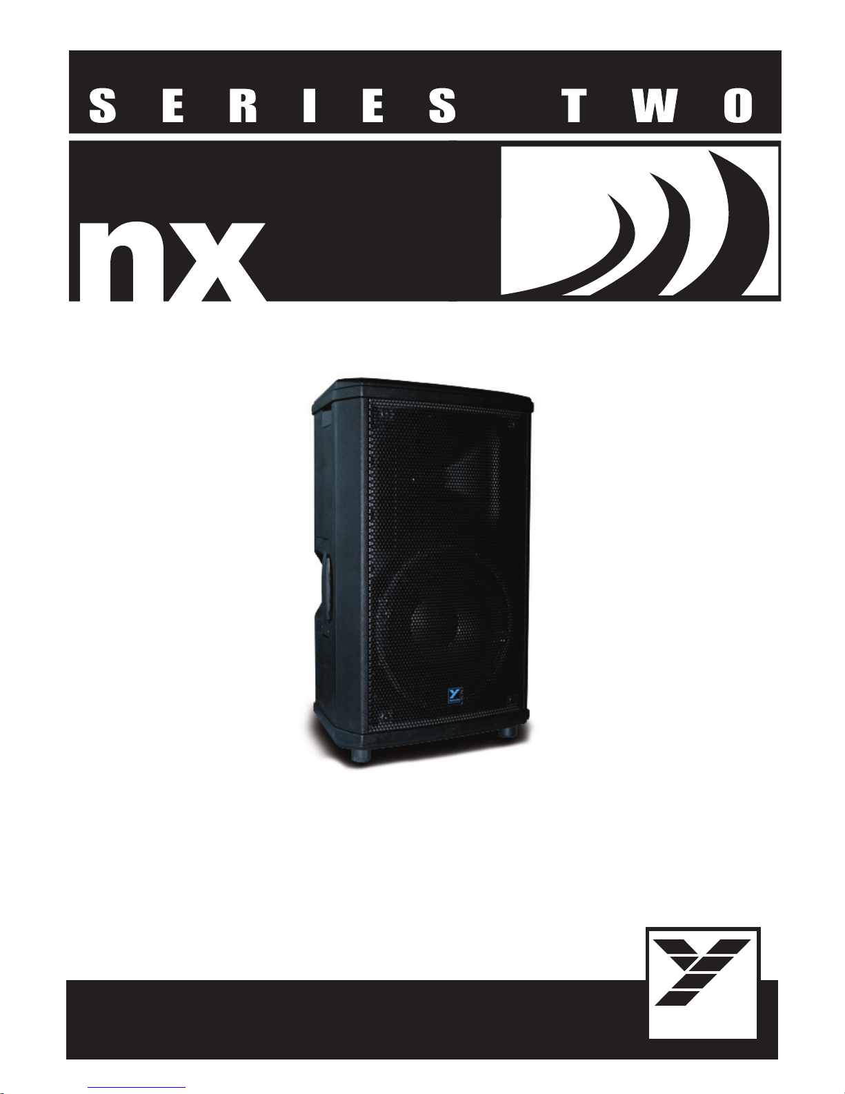
OWNER'S MANUAL
MANUEL de L'UTILISATEUR
TYPE: YS1107
P
300 WATT POWERED LOUDSPEAKER ENCLOSURE
25
Yorkville
Page 2
IMPORTANT SAFETY INSTRUCTIONS
This lightning flash with arrowhead symbol, within
an equilateral triangle, is intended to alert the user to
the presence of uninsulated “dangerous voltage”
magnitude to constitute a risk of electric shock to persons.
Ce symbole d’éclair avec tête de flèche dans un triangle
équilatéral est prévu pour alerter l’utilisateur de la présence d’un
« voltage dangereux » non-isolé à proximité de l’enceinte du
produit qui pourrait être d’ampleur suffisante pour présenter
un risque de choque électrique.
within the product’s enclosure that may be of sufficient
FOLLOW ALL INSTRUCTIONS SUIVEZ TOUTES LES INSTRUCTIONS
Instructions pertaining to a risk of fire,
electric shock, or injury to a person
CAUTION: TO REDUCE THE RISK OF ELECTRIC
SHOCK, DO NOT REMOVE COVER (OR BACK).
NO USER SERVICEABLE PARTS INSIDE.
REFER SERVICING TO QUALIFIED SERVICE PERSONNEL.
THIS DEVICE IS FOR INDOOR USE ONLY!
Read Instructions: The Owner’s Manual should be read and understood before operation
of your unit. Please, save these instructions for future reference and heed all warnings.
Clean only with dry cloth.
Packaging: Keep the box and packaging materials, in case the unit needs to be
returned for service.
Warning: To reduce the risk or fire or electric shock, do not expose this apparatus to rain or
moisture. Do not use this apparatus near water!
Warning: When using electric products, basic precautions should always be followed,
including the following:
Power Sources
Your unit should be connected to a power source only of the voltage specified in the
owners manual or as marked on the unit. This unit has a polarized plug. Do not use
with an extension cord or receptacle unless the plug can be fully inserted. Precau-
tions should be taken so that the grounding scheme on the unit is not defeated. An
apparatus with CLASS I construction shall be connected to a Mains socket outlet with
a protective earthing ground. Where the MAINS plug or an appliance coupler is used
as the disconnect device, the disconnect device shall remain readily operable.
Hazards
Do not place this product on an unstable cart, stand, tripod, bracket or table. The
product may fall, causing serious personal injury and serious damage to the product.
Use only with cart, stand, tripod, bracket, or table recommended by the manufacturer
or sold with the product. Follow the manufacturer’s instructions when installing the
product and use mounting accessories recommended by the manufacturer. Only use
attachments/accessories specified by the manufacturer
Note: Prolonged use of headphones at a high volume may cause
health damage on your ears.
The apparatus should not be exposed to dripping or splashing water; no objects
filled with liquids should be placed on the apparatus.
Terminals marked with the “lightning bolt” are hazardous live; the external wiring
connected to these terminals require installation by an instructed person or the use of
ready made leads or cords.
Ensure that proper ventilation is provided around the appliance. Do not install near
any heat sources such as radiators, heat registers, stoves, or other apparatus
(including amplifiers) that produce heat.
No naked flame sources, such as lighted candles, should be placed on the apparatus.
Power Cord
Do not defeat the safety purpose of the polarized or grounding-type plug. A polarized plug
has two blades with one wider than the other. A grounding type plug has two blades and a
third grounding prong. The wide blade or the third prong are provided for your safety. If the
provided plug does not fit into your outlet, consult an electrician for replacement of the
obsolete outlet. The AC supply cord should be routed so that it is unlikely that it will be
damaged. Protect the power cord from being walked on or pinched particularly at plugs. If
the AC supply cord is damaged DO NOT OPERATE THE UNIT. To completely disconnect
this apparatus from the AC Mains, disconnect the power supply cord plug from the AC
receptacle. The mains plug of the power supply cord shall remain readily operable.
Unplug this apparatus during lightning storms or when unused for long periods of time.
Service
The unit should be serviced only by qualified service personnel. Servicing is required
when the apparatus has been damaged in any way, such as power-supply cord or plug is
damaged, liquid has been spilled or objects have fallen into the apparatus, the apparatus
has been exposed to rain or moisture, does not operate normally, or has been dropped.
Caution: hot surface
Attention: surface chaude
IEC 60417-5041
AVIS: AFIN DE REDUIRE LES RISQUE DE CHOC ELECTRIQUE,
NE CONTIENT AUCUNE PIECE REPARABLE PA R L’UTILISATEUR.
CE PRODUIT EST POUR L’USAGE À L’INTÉREUR SEULEMENT
Veuillez Lire le Manuel: Il contient des informations qui devraient êtres comprises avant
l’opération de votre appareil. Conservez. Gardez S.V.P. ces instructions pour consultations
ultérieures et observez tous les avertissements.
Nettoyez seulement avec le tissu sec.
Emballage: Conservez la boite au cas ou l’appareil devait être retourner pour réparation.
Avertissement: Pour réduire le risque de feu ou la décharge électrique, n'exposez pas
cet appareil à la pluie ou à l'humidité. N’utilisez pas cet appareil près de l’eau!
Attention: Lors de l’utilisation de produits électrique, assurez-vous d’adhérer à des
précautions de bases incluant celle qui suivent:
Alimentation
L’ appareil ne doit être branché qu’à une source d’alimentation correspondant au
voltage spécifié dans le manuel ou tel qu’indiqué sur l’appareil. Cet appareil est équipé
d’une prise d’alimentation polarisée. Ne pas utiliser cet appareil avec un cordon de
raccordement à moins qu’il soit possible d’insérer complètement les trois lames. Des
précautions doivent êtres prises afin d’eviter que le système de mise à la terre de
l’appareil ne soit désengagé. Un appareil construit selon les normes de CLASS I
devrait être raccordé à une prise murale d’alimentation avec connexion intacte de mise
à la masse. Lorsqu’une prise de branchement ou un coupleur d'appareils est utilisée
comme dispositif de débranchement, ce dispositif de débranchement devra demeurer
pleinement fonctionnel avec raccordement à la masse.
Risque
Ne pas placer cet appareil sur un chariot, un support, un trépied ou une table instables.
L’appareil pourrait tomber et blesser quelqu’un ou subir des dommages importants.
Utiliser seulement un chariot, un support, un trépied ou une table recommandés par le
fabricant ou vendus avec le produit. Suivre les instructions du fabricant pour installer
l’appareil et utiliser les accessoires recommandés par le fabricant. Utilisez seulement
les attachements/accessoires indiqués par le fabricant
Il convient de ne pas placer sur l’appareil de sources de flammes nues, telles que
des bougies allumées.
L’appeil ne doit pas être exposé à des égouttements d’eau ou des éclaboussures
et qu’aucun objet rempli de liquide tel que des vases ne doit être placé sur l’appareil.
Assurez que lappareil est fourni de la propre ventilation. Ne procédez pas à
l’installation près de source de chaleur tels que radiateurs, registre de chaleur, fours
ou autres appareils (incluant les amplificateurs) qui produisent de la chaleur.
Les dispositifs marqués d’une symbole “d’éclair” sont des parties dangereuses
au toucher et que les câblages extérieurs connectés à ces dispositifs de
connection extérieure doivent être effectivés par un opérateur formé ou en utilisant
des cordons déjà préparés.
Cordon d’Alimentation
Ne pas enlever le dispositif de sécurité sur la prise polarisée ou la prise avec tige de
mise à la masse du cordon d’alimentation. Une prise polarisée dispose de deux lames
dont une plus large que l’autre. Une prise avec tige de mise à la masse dispose de
deux lames en plus d’une troisième tige qui connecte à la masse. La lame plus large ou
la tige de mise à la masse est prévu pour votre sécurité. La prise murale est désuète si
elle n’est pas conçue pour accepter ce type de prise avec dispositif de sécurité. Dans
ce cas, contactez un électricien pour faire remplacer la prise murale. Évitez
d’endommager le cordon d’alimentation. Protégez le cordon d’alimentation. Assurezvous qu’on ne marche pas dessus et qu’on ne le pince pas en particulier aux prises.
N’UTILISEZ PAS L’APPAREIL si le cordon d’alimentation est endommagé. Pour
débrancher complètement cet appareil de l’alimentation CA principale, déconnectez le
cordon d’alimentation de la prise d’alimentation murale. Le cordon d’alimentation du
bloc d’alimentation de l’appareil doit demeurer pleinement fonctionnel.
Débranchez cet appareil durant les orages ou si inutilisé pendant de longues périodes.
Service
Consultez un technicien qualifié pour l’entretien de votre appareil. L'entretien est
nécessaire quand l'appareil a été endommagé de quelque façon que se soit. Par exemple
si le cordon d’alimentation ou la prise du cordon sont endommagés, si il y a eu du liquide
qui a été renversé à l’intérieur ou des objets sont tombés dans l'appareil, si l'appareil a été
safety-5v0 • November 11/2013
exposé à la pluie ou à l'humidité, si il ne fonctionne pas normalement, ou a été échappé.
The exclamation point within an equilatereal triangle is
intended to alert the user to the presence of important
operating and maintenance (servicing) instructions in
the literature accompanying the appliance.
Le point d’exclamation à l’intérieur d’un triangle
équilatéral est prévu pour alerter l’utilisateur de la
présence d’instructions importantes dans la
littérature accompagnant l’appareil en ce qui
concerne l’opération et la maintenance de cet
S2125A
appareil.
Instructions relatives au risque de feu,
choc électrique, ou blessures aux personnes
N’ENLEVEZ PAS LE COUVERT (OU LE PANNEAU ARRIERE)
CONSULTEZ UN TECHNICIEN QUALIFIE POUR L’ENTRETIENT
Note: L'utilisation prolongée des écouteurs à un volume élevé peut
avoir des conséquences néfastes sur la santé sur vos oreilles. .
Page 3
IMPORTANT SAFETY INSTRUCTIONS (UL60065)
The Lightning Flash with arrowhead
symbol within an equilateral triangle, is
intended to alert the user to the presence
of uninsulated "dangerous voltage" within the
product enclosure that may be of sufficient
magnitude to constute a risk of shock to persons.
operang and maintenance (servicing) instrucons in
the literature accompanying the product
1) Read these instrucons.
2) Keep these instrucons.
3) Heed all warnings.
4) Follow all instrucons.
5) Do not use this apparatus near water.
6) Clean only with dry cloth.
7) Do not block any venlaon openings. Install in accordance with the manufacturer’s instrucons.
8) Do not install near any heat sources such as radiators, heat registers, stoves, or other apparatus (including
amplifiers) that produce heat.
9) Do not defeat the safety purpose of the polarized or grounding-type plug. A polarized plug has two blades
with one wider than the other. A grounding type plug has two blades and a third grounding prong. The
wide blade or the third prongs are provided for your safety. If the provided plug does not fit into your
outlet, consult anelectrician for replacement of the obsolete outlet.
10)Protect the power cord from being walked on or pinched parcularly at plugs, convenience receptacles,
and the point where they exit from the apparatus.
11)Only use aachments/accessories specified by the manufacturer.
12)Use only with the cart, stand, tripod, bracket, or table specified by the manufacturer, or sold with the
apparatus. When a cart is used, use cauon when moving the cart/apparatus combinaon to avoid injury
from p-over.
13)Unplug this apparatus during lightning storms or when unused for long periods of me.
14)Refer all servicing to qualified service personnel. Servicing is required when the apparatus has been
damaged in any way, such as power-supply cord or plug is damaged, liquid has been spilled or objects have
fallen into the apparatus, the apparatus has been exposed to rain or moisture, does not operate normally,
or has been dropped.
WARNING:
• To reduce the risk
of fire or electric shock, do not expose this apparatus to rain or moisture and objects
filled with liquids, such as vases, should not be placed on this apparatus.
• To completely disconnect this apparatus from the ac mains, disconnect the power supply cord plug from
the ac receptacle.
• The mains plug of the power supply cord or appliance coupler shall remain readily accessible.
DO NOT CONNECT TO MAINS POWER SUPPLY WHILE GRILLE IS REMOVED.
TO PREVENT ELECTRIC SHOCK HAZARD,
CAUTION
The exclamaon point within an
equilateral triangle is intended to alert
the user to the presence of important
Page 4
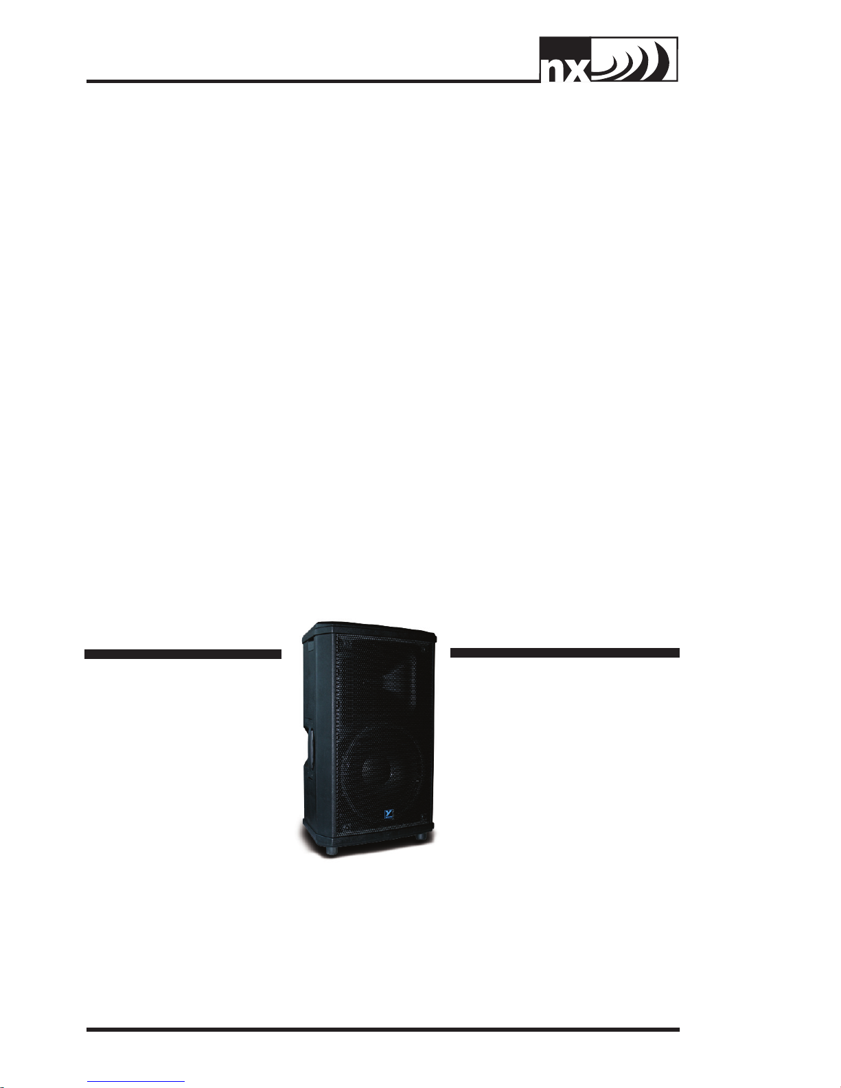
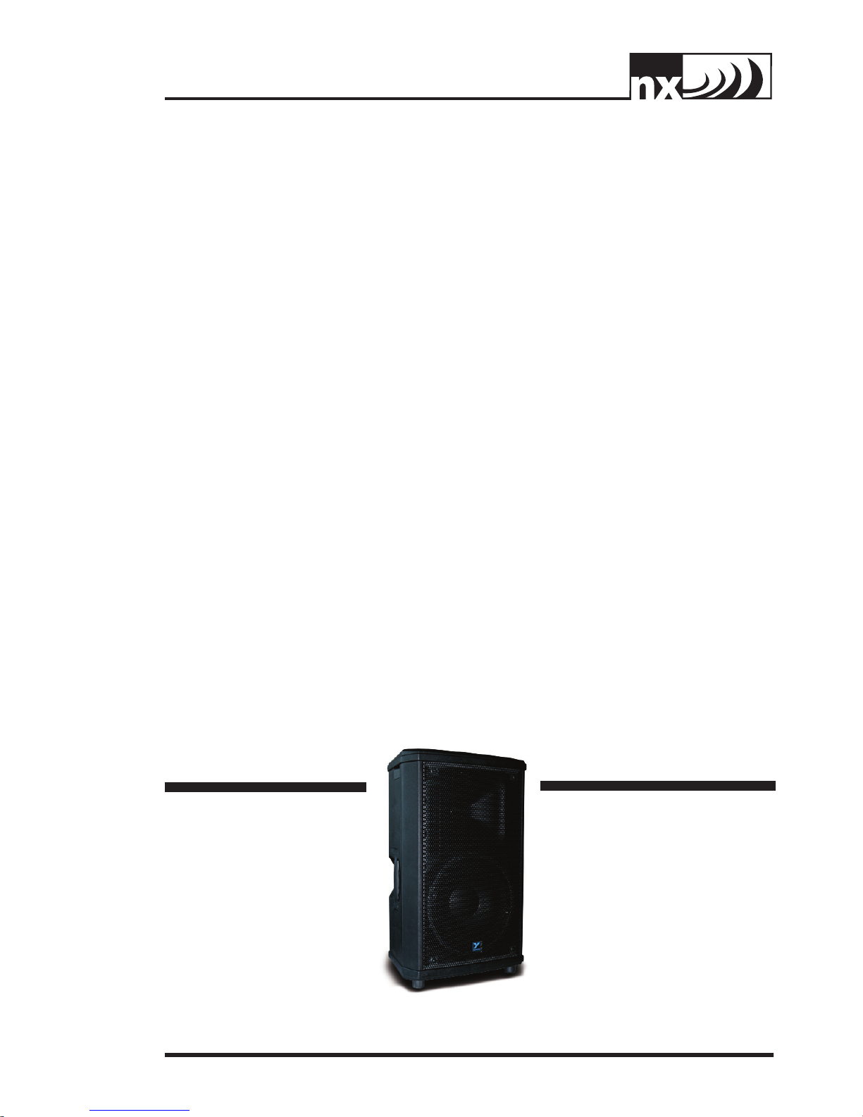
NX25P Series Two - Active Speaker - 600w, 12 inch / 1 inch
The NX25P Series Two offers a great value for a 12-inch and horn active loudspeaker enclosure.
The enclosure uses the same proven design as the NX55P active enclosure. The biamped 600watt (peak) power module has a minimum of controls yet provides maximum versatility making
the NX25P Series Two the ideal solution for many applications.
A 2-band EQ, XLR balanced microphone input and a balanced Combi-jack (XLR / TRS 1/4inch TRS) line input on the power module means the NX25P Series Two can be easily connected
to any source, and setup quickly with a balanced EQ for the room. An XLR balanced line output
allows multiple NX25P Series Two’s to be linked together for use in a horizontal array or for easy
distribution around a large room when used as repeater cabinets.
The horn/tweeter amplifier uses class A/B technology, allowing the horn to produce clean
transients to keep up with the high output of the woofer. The woofer (low frequency) amplifier
uses class-H 2-tier amplifier technology. This achieves a lighter weight and more efficient audio
amplifier with higher headroom and lower operating temperature. Each amplifier has it own
limiter to prevent distortion caused by clipping.
The NX25P Series Two enclosures, like all enclosures in the NX loudspeaker line, have been
designed for maximum versatility. The trapezoid box is ideal for mounting in arrays, or for use as
a monitor cabinet (with well-protected inputs and controls). The NX25P Series Two can easily
be used in any orientation, and close to walls, floors and in close arrays with multiple cabinets.
Particular care was taken designing the components to reduce extraneous heat production.
Features
• Ultra-durable polypropylene construction
• Dual purpose full range and wedge monitor format enclosure
• Ultra-clear reproduction throughout bandwidth
• Lightweight, high efficiency, high tech, 600-watt (peak) biamped power module
• Balanced Combi-jack (XLR/1/4-inch TRS) input
• An XLR output for easy connection for linking and looping
• Direct microphone input with level control
• Two band overall EQ controls
• 12-inch Ceramic Magnet Woofer
• High quality 1-inch High Frequency driver
• Integrated flying hardware (3/8-inch threaded holes)
• Tough, full length metal grille
• Recessed panel
Power Switch and
LED
The Power Switch turns the
power on and off for the NX25P
Series Two enclosure and the
green LED will illuminate when
the power is on also indicating
a properly functioning fuse.
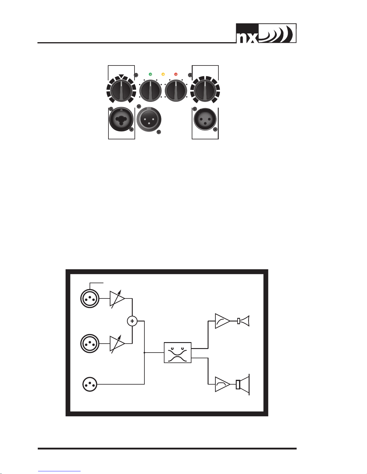
Mic In
The balanced XLR
microphone input can be
used with any dynamic or
condenser microphone.
Line In
The balanced Combi-jack (XLR/1/4-inch
TRS) input can be used with any line source
such as a CD player or an electronic
instrument with a line output. It‘s always
recommended to use balanced sources
2
when possible, this helps prevent
the risk of hum or buzz associated
with unbalanced connections
(especially if the cable is long or the
source is operated from a separate
AC power connection). Since the
Mic In and the Line In each have
their own input and level controls,
they can be used at the same time.
Mix Out
To allow operation of multiple NX25P
Series Two enclosures from a single
source, the Mix Out line output is
provided. It should be connected
to the Line In of the next NX25P Series Two
in the chain. The Line In level control on the
subsequent unit in the chain should be set to
0 dB in order to provide the same output level
as the master enclosure. When connecting
multiple NX25P Series Two enclosures, the
last NX25P Series Two in the chain should be
Page 5
powered off first (and
LINE IN LEVELMIC LEVELPOWER LIMIT CLIP
LINE IN LINK MIC
max
min
max
min
0
BASS
TREBLE
0
+
-
0
+
-
Bass Treble
+24 PHANTOM
132
132
231
P
300 WATT POWERED LOUDSPEAKER ENCLOSURE
MIC IN MIC GAIN
LINE IN
LINK 250 WATTS
TONE CONTROLS
50 WATTS
LEVEL
30hz/5kHz
5kHz
25
powered on last).
Each NX25P Series Two
should be powered
on or off before the
previous NX25P Series
Two in the chain. This
will eliminate unwanted
on/off noises.
Mic Gain
Control
The microphone
level control adjusts
the mic level of the
loudspeaker. It also adjusts the mic level on
all NX25P Series Two enclosures in the chain (if
multiple NX25P Series Two enclosures are used).
Treble and Bass
Controls
These controls affect all
the sound coming out
of a particular NX25P
Series Two enclosure.
These controls do not
affect the sound at the
Mix Out. In a system with
multiple cabinets it will
be necessary to adjust
the Bass, Treble, Mid
and Bass controls on all
individual enclosures.
Limit and Clip LEDs
These LEDs illuminate yellow when signal is
limiting and red when the signal is too large
for the input and is clipping.
3
Page 6
Specification
s
P
300 WATT POWERED LOUDSPEAKER ENCLOSURE
25
System Type
Active or Passive
Peak Power (watts)
Biampable
Biamp Operation Only
Max SPL (dB)
Frequency Response (Hz +/- 3db)
Crossover Frequency (Hz)
Driver Configuration
HF Driver(s)
HF Dispersion (°H x °V)
LF Driver(s)
Total Power (watts)
HF Power Amplifier (watts)
HF Amplifier Type
LF Power Amplifier (watts)
LF Amplifier Type
Power Cable
Power Switch
Power Consumption (typ/max)
Inputs
Inputs - 1/4-inch Jacks
Input Sensitivity (Vrms Sine)
Mixer Controls
Level Controls
Limiter
LED Indicators
Feet
Flying Hardware
Optional Flying Hardware
Bar Handles
Enclosure Materials
Grille
Dimensions (DWH xbackW, inches)
Dimensions (DWH xbackW, cm)
Weight (lbs/kg)
2-Way
Active
600
Self Powered
Yes
125
55 - 26k
4000
12 inch / 1 inch
1 inch Throat, Ceramic Magnet, 1.4 inch PETP Film
80 x 50
12 inch Ceramic Magnet
300
50
Class A/B
250
Two Tier Class H
Yes
Yes
120 / 310 Va
2
1 Line / 1 Mic (XLR Combi jacks)
+4dBv / 1.23V
Mic Gain
Line In Gain
Bass/Treble
Line/Mic
Yes
Power,Limit,Clip
Yes
2 (Top), 2 (Bottom), 1 (Pullback)
NX Flyware
1 (Side)
Injection molded Polypropylene
Perforated Metal
12.25 x 16 x 26.5 x 9
31.12 x 40.6 x 67.3 x 22.9
45.9 / 20.8
4
Page 7
NX25P Series Two – Enceinte Active 600w, 12 Pouces / 1 Pouce
La NX25P Series Two vous procure une valeur exceptionnelle en ce qui concerne les enceintes
actives avec HP de 12 pouces et pavillon. L’enceinte est de la même conception que
l’enceinte passive NX55P qui a déjà fait ses preuves. Le module de bi-amplification de 600
watts dispose d’un minimum de contrôle mais il offre toutefois une très grande polyvalence. La
NX25P sera la solution idéale pour une grande variété d’application.
Grâce à son égalisateur à 2 bandes, son entrée symétrique XLR pour microphone et une
entrée ligne (XLR/PBM 1/4-pouce) symétrique combi-jack au module d’amplification de
puissance, la NX25P Series Two peut facilement être raccordée à n’importe quelle source et son
égalisateur permet en plus d’équilibrer la tonalité pour un rendement optimum dans la salle.
Une sortie ligne symétrique XLR permet le branchement de multiple NX25P raccordés ensemble
pour utilisation en disposition circulaire ou pour distribution facile dans une grande salle lorsque
utilisé comme enceinte “repeater.”
L’amplificateur pour Pavillon/Tweeter utilise une technologie de classe A/B. Cela permet
au pavillon de reproduire des transitoires claires offrant du même coup une reproduction
équilibrée avec le niveau de sortie élevé du haut-parleur de graves. L’amplificateur pour
woofer, ou fréquences graves, utilise une technologie de classe H à deux étages. Cela permet
d’obtenir une conception légère, une amplification plus efficace avec une plus grande
extension dynamique et une température d’opération réduite. Chaque amplificateur dispose
de son propre limiteur pour aider à prévenir la distorsion causée par l’écrêtage.
L’enceinte de la NX25P Series Two, comme toutes les enceintes de la série NX, a été
conçu pour offrir une polyvalence optimale. Le boitier en forme trapézoïdal est idéal pour
l’assemblage en disposition circulaire ou pour utilisation comme enceinte de retour (avec
entrées et contrôle bien protégé.) La NX25P Series Two peut facilement être utilisé dans
n’importe quelle orientation, près des murs, sur le plancher et en disposition circulaire
rapprochée dans les installations à multiples enceintes. Un grand soin a été apporté lors de la
conception des composantes pour réduire la production de chaleur.
Caractéristiques
• Construction en polypropylène Ultra-durable
• Format d’enceinte à double utilité pour applications pleine bandes ou moniteur de scène
• Reproduction ultra-claire à travers toute la gamme de fréquences
• Module haute technologie léger et à haute efficacité de bi-amplification avec
puissance de 600 watts (pointe)
• Entrées combi-jack XLR/1/4-pouce PBM
• Sortie XLR pour faciliter les raccordements « linking » et « looping »
• Entrée direct pour microphone avec contrôle de niveau
• Contrôles d’égalisateur général à deux bandes
• Woofer de 12 pouces avec aimant en céramique
• Driver haute qualité de 1 pouce pour fréquences aigües
• Quincaillerie de suspension intégrée (trous filetés 3/8-pouce)
• Grille robuste de pleine grandeur
• Panneau encastré
Interrupteur et DEL
d’Alimentation
L’interrupteur d’alimentation
met l’enceinte NX25P Series
Two sous et hors tension et
la DEL verte s’allume pour
indiquer que l’appareil est
en marche et que le fusible
fonctionne correctement.
Entrée Microphone
L’entrée symétrique XLR pour
microphone peut être utilisé
avec tous les microphones
dynamiques ou ceux à condensateur.
Entrée Ligne
L’entrée symétrique combi- jack
XLR/1/4-pouce peut être utilisé
avec n’importe quelle source de
niveau ligne comme lecteur CD ou
instrument électronique avec sortie
ligne. Il est toujours recommandé
d’utiliser des sources symétriques.
Cela aidera à prévenir les risques de
bruits et bourdonnements associés
aux raccordements asymétriques,
en particulier si le câble est long
ou si la source est branchée à une
alimentation CA séparée. Les entrées
« Mic In » et « Line In » dispose chacun
5
Page 8
de leurs propres
LINE IN LEVELMIC LEVELPOWER LIMIT CLIP
LINE IN LINK MIC
max
min
max
min
0
BASS
TREBLE
0
+
-
0
+
-
Bass Tr eble
+24 PHANTOM
132
132
231
P
300 WATT POWERED LOUDSPEAKER ENCLOSURE
MIC IN MIC GAIN
LINE IN
LINK 250 WATTS
TONE CONTROLS
50 WATTS
LEVEL
30hz/5kHz
5kHz
25
contrôles d’entrée et
de niveau, ils peuvent
donc être utilisées en
même temps.
Sortie Mix
Cette sortie ligne
est prévue pour
permettre l’opération
avec de multiples
enceintes NX25P Series
Two, à partir d’une
seule source. Elle
devrait être raccordé
à l’entrée ligne de
la prochaine NX25P
Series Two dans l’ensemble. Le contrôle
niveau « Line In » sur l’unité suivante dans
la chaîne devrait être réglé à 0 dB afin de
fournir le même niveau de sortie comme
l’enceinte principale. Lorsque vous raccordez
plusieurs enceintes NX25P Series Two, la
dernière NX25P Series Two de la chaîne
devrait être éteinte en premier (et allumé en
dernier.) Chaque NX25P Series Two devrait
être éteinte ou allumé avant la NX25P Series
Two précédente dans la chaîne. Cela
éliminera les bruits lorsque la NX25P Series
Two est allumées ou quand elle est éteinte.
Contrôle de Gain
Pour Microphone
Le contrôle de niveau
pour microphone
ajuste le niveau
du microphone de
l’enceinte. Il ajuste
aussi le niveau du
microphone pour toutes
les enceintes NX25P
dans une chaîne lors
d’opération à multiple
NX25P Series Two.
Contrôles Treble
et Bass
Ces contrôles affectent tous les sons
provenant de l’enceinte NX25P Series
Two. Ils n’affectent toutefois pas le signal
présent à la prise de sortie « Mix Out ». Dans
un système à multiples enceintes, il sera
nécessaire d’ajuster les contrôles Bass, Mid et
Treble individuellement sur chaque enceinte.
DEL Signal / Limit
Ces DEL s’illuminent en jaune quand le signal
déclenche le limiteur et en rouge quand le
niveau de signal est trop élevé pour l’entrée
et produit de l’écrêtage.
6
Page 9
Spécifications
P
300 WATT POWERED LOUDSPEAKER ENCLOSURE
25
Type de système
Active ou Passive
Peak Power (watts)
Capacité de Bi-amplification
Opération en mode de Biamplification seulement
Pression Sonore Maximum (dB)
Réponse en Fréquences (Hz +/- 3db)
Fréquence de coupure (Hz)
Configuration de haut-parleur
Driver(s) pour aiguës
Dispersion pour fréquences aiguës(°H x °V)
Driver(s) pour graves
Puissance Totale (watts)
Amplificateur de puissance pour Aiguës (watts)
Type d’amplificateur pour les aiguës
Amplificateur de puissance pour les Graves (watts)
Type d’amplificateur pour les graves
Cordon d’alimentation
Commutateur de mise en marche
Consommation de puissance (typ/max)
Entrées
Entrées - 1/4-pouce Jacks
Sensibilité d’entrée (Vrms Sinusoïdal)
Contrôles du mixeur
Contrôles de Niveau
Limiteur
DEL indicatrices
Pieds
Quincaillerie de suspension
Quincaillerie de suspension Optionnelle
Poigné
Matériaux de construction
Grille
Dimensions (PLH x L arrière, pouces) 12.25 x 16 x 26.5 x 9
Dimensions (PLH x L arrière, cm) 31.12 x 40.6 x 67.3 x 22.9
Poids (livres / kg)
2-Voies
Active
600
Auto amplification
Oui
125
55 - 26k
4000
12 pouces / 1 pouce
Ouverture de 1 pouce, Aimant en céramique, Pellicule PETP 1.4 pouce
80 x 50
12 pouces Aimant de céramique
300
50
Classe A/B
250
Deux étages Classe H
Oui
Oui
120 / 310 Va
2
1 Ligne / 1 Mic (XLR Combi jacks)
+4dBv / 1.23V
Gain pour microphone
Gain Entré Ligne
Graves / Aiguës
Ligne, Microphone
Oui
Alimentation, Limite, Clip
Oui
2 (Dessus), 2 (Dessous), 1 (Arrière)
Quincaillerie NX
1 (Côté)
Polypropylène moulé par injection
Métal Perforé
45.9 / 20.8
7
Page 10
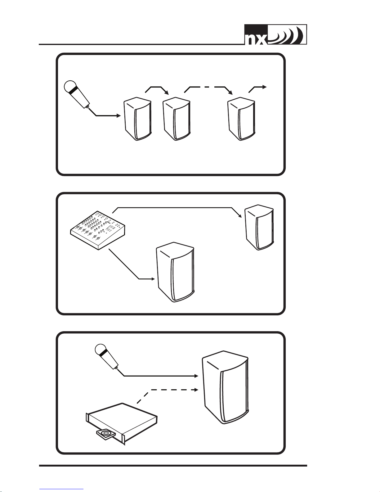
TO MIC IN
MIXER OUTPUT
MIXER OUTPUT
LINE IN LINE INMIX OUTMIX OUT
TO MORE NX250Ps
MICROPHONE with MULTIPLE NX25Ps
TO LINE IN
config-01e-nx25p-1v0.eps
MIC
OR
CD PLAYER
TO LINE IN
config-02e-nx25p-1v0.epsconfig-03e-nx25p-1v0.eps
STEREO P.A., with EXTERNAL MIXER
TO MIC IN
TO LINE IN
8
ONE MIC OR CD PLAYER
Page 11
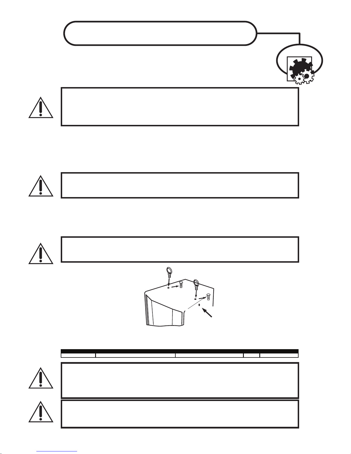
4 fly points - 2 top + 2 bottom + pull back 1/4-inch weight of cabinet only
NX25P
EYEBOLT INSTALLATION
Remo v e
Flat-Head Bolt and
replace with For g ed Shoulder Ey ebolt!
DO NO T Remo v e
Flat-Head Bolts
on the Side of Cabinet/s .
1. DESCRIPTION
Many of the popular models in the Yo rkville speaker cabinet line are now equipped with flying
hardware for overhead suspension applications. Depending on the model, two or more internal
braces have been provided for rigging purposes. Each brace contains two bolt holes and provides
center-of-gravity fly-points for use with in-line or angular loads. Many of the models will support
additional suspended cabinets according to their specified working load limits.
IMPORTANT!!
THE RIGGING OF LOUDSPEAKER SYSTEMS IS AN EXTREMELY SERIOUS MATTER. OVERHEAD RIGGING REQUIRES EXTENSIVE
EXPERIENCE, INCLUDING (BUT NOT LIMITED TO) CALCULATING WORKING LOAD LIMITS, HARDWARE INSTALLATION, AND
PERIODIC SAFETY INSPECTION OF ALL HARDWARE AND CABINETRY. IF YOU LACK THESE QUALIFICATIONS, DO NOT ATTEMPT
THE INSTALLATION YOURSELF, BUT INSTEAD USE A PROFESSIONAL STRUCTURAL RIGGER. IMPROPER INSTALLATION CAN
RESULT IN BODILY INJURY OR DEATH. CONSULT A STRUCTURAL ENGINEER TO CALCULATE ADDED LOADS FOR A BUILDING.
STRUCTURAL REINFORCEMENT MAY BE NECESSARY TO INSURE A SAFE INSTALLATION.
2. REQUIRED TOOLS
1/4-20 Hex Wrench
Thread lock adhesive (Removable Type)
3. EYEBOLT INSTALLATION
a) Using a 1/4-20 hex wrench, remove the flat head bolts from the top or bottom of the speaker enclosure to
expose the tapped holes (on TX models, the flat head bolts are located within the track rails), as shown below. Be
sure to keep these handy as they will be needed to seal the cabinet after the eyebolts are removed.
IMPORTANT!!
USE ONLY LOAD RATED FORGED EYEBOLTS. THESE MAY BE PURCHASED THROUGH YORKVILLE SOUND OR ATM FLY- WARE™.
TO INSURE CABINET-BRACING STRENGTH, MAKE SURE ALL FLY-POINTS ARE SECURED WITH EITHER AN EYEBOLT OR FLAT
HEAD HEX BOLT.
b) Place a drop of thread-lock adhesive on the threads of the eyebolt and insert one into exposed hole. Tighten each
eyebolt by hand until its fits snugly against the cabinet. Further tighten each eyebolt by rotating it another half turn. Be
sure to insert eyebolts in the threaded hole directly in-line with the suspension cable. Always follow the eyebolt
manufacturers installation and use instructions.
c) Suspend each cabinet according to working load calculations and practices recommended by the rigging
hardware manufacturer.
IMPORTANT!!
ON MODELS WITH ONLY TWO TOP SUSPENSION POINTS THE SUPPLIED PULL BACK AT THE REAR OF THE BOTTOM
CENTER PANEL OF THE CABINET IS NOT TO BE USED AS A SUSPENSION POINT. THIS POINT TO BE USED FOR PULL BACK
PURPOSES ONLY.
IMPORTANT!!
READ ALL ENCLOSED INSTRUCTIONS ABOUT PROPER USE OF HARDWARE. TO INSURE PROPER INSTALLATION, FOR
TECHNICAL INFORMATION ON SUSPENSION TECHNIQUES AND EXTERIOR ACCESSORY INFORMATION WE SUGGEST
CALLING ATM FLY- WARES TECHNICAL SERVICES IN THE UNITED STATES AT (310)639-8282 MONDAY THROUGH FRIDAY FROM
9 AM TO 6 PM (PST) OR FAX AT (310)639-8284. YORKVILLE SOUND MAKES NO CLAIMS AS TO THE SAFETY OF THE
ENCLOSURES IF RECOMMENDED LOAD LIMITS AND HARDWARE ARE NOT STRICTLY ADHERED TO. NOR DOES IT MAKE ANY
SAFETY CLAIMS TO THE RESULTANT INSTALLATION.
IMPORTANT!!
TRACK RAILINGS: UNITS THAT INCORPORATE THE TRACK RAILING SYSTEM HAVE THE SAME WORKING LOAD LIMITS AS
THEY DO WHEN THEY ARE USED WITH EYEBOLTS. THESE RATINGS MAY BE LIMITED AND BASED ON THE RATINGS OF THE
TRACK FITTINGS THEMSELVES. PLEASE ENSURE THAT THE RATING OF THE CERTIFIED TRACK FITTINGS EXCEEDS
NECESSARY WORKING LOAD LIMITS
.
4. WORKING LOAD LIMITS
Specified working load limits have been determined for the enclosure as follows:
Page 12
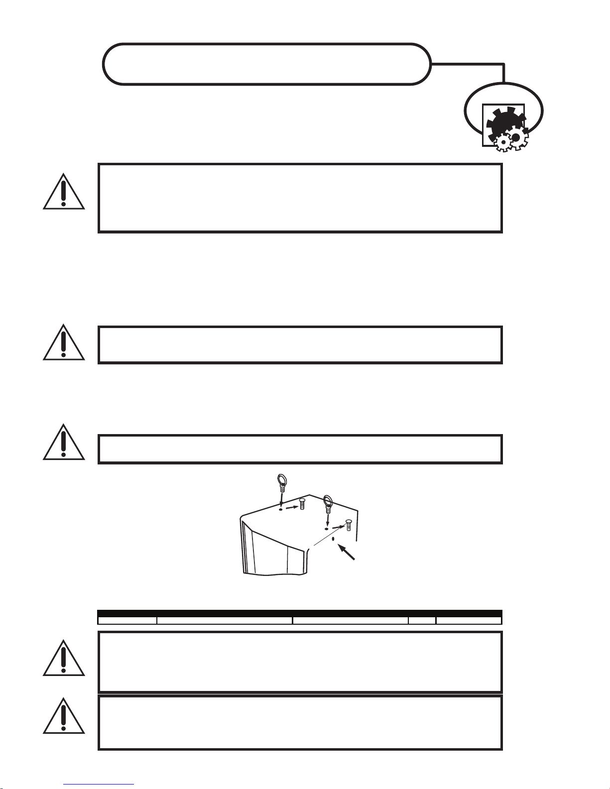
EYEBOLT INSTALLATION
1. DESCRIPTION
Plusieurs des modèles populaires de la ligne d'enceinte à haut-parleur Yo rkville sont maintenant
équipés de quincaillerie de montage pour les applications requérant une suspension aérienne.
Dépendamment du modèle, deux ou plusieurs attaches internes sont prévues pour de tels
montages. Chaque attache contient deux trous de boulon et offre des points de montage centre de
gravité pour utilisation avec charges droites ou anguleuses. Plusieurs des modèles permettent la
suspension de cabinets additionnels selon leur limite de charge de travail spécifique.
IMPORTANT!!
IMPLIQUANT UNE SUSPENSION AÉRIENNE NÉCESSITENT UNE CONNAISSANCE APPROFONDIE, INCLUANT (MAIS NON-LIMITÉE)
AU CALCUL DES LIMITES DE CHARGE DE TRAVAIL, LA QUINCAILLERIE D'INSTALLATION, ET INSPECTIONS PÉRIODIQUES DE
SÉCURITÉ DE TOUTE LA QUINCAILLERIE ET DE L'ÉBÉNISTERIE. SI VOUS N'AVEZ PAS CES QUALIFICATIONS, NE TENTEZ PAS DE
FAIRE VOUS-MÊME L'INSTALLATION, AYEZ PLUTÔT RECOURS À UN PROFESSIONNEL DU DOMAINE. UNE INSTALLATION
INADÉQUATE PEUT CAUSER DES BLESSURES CORPORELLES OU MÊME LA MORT. CONSULTEZ UN INGÉNIEUR EN STRUCTURE
POUR CALCULER LA CHARGES ADDITIONNELLE AJOUTÉE AU BÂTIMENT. UN RENFORCEMENT DE LA STRUCTURE DU
BÂTIMENT POURRAIT ÊTRE NÉCESSAIRE POUR ASSURER UNE INSTALLATION SÛRE.
2. OUTILS REQUIS
Clé Hex 1/4-20
Adhésif de verrouillage pour filetage (Type amovible)
3. INSTALLATION DES BOULONS À OEIL
a) À l'aide d'une Clé Hex 1/4-20, enlevez le boulon à tête plate du dessus ou du dessous de l'enceinte à
haut-parleur pour découvrir les trous filetés (sur les modèles TX, les boulons à tête plate sont situés à l'intérieur
des quincailleries de montage intégré), tel qu'indiqué ci-dessous.
Assurez-vous de ne pas perdre ces boulons à tête plate. Vous devrez les ré-utiliser pour fermer hermétiquement
le cabinet quand les boulons oeil seront enlevés.
IMPORTANT!!
LES PROCURER DE YORKVILLE SOUND OU ATM FLYWARE ™. POUR PRÉSERVER UNE FORCE MAXIMALE DE
L'ENTRETOISEMENT DU CABINET, ASSUREZ-VOUS QUE TOUS LES POINTS DE SUSPENSION SONT FIXÉS SOLIDEMENT AVEC
SOIT UN BOULON À ŒIL, SOIT UN BOULON HEX À TÊTE PLATE
b) Placez une goutte d'adhésif de verrouillage sur le filetage du boulon à oeil et placez-en une dans le trou exposé.
Resserrez chaque boulon à oeil à la main jusqu'à ce qu'ils soient bien serrés contre l'enceinte. Serrez encore
chaque boulon à œil en les tournant un autre demi-tour.
Assurez-vous d'insérer les boulons à oeil dans les trous filetés directement en ligne avec le câble de suspension.
Toujours suivre les instructions d'installation et d'utilisation du fabricant des boulons à oeil.
c) Suspendez chaque enceinte selon le calcul de charge de travail et les pratiques recommandées par le
fabricant de la quincaillerie de montage.
IMPORTANT!!
POINT DE TIRE À L'ARRIÈRE SUR LE PANNEAU CENTRAL DU BAS. CE POINT DE TIRE NE DOIT PAS ÊTRE UTILISÉ COMME POINT
DE SUSPENSION. CE POINT DE TIRE NE DOIT SEULEMENT ÊTRE UTILISÉ QUE POUR TIRER L'ENCEINTE VERS L'ARRIÈRE..
LE MONTAGE DE SYSTÈME DE HAUT-PARLEUR EST UNE AFFAIRE TRÈS SÉRIEUSE. LES MONTAGES
N'UTILISEZ QUE DES BOULONS À OEIL CLASSIFIÉ POUR LES CHARGES REQUISES. VOUS POUVEZ VOUS
LES MODÈLES ÉQUIPÉS DE SEULEMENT DEUX POINT DE SUSPENSION SUR LE DESSUS, SONT DOTÉ D'UN
Remplacez-le avec un boulon à oeil forger!
Enlevez le Boulon à tête plate et
N'enlevez pas les boulons à tête
plate sur le côté de l'enceinte/s
4. LIMITES DE CHARGE DE TRAVAIL
Les limites de charge spécifiées ont été déterminées pour chaque enceinte comme suit:
NX25P
IMPORTANT!! LIRE TOUTE LA DOCUMENTATION INCLUSE AU SUJET DE L'UTILISATION APPROPRIÉ DE LA QUINCAILLERIE.
POUR ASSURER UNE BONNE INSTALLATION, POUR OBTENIR DE L'INFORMATION TECHNIQUE SUR LES DIVERSES
TECHNIQUES DE SUSPENSION ET POUR OBTENIR DE L'INFORMATION SUR LES ACCESOIRES EXTÉRIEURS NOUS VOUS
SUGGÉRONS D'APPELER LE SERVICE TECHNIQUE DE ATM FLY- WARE AUX ETATS-UNIS AU (310)639-8282 DU LUNDI AU
VENDREDI DE 9 AM À 6 PM (HSP) OU PAR FAX AU (310)639-8284. YORKVILLE SOUND NE GARANTIE PAS UNE UTILISATION
SÉCURITAIRE DES ENCEINTES SI LES LIMITES DE CHARGE RECOMMANDÉES NE SONT PAS RESPECTÉES ET SI VOUS
N'ADHÉREZ PAS STRICTEMENT À LA LISTE DE QUINCAILLERIE RECOMMANDÉE.
IMPORTANT!! RAILS DE MONTAGE (TRACK RAILLINGS): LES ENCEINTES INCORPORANT LE SYSTEME DE RAIL DE MONTAGE
ONT LES MÊMES LIMITES DE CHARGE DE TRAVAIL QU'ILS SOIENT SUSPENDUS AVEC LE SYSTÈME DE RAIL OU AVEC LES
BOULONS À OEIL. CES VALEURS ASSIGNÉES DE LIMITE DE CHARGE PEUVENT ÊTRES LIMITÉS ET BASÉS SUR LA VALEUR
DE LIMITE DE CHARGE ASSIGNÉE AUX APPAREILLAGES DE RAIL (TRACK FITTINGS) ELLE-MÊMES. ASSUREZ-VOUS S.V.P. QUE
LA VALEUR ASSIGNÉE DE LIMITE CHARGE DE TRAVAIL SUR LES APPAREILLAGES CERTIFIÉS DE RAIL (TRACK FITTINGS)
EXÈDE LES LIMITES NÉCESSAIRES DE CHARGE DE TRAVAIL.
4 fly points - 2 top + 2 bottom + pull back 1/4-inch weight of cabinet only
Page 13
Two
&
Two & Ten Year Warranty
Ten
Unlimited Warranty
Yorkville's two and ten-year unlimited warranty on this product is transferable
and does not require registration with Yorkville Sound or your dealer. If this
product should fail for any reason within two years of the original purchase
date (ten years for the wooden enclosure), simply return it to your Yorkville
dealer with original proof of purchase and it will be repaired free of charge.
This includes all Yorkville products, except for the YSM Series studio
monitors, Coliseum Mini Series and TX Series Loudspeakers.
Freight charges, consequential damages, weather damage, damage as a result
of improper installation, damages due to exposure to extreme humidity, accident
or natural disaster are excluded under the terms of this warranty. Warranty does
not cover consumables such as vacuum tubes or par bulbs. See your Yorkville
dealer for more details. Warranty valid only in Canada and the United States.
Garantie Illimitée
La garantie illimitée de deux et dix ans de ce produit est transférable. Il n`est pas
nécessaire de faire enregistrer votre nom auprès de Yorkville Sound ou de votre
détaillant. Si, pour une raison quelconque, ce produit devient défectueux durant
les deux années qui suivent la date d`achat initial (dix ans pour l`ébénisterie),
retournez-le simplement à votre détaillant Yorkville avec la preuve d`achat original
et il sera réparé gratuitement. Ceci inclus tous les produits Yorkville à l`exception
de la série de moniteurs de studio YSM, la mini série Coliseum et de la série TX.
Les frais de port et de manutention ainsi que les dommages indirects ou
dommages causés par désastres naturels, extrême humidité ou mauvaise
installation ne sont pas couverts par cette garantie. Cette garantie ne couvre
pas les produits consommables tels que lampe d`amplificateur ou ampoules
"PAR". Voir votre détaillant Yorkville pour plus de détails. Cette garantie n’est
valide qu’au Canada et aux États Unis d’Amérique.
REAL Gear.
REAL People.
Canada
Voice: (905) 837-8481
Fax: (905) 837-8746
www.yorkville.com
U.S.A.
Voice: (716) 297-2920
Fax: (716) 297-3689
Yorkville Sound
550 Granite Court
Pickering, Ontario
L1W-3Y8 CANADA
Yorkville Sound Inc.
4625 Witmer Industrial Estate
Niagara Falls, New York
14305 USA
Printed in Canada
Page 14

WORLD HEADQUARTERS
CANADA
U.S.A.
Yorkville Sound
550 Granite Court
Pickering, Ontario
L1W-3Y8 CANADA
Voice: (905) 837-8481
Fax: (905) 837-8746
Yorkville Sound Inc.
4625 Witmer Industrial Estate
Niagara Falls, New York
14305 USA
Voice: (716) 297-2920
Fax: (716) 297-3689
Manual-Owners-nx25p-2-00-1v5 • January 14, 2014
 Loading...