

YORKVILLE K4 Service Manual
U.S.A.
Yorkville Sound Inc.
4625 Witmer Industrial Estate
Niagara Falls, New York
14305 USA
Voice: (716) 297-2920
Fax: (716) 297-3689
WORLD HEADQUARTERS
WEB ACCESS: http://www.yorkville.com
CANADA
Yorkville Sound
550 Granite Court
Pickering, Ontario
L1W-3Y8 CANADA
Voice: (905) 837-8481
Fax: (905) 837-8746
Quality and Innovation Since 1963
Printed in Canada
SERVICE MANUAL
K4
MODEL TYPE: YS1045

IMPORTANT SAFETY INSTRUCTIONS
INSTRUCTIONS PERTAINING TO A
RISK OF FIRE, ELECTRIC SHOCK,
OR INJURY TO PERSONS
CAUTION:
TO REDUCE THE RISK OF ELECTRIC SHOCK, DO
NOT REMOVE COVER (OR BACK).
NO USER SERVICEABLE PARTS INSIDE.
REFER SERVICING TO QUALIFIED
SERVICE PERSONNEL.
Read Instructions
The Owner’s Manualshould be read and understood
before operation of your unit. Please, save these instructions for future reference.
Packaging
Keep the box and packaging materials, in case the unit
needs to be returned for service.
Warning
When using electric products, basic precautions should
always be followed, including the following:
Power Sources
Your unit should be connected to a power source only of the voltage
specified in the owners manual or as marked on the unit. This unit has a
polarized plug. Do not use with an extension cord or receptacle unless
the plug can be fully inserted. Precautions should be taken so that the
grounding scheme on the unit is not defeated.
Hazards
Do not place this product on an unstable cart, stand, tripod, bracket or
table. The product may fall, causing serious personal injury and serious
damage to the product. Use only with cart, stand, tripod, bracket, or
table recommended by the manufacturer or sold with the product.
Follow the manufacturer’s instructions when installing the product and
use mounting accessories recommended by the manufacturer.
The apparatus should not be exposed to dripping or splashing water;
no objects filled with liquids should be placed on the apparatus.
Terminals marked with the “lightning bolt” are hazardous live; the
external wiring connected to these terminals require installation by an
instructed person or the use of ready made leads or cords.
Ensure that proper ventilation is provided around the appliance.
No naked flame sources, such as lighted candles, should be
placed on the apparatus.
Power Cord
The AC supply cord should be routed so that it is unlikely that it will be
damaged. If the AC supply cord is damaged DO NOT OPERATE THE UNIT.
Service
The unit should be serviced only by qualified service personnel.
INSTRUCTIONS RELATIVES AU RISQUE
DE FEU, CHOC ÉLECTRIQUE, OU
BLESSURES AUX PERSONNES
AVIS:
AFIN DE REDUIRE LES RISQUE DE CHOC ELECTRIQUE,
N’ENLEVEZ PAS LE COUVERT (OU LE PANNEAU ARRIERE)
NE CONTIENT AUCUNE PIECE
REPARABLE PAR L’UTILISATEUR.
CONSULTEZ UN TECHNICIEN QUALIFIE
POUR L’ENTRETIENT
Veuillez Lire le Manuel
Il contient des informations qui devraient êtres comprises
avant l’opération de votre appareil. Conservez S.V.P. ces
instructions pour consultations ultérieures.
Emballage
Conservez la boite au cas ou l’appareil devait être
retourner pour réparation.
Attention:
Lors de l’utilisation de produits électrique, assurezvous d’adhérer à des précautions de bases incluant
celle qui suivent:
Alimentation
L’appareil ne doit être branché qu’à une source d’alimentation
correspondant au voltage spécifié dans le manuel ou tel qu’indiqué sur
l’appareil. Cet appareil est équipé d’une prise d’alimentation polarisée.
Ne pas utiliser cet appareil avec un cordon de raccordement à moins
qu’il soit possible d’insérer complètement les trois lames. Des
précautions doivent êtres prises afin d’eviter que le système de mise à
la terre de l’appareil ne soit désengagé.
Risque
Ne pas placer cet appareil sur un chariot, un support, un trépied ou une
table instables. L’appareil pourrait tomber et blesser quelqu’un ou subir
des dommages importants. Utiliser seulement un chariot, un support,
un trépied ou une table recommandés par le fabricant ou vendus avec
le produit. Suivre les instructions du fabricant pour installer l’appareil et
utiliser les accessoires recommandés par le fabricant.
Il convient de ne pas placer sur l’appareil de sources de flammes
nues, telles que des bougies allumées.
L’appeil ne doit pas être exposé à des égouttements d’eau ou des
éclaboussures et qu’aucun objet rempli de liquide tel que des vases
ne doit être placé sur l’appareil.
Assurez que lappareil est fourni de la propre ventilation.
Les dispositifs marqués d’une symbole “d’éclair” sont des parties
dangereuses au toucher et que les câblages extérieurs connectés à
ces dispositifs de connection extérieure doivent être effectivés par un
opérateur formé ou en utilisant des cordons déjà préparés.
Cordon d’Alimentation
Évitez d’endommager le cordon d’alimentation. N’UTILISEZ PAS
L’APPAREIL si le cordon d’alimentation est endommagé.
Service
Consultez un technicien qualifié pour l’entretien de votre appareil.
safety-4v3.eps • Oct. 26/05

K4 Parts List 5/18/2006
YS # Description Qty. YS # Description Qty. YS # Description Qty. YS # Description Qty.
6554 BLUE 3MM LED 3V9 20MA TLHB440VISHAY 1 5281 _10U 16V 20%CAP T&R RAD .2"NP 2 2011 1/4W 11R3 1%FLAME PROOF T&R RES 2 8741 4-40 X 1/2 PAN PH MS JS500 2
6405 RED 3MM LED 1V7 5MA BRT 5 5282 _10U 16V 20%CAP T&R 5X7MM .2"NP 2 4815 1/4W 12R 5% T&R RES 4 8842 #4 X 5/16 PAN QUAD TYPE A JS500 BLK 8
6408 GRN 3MM LED 1V9 5MA FROSTED 1 5629 _10U 160V 20%CAP BLK 10X13MM EL 9 4612 1/2W 18R 5% T&R RES 2 8807 6-32 X 5/16 PAN PH MS JS500 2
6425 BAV21 200V 0A25 DIODE T&R 6 5945 _10U 63V 20%CAP T&R RAD .2"EL 7 4812 1/4W 18R 5% T&R RES 1 8801 6-32 X 3/8 PAN PH TAPTITE JS500 17
6825 1N4148 75V 0A45 DIODE T&R 41 5260 _22U 50V 20%CAP T&R RAD .2"EL 2 4618 1/2W 22R 5% T&R RES 3 8829 6-32 X 3/8 FLAT PH TAPTITE BO#4 HEA 22
6438 1N4007 400V 1A0 DIODE T&R 9 5631 _22U 50V 20%CAP T&R 6X7MM .2"EL 10 4817 1/4W 47R 5% T&R RES 4 8761 6-32 X 1/2 PAN PHIL MS ZINC CLEAR 4
6434 6A2 200V 6A0 DIODE 8 5265 _68U 25V 20%CAP T&R RAD .2"EL 2 4811 1/4W 68R 5% T&R RES 1 8806 6-32 X 1/2 PAN PH TAPTITE JS500 6
6733 BAT85 30V 0A2 DIODE SCHTKYT&R 10 5879 100U 16V 20%CAP T&R 8X7MM .2"EL 4 4912 1/4W 75R 5% T&R RES 1 8878 #6 X 2" PAN PHIL TYPE A JS500 BLACK 4
6439 1N5225B 3V0 0W5 ZENER 5% T&R 1 5610 220U 160V 20%CAP BLK 16X36MM EL 3 4852 1/4W 100R 5% T&R RES 4 8722 #8 X 1" PAN QUAD TYPE AB B/O 20
6461 1N5240BRL 10V0 0W5 ZENER 5% T&R 4 5621 470U 63V 20%CAP BLK 12X25MM EL 2 4659 1/2W 150R 5% T&R RES 6 8809 10-32 X 1/4 PAN PH TAPTITE JS500 8
6822 1N4745A 16V0 1W0 ZENER 5% T&R 2 5616 3300U 50V 20%CAP BLK 18X35MM EL 4 4859 1/4W 150R 5% T&R RES 2 8734 #10 X 1/2 PAN PH TYP A BRITE NICKEL 6
6463 1N5251BRL 22V0 0W5 ZENER 5% T&R 1 4032 _10K 1B LIN 9.5MM HORIZONTAL STP38 2 4857 1/4W 220R 5% T&R RES 10 8753 #10 X 1/2 PAN PH TYPE A JS500 BLACK 4
6871 MC7915CT TO220 N 15V0 REG V2 1 4480 _10K 1B LIN 12MM HOR ST P27 1 4770 1/4W 249R 1% T&R RES 4 8756 #10 X 3/4 PAN PH TYPE A BLACK OXIDE 30
6872 MC7815CT TO220 P 15V0 REG V1 2 4479 _20K 05C R/A 12MM HOR ST P27 2 4867 1/4W 270R 5% T&R RES 10 8781 #10 X 7/8 FLAT PHIL TYPE A JS500BLK 4
5101 BC550C TO92 NPN TRANSISTOR T&R 5 4482 _20K 05C R/A 9.5MM HORIZONTAL STP38 1 4986 1/4W 270R 5%MINI T&R RES 2 8833 10-32 X 7/8 HEX CAP GRD 5 JS500 3
5102 BC560C TO92 PNP TRANSISTOR T&R TB 9 4478 _50K 1B LIN 12MM HOR ST DET P27 6 4872 1/4W 390R 5% T&R RES 1 8727 #10 X 1" PAN PH TYPE A JS500 BLACK 2
5103 MPSA06 TO92 NPN TRANSISTOR T&R TA 1 4477 100K 1B LIN 12MM HOR ST P27 1 4821 1/4W 470R 5% T&R RES 2 8843 10-32 X 1 1/8 FLAT PH MS JS500 2
5104 MPSA56 TO92 PNP TRANSISTOR T&R 7 4529 470R TRIM POT 1 4799 1/4W 562R 1% T&R RES 2 8786 10-32 X 1 1/4 PAN QD MS JS500 BLACK 4
5107 2N5551 TO92 NPN TRNSISTR DARL T&RTA 2 3976 SNAP ON 0.843" INSULATING BUSHING 1 4743 1/4W 681R0 0.1% *** T&R RES 6 8770 1/4-20 X 1 5/16 TRUSS PH MS JS500 5
5108 2N5401 T092 PNP TRNSISTR DARL T&RTA 2 8521 RUBBER BUMPER WITH WASHER VERYSMAL
L 6 4873 1/4W 680R 5% T&R RES 4 8736 5/16-18X2-3/4 GRD 5 HEX BOLT JS500 1
5109 MPSA43 TO92 NPN TRANSISTOR T&R 4 3463 CLIP 110X020 18-22AWG DISCO/INSL 2 4822 1/4W 820R 5% T&R RES 2 8608 NYLON SPACER .200 OD .145 ID .110 L 4
5106 MPSA63 TO92 PNP TRNSISTR DARL T&RTA 3 3489 CLIP 250X032 18-22AWG DISCO/INSL 10 4726 5.0W 1K 5% BLK RES 2 8866 #6 NYLON SPACER OD.250XID.140X.187 6
5119 2N5638 TO92 NCH JFET T&R TC 3 3490 CLIP 250X032 14-16AWG DISCO/INSL 11 4823 1/4W 1K 5% T&R RES 26 3751 SNAP IN 5/16 SPACER RICHCO 4
5122 J109 TO92 NCH JFET T&R TC 1 3491 CLIP 205/187X020 18-22AWG DISCO/INS 10 4981 1/4W 1K 5%MINI T&R RES 7 7405 5" 8R 30WPGM SPEAKER SEALED BACK 2
6774 BD139 TO126 NPN TRAN TG 2 3601 RING TERMINAL 16AWG WIRE & #8 SCREW 3 6110 1/4W 1K0 1%MINI MF T&R RES 5 7388 12" 2R 170W WOOFER POLY/RUB SRND 1
6787 BD237 TO126 NPN TRAN TG 1 3682 250 MALE PCB TAB REEL 23 4889 1/4W 1K3 5% T&R RES 1 8818 3/4 OD X 3/8 ID X .080 THICK WASHER 2
6788 BD238 TO126 PNP TRAN TG 1 3498 1/4" JCK PCB MT HORZ 5 4824 1/4W 1K5 5% T&R RES 4 8820 #8 FLAT WASHER JS500 2
6815 MJF6388 T221D NPN TRNSISTR DARL TJ 1 3918 1/4" JCK PCB MT HORZ SLIM W/SCREW 8 4683 1.0W 1K8 5% T&R RES 1 8817 #10 FLAT WASHER FOR 3/16" BOLT 5
6902 TIP142 TO218 NPN TRAN DARL TE 2 3460 RCA DUAL PCB MT VERT GOLD .475" 1 4825 1/4W 1K8 5% T&R RES 3 3393 5POS 2S NONSHORTING HORZ ROT SWT 1
6903 TIP147 TO218 PNP TRAN DARL TE 2 3922 XLR FEML PCB MT HORZ THIN SNAP-IN 1 4808 1/4W 2K 5% T&R RES 23 3425 DPDT PUSH SW PCMT BREAK B4 MAKE 3
6909 MJ21196 TO3 NPN TRANSISTOR TH 1 3923 XLR MALE PCB MT HORZ MTHOLE-V SNAP 2 6113 1/4W 2K 5%MINI T&R RES 4 3587 DPDT ROKR SW QUIK 250"AC/PWR ON-OFF 1
6910 MJ21195 TO3 PNP TRANSISTOR TH 1 3451 EYELET SMALL 0.089 OD PLATED 32 4919 1/4W 2K05 1%-NO SUBS- T&R RES 1 3732 9 PIN PC MOUNT TUBE SOCKET BE 2
6804 MC33079P IC QUAD OP AMP 11 3414 INTERNATIONAL PC MOUNT FUSEHOLDER 6 4847 1/4W 2K2 5% T&R RES 10 12AX7 12AX7 DUAL TRIODE PREAMP TUBE 2
6840 MC33078P IC DUAL OP AMP 6 2427 5.0 AMP SLO-BLO .25X1.25 FUSE 3 4714 1/4W 2K21 1% T&R RES 4 CH1339 K4,K2 120V 60HZ T'RD 1
6882 TL072CP IC FET DUAL OP AMP 3 3856 FAN 80MM X 80MM 39CFM 12VDC 200MA 2 4883 1/4W 2K49 1% T&R RES 2
6884 NE5532N IC DUAL OP AMP 10 8565 BAR HANDLE ALL METAL 2 4805 1/4W 2K87 1% T&R RES 1
6745 LM13600N IC XCONDUCTANCE AMP 1 8604 10-32 T NUT 4 4804 1/4W 3K 5% T&R RES 12
6936 4007 IC COMPLIMENTARY PAIRS 2 7286 _8R 30W 4.75"TWEETER 2 4826 1/4W 3K3 5% T&R RES 21
6860 VTL5C8 OPTO-COUPLER 1 3501 B52200F006 COMP WASH #4 SMALL 2 5028 1/4W 3K74 1% T&R RES 2
6467 10K 10% THERMISTOR NTC TO-92 3 3719 DUAL XSISTOR TO218 SPRING YEL PLTD 2 4774 1/4W 4K12 1% T&R RES 5
5400 _10P 100V 10%CAP T&R BEAD NPO 2 3977 QUAD XSISTOR TO220SPRING YELLOWZINC 1 4910 1/4W 4K3 5% T&R RES 2
5402 _15P 100V 10%CAP T&R BEAD NPO 2 8609 VINYL CAP 0.250" X 1/2" BLK. 2 4681 1.0W 4K7 5% T&R RES 2
5404 _27P 100V 10%CAP T&R BEAD NPO 1 8889 RUBBER GROMMET #2183-034-BLK 3 4827 1/4W 4K7 5% T&R RES 14
5406 _33P 50V 10%CAP BLK BEAD NPO 3 3645 AC SOCKET RECEPTACLE WITH 0.250 TAB 1 4639 1/4W 4K99 1% T&R RES 20
5408 _47P 100V 10%CAP T&R BEAD NPO 1 3801 5/8" BUMPER BUTTON BLACK 1 6128 1/4W 4K99 1%MINI MF T&R RES 2
5410 100P 100V 10%CAP T&R BEAD NPO 11 3803 NYLON SECUR-A-TACH MINI PLASTIC TIE 1 4893 1/4W 5K1 5% T&R RES 4
5412 220P 100V 10%CAP T&R BEAD NPO 18 3810 4" NYLON CABLE TIE 15 4862 1/4W 5K6 5% T&R RES 1
5201 470P 100V 5%CAP T&R RAD CER.2"NPO 2 8399
BASSMASTER KNOB, NICKEL PLATED 10 4800 1/4W 10K0 1% T&R RES 14
5420 680P 50V 10%CAP T&R BEAD NPO 13 8504 CORNER, 2 LEGS NOTCED LIP NICKEL 4 4829 1/4W 10K 5% T&R RES 62
5206 __1N 400V 5%CAP T&R RAD .2"FLM 8 8636 BUTTON KNOB FLAT BLACK 3 4983 1/4W 10K 5%MINI T&R RES 3
5422 __1N 50V 10%CAP T&R BEAD NPO 4 8400 BASSMASTER KNOB, NICKEL W/STOPPER 1 6116 1/4W 10K0 1%MINI MF T&R RES 12
5274 __2N2 200V 5%CAP T&R RAD CER.2"NPO 2 3428 8' 3/18 SJT AC LINE CORD REMOVABLE 1 4773 1/4W 12K1 1% T&R RES 1
5209 __4N7 250V 5%CAP T&R RAD .2"FLM 7 8264 YBA/YCV LOGO EMBOSSED ALUMINUM 1 4775 1/4W 14K0 1% T&R RES 2
6451 __4N7 250V 20%CAP BLK 'Y' 10MM AC 1 3538 24 PIN BREAKAWAY LOCK .156 0.167 4830 1/4W 15K 5% T&R RES 2
5433 __5N6 50V 10%CAP T&R BEAD X7R 1 3549 TRIFURCON TERM .156 4 4771 1/4W 17K8 1% T&R RES 2
5204 _10N 100V 10%CAP T&R RAD .2"FLM 2 3558 TERM HOUSING 4 CIR .156/RAMP 1 4885 1/4W 20K 5% T&R RES 10
5834 _10N 250V 20%CAP BLK RAD POLY FLM 2 3654 PCB CONN 4 CIR .100 LOCKING 2 6123 1/4W 20K0 1%MINI MF T&R RES 25
5301 _12N 50V 10%CAP T&R BEAD X7R 3 3668 4 CIR CHASSIS MOUNT HDR .156 1 4832 1/4W 22K 5% T&R RES 7
5210 _22N 100V 10%CAP T&R RAD .2"FLM 6 3672 6 CIR CABLE HOLDER .098 4 4840 1/4W 33K 5% T&R RES 7
5304 _22N 50V 10%CAP T&R BEAD X7R 2 3676 8 CIR CABLE HOLDER .098 2 4834 1/4W 47K 5% T&R RES 9
6435 _22N 275V 20%CAP BLK 'X2' 15MM AC 2 3903 PCB CONN 4 CIR BOTTOM .156 2 4803 1/4W 49K9 1% T&R RES 4
5306 _33N 50V 10%CAP T&R BEAD X7R 14 5989 4 CIR CABLE HOLDER .098 6 4895 1/4W 51K 5% T&R RES 4
5223 _39N 100V 10%CAP T&R RAD .2"FLM 2 8701 4-40 KEPS NUT ZINC 2 4836 1/4W 68K 5% T&R RES 2
5226 _68N 100V 5%CAP T&R RAD .2"FLM 8 8760 6-32 KEPS NUT TIN PLATED 4 4772 1/4W 82K5 1% T&R RES 2
5310 _68N 50V 10%CAP T&R BEAD X7R 2 8800 6-32 KEPS NUT ZINC 11 4838 1/4W 100K 5% T&R RES 29
5212 100N 63V 5%CAP T&R RAD .2"FLM 50 8841 10-32 KEPS NUT ZINC 3 6120 1/4W 100K 5%MINI T&R RES 2
5228 100N 100V 5%CAP T&R RAD .2"FLM 6 8890 1/4-20 CAGE NUT C79-88142027 4 4776 1/4W 113K 1% T&R RES 4
5314 100N 50V 10%CAP T&R BEAD X7R 9 8797 5/16-18 KEPS NUT JS500 1 4796 1/4W 180K 5%MINI T&R RES 2
5229 150N 63V 10%CAP T&R RAD .2"FLM 2 3823 TO-220 THERMO PAD SMALL HOLE 2 4849 1/4W 180K 5% T&R RES 2
5231 220N 63V 10%CAP T&R RAD .2"FLM 2 3916 TO3 SIL-PAD REPLACES MICA 2 4865 1/4W 390K 5% T&R RES 1
5318 220N 50V 10%CAP T&R BEAD X7R 1 4022 ELASTOMER PAD - 2-TO218 / 4-TO220 3 4843 1/4W 470K 5% T&R RES 2
5233 330N 63V 5%CAP T&R RAD .2"FLM 8 8581 CUSTOM PBL TRANSISTOR SPACER 3 4874 1/4W 560K 5% T&R RES 2
5234 470N 63V 10%CAP T&R RAD .2"FLM 8 4597 22AWG STRAN TC WIR JMP 6 4844 1/4W 1M 5% T&R RES 14
5322 470N 50V 10%CAP T&R BEAD Z5U 1 4599 22AWG SOLID SC WIR T&R JMP 245 4888 1/4W 4M7 5% T&R RES 1
5255 __1U 63V 20%CAP T&R RAD .2"EL 1 5299 24AWG SOLID SC WIR RAD JMP 6 4751 1/4W 22M 5% T&R RES 2
5256 __1U 63V 5%CAP T&R RAD .2"FLM 10 4719 5.0W 0R18 5% BLK RES 2 4036 _8" 4C-28AWG RIB 1 W/LCK HDR 098 2
5257 __2U2 63V 20%CAP T&R RAD .2"EL 5 4729 5.0W 0R27 5% BLK RES 4 3623 17" 4C-26AWG RIBBON CABLE 0.1" 1
5258 __4U7 63V 20%CAP T&R 8X7MM .2"EL 2 2006 1.0W 1R 5%FLAME PROOF T&R RES 3 4040 5.0" 6C-26AWG RIBBON CABLE 0.1IN 1
5933 _4U7 100DC 10%CAP BLK RAD POLYE FLM 2 4866 1/4W 4R7 5% T&R RES 2 4041 10" 6C-26AWG RIBBON CABLE 0.1IN 1
5259 __4U7 63V 20%CAP T&R RAD .2"E
L 22 4875 1/4W 10R 5% T&R RES 2 4037 5.5" 8C-26AWG RIBBON CABLE 0.1IN 1.5
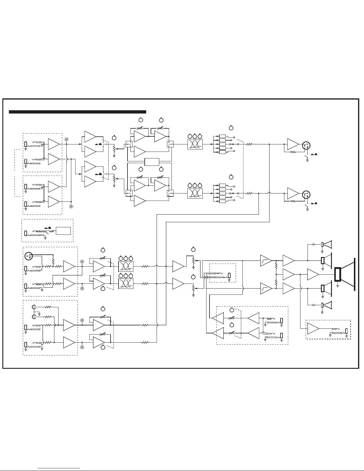
Input 1
Input 2
Input 2
Channel 1
Channel 2
Footswitch
Front Panel
Drive Switch
Channel 3
Block Diagram for Keymaster K4
DESIGNED & MANUFA CTURED BY YORKVILLE SOUND
EQ
Bass/Mid/Hi
Bass/Mid/Hi
L
R
L
L
R
L
R
L
L
R
R
L
R
Input 2
RCA
Input
In L/Mono
Tube
Gain
Tube/Solid State
Switch
Solid
State
Tube
Solid
State
In R
CLIP 1
CLIP 2
CLIP 1
CLIP 2
CLIP 3
CLIP 3
Line Out L
L Bus
GND Lift
R Bus
Gain
Master L
Master R
HP
L Tweeter
Woofer
R Tweeter
L Mid
R Mid
HP
L Amp
LF Amp
R Amp
Ch 4 Gain L
Ch 4 Gain L
Gain L
Gain R
1
2
3
4
5
EQ
EQ L
EQ R
Voicing Select R
Voicing Select L
1
2
3
4
5
L Bus
R Bus
L Bus
R Bus
Channel 4 (Monitor Channel)
Sub Out
Headphone
T=Left/R=Right/S=Gnd
Solid State
Tube Gain Trim L
R
Line Out R
GND Lift
Solid State
Tube Gain Trim R
Lead Gain R
Lead Gain L
Gain L
Gain R
In L/Mono
In R
In L/Mono
In R
OD Enable
Circuit
In L/Mono
In R
XLR
Mic In
In L/Mono
In R
OD Enable
Circuit
BLOCK-DIAG-K4-00-1v1.ai
MODEL TYPE: YS1045
w w w . yo r k v i l l e . c o m
REAL Gear.
REAL People.
Yorkville Sound
550 Granite Court
Pickering, Ontario
L1W-3Y8 CANADA
Canada
Voice: (905) 837-8481
Fax: (905) 837-8746
Yorkville Sound Inc.
4625 Witmer Industrial Estate
Niagara Falls, New York
14305 USA
U.S.A.
Voice: (716) 297-2920
Fax: (716) 297-3689
SERVICE BULLETIN
Amp Cover
Lid Screws (20)
Tube retaining bracket
Tube retaining
bracket screws (2)
K4 Amplifier
Tubes
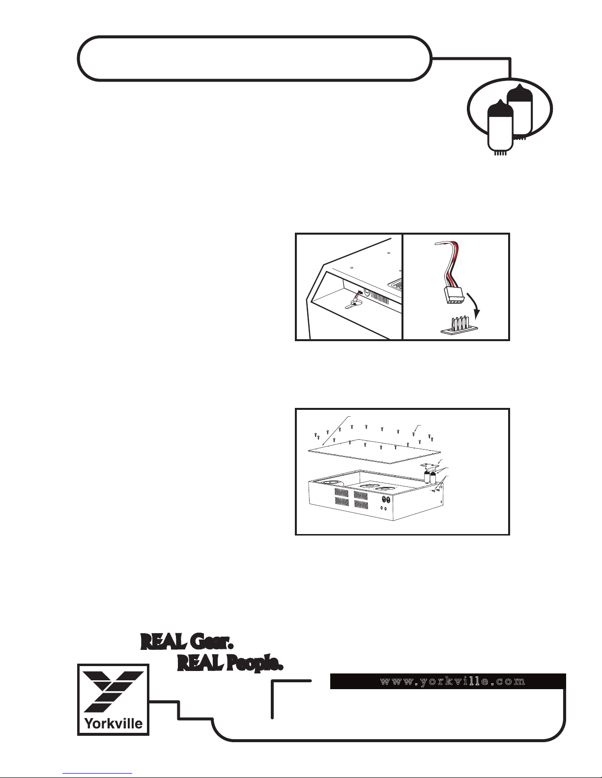
K4 Pre-amp Tube Replacement
The Two 12AX7A/7025A tubes are inside the chassis.
To remove the chassis from the cabinet follow these instructions.
1. Unplug all connections. Make sure the K4 is unplugged from the AC main line and
remove all instrument and other cable connections.
2. Remove K4 Chassis from cabinet. Before removing K4 chassis from speaker
cabinet, make sure to unplug the speaker connectors.
a) Remove the five top bolts and loosen the vent screws holding the k4 chassis to the
cabinet; this will enable you to push the chassis forward approximately 2 inches until the
speaker wire connections at the
rear left will be visible.
b) Disconnect the connecter while
noting the orientation of the
locking fingers for when you reconnect them after the tubes
have been changed. Continue
pushing the chassis forward until
it is out of the cabinet.
If the chassis snags on the
cabinet vinyl, reverse the process
and push it out the back of the cabinet. You may find it worthwhile to insert thin strips
of plastic as shims between the chassis and cabinet down the sides to reduce the
chance of snagging.
5. Once the chassis is removed, using
a small Phillips screwdriver, remove the
20 screws that are used to mount the
amplifier lid. You will find the tubes near
the front of the chassis on the left side
(looking from the front). They are held in
place with a retaining bracket which needs
to be unscrewed and removed before you
pull the 12AX7/7025s out of their sockets.
Remove the tube-retainer bracket screws,
and pull the bracket upward. Proceed to
replace the two 12AX7A/7025A tubes.
6. Reinstall the tube bracket and chassis lid screws.
7. Slide the chassis carefully back into the cabinet remembering to clear the speaker wires;
don’t forget to reconnect the speaker wires before sliding the unit into its final position.
8. Reinstall the large retaining bolts and tighten-down the vent plate screws.
Speaker Connection
Lid and Tube Retaining Bracket
1
w w w . yo r k v i l l e . c o m
REAL Gear.
REAL People.
Yorkville Sound
550 Granite Court
Pickering, Ontario
L1W-3Y8 CANADA
Canada
Voice: (905) 837-8481
Fax: (905) 837-8746
Yorkville Sound Inc.
4625 Witmer Industrial Estate
Niagara Falls, New York
14305 USA
U.S.A.
Voice: (716) 297-2920
Fax: (716) 297-3689
SERVICE BULLETIN
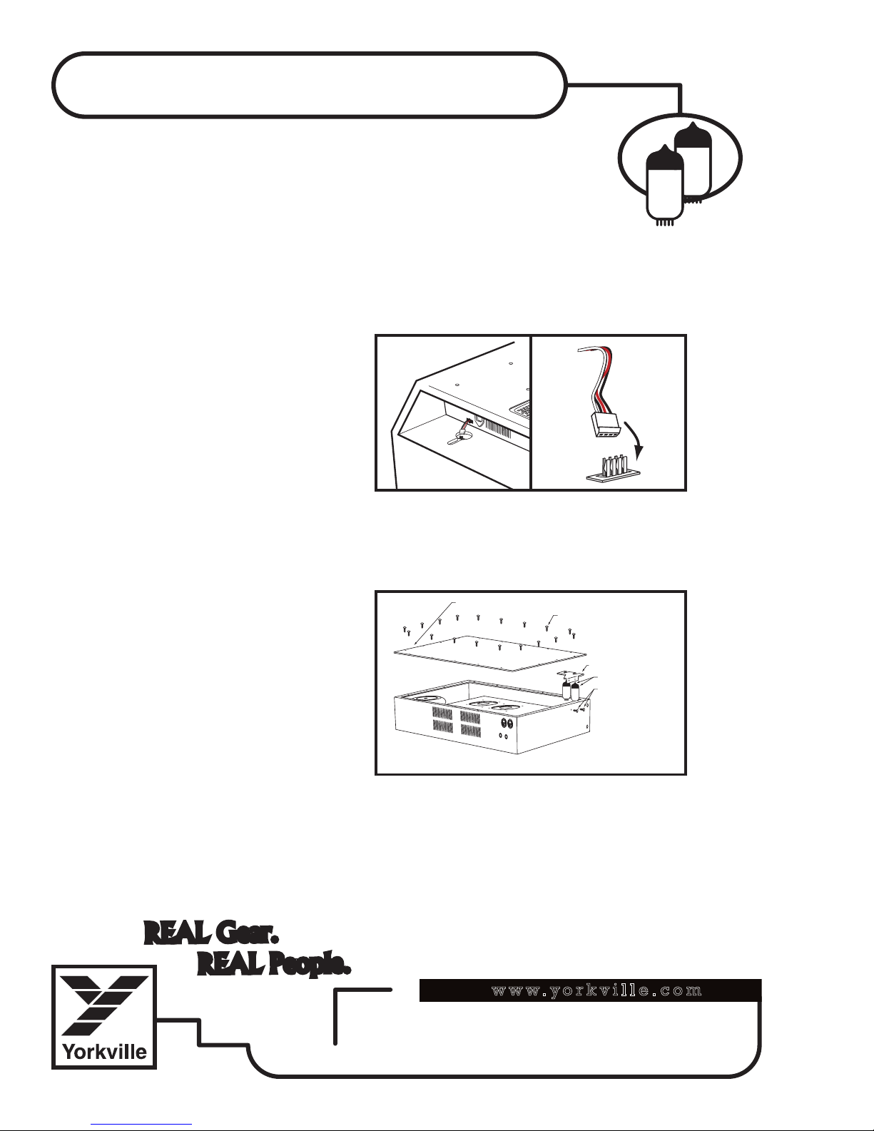
Remplacement des Lampes Pour le
Amp Cover
Lid Screws (20)
Tube retaining bracket
Tube retaining
bracket screws (2)
K4 Amplifier
Tubes
Préamplificateur K4
Les deux lampes 12AX7A/7025A sont à l’intérieur du châssis.
Pour retirer le châssis de l’enceinte suivez les instructions ci-dessous.
1. Débranchez toutes les connexions. Assurez-vous que le K4 est débranché du
circuit CA et débranchez tous les autres câbles incluant les instruments.
2. Assurez-vous aussi de débrancher le connecteur du haut-parleur, et retirer ensuite le
châssis de l’enceinte.
a) Enlevez les cinq boulons du dessus et desserrer les vis de la plaque d’évent
qui tiennent le châssis à l’enceinte; cela vous permettra de pousser le châssis vers
l’avant d’environ 2 pouces jusqu’à
ce que les connexions du câble de
raccordement pour haut-parleur à
l’arrière gauche soient visibles.
b) Débranchez le connecteur en
prenant note de l’orientation du
joint de verrouillage pour raccorder
correctement le connecteur
une fois les lampes changées.
Continuez ensuite de pousser le
châssis vers l’avant jusqu’à ce
qu’il soit sortie de l’enceinte.
Si en le sortant par l’avant, le châssis se trouve coincé sur le vinyle de l’enceinte,
renversez le processus et poussez-le vers l’arrière de l’enceinte. Vous trouverez peutêtre préférable d’insérer de minces bandes de plastique comme cale entre le châssis
et le cabinet pour réduire les chances d’accrochage.
5. Une fois le châssis enlevé, à l’aide d’un
petit tournevis de type Phillips, enlevez
les 20 vis utilisées pour fixer le couvercle
au châssis. Les lampes sont situées près
du devant du châssis sur le côté gauche
(vue du devant). Elles tiennent en place à
l’aide d’une fixation qui doit être dévissée
et enlevée avant que vous puissiez tirer les
12AX7/7025 de leur douille. Enlevez les
vis des fixations et tirez les fixations vers le
haut. Procédez au remplacement des deux
lampes 12AX7A/7025A.
6. Réinstallez les fixations et le couvercle
du châssis à l’aide des vis fournies.
7. Glissez avec prudence le châssis dans l’enceinte en gardant les fils de haut-parleur
accessibles; n’oubliez pas de reconnecter les fils de haut-parleur avant de glisser l’appareil
jusqu’à sa position finale.
8. Réinstallez les gros boulons et resserrez les vis de la plaque d’évent.
Speaker Connection
Lid and Tube Retaining Bracket
2
SERVICE BULLETIN
January 29, 2009
K
E
Y
M
A
S
T
E
R
k4k4
The K4 is a powerful 300-Watt compact and light-weight combo
amplifier for keyboards. The product houses 5 drivers in it's speaker section and a chassis that has 3 amplifiers, a set of tubes, 2
fans (with heat sinks) and 6 circuit boards. All of these components potentially rattle and/or buzz at various frequencies. Yorkville
uses a specific method to help prevent the sound energy from
being transferred from to the speaker compartment to the chassis.
Yorkville has taken great care by using dampening foam inside
to help reduce a great deal of rattling. Special foam and rubber
washers are also used for mounting the chassis to the cabinet.
The top 5 chassis mounting bolts are not fully tightened, this helps
prevent the transference of the sound energy to the chassis from
the speakers.
Over tightening the top 5 bolts may result in rattle and buzz!
If chassis is removed and replaced, we recommend using a
Phillips head screw driver and tighten each bolt so that the top of
the head is just above the surface of the cabinet. To test if the
mounting is done correctly, apply a little force to the front and then
the back of the chassis if it moves too much, retighten the bolts
and redo the test again.
1
 Loading...