

York Fitness PACER 480 HRC Instruction Manual
PACER
A
PL TINUM
INSTRUCTION
INSTRUCTION
MANUAL
MANUAL
e
r
Se i s
48O
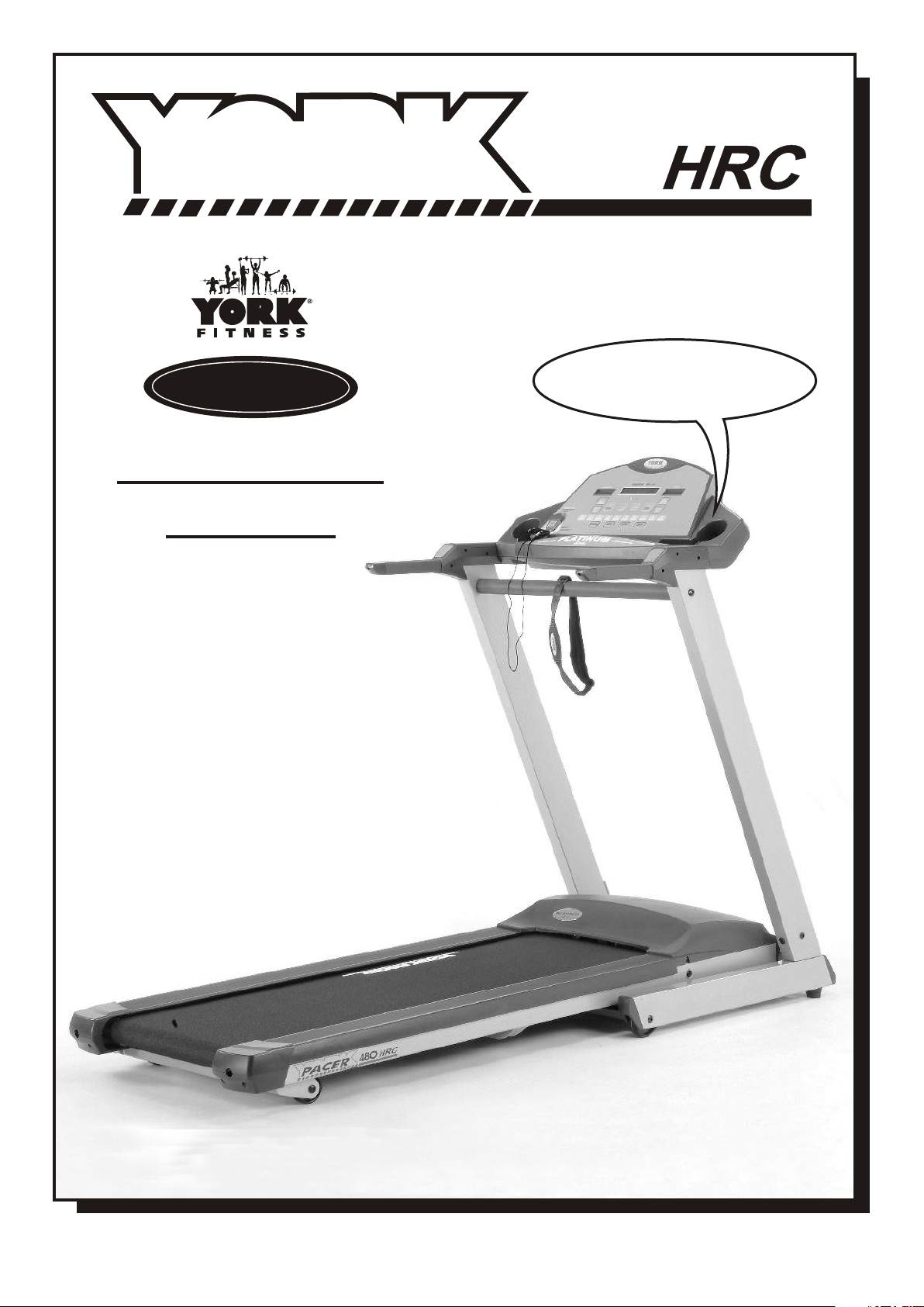
An electronic voice
guides you through setting
the treadmill computer
01 / 2004 TWN
Product may vary slightly from the item pictured.
COMPLIES WITH EUROPEAN STANDARD EN957 PT 1+6 CLASS H C

YORK PACER 480HRC TREADMILL
SAFETY GUIDELINES:
Please read and follow the safety guidelines:
Before beginning any exercise program, you should consult with your doctor.
It is recommended that you undergo a complete physical examination.
Read this owner’s manual and follow the instructions.
Assemble and operate the YORK PACER 480HRC on a solid, level surface.
Keep the area behind the YORK PACER 480HRC clear.
Always allow a clear space measuring 1m wide and 2m long immediately behind
the YORK PACER 480HRC.
The treadmill will not operate without the safety key.
Never allow children on or near the treadmill.
The treadmill running mat will not stop immediately if any object becomes caught in the
mat or rollers - IN EMERGENCY: Pull the safety key cord to remove safety key.
Always check the treadmill before using it.
Make sure all parts are assembled, and nuts and bolts are tight.
Do not use the treadmill if the unit is disassembled in any way.
Keep hands away from moving parts.
The weight limit for this treadmill is 275 lbs (125 kgs).
Wear proper workout clothing: Do not wear loose clothing.
Do not wear shoes with leather soles or high heels. Tie all long hair back.
Don’t rock the unit from side to side.
Care should be taken when mounting and dismounting the unit.
Do not place any liquids on any part of the treadmill.
To prevent shock, keep all electrical components, such as the motor, cable and switch away
from water.
Do not use any accessories that aren’t specifically recommended by the manufacturer,
these might cause injuries or cause the unit to fail.
Work within your recommended exercise level, do NOT work to exhaustion.
If you feel any pain or abnormal symptom, STOP YOUR WORKOUT IMMEDIATELY.
Consult your physician immediately.
Turn off the treadmill while adjusting or working near the rear roller.
TAKE CARE TO PROTECT CARPETS AND FLOOR in case of leakages. This product is a
TAKE CARE TO PROTECT CARPETS AND FLOOR
machine and contains moving parts which have been greased / lubricated and could leak.
WARNING - This appliance must be EARTHED.---IMPORTANT
The YORK PACER 480HRC is designed for the use and enjoyment of the serious trainer as well as
the dedicated user. By following the above precautions and using good judgement and common
sense, you will have a safe and pleasurable exercise regimen with the YORK PACER 480HRC.
TOOLS REQUIRED - The tool enclosed in the carton is one allen key.
SHOULD YOU REQUIRE ANY ASSISTANCE REGARDING THIS PRODUCT PLEASE CONTACT YORK DIRECTLY.
U.K.
HELP LINE (8:30am- 4:30pm)
YORK BARBELL (U.K.) LTD.
CHURCHILL WAY, DAVENTRY,
NORTHANTS, NN11 4YB ENGLAND
TEL: (01327) 701-824
FAX: (01327) 706-704
E-MAIL: helpdesk@yorkfitness.co.uk
PACER 480HRC TM / 01
AUSTRALIA
HELP LINE (8:00am- 4:00pm)
YORK BARBELL (AUST.) LTD.
UNIT 1, LOT 2, SWAFFHAM ROAD,
MINTO, N.S.W. 2566 AUSTRALIA
TEL: (02) 9603-8444
FAX: (02) 9603-8555
E-MAIL: heatheryork@ozemail.com.au
BERNSPORT (1995) LTD.
PO BOX 33-973 TAKAPUNA,
AUCKLAND NEW ZEALAND.
E-MAIL: sales@bernsport.co.nz
N.Z.
HELP LINE (8:30am- 4:30pm)
TEL: +64-9-488-4750
FAX: +64-9-488-4759
INTRODUCTION
The YORK PACER 480HRC TREADMILL has been designed and constructed to provide trouble
free usage and enjoyable exercise. You can greatly improve your understanding of the benefits
of exercising by carefully reading the instructions given in this manual.
Please familiarize yourself with the maintenance advice provided for you.
SPECIFICATIONS
POWER SUPPLY: 220~240V 50Hz
SPEED CONTROL : PUSH BUTTON
ELEVATION: POWER INCLINE 0%~10%
SPEED RANGE: 1 ~ 16 KPH
CLASS HC: Domestic Use / Minimum Accuracy
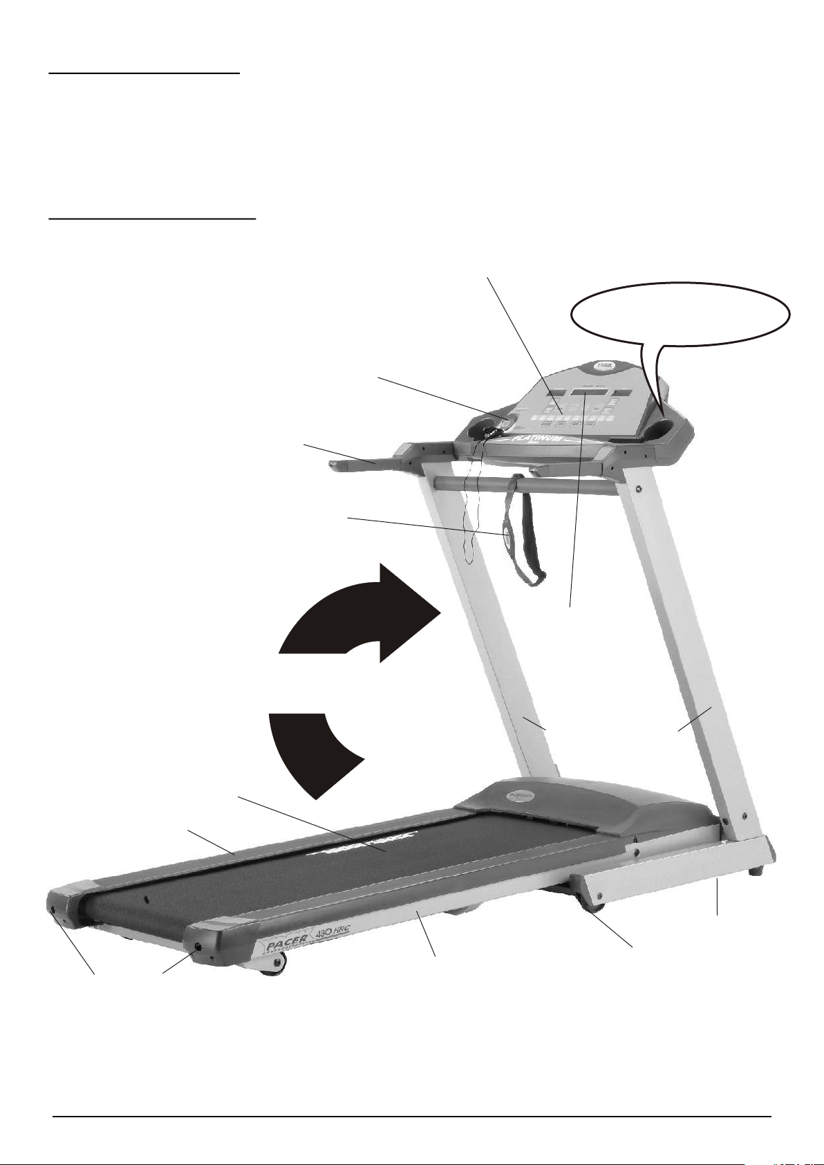
SAFETY KEY
HANDLE BAR WITH FOAM GRIP
TELEMETER SENSOR
10 PROGRAMS - USER A, USER B,
SPEED INTERVAL, AEROBIC, WEIGHT LOSS,
HILL CLIMB, HR CONTROL, TARGET: TIME,
TARGET: DIST. & TARGET: CAL.
An electronic voice
guides you through setting
the treadmill computer
RUNNING MAT
NON SLIP FOOTPAD
BELT ADJUSTING BOLTS-ADJUST BELT TENSION &
TO CENTRALIZE MAT
FOLD TREADMILL UP AND STAND
VERTICALLY FOR STORAGE
MAIN FRAME
COMPUTER SHOWS
ELEVATION, TIME,
CALORIE / PULSE,
DISTANCE, SPEED &
MAX. HEART RATE
HANDLE BAR POST
FOUR WHEELS
TRANSPORTATION
SYSTEM ALLOWS
YOU TO MOVE
THE TREADMILL
EASILY WHEN
FOLDED
SHOULD YOU REQUIRE ANY ASSISTANCE REGARDING THIS PRODUCT PLEASE CONTACT YORK DIRECTLY.
*
PACER 480HRC TM / 02
*
GENERAL
WE RECOMMEND YOU HAVE SOMEONE ASSIST YOU IN LIFTING AND
ASSEMBLING YOUR PACER 480HRC TREADMILL.
FOLLOW THESE INSTRUCTIONS CAREFULLY AND IT WILL MAKE IT EASIER
FOR YOU TO ASSEMBLE YOUR PACER 480HRC TREADMILL.
ASSEMBLY INSTRUCTIONS
1.
Product may vary slightly from the item pictured.
Ask someone to help you remove all the parts and packaging materials on the top of your
YORK PACER 480HRC from the carton and place them on the floor carefully.
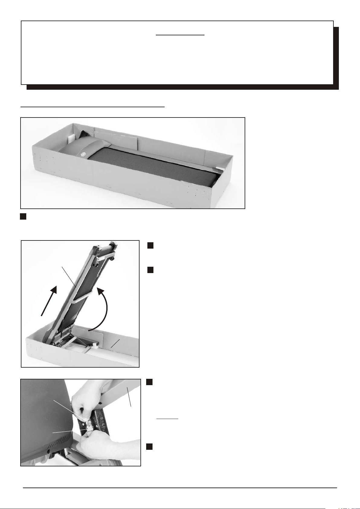
2.
Fold the main frame up and stand it in the base carton
MAIN
FRAME
2.
1.
BASE
CARTON
as shown.
Ask someone to help you hold the treadmill on each
side and lift it out from the base carton carefully.
3.
Rest the left handle bar post on your shoulder
MIDDLE
WIRE PLUG
LEFT
HANDLE
BAR
POST
SENSOR
WIRE SOCKET
and hold the bottom end close to the handle bar
mounting tube as shown.
NOTE: We recommend you ask someone to connect
the cables for you while you hold the handle bar
post.
Connect the sensor wire socket to the middle
wire plug protruding at the base of the left
handle bar post.
SHOULD YOU REQUIRE ANY ASSISTANCE REGARDING THIS PRODUCT PLEASE CONTACT YORK DIRECTLY.
*
PACER 480HRC TM / 03
*
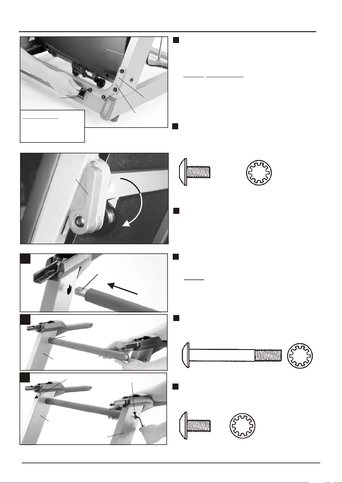
NOTE: DO NOT FULLY TIGHTEN THE BOLTS UNTIL YOU HAVE COMPLETED THE ASSEMBLY.NOTE: DO NOT FULLY TIGHTEN THE BOLTS UNTIL YOU HAVE COMPLETED THE ASSEMBLY.
4.
BASE FRAME
TAKE CARE
- DO NOT TRAP CABLE.
- DO NOT FULLY
TIGHTEN BOLTS YET.
5.
LOCK
HANDLE
LEFT HANDLE
BAR POST
FLAT
SIDE
FIXING
BRACKET
Insert the left handle bar post into the handle
bar post mounting tube and secure the fixing
bracket onto the base frame, using six allen
head bolts and star washers.
NOTE: TAKE CARE to ensure the cable does
not get trapped when you attach the
left handle bar post.
The flat side of the fixing bracket
must be attached on the handle bar
post as shown.
Insert the right handle bar post into the
handle bar post mounting tube and secure
the fixing bracket onto the base frame, using
six allen head bolts and star washers.
X12
#8563-93
#8563-09
6.
A.
B.
C.
HANDLE BAR PROTRUDES
INSERT THIS END FIRST
RIGHT
HANDLE BAR POST
SHORT BOLT
Release the lock handle fitted on the rear
left side of the main frame with your left
hand and fold down the main frame to the
floor gently by your right hand.
Insert the handle bar into the handle bar post
as shown.
NOTE: One end of the handle bar protrudes
from the end of the foam grip, this
end must be inserted into the hole on
the right handle bar post first.
Secure the handle bar to the left handle bar
post by using, one long allen head bolt and
star washer.
X1
#8563-102 #8563-09
LONG BOLT
Secure the handle bar to the right handle bar
post by using, one short allen head bolt and
star washer.
RIGHT HANDLE
BAR POST
LEFT HANDLE
BAR POST
SHOULD YOU REQUIRE ANY ASSISTANCE REGARDING THIS PRODUCT PLEASE CONTACT YORK DIRECTLY.
*
#8563-93
#8563-09
PACER 480HRC TM / 04
X1
*
7.
MIDDLE WIRE
SOCKET
8.
HANDLE BAR POST
MOUNTING TUBE
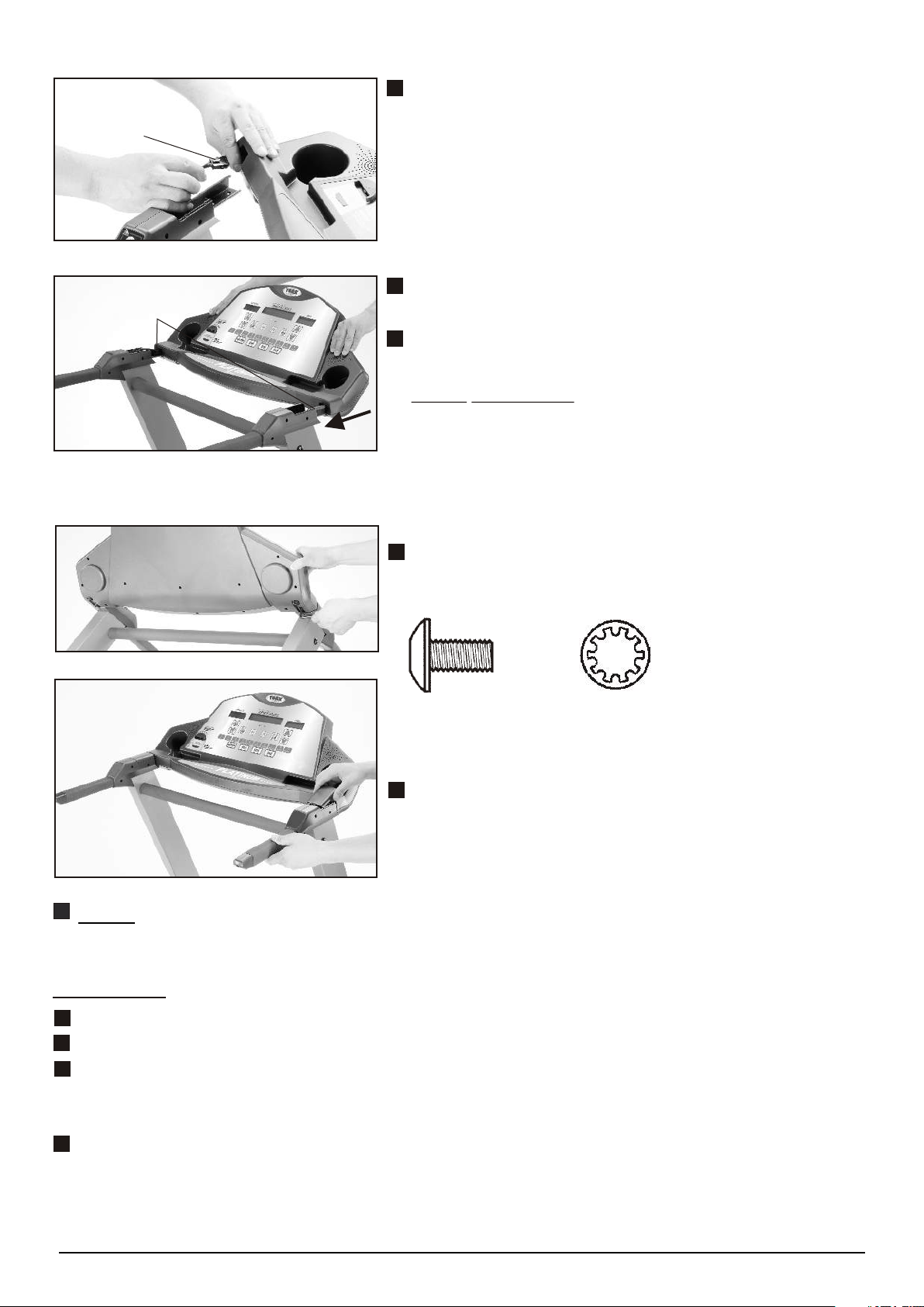
9.
Rest the computer console on the front handle bar
and connect the computer wire plug to the middle
wire socket protruding at the top of the left handle bar
post securely.
Attach the computer console fully onto the handle
bar post mounting tubes carefully as shown.
Push the extra length of wire down into the
handle bar post gently while attaching the console.
NOTE: TAKE CARE to ensure the wire does
not get trapped when you attach the
computer console.
If the console will not align and fit
easily, loosen all the bolts fitted so far and try again.
Secure the computer console to the handle bar post
mounting tubes by using, four allen head bolts and
star washers.
10.
#8563-93
Attach the handle bar post top covers onto the handle
bar properly as shown.
NOW tighten all the bolts you have fitted.NOW tighten all the bolts you have fitted.
RECHECK
X4
#8563-09
Recheck that all of the bolts are tightened securely for your safety and comfort.
Plug the power cable into a suitable AC outlet (220~240 Volt 50Hz).
Before you use the treadmill for the first time turn on the power switch and connect the
magnetic safety key.
Allow the treadmill to run for 10 minutes or so without anyone using it.
Check that the mat is tightened properly and runs smoothly.
SHOULD YOU REQUIRE ANY ASSISTANCE REGARDING THIS PRODUCT PLEASE CONTACT YORK DIRECTLY.
*
PACER 480HRC TM / 05
*
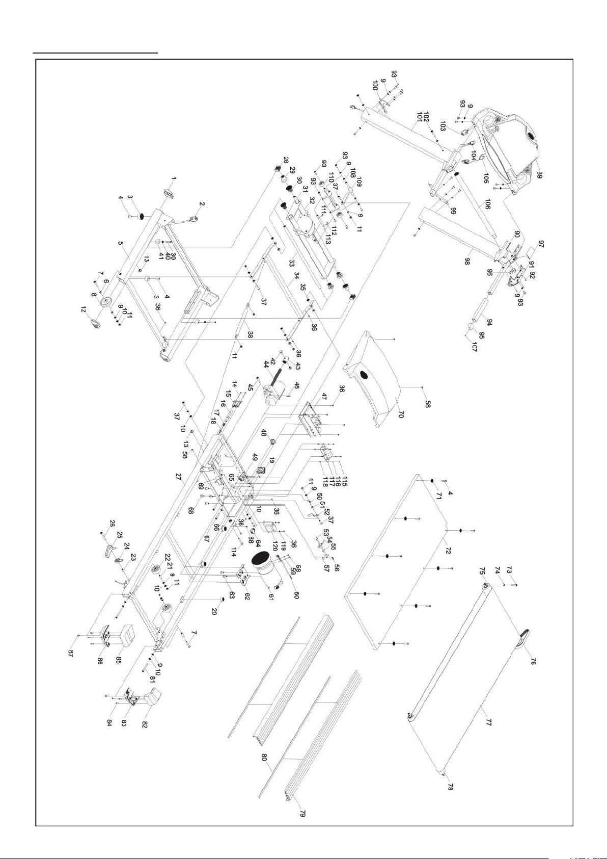
DESCRIPTION
PACER 480HRC TM / 06

PARTS LIST
52 8563-52 1 OFF POWER BRACKET
53 8563-53 2 M3 X 15mm PHILLIPS HEAD SCREW
54 8563-54 1 MICRO SWITCH
55 8563-55 1 INSULATION BRACKET
56 8563-56 2 M4 X 8mm MACHINE SCREW
57 8563-57 1 MICRO SWITCH BRACKET
58 8563-58 6 M5 X 10mm MACHINE SCREW
59 8563-59 2 M5 X 1.3mm SPRING WASHER
60 8563-60 1 SPEED SENSOR W / CABLE / 580mm LONG
KEY NO. PART NO. Q'TY(PCS) DESCRIPTION
1 8563-01 2 BASE FRAME END CAP ( FRONT )
2 8563-02 1 CONTROLLER SIGNAL CABLE / 1250mm LONG
3 8563-03 4 PVC FOOT STOP
4 8563-04 12 M6 X 25mm MACHINE SCREW
5 8563-05 1 BASE FRAME-WELDED
6 8563-06 4 MOVING WHEEL SLEEVE
7 8563-07 3 M8 X 50mm ALLEN HEAD BOLT
8 8563-08 2 BASE FRAME MOVING WHEEL
9 8563-09 28 M8 X 0.8mm STAR WASHER
10 8563-10 10 M8 X 1.6mm FLAT WASHER
11 8563-11 10 M8 X 7.8mm NYLON LOCKNUT
12 8563-12 2 MOVING WHEEL END CAP
13 8563-13 3 SNAP BUSHING
14 8563-14 2 M5 X 40mm SOCKET HEAD SCREW
15 8563-15 1 LOCK PIN CAP ( L )
16 8563-16 1 LOCK PIN
17 8563-17 1 LOCK PIN SPRING
18 8563-18 1 LOCK RELEASE CABLE
19 8563-19 1 MAIN FRAME END CAP ( FRONT )
20 8563-20 6 RUNNING DECK CUSHION PAD
21 8563-21 2 REAR MOVING WHEEL SLEEVE
22 8563-22 2 REAR MOVING WHEEL
23 8563-23 1 LOCK HANDLE SLEEVE
24 8563-24 1 LOCK RELEASE LEVER
25 8563-25 1 LOCK RELEASE HANDLE
26 8563-26 1 ALLEN HEAD BOLT
27 8563-27 1 MAIN FRAME - WELDED
28 8563-28 2 TRACK SLIDER
29 8563-29 2 BUSHING SPACER
30 8563-30 4 CONNECT TUBE BUSHING
31 8563-31 1 INCLINE PIVOT SHAFT
32 8563-32 1 INCLINE MECHANISM-WELDED
33 8563-33 1 INCLINE FIXED SHAFT
34 8563-34 1 H FRAME SUPPORT - WELDED
35 8563-35 8 CONNECT METAL BUSHING
36 8563-36 16 M4 X 8mm MACHINE SCREW
37 8563-37 6 M8 X 30mm ALLEN HEAD BOLT
38 8563-38 1 GAS CYLINDER
39 8563-39 2 M6 X 40mm HEX HEAD SCREW
40 8563-40 2 M6 X 0.6mm STAR WASHER
41 8563-41 2 TRACK STOPPER
42 8563-42 2 INCLINE MOTOR FIXING SCREW
43 8563-43 1 INCLINE MOTOR NUT
44 8563-44 1 INCLINE MOTOR
45 8563-45 1 INCLINE MOTOR FIXING PIN
46 8563-46 1 R PIN
47 8563-47 1 LOWER CONTROLLER ASSY
48 8563-48 1 ON / OFF POWER SWITCH
49 8563-49 1 AC INLET SOCKET
50 8563-50 1 OFF POWER SPRING
51 8563-51 1 OFF POWER SLEEVE
PACER 480HRC TM / 07

KEY NO. PART NO. Q'TY (PCS) DESCRIPTION
61 8563-61 1 D.C. MOTOR
62 8563-62 1 MOTOR BRACKET - WELDED
63 8563-63 2 M8 X 20mm HEX HEAD BOLT
64 8563-64 1 CIRCUIT BREAKER
65 8563-65 2 M4 X 6mm MACHINE SCREW
66 8563-66 1 M8 X 6.5mm HEX NUT
67 8563-67 2 M8 X 50mm HEX HEAD BOLT
68 8563-68 4 M8 X 20mm FRINGE HEAD BOLT
69 8563-69 1 CAPACITOR
70 8563-70 1 MOTOR COVER
71 8563-71 8 SIDE LANDING WASHER
72 8563-72 1 RUNNING DECK
73 8563-73 1 M8 X 30mm HEX HEAD BOLT
74 8563-74 1 CURVE WASHER
75 8563-75 1 FRONT ROLLER ASSY
76 8563-76 1 DRIVER BELT - RIBBED
77 8563-77 1 RUNNING MAT
78 8563-78 1 REAR ROLLER ASSY
79 8563-79 2 FOOT PLATFORM
80 8563-80 2 SINGLE -BACK SPONGE RUBBER
81 8563-81 2 M8 X 65mm HEX HEAD BOLT
82 8563-82 1 REAR END CAP TOP ( R )
83 8563-83 1 REAR END CAP BOTTOM ( R )
84 8563-84 6 M4 X 20mm MACHINE SCREW
85
8563-85
1 REAR END CAP TOP ( L )
86
8563-86
1 REAR END CAP BOTTOM ( L )
87
8563-87
2 M6 X 10mm MACHINE SCREW
88
8563-88
2 M4 X 15mm MACHINE SCREW
89
8563-89
1 COMPUTER CONSOLE
90
8563-90
2 HANDLE BAR LEFT SIDE COVER
91
8563-91
2 HANDLE BAR RIGHT SIDE COVER
92
8563-92
6 M3 X 15mm PHILLIPS HEAD SCREW
93
8563-93
23 M8 X 15mm ALLEN HEAD BOLT
94
8563-94
2 HANDLE BAR FOAM GRIP
95 8563-95 2 HANDLE BAR END CAP
96 8563-96 2 HANDLE PCB COVER
97 8563-97 2 HANDLE BAR TOP COVER
98 8563-98 1 HANDLE BAR POST ( R )
99 8563-99 1 HANDLE BAR POST FIXING BRACKET ( R )
100 8563-100 1 HANDLE BAR POST FIXING BRACKET ( L )
101 8563-101 1 HANDLE BAR POST ( L )
102 8563-102 1 M8 X 55mm ALLEN HEAD BOLT
103 8563-103 1 COMPUTER CABLE / 550mm LONG
104 8563-104 1 MIDDLE WIRE / 1400mm LONG
105 8563-105 1 SAFETY KEY
106 8563-106 1 FRONT HANDLE BAR
107 8563-107 2 M3 X 10mm PHILLIPS HEAD SCREW
108 8563-108 2 LINKAGE SUPPORT SLEEVE
109 8563-109 1 INCLINE SUPPORT LINKAGE - WELDED
110 8563-110 2 INCLINE MOVING WHEEL
111
8563-111
1 INCLINE WHEEL LINKAGE - WELDED
112
8563-112
2 E-RING
113 8563-113 1 INCLINE LINKAGE SHAFT
114 8563-114 1 M8 X 40mm HEX HEAD BOLT
115 8563-115 4 M3 X 6mm PHILLIPS HEAD SCREW
116 8563-116 4 M3 X 0.8mm SPRING WASHER
117 8563-117 1 EMI FILTER
118 8563-118 4 CU SCREW SLEEVE
119 8563-119 2 M4 X 0.45mm STAR WASHER
120 8563-120 1 CHOKE
PACER 480HRC TM / 08

OPERATING INSTRUCTIONS
The following procedure has been proven to be the safest and easiest method of mounting
the treadmill.
For your protection, carefully read and follow these simple steps:
1. Be sure the treadmill is positioned on a flat, level surface.
2. Make sure the magnetic safety key is not attached then plug in the treadmill power cable to a
suitable power socket and switch on at the socket.
3. Turn on treadmill power switch, which is located near where the power cable attaches to the
treadmill.
4. Straddle the running mat with your feet firmly planted on the right and left foot pads.
Stand close enough so you can extend your arms to touch all the buttons on the console.
CAUTION: Do not stand on the mat yet.
5. Insert the safety key.
6. Follow the instructions written on bottom of computer console” TO OPERATE “
( An electronic voice guides you through setting the treadmill computer )
STARTING YOUR EXERCISE
STARTING YOUR EXERCISE
Stand on the running mat.
Once you have selected your workout, the treadmill will slowly increase it’s speed to
the desired levels.
Continue to grip the handles until you are walking / running normally.
After gaining stability and confidence, release your grip on the handrails and let your arms
swing freely and naturally at your side.
TO OPERATE
NOTE: Walking straight on the treadmill is aided by focussing on a stationary object across
the room in front of you.
Walk as if you were approaching that object.
N AN EMERGENCY
In an emergency take hold of the handrails and place your feet on the side rails provided,
once you are stable, pull out the safety key. The treadmill will then begin to decelerate
until it stops.
SHOULD YOU REQUIRE ANY ASSISTANCE REGARDING THIS PRODUCT PLEASE CONTACT YORK DIRECTLY.
*
PACER 480HRC TM / 09
*
 Loading...