

Page 1
PACKAGED ROOFTOP
AIR CONDITIONING UNITS
INSTALLATION, OPERATION & MAIN TE NANCE
SIMPLICITY ELITE CONTROL
New Release
YPAL 050
YPAL 051
YPAL 060
YPAL 061
DESIGN LEVEL F
Form 100.50-NOM6 (1207)
035-21979-002
LD13271
Page 2
IMPORTANT!
READ BEFORE PROCEEDING!
GENERAL SAFETY GUIDELINES
FORM 100.50-NOM6 (1207)
This equipment is a relatively complicated ap pa ra tus.
Dur ing installation, operation, maintenance or service,
in di vid u als may be exposed to certain com po nents or
conditions in clud ing, but not limited to: re frig er ants,
oils, materials un der pressure, rotating com po nents,
and both high and low voltage. Each of these items
has the po ten tial, if misused or handled im prop er ly, to
cause bodi ly injury or death. It is the obligation and
re spon si bil i ty of operating/service per son nel to iden ti fy
and rec og nize these inherent hazards, protect them selves,
and pro ceed safely in completing their tasks. Failure to
com ply with any of these requirements could re sult in
se ri ous dam age to the equipment and the prop er ty in
which it is sit u at ed, as well as severe personal injury or
death to them selves and people at the site.
This document is intended for use by owner-authorized
operating/service personnel. It is expected that this
in di vid u al possesses independent training that will
en able them to perform their assigned tasks properly
and safe ly. It is essential that, prior to performing any
task on this equipment, this individual will have read
and un der stood this document and any referenced
materials. This in di vid u al will also be familiar with and
comply with all ap pli ca ble governmental standards and
regulations per tain ing to the task in question.
SAFETY SYMBOLS
The following symbols are used in this document to alert the reader to areas of potential hazard:
DANGER indicates an im mi nent ly
hazardous situation which, if not
avoid ed, will re sult in death or se ri ous
injury.
CAUTION identifi es a hazard which
could lead to damage to the ma chine,
damage to other equip ment and/or
en vi ron men tal pollution. Usually an
in struc tion will be given, together with
a brief ex pla na tion.
WARNING indicates a potentially
haz ard ous sit u a tion which, if not
avoid ed, could result in death or se-
NOTE is used to highlight ad di tion al
information which may be helpful to
you.
ri ous in ju ry.
External wiring, unless specifi ed as an optional connection in the man u fac tur er’s prod uct
line, is NOT to be connected inside the micro pan el cab i net. De vic es such as re lays, switch es,
transducers and controls may NOT be installed inside the mi cro pan el. NO external wiring
is al lowed to be run through the micro panel. All wir ing must be in ac cor dance with JOHNSON CONTROLS’s pub lished spec i fi ca tions and must be per formed ONLY by qual i fi ed
JOHNSON CONTROLS personnel. JOHNSON CONTROLS will not be re spon si ble for
dam ag es/problems re sult ing from im prop er con nec tions to the con trols or ap pli ca tion of
im prop er con trol sig nals. Failure to fol low this will void the man u fac tur er’s warranty and
cause serious dam age to property or injury to per sons.
2
JOHNSON CONTROLS
Page 3

CHANGEABILITY OF THIS DOCUMENT
d
P
d
P
FORM 100.50-NOM6 (1207)
In complying with JOHNSON CONTROLS’s policy
for continuous prod uct improvement, the in for ma tion
con tained in this doc u ment is subject to change without
notice. While JOHNSON CONTROLS makes no
com mit ment to update or provide current in for ma tion
au to mat i cal ly to the manual owner, that in for ma tion, if
ap pli ca ble, can be ob tained by con tact ing the nearest
JOHNSON CONTROLS Applied Systems offi ce.
It is the responsibility of operating/service personnel
to verify the ap pli ca bil i ty of these doc u ments to the
equip ment in question. If there is any question in
the mind of operating/service personnel as to the
applicability of these doc u ments, then prior to work ing
on the equip ment, they should verify with the owner
whether the equip ment has been modifi ed and if current
literature is avail able.
NOMENCLATURE
BASE MODEL NUMBER
YPAL050-061
1 2 3 4 5 6 7 8 9 10 11 12 13 14 15 16
Base Type Refrigerant Supply
Product Nominal Capacity Application
Y :YORK 5 0 :50 Ton Capacity :208/3/60
P :Packaged Rooftop 0 5 1 :51 Ton Capacity C :R-22 :230/3/60
A :Air Cooled 0 6 0 :60 Ton Capacity E :R-410A 4 6 :460/3/60
L :Scroll 0 6 1 :61 Ton Capacity 5 8 :575/3/60
0 B :R-407C
C :Constant Volume
V :VAV, VFD
F :Flexsys
C :Cooling Only
N :Staged Natural Gas Heat
G :Staged Natural Gas Heat SS HX
M :Full Modulating Gas Heat
F :Full Modulating Gas Heat SS Staged HX
E :Electric Heat
H :Hot Water Heat
S :Steam Heat
Voltage
25
4 0 :380/3/60
4 5 :400/3/50
Openings
B :Bottom Supply
L :Left Supply
R :Right Supply
Return
Openings
B :Bottom Return
R :Rear Return
S :Side Return
Design Special
X :Standar
S :Special
A :Standar
B :Special
F :Revision Level F
LD13270
JOHNSON CONTROLS
3
Page 4

FORM 100.50-NOM6 (1207)
TABLE OF CONTENTS
BASE MODEL NUMBER ..............................................................................................................................3
CHANGEABILITY OF THIS DOCUMENT .....................................................................................................3
NOMENCLATURE .........................................................................................................................................3
TABLE OF CONTENTS ................................................................................................................................4
LIST OF TABLES ........................................................................................................................................ 11
LIST OF FIGURES ......................................................................................................................................12
SECTION 1 – INTRODUCTION .........................................................................................................13
ECOLOGICAL AND ECONOMICAL DESIGN ............................................................................................13
Condensing Section .............................................................................................................13
Heating Section .....................................................................................................................14
AIR MANAGEMENT ....................................................................................................................................15
CONTROLS .................................................................................................................................................15
INDOOR AIR QUALITY ..............................................................................................................................15
ELECTRICAL ..............................................................................................................................................16
SERVICE AND INSTALLATION ..................................................................................................................16
SECTION 2 – INSTALLATION ...........................................................................................................17
APPROVALS ...............................................................................................................................................17
LIMITATIONS ...............................................................................................................................................17
UNIT INSPECTION ......................................................................................................................................17
LOCATIONS AND CLEARANCES .............................................................................................................17
RIGGING AND HANDLING .........................................................................................................................19
UNIT WEIGHTS ...........................................................................................................................................20
Unit Placement ......................................................................................................................21
Roof Curb Installation ..........................................................................................................22
PHYSICAL DATA .........................................................................................................................................23
GENERAL ARRANGEMENT DRAWING – 050-061 MODELS .................................................................25
Bottom Supply / Bottom Return ..........................................................................................25
Bottom Supply / Side Return ...............................................................................................26
Bottom Supply / Rear Return ...............................................................................................27
Curb Layout Drawing / 050-061 Models ..............................................................................28
ELECTRICAL DATA ....................................................................................................................................29
Electrical Service Sizing ......................................................................................................29
Load Defi nitions: ..................................................................................................................29
FILTERS ......................................................................................................................................................32
CONDENSATE DRAIN ................................................................................................................................32
Condensate Drain Piping .....................................................................................................32
Condensate Drain Trap ........................................................................................................32
AIR HOODS FOR ECONOMIZER ...............................................................................................................33
AIR HOODS FOR FIXED OUTSIDE AIR (UNITS WITHOUT ECONOMIZER) ...........................................33
AIR HOODS FOR EXHAUST AIR ...............................................................................................................33
4
JOHNSON CONTROLS
Page 5

FORM 100.50-NOM6 (1207)
TABLE OF CONTENTS
FIELD WIRING ............................................................................................................................................33
Thermostat ............................................................................................................................33
Fan input ................................................................................................................................33
Space Sensor ........................................................................................................................33
CO2 Sensor ...........................................................................................................................34
Occupied / Unoccupied Input ..............................................................................................34
Shutdown Input .....................................................................................................................34
Smoke Purge Input ...............................................................................................................34
BAS Economizer Input .........................................................................................................34
Fault Output ..........................................................................................................................34
VAV Heat Relay Output .........................................................................................................35
Supply Air Temperature Reset .............................................................................................35
COMMUNICATION ......................................................................................................................................35
DIRTY FILTER SWITCH ..............................................................................................................................35
FIELD CONTROL WIRING CONNECTIONS ..............................................................................................36
POWER WIRING .........................................................................................................................................37
ELECTRICAL SERVICE SIZING .................................................................................................................37
SINGLE-POINT POWER SUPPLY WIRING ...............................................................................................38
SINGLE-POINT POWER SUPPLY WIRING WITH NON-FUSED DISCONNECT SWITCH .......................39
DUAL-POINT POWER SUPPLY WIRING ...................................................................................................40
CONTROLS .................................................................................................................................................41
TRANSDUCER PNEUMATIC TUBING .......................................................................................................42
Static Pressure Control Plastic Tubing .............................................................................42
Duct Static Transducer .........................................................................................................42
Building Pressure Transducer .............................................................................................42
Static Pressure Probe Installation ......................................................................................42
DUCT SYSTEM ...........................................................................................................................................44
Duct Connection Guidelines ................................................................................................44
SOUND AND VIBRATION TRANSMISSION ..............................................................................................44
GAS HEATING ............................................................................................................................................45
GAS PIPING ................................................................................................................................................45
GAS CONNECTION ....................................................................................................................................45
Gas Piping Recommendations ............................................................................................45
COMBUSTION VENT ..................................................................................................................................46
SECTION 3 – START-UP ...................................................................................................................47
CRANKCASE HEATERS ............................................................................................................................47
CHECKING THE SYSTEM PRIOR TO INITIAL START (NO POWER) ......................................................47
Unit Checks ...........................................................................................................................47
UNIT CHECKS – POWER APPLIED ..........................................................................................................49
Verifying Compressor Rotation ...........................................................................................49
Compressor Oil Level Check ...............................................................................................49
JOHNSON CONTROLS
5
Page 6

FORM 100.50-NOM6 (1207)
TABLE OF CONTENTS
INITIAL START-UP ......................................................................................................................................50
Refrigerant Charge ..............................................................................................................50
Checking Superheat and Subcooling .................................................................................50
Subcooling (R-410A) ............................................................................................................50
Superheat (R-410A) ..............................................................................................................50
Leak Checking ......................................................................................................................51
GAS HEAT MODELS ..................................................................................................................................53
Pre-Start Checks: ..................................................................................................................53
Post Start Checks: ................................................................................................................53
SECTION 4 – MAINTENANCE ..........................................................................................................55
GENERAL ...................................................................................................................................................55
PERIODIC MAINTENANCE – MONTHLY ...................................................................................................55
Filters .....................................................................................................................................55
Linkages ................................................................................................................................55
Compressors .........................................................................................................................55
Fan Bearing Lubrication .....................................................................................................55
Recommended Lubricant for Fan Bearings .......................................................................55
Condenser Coils ...................................................................................................................56
PERIODIC MAINTENANCE – THREE TO SIX MONTHS ..........................................................................56
Motor Bearing Lubrication ...................................................................................................56
Belt Tension ..........................................................................................................................56
PERIODIC MAINTENANCE – YEARLY ......................................................................................................56
Entire Unit Inspection ...........................................................................................................56
Sheave Alignment: ...............................................................................................................56
Belts .......................................................................................................................................56
Belt Replacement ..................................................................................................................57
Belt Tensioning: ....................................................................................................................57
Filter Drier Replacement ......................................................................................................58
Forward Curved Fans ...........................................................................................................58
Fan Motor ..............................................................................................................................59
Fan Shaft Bearings ...............................................................................................................59
Bearing Lock Devices ..........................................................................................................60
Eccentric Type ......................................................................................................................60
Torquing of Set-screws .......................................................................................................61
SECTION 5 – SEQUENCE OF OPERATION ....................................................................................63
UNIT TYPE ..................................................................................................................................................63
OCCUPIED / UNOCCUPIED MODE ...........................................................................................................63
CONSTANT VOLUME MODE (CV) .............................................................................................................63
Thermostat Input ..................................................................................................................64
Occupied Cooling ............................................................................................................64
Unoccupied Cooling ........................................................................................................64
Occupied Heating ............................................................................................................65
Unoccupied Heating ........................................................................................................65
6
JOHNSON CONTROLS
Page 7

FORM 100.50-NOM6 (1207)
TABLE OF CONTENTS
Space Sensor – Hard Wired or Communicated .................................................................65
Cooling Operation – Occupied or Unoccupied .............................................................65
Heating Operation – Occupied or Unoccupied .............................................................66
Stand Alone ...........................................................................................................................66
Cooling Operation – Occupied or Unoccupied .............................................................67
Heating Operation – Occupied or Unoccupied .............................................................67
VARIABLE AIR VOLUME (VAV) .................................................................................................................68
Cooling - Occupied with Thermostat ..................................................................................68
Cooling – Unoccupied with Thermostat .............................................................................69
Occupied or Unoccupied Heating with a Thermostat .......................................................69
Occupied Cooling with Hard Wired or Communicated Space Sensor ............................69
Cooling – Unoccupied with a Hard Wired or Communicated Space Sensor .................70
Heating – Occupied with a Hard Wired or Communicated Space Sensor ......................70
Heating – Unoccupied with a Hard Wired or Communicated Space Sensor ..................70
Occupied Cooling – Stand Alone ........................................................................................71
Cooling – Unoccupied Stand Alone ...................................................................................72
Heating – Occupied Stand Alone ........................................................................................72
Heating – Unoccupied Stand Alone ....................................................................................72
CONDENSER FAN OPERATION ...............................................................................................................72
COOLING COMPRESSOR LOCKOUT .....................................................................................................72
Sequence of Operation .......................................................................................................72
LOW AMBIENT OPERATION ....................................................................................................................73
Operation and Pressure Control Range .............................................................................73
Confi guration (Jumpers and Potentiometers) ...................................................................73
SUPPLY FAN OPERATION .........................................................................................................................74
Constant Volume (CV) ..........................................................................................................74
Variable Air Volume (VAV) ....................................................................................................75
VAV Supply Fan Speed Control ...........................................................................................76
ECONOMIZER .............................................................................................................................................76
Dry Bulb .................................................................................................................................76
Single Enthalpy .....................................................................................................................77
Dual Enthalpy ........................................................................................................................77
BAS ECONOMIZER OPERATION .............................................................................................................77
Sequence of Operation .......................................................................................................78
Constant Volume Economizer Set Point ............................................................................78
Variable Air Volume Economizer Set Point ........................................................................78
Economizer / Compressor Operation .................................................................................79
Economizer PI Loop (Proportional and Integral) ...............................................................79
ECONOMIZER LOADING ...........................................................................................................................79
Constant Volume ..................................................................................................................80
Variable Air Volume ..............................................................................................................80
JOHNSON CONTROLS
7
Page 8

FORM 100.50-NOM6 (1207)
TABLE OF CONTENTS
COMFORT VENTILATION ..........................................................................................................................81
Sequence of Operation ........................................................................................................82
Conditions of Operation .......................................................................................................82
EXCESSIVE SAT (SUPPLY AIR TEMPERATURE) CONTROL .................................................................82
Cooling ..................................................................................................................................82
Heating ...................................................................................................................................83
SPACE SENSOR WITH SET POINT ADJUSTMENT .................................................................................84
Sequence of Operation ........................................................................................................84
SPACE SENSOR FAULT OVERRIDE ENABLE ........................................................................................85
Sequence of Operation ........................................................................................................85
REMOTE CONTROL ...................................................................................................................................85
Sequence of Operation ........................................................................................................85
REDLINE .....................................................................................................................................................85
Sequence of Operation ........................................................................................................85
LOADSHED .................................................................................................................................................86
Sequence of Operation ........................................................................................................86
DIRTY FILTER .............................................................................................................................................86
Sequence of Operation ........................................................................................................86
METRIC OPERATION .................................................................................................................................86
INTELLI-START ..........................................................................................................................................86
Sequence of Operation ........................................................................................................87
Subsequent Operation .........................................................................................................87
MORNING WARM-UP .................................................................................................................................88
Sequence of Operation ........................................................................................................88
HYDRONIC HEAT .......................................................................................................................................89
Sequence of Operation ........................................................................................................89
HYDRONIC HEAT FREEZE STAT ..............................................................................................................89
VENTILATION .............................................................................................................................................89
Manual ...................................................................................................................................90
Fixed Minimum ......................................................................................................................90
Sequence of Operation ........................................................................................................90
Demand Ventilation ..............................................................................................................90
Defi nitions ........................................................................................................................91
Sequence of Operation ....................................................................................................91
VENTILATION LOW AMBIENT MINIMUM POSITION RESET ..................................................................91
Sequence of Operation ........................................................................................................91
EXHAUST FAN OPERATION .....................................................................................................................92
On/Off Control Based on Outdoor Damper Position .........................................................92
Sequence of Operation ....................................................................................................92
On/Off Control Based on Building Pressure ......................................................................92
Sequence of Operation ....................................................................................................93
8
JOHNSON CONTROLS
Page 9

FORM 100.50-NOM6 (1207)
TABLE OF CONTENTS
Modulating Damper with Fixed Speed Exhaust .................................................................93
Sequence of Operation ....................................................................................................93
Modulating Exhaust with a VFD ..........................................................................................93
Sequence of Operation ....................................................................................................94
PRE-OCCUPANCY PURGE ........................................................................................................................94
Criteria for Operation ...........................................................................................................94
Sequence of Operation ........................................................................................................94
ENERGY RECOVERY VENTILATOR .........................................................................................................95
Sequence of Operation ........................................................................................................95
LOW VOLTAGE PROTECTION ..................................................................................................................95
OUTDOOR AIR HEATING LOCKOUT ........................................................................................................95
HOT GAS BYPASS .....................................................................................................................................95
SPACE TEMPERATURE ALARM ...............................................................................................................95
Sequence of Operation ........................................................................................................96
SAT ALARM FOR HEATING .......................................................................................................................96
Sequence of Operation ........................................................................................................96
“Supply Air Temp Alarm Setpoint for Heating” Alarm .................................................96
“Economizer Minimum Position” Alarm ........................................................................97
SAT ALARM FOR COOLING ......................................................................................................................97
Sequence of Operation ........................................................................................................97
“Supply Air Temp Alarm Setpoint for Cooling” Alarm .................................................97
“Economizer Minimum Position” Alarm ........................................................................98
ALARM HISTORY .......................................................................................................................................98
SECTION 6 – USER INTERFACE .....................................................................................................99
UNIT CONTROLLER INTERFACE .............................................................................................................99
PROGRAM BUTTON ..................................................................................................................................99
TEST/UP BUTTON ....................................................................................................................................100
ADDRESS/DOWN BUTTON .....................................................................................................................100
ALARM/CHANGE .....................................................................................................................................100
CHARACTER DISPLAY ADDRESSES & CODES ...................................................................................100
COMMUNICATION USING SIMPLICITY PC ............................................................................................104
Simplicity PC Download .....................................................................................................104
USB Adapter Drive - Simplicity Pocket PC .......................................................................106
Establishing Communication ............................................................................................107
Simplicity PC Data Screens ............................................................................................... 111
Revising Settings ................................................................................................................126
SECTION 7 – PARAMETER DESCRIPTIONS AND OPTIONS ......................................................141
SECTION 8 – SERVICE ...................................................................................................................153
ANALOG INPUT OPERATION .................................................................................................................153
Temperature Sensors .........................................................................................................153
Duct Pressure Transducer .................................................................................................153
JOHNSON CONTROLS
9
Page 10

FORM 100.50-NOM6 (1207)
TABLE OF CONTENTS
Return Fan Pressure Transducer ......................................................................................154
Discharge Pressure Transducer ........................................................................................154
Building Pressure Transducer ...........................................................................................154
Suction Pressure Transducer ............................................................................................155
Humidity Sensors ...............................................................................................................155
Sensor ..........................................................................................................................156
CO
2
Furnace Status Input ..........................................................................................................156
FAULTS AND LOCKOUTS .......................................................................................................................160
Light Emitting Diode ...........................................................................................................160
Alarm Codes ........................................................................................................................160
Alarm Trouble Shooting .....................................................................................................163
Refrigerant System Alarm Codes (01, 02, 03, 04, 09, 10, 11, 12) ................................163
Low Pressure Cutout Alarm (09, 10, 11, 12) .................................................................164
Limit Switch Alarms (13, 14, 15) ...................................................................................164
Gas Heating Alarms (16, 17, 18) ....................................................................................164
Space Temperature Sensor Alarm (19) ........................................................................164
Supply Air Temperature Sensor Alarm (20) .................................................................165
Return Air Temperature Sensor Alarm (21) .................................................................165
Outdoor Air Temperature Sensor Alarm (22) ...............................................................165
Dirty Filter Switch Alarm (23) ........................................................................................165
Supply Fan Air Proving Switch (24) .............................................................................165
Supply Fan Air Proving Switch Closed Alarm (25) .....................................................165
Microelectronics Failure Alarm (26) .............................................................................165
Microelectronics Failure Alarm (27) .............................................................................165
Supply Fan Overload Alarm (28) ...................................................................................165
Outdoor Humidity Sensor Alarm (29) ...........................................................................166
Return Humidity Sensor Alarm (30) .............................................................................166
IAQ (CO2) Sensor Alarm (31) ........................................................................................166
Time Clock Error Alarm (32) ..........................................................................................166
Space Temperature Offset Alarm (33) ..........................................................................166
CV/VAV Input Alarm (34) ................................................................................................166
Low Voltage Alarm (35) ..................................................................................................166
Smoke Purge Mode Alarm (36) .....................................................................................166
High Duct Static Pressure Alarm (37) ..........................................................................166
Supply Air Temperature Cooling Alarm (38) ................................................................167
Supply Air Temperature Heating Alarm (39) ................................................................167
Economizer Minimum Position Alarm (40) ..................................................................167
Space Temperature Trending Alarm (41) .....................................................................167
Duct Static Low Pressure Alarm (42) ...........................................................................167
Hot Water Coil Freeze Alarm (43) .................................................................................167
10
JOHNSON CONTROLS
Page 11

FORM 100.50-NOM6 (1207)
LIST OF TABLES
TABLE 2-1 – VOLTAGE LIMITATIONS .............................................................................................17
TABLE 2-2 – UNIT WEIGHTS - 050-061 MODELS ...........................................................................20
TABLE 2-3 – UNIT CENTER OF GRAVITY .......................................................................................20
TABLE 2-4 – UNIT CORNER WEIGHTS - 050-061 MODELS ..........................................................21
TABLE 2-5 – PHYSICAL DATA – 050-061 MODELS .......................................................................23
TABLE 2-6 – PHYSICAL DATA - COMPRESSORS ..........................................................................24
TABLE 2-7 – COMPRESSOR DATA - R410A ...................................................................................29
TABLE 2-8 – POWER SUPPLY VOLTAGE LIMITS ..........................................................................29
TABLE 2-9 – SUPPLY AND EXHAUST FAN MOTOR DATA - ODP .................................................30
TABLE 2-10 – SUPPLY AND EXHAUST FAN MOTOR DATA - TEFC .............................................30
TABLE 2-11 – CONDENSER FAN MOTOR RLA - STANDARD FAN ...............................................30
TABLE 2-12 – CONDENSER FAN MOTOR RLA - LOW SOUND FAN (FUTURE OPTION) ...........30
TABLE 2-13 – MISCELLANEOUS ELECTRICAL DATA ..................................................................30
TABLE 2-14 – ELECTRIC HEAT .......................................................................................................31
TABLE 2-15 – AIRFLOW AND ENTERING AIR/AMBIENT LIMITATIONS .......................................31
TABLE 2-16 – THREE PHASE POWER SUPPLY CONDUCTOR SIZE RANGE .............................41
TABLE 2-17 – SUPPLY AIR DUCT CONNECTION CONFIGURATIONS .........................................44
TABLE 2-18 – RETURN AIR DUCT CONNECTION CONFIGURATIONS ........................................44
TABLE 2-19 – PIPE SIZES ................................................................................................................45
TABLE 3-1 –R410-A PRESSURE / TEMPERATURE CHART .........................................................52
TABLE 3-2 – LOW FIRE / HIGH FIRE PRESSURES ............................................................................54
TABLE 3-3 – GAS HEAT PERFORMANCE DATA ............................................................................54
TABLE 4-1 – FAN BEARING – LUBRICATION INTERVALS ...........................................................55
TABLE 4-2 – SET SCREW TORQUE ................................................................................................61
TABLE 5-1 – BINARY OUTPUTS ......................................................................................................73
TABLE 5-2 – VFD JUMPERS ............................................................................................................73
TABLE 5-3 – POTENTIOMETER SETTINGS ....................................................................................73
TABLE 5-4 OPERATION DURING OFF CYCLE ..............................................................................81
TABLE 5-5 COMPRESSOR ON WHEN SPACE INPUT SATISFIED ................................................81
TABLE 5-6 HEAT STAGE ON WHEN SPACE INPUT SATISFIED ..................................................82
TABLE 6-1 - PARAMETER POINTS LIST .......................................................................................101
TABLE 6-2 - SIMPLICITY ELITE DATA MAP .................................................................................130
TABLE 7-1 – DEFINITIONS .............................................................................................................141
TABLE 8-1 – TEMPERATURE SENSOR RESISTANCE ................................................................153
TABLE 8-2 – DUCT PRESSURE TRANSDUCER ...........................................................................154
TABLE 8-3 – BUILDING PRESSURE TRANSDUCER OUTPUT ...................................................154
TABLE 8-4 – RETURN FAN PRESSURE TRANSDUCER OUTPUT ..............................................154
TABLE 8-5 – PRESSURE TRANSDUCERS ...................................................................................155
TABLE 8-6 – HUMIDITY SENSOR OUTPUTS ................................................................................155
TABLE 8-7 – CO2 SENSOR OUTPUT ............................................................................................156
TABLE 8-8 – WIRING DATA ............................................................................................................157
TABLE 8-9 – ALARM CODE DESCRIPTIONS ...............................................................................161
JOHNSON CONTROLS
11
Page 12

FORM 100.50-NOM6 (1207)
LIST OF FIGURES
FIG. 1-1 – PACKAGED ROOFTOP AIR CONDITIONING UNIT ......................................................13
FIG. 2-1 – UNIT CLEARANCES ........................................................................................................18
FIG. 2-2 – LIFTING LUG LOCATIONS ..............................................................................................19
FIG. 2-3 – UNIT RIGGING .................................................................................................................19
FIG. 2-4 – GENERAL ARRANGEMENT DRAWING .........................................................................25
FIG. 2-5 – GENERAL ARRANGEMENT DRAWING ........................................................................28
FIG. 2-6 – DRAIN TRAP SHOWING WATER LOCATION DURING DRAW THROUGH
OPERATION STAGES ......................................................................................................32
FIG. 2-7 – TRAP DETAIL FOR DRAW THROUGH APPLICATION ..................................................32
FIG. 2-8 – FIELD CONTROL WIRING CONNECTIONS ...................................................................36
FIG. 2-9 – SINGLE-POINT POWER SUPPLY WIRING .....................................................................38
FIG. 2-10 – SINGLE-POINT POWER SUPPLY WIRING WITH NON-FUSED DISCONNECT .........39
FIG. 2-11 – DUAL-POINT POWER SUPPLY WIRING ......................................................................40
FIG. 2-12 – ATMOSPHERIC SENSOR PROBE ................................................................................43
FIG. 2-13 – TYPICAL GAS PIPING CONNECTION ..........................................................................45
FIG. 2-14 – COMBUSTION VENT .....................................................................................................46
FIG. 3-1 – FAN HOLD DOWN BRACKETS .......................................................................................48
FIG. 3-2 – MANIFOLD GAS PRESSURE ADJUSTMENT ................................................................54
FIG. 4-1 – SHEAVE ALIGNMENT ......................................................................................................56
FIG. 4-2 – FAN DATA PLATE - BELT TENSION ...............................................................................57
FIG. 4-3 – BELT TENSIONING GAUGE ............................................................................................57
FIG. 4-4 – EXAMPLE OF FC FAN SHAFT/WHEEL MARKING ........................................................58
FIG. 4-5 – BEARING WITH SETSCREW TYPE LOCKING DEVICE ................................................60
FIG. 4-6 – BEARING WITH ECCENTRIC CAM ................................................................................60
FIG. 4-7 – ECCENTRIC CAM LOCKING COLLAR BEARING INSTALLATION ..............................61
FIG. 4-8 – SPLIT BEARING ...............................................................................................................61
FIG. 5-1 – CONDENSER FAN VFD POTENTIOMETER SETTINGS ................................................73
FIG. 6-1 – UNIT CONTROLLER INTERFACE ...................................................................................99
FIG. 8-1 – CONNECTOR LOCATIONS ...........................................................................................157
12
JOHNSON CONTROLS
Page 13
SECTION 1 – INTRODUCTION
FORM 100.50-NOM6 (1207)
1
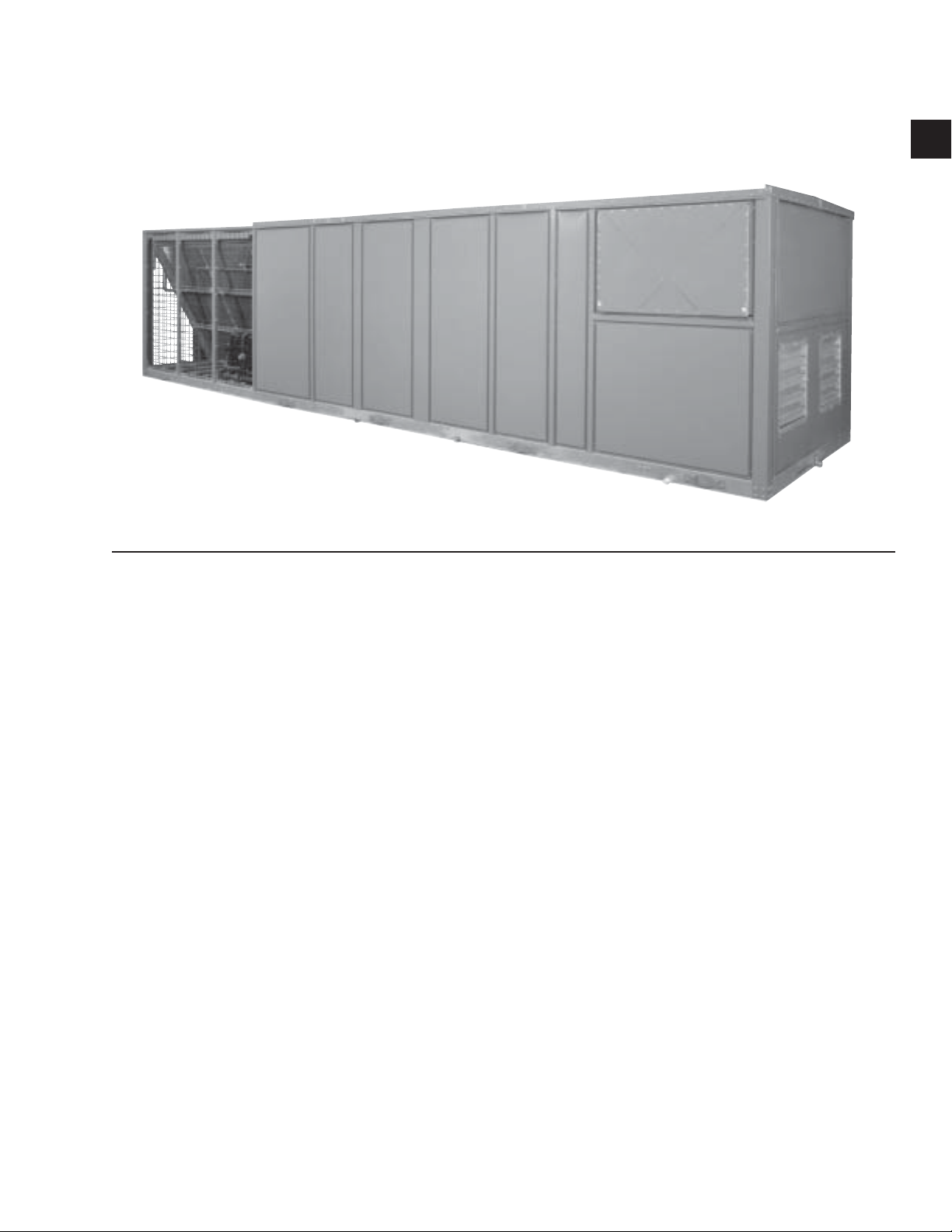
FIG. 1-1 – PACKAGED ROOFTOP AIR CON DI TION ING UNIT
ECOLOGICAL AND ECONOMICAL DESIGN
• High Effi ciency eco
2
rooftop units are optimized
Condensing Section
for HFC-410A refrigerant. YORK provides the
FIRST standard product offering that meets the
latest ASHRAE 90.1 energy effi ciency requirements.
• Cooling and Heating – Superior op er at ing per-
for mance provides lower operating costs. Smaller
steps of cool ing capacity pro vide tighter con trol
of build ing environment and oc cu pant comfort
while optimizing energy effi ciency.
• Indoor Air Quality (IAQ) – Outside air econ-
o miz ers pro vide en er gy sav ings in free cooling
mode, and can pro vide a health i er and more
comfortable build ing en vi ron ment by in tro duc ing
fresh outside air into the build ing as needed. Indoor Air Quality (IAQ) re quire ments for building
ventilation and com fort are con trolled through
the microprocessor con trol pan el.
• Premium-Effi ciency Motors – Premium-effi -
ciency motors are available for optimum energy
effi ciency. All mo tors used on the eco2 pack aged
roof top air con di tion er meet U.S. EPACT 1992
min i mum re quire ments.
High-effi ciency motors are standard. Motors are
available in ODP or TEFC construction.
LD13271
• Scroll Compressors – Reliable, efficient,
trouble-free operation is the true measure of a
packaged rooftop’s value. That’s why YORK
2
eco
Packaged Rooftop Air Conditioners use
established scroll-compressor technology to
deliver dependable, eco nom i cal performance
in a wide range of ap pli ca tions. With the eco
Packaged Rooftop, you get the latest generation
of compressor en hance ments added to the scroll’s
inherent strengths. The sim plic i ty of a hermetic
scroll compressor allows the use of fewer moving
parts to minimize breakdown.
• Multiple Compressor Staging – Through the
2
use of the scroll compressor, the eco
ity to stage it’s cooling by enabling and disabling
mul ti ple single stage compressors on multiple
circuits. These compressors are manifolded together in two independent circuits.
• Compressor Circuiting – The eco
so that only 2 scroll compressors are in tandem
within one refrigeration circuit. This means more
reliable com pres sors, and less equipment down
time. With multiple circuits, if a compressor
should ever fail on one circuit, the other circuit/s
will re main op er a tion al to work to maintain occupied loads. The eco2 sys tem has 2 circuits in
the unit.
has the abil-
2
is designed
2
JOHNSON CONTROLS
13
Page 14

Introduction
FORM 100.50-NOM6 (1207)
Compressor Sound Blankets – Optional factory
•
in stalled sound blankets can be installed to further
reduce com pres sor sound attenuation.
• Replaceable core fi lter driers – The optional
2
re place able core fi lter driers on the eco
provides
a con ve nient means for maintaining and optimizing the units refrigeration system. Eliminating
ad di tion al fi eld pen e tra tions into the refrigerant
circuit, which could lead to potential problems,
reduce the worry of re frig er ant circuit contamination.
• Low Ambient Operation – Head-pressure con-
trol is accomplished via a VFD motor controller
rather than an ineffi cient and noisy condenser fan
damper. By varying the speed of the condenser
fan, better control and quieter operation is obtained during the colder months. Low ambient
controls are available on all systems offering
higher rooftop cooling capacity than competitive
units.
• Condenser Fan Motors – The condenser fan
2
mo tors used on the eco
unit are Totally Enclosed
Air Over (TEAO) to provide maximum durability
through any season.
• Condenser Coils – Are available in various
ma te ri als and coatings to suit almost any type of
ap pli ca tion. Alu mi num or copper fi ns, pre-coat ed
or post-coated fi ns are available. The coating is
applied us ing an epoxy coating on the aluminum
coil. Each coil option is benefi cial when the unit
must operate under ex treme con di tions. The use
of an epoxy coated coil is recommended for units
installed in a corrosive environment.
Heating Section
• Staged gas heat – The eco
2
rooftop gas furnace
is an induced-draft gas furnace designed for
high ef fi cien cy and reliability. The furnace uses
an alu mi nized steel tubular heat exchanger and
op er ates at tem per a tures suffi cient to prevent
acidic ex haust gases from con dens ing in the
heat ex chang er at low fi re rates, unlike drum and
tube style fur nac es that generate condensation
for ma tion. Up to three stages of heat are available.
An optional stainless steel heat exchanger is also
available.
• Electric – The eco
2
is also available with an
elec tri cal heater that can range from 40kW up to
50kW. De pend ing on the size of the heat re quired,
2
the eco
can have 3 steps of control helping to
provide tighter control of the supply and zone
con di tioned air. With the uti li za tion of this multi
step func tion, the eco2 can ef fec tive ly reduce en er gy con sump tion by bring ing on smaller stages
of heat while main tain ing the max i mum level of
com fort.
• Steam and Hot water – This option will be
available in the future.
• Hot Gas By-pass – Is standard on VAV units.
• Condenser Coil Protection – The eco
able with a wire mesh guard for optimum coil
protection.
14
2
is avail-
JOHNSON CONTROLS
Page 15

AIR MANAGEMENT
FORM 100.50-NOM6 (1207)
1
• DWDI Airfoil fans – High effi ciency fans are
used to im prove ap pli ca tion fl exibility, and address sound and ap pli ca tion con cerns.
• Building pressure control – Ex haust fans and
barometric relief dampers are available to meet
building pressure control requirements. Select
the most appropriate option for a given ap pli ca tion.
• Low sound options – Allow for application of
the eco2 unit in sound-sensitive applications
such as the aters and downtown areas. Contact
JOHNSON CONTROLS for more details on
site-specifi c requirements.
• Variable Frequency Drives – When a VAV unit
is or dered, the eco2 comes standard with vari able
fre quen cy drives (VFD’s). The VFD can optimize
a sys tems performance by modulating the sup ply
fan motor speed to reduce energy con sump tion
by as much as 40% while maximizing oc cu pant
comfort.
• Fan Spring Isolation – Two-inch spring iso la tion
is used to prevent vibration transmission from the
roof top unit’s supply fan to the building.
The control can also be connected to a computer
for greater access to programming and operating
information.
• Communication -The controller is designed
to communicate using Modbus RTU protocol.
Through the addition of a ModLINC translator,
the unit can also communicate using BACnet
MS/TP protocol.
INDOOR AIR QUALITY
• Double Sloped Stainless Steel Drain Pan – The
eco2’s standard Stainless Steel drain pan meets
ASHRAE 62 requirements for condensate drain-
age to improve indoor air quality. Solid wall liners
encase insulation and prevent moisture dam age.
Additional benefi ts include easy cleanability and
isolates insulation from conditioned airstream.
• Double Wall Construction – Is the standard
con struc tion of the eco2 and incorporates powder
coat ed pre-fabricated outer panels and corner post
for max i mum exterior surface protection.
CONTROLS
• Rooftop Controller - The unit is designed to
use the Simplicity Elite control. This control
has been used with the 25 to 40 ton Millennium
product for many years. The control is designed
to operate with conventional room control input.
This allows the same control to be used on installations requiring 25 to 60 tons of cooling.
The board is equipped with four program but-
tons and two character displays for use by the
technician. They allow for access to the most
important board functions, current operating
data, and current alarms as well as the last fi ve
alarms in the history memory buffer. The buttons
and displays are also used to program the control
with the correct confi guration and set points.
JOHNSON CONTROLS
15
Page 16

Introduction
FORM 100.50-NOM6 (1207)
Factory Shrinkwrap – All eco2 rooftop units
•
can be ordered from the factory with an optional
factory-fresh shrinkwrap pack ag ing. This eliminates the contractors worries about dirt and debris
clogging up condenser coils or moisture leaking
into the air han dler on the units way to the job
site or rigging yard.
• Demand Ventilation Option – Can be incorpo-
rated into the unit to improve indoor air quality
and help manage indoor pollutants such as CO
or other harmful air borne con tam i nates out of
the occupied spaces for maximum comfort and
safety. Activation of this se quence can easily be
ac com plished using a CO2 sensor installed in the
conditioned space. CO2 sensors are typically
used with de mand ventilation; however other
sensors may be applied to control indoor con tam i nants such as volatile or gan ic com pounds
(VOCs).
• Smoke Purge – Is also available to evacuate
smoke due to fi re from a room or zone.
• Filtration – The eco
types of fi ltration to meet the different needs and
re quire ments of today's rooftop applications,
including 2-inch throwaway, pleated, carbon,
and cleanable fi l ters and 12-inch high effi ciency
rigid fi lters.
ELECTRICAL
• Single Point Power – The eco
dard with single point power connections to make
in stal la tion quick and easy.
2
is confi gured for various
2
unit comes stan-
SERVICE AND INSTALLATION
• Access Doors – Full-sized access doors provide
easy access into the unit for routine maintenance
and inspection.
The unit can be purchased with a “Both Side
Access” option for additional accessibility.
• Service Valves – Oversized ser vice valves to
pro vide iso la tion and quick rec la ma tion and
2
charg ing of sys tem re frig er ant are avail able as
an option to min i mize down time and sim pli fy
the service and repair task.
• Convenience Outlet – For maintenance tasks
re quir ing power tools, an optional 110V GFCI
pow er supply can power lights, drills or any other
power hand tool needed.
• Factory Run-Tested – Each unit is subjected
to a series of quality assurance checks as well
as an au to mat ed quality control process before
being run-tested. Fans and drives are balanced
at the fac to ry during testing. The factory run-test
ensures safe proper operation when the unit is
installed, and reduces installation and commissioning time.
• Gas Heat Sections – Are factory and leaked
checked.
• Replaceable Core Filter Drier Option – Pro-
vides a means to remove moisture, dirt and debris
from the re frig er a tion circuit in the event it is
opened.
• Dual Point Power – Can be factory installed for
ap pli ca tions that require the mechanical heating
and cooling functions to be separated from the
air han dling functions. This enables the unit to
be op er at ed in an emergency condition while
minimizing power consumption.
• Unit-Mounted Disconnect – Is available as an
op tion to minimize time at installation of equipment and to reduce necessary field installed
items.
16
JOHNSON CONTROLS
Page 17
SECTION 2 – INSTALLATION
FORM 100.50-NOM6 (1207)
APPROVALS
Designed certifi ed by CSA, ETL, CETL as follows:
1. For use as a forced air furnace with cooling unit
(gas heat models).
2. For outdoor installation only.
3. For installation on combustible ma te ri al and may
be installed directly on combustible fl oor ing or
Class A, Class B or Class C roof covering ma te ri als.
4. For use with natural gas or LP.
5. When used with LP propane gas one of the following conversion kits must be installed before the gas
heat section is fi red:
375,000 BTU Input - 385-01866-001
750,000 BTU Input - 385-01866-002
1,125,000 BTU Input - 385-01866-003
Not suitable for use with conventional venting
systems.
LIMITATIONS
The installation of this unit must conform to local
build ing codes, or in the absence of local codes, with
ANSI 223.1 Natural Fuel Gas Code and /or CAN/CGA
B149 in stal la tion codes.
In U.S.A.:
1. National Electrical Code ANSI/NFPA No. 70 - Latest Edition.
2. National Fuel Gas Code Z223.1 - Latest Edition.
3. Gas-Fired Central Furnace Standard ANSI Z21.47
- Latest Edition.
4. Local gas utility requirements.
TABLE 2-1 – VOLTAGE LIMITATIONS
UNIT POWER
SUPPLY
575-3-60 518 632
480-3-60 415 506
230-3-60 207 253
200-3-60 187 228
VOLTAGE VARIATIONS
MIN. VOLTS MAX. VOLTS
Refer to Table 2-15 for airfl ow and entering air/ambient
conditions limitations, and Table 2-1 for voltage
limitations.
If the VAV boxes in the conditioned
space have hydronic heating coils
installed, it is the responsibility of the
installing contractor to take appropriate measures to protect the hydronic
coils against low unit supply air temperatures that could result in the freeze
up and rupture of the coils.
UNIT INSPECTION
Immediately upon receiving the unit, it should be
in spect ed for possible damage, which may have
oc curred during transit. If damage is evident, it should
be noted in the car ri er’s freight bill. A writ ten re quest
for in spec tion by the carrier’s agent should be made at
once. See “In struc tion” man u al, Form 50.15-NM for
more in for ma tion and de tails.
To ensure warranty cov er age, this
equip ment must be commissioned and
serviced by an authorized JOHNSON
CONTROLS ser vice mechanic or a
qual i fi ed service person ex pe ri enced
in pack aged roof top in stal la tion.
In stal la tion must comply with all ap pli ca ble codes, par tic u lar ly in regard
to elec tri cal wir ing and other safety
el e ments such as relief valves, HP
cut-out settings, de sign work ing pres sures, and ven ti la tion re quire ments
con sis tent with the amount and type
of re frig er ant charge.
Lethal voltages exist within the con trol
panels. Before servicing, open and tag
all dis con nect switches.
LOCATIONS AND CLEARANCES
GENERAL
The eco2 air conditioning units are designed for outdoor
installation. When selecting a site for installation, be
guided by the following conditions:
• Unit must be installed on a level surface.
• For the outdoor location of the unit, select a place
having a minimum sun exposure and an adequate
supply of fresh air for the condenser.
2
JOHNSON CONTROLS
17
Page 18
Installation
FORM 100.50-NOM6 (1207)
• Also avoid locations beneath windows or between structures.
• Optional condenser coil protection should be used
for seashore locations or other harsh environments.
• The unit should be installed on a roof that is structurally strong enough to support the weight of the unit
with a minimum of defl ection. It is recommended
that the unit(s) be installed not more than 15 feet
from a main support beam to provide proper
structural support and to minimize the transmission of sound and vibration. Ideally, the center of
gravity should be located over a structural support
or building column.
• Location of unit(s) should also be away from
building fl ue stacks or exhaust ventilators to
prevent possible reintroduction of contaminated
air through the outside air intakes.
• Be sure the supporting structures will not obstruct
the duct, gas or wiring connections.
away from sound sensitive areas such as conference
rooms, auditoriums and executive offi ces and any other
room that may have potential for tenant occupancy.
Possible locations could be above hallways, mechanical
or utility rooms.
Finally, service clearances should be maintained in
rooftop design to insure safe access to the unit. Unit
clearances are designed so that technicians have enough
space between units, building walls, and edges of
building to gain access safely. In cases where space is
limited, please call your local York representative for
additional information.
The clearances shown are to provide
adequate condenser airfl ow and service access to inside the unit. Additional clearance should be considered
for component replacement such as
compressors, evaporator coils, and
supply or exhaust fans.
LOCATION
Of the many factors that can effect the location of
equipment, some of the most important to consider are
Structural, Acoustical and Service clearances. Proper
attention should be made at the design stage to ensure
proper structural support. In cases where equipment is
being replaced, be aware of building design to insure
support is adequate for the application.
The next most important consideration in applying roof
top equipment is that of sound from the equipment.
Special care should be made to keep the roof top unit
While it is a common practice to operate the fan as soon as possible (air
movement during construction) on the
job site, the incomplete ductwork and
missing diffuser grilles will greatly
reduce air resistance and will allow
the fan to operate beyond design parameters. This practice may result in
water carry over and fl ooding of the
unit. Also, the supply fan motor may
overamp and become damaged.
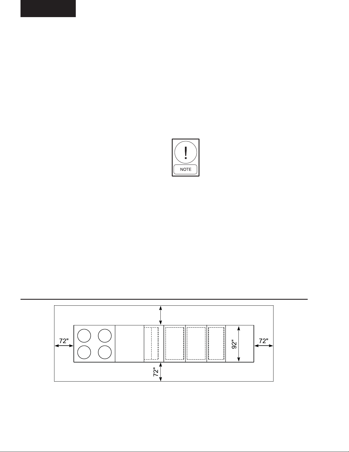
96"
NOTES:
1. 10' clearance minimal over the top of the condensing unit.
2. Only one adjacent wall can exceed unit height.
3. 12' clearance required to adjacent units.
FIG. 2-1 – UNIT CLEARANCES
18
LD13267
4. 8' service access recommended on one side.
5. Economizer and exhaust hoods, where applicable, are folded
inside unit for shipment.
6. Dim. is to outside of lifting lugs.
JOHNSON CONTROLS
Page 19
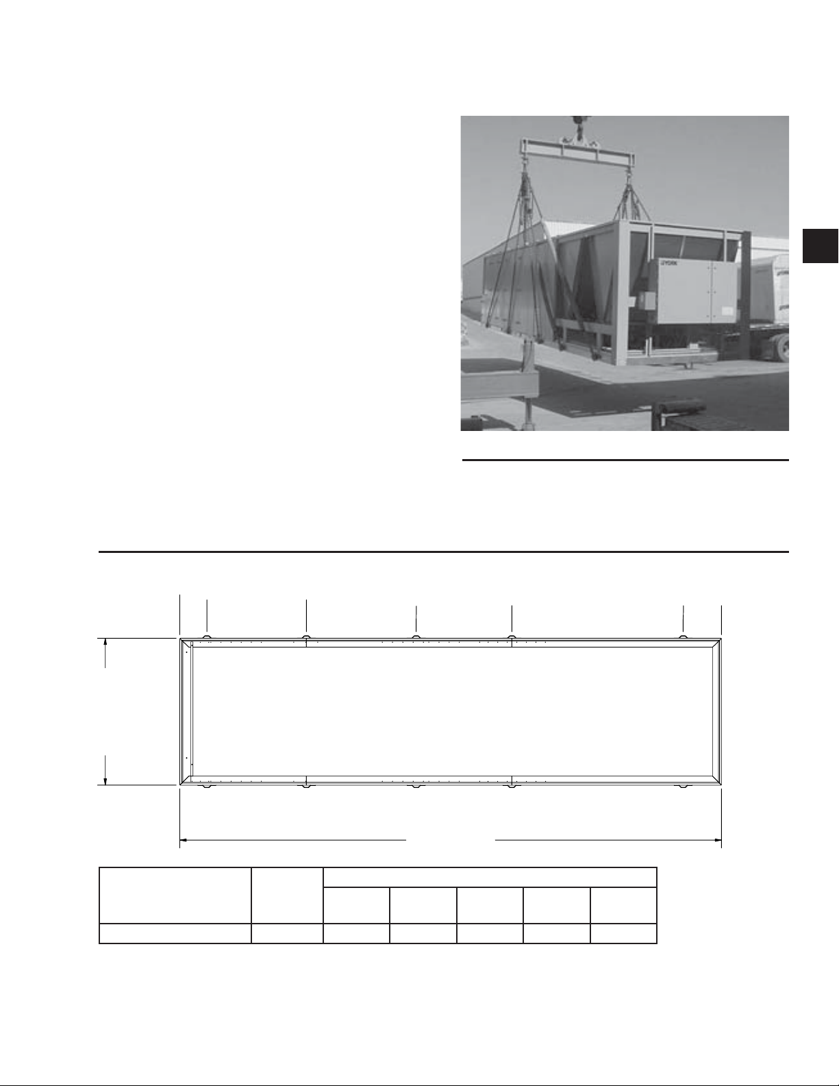
RIGGING AND HANDLING
Proper rig ging and handling of the equip ment is
man da to ry during un load ing and setting it into position
to re tain warranty status. All lifting lugs must be used
to pre vent twisting and damage to the unit.
Care must be taken to keep the unit in the upright
po si tion during rigging and to prevent damage to the
water-tight seams in the unit casing. Avoid unnecessary
jar ring or rough handling.
Typical rigging using proper spreader bars and cables
is shown in Figure 2-3. See Figure 2-2 for number
and location of the lifting lugs by unit size. It is also
mandatory that an ex pe ri enced and reliable rigger be
selected to han dle un load ing and fi nal place ment of
the equipment. The rig ger must be advised that the unit
contains internal com po nents and that it be han dled in
an upright po si tion. Care must be exercised to avoid
twisting the equip ment struc ture.
Unit weights are listed under Table 2-2 in this manual.
These weights must be re ferred to when selecting a crane
for rig ging and fi guring roof weight loads. Con tact your
FORM 100.50-NOM6 (1207)
2
00543vip
FIG. 2-3 – UNIT RIGGING
JOHNSON CONTROLS Sales Offi ce if you have any
ques tions re gard ing unit weights.
%
+
7
'
,
:
(
'
,
6
7
8
2
$
UNIT SIZE TONS
LENGTH
INCHES
UNIT
2876,'(/(1*7+
DIMENSION
1-2 3-4 5-6 7-8 9-10
50 - 61 STD CABINET 339 16.91 79.21 147.93 207.81 315.04
FIG. 2-2 – LIFTING LUG LOCATIONS
LD13272
&
&21'(16(5(1'
'
JOHNSON CONTROLS
19
Page 20
Installation
FORM 100.50-NOM6 (1207)
UNIT WEIGHTS
TABLE 2-2 – UNIT WEIGHTS - 050-061 MODELS
MODEL SIZE 050 051 060 061
BASIC UNIT* 7433 7433 7800 7819
ECONOMIZERS
NO OUTSIDE AIR 240 240 240 240
25% OUTSIDE AIR FIXED POSITION MAUAL
DAMPER
25% OUTSIDE AIR 2 POSITION ACTUATED
DAMPER
FULL MODULATION WITH MINIMUM POSITION 476 476 476 476
POWER EXHAUSTS
FAN, MOTOR, MODULATING DAMPER AND HOOD 501 501 501 501
FAN, MOTOR, VFD, BAROMETRIC DAMPER AND
HOOD
GAS HEAT
375 MBH 162 162 162 162
750 MBH 324 324 324 324
1125 MBH 486 486 486 486
OPTIONS
OPEN PERIMETER CURB 544 544 544 544
CONDENSER COIL WIRE GUARD 64 64 64 64
COPPER CONDENSER COILS (ADDITIONAL) 516 516 773 773
12” RIGID FILTERS (ADDITIONAL) 319 319 319 319
*UNIT INCLUDES FC FAN W/ 20 HP MOTOR, VFD AND 2” THROWAWAY FILTERS
446 446 446 446
476 476 476 476
506 506 506 506
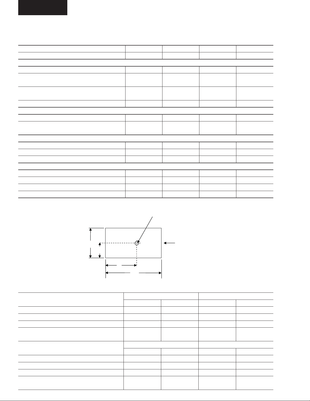
Center of Gravity
B C
Condenser
92
Y
A
D
Coil End
339
LD08298
TABLE 2-3 – UNIT CENTER OF GRAVITY
MODEL
BASIC UNIT 184.1 50.2 184.1 50.2
BASIC UNIT W/ ECON. 191.0 49.9 191.0 49.9
BASIC UNIT W/ ECON. & HEATING 187.4 50.0 187.4 50.0
BASIC UNIT W/ ECON. & HEATING & POWER
EXHAUST
MODEL
BASIC UNIT 179.8 49.9 179.6 50.0
BASIC UNIT W/ ECON. 186.7 49.7 186.5 49.7
BASIC UNIT W/ ECON. & HEATING 183.5 49.8 183.2 49.8
BASIC UNIT W/ ECON. & HEATING & POWER
EXHAUST
XYXY
194.9 49.5 194.9 49.5
XYXY
190.9 49.3 190.7 49.3
20
050 051
060 061
JOHNSON CONTROLS
Page 21
FORM 100.50-NOM6 (1207)
UNIT WEIGHTS (CONTINUED)
TABLE 2-4 – UNIT CORNER WEIGHTS - 050-061 MODELS
MODEL
BASIC UNIT 1835 2201 1852 1545 1835 2201 1852 1545
BASIC UNIT W/ ECON. 2039 2417 1873 1580 2039 2417 1873 1580
BASIC UNIT W/ ECON. & HEATING 2118 2521 2041 1715 2118 2521 2041 1715
BASIC UNIT W/ ECON. & HEATING & POWER
EXHAUST
ABCDABCD
2366 2751 2034 1750 2366 2751 2034 1750
050 051
2
MODEL
BASIC UNIT 1894 2244 1986 1676 1893 2250 1997 1680
BASIC UNIT W/ ECON. 2097 2461 2008 1711 2096 2466 2018 1715
BASIC UNIT W/ ECON. & HEATING 2177 2565 2175 1846 2176 2570 2185 1850
BASIC UNIT W/ ECON. & HEATING & POWER
EXHAUST
ABCDABCD
2424 2795 2168 1881 2423 2801 2178 1885
060 061
Unit Placement
• Elevated – Elevated roof curbs or dunnage steel
can be used to support the unit in order to raise it
to specifi c heights. When this type of placement
is required, be sure to keep unit access in mind.
Cat walks or other forms of unit access may be
required to one or both sides of the unit, depending on your area of the country and the local codes
that are enforced. Please check with local offi cials
to ensure the application conforms to local codes
and regulations.
• Ground Level Locations – It is important that
the units be installed on a substantial base that
will not settle, causing strain on the refrigerant
lines and sheet metal and resulting in possible
leaks. A one piece concrete slab with footers
extended below the frost line is highly recommended. Additionally, the slab should be isolated
from the main building foundation to prevent
noise and vibration transmission to the building
structure.
For ground level installations, precautions should
be taken to protect the unit from tampering by, or
injury to, unauthorized persons. Erecting a fence
around the unit is common practice.
JOHNSON CONTROLS
21
Page 22

Installation
ROOF CURB INSTALLATION
YORK offers an optional roof curb designed specifi cally
for the eco2 foot print. This curb comes as an open
condenser model and is shipped disassembled and
requires fi eld assembly during installation. Refer to
the Installation Manual that is shipped with the roof
curb for specifi c instructions. For bottom supply and
return openings, the curb has matching connections to
ease installation.
The curb should be located according to the location
recommendations above, and properly sealed to prevent
moisture and air leakage into and out of the duct system.
Flexible collars should be used when connecting the
duct work to prevent unit noise transmission and
vibration into the building. The roof curb drawings
contained in the Johnson Controls literature are not
intended as construction documents for fi eld fabrication
of a roof curb. Johnson Controls will not be responsible
for the unit fi t up, leak integrity, or sound level with
fi eld fabricated roof curbs.
FORM 100.50-NOM6 (1207)
Construction documents for fi eld fabricated roof curbs
are available upon request.
Wood or fiber cant strips, roofing
felts, roofi ng material, caulking and
curb-to-roof fasteners are to be fi eld
supplied.
22
JOHNSON CONTROLS
Page 23
FORM 100.50-NOM6 (1207)
PHYSICAL DATA
TABLE 2-5 – PHYSICAL DATA – 050-061 MODELS
UNIT SIZE 050 051 060 061
GENERAL DATA
LENGTH WITHOUT HOOD (INCHES) 339 339 339 339
WIDTH (INCHES) 92 92 92 92
HEIGHT (INCHES) 82 82 82 82
UNIT EER/ IPLV 10.3 / 10.9 10.2 / 10.6 10.1 / 10.4 10.1 / 10.3
UNIT EER/ IPV GAS HEAT
COMPRESSOR DATA (SEE TABLE 2-6)
QUANTITY 4 4 4 4
TYPE SCROLL SCROLL SCROLL SCROLL
UNIT CAPACITY STEPS 4 4 4 4
REFRIGERANT (410A)
SYSTEM 1 50 lbs - 0 oz 50 lbs - 0 oz 58 lbs - 11 oz 58 lbs - 11 oz
SYSTEM 2 50 lbs - 0 oz 50 lbs - 0 oz 58 lbs - 11 oz 58 lbs - 11 ozs
SUPPLY FAN
QUANTITY 1 1 1 1
TYPE FC FC FC FC
SIZE 28 - 28 28 - 28 28 - 28 28 - 28
MOTOR SIZE RANGE (HP) 10 - 40 10 - 40 10 - 40 10 - 40
AIR FLOW RANGE (CFM) COOLING MIN. 10,000 - 22,500 10,000 - 22,500 12,500 - 24,000 10,000 - 24,000
STATIC PRESSURE RANGE (TOTAL) 1.0” - 6.0” 1.0” - 6.0” 1.0” - 6.0” 1.0” - 6.0”
OPTIONAL SUPPLY FAN
QUANTITY 1 1 1 1
TYPE AF AF AF AF
SIZE 28 28 28 28
MOTOR SIZE RANGE (HP) 10 - 40 10 - 40 10 - 40 10 - 40
AIR FLOW RANGE (CFM) COOLING MIN. 10,000 - 22,500 10,000 - 22,500 10,000 - 24,000 10,000 - 24,000
STATIC PRESSURE RANGE (TOTAL) 1.0” - 8.0” 1.0” - 8.0” 1.0” - 8.0” 1.0” - 8.0”
EXHAUST FAN
QUANTITY FANS/MOTORS 2 / 1 2 / 1 2 / 1 2 / 1
TYPE FC FC FC FC
SIZE 18 - 18 18 - 18 18 - 18 18 - 18
MOTOR SIZE RANGE (HP) 5 - 20 5 - 20 5 - 20 5 - 20
AIR FLOW RANGE (CFM) 4,000 - 22,500 4,000 - 22,500 4,000 - 24,000 4,000 - 24,000
STATIC PRESSURE RANGE (TOTAL) 0.1” - 1.5” 0.1” - 1.5” 0.1” - 1.5” 0.1” - 1.5”
EVAPORATOR COIL
SIZE (SQUARE FEET) 52 52 52 52
ROWS/FPI 3 / 17 3 / 17 4 / 17 4 / 17
CONDENSER COIL
SIZE (SQUARE FEET) 88 88 88 88
ROWS/FPI 2 / 17 2 / 17 3 / 17 3 / 17
CONDENSER FANS
QUANTITY 4 4 4 4
TYPE PROP. PROP. PROP. PROP.
DIAMETER (INCHES) 36 36 36 36
MOTOR HP 2 2 2 2
FILTERS - 2” THROWAWAY (PRE-FILTER POSITION)
QUANTITY 8 / 12 8 / 12 8 / 12 8 / 12
SIZE (LENGTH X WIDTH) (IN.) 25X16 / 25X20 25X16 / 25X20 25X16 / 25X20 25X16 / 25X20
TOTAL FILTER FACE AREA (SQUARE FEET) 61.6 61.6 61.6 61.6
FILTERS - 2” CLEANABLE (PRE-FILTER POSITION)
QUANTITY 8 / 12 8 / 12 8 / 12 8 / 12
SIZE (LENGTH X WIDTH) (IN.) 25X16 / 25X20 25X16 / 25X20 25X16 / 25X20 25X16 / 25X20
TOTAL FILTER FACE AREA (SQUARE FEET) 63.9 63.9 63.9 63.9
2
JOHNSON CONTROLS
23
Page 24
Installation
FORM 100.50-NOM6 (1207)
PHYSICAL DATA (CONTINUED)
TABLE 2-5 – PHYSICAL DATA - 050-061 MODELS (CONTINUED)
UNIT SIZE 050 051 060 061
FILTERS - 2” PLEATED, 30% EFFICIENT (PRE-FILTER POSITION)
QUANTITY 8 / 12 8 / 12 8 / 12 8 / 12
SIZE (LENGTH X WIDTH) (IN.) 25X16 / 25X20 25X16 / 25X20 25X16 / 25X20 25X16 / 25X20
TOTAL FILTER FACE AREA (SQUARE FEET) 63.9 63.9 63.9 63.9
FILTERS -12” RIGID 65%, 2” 30% PREFILTER (PRE-FILTER POSITION)
QUANTITY 1 / 4 / 9 1 / 4 / 9 1 / 4 / 9 1 / 4 / 9
SIZE (LENGTH X WIDTH) (IN.)
TOTAL FILTER FACE AREA (SQUARE FEET) 43.0 43.0 43.0 43.0
FILTERS -12” RIGID 95%, 2” 30% PREFILTER (PRE-FILTER POSITION)
QUANTITY 1 / 4 / 9 1 / 4 / 9 1 / 4 / 9 1 / 4 / 9
SIZE (LENGTH X WIDTH) (IN.)
TOTAL FILTER FACE AREA (SQUARE FEET) 44.6 44.6 44.6 44.6
FILTERS - 2” CARBON (PRE-FILTER POSITION)
QUANTITY 8 / 12 8 / 12 8 / 12 8 / 12
SIZE (LENGTH X WIDTH) (IN.) 25X16 / 25X20 25X16 / 25X20 25X16 / 25X20 25X16 / 25X20
TOTAL FILTER FACE AREA (SQUARE FEET) 63.9 63.9 63.9 63.9
FILTERS - 12” RIGID 95% IN POST-FILTER POSITION
QUANTITY 1 / 3 / 9 1 / 3 / 9 1 / 3 / 9 1 / 3 / 9
SIZE (LENGTH X WIDTH) (IN.)
TOTAL FILTER FACE AREA (SQUARE FEET) 41.8 41.8 41.8 41.8
GAS FURNACES
STAGED FURNACE SIZES (INPUT/OUTPUT/STEPS)
GAS PRESSURE RANGE 4.5-13.5" WC 4.5-13.5" WC 4.5-13.5" WC 4.5-13.5" WC
AIRFLOW RANGE
(MIN HEATING)
MINIMUM OA TEMP FOR MECH. CIG. 40.0 °F 40.0 °F 40.0 °F 40.0 °F
LOW AMBIENT OPTION MIN. OA TEMP 0.0 °F 0.0 °F 0.0 °F 0.0 °F
375 MBH 7,500 7,500 11,500 11,500
750 MBH 14,000 14,000 14,000 14,000
1125 MBH 21,000 21,000 21,000 21,000
16X20/25X16/
25X20
16X20/25X16/
25X20
16X20/25X16/
25X20
16X20/25X16/
25X20
16X20/25X16/
25X20
16X20/25X16/
25X20
375 MBH / 300 MBH / 1 STEP
750 MBH / 600 MBH / 2 STEPS
1125 MBH / 900 MBH / 3 STEPS
16X20/25X16/
25X20
16X20/25X16/
25X20
16X20/25X16/
25X20
16X20/25X16/
25X20
16X20/25X16/
25X20
16X20/25X16/
25X20
TABLE 2-6 – PHYSICAL DATA - COMPRESSORS
COMPRESSORS UTILIZED COMPRESSOR NOMINAL TONS
SYSTEM 1 SYSTEM 2 SYSTEM 1 SYSTEM 2
MODEL
“COMPR
050 ZP137 ZP120 ZP137 ZP120 13.58 12.53 13.58 12.53 26.0 52.0 76.0 100.0
051 ZP137 ZP137 ZP137 ZP137 13.58 13.58 13.58 13.58 25.0 50.0 75.0 100.0
060 ZP182 ZP137 ZP182 ZP137 17.95 13.30 17.95 13.30 28.7 57.4 78.7 100.0
061 ZP182 ZP137 ZP182 ZP154 17.95 13.30 17.60 14.86 28.2 55.8 76.7 100.0
# 1”
“COMPR
# 2”
“COMPR
# 3”
“COMPR
# 4”
24
“COMPR
# 1”
“COMPR
# 2”
“COMPR
# 3”
“COMPR
# 4”
CAPACITY %
“STAGE1”“STAGE2”“STAGE3”“STAGE
4”
JOHNSON CONTROLS
Page 25
GENERAL ARRANGEMENT DRAWING – 050-061 MODELS
BOTTOM SUPPLY / BOTTOM RETURN
SECTION DESCRIPTIONS:
EE = Economizer
FE = Fan Exhaust
_F = Filter Segments
CC = Cooling Coils
FS = Supply Fan
DP = Discharge Plenum
CO = Condenser Section
60.00
CLEAR
FOR AIR
FORM 100.50-NOM6 (1207)
BOTH
SIDES
INTAKE
136.82
FRONT VIEW
2
339.00
170.31
ELECTRICAL SERVICE
86.50
69.83
75.58
5.50
5.74
4.56
OA OA
67.25
191.19
230.62
84.00
CLEAR
EE
_F
FS CC
FE
1-1/4" FPT
DRAINS
BOTH SIDES
1.50
46.00
60.00
39.00
AIRFLOW
TOP VIEW
120.00 CLEAR
91.00
PULL
CLEAR
FOR COIL
DP
CO
SIDE VIEW
(LEFT SIDE)
FIG. 2-4 – GENERAL ARRANGEMENT DRAWING
JOHNSON CONTROLS
82.00
92.00
100.50
REAR VIEW
SWING
30.00 DOOR
BOTH SIDES
CLEARANCE
78.00 CLEAR
FOR COIL PULL
LD08295
25
Page 26
Installation
GENERAL ARRANGEMENT DRAWINGS (CONTINUED)
BOTTOM SUPPLY / SIDE RETURN
SECTION DESCRIPTIONS:
EE = Economizer
FE = Fan Exhaust
_F = Filter Segments
CC = Cooling Coils
FS = Supply Fan
DP = Discharge Plenum
CO = Condenser Section
84.00
CLEAR
FORM 100.50-NOM6 (1207)
BOTH SIDES
60.00 CLEAR
FOR AIR INTAKE
136.82
REAR VIEW
6.28
38.37
170.31
195.38
221.00
339.00
GAS LINE CONNECTION
2-1/2" GAS OUTLET
1-1/2" MPT CONN.
GAS HEAT FLUE
ELECTRICAL SERVICE
69.83
75.58
5.74
OA OA
191.19
230.62
TOP VIEW
49.94 4.79
1-1/4" FPT DRAIN
1.50
106.00
LEFT SIDE ONLY
AIRFLOW
GAS
BURNERS
120.00 CLEAR
91.00
CLEAR
PULL
FOR COIL
SIDE VIEW
(LEFT SIDE)
NOTES:
1. 10’ clearance minimal over the top of the condensing unit.
2. Only one adjacent wall can exceed unit height.
3. 12’ clearance required to adjacent units.
4. 8’ service access recommended on one side.
5. Economizer and exhaust hoods, where applicable are folded inside unit for shipment.
FIG. 2-4 – GENERAL ARRANGEMENT DRAWING (CONT.)
26
GAS HEAT EXHAUST FLUE
FIELD INSTALLED
82.00
95.25
92.00
102.62
FRONT VIEW
30.00
BOTH
ANCE
DOOR
SIDES
SWING
CLEAR-
78.00 CLEAR
FOR COIL PULL
LD08370
JOHNSON CONTROLS
Page 27
GENERAL ARRANGEMENT DRAWINGS (CONTINUED)
BOTTOM SUPPLY / REAR RETURN
SECTION DESCRIPTIONS:
EE = Economizer
FE = Fan Exhaust
_F = Filter Segments
CC = Cooling Coils
FS = Supply Fan
DP = Discharge Plenum
CO = Condenser Section
84.00
CLEAR
FORM 100.50-NOM6 (1207)
BOTH SIDES
60.00 CLEAR
FOR AIR INTAKE
6.36
36.28
76.48
136.82
REAR VIEW
7.76
2
339.00
170.31
11.00
106.00
1-1/4" FPT
DRAINS
BOTH SIDES
1.50
46.0060.00
39.00
195.00
227.25
SIDE VIEW
(LEFT SIDE)
AIRFLOW
OA
ELECTRICAL SERVICE
OA
EE
FS CC
FE
_F
TOP VIEW
DP
120.00 CLEAR
91.00
PULL
CLEAR
FOR COIL
CO
66.00
NOTES:
1. 10’ clearance minimal over the top of the condensing unit.
2. Only one adjacent wall can exceed unit height.
3. 12’ clearance required to adjacent units.
4. 8’ service access recommended on one side.
5. Economizer and exhaust hoods, where applicable are folded inside unit for shipment.
FIG. 2-4 – GENERAL ARRANGEMENT DRAWING (CONT.)
JOHNSON CONTROLS
82.00
92.00
100.50
SWING
30.00 DOOR
FRONT VIEW
BOTH SIDES
CLEARANCE
78.00 CLEAR
FOR COIL PULL
LD08296
27
Page 28
Installation
CURB LAYOUT DRAWING / 050-061 MODELS
FORM 100.50-NOM6 (1207)
333.69
71.83
41.19
66.08
SUPPLY
229.56
35.10
21.00
66.19
RETURN
LD08297
84.50
14.00
1.75
TYP
NOTES:
1. Unit must be installed square and level.
2. Curb confi guration for “bottom” return and “bottom” supply.
3, These drawings are not intended as construction documents for the fi eld fabricated roof curbs. Johnson Controls will not be responsible for
the unit fi t up, leak integrity, or sound level for installation using fi eld fabricated roof curbs.
4. The YPAL unit does not have a base pan under the condensing section of the unit. Field fabricated roof curbs must have a cap on the top of
the condensing section of the curb to prevent moisture from entering the space. The cap design must be sloped away from the supply duct
opening to the end of the unit for the drainage of the moisture off of the top of the cap.
FIG. 2-5 – GENERAL ARRANGEMENT DRAWING
28
JOHNSON CONTROLS
Page 29
ELECTRICAL SERVICE SIZING
FORM 100.50-NOM6 (1207)
ELECTRICAL DATA
In order to use the electrical service required for
the cooling only eco2 rooftop, use the appropriate
calculations listed below from U.L. 1995. Based on the
confi guration of the rooftop, the calculations will yield
different MCA (minimum circuit ampacity), and MOP
(maximum overcurrent protection).
Using the following load defi nitions and calculations,
determine the correct electrical sizing for your unit. All
concurrent load conditions must be considered in the
calculations, and you must use the highest value for any
combination of loads.
Load Defi nitions:
• LOAD1 is the current of the largest motor – compressor or fan motor.
• LOAD2 is the sum of the remaining motor currents that may run concurrently with LOAD1.
TABLE 2-7 – COMPRESSOR DATA - R410A
MODEL MODEL
1A ZP120 33.3 239 17.9 125 12.8 80
050
051
060
061
1B ZP137 48.0 245 18.6 125 14.7 100
2A ZP121 33.3 239 17.9 125 12.8 80
2B ZP137 48.0 245 18.6 125 14.7 100
1A ZP137 48.0 245 18.6 125 14.7 100
1B ZP137 48.0 245 18.6 125 14.7 100
2A ZP137 48.0 245 18.6 125 14.7 100
2B ZP137 48.0 245 18.6 125 14.7 100
1A ZP137 48.0 245 18.6 125 14.7 100
1B ZP182 55.7 340 26.9 172 23.7 132
2A ZP137 48.0 245 18.6 125 14.7 100
2B ZP182 55.7 340 26.9 172 23.7 132
1A ZP154 51.3 300 22.4 150 19.8 109
1B ZP182 55.7 340 25.0 172 23.7 132
2A ZP137 48.0 245 18.6 125 14.7 100
2B ZP182 55.7 340 25.0 172 23.7 132
208-230/3/60 460/3/60 575/3/60
RLA* LRA RLA* LRA RLA* LRA
• LOAD3 is the current of the electric heaters
– zero for cooling only units.
• LOAD4 is the sum of any remaining currents
greater than or equal to 1.0 amp.
Use the following calculations to determine MCA
and MOP for units supplied with a single-point power
connection:
MCA = (1.25 x LOAD1) + LOAD2 + LOAD3 + LOAD4
MOP = (2.25 x LOAD1) + LOAD2 + LOAD3 + LOAD4
If the MOP does not equal a standard current rating
of an overcurrent protective device, then the marked
maximum rating is to be the next lower standard rating.
However, if the device selected for MOP is less than the
MCA, then select the lowest standard maximum fuse
size greater than or equal to the MCA.
NOMINAL VOLTAGE
2
TABLE 2-8 – POWER SUPPLY VOLTAGE LIMITS
POWER SUPPLY MINIMUM VOLTAGE MAXIMUM VOLTAGE
208/230V/3PH/60HZ 187 253
460V/3PH/60HZ 414 506
575V/3PH/60HZ 518 632
JOHNSON CONTROLS
29
Page 30
Installation
FORM 100.50-NOM6 (1207)
ELECTRIC DATA (CONTINUED)
TABLE 2-9 – SUPPLY AND EXHAUST FAN MOTOR DATA - ODP
HIGH EFFICIENCY PREMIUM EFFICIENCY
MOTOR
HP
5 14.0 13.8 8.3 6.9 5.3 5 13.8 13.2 6.6 5.2
7.5 21.7 20.0 13.3 10.0 8.2 7.5 20.0 19.4 9.7 7.4
10 28.2 26.0 17.5 13.0 11.0 10 26.0 25.0 12.5 10.3
15 41.0 38.0 24.5 19.0 16.2 15 37.4 35.4 17.7 14.1
20 53.0 48.0 32.0 24.0 19.8 20 49.4 47.0 23.5 18.9
25 66.0 62.0 39.0 31.0 23.8 25 63.3 60.0 30.0 24.2
30 84.0 72.0 46.0 36.0 29.0 30 74.1 70.0 35.0 28.0
40 106.0 98.0 59.0 49.0 38.8 40 97.5 92.0 46.0 37.4
208/3/60 230/3/60 380/3/60 460/3/60 575/3/60 208/3/60 230/3/60 460/3/60 575/3/60
FLA FLA FLA FLA FLA FLA FLA FLA FLA
NOMINAL VOLTAGE
MOTOR
HP
TABLE 2-10 – SUPPLY AND EXHAUST FAN MOTOR DATA - TEFC
HIGH EFFICIENCY PREMIUM EFFICIENCY
MOTOR
HP
5 15.4 14.2 8.1 7.1 5.4 5 13.6 13.0 6.5 5.2
7.5 21.2 19.6 12.0 9.8 8.2 7.5 21.0 18.8 9.4 8.0
10 27.5 25.6 16.8 12.8 11.4 10 26.0 25.0 12.5 10.0
15 40.0 37.0 23.8 18.5 15.3 15 38.9 37.0 18.5 14.8
20 54.0 50.0 30.0 25.0 19.1 20 51.0 48.0 24.0 19.0
25 64.0 60.0 39.0 30.0 25.0 25 63.3 60.0 30.0 23.9
30 78.0 72.0 46.0 36.0 29.6 30 77.0 72.0 36.0 29.0
40 101.0 94.0 57.0 47.0 38.0 40 99.0 92.0 46.0 36.8
208/3/60 230/3/60 380/3/60 460/3/60 575/3/60 208/3/60 230/3/60 460/3/60 575/3/60
FLA FLA FLA FLA FLA FLA FLA FLA FLA
NOMINAL VOLTAGE
MOTOR
HP
NOMINAL VOLTAGE
NOMINAL VOLTAGE
TABLE 2-11 – CONDENSER FAN MOTOR RLA - STANDARD FAN
RLA EACH MOTOR
MODEL
50-61 TONS 4 29.2 24.8 12.4 10.0
QUANTITY OF
FANS
208V/3PH/60HZ 230V/3PH/60HZ 460V/3PH/60HZ 575V/3PH/60HZ
7.3 6.2 3.1 2.5
208V/3PH/60HZ 230V/3PH/60HZ 460V/3PH/60HZ 575V/3PH/60HZ
TABLE 2-12 – CONDENSER FAN MOTOR RLA - LOW SOUND FAN (FUTURE OPTION)
RLA EACH MOTOR
MODEL
50-61 TONS 4 32.4 27.6 13.6 12.0
QUANTITY OF
FANS
208V/3PH/60HZ 230V/3PH/60HZ 460V/3PH/60HZ 575V/3PH/60HZ
7.3 6.2 3.1 2.5
208V/3PH/60HZ 230V/3PH/60HZ 460V/3PH/60HZ 575V/3PH/60HZ
TABLE 2-13 – MISCELLANEOUS ELECTRICAL DATA
NOMINAL VOLTAGE
DESCRIPTION
CONTRL X’FMR. 500 VA 2.4 1.1 0.9 2
CONVENIENCE OUTLET 9.6 4.4 3.5 N/A
GAS HEAT 9.6 4.4 3.5 5.3
208 / 230V 460V 575V 380V-60
AMPS AMPS AMPS AMPS
30
JOHNSON CONTROLS
Page 31

ELECTRIC DATA (CONTINUED)
TABLE 2-14 – ELECTRIC HEAT
NOMINAL VOLTAGE
KW
40 96 96 48 40
80 193 193 96 80
108 260 260 130 109
150 — — 181 151
208/3/60
AMPS
230/3/60
AMPS
460/3/60
AMPS
575/3/60
AMPS
FORM 100.50-NOM6 (1207)
2
TABLE 2-15 – AIRFLOW AND ENTERING AIR/AMBIENT LIMITATIONS
Limitations Model Size
50 51 60 61
Minimum
Airflow at
Standard Design
Conditions.
CFM*
(min to max)
Entering Wet
Bulb Temp F°
(min/max)
Entering Dry
Bulb Temp F°
(min/max)
Ambient Temp F°
without Low
Amb option
Ambient Temp F°
with Low Amb
option
* Cooling Only Units
10000 -
22500
57/75 57/75 57/75 57/75
68/90 68/90 68/90 68/90
50/120 50/120 50/120 50/120
0/120 0/120 0/120 0/120
10000 -
22500
12500 -
24000
12500 -
24000
JOHNSON CONTROLS
31
Page 32

Installation
BASE
RAILS
BASE
RAILS
BASE
RAILS
DRAIN
NIPPLE
TRAP
NO.1 - FAN OFF
NO. 2 - TRAP CONDITION WHEN FAN STARTS
NO. 3 - FAN RUNNING AND CONDENSATE
COOLING COIL
DRAIN PAN
"H" must be at least
1 inch plus fan tota
l
static pressure
"X" = 1/2 "H"
FILTERS
FORM 100.50-NOM6 (1207)
Two-inch “throwaway” filters are standard and factory
installed in a filter rack located prior to the evaporator
coil. Any optional pre-filters ordered with the unit will
be shipped inside the unit, but must be field installed.
The unit can also be ordered with an extended cabinet
and 95% efficient post-filters. These post-filters are
installed at the factory.
Pre-filters must always be installed ahead of the
evaporator coil. Post and pre-filters must be kept clean
and replaced with the same size and type as shipped with
the unit. Dirty filters will reduce the capacity of the unit
and may result in frosted coils and safety shutdowns.
Required filter sizes and quantities are shown in Table
2-6. The unit should never be operated for any length
of time without the proper filters installed in the unit.
into the supply duct and/or causing water damage in
the building. A trap must be installed to prevent this
condensate water build-up (see Figures 2-6 & 2-7).
Under high latent load conditions condensate may
form in the base and side rails of the unit. The unit is
designed to contain this moisture and prevent it from
leaking into the conditioned space. In order to dispose
of this condensate, two condensate drain connections
are located on the side rails on each side of the unit
and in the base rail on the return end of the unit. There
are five (5) condensate drains on the unit. Since these
connections are also under negative pressure, they must
be trapped using the same design criteria as the main
drain pan.
FIG. 2-6 – DRAIN TRAP SHOWING WATER
LOCATION DURING DRAW THROUGH
CONDENSATE DRAIN
OPERATION STAGES
Condensate Drain Piping
The eco 2 cooling coils are located in the units so that
the supply air is drawn through them. This results in
the condensate being subjected to negative (-) static
pressure. Unless some means of pressure equalization is
provided in the condensate drains, the air rushing back
through the drainpipe will cause the condensate to build
up in the base rails. As the unit continues to operate, the
accumulated water will be carried with the air stream,
overfilling the base rails causing possible water leaks
32
LD13269
LD05370-1
FIG. 2-7 – TRAP DETAIL FOR DRAW THROUGH
APPLICATION
Condensate Drain Trap
For “Draw-through” applications install a trapped
condensate drain line at unit drain connection (see
Figure 2-7 according to all governing codes. “H”
dimension must be at least 1 inch greater than design
Total Static Pressure (TSP) of fan.
The trap and drain lines should be protected from
freezing. Plumbing must conform to local codes. Use
a sealing compound on male pipe threads. Install
condensate drain lines from the 1-1/4 inch NPT female
connections on the unit to an open drain.
The unit must be properly trapped and
charged with water before the units
are started.
JOHNSON CONTROLS
Page 33

AIR HOODS FOR ECONOMIZER
FORM 100.50-NOM6 (1207)
There are two (2) economizer outside air intake hoods
pro vid ed with the unit. The front and rear hoods are
made operational per the following instructions:
• Remove the screws holding the economizer hood
ship ping covers in place. Discard covers.
• Apply a bead of RTV sealer along the edge of
both hoods and each pivot joint to prevent water
leakage.
• Rotate the hoods out (each hood is hinged).
Secure the hoods with screws along the top and
sides.
• Seal any unused screw holes with RTV or by
re plac ing the screw.
AIR HOODS FOR FIXED OUTSIDE AIR (UNITS WITHOUT ECONOMIZER)
The hoods must be installed per the above instructions.
The dampers may be adjusted by loosening the thumb
screw, turning the le ver to the desired position, and
retightening the thumb screw.
AIR HOODS FOR EXHAUST AIR
The thermostat should be mounted on an inside wall
approximately 56” above the fl oor where it will not be
subject to drafts, sun exposure or heat from electrical
fi xtures or appliances.
Note that 24 VAC terminal (R) on terminal block P1
of the Simplicity control board must be used as the 24
VAC source for the input to the thermostat. Use of any
power source external to the controller will result in
damage to the Unit Controller.
Fan input
By closing a contact between terminal (R) and (G) on
terminal block P1 on the Simplicity control board the
supply fan can be turned on. This function is typically
used on CV units and is included with most room
thermostats.
Note that 24 VAC terminal (R) on terminal block P1
of the Simplicity control board must be used as the 24
VAC source for the input to (G). Use of any power
source external to the controller will result in damage
to the Unit Controller.
2
No hoods are required for the exhaust air outlet.
FIELD WIRING
Figure 2-8 shows the fi eld wiring to the Simplicity
control board. All fi eld control wiring is fi eld supplied
and installed.
Thermostat
A thermostat (4 stage cool and 3 stage heat) can be used
on CV and VAV units. On CV units the thermostat is
the primary means of control for the unit. The three
thermostat heating inputs connect to the P2 terminal
block on the Simplicity control board to terminals W1,
W2, and W3. The four thermostat cooling inputs connect
to the P2 and P3 terminal block on the Simplicity control
board to terminals Y1, Y2, Y3, and Y4.
Space Sensor
A space sensor can be used in lieu of a thermostat as
the primary means of control on a CV unit. The space
sensor is connected to terminals (ST) and (GND) of
terminal block P8 on the Simplicity control board.
A space sensor with a 20,000 potentiometer can be
used to reset the space temperature set point. The
space temperature reset is connected to terminals (SSO)
and (GND) of terminal P8 on the Simplicity control
board.
When mounting a space sensor, it should be located on
an inside wall approximately 56” above the fl oor where
it will not be subject to drafts, sun exposure, or heat
from electrical fi xtures or appliances.
Shielded wire must be used that is
grounded at the control panel only.
JOHNSON CONTROLS
33
Page 34

Installation
FORM 100.50-NOM6 (1207)
CO2 Sensor
The addition of a fi eld installed CO2 sensor is required
for Demand Ventilation operation. The default input
span for the control is 0 to 2,000 ppm with an output
voltage range of 0 to 10 VDC. The fi eld will need to
supply an external power supply for the sensor. This is in
addition to the two wires connect to the unit. The sensor
connects to terminals (DV+) and (DV-) of terminal
block P20 on the Simplicity control board. The wiring
to the sensor should be a twisted shield pair grounded
on one end.
Occupied / Unoccupied Input
A contact closure input to terminal (OCC) of the P1
terminal block on the Simplicity control board is
provided for hard-wiring an external device such as a
central time clock, a thermostat with scheduling, or a
manual switch to switch the unit from Unoccupied to
Occupied mode.
Smoke Purge Input
A contact closure input (PURGE) is provided to place
the unit in smoke purge mode. When the contact is
closed the unit will operate as follows:
• Turn off all heating and cooling operation
• Set the outdoor air damper output to 100%
• Close the return to 0%
• Turn the supply fan on
• On VAV units set the supply fan output to
100%
• Turn the power exhaust fan on
• On VFD driven exhaust fans set the exhaust fan
output to 100%
Note that 24 volts terminal (R) on the Simplicity
control board must be used as the 24 Volt AC source for
switch the contact to the Unit Controller Smoke Purge
(PURGE) input. Use of any power source external to the
controller will result in damage to the Unit Controller.
Closed Circuit – Occupied
Open Circuit – Unoccupied
Note that 24 VAC terminal (R) on terminal block P1
of the Simplicity control board must be used as the 24
VAC source for the input to (OCC). Use of any power
source external to the controller will result in damage
to the Unit Controller.
Shutdown Input
A jumper is installed between terminal “R” and “SD1”
on the Simplicity control board. To install a hard-wired
shutdown circuit, remove the jumper between the two
terminals and connect a switch between the terminals.
The switch must be closed for operation and open for
shutdown. Opening the switch removes the 24 VAC
power to the Unit Controller.
Closed Circuit – Normal Operation
Open Circuit – Shutdown
BAS Economizer Input
The Simplicity control board has the capability to
control the economizer damper through a 2 – 10 Volt
DC input. Refer to BAS Economizer Input information
contained in Section 5 of the manual for additional
information on the programming and operation of this
feature.
The 2 to 10 VDC input connects to terminals (BAS
ECON +) and (BAS ECON –) at terminal block P3 of
the Simplicity control board
Fault Output
The Simplicity control board has the capability out
sending a positive half wave 24 VAC output whenever
an alarm is present. It is capable of driving a 25 ma load.
This is design to connect to a fault light on a commercial
thermostat. This output originates at terminal (X) at
terminal block P1 on the Simplicity control board.
Note that 24 VAC terminal (R) on terminal block P1
of the Simplicity control board must be used as the 24
VAC source for the input to (SD). Use of any power
source external to the controller will result in damage
to the Unit Controller.
34
JOHNSON CONTROLS
Page 35

FORM 100.50-NOM6 (1207)
VAV Heat Relay Output
This is a 24 VDC output that is turned on when the
unit is in the heating mode. The fi eld can use this as
a signal to trigger the opening of the VAV boxes for
heating operation. This feature uses two ¼ inch male
tabs identifi ed as (VAV OPEN +) and (VAV OPEN -)
on the Simplicity control board.
Supply Air Temperature Reset
An external 0 to 10 VDC input can be applied to
terminals (REM+) and (REM-) at terminal block P19
on the Simplicity control board to reset the supply air
temperature set point for VAV operation. The units
follows interprets the voltage input as follows:
Below 1.0 VDC – the blower is de-energized
Below 1.5 VDC – the cooling and heating is
disabled
At 2.0 VDC – the control uses the lower set
point
Between 2.0 VDC and 10 VDC the change in set
point is proportional to the change in voltage.
At 10.0 VDC – the control uses the upper set
point
COMMUNICATION
The Simplicity Unit Controller is designed to
communicate using Modbus Client protocol. Through
the use of a ModLINC translator the unit can also
communicate using BACnet MS/TP protocol.
Through the use of a FREEnet Serial or USB adapter
the Simplicity Unit Controller can be connected directly
to a computer. Multiple units can be daisy chained
together and through the use of the adapter connected to
a computer or a network. This allows remote monitoring
of the unit as well as the ability to change settings and
options from a remote location.
Connection to the unit is done through either of two
RS-485 connections. The P4 terminal block has screw
connections with terminal A being the – and terminal
B being the +. The P5 connecter is designed to allow
the mating connector from the FREEnet Serial or USB
adapter to be plugged in.
See Table 6-1 for parameter points list.
DIRTY FILTER SWITCH
On units with a dirty fi lter switch option, an adjustable
differential pressure switch is installed to monitor the
pressure drop across the fi lters. When the pressure
drop across the fi lters exceeds the setting of the switch,
the switch closes sending a 24-volt signal to the Unit
Controller. The Unit Controller posts a warning in
the service memory buffer; but will not shut down the
unit.
2
JOHNSON CONTROLS
35
Page 36

Installation
FORM 100.50-NOM6 (1207)
FIELD CONTROL WIRING CONNECTIONS
Wiring Notes:
1. Wiring shown indicates typical wiring. Refer to the IOM manual for more detailed wiring methods and options.
2. All wiring is Class 2, low voltage.
3. Maximum power available from the 24 VAVC terminal is 40 VA.
4. Use shielded wire where shown.
10 WIRE THERMOSTAT
C (Common)
FAULT
LIGHT
(Optional)
W1 (Heating Stage 1)
W2 (Heating Stage 2)
W3 (Heating Stage 3)
Y1 (Cool Stage 1)
Y3 (Cool Stage 3)
Y4 (Cool Stage 4)
R(24VAC)
G (Fan)
Y2 (Cool Stage 2)
SPACE
SENSOR
10K TYPE III
THERMISTOR
Use Shielded Wire
COM
TMP
C
R
X
G
W1
W2
W3
Y1
Y2
Y3
Y4
POTENTIOMETER
Shutdown
SD1
SPACE SENSOR
RESET
20K ADJUST
COM SET
GND
ST
R
(Field Supplied)
SSO
REM +
SUPPLY AIR
TEMP RESET
0-10 VDC
REM -
Use
Shielded
Wire
Use Shielded
Wire
DV+
DV-
CO2 SENSOR
(Field Supplied)
0-2000 PPM
0-10 VDC OUTPUT
R
OCC
PURGE
BAS ECONOMIZER
INPUT
0-10 VDC
(Field Supplied)
BAS ECON +
BAS ECON -
Use shielded wire
FIG. 2-8 – FIELD CONTROL WIRING CONNECTIONS
36
VAV OPEN +
VAV OPEN -
VAV HEAT RELAY
24 VDC
RELAY
(Field Supplied)
LD13002
JOHNSON CONTROLS
Page 37

POWER WIRING
FORM 100.50-NOM6 (1207)
POWER WIRING
Field wiring to the unit must conform to provisions
of National Electrical Code (NEC) ANSI / NFPA 70Lat est Edition and / or local ordinances. The unit must
be electrically grounded in accordance with the NEC
and / or local codes. Voltage tolerances, which must be
main tained during starting and running con di tions, are
in di cat ed on the unit data plate.
The internal wiring harnesses furnished with this unit
are an integral part of the design certifi ed unit. Field
al ter ation to comply with electrical codes should not
be required. If any of the wire supplied with the unit
must be replaced, replacement wire must be of the type
shown on the wiring diagram and the same minimum
gauge as the replaced wire.
Power supply to the unit must be NEC Class 1 and must
comply with all applicable codes. A disconnect switch
must be provided (factory option available). The switch
must be separate from all other cir cuits. Wire entry at
knockout openings re quires conduit fi ttings to comply
with NEC and/or Local Codes.
Refer to Figures 2-9, 2-10 & 2-11 for typical fi eld wiring
and to the appropriate unit wiring diagram mounted in side
control doors for control circuit and power wiring
information.
ELECTRICAL SERVICE SIZING
Electrical service re quired for the cool ing only eco2
roof top, use the ap pro pri ate cal cu la tions listed below
from U.L. 1995. Based on the op er at ing mode and
con fig u ra tion of the roof top, the cal cu la tions will
yield dif fer ent MCA (minimum cir cuit am pac i ty), and
MOP (max i mum overcurrent protection). MCA and
Overcurrent Pro tec tion De vice Data is supplied on
the unit data plate. Also refer to Table 2-7, 2-9, 2-10,
2-11, 2-12, 2-13 and 2-14, Electrical Data.
The following calculations apply to electrical data for
the rooftop unit. All con cur rent load con di tions must
be con sid ered in the cal cu la tions, and you must use the
highest value for any com bi na tion of loads.
Minimum Circuit Ampacity (MCA) is based on 125%
of the rated load amps for the largest mo tor plus 100%
of the rated load amps for all other loads in clud ed in the
circuit, per N.E.C. Article 440-34.
The minimum rec om mend ed disconnect switch is based
on 115% of the rated load amps for all loads in clud ed
in the circuit, per N.E.C.
Maximum overcurrent protection is based upon 225%
of the rated load amps for the largest motor plus 100%
of the rat ed load amps for all other loads in clud ed in
the cir cuit, per N.E.C. Article 440-22. If the max i mum
overcurrent pro tec tion does not equal a stan dard cur rent
rating of an overcurrent protective device, then the
marked max i mum rating is to be the next lower stan dard
rating. How ev er, if the de vice se lect ed for maximum
overcurrent protection is less than the MCA, then se lect
the lowest standard max i mum fuse size great er than or
equal to the MCA.
Figures 2-9, 2-10 & 2-11 show the power wiring that
must be fi eld sup plied and installed. See Table 2-16 for
the allowable conductor wire size for the electrical lugs
in the unit.
For dual point power connections, TB1 in the pow er
panel supplies the all unit com pres sors and con dens er
fans. TB2 in the power panel sup plies pow er to the unit
supply, return and exhaust fans, and control cir cuit ry.
All wiring must conform to the Na tion al Elec tri cal Code (NEC) and
lo cal codes that may be in ad di tion to
NEC.
2
JOHNSON CONTROLS
37
Page 38

Installation
FORM 100.50-NOM6 (1207)
SINGLE-POINT POWER SUPPLY WIRING
1L2
1L1
Line 1
Field Power
Supply
NOTES:
1. All fi eld wiring must be provided through a fi eld-supplied fused dis con nect switch to the unit terminals (or optional mold ed
disconnect switch).
2. All electrical wiring must be made in accordance with all N.E.C. and/or local code requirements.
3. Minimum Circuit Ampacity (MCA) is based on U.L. Standard 1995, Section 36.14 (N.E.C. Section 440-34).
4. Maximum Dual Element Fuse size is based on U.L. Standard 1995, Section 36.15 (N.E.C. Section 440-22).
5. Use copper conductors only.
Line 2
Line 3
Earth
Ground
1L3
GND
LD13003
FIG. 2-9 – SINGLE-POINT POWER SUPPLY WIRING
38
JOHNSON CONTROLS
Page 39

SINGLE-POINT POWER SUPPLY WIRING
WITH NON-FUSED DISCONNECT SWITCH
FORM 100.50-NOM6 (1207)
2
GND
LD13004
Line 1
Field Power
Supply
NOTES:
1. All fi eld wiring must be provided through a fi eld-supplied fused disconnect switch to the unit terminals (or optional molded
disconnect switch).
2. All electrical wiring must be made in accordance with all N.E.C. and/or local code requirements.
3. Minimum Circuit Ampacity (MCA) is based on U.L. Standard 1995, Section 36.14 (N.E.C. Section 440-34).
4. Maximum Dual Element Fuse size is based on U.L. Standard 1995, Section 36.15 (N.E.C. Section 440-22).
5. Use copper conductors only.
6. On units with an optional disconnect switch, the supplied dis con nect switch is a “Disconnecting Means” as defi ned in the N.E.C. Section 100,
and is intended for isolating the unit from the available power supply to perform maintenance and trou ble shoot ing. This disconnect switch is
not intended to be a Load Break Device.
Line 2
Line 3
Earth
Ground
FIG. 2-10 – SINGLE-POINT POWER SUPPLY WIRING WITH NON-FUSED DISCONNECT
JOHNSON CONTROLS
39
Page 40

Installation
FORM 100.50-NOM6 (1207)
DUAL-POINT POWER SUPPLY WIRING
Field Power
Supply #2
Field Power
Field Power
Supply #1
Supply #1
Line 1
Line 2
Line 3
Earth
Ground
Line 1
Line 1
Line 2
Line 2
Line 3
Line 3
Earth
Earth
Ground
Ground
GNDGND
2L1
2L1
2L2
2L2
1L1
1L1
2L3
2L3
1L2
1L2
1L3
1L3
GND
GND
LD13005
NOTES:
1. All fi eld wiring must be provided through a fi eld-supplied fused disconnect switch to the unit terminals (or optional molded
disconnect switch).
2. All electrical wiring must be made in accordance with all N.E.C. and/or local code requirements.
3. Minimum Circuit Ampacity (MCA) is based on U.L. Standard 1995, Section 36.14 (N.E.C. Section 440.34).
4. Maximum Dual Element Fuse size is based on U.L. Standard 1995, Section 36.15 (N.E.C. Section 440.22).
5. Use copper conductors only.
FIG. 2-11 – DUAL-POINT POWER SUPPLY WIRING
40
JOHNSON CONTROLS
Page 41

CONTROLS
TABLE 2-16 – THREE PHASE POWER SUPPLY CONDUCTOR SIZE RANGE
050-061 Models
Supply
Voltage
208V (2*) 250 kcmil-500 kcmil (2*) 2 AWG-500 kcmil 6 AWG-400 kcmil 6 AWG-350 kcmil
Single Point
TB
Single Point
Disconnect
Dual Point TB
TB 1 TB 2
FORM 100.50-NOM6 (1207)
2
230V (2*) 250 kcmil-500 kcmil (2*) 2 AWG-500 kcmil 6 AWG-400 kcmil 6 AWG-350 kcmil
380V-60 6 AWG-400 kcmil 6 AWG-350 kcmil 14 AWG-2/0 14 AWG-2/0
460V 6 AWG-400 kcmil 6 AWG-350 kcmil 14 AWG-2/0 14 AWG-2/0
575V 6 AWG-400 kcmil 6 AWG-350 kcmil 14 AWG-2/0 14 AWG-2/0
JOHNSON CONTROLS
41
Page 42

Installation
TRANSDUCER PNEUMATIC TUBING
Static Pressure Control Plastic Tubing
(Pneumatic Tubing)
FORM 100.50-NOM6 (1207)
Duct static transducers (all VAV units) and any unit with
an op tion al building pressure control trans duc er, require
pneumatic tubing to be fi eld supplied and in stalled.
Both the duct static transducer (VAV only) and optional
building pressure transducer are mounted behind the
right hand damper door. All wiring from the trans duc ers
is factory installed.
Duct Static Transducer
Plastic tubing (3/16" ID) must be run from the high
pres sure tap of the trans duc er to a static pres sure tap
(fi eld supplied) in the supply duct, located at a point
where constant pres sure is de sired. This is normally
2/3rds of the way down the duct, before the fi rst take
off.
Building Pressure Transducer
Plastic tubing (3/16” ID) must be run from the high
pressure tap of the building static pressure transducer
to a static pressure tap (fi eld supplied), located in the
conditioned space. The tap should be placed in a
location where over pressurization will cause a problem,
for example, in the lobby area where excessive pressure
will cause the doors to remain open. The tap should
never be placed above the ceiling.
If the unit is equipped with both a building pressure
trans duc er and a duct static trans duc er, a “tee” will
be factory installed, and both the Duct Static Pres sure
Transducer and building pres sure will be connected to
the “tee” - both building stat ic pres sure trans duc er and
duct static trans duc er will use the same fac to ry sup plied
at mo spher ic pres sure probe.
The “low” side connection of the
duct static or build ing pres sure trans duc ers are shipped with the pneu mat ic
tubing factory in stalled and rout ed, to
the external factory pressure tap.
Static Pressure Probe Installation
On units with duct static transducers (VAV units) and
any unit with an optional building pressure, a factory
supplied Static Pressure Probe must be fi eld installed at
the top of the rear corner post on the unit - see Figure.
2-12.
The factory supplied atmospheric pressure probe and
associated mounting hardware are shipped inside the
unit control panel. The hard ware consists of a mount ing
bracket and a short section of pneu mat ic tubing. The
pneu mat ic tubing must be fi eld in stalled from a factory
pressure tap (next to the mount ing lo ca tion for the
static pres sure probe) to the at mo spher ic pressure
probe (see Installation Instructions, Form XXX.XXXX).
42
JOHNSON CONTROLS
Page 43

FORM 100.50-NOM6 (1207)
2
Economizer
Economizer
Compartment
Compartment
FIG. 2-12 – ATMOSPHERIC SENSOR PROBE
The atmospheric probe should be mounted on the support post on the control side
of the unit between the Economizer and the Filter compartment.
Filter
Filter
Compartment
Compartment
LD13127
JOHNSON CONTROLS
43
Page 44

Installation
FORM 100.50-NOM6 (1207)
DUCT SYSTEM
Duct Connection Guidelines
All intake and discharge air duct connection to the
unit may be made directly to the unit. These air duct
con nec tions should be on fl exible material and should
be installed so they are suffi ciently loose. Duct runs
and transitions must be made carefully to hold friction
loss to a min i mum. Avoid short turns, and duct elbows
should con tain splitters or turning vanes.
Duct work connected to the fan discharge should run in a
straight line for at least two equiv a lent outlet di am e ters.
Never dead head the dis charge into the fl at sur face of
a plenum.
Refer to Table 2-17 and 2-18 for available supply and
return duct connection confi guration.
TABLE 2-17 – SUPPLY AIR DUCT CONNECTION
CONFIGURATIONS
SUPPLY AIR
BOTTOM LEFT RIGHT
√
√√N/A
√√
50-61 TONS
UNIT CONFIGURATION
COOLING ONLY
COOL/GAS HEAT 375-750
MBH
COOL/GAS HEAT 1125 MBH √ N/A N/A
Installation of elbows, discharge
damp er and oth er abrupt fl ow area
changes installed di rect ly at the fan
outlet will cause system losses. These
losses must be taken into account
dur ing the de sign phase and must be
add ed to any fi eld mea sure ments.
SOUND AND VIBRATION TRANS MIS SION
All roof mounted air handling units generate some
sound and vibration, which may or may not require
some special treatment of the air con di tioned space. The
noise gen er at ed by the air handling unit is dependent
on the speed of the fan, the amount of air the fan is
moving, the fan type and the static effi ciency of the fan.
In ap pli ca tions where sound and vibration transmissions
may be ob jec tion able, good acoustical engineering
prac tic es must be incorporated in the system design.
2
The eco
competitive units by using fl exible fan connections,
fan spring isolators, double-wall construction, multiple
fan options, and lower speed and horsepower fans. For
VAV applications, VFDs are used instead of inlet guide
vanes. Additional sound attenuation can be obtained
using compressor sound blankets and fi eld-supplied
sound attenuators when necessary.
unit is designed for lower sound levels than
TABLE 2-18 – RETURN AIR DUCT CONNECTION
CONFIGURATIONS
UNIT CONFIGURATION
NO EXHAUST √ √ √
BAROMETRIC RELIEF
50-61 TONS
NOTE:
This diagram is provided as a visual reference of the eco
size & location of panels and openings.
DAMPER
POWERED EXHAUST FAN √ √ N/A
RETURN FAN √ N/A N/A
Discharge Return
RIGHT
LEFT
SUPPLY AIR
BOTTOM LEFT RIGHT
√√N/A
2
discharge & return air openings & locations for all sizes. Please refer to Fig 2-4 for exact
FRONT
Even with these equipment design features, the
acoustical characteristics of the entire installation must
never be overlooked. Additional steps for the acoustical
characteristics of a rooftop installation should be
addressed during the design phase of a project to avoid
costly alterations after the installation of the equipment.
During the design phase of a project, the designing
engineer should consider, at a minimum, the impact of
the equipment location, rooftop installation, building
structure, and duct work.
FRONT
BOTTOM
LD08045
44
JOHNSON CONTROLS
Page 45

GAS HEATING
GAS PIPING
Proper sizing of the gas piping depends on the cubic feet
per hour of gas fl ow required, specifi c gravity of the gas
and the length of run. National Fuel Gas Code Z223.1
– latest Edition should be followed in all cases unless
superseded by local codes or gas company requirements.
Refer to Table 2-19.
The heating value of the gas may differ with locality.
The value should be checked with the local gas utility.
TABLE 2-19 – PIPE SIZES
LENGTH IN
FEET
10 1,600 3,050
20 1,100 2,100
30 890 1,650
40 760 1,450
50 1,270
60 1,150
70 1,050
80 990
1
Maximum capacity of pipe in cubic feet of gas per
hour (based upon a pressure drop of 0.3 inch water
column and 0.6 specifi c gravity gas).
There may be a local gas utility requirement specifying a minimum
diameter for gas piping. All units require a 1-1/2-inch pipe connection at
the entrance fi tting. Line size should
not be sized smaller then the entrance
fi tting size.
NOMINAL IRON PIPE SIZE
1-1/2 IN.
1
2 IN.
1
FORM 100.50-NOM6 (1207)
FACTORY
PIPING
1-1/2" FPT
ROOF
CURB
FIG. 2-13 – TYPICAL GAS PIPING CONNECTION
DRIP LEG
UNIT BASERAIL
UNION (For Servicing)
1/8" NPT PLUG
MANUAL GAS
VALV E
PITCH POCKET
ROOF
LD11765A
Gas Piping Recommendations
1. A drip leg and a ground joint union must be installed in the gas piping.
2. When required by local codes, a manual shut-off
valve will have to be installed outside of the unit.
3. Use wrought iron or steel pipe for all gas lines. Pipe
dope should be applied sparingly to male threads
only.
Natural gas may contain some propane. Propane being an excellent
solvent will quickly dissolve white
lead or most standard commercial
compounds. Therefore, a special pipe
dope must be applied when wrought
iron or steel pipe is used. Shellac
base components such as Gaskolac
or Stalastic, and compounds such as
Rectorseal #5, Clyde’s or John Crane
may be used.
2
GAS CONNECTION
The gas supply line should be routed within the space
and penetrate the roof at the gas inlet connection of
the unit. The gas piping can enter the unit through an
opening in the base of the gas heat section. Many local
codes require that a shut off valve be located external to
the unit. In these cases it is easier to run the gas piping
on the roof and enter the unit through the side of the
base rail. Typical supply piping arrangements are shown
in Figure 2-13.
JOHNSON CONTROLS
4. All piping should be cleaned of dirt and scale by
hammering on the outside of the pipe and blowing out the loose particles. Before initial start-up,
be sure that all of the gas lines external to the unit
have been purged of air.
5. The gas supply should be a separate line and installed in accordance with all safety codes as prescribed under “Limitations” listed in the beginning
of this section. After the gas connections have been
completed, open the main shutoff valve admitting
gas pressure to the mains. Check all joints for
leaks with soap solution or other material suitable
for the purpose. NEVER USE A FLAME!
45
Page 46

Installation
6. The furnace and its individual manual shut-off
valve must be disconnected from the gas supply
piping system during any pressure testing of that
system at test pressures in excess of 0.5 PSIG.
Disconnect gas piping from unit when
leak testing at pressures greater than
0.5 PSIG. Pressures greater than 0.5
PSIG will cause gas valve damage
resulting in a hazardous condition.
If gas valve is subjected to pressure
greater than 0.5 PSIG, it must be
replaced.
7. A 1/8 inch N.P.T plugged tapping, accessible for
test gage connection, must be installed immediately upstream of the gas supply connection to the
furnace.
FORM 100.50-NOM6 (1207)
COMBUSTION VENT
The combustion vent assembly is shipped in the return
air section of the unit. The combustion vent assembly
must be mounted over the fl ue gas outlet fi xed panel
located to the right of the gas heat access door. Install
as follows:
1. Remove the combustion vent assembly from the
return compartment.
2. Remove the vertical row of six screws on either
side of the fl ue gas outlet fi xed panel.
3. Mount the combustion vent assembly over the fl ue
gas outlets and attach to the gas outlet fi xed panel
using the screws removed in step 2.
4. See Figure 2-14 for the proper orientation of the
combustion vent. The internal baffl e(s) must direct
the fl ue gases upward.
LD11766
FIG. 2-14 – COMBUSTION VENT
46
JOHNSON CONTROLS
Page 47

SECTION 3 – START-UP
FORM 100.50-NOM6 (1207)
To protect warranty, this equip ment
must be in stalled and ser viced by an
authorized JOHNSON CONTROLS
ser vice me chan ic or a qualifi ed service
per son ex pe ri enced in air han dling
and con dens er unit in stal la tion.
Installation must com ply with all ap pli ca ble codes, par tic u lar ly in regard
to elec tri cal wiring and oth er safety
elements such as re lief valves, HP
cut-out settings, design work ing pres sures and ven ti la tion re quire ments
con sis tent with the amount and type
of re frig er ant charge.
Lethal voltages exist within the Con trol Panel. Before servicing, open and
tag all disconnect switches.
Reference publication Form 100.50SU1 (507) “Quick Startup Guide” for
additional information.
CRANKCASE HEATERS
With power applied to the rooftop unit, the crank case
heater for each com pres sor will be ON when ev er the
com pres sor is not running. The heater is in ter locked into
the compressor motor contactor and is not con trolled
by the mi cro pro ces sor.
The purpose of the crankcase heater is to pre vent
the migration of refrigerant to the crank case during
shut down, assuring proper lu bri ca tion of the com pres sor
on start-up.
Anytime power is removed from the unit for more than
an hour, the crankcase heater should be left on for 24
hours prior to start.
Power must be applied to the rooftop
unit 24 hours prior to starting the unit
com pres sors. Failure to observe this
re quire ment can lead to com pres sor
dam age and void ing of the com pres sor
war ran ty.
CHECKING THE SYS TEM PRIOR TO INI TIAL START (NO POWER)
Unit Checks
1. Inspect the unit for shipping or installation damage.
2. Visually check for refrigerant piping leaks.
3. The compressor oil level should be main tained so
that an oil level is visible in the sight glass. The
oil level can only be tested when the com pres sor is
run ning in stabilized conditions, guar an tee ing that
there is no liquid refrigerant in the lower shell of the
com pres sor. In this case, the oil must be between
1/4 and 3/4 in the sight glass. At shutdown, the oil
level can fall to the bottom limit of the oil sight
glass.
4. Check the control panel to assure it is free of for eign material (wires, metal chips, etc.).
5. Visually inspect fi eld wiring (power and control).
Wir ing MUST meet N.E.C. and local codes.
6. Check tightness of terminal lugs inside the pow er
pan el on both sides of the contactors, over loads,
fus es, and pow er con nec tions.
7. Verify fuse sizing in main cir cuits.
8. Verify fi eld wiring for ther mo stat (if ap pli ca ble),
op tion al zone sen sor, etc.
9. Verify all applicable pneumatic tubing has been
fi eld in stalled for Duct Static Pressure Transducers
(VAV units), op tion al building pressure transducer
for power exhaust option, and outdoor static pressure prove.
10. Supply exhaust and return fan isolators spring bolts
are removed (refer to Fig ure 3-1).
11. Verify proper bearing and locking collar torque
val ues on supply and exhaust fans (refer to Main te nance section of manual).
12. Verify proper drive alignment of supply and ex haust fans (refer to Maintenance section of man-
u al).
3
JOHNSON CONTROLS
47
Page 48

Startup
SUPPLY FAN ASSEMBLY
EXHAUST FAN ASSEMBLY
Fan Hold Down Brackets (4)
Fan Hold Down
Brackets (4)
FORM 100.50-NOM6 (1207)
The supply, exhaust and return fans
have tie down bolts are installed at the
factory to prevent movement in the fan
assemblies during shipment. THESE
HOLD DOWN BOLTS MUST BE
REMOVED PRIOR TO OPERATION
OF THE ABOVE FANS. There are
eight bolts per assembly two at each
comer of the fan skids, front and rear.
The bolt locations are shown in Figure
3-1. The bolt heads are red in color
and a label identifies their location in
the unit.
13. Verify proper belt tension of supply fan, exhaust
fan or return fan (refer to Maintenance section of
manual). Belts must be checked after 24 hours of
initial operation.
14. Manually rotate condenser fan blades, supply
exhaust and return blower wheels and motors, to
assure freedom of movement.
15. Verify proper condensate drain trap installation
(refer to Figure 2-6). Fill traps with water prior to
unit start-up.
16. If applicable, verify installation of air filters (refer
to Installation section for size and quantity).
FIG. 3-1 – FAN HOLD DOWN BRACKETS
48
LD13268
JOHNSON CONTROLS
Page 49

FORM 100.50-NOM6 (1207)
17. Verify Variable Frequency Drive setpoints for VAV
unit Supply Fan and optional Variable Frequency
Drive Exhaust and/or Return Fan drives. The Supply Fan VFD is located to the right of the electrical
control box in the supply fan blower compartment.
Refer to separate manual for VFD operation supplied with the unit.
18. If equipped, open suction line ball valve, discharge
line ball valve, and liquid line ball valve for each
refrigerant system.
UNIT CHECKS – POWER APPLIED
1. Apply 3-phase power and verify its value. Volt age im bal ance should be no more than 2% of the
av er age volt age.
2. Verify programmed units Setpoints (refer to “Quick
Start-Up Guide”, Form 100.50-SU3).
3. Verify correct fan rotation – fan should rotate in
direction of arrow on fan housing.
4. Insure proper com pres sor ro ta tion - see following
in struc tion on Ver i fy ing Compressor Ro ta tion.
Verifying Com pres sor Rotation
The eco2 rooftop unit uses hermetic scroll com pres sors,
which only pump in one di rec tion. There fore, it is
nec es sary to verify proper ro ta tion at unit start-up.
Op er a tion of the com pres sor in the reverse di rec tion
will not pump, and cause the com pres sor to cycle on
in ter nal over load. Op er at ing the com pres sor in re verse
for “ex tend ed” pe ri ods can result in fail ure of the
com pres sor.
To verify proper rotation, monitor the suc tion and
dis charge pressures of the re spec tive refrigerant
circuit when the com pres sor cycles on. If the discharge
pres sure increases and suction pressure decreases as the
compressor cycles on, the compressor is properly phased
and operating in the correct rotation.
Compressor Oil Level Check
The oil level can only be tested when the com pres sor is
running in stabilized con di tions, to ensure that there is
no liquid refrigerant in the lower shell of the com pres sor.
When the compressor is run ning in stabilized con di tions,
the oil level must be be tween 1/2 and 3/4 in the oil sight
glass. Note: at shut down, the oil level can fall to the
bot tom limit of the oil sight glass.
3
This unit uses scroll compressors,
which will only operate in one di rec tion. Fail ure to observe these steps
could lead to com pres sor failure.
JOHNSON CONTROLS
49
Page 50

Startup
FORM 100.50-NOM6 (1207)
INITIAL START-UP
After all of the preceding checks have been com plet ed
and the control pan el has been programmed as re quired,
the unit may be placed into op er a tion.
1. Place the Unit Switch in the control panel to the
ON position.
2. With a demand, the supply fan will cycle on, and
per mit compressor operation if the air proving
pres sure switch for the supply fan has closed.
3. The first compressor will start. After several
min utes of operation, a fl ow of re frig er ant will
be not ed in the sight glass, the va por in the sight
glass will clear, and there should be a sol id col umn
of liquid visible in the sightglass when the TXV
sta bi liz es.
4. Allow the compressor to run a short time, be ing
ready to stop it immediately if any unusual noise
or ad verse conditions develop.
5. Check the system operating parameters by checking
evaporator superheat and condensing subcooling.
Connect a gauge manifold set to the Schrader service valve connections on the liquid and common
suction line in the condensing section of the unit.
After the system is running and the pressures have
stabilized, measure the temperature at the liquid
and common suction lines near the Schrader service valves. Calculate evaporator superheat and
condensing subcooling. The subcooling, should be
approximately 15.0 ˚F and the superheat should be
12.0 ˚F. Repeat the above process for each of the
refrigerant systems.
6. With an ammeter, verify that each phase of the con dens er fans, compressors, supply fan, and exhaust
fan are with in the RLA/FLA as listed on the unit
data plate.
Checking Superheat and Subcooling
An R-410A temperature and pressure chart lists the
associated sat u ra tion tem per a ture in one column, with
the as so ci at ed pressure in another column. As a result,
only one tem per a ture/pres sure col umn is needed to show
the re la tion ship.
Subcooling (R-410A)
When the refrigerant charge is correct, there will be no
vapor in the liquid sight glass with the sys tem op er at ing
under full load conditions.
The subcooling temperature of each system can be
cal cu lat ed by recording the temperature of the liquid
line at the outlet of the condenser and sub tract ing it
from the saturation temperature listed in Table 3-1, for
the corresponding discharge pressure. If the rooftop unit
does not have an access port for liquid access, subtract
the condenser coil pressure drop value from the table
on this page from the discharge pressure to determine
the equivalent saturation temperature.
Example:
On a YPAL 050 the discharge pressure is 388 PSIG
and the
liquid temperature is 95 °F
Liquid Pressure = Discharge Pressure (388 PSIG)
- 33.0 PSIG
Saturation Temperature for 355 PSIG = 108°F
Minus the liquid line temp = 95°F
Liquid Line Subcooling of = 13°F
The subcooling should be 15°F at de sign con di tions.
Superheat (R-410A)
Refrigerant Charge
This rooftop unit comes fully charged from the factory
with refrigerant R-410A as standard.
CONDENSER COIL PRESSURE DROP
YPAL050 YPAL051 YPAL060 YPAL061
33 PSIG 39 PSIG 24 PSIG 27 PSIG
50
The superheat should be checked only af ter steady
state operation of the unit has been es tab lished, the
dis charge air temperature has been pulled down to
within the con trol range, and the unit is run ning in a
fully load ed con di tion.
The superheat is calculated as the difference be tween the
actual temperature of the refrigerant gas in the suc tion
line and the tem per a ture cor re spond ing to the Suction
Pressure as shown in Table 3-1.
JOHNSON CONTROLS
Page 51

FORM 100.50-NOM6 (1207)
Example:
The suction pressure is 130 PSIG and the
suction line temperature is 57 °F
Suction Line Temperature = 57°F
Saturation Temperature for 130 PSIG = 45°F
Evaporator Superheat = 12°F
When adjusting the expansion valve, the adjusting
screw should be turned not more than one turn at a time,
al low ing suf fi cient time (ap prox i mate ly 15 min utes)
be tween ad just ments for the system and the ther mal
ex pan sion valve to re spond and stabilize.
The superheat setting should be adjusted to 12°F at
design conditions.
Leak Checking
Leak check compressors, fi ttings and piping to assure
no leaks. Verify the evaporator distributor tubes do not
have bare copper touching each other or are against a
sheet metal edge. If you are leak checking a unit charged
with R-410A make sure the leak test device is capable
of sensing refrigerant R-410A.
If the unit is functioning satisfactorily dur ing the
ini tial op er at ing period, no safeties trip and the unit
controls are functioning prop er ly, the roof top unit is
ready to be placed into operation.
3
JOHNSON CONTROLS
51
Page 52

Startup
TABLE 3-1 –R410-A PRESSURE / TEMPERATURE CHART
PSIG TEMP ˚F PSIG TEMP ˚F
0 -60 78 20
2-588021
4 -54 85 24
6 -50 90 26
8 -46 95 29
10 -42 100 32
12 -39 105 34
14 -36 110 36
16 -33 115 39
18 -30 120 41
20 -28 125 43
22 -26 130 45
24 -24 135 47
26 -20 140 49
28 -18 145 51
30 -16 150 53
32 -14 160 57
34 -12 170 60
36 -10 180 64
38 -8 190 67
40 -6 200 70
42 -4 210 73
44 -3 220 76
46 -2 225 78
48 0 235 80
50 1 245 83
52 3 255 85
54 4 265 88
56 6 275 90
58 7 285 92
60 8 295 95
62 10 305 97
64 11 325 101
66 13 355 108
68 14 375 112
70 15 405 118
72 16 500 134
74 17 600 149
76 19 700 159
FORM 100.50-NOM6 (1207)
52
JOHNSON CONTROLS
Page 53

GAS HEAT MODELS
Pre-Start Checks:
FORM 100.50-NOM6 (1207)
• When starting up these units, it is imperative
that ALL gas fi ttings within the unit (in addition
to the fi eld installed gas connections) are leak
checked with a soap solution as part of the unit
commissioning process. The heat section must
be fi red when checking the joints on the manifold
side of the gas valve. If any leaks are detected,
the leaks must be repaired immediately and all
joints rechecked.
• Verify wiring inside the burner compartment to
insure the wiring/terminals are tight and securely
connected to the components, such as the ignition
control, fl ame sensor, gas valve, rollout switches
and igniter.
• The gas heat start up sequence begins with a 30
second prepurge. The next step in the sequence
is the closure of the air proving switch. The heat
section has a combustion air-proving switch.
This switch must close before the ignition sequence can initiate. If the air-proving switch is
closed after the 30 second prepurge the ignition
control will energize the spark igniter and open
the gas valve.
• The heat section has two roll out switches mount-
ed above the burners. The purpose of the roll
out switch is to protect the gas heat section from
fl ame roll out, fl ame burning outside the heat
exchanger. A restriction in the heat exchanger
or breach in the fl ue passages could result in a
roll out situation. The roll out switch is a manual
reset device.
• The unit has two high temperature limit switches.
One located at the heat exchanger vestibule panel
and the other located in the area of the heat exchanger return bend. These limits are automatic
reset devices. If the limit opens the ignition
control will de-energize the gas valve. On staged
gas heat, as soon as the limit closes the ignition
control will reinitiate the ignition sequence. If the
limit opens on a modulating gas heat section the
Unit Controller will lockout the heat section.
• The control circuit is tested in the factory to insure
that all of these steps are followed, however, natural gas is not actually introduced to the system in
the plant; nitrogen is used in its place.
Post Start Checks:
3
• The furnace ignition control uses fl ame rectifi -
cation as verifi cation of burner operation. The
minimum allowable fl ame current for operation
is 0.7 dc microamps.
• If the furnace ignition control does not prove
fl ame in 7 seconds, it will turn off the spark signal
and close the gas valve. It will wait 30 seconds
and then initiate a second ignition sequence. If
fl ame is not proven during the second 7 second
trial for ignition the control will turn off the spark
signal, close the gas valve, wait 30 seconds and
initiate a third ignition sequence. If fl ame rectifi cation is not proven on the third try, the ignition
control will lock out.
When a signal is received at the gas heat control module from the Unit Controller, verify:
• Combustion blower starts and runs for 30 seconds
before the spark is initiated.
• Spark igniter sparks.
• Gas valve opens.
• Burners light from right to left, in a 2.5 second
time frame; that each one lights in sequential order
from right to left; and establishes stable fl ame immediately upon ignition.
• Check for gas leaks in the unit piping as well as
the supply piping.
• Check for correct manifold gas pressures. See
“Manifold Gas Pressure Adjustment” in this Section.
JOHNSON CONTROLS
53
Page 54

Startup
FORM 100.50-NOM6 (1207)
• Check the supply pressure. It must be within the
limitations shown in Table 3-2. Supply pressure
should be checked with all gas appliances in the
building at full fi re. At no time should the standby
gas pressure exceed 13.5" WC, nor the operating
pressure drop below 4.5" WC for natural gas or
11.0" WC for propane. If the gas pressure is outside these limits, contact the installing mechanical
contractor for corrective action.
• The fl ame is stable, with fl ame present only at the
end of the burner, no burning is occurring inside
the burner. There should be little yellow tipping
of the fl ame.
• There may be some smoke thru the fl ue, due to
tooling oil burning off of the heat exchanger tubing.
TABLE 3-2 – LOW FIRE / HIGH FIRE PRESSURES
TYPE OF
GAS
NATURAL 4.5 “WC 13.5 “WC 1.2 “WC 3.5 “WC
PROPANE 11.0 “WC 13.5 “WC 4.2 “WC 10.0”WC
HIGH FIRE PRESSURE
LINE PRESSURE
MINIMUM MAXIMUM
REGULATOR
MANIFOLD PRESSURE
LOW FIRE
+/- 0.3 “WC
HIGH FIRE
+/- 0.3 “WC
Manifold Gas Pressure Adjustment
• Small adjustments to the manifold gas pressure
can be made by following the procedure outlined
below. Refer to Figure 3-2 for the high and low
fi re pressure regulator adjustment locations.
• Turn the gas off to the unit.
• Use a 3/16 inch Allen wrench to remove the 1/8
inch NPT plug from the outlet pressure tap of the
valve.
• Install a brass adapter to allow the connection of
a hose to the outlet pressure tap of the valve.
• Connect the hose to a manometer capable of read-
ing the required manifold pressure value.
• Turn the gas back on.
• Place the heat section into high fi re operation.
• Compare the high fi re manifold pressure to Table
3-2.
• To adjust the high fi re manifold pressure remove
the cap from the high fi re pressure regulator. Use
a 3/32 Allen wrench to make the manifold pressure
adjustment. To increase the manifold pressure,
turn the screw clockwise; to decrease the manifold
pressure, turn the screw counterclockwise. Place
your fi nger over the adjustment opening while
verifying the manifold pressure.
• Place the heat section into low fi re operation.
REGULATOR VENT COVER
LOW FIRE
PRESSURE
REGULATOR
TWO STAGE
PRESSURE
REGULATOR
INLET
FIG. 3-2 – MANIFOLD GAS PRESSURE
ADJUSTMENT
TABLE 3-3 – GAS HEAT PERFORMANCE DATA
UNIT
50-61
GAS INPUT CAPACITY
(BTU/HR X 1000)
375 300 7,500 24,000 40
750 600 14,000 24,000 40
1125 900 21,000 24,000 40
MAXIMUM OUTPUT CAPACITY
LD11760a
(BTU/HR X 1000)
• Compare the low fi re manifold pressure to Table
3-2.
• To adjust the low fi re manifold pressure remove
the cap from the low fi re pressure regulator. Use
a 3/32 inch Allen wrench to make the manifold
pressure adjustment. To increase the manifold
pressure, turn the screw clockwise; to decrease
the manifold pressure, turn the screw counterclockwise. Place your fi nger over the adjustment
opening while verifying the manifold pressure.
• Turn the heat off.
• Turn the gas off.
• Remove the brass tubing adapter and replace the
plug in the outlet pressure tap.
AIRFLOW TEMP. RISE
MIN. MAX.
(°F)
54
JOHNSON CONTROLS
Page 55

SECTION 4 – MAINTENANCE
FORM 100.50-NOM6 (1207)
Make sure power is removed from
the unit before performing the maintenance items contained in this section.
GENERAL
A planned program of regularly sched uled main te nance
will return div i dends by avert ing possible costly and
un ex pect ed pe ri ods of down time. It is the responsibility
of the owner to pro vide the necessary main te nance
for the air handling units and coils. If a system failure
oc curs due to improper main te nance during the warranty
pe ri od, JOHNSON CONTROLS will not be liable
for costs in curred to return the unit to sat is fac to ry
operation.
PERIODIC MAINTENANCE – MONTHLY
Filters
Check the cleanliness of the fi lters and replace or clean
as required.
Linkages
Examine the damper and operator link ag es to in sure
that each is free and op er at ing smoothly.
Compressors
Oil Level Check: The oil level can only be tested when
the com pres sor is running in stabilized con di tions, to
ensure that there is no liquid refrigerant in the lower
shell of the com pres sor. When the compressor is run ning
in stabilized con di tions, the oil level must be be tween
1/4 and 3/4 in the oil sight glass. Note: at shut down,
the oil level can fall to the bot tom limit of the oil sight
glass.
Oil Analysis: Use York Type “T” POE oil (clear) for
units charged with R-410A refrigerant. The type of
refrigerant and amount per system is listed on the unit
rating plate. A change in the oil color or odor may
be an indication of contaminates in the refrigeration
system. If this occurs, an oil sample should be taken
and analyzed. If contaminations are present, the system
must be cleaned to prevent compressor failure. This can
be accomplished through the installation of oversized
suction and liquid line driers. The driers may have to be
changed several times to clean up the system depending
on the degree of contamination.
Never use the scroll compressor
to pump the re frig er ant system down
into a vac u um. Doing so will cause
in ter nal arcing of the compressor
motor, which will result in failure of
com pres sor.
Fan Bearing Lubrication
Add grease slow ly with shaft ro tat ing un til a slight
bead forms at the seals. If nec es sary, re-lubricate while
bear ing is stationary. The fan data plate (at tached to
the fan scroll) lists the type of grease that must be used
for lu bri cat ing the bearings. Refer to Table 4-1 for
lu bri cat ing schedule.
Re-lubrication is generally accompanied by a tem po rary
rise in operating tem per a ture. Excess grease will be
purged at seals.
Recommended Lubricant for Fan Bearings
A Lithium / Petroleum base grease con form ing to an
NLGI Grade II consistency is nor mal ly used. Lu bri cant
must be free of any chem i cal im pu ri ties such as free
acid or free alkali, dust, rust, metal particles or abrasive.
This light viscosity, low torque grease is rust inhibited
and water resistant, has a tem per a ture range of -30°F
to +200°F with intermittent highs of +250°F. Lubricate
bearings as re quired by the se ver i ty of required duty.
4
TABLE 4-1 – FAN BEARING – LUBRICATION INTERVALS
RELUBRICATION SCHEDULE (MONTHS) BALL BEARING PILLOW BLOCKS
SPEED (RPM) 500 1000 1500 2000 2500 3000 3500 4000 4500
SHAFT DIA
1/2” thru 1-11/16” 665332221
1-15/16” thru 2-7/16” 6542211/21/41/4
2-11/16” thru 2-15/16” 543211/21/2
3-7/16” thru 3-15/16” 43211/21/2
JOHNSON CONTROLS
55
Page 56

Maintenance
FORM 100.50-NOM6 (1207)
Condenser Coils
Dirt should not be al lowed to accumulate on the
con dens er coil surfaces. Cleaning should be as often
as nec es sary to keep coil clean.
PERIODIC MAINTENANCE – THREE TO SIX MONTHS
Disconnect and lock-out power from
the unit anytime service is being per formed on the fan sec tion. Failure to
do so could re sult in serious in ju ry or
death due to the fan turning on while
work is in progress.
Squealing belts during starting is
caused by slip ping belts that are not
tensioned prop er ly.
Motor Bearing Lubrication
Bearings must be re-lubricated periodically to assure
long life. Motor bearing should be lubricated yearly,
but may need lu bri ca tion more fre quent ly, depending
on se vere operating conditions.
PERIODIC MAINTENANCE – YEARLY
Check the fan wheels and in spect the drain pan for
sludge and foreign material. Clean if re quired.
Observe the operation of all dampers and make any
necessary ad just ments in linkage and blade ori en ta tion
for proper operation.
Entire Unit Inspection
In addition to the checks listed in this sec tion, pe ri od ic
over all inspections of the unit should be ac com plished
to en sure proper equipment operation. Items such as
loose hardware, component operation, refrigerant leaks,
un usu al noises, etc. should be investigated and cor rect ed
immediately.
Sheave Alignment:
To check sheave alignment, a straight edge or a piece of
string can be used. If the sheaves are properly aligned,
the string or straight edge will touch at all points, as
in di cat ed in Figure. 4-1. Rotating the sheaves will
de ter mine if the sheave is wobbly or the drive shaft is
bent. Align ment error must be corrected to avoid bear ing
and belt failure.
CORD TIED
TO SHAFT
Belt Tension
Adjust the belt tension if necessary. Re quired belt
ten sion data is supplied on the fan “skid” data plate,
at tached to the fan housing. Never use a belt dress ing
on the belts. If belts slip with the prop er ten sion, use a
good grade of belt cleans er to clean the belts. Refer to
Figures 4-1.
Never use excessive belt tension,
as this could re sult in damaging
the bear ing, motor pul leys or mo tor
base. See drive label on fan housing
adjacent to drive for spe cifi c de tails
on ten sion.
When it is necessary to replace one belt in a given set,
the entire set of belts must be replaced.
CORD TOUCHING SHEAVES AT
POINTS INDICATED BY AR ROWS
LD07634
FIG. 4-1 – SHEAVE ALIGNMENT
Belts
New belts should be re-checked after 24 hours of
operation. On multiple belt adjustable pul leys, the pitch
depth should be checked to insure iden ti cal belt trav el,
power transfer and wear. Adjustable motor bases are
pro vid ed for belt adjustment.
Motor pulleys and blower shaft pulleys are locked
in po si tion with ei ther set screws or split taper lock
bush ings. All set screws and/or taper lock bolts must
be checked for tightness and align ment be fore put ting
equip ment into op er a tion.
56
JOHNSON CONTROLS
Page 57

An incorrectly aligned and tensioned belt can
sub stan tial ly shorten belt life or overload blow er and
motor bear ings, shortening their life ex pect an cy. A belt
tensioned too tightly can over load the motor electrical,
causing nui sance trip ping of the motor overloads and/or
motor fail ure and/or shaft fail ure.
Belt Replacement
Always replace belts as a set. Follow the steps below
to replace belts:
1. Release the tension on the belts by loos en ing the
ad just ing nuts on the fan motor.
2. Remove old belts and recheck the sheave align ment
with a straight edge.
3. Install the new belts on the sheaves.
FORM 100.50-NOM6 (1207)
LD06354
FIG. 4-3 – BELT TENSIONING GAUGE
Never place the belts on the sheaves by using a
screw driv er to pry the belt over the rim of the sheave.
This will permanently damage the belts.
00494vip
FIG. 4-2 – FAN DATA PLATE - BELT TENSION
Belt Tensioning:
Belt tension information is included on the fan skid data
plate as shown in Figure. 4-2. Sample data plate shows
4.3 lbs pressure at .30 inches defl ection.
A Browning Belt tension gauge is used in Figure. 4-3
to prop er ly tension belts.
4
JOHNSON CONTROLS
57
Page 58

Maintenance
Filter Drier Replacement
The fi lter/drier should be replaced any time work is
per formed on the refrigerant circuit. The rooftop unit
comes with sealed type (non-replaceable) cores as
stan dard. If the unit is not equipped with the op tion al
valve package (suction, discharge, & liquid line valves),
the refrigerant will need to be recovered with a recovery
ma chine to replace the fi lter/drier.
If the unit is equipped with a valve pack age, the unit
can be pumped down by clos ing the liquid line ball
valve (prior to the fi lter/drier) while the unit is running,
ini ti at ing a unit pump-down. The unit will shut off when
the mechanical low-pres sure switch opens. When the
unit shuts down, close the ball valve located after the
fi lter/drier and remove power from the unit to prevent
the unit from running. Once the fi lter/drier core has been
replaced, the fi lter/drier section should be evacuated via
the Schrader ac cess valve located next to the fi lter/drier
prior to open ing the ball valves and restoring the unit
to normal op er a tion.
Never shut the dis charge valve while
the unit is run ning. Doing so could
cause a rup ture in the dis charge line
or com po nents, re sult ing in death or
se ri ous injury.
Never close the suction line ball valve
with the com pres sor running. Doing
so will cause the com pres sor to pumpdown into a vac u um and dam age the
com pres sor due to in ter nal arcing.
Forward Curved Fans
The forward curved fan wheel must be re moved through
the fan discharge open ing. The lo ca tion of other clamps,
fan wheel, and shaft must be marked so each of these
com po nents can be re as sem bled in the same location
- see Figure 4-4. This will preserve the bal ance of the
ro tat ing as sem bly. Pro ceed with the fol low ing steps:
1. Disconnect all duct work or guards at tached to the
blower housing to permit unobstructed ac cess.
2. Remove the cut off plate at tached at the dis charge
or blast area of the blower housing.
3. Thoroughly clean the shaft of all grease and rust
inhibitor. Be careful not to con tam i nate the bear ing
grease. Use emery cloth to re move all rust or the
wheel may become “locked” to the shaft.
FORM 100.50-NOM6 (1207)
LD06355
LD06355
FIG. 4-4 – EXAMPLE OF FC FAN SHAFT/WHEEL
MARKING
4. Loosen and remove set screws on both bear ing
lock ing collars. In spect and, if necessary, re place.
5. Loosen and remove set screws from both sides of
the wheel hub. Inspect and, if necessary, re place.
6. Using a rubber mallet or brass bar, slow ly drive
the shaft in one direction until the set screw marks
on the shaft are fully ex posed. File the marks
com plete ly smooth. Drive the shaft in the opposite
di rec tion and fi le smooth the set screw marks. Con tin ue to clean the shaft of all dirt and residuals.
7. To remove the key, use a rub ber mal let or brass bar
to drive the shaft and wheel in one di rec tion. Drive
the key in the op po site di rec tion us ing a nail set or
small er size key stock until the key is com plete ly
free of the wheel. Be sure that key does not get
bent by al low ing it to ride up the key way edge.
The slightest bend will prevent quick as sem bly.
Should this occur, re place the key stock.
8. Remove the shaft, supporting the weight of the
wheel, particularly for larger di am e ter wheels. Do
not al low the weight of the shaft to be sup port ed
by one bearing as you dis as sem ble.
9. Remove the wheel through the dis charge or outlet
area of the blower hous ing.
10. Reassemble in reverse order, cen ter ing the wheel
between the edges of the inlet ven turi. If bearings
were removed or re placed, be sure to re use any
shim stock found be tween the mount ing support/
plate and bearing hous ings.
11. Torque all hardware.
58
JOHNSON CONTROLS
Page 59

FORM 100.50-NOM6 (1207)
Disconnect and lock-out power from
the unit anytime service is being per formed on the fan sec tion. Failure to
do so could result in serious in ju ry or
death due to the fan turning on while
work is in progress.
Fan Motor
1. Shut off unit power and lock out.
2. Disconnect and tag power wires at motor
terminals.
3. Loosen motor base-to-mount ing-rail at tach ing
bolts.
4. Mark belt as to position. Re move and set aside
belts.
5. Remove motor bracket hold down bolts.
6. Remove motor pulley and set aside.
7. Remove motor.
8. Install new motor. Re as sem ble by re vers ing steps
1 - 6. Be sure to re in stall mul ti ple belts in their
orig i nal po si tion. Use a complete new set if re quired. Do not stretch belts over sheaves. Re view
the sec tions on motor and sheave in stal la tion,
sheave align ment, and belt tensioning discussed
pre vi ous ly.
9. Reconnect motor leads and restore power. Check
fan for proper ro ta tion as described in Start-Up
Check List.
Mounting Details –
1. Check the shaft - it should be straight, free of burrs
and full size. Be sure the bearing is not seated on
a worn section of shafting.
2. Make certain any set screws are not ob struct ing
the bearing bore.
3. Align the bearing in its hous ing and slide the bear ing into position on shaft - never hammer the ends
of the inner race. If nec es sary, use a brass bar or
pipe against the inner race to drift bearing into
place - never hit the housing, as bearing dam age
may re sult. Make sure there is lu bri cant between
the bear ing outer ring and the hous ing.
4. Fasten the bearing housing to the unit mount ing
sup port with hex head cap screws, wash ers, new
lock wash ers and hex nuts before se cur ing the bearing to the shaft. This permits the bearing to align
itself in po si tion along the shaft and eliminates any
pos si bil i ty of cramp ing loads.
5. Rotate the shaft to make cer tain it turns free ly.
6. Bearings may employ one of several different
meth ods to lock the bear ing to the shaft.
Shaft should be free from burrs. If old
shaft is used, be sure a ball bearing is
not seat ed on worn section and shaft
is not bent.
4
Fan Shaft Bearings
General – When removing and replacing the bearings,
care should be taken to en sure that the area where the
bear ings fi t on the shaft does not be come scored or
dam aged. The shaft in this area should be thoroughly
cleaned before the bearing is removed and again be fore
the new bear ing is installed.
There are various degrees of self-alignment in bear ings
of the same man u fac tur er. The force required for the
self-alignment of the bear ings used in JOHNSON
CONTROLS man u fac tured units has been spec i fi ed
and is close ly monitored at the fac to ry. If it is nec es sary
to purchase a bearing locally, be sure it can be worked
around in the housing with a short shaft made of wood
or other soft material placed in the bearing.
JOHNSON CONTROLS
59
Page 60

Maintenance
FORM 100.50-NOM6 (1207)
Prior to installing the bearing on the shaft, it should
be worked around in the housing to make sure that
self-alignment will be obtained where the bear ing is
in stalled. After the shaft journal has been in spect ed for
clean li ness, metal chips or burrs, the bearing is slipped,
not forced, onto the shaft. Forc ing the bear ing onto the
shaft by the use of fl ange, pillow block, or outer ring
will dam age the bearing in ter nal ly. Force ap plied in this
way transmits the load to the inner race through the balls
in the bear ing. Since the bearings are not de signed for
axial load ing, the sides of the races in which the balls
turn can be damaged. If the bear ing cannot be made to
slip onto the shaft by press ing on the inner ring of the
bear ing, check the shaft for burrs. In stall the bearing so
the part of the inner race, which receives the locking
collar or contains setscrews, is toward the outside of
the unit.
If the grease fi tting must be changed on bearings that
utilize a locking pin under the fi tting, it is important
to properly replace it. If an adapter or grease fi tting of
im prop er size and length is used, the locking pin may
be either too tight or loose and can affect the alignment
and re-lubrication of the bearing.
Eccentric Type
An eccentric self-locking collar is turned and driven
with a punch in the direction of shaft rotation to lock
the bear ing inner ring to the shaft. See Figure 4-7.
OUTER RING
INNER RING
BALLS AND RACEWAY
FIG. 4-6 – BEARING WITH ECCENTRIC CAM
SEAL ASSEMBLY
RECESSED CAM OR SELFLOCKING COLLAR
SELF LOCKING COLLAR
CAM OR INNER RING
LD06357
When the eccentric collar is engaged to the cam on the
bearing inner ring and turned in di rec tion of ro ta tion, it
grips the shaft with a positive binding action. The collar
is then locked in place with the setscrew provided in
the collar.
Bearing Lock Devices
Various types of locking devices are used to secure
bearing(s) to the fan shaft. Refer to the instructions
packed with bearings for special information. Figure
4-5 is a typical bearing with a setscrew-type locking
de vice. The various locking devices can be clas si fi ed
un der ba sic types: ec cen tric locking type, concentric
lock ing type, and Skwezloc type.
Set
Screws
Seal
Lube
Fitting
Lock
Ring
The self-locking collar is placed on the shaft with its
cam adjacent to the cam on the end of the bear ing’s wide
inner ring. In this position, with collar and bear ing cams
dis en gaged, the col lar’s bore is con cen tric with that of
the bearing’s inner ring. The wide inner ring is loose
on the shaft. By turning the collar in the direction of
normal shaft ro ta tion, the eccentric re cessed cam will
drop over and engage with the cor re spond ing cam on
the bearing inner, causing it to grip the shaft tightly with
a pos i tive binding action. See Fig ure 4-6 & 4-7. Make
sure the two cams engage smoothly and the locking
collar is down fl at against the shoul der of the inner ring.
The wide inner ring is now locked to the shaft. Using
a punch or similar tool in the drilled hole of the collar,
tap the tool lightly to lock the collar in the di rec tion of
nor mal shaft rotation.
As a fi nal step, the setscrew is tightened. Torque per
Table 4-2. It exerts a wedging action to hold the collar
always in the engaged po si tion, even under shock and
reversing loads.
Inner
Race
Outer
Race
FIG. 4-5 – BEARING WITH SETSCREW TYPE
LOCKING DEVICE
60
Pillow
Block
00418VIP
To disassemble, loosen the setscrew and tap the collar
in the direction opposite shaft ro ta tion.
JOHNSON CONTROLS
Page 61

61
JOHNSON CONTROLS
FORM 100.50-NOM6 (1207)
LD06358
Do not apply excessive force to the
fl ange) when installing the bearing
1. Torque screw “A” to 1/2 rec om mend ed torque.
2. Torque screw “B” to full min. recommended
3. Torque screw “A” to full rec om mend ed value.
After proper installation of the
screw(s).
It is extremely
ACROSS
5 - 7
4
Page 62

FORM 100.50-NOM6 (1207)
THIS PAGE INTENTIONALLY LEFT BLANK
62
JOHNSON CONTROLS
Page 63

UNIT TYPE
FORM 100.50-NOM6 (1207)
SECTION 5 – SEQUENCE OF OPERATION
The Simplicity Control is capable of being confi gured
for either Constant Volume (CV) or Variable Air
Volume (VAV) operation. To confi gure the unit for
VAV operation a 10,000 to 20,000 ohm resister must be
installed on the P7 (CV/VAV) connector on the control
board. If no resister is installed the unit is confi gured
for CV operation. The control board should already be
confi gured from the factory based on the type of unit
that was ordered. However, this item should be verifi ed
at the time of start up. This feature will also need to be
confi gured if a replacement control board is installed.
OCCUPIED / UNOCCUPIED MODE
The unit can be placed in the occupied or unoccupied
mode by four different methods.
• Digital Input - A switch, external time clock, etc.
can be used to close a 24 volt AC circuit between
the “R” and “OCC” connection on the fi eld con-
nection terminal block of the Simplicity control
board. When the circuit is closed, the unit is in
the Occupied mode. If the circuit is open, the
unit is in the unoccupied mode. In order to use
this feature “OCCUPIED INPUT ENABLED”
must be enabled using Parameter 71 under the
PROGRAM key on the Simplicity control board
or under the SYSTEMS OPTIONS tab in the
Simplicity PC software package.
• Internal Schedule – The Simplicity Control can
be programmed for a weekly schedule that allows two occupied and two unoccupied times
for each day. The control can also be confi gured
for up to 20 Holiday schedules. The start date,
time, and number of days can be programmed in
for each holiday. The weekly schedule can be
programmed using the WEEKLY SCHEDULE
SETTINGS tab in the Simplicity PC software
package. The holiday schedule can be programmed using the HOLIDAY SCHEDULE
tab in the Simplicity PC software package. In
order to use this feature “OCCUPIED INPUT
ENABLED” must be disabled using Parameter
71 under the PROGRAM key on the Simplicity
control board or under the SYSTEMS OPTIONS
tab in the Simplicity PC software package.
• An “Occupancy Command” can be entered into
the Simplicity Control using the Modbus communication feature. In order to use this feature
“OCCUPIED INPUT ENABLED” must be enabled using Parameter 71 under the PROGRAM
key on the Simplicity control board or under the
SYSTEMS OPTIONS tab in the Simplicity PC
software package.
• Space Sensor with Unoccupied Override Button
– If the Override Button is pushed on the space
sensor the control will switch to the Occupied
mode until the Unoccupied Override Time has
expired. The Unoccupied Override Time can be
set between 0 and 240 minutes. The “UNOCCU-
PIED OVERRIDE TIME” can be programmed
by selecting Parameter 9 using the Simplicity
control board PROGRAM key or by using the
SYSTEMS OPTION tab in the Simplicity PC
software package.
CONSTANT VOLUME MODE (CV)
A Constant Volume (CV) unit can be controlled by four
methods:
• Stage thermostat
• Communicated Space Temperature
• Hardwired Space Temperature
• Stand Alone
The control is self-confi guring based on the inputs that
are present. The controls means are listed in their order
of priority. If the Simplicity Control sees a thermostat
input it will respond to that input regardless of the status
of the Space Temperature input. This feature allows
the Service Technician to easily energize a cooling or
heating function for troubleshooting regardless of a
space temperature input.
As long as the Simplicity Control is receiving a space
temperature input from the BAS system, it will use
the communicated value instead of a hard wired space
temperature input.
The following parameters must be programmed to allow
cooling and/or heating operation:
5
JOHNSON CONTROLS
63
Page 64

Sequence of Operation
FORM 100.50-NOM6 (1207)
“COOLING MODE OPERATION ENABLED” – must
be enabled using Parameter 53 under the PROGRAM
key on the Simplicity control board or under the
COOLING SETUP tab in the Simplicity PC software
package.
“HEATING MODE ENABLED FOR OPERATION”
– must be enabled using Parameter 54 under the
PROGRAM key on the Simplicity control board or
under the HEATING SETUP tab in the Simplicity PC
software package.
Thermostat Input
The Simplicity Control is set up to receive the following
cooling/heating inputs from the thermostat:
The following System parameters must be programmed
through the simplicity control:
“CV OCCUPIED COOLING SETPOINT” - This
parameter must be programmed to 99.0º F. This can be
programmed using parameter 10 under the PROGRAM
key on the Simplicity control board or under the
COOLING SETUP tab in the Simplicity PC software
package.
“CV OCCUPIED HEATING SETPOINT” - This
parameter must be programmed to 45.0º F. This can be
programmed using parameter 11 under the PROGRAM
key on the Simplicity control board or under the
HEATING SETUP tab in the Simplicity PC software
package.
“CV UNOCCUPIED COOLING SETPOINT” - This
parameter must be programmed to 99.0º F. This can be
programmed using parameter 12 under the PROGRAM
key on the Simplicity control board or under the
COOLING SETUP tab in the Simplicity PC software
package.
“CV UNOCCUPIED HEATING SETPOINT” - This
parameter must be programmed to 45.0º F. This can be
programmed using parameter 13 under the PROGRAM
key on the Simplicity control board or under the
HEATING SETUP tab in the Simplicity PC software
package.
Occupied Cooling
• Y1 – First Stage of Cooling – 1st compressor
from System 1.
• Y2 – Second Stage of Cooling – 2nd compressor
from System 1.
• Y3 – Third Stage of Cooling – 1st compressor
from System 2.
• Y4 – Fourth Stage of Cooling – 2nd compressor
from System 2.
Unoccupied Cooling
Unoccupied cooling operation is the same as Occupied.
A programmable thermostat would be required in order
to change the cooling temperature settings between
occupied and unoccupied.
If the Simplicity Control receives both a “Y” cooling
call and “W” heating call at the same time the control
will function and operate in the heating mode.
The YPAL 50 to 65-ton unit has four stages of
mechanical cooling available and it is recommended
that a four stage cooling thermostat be used. However,
a two stage cooling thermostat could be used by
connecting Y1 from the thermostat to Y1 and Y2 on
the Simplicity fi eld connection terminal block and Y2
from the thermostat to Y3 and Y4 on the Simplicity fi eld
connection terminal block.
In this mode of operation, the Simplicity will operate
as a two-stage control. On the 50 to 65 ton unit the
compressors will be grouped as follows:
• First stage – Compressors 1A and 1B – System
1 compressors – minimum 30 second delay between compressors.
• Second stage – Compressors 2A and 2B – Sys-
tem 2 compressors – minimum 30 second delay
between compressors.
64
The unit uses tandem compressors,
two compressors for System 1 and two
compressors for System 2.
JOHNSON CONTROLS
Page 65

FORM 100.50-NOM6 (1207)
Occupied Heating
There are three stages of heating available:
• W1 – First Stage of Heating
• W2 – Second Stage of Heating
• W3 – Third Stage of Heating
See the Heating section of this manual for a description
of the heating staging.
Unoccupied Heating
Unoccupied heating operation is the same as Occupied.
A programmable thermostat would be required in order
to change the heating temperature settings between
occupied and unoccupied.
Space Sensor – Hard Wired or Communicated
The following System Parameters must be programmed
through the Simplicity Control:
• “CV OCCUPIED COOLING SETPOINT” – us-
ing Parameter 10 under the PROGRAM key on
the Simplicity control board or under the COOLING SETUP tab in the Simplicity PC software
package.
• “CV OCCUPIED HEATING SETPOINT” – us-
ing Parameter 11 under the PROGRAM key on
the Simplicity control board or under the HEATING SETUP tab in the Simplicity PC software
package.
• “CV UNOCCUPIED COOLING SETPOINT”
– using Parameter 12 under the PROGRAM
key on the Simplicity control board or under
the COOLING SETUP tab in the Simplicity PC
software package.
• “CV UNOCCUPIED HEATING SETPOINT”
– using Parameter 13 under the PROGRAM
key on the Simplicity control board or under
the HEATING SETUP tab in the Simplicity PC
software package.
Cooling Operation – Occupied or Unoccupied
The Simplicity Control will stage on the cooling as
follows:
• At cooling start up
– If the space temperature is between 1.5° F and
1.9° F above the “CV OCCUPIED COOLING
SETPOINT” or “CV UNOCCUPIED COOLING SETPOINT” the control will turn on the
fi rst compressor from System 1 and turn on a
5 minute timer.
– If after 5 minutes the space temperature is
between 1.5° F and 1.9° F above the “CV
OCCUPIED COOLING SETPOINT” or “CV
UNOCCUPIED COOLING SETPOINT” the
control will bring on the second compressor
of System 1 and start a 5-minute timer.
OR
– If the space temperature is greater than 2.0° F
or more above the “CV OCCUPIED COOL-
ING SETPOINT” or “CV UNOCCUPIED
COOLING SETPOINT” the control will bring
on the fi rst compressor from System 1 and
start a 3 minute timer. After 30 seconds, the
control will bring on the second compressor
from System 1.
• If after 3 or 5 minutes the space temperature is
between 1.5° F and 1.9° F above the “CV OCCUPIED COOLING SETPOINT” or “CV UNOCCUPIED COOLING SETPOINT” the control
will bring on the fi rst compressor from System 2
and start a 5 minute timer.
• If after 3 or 5 minutes the space temperature
is 2.0° F or more above the “CV OCCUPIED
COOLING SETPOINT” or “CV UNOCCUPIED
COOLING SETPOINT” the control will bring
on the fi rst compressor of System 2 and start a 3
minute timer.
• If after 3 or 5 minutes the space temperature
is 1.5° F or more above the “CV OCCUPIED
COOLING SETPOINT” or “CV UNOCCUPIED
COOLING SETPOINT” the control will bring on
the second compressor of System 2.
5
JOHNSON CONTROLS
65
Page 66

Sequence of Operation
FORM 100.50-NOM6 (1207)
The Simplicity Control will stage off the cooling as
follows:
• If the space temperature is within 0.5° F of the
“CV OCCUPIED COOLING SETPOINT” or
“CV UNOCCUPIED COOLING SETPOINT”
the control turns off the System 2 compressors,
if on, with a 30 second delay between the compressors provided the minimum compressor run
times have been satisfi ed.
• If the space temperature is equal to or below the
“CV OCCUPIED COOLING SETPOINT” or
“CV UNOCCUPIED COOLING SETPOINT”
the control turns off the System 1 compressors
with a 30 second delay between the compressors
provided the minimum compressor run times
have been satisfi ed.
The Simplicity Control has the following timing cooling
functions:
• Minimum off time of 5 minutes.
• Minimum on time of 3 minutes – This param-
eter can be programmed from between 1 and 10
minutes using the COOLING SETUP tab of the
in the Simplicity PC software package.
The Simplicity Control will stage off the heat as
follows:
• When the space temperature is 2.4° F below the
“CV OCCUPIED HEATING” or “CV UNOCCUPIED HEATING SETPOINT” the third stage
of heating will turn off.
• When the space temperature is 1.9° F below the
“CV OCCUPIED HEATING” or “CV UNOCCUPIED HEATING SETPOINT” the second
stage of heat will turn off.
• When the space temperature is 0.1° F above the
“CV OCCUPIED HEATING” or “CV UNOCCUPIED HEATING SETPOINT” the fi rst stage
of heating will turn off.
The Simplicity Control has the following heating timing
functions:
• A minimum off time of 2 minutes.
• A minimum on time of 3 minutes.
• There is a 30 second time delay between stag-
es.
Stand Alone
Heating Operation – Occupied or Unoccupied
The Simplicity Control will stage on the heat as
follows:
• When the space temperature is 1.5° F – 1.9° F
below the “CV OCCUPIED HEATING” or “CV
UNOCCUPIED HEATING SETPOINT” the
control energizes the fi rst stage of heat.
• When the space temperature is 2.0° F – 2.4° F
below the “CV OCCUPIED HEATING” or “CV
UNOCCUPIED HEATING SETPOINT” the
control energizes the second stage of heat.
• When the space temperature is 2.5° F or more
below the “CV OCCUPIED HEATING” or “CV
UNOCCUPIED HEATING SETPOINT” the
control energizes the third stage of heat.
The following System Parameters must be programmed
through the Simplicity Control:
• “CV OCCUPIED COOLING SETPOINT” – us-
ing Parameter 10 under the PROGRAM key on
the Simplicity control board or under the COOLING SETUP tab in the Simplicity PC software
package.
• “CV OCCUPIED HEATING SETPOINT” – us-
ing Parameter 11 under the PROGRAM key on
the Simplicity control board or under the HEATING SETUP tab in the Simplicity PC software
package.
• “CV UNOCCUPIED COOLING SETPOINT”
– using Parameter 12 under the PROGRAM
key on the Simplicity control board or under
the COOLING SETUP tab in the Simplicity PC
software package.
66
JOHNSON CONTROLS
Page 67

FORM 100.50-NOM6 (1207)
• “CV UNOCCUPIED HEATING SETPOINT”
– using Parameter 13 under the PROGRAM
key on the Simplicity control board or under
the HEATING SETUP tab in the Simplicity PC
software package.
• “SPACE SENSOR FAULT OVERIDE EN-
ABLED” must be turned on – using Parameter
8 under the PROGRAM key on the Simplicity
control board or under the SYSTEM OPTIONS
tab in the Simplicity PC software package.
Cooling Operation – Occupied or Unoccupied
The Simplicity Control will stage on the cooling as
follows:
• At cooling start up
– If the return air temperature is between 1.5°
F and 1.9° F above the “CV OCCUPIED
COOLING SETPOINT” or “CV UNOCCUPIED COOLING SETPOINT” the control
will turn on the fi rst compressor from System
1 and turn on a 5 minute timer.
– If after 5 minutes the return air temperature
is between 1.5° F and 1.9° F above the “CV
OCCUPIED COOLING SETPOINT” or “CV
UNOCCUPIED COOLING SETPOINT” the
control will bring on the second compressor
of System 1 and start a 5-minute timer.
OR
– If the return air temperature is greater than
2.0° F or more above the “CV OCCUPIED
COOLING SETPOINT” or “CV UNOCCUPIED COOLING SETPOINT” the control
will bring on the fi rst compressor from System
1 and start a 3 minute timer. After 30 seconds,
the control will bring on the second compressor from System 1.
• If after 3 or 5 minutes the return air temperature
is between 1.5° F and 1.9° F above the “CV
OCCUPIED COOLING SETPOINT” or “CV
UNOCCUPIED COOLING SETPOINT” the
control will bring on the fi rst compressor from
System 2 and start a 5 minute timer.
• If after 3 or 5 minutes the return air temperature
is 2.0° F or more above the “CV OCCUPIED
COOLING SETPOINT” or “CV UNOCCUPIED
COOLING SETPOINT” the control will bring
on the fi rst compressor of System 2 and start a 3
minute timer.
• If after 3 or 5 minutes the return air temperature
is 1.5° F or more above the “CV OCCUPIED
COOLING SETPOINT” or “CV UNOCCUPIED
COOLING SETPOINT” the control will bring on
the second compressor of System 2.
The Simplicity Control will stage off the cooling as
follows:
• If the return air temperature is within 0.5° F of
the “CV OCCUPIED COOLING SETPOINT”
or “CV UNOCCUPIED COOLING SETPOINT”
the control turns off the System 2 compressors,
if on, with a 30 second delay between the compressors provided the minimum compressor run
times have been satisfi ed.
• If the return air temperature is equal to or below
the “CV OCCUPIED COOLING SETPOINT”
or “CV UNOCCUPIED COOLING SETPOINT”
the control turns off the System 1 compressors
with a 30 second delay between the compressors
provided the minimum compressor run times
have been satisfi ed.
The Simplicity Control has the following timing cooling
functions:
• Minimum off time of 5 minutes.
• Minimum on time of 3 minutes – This param-
eter can be programmed from between 1 and 10
minutes using the COOLING SETUP tab of the
in the Simplicity PC software package.
Heating Operation – Occupied or Unoccupied
The Simplicity Control will stage on the heat as
follows:
• When the return air temperature is 1.5° F – 1.9°
F below the “CV OCCUPIED HEATING” or
“CV UNOCCUPIED HEATING SETPOINT”
the control energizes the fi rst stage of heat.
• When the return air temperature is 2.0° F – 2.4°
F below the “CV OCCUPIED HEATING” or
“CV UNOCCUPIED HEATING SETPOINT”
the control energizes the second stage of heat.
• When the return air temperature is 2.5° F or more
below the “CV OCCUPIED HEATING” or “CV
UNOCCUPIED HEATING SETPOINT” the
control energizes the third stage of heat.
5
JOHNSON CONTROLS
67
Page 68

Sequence of Operation
FORM 100.50-NOM6 (1207)
The Simplicity Control will stage off the heat as
follows:
• When the return air temperature is 2.4° F below
the “CV OCCUPIED HEATING” or “CV UNOCCUPIED HEATING SETPOINT” the third
stage of heating will turn off.
• When the return air temperature is 1.9° F below
the “CV OCCUPIED HEATING” or “CV UNOCCUPIED HEATING SETPOINT” the second
stage of heat will turn off.
• When the return air temperature is 0.1° F above
the “CV OCCUPIED HEATING” or “CV UNOCCUPIED HEATING SETPOINT” the fi rst
stage of heating will turn off.
The Simplicity Control has the following heating timing
functions:
• A minimum off time of 2 minutes.
• A minimum on time of 3 minutes.
• There is a 30 second time delay between stag-
es.
VARIABLE AIR VOLUME (VAV)
A Variable Air Volume (VAV) unit can be controlled
by four methods:
• Stage thermostat
• Communicated Space Temperature
• Hardwired Space Temperature
• Stand Alone - Return Air Temperature
• “VAV COOLING SUPPLY AIR TEMP LOWER
SETPOINT” – using Parameter 24 under the
PROGRAM key on the Simplicity control board
or under the COOLING SETUP tab in the Simplicity PC software package.
The Simplicity Control initiates compressor operation
as follows:
• The Simplicity Control will turn compressors on
and off based of the difference between the supply air temperature and the cooling set point.
• With no thermostat call or a Y1 first stage
call the Simplicity Control will control to the
“VAV COOLING SUPPLY AIR TEMP UPPER
SETPOINT”. The Y1 input is not required to
initiate compressor operation.
• When there is a Y2, Y3, or Y4 call from the
thermostat the Simplicity Control will control to
the “VAV COOLING SUPPLY TEMP LOWER
SETPOINT”.
• The control uses a 5-degree dead band around
the cooling “VAV COOLING SUPPLY TEMP
UPPER SAT SETPOINT” or “VAV COOLING
SUPPLY AIR TEMP LOWER SETPOINT”.
• When the supply air temperature is 5.0° F
or more above the cooling “VAV COOLING
SUPPLY TEMP UPPER SAT SETPOINT” or
“VAV COOLING SUPPLY AIR TEMP LOWER
SETPOINT” the Simplicity Control will energize
the fi rst compressor.
• The control records the supply air temperature
right before the compressor is turned on and
compares it to the supply air temperature after 5
minutes of operation.
Cooling - Occupied with Thermostat
The following System Parameters must be programmed
through the Simplicity Control for VAV operation:
• “VAV COOLING SUPPLY AIR TEMP UPPER
SETPOINT” – using Parameter 23 under the
PROGRAM key on the Simplicity control board
or under the COOLING SETUP tab in the Simplicity PC software package.
68
• A second compressor will be turned on if both of
the following criteria are met:
– The supply air temperature is still 5.0° F or
more above the “VAV COOLING SUPPLY
TEMP UPPER SAT SETPOINT” or “VAV
COOLING SUPPLY AIR TEMP LOWER
SETPOINT”.
JOHNSON CONTROLS
Page 69

FORM 100.50-NOM6 (1207)
– The Simplicity Control uses the temperature
difference calculated when the first compressor was turned on to verify the supply
air temperature will not drop 5.0° F or more
below the cooling “VAV COOLING SUPPLY
TEMP UPPER SAT SETPOINT” or “VAV
COOLING SUPPLY AIR TEMP LOWER
SETPOINT”. If turning a compressor on
would result in the specifi ed drop in supply
air temperature, the second compressor will
not be turned on.
• The same logic will be used to stage on compres-
sor 3 and 4.
The Simplicity Control turns off compressor operation
as follows:
• The supply air temperature is 5.0° F or more
below the “VAV COOLING SUPPLY TEMP
UPPER SAT SETPOINT” or “VAV COOLING
SUPPLY AIR TEMP LOWER SETPOINT”.
• It has been more than 5-minutes since the last
compressor was turned on.
• The compressors will be turned off in the reverse
order they were turned on.
Any W thermostat input will energize all the available
heat stages with a 30 second delay between stages.
Occupied Cooling with Hard Wired or Communicated Space Sensor
The following System Parameters must be programmed
through the Simplicity Control for VAV operation with
a space sensor:
• “VAV COOLING SUPPLY AIR TEMP UPPER
SETPOINT” – using Parameter 23 under the
PROGRAM key on the Simplicity control board
or under the COOLING SETUP tab in the Simplicity PC software package.
• “VAV COOLING SUPPLY AIR TEMP LOWER
SETPOINT” – using Parameter 24 under the
PROGRAM key on the Simplicity control board
or under the COOLING SETUP tab in the Simplicity PC software package.
• “VAV SUPPLY AIR TEMP RESET SETPOINT”
– using Parameter 25 under the PROGRAM
key on the Simplicity control board or under
the COOLING SETUP tab in the Simplicity PC
software package.
Cooling – Unoccupied with Thermostat
The operation is the same as Occupied Cooling with a
Thermostat except:
• A Y1 call will energize the supply fan.
• The Simplicity Control will not bring on compres-
sors until the supply air temperature is 5.0° F or
more above the “VAV COOLING SUPPLY TEMP
UPPER SAT SETPOINT” or “VAV COOLING
SUPPLY AIR TEMP LOWER SETPOINT”.
• Both of the above criteria must be met before the
Simplicity Control will bring on compressors.
Occupied or Unoccupied Heating with a Thermostat
The following parameter must be programmed through
the Simplicity Control:
• “VAV OCCUPIED HEATING ENABLED”
– must be turned on using Parameter 26 under
the PROGRAM key on the Simplicity control
board or under the HEATING SETUP tab in the
Simplicity PC software package.
The Simplicity Control will control the operation of the
compressors as follows:
• If the space temperature is 2.0° F or more above the
“VAV SUPPLY AIR TEMP RESET SETPOINT”
the control will use the “VAV COOLING SUPPLY
AIR TEMP LOWER SETPOINT”.
• If the space temperature is not 2.0° F or more
above the “VAV SUPPLY AIR TEMP RESET
SETPOINT” the control will use the “VAV
COOLING SUPPLY AIR TEMP UPPER
SETPOINT”.
• If the control is using the “VAV COOLING
SUPPLY AIR TEMP LOWER SETPOINT” per
above the space temperature must be equal to or
less than the “VAV SUPPLY AIR TEMP RESET
SETPOINT” before the control would switch to
the “VAV COOLING SUPPLY AIR TEMP UP-
PER SETPOINT”.
• The control uses a 5-degree dead band around the
cooling “VAV COOLING SUPPLY AIR TEMP
UPPER SETPOINT” or “VAV COOLING SUP-
PLY AIR TEMP LOWERT SETPOINT”.
5
JOHNSON CONTROLS
69
Page 70

Sequence of Operation
FORM 100.50-NOM6 (1207)
• When the supply air temperature is 5.0° F or more
above the cooling “VAV UPPER COOLING SAT
SETPOINT” or “VAV LOWER COOLING SAT
SETPOINT” the Simplicity Control will energize
the fi rst compressor.
• The control records the supply air temperature
right before the compressor is turned on and
compares it to the supply air temperature after 5
minutes of operation.
• A second compressor will be turned if both of
the following criteria are met:
– The supply air temperature is still 5.0° F or
more, greater then the “VAV UPPER COOL-
ING SAT SETPOINT” or “VAV LOWER
COOLING SAT SETPOINT”.
– The Simplicity Control uses the temperature
difference calculated when the fi rst compressor was turned on to verify the supply air temperature will not drop 5.0° F or more below
the cooling “VAV UPPER COOLING SAT
SETPOINT” or “VAV LOWER COOLING
SAT SETPOINT”. If turning on a compressor
would result in the specifi ed drop in supply
air temperature, the second compressor will
not be turned on.
Heating – Occupied with a Hard Wired or Communicated Space Sensor
The following parameter must be programmed into the
Simplicity Control:
• “VAV OCCUPIED HEATING ENABLED” – This
must be turned on using Parameter 26 under the
PROGRAM key on the Simplicity control board
or under the HEATING SETUP tab in the Simplicity PC software package.
• “MORNING WARM-UP/ VAV RETURN AIR
TEMP SETPOINT” – using Parameter 29 under
the PROGRAM key on the Simplicity control
board or under the HEATING SETUP tab in the
Simplicity PC software package.
• “VAV OCCUPIED HEATING SETPOINT” – us-
ing Parameter 27 under the PROGRAM key on
the Simplicity control board or under the HEATING SETUP tab in the Simplicity PC software
package.
The unit will initiate Occupied Heating when the
following criteria is met:
• The same logic will be used to stage on compres-
sor 3 and 4.
The Simplicity Control turn off compressor operation
as follows:
• The supply air temperature is 5.0° F or more
below the ““VAV COOLING SUPPLY TEMP
UPPER SAT SETPOINT” or “VAV COOLING
SUPPLY AIR TEMP LOWER SETPOINT”.
• It has been more than 5-minutes since the last
compressor was turned on.
• The compressors will be turned off in the reverse
order they were turned on.
Cooling – Unoccupied with a Hard Wired or Communicated Space Sensor
The Simplicity Control cannot operate unoccupied
cooling with this method of control.
• The space temperature is 2.0° F less than the
“VAV OCCUPIED HEATING SETPOINT”.
• The return air temperature is 0.1° F below the
“MORNING WARM UP / VAV RETURN AIR
TEMP SETPOINT”.
The unit will terminate Occupied Heating when the:
• The return air temperature is equal to the
“MORNING WARM UP RAT SETPOINT”.
The “VAV OCCUPIED HEATING SETPOINT” should
always be set below the “MORNING WARM UP RAT
SETPOINT”.
Heating – Unoccupied with a Hard Wired or Communicated Space Sensor
The Simplicity Control cannot operate unoccupied
heating with this method of control.
70
JOHNSON CONTROLS
Page 71

FORM 100.50-NOM6 (1207)
Occupied Cooling – Stand Alone
The following System Parameters must be programmed
through the Simplicity Control for VAV Stand Alone
operation:
• “VAV COOLING SUPPLY AIR TEMP UPPER SETPOINT” – using Parameter 23 under
the PROGRAM key on the Simplicity control
board or under the COOLING SETUP tab in the
Simplicity PC software package.
• “VAV COOLING SUPPLY AIR TEMP LOWER
SETPOINT” – using Parameter 24 under the
PROGRAM key on the Simplicity control board
or under the COOLING SETUP tab in the Simplicity PC software package.
• “VAV SUPPLY AIR TEMP RESET SETPOINT”
– using Parameter 25 under the PROGRAM
key on the Simplicity control board or under
the COOLING SETUP tab in the Simplicity PC
software package.
• “SPACE SENSOR FAULT OVERRIDE ENABLED” must be turned on – using Parameter
8 under the PROGRAM key on the Simplicity
control board or under the SYSTEM OPTIONS
tab in the Simplicity PC software package.
The Simplicity Control will control the operation of the
compressors as follows:
• If the return air temperature is 2.0° F or more
above the “VAV SUPPLY AIR TEMP RESET
SETPOINT” the control will use the “VAV
COOLING SUPPLY AIR TEMP LOWER
SETPOINT”.
• If the return air temperature is not 2.0° F or
more above the “VAV SUPPLY AIR TEMP
RESET SETPOINT” the control will use the
“VAV COOLING SUPPLY AIR TEMP UPPER
SETPOINT”.
• If the control is using the “VAV COOLING
SUPPLY AIR TEMP LOWER SETPOINT” per
above the return air temperature must be equal
to or less than the “VAV SUPPLY AIR TEMP
RESET SETPOINT” before the control would
switch to the “VAV COOLING SUPPLY AIR
TEMP UPPER SETPOINT”.
• The control uses a 5-degree dead band around the
cooling “VAV COOLING SUPPLY AIR TEMP
UPPER SETPOINT” or “VAV COOLING SUPPLY AIR TEMP LOWERT SETPOINT”.
• When the supply air temperature is 5.0° F or more
above the cooling “VAV UPPER COOLING SAT
SETPOINT” or “VAV LOWER COOLING SAT
SETPOINT” the Simplicity Control will energize
the fi rst compressor.
• The control records the supply air temperature
right before the compressor is turned on and
compares it to the supply air temperature after 5
minutes of operation.
• A second compressor will be turned on if both of
the following criteria are met:
– The supply air temperature is still 5.0° F or
more, greater then the “VAV UPPER COOLING SAT SETPOINT” or “VAV LOWER
COOLING SAT SETPOINT”.
– The Simplicity Control uses the temperature
difference calculated when the fi rst compressor was turned on to verify the supply air temperature will not drop 5.0° F or more below
the cooling “VAV UPPER COOLING SAT
SETPOINT” or “VAV LOWER COOLING
SAT SETPOINT”. If turning on a compressor
would result in the specifi ed drop in supply
air temperature, the second compressor will
not be turned on.
• The same logic will be used to stage on compressor 3 and 4.
The Simplicity Control turns off compressor operation
as follows:
• The supply air temperature is 5.0° F or more
below the ““VAV COOLING SUPPLY TEMP
UPPER SAT SETPOINT” or “VAV COOLING
SUPPLY AIR TEMP LOWER SETPOINT”.
• It has been more than 5-minutes since the last
compressor was turned on.
• The compressors will be turned off in the reverse
order they were turned on.
5
JOHNSON CONTROLS
71
Page 72

Sequence of Operation
FORM 100.50-NOM6 (1207)
Cooling – Unoccupied Stand Alone
The Simplicity Control cannot operate unoccupied
cooling with this method of control.
Heating – Occupied Stand Alone
The following parameters must be programmed into
the Simplicity Control:
• “VAV OCCUPIED HEATING ENABLED”
– This must be turned on using Parameter 26
under the PROGRAM key on the Simplicity
control board or under the HEATING SETUP
tab in the Simplicity PC software package.
• “MORNING WARM-UP/ VAV RETURN AIR
TEMP SETPOINT” – using Parameter 29 under
the PROGRAM key on the Simplicity control
board or under the HEATING SETUP tab in the
Simplicity PC software package.
• “VAV OCCUPIED HEATING SETPOINT” – using Parameter 27 under the PROGRAM key on
the Simplicity control board or under the HEATING SETUP tab in the Simplicity PC software
package.
• “SPACE SENSOR FAULT OVERRIDE ENABLED” must be turned on – using Parameter
8 under the PROGRAM key on the Simplicity
control board or under the SYSTEMS OPTIONS
tab in the Simplicity PC software package.
The unit will initiate Occupied Heating when the
following criteria are met:
• The return air temperature is 2.0° F less than the
“VAV OCCUPIED HEATING SETPOINT”.
• The return air temperature is 0.1° F below the
“MORNING WARM UP / VAV RETURN AIR
TEMP SETPOINT”.
Heating – Unoccupied Stand Alone
The Simplicity Control cannot operate unoccupied
heating with this method of control.
CONDENSER FAN OPERATION
A call for the operation of compressor 1A or 1B will
close an output at terminal CF1 of the P13 connector.
This 24 VAC output energizes the 6M contactor and
turns on condenser fan 1. This 24 VAC output is also
sent to pressure switch PS3. If the discharge pressure
rises above 360 psig the PS3 switch closes and energizes
the 7M contactor. The 7M contactor then energizes
condenser fan 2. If the discharge pressure decreases
below 300 psig the PS3 switch opens and de-energizes
condenser fan 2.
A call for the operation of compressor 2A or 2B will
close an output at terminal CF2 of the P13 connector.
This 24 VAC output energizes the 8M contactor and
turns on condenser fan 3. This 24 VAC output is also
sent to pressure switch PS4. If the discharge pressure
rises above 360 psig the PS4 switch closes and energizes
the 9M contactor. The 9M contactor then energizes
condenser fan 4. If the discharge pressure decreases
below 300 psig the PS4 switch opens and de-energizes
condenser fan 4.
COOLING COMPRESSOR LOCKOUT
This feature prevents operation of mechanical cooling
when the outdoor temperature is below this set point.
• “OUTDOOR AIR TEMP COOLING LOCKOUT”
- this parameter can be set using the COOLING
SETUP tab in the Simplicity PC software package. This parameter should never be programmed
less then 45.0º F
Sequence of Operation
The “VAV OCCUPIED HEATING SETPOINT” should
always be set below the “MORNING WARM UP RAT
SETPOINT”.
The unit will terminate Occupied Heating when:
• The return air temperature is equal to the
“MORNING WARM UP RAT SETPOINT”.
72
• If the outdoor temperature is 1.0º F below the
“OUTDOOR AIR TEMP COOLING LOCKOUT” the Simplicity Elite control will prevent
compressor operation.
• When the outdoor temperature is 1.0º F above
the “OUTDOOR AIR TEMP COOLING LOCKOUT” compressor operation will be permitted.
JOHNSON CONTROLS
Page 73

FORM 100.50-NOM6 (1207)
• If the outdoor air temperature is less then the
economizer supply air temperature set point,
compressors will not operate regardless of the
“OUTDOOR AIR TEMP COOLING LOCKOUT” set point.
LOW AMBIENT OPERATION
A condenser fan VFD can be installed on condenser
fan # l. When this is installed compressor system 1
(compressors 1A and 1B) can operate down to an
outdoor temperature of 0.0º F. The VFD is located in
an enclosure on the right hand side of the condenser
section, to the right of the system 2 compressors.
To enable low ambient operation when a condenser
fan VFD is installed, the following parameter must be
programmed:
“LOWAMBIENT KITINSTALLED” - is enabled
using Parameter 84 under the PROGRAM key
of the Simplicity Elite control board or under the
EQUIPMENT INSTALLATION tab in the Simplicity
PC software package.
Confi guration (Jumpers and Potentiometers)
The inverter is confi gured at the factory. The jumpers
must be in the positions shown in Table 5-2.
TABLE 5-2 – VFD JUMPERS
J2 REMOVE -
J3 REMOVE
J4 REMOVE
J5 MIDDLE
J6 MIDDLE
J7 IN
J8 IN
J9 IN FOR 60 HZ REMOVE FOR 50 HZ
Potentiometer settings are also preset at the factory.
The potentiometers should be in the positions shown in
Table 5-3. The potentiometers do not have numerical
settings and are set according to the positions indicated.
DO NOT change potentiometer settings unless they do
not match the positioning of the potentiometers shown
in Figure 5-1. Modifying these settings may cause
damage to the unit, control problems, and/or poor
operating effi ciency.
Operation and Pressure Control Range
The VFD controls the speed of the fan based on a
discharge pressure setpoint and a differential range.
When discharge pressure reaches approximately 270
PSIG, the VFD will start the fan if the Unit Controller
is calling for compressor / condenser fan operation. The
binary outputs from the Unit Controller are as shown
in Table 5-1.
TABLE 5-1 – BINARY OUTPUTS
CONDENSER
FAN
1A P13 1 423 6M
CONNECTOR
TERMINAL
#
WIRE
#
CONTACTOR
As soon as the contactor is energized, the VFD will be
activated and will begin to control. As the pressure rises
over the next 80 PSIG (270 – 350 PSIG); the fan speed
will increase to full speed at approximately 350 PSIG.
The VFD control input signal originates from the
discharge pressure transducer for the compressor system
it is controlling. The transducer signal feeds the VFD.
The VFD controls the fan speed based on discharge
pressure.
TABLE 5-3 – POTENTIOMETER SETTINGS
P1 P2
350 PSIG 80 PSIG
6 O’CLOCK 6 O’CLOCK
P1P2P1
FIG. 5-1 – CONDENSER FAN VFD POTENTIOMETER
SETTINGS
P2
LD113008
5
JOHNSON CONTROLS
73
Page 74

Sequence of Operation
FORM 100.50-NOM6 (1207)
SUPPLY FAN OPERATION
Constant Volume (CV)
The following values need to be programmed:
“COOL, FAN ON DELAY” – Using parameter 4 under
the PROGRAM key on the Simplicity control board
or under the FAN tab in the Simplicity PC software
package.
“COOL, FAN OFF DELAY” – Using parameter 5 under
the PROGRAM key on the Simplicity control board
or under the FAN tab in the Simplicity PC software
package.
“HEAT, FAN ON DELAY” – Using parameter 2 under
the PROGRAM key on the Simplicity control board
or under the FAN tab in the Simplicity PC software
package.
“HEAT, FAN OFF DELAY” – Using parameter 3 under
the PROGRAM key on the Simplicity control board
or under the FAN tab in the Simplicity PC software
package.
The supply will be energized when:
• The supply fan has been off for 10 seconds and
anyone of the following occurs:
– There is a 24 volt input to terminal “G” of the
Simplicity control terminal board.
– There is a 24 volt input to terminal Y1, Y2,
Y3, Y4, W1, W2, or W3 of the Simplicity control terminal board and the “COOL, FAN ON
DELAY” or “HEAT, FAN ON DELAY” have
timed out. The “HEAT, FAN ON DELAY”
timer does not start until the control receives
a signal that the gas valve is energized.
– There is a call for cooling or heating operation
initiated by a space sensor demand and the
“COOL, FAN ON DELAY” or “HEAT, FAN
ON DELAY” have timed out. The “HEAT,
FAN ON DELAY” timer does not start until
the control receives a signal that the gas valve
is energized.
– If “CONTINUOUS FAN OPERATION WITH
SENSOR” is turned on using Parameter 55
under the PROGRAM key on the Simplicity
control board, or under the FANS tab in the
Simplicity PC software package the supply
fan will operate continuously whenever the
unit is in the occupied mode.
∗ If “TURN OFF CONTINUOUS FAN
WHEN START HEAT” is turned on using
Parameter 7 under the PROGRAM key of
the Simplicity control board or under the
FANS tab in the Simplicity PC software
package the supply fan will shut down on
a call for heat and then start based on the
“HEAT, FAN ON DELAY” programmed
time.
The supply fan will be de-energized when:
• The supply fan has been on for 30 seconds and
anyone of the following occurs:
– When the 24-volt input to terminal “G” of
the Simplicity control terminal board is removed.
– Any time the 24 volt input to terminal Y1,
Y2, Y3, Y4, W1, W2, or W3 of the Simplicity control terminal board is removed and the
“COOL, FAN OFF DELAY” or “HEAT, FAN
OFF DELAY” have timed out. The “HEAT,
FAN OFF DELAY” timer does not start until
the control receives a signal that the gas valve
is de-energized.
– Any time there is a call for cooling or heating
operation by a space sensor is lost and the
“COOL, FAN OFF DELAY” or “HEAT, FAN
OFF DELAY” have timed out. The “HEAT,
FAN OFF DELAY” timer does not start until
the control receives a signal that the gas valve
is energized.
– When the unit goes into the unoccupied mode
and there is no call for cooling or heating
operation.
74
JOHNSON CONTROLS
Page 75

FORM 100.50-NOM6 (1207)
The Simplicity Control monitors the operation of the
supply fan by checking the status of a digital input from
an air proving switch. After 90 seconds of operation,
the Simplicity Control looks for a high state (24-volt
input) from the air proving switch circuit at the “APS”
connections at the P11 connector on the Simplicity
control board. If this input does not go to the high state
in this time frame the Simplicity Control will set an Air
Pressure Switch Unit Lockout, Alarm Code 24 and turn
off all outputs.
The Simplicity Control will retry the fan output every
30 minutes for three retries. If after three retires it still
cannot qualify the fan, it will continue the alarm and
lock out all heating and cooling operation. If the switch
closes during one of the restarts, the control will resume
normal operation and clear the active alarm.
An Air Pressure Switch Unit Lockout will also be
declared if the input goes low, for 2 seconds, during
normal supply fan operation.
The Simplicity Control also monitors the supply fan
operation in the off cycle. 90 seconds after the digital
output from the Simplicity control supply fan circuit
goes low (0 volts) the Simplicity Control checks the
status of the digital input from the air proving switch
circuit. If the state of the circuit remains high (24-volts)
the Simplicity Control will set an Air Pressure Switch
stuck closed, Alarm Code 25. As soon as the pressure
switch opens, the Simplicity Control will resume normal
operation.
On a call for supply fan operation, the Simplicity
Control sends a 24 VAC signal from the FAN terminal
of the P13 connector to the supply fan relay.
Variable Air Volume (VAV)
The supply will be energized when:
The supply fan will be de-energized when:
• The supply fan has been on for 30 seconds and
anyone of the following occurs:
– Any time the unit goes unoccupied and there
is no call for cooling or heating operation.
– Any time the 24 volt input to terminal Y1,
Y2, Y3, Y4, W1, W2, or W3 of the Simplicity control terminal board is removed and the
“COOL, FAN OFF DELAY” or “HEAT, FAN
OFF DELAY” have timed out. The “HEAT,
FAN OFF DELAY” timer does not start until
the control receives a signal that the gas valve
is de-energized.
The Simplicity Control monitors the operation of the
supply fan by checking the status of a digital input from
an air proving switch. After 90 seconds of operation,
the Simplicity Control looks for a high state (24-volt
input) from the air proving switch circuit at the “APS”
connections at the P11 connector on the Simplicity
control board. If this input does not go to the high state
in this time frame the Simplicity Control will set an Air
Pressure Switch Unit Lockout, Alarm Code 24 and turn
off all outputs. The Simplicity Control also monitors
the duct static pressure input during this time. If the
duct static pressure is above 0.05” WC the control will
generate a Air Pressure Switch Unit Lockout, Alarm
Code 24 but continue to operate.
5
The Simplicity Control will retry the fan output every
30 minutes for three retries. If after three retires it still
cannot qualify the fan, it will continue the alarm and
lock out all heating and cooling operation. If the switch
closes during one of the restarts, the control will resume
normal operation and clear the active alarm.
An Air Pressure Switch Unit Lockout will also be
declared if the input goes low, for 2 seconds, during
normal supply fan operation.
• The supply fan has been off for 10 seconds and
anyone of the following occurs:
– The unit is in the occupied mode.
– The unit is in the Unoccupied heating or
cooling mode and there is a 24 volt input to
terminal Y1, Y2, Y3, Y4, W1, W2, or W3 of
the Simplicity control terminal board and the
“COOL, FAN ON DELAY” or “HEAT, FAN
ON DELAY” have timed out. The “HEAT,
FAN ON DELAY” timer does not start until
the control receives a signal that the gas valve
is energized.
JOHNSON CONTROLS
The Simplicity Control also monitors the supply fan
operation in the off cycle. 90 seconds after the digital
output from the Simplicity Control supply fan circuit
goes low (0 volts) the Simplicity Control checks the
status of the digital input from the air proving switch
circuit. If the state of the circuit remains high (24-volts)
the Simplicity Control will set an Air Pressure Switch
stuck closed, Alarm Code 25. As soon as the pressure
switch opens the Simplicity Control will resume normal
operation.
75
Page 76

Sequence of Operation
VAV Supply Fan Speed Control
FORM 100.50-NOM6 (1207)
The following values need to be programmed:
“DUCT PRESSURE SETPOINT” – Using parameter
30 under the PROGRAM key on the Simplicity control
board or under the FAN tab in the Simplicity PC
software package.
“DUCT PRESSURE SHUTDOWN SETPOINT”
– By using the FAN tab in the Simplicity PC software
package.
The Simplicity Control uses a proportional-integral
control algorithm to maintain the “DUCT PRESSURE
SETPOINT” by varying the speed of the supply fan. As
the duct static pressure goes up the speed goes down.
On a call for supply fan operation the Simplicity Control
sends a 24 VAC signal from the FAN terminal of the
P13 connector to the supply fan relay.
The Duct Static Pressure Transducer has a range of 0.0
to 5.0” WC. The transducer sends a 0.0 to 5.0 volt DC
signal to the Simplicity Control through the DP+ and
DP- connections at the P21 connector. The Simplicity
Control then sends a 2.0 to 10.0 volt DC signal to the
supply fan VFD through the VFD+, VFD- terminals at
connector P14 to vary the speed of the VFD.
If the duct static pressure is equal to or greater than the
“DUCT PRESSURE SHUTDOWN SETPOINT” the
Unit Controller will turn off all outputs and lockout
until the control is reset.
ECONOMIZER
Economizer is used in the cooling mode only. As soon
as the unit switches into Occupied or Unoccupied
Cooling and the conditions are within the programmed
guidelines for economizer operation the Simplicity
Control will attempt to use outdoor air to lower the
supply air temperature to the active economizer set
point. The Simplicity Control can be confi gured to use
the following economizer control methods:
• Dry Bulb
The following parameter must be programmed to allow
economizer operation:
“ECONOMIZER INSTALLED” – must be enabled using
Parameter 32 under the PROGRAM key on the Simplicity
control board or under the ECONOMIZER/EXHAUST
tab in the Simplicity PC software package.
Dry Bulb
The following parameter must be programmed to allow
economizer operation:
“ECONOMIZER OUTSIDE AIR TEMP ENABLE
SETPOINT” – must be programmed using Parameter
39 under the PROGRAM key on the Simplicity control
board or under the ECONOMIZER/EXHAUST tab in
the Simplicity PC software package.
The economizer will become active and use outdoor air
for cooling when:
• The outside air temperature is less then or equal
to the “ECONOMIZER OUTSIDE AIR TEMP
ENABLE SETPOINT”.
• The Simplicity Control has a demand for cooling
operation.
• If the outdoor air temperature was above the
“ECONOMIZER OUTSIDE AIR TEMP ENABLE
SETPOINT” when the cooling cycle was initi-
ated, the Simplicity Control will activate economizer operation when the outdoor air temperature
is 1.0° F below the “ECONOMIZER OUTSIDE
AIR TEMP ENABLE SETPOINT”.
The economizer will become inactive and eliminate the
use of outdoor air for cooling when:
• The outside air temperature is 1.0° F greater than
the “ECONOMIZER OUTSIDE AIR TEMP ENABLE SETPOINT”.
• The Simplicity Control does not have an Occu-
pied or Unoccupied cooling demand.
• Single Enthalpy
• Dual Enthalpy
76
JOHNSON CONTROLS
Page 77

FORM 100.50-NOM6 (1207)
Single Enthalpy
The following parameters must be programmed to allow
economizer operation:
“ECONOMIZER OUTSIDE AIR ENTHALPY
SETPOINT” – must be programmed using Parameter
37 under the PROGRAM key on the Simplicity control
board or under the ECONOMIZER/EXHAUST tab in
the Simplicity PC software package.
“OUTSIDE AIR HUMIDITY SENSOR INSTALLED”
– must be enabled using Parameter 36 under the
PROGRAM key on the Simplicity control board or
under the EQUIPMENT INSTALLATION tab in the
Simplicity PC software package.
The economizer will become active and use outdoor air
for cooling when:
• The outside air enthalpy is less then or equal to
the “ECONOMIZER OUTSIDE AIR ENTHALPY
SETPOINT”.
Dual Enthalpy
The following parameter must be programmed to allow
economizer operation:
“RETURN AIR HUMIDITY SENSOR INSTALLED”
– must be enabled using Parameter 38 under the
PROGRAM key on the Simplicity control board or
under the EQUIPMENT INSTALLATION tab in the
Simplicity PC software package.
“DIFFERENTIAL ENTHALPY MODE ENABLED” must
be turned ON under the ECONOMIZER/EXHAUST tab
in the Simplicity PC software package.
The economizer will become active and use outdoor air
for cooling when:
• The outside air enthalpy is 1.0 BTU/LB less then
the return air enthalpy.
• The Simplicity Control has a demand for cooling
operation.
• The Simplicity Control has a demand for cooling
operation.
• If the outdoor air enthalpy was above the
“ECONOMIZER OUTSIDE AIR ENTHALPY
SETPOINT” when the cooling cycle was initiated
the Simplicity Control will activate economizer
operation when the outdoor air enthalpy is 1.0
BTU/LB below the “ECONOMIZER OUTSIDE
AIR ENTHALPY SETPOINT”.
The economizer will become inactive and eliminate the
use of outdoor air for cooling when:
• The outside air enthalpy is 1.0 BTU/LB greater
than the “ECONOMIZER OUTSIDE AIR
ENTHALPY SETPOINT”.
• The Simplicity Control does not have an Occu-
pied or Unoccupied cooling demand.
The economizer will become inactive and eliminate the
use of outdoor air for cooling when:
• The outside air enthalpy is equal to or greater
than the return air enthalpy.
• The Simplicity Control does not have an Occu-
pied or Unoccupied cooling demand.
BAS ECONOMIZER OPERATION
This feature allows the outdoor/return air damper to be
controlled by an external 2 to 10 VDC input.
The following parameters must be programmed to allow
BAS ECONOMIZER OPERATION:
“ECONOMIZER INSTALLED” - must be disabled using
Parameter 32 under the PROGRAM key on the Simplicity
Control board or under the ECONOMIZER/EXHAUST
tab in the Simplicity PC software package.
5
JOHNSON CONTROLS
77
Page 78

Sequence of Operation
FORM 100.50-NOM6 (1207)
“OUTSIDE AIR HUMIDITY SENSOR INSTALLED”
- must be disabled using Parameter 36 under the
PROGRAM key on the Simplicity Control board or
under the EQUIPMENT INSTALLATION tab in the
Simplicity PC software package.
“RETURN AIR HUMIDITY SENSOR INSTALLED”
- must be disabled using Parameter 38 under the
PROGRAM key on the Simplicity Control board or
under the EQUIPMENT INSTALLATION tab in the
Simplicity PC software package.
“THIRD PARTY BAS ECONOMIZER INSTALLED”
must be enabled using Parameter 58 under the
PROGRAM key on the Simplicity Control board or
under the EQUIPMENT INSTALLATION tab in the
Simplicity PC software package.
In order to use this feature a 2 to 10 VDC external signal
must be sent to the unit through the “BAS ECON +”
and “BAS ECON -” connections on the Unit Control
board.
Sequence of Operation
The Unit Controller sends the 2 to 10 VDC input signal
directly to the analog output terminals “ECO +” and
“ECO -” to the damper actuator. A 2 VDC input from
the external source will result in a 2 VDC signal to the
damper actuator.
“ECONOMIZER SECOND STAGE SETPOINT”
– must be programmed using Parameter 34 under
the PROGRAM key on the Simplicity control board
or under the ECONOMIZER/EXHAUST tab in the
Simplicity PC software package.
The Simplicity Control will try to modulate the outdoor
air damper and the compressors to maintain the supply
air temperature to +/- 1.0° F of the following set points
based on the method of control:
• With a Y1 input from a thermostat the Simplic-
ity Control will use the “ECONOMIZER FIRST
STAGE SETPOINT”.
• With a Y2, Y3, or Y4 input from a thermostat the
Simplicity Control will use the “ECONOMIZER
SECOND STAGE SETPOINT”.
• When the space temperature is 1.5° F to 1.9°
F above the “CV OCCUPIED COOLING
SETPOINT” or “CV UNOCCUPIED COOLING
SETPOINT” the Simplicity Control will use the
“ECONOMIZER FIRST STAGE SETPOINT”.
• When the space temperature is 2.0° F above the
“CV OCCUPIED COOLING SETPOINT” or
“CV UNOCCUPIED COOLING SETPOINT”
the Simplicity Control will use the “ECONOMIZER SECOND STAGE SETPOINT”.
Variable Air Volume Economizer Set Point
If voltage is applied to the “BAS ECON
+” and “BAS ECON -” terminals before “THIRD PARTY BAS ECONOMIZER INSTALLED” is enabled the
Unit Controller can be damaged.
Constant Volume Economizer Set Point
The following parameter must be programmed to allow
economizer operation:
“ECONOMIZER FIRST STAGE SETPOINT” – must be
programmed using Parameter 33 under the PROGRAM
key on the Simplicity control board or under the
ECONOMIZER/EXHAUST tab in the Simplicity PC
software package.
78
The Simplicity Control will try to modulate the outdoor
air damper and the compressors to maintain the supply
air temperature to +/- 1.0° F of the following set points
based on the method of control:
• With a Y1 input from a thermostat the Simplicity
Control will use the “VAV COOLING SUPPLY
AIR TEMP UPPER SETPOINT”.
• With a Y2, Y3, or Y4 input from a thermostat the
Simplicity Control will use the “VAV COOLING
SUPPLY AIR TEMP LOWER SETPOINT”.
• When the space temperature is less then 2.0°
F above the “VAV SUPPLY AIR TEMP RESET
SETPOINT” the Simplicity Control will use the
“VAV COOLING SUPPLY AIR TEMP UPPER
SETPOINT”.
JOHNSON CONTROLS
Page 79

FORM 100.50-NOM6 (1207)
• When the space temperature is equal to or greater
than 2.0° F above the “VAV SUPPLY AIR TEMP
RESET SETPOINT” the Simplicity Control will
use the “VAV COOLING SUPPLY AIR TEMP
LOWER SETPOINT”.
Economizer / Compressor Operation
The Simplicity Control will use outdoor air without
compressor operation when the following is true:
• Economizer is active.
• The outdoor air temperature is equal to or less
then the economizer set point.
The Simplicity Control will use outdoor air with
compressor operation when the following is true:
• Economizer is active.
• The outdoor air temperature is above the econo-
mizer set point.
• As long as the supply air temperature is 5.1° F
below the economizer set point and the Economizer PI output is low (damper at minimum
position setting) the Simplicity Control will turn
off compressors every 3-minutes until all the
compressor have been turned off.
Economizer PI Loop (Proportional and Integral)
The Simplicity Control uses a proportional and integral
logic (PI loop) to control the operation of the damper
actuator. The Simplicity Control monitors the change
in the supply air temperature to the economizer set point
verses changes to the output to the damper actuator.
When the supply air temperature is more then 2.0° F
from the economizer set point the Simplicity Control
will change the output to the economizer damper 1%
every 2 seconds. If the supply air temperature is within
+/- 2.0° F of the economizer set point the Simplicity
Control will change the output to the economizer
damper 0.5% every 2 seconds.
ECONOMIZER LOADING
When outdoor air and compressor operation is available
the compressors operation will be controlled as
follows:
• If the supply air temperature is 5.1° F or more
above the economizer set point and the Economizer PI output is saturated (100%) the Simplicity Control will turn on a compressor and start a
3 minute timer.
• If after 3-minutes the temperature is still 5.1° F
above the economizer set point and the Economizer PI output is saturated (100%) the Simplicity Control will bring on a second compressor and
start a three minute timer.
• This sequence would continue until all the com-
pressors on.
• If after the 3-minute timing the supply air tem-
perature is within +/- 5.0° F of the economizer
set point no change will be made to the number
of compressors operating.
• If after the 3-minute timing the supply air tem-
perature is 5.1° F or more below the economizer
set point and the Economizer PI output is low
(dampers at the minimum position setting) the
Simplicity Control will turn off a compressor.
Economizer Loading is a programmable option that
can be used to place an artifi cial load on the unit to
prevent cycling a compressor off when the supply
air temperature approaches the “SUPPLY AIR TEMP
LIMIT COOLING SETPOINT”.
5
The following System Parameter must be
programmed:
“ECONOMIZER LOADING ENABLE” – must be
enabled under the COOLING SETUP tab in the
Simplicity PC software package.
“SUPPLY AIR TEMP LIMIT COOLING SETPOINT”
must be programmed using the COOLING SETUP tab
in the Simplicity PC software package.
“SUPPLY AIR TEMP LIMIT FOR COOLING” must
be enabled using the COOLING SETUP tab in the
Simplicity PC software package.
JOHNSON CONTROLS
79
Page 80

Sequence of Operation
FORM 100.50-NOM6 (1207)
Constant Volume
The following conditions must be met in order for
Economizer Loading to function:
• The outdoor air temperature must be greater than
the return air temperature.
• Economizer must be installed but not active.
• A call for fi rst stage compressor operation only
• The unit must be confi gured as a Constant Volume
unit.
• The unit must be in an occupied or unoccupied
cooling mode.
The sequence of operation is as follows:
• When the supply air temperature is 0.1° F less
than the “SUPPLY AIR TEMP LIMIT COOLING
SETPOINT” the economizer damper will start to
open.
• If the economizer damper opens 100% and the
supply air temperature is still 0.1° F less than
the “SUPPLY AIR TEMP LIMIT COOLING
SETPOINT” the Simplicity Control will turn off
the compressor per the Excessive SAT sequence
and close the economizer damper to its minimum
position.
• When the supply air temperature is between
“SUPPLY AIR TEMP LIMIT COOLING
SETPOINT” and the “SUPPLY AIR TEMP
LIMIT COOLING SETPOINT” plus 5.0° F the
economizer damper movement will stop and
maintain the current position.
• When the supply air temperature is equal to 5.1°
F or more above the “SUPPLY AIR TEMP LIMIT
COOLING SETPOINT” the economizer damper
will close back to its minimum position.
Variable Air Volume
The following conditions must be met in order for
Economizer Loading to function:
• The outdoor air temperature must be greater than
the return air temperature.
• The unit must be confi gured as a Variable Air
Volume unit.
• The unit must be in an occupied or unoccupied
cooling mode.
The sequence of operation is as follows:
• When the supply air temperature is 5.1° F less
than the “VAV COOLING SUPPLY TEMP UPPER SAT SETPOINT” or “VAV COOLING
SUPPLY AIR TEMP LOWER SETPOINT” the
economizer damper will start to open.
• If the economizer damper opens 100% and the
supply air temperature is still 5.1° F less than
the “VAV COOLING SUPPLY TEMP UPPER
SAT SETPOINT” or “VAV COOLING SUPPLY
AIR TEMP LOWER SETPOINT” the Simplicity
Control will turn off the compressor close the
economizer damper to its minimum position.
• When the supply air temperature is between
“VAV COOLING SUPPLY TEMP UPPER SAT
SETPOINT” and the “VAV COOLING SUPPLY
TEMP UPPER SAT SETPOINT” plus 5.0° F
the economizer damper movement will stop and
maintain the current position.
• When the supply air temperature is between
“VAV COOLING SUPPLY TEMP LOWER SAT
SETPOINT” and the “VAV COOLING SUPPLY
TEMP LOWER SAT SETPOINT” plus 7.0° F
the economizer damper movement will stop and
maintain the current position.
• When the supply air temperature is equal to 5.1°
F or more above the “VAV COOLING SUPPLY
TEMP UPPER SAT SETPOINT” and 5 minutes
has expired since the economizer damper started
to open, the economizer damper will close back
to its minimum position and a second compressor
will come on.
• When the supply air temperature is equal to 7.1°
F or more above the “VAV COOLING SUPPLY
TEMP LOWER SAT SETPOINT” and 5 minutes
has expired since the economizer damper started
to open, the economizer damper will close back
to its minimum position and a second compressor
will come on.
• Economizer must be installed but not active.
• A call for fi rst stage compressor operation only.
80
JOHNSON CONTROLS
Page 81

FORM 100.50-NOM6 (1207)
COMFORT VENTILATION
Comfort Ventilation is a Constant Volume control
mode that uses the economizer to control the supply
air temperature. When outdoor air conditions allow,
the economizer will modulate the outside / return air
mix to keep supply air temperatures within the upper
and lower Comfort Ventilation set points. The control
will modulate the economizer, and energize cooling or
heating if necessary, to keep the supply air temperature
within the Comfort Ventilation set points, even though
the space temperature requirements are satisfi ed.
The following criteria must be present in order for
Comfort Ventilation to function”:
• The unit can not be in an active heating or cooling
mode.
• The unit must have an economizer installed.
• The unit must be in the occupied mode.
• The unit should be placed in the continuous in-
door fan operation mode.
The following parameters must be programmed:
“COMFORT VENTILATION FOR COOLING
ENABLED” - must be enabled under the COOLING
SETUP tab in the Simplicity PC software package.
“COMFORT VENTILATION FOR HEATING
ENABLED” - must be enabled under the HEATING
SETUP tab in the Simplicity PC software package.
“COMFORT VENTILATION UPPER SETPOINT” must be programmed under the COOLING SETUP or
HEATING SETUP tab in the Simplicity PC software
package.
“COMFORT VENTILATION LOWER SETPOINT” must be programmed under the COOLING SETUP or
HEATING SETUP tab in the Simplicity PC software
package.
• The unit type must be Constant Volume.
TABLE 5-4 OPERATION DURING OFF CYCLE
OAT VS OAT COMFORT ZONE SAT VS SAT COMFORT ZONE ECON OPERATION HEAT STAGE COMP STAGE
BELOW ABOVE OPEN - -
BELOW BELOW - TURN ON
BELOW WITHIN - - -
ABOVE ABOVE - - TURN ON
ABOVE BELOW OPEN - -
ABOVE WITHIN - - -
WITHIN ABOVE OPEN - -
WITHIN BELOW OPEN - -
WITHIN WITHIN - - -
TABLE 5-5 COMPRESSOR ON WHEN SPACE INPUT SATISFIED
OAT VS OAT COMFORT ZONE SAT VS SAT COMFORT ZONE ECON OPERATION HEAT STAGE COMP STAGE
BELOW ABOVE OPEN - TURN OFF
BELOW BELOW - TURN ON TURN OFF
BELOW WITHIN - - TURN OFF
ABOVE ABOVE - - LEAVE ON
ABOVE BELOW OPEN - LEAVE ON*
ABOVE WITHIN - - LEAVE ON
WITHIN ABOVE OPEN - TURN OFF
WITHIN BELOW OPEN - TURN OFF
WITHIN WITHIN - - TURN OFF
5
* If the economizer damper opens to 100%, the compressor will turn off and the economizer damper will remain
at 100%.
JOHNSON CONTROLS
81
Page 82

Sequence of Operation
FORM 100.50-NOM6 (1207)
TABLE 5-6 HEAT STAGE ON WHEN SPACE INPUT SATISFIED
OAT VS OAT COMFORT ZONE SAT VS SAT COMFORT ZONE ECON OPERATION HEAT STAGE COMP STAGE
BELOW ABOVE OPEN LEAVE ON* -
BELOW BELOW - LEAVE ON -
BELOW WITHIN - LEAVE ON -
ABOVE ABOVE - TURN OFF TURN ON
ABOVE BELOW OPEN TURN OFF -
ABOVE WITHIN - TURN OFF -
WITHIN ABOVE OPEN TURN OFF -
WITHIN BELOW OPEN TURN OFF -
WITHIN WITHIN - TURN OFF -
Sequence of Operation
Tables 5-4 thru 5-6 use the following defi nitions:
• SAT COMFORT ZONE – the temperature be-
tween the “COMFORT VENTILATION LOWER
SETPOINT” minus 1.0° F and the “COMFORT
VENTILATION UPPER SETPOINT” plus 1.0°
F.
• OAT COMFORT ZONE - the temperature be-
tween the “COMFORT VENTILATION LOWER
SETPOINT” and the “COMFORT VENTILA-
TION UPPER SETPOINT”.
• OAT – Outdoor Air Temperature.
• SAT – Supply Air Temperature.
• ECON OPERATION – Economizer damper will
open to BRING SAT into the SAT COMFORT
ZONE.
Conditions of Operation
• In order for compressor operation “COMFORT
VENTILATION FOR COOLING ENABLED”
must be enabled.
• In order for heat stages to operate “COMFORT
VENTILATION FOR HEATING ENABLED”
must be enabled.
• Economizer operation will occur with either, or
both, “COMFORT VENTILATION FOR COOLING ENABLED” or “COMFORT VENTILATION FOR HEATING ENABLED” enabled.
EXCESSIVE SAT (SUPPLY AIR TEMPERATURE) CONTROL
This feature is only available on Constant Volume
units. On a Constant Volume unit, the compressors
and heat stages are control by the space temperature
only, either by thermostat or zone sensor. As long as
the room device is calling for cooling or heating the
compressors or heating section does not control the
actual temperature of the supply air leaving the unit.
The enabling of this feature adds a means to prevent low
or high supply air temperatures from being delivered to
the conditioned space.
Cooling
The following System Parameters must be
programmed:
“SUPPLY AIR TEMP LIMIT FOR COOLING
ENABLED”- must be enabled using Parameter 14 under
the PROGRAM key on the Simplicity control board or
under the COOLING SETUP tab in the Simplicity PC
software package.
“SUPPLY AIR TEMP LIMIT COOLING SETPOINT”
– Using Parameter 15 under the PROGRAM key on
the Simplicity control board or under the COOLING
SETUP tab in the Simplicity PC software package.
If a single compressor is energized the control will
monitor the supply air temperature and respond as
follows:
82
JOHNSON CONTROLS
Page 83

FORM 100.50-NOM6 (1207)
• The Simplicity Control will monitor the supply
air temperature and compare it to the “SUPPLY
AIR TEMP LIMIT COOLING SETPOINT”. If
the supply air temperature is 0.1° F or more below
this value and the compressor minimum run time
requirement has been met the Simplicity Control
will turn off the compressor.
• The Simplicity Control then starts a 10-minute
timer.
• If after 10 minutes the supply air temperature is
equal to or greater than the “SUPPLY AIR TEMP
LIMIT COOLING SETPOINT” plus 5.1° F the
Simplicity Control will turn the compressor back
on provided there is still a demand for the staged
off compressor.
• If after 10 minutes the supply air temperature is
not less than the “SUPPLY AIR TEMP LIMIT
COOLING SETPOINT” plus 5.1° F Simplic-
ity Control will keep the compressor off until
the supply air temperature is equal to or greater
than the “SUPPLY AIR TEMP LIMIT COOLING
SETPOINT” plus 5.1° F. The Simplicity Control
will then turn the compressor back on provided
there is still a demand for the staged off compressor.
If multiple compressors are energized the control will
monitor the supply air temperature and respond as
follows:
• The Simplicity Control will monitor the supply
air temperature and compare it to the “SUPPLY
AIR TEMP LIMIT COOLING SETPOINT”. If
the supply air temperature is 0.1° F or more below
this value and the compressor minimum run time
requirement has been met the Simplicity Control
will turn off the compressor with the shortest run
time.
• The Simplicity Control will continue to turn
off compressors every 3 minutes until the supply air temperature is equal to or greater than
the “SUPPLY AIR TEMP LIMIT COOLING
SETPOINT”.
• If after 10 minutes the supply air temperature
is equal to or greater than the “SUPPLY AIR
TEMP LIMIT COOLING SETPOINT” plus 5.1°
F the Simplicity Control will turn the staged off
compressor(s) back on provided there is still a
demand for the use of the staged off compressor.
• If after 10 minutes the supply air temperature is
not less than the “SUPPLY AIR TEMP LIMIT
COOLING SETPOINT” plus 5.1° F the Simplic-
ity Control will keep the compressor(s) off until
the supply air temperature is equal to or greater
than the “SUPPLY AIR TEMP LIMIT COOLING
SETPOINT” plus 5.1° F. The Simplicity Control
will then turn the compressor(s) back on provided
there is still a demand for the staged off compressor.
Heating
The following System Parameters must be
programmed:
“SUPPLY AIR TEMP LIMIT FOR HEATING
ENABLED”- must be enabled using Parameter 16 under
the PROGRAM key on the Simplicity control board or
under the HEATING SETUP tab in the Simplicity PC
software package.
“SUPPLY AIR TEMP LIMIT HEATING SETPOINT”
– Using Parameter 17 under the PROGRAM key on the
Simplicity control board or under the HEATING SETUP
tab in the Simplicity PC software package.
5
• The Simplicity Control starts a 10 minute and 3
minute timing sequence.
• If after 3 minutes, the supply air temperature
is still 0.1° F below the “SUPPLY AIR TEMP
LIMIT COOLING SETPOINT” the control will
turn off the next compressor with the shortest run
time.
JOHNSON CONTROLS
If a single heat stage is on the control will monitor the
supply air temperature and respond as follows:
• The Simplicity Control will monitor the supply
air temperature and compare it to the “SUPPLY
AIR TEMP LIMIT HEATING SETPOINT”. If the
supply air temperature is 0.1° F or more above
this value and the heat stage minimum run time
has been met the Simplicity Control will turn off
the heat stage.
83
Page 84

Sequence of Operation
FORM 100.50-NOM6 (1207)
• The Simplicity Control then starts a 3 minute
timer.
• If after 3 minutes the supply air temperature is
equal to or less than the “SUPPLY AIR TEMP
LIMIT HEATING SETPOINT” minus 10.1° F the
Simplicity Control will turn the heat stage back
on provided there is still a demand for the staged
off heat stage.
• If after 3 minutes the supply air temperature is
not equal to or less than the “SUPPLY AIR TEMP
LIMIT HEATING SETPOINT” minus 10.1° F the
Simplicity Control will keep the heat section off
until the supply air temperature is equal to or less
than the “SUPPLY AIR TEMP LIMIT HEATING
SETPOINT” minus 10.1° F. The Simplicity Control will turn the heat stage back on provided there
is still a demand for the staged off heat stage.
If multiple heat stages are on the control will monitor
the supply air temperature and respond as follows:
• The Simplicity Control will monitor the supply
air temperature and compare it to the “SUPPLY
AIR TEMP LIMIT HEATING SETPOINT”. If the
supply air temperature is 0.1° F or more above
this value and the heat stage minimum run time
requirement has been met the Simplicity Control
will turn off the heat section with the shortest run
time.
• The Simplicity Control starts a 3 minute and
30 second timing sequence. If after 30 seconds
the supply air temperature is still 0.1° F above
the “SUPPLY AIR TEMP LIMIT HEATING
SETPOINT”, the control will turn off the next
heat stage with the shortest run time.
• The Simplicity Control will continue to turn off
heat stages every 30 seconds until the supply air
temperature is equal to or less than the “SUPPLY
AIR TEMP LIMIT HEATING SETPOINT”.
• If after 10 minutes the supply air temperature is
equal to or less than the “SUPPLY AIR TEMP
LIMIT HEATING SETPOINT” minus 10.1° F
the Simplicity Control will turn the heat stage(s)
back on provided there is still a demand for the
use of the staged off heat stage.
• If after 10 minutes the supply air temperature
is still greater than the “SUPPLY AIR TEMP
LIMIT HEATING SETPOINT” minus 10.1° F the
Simplicity Control will keep the heat stage(s) off
until the supply air temperature is equal to or less
than the “SUPPLY AIR TEMP LIMIT HEATING
SETPOINT” minus 10.1° F. The Simplicity Control will turn the heat stage(s) back on provided
there is still a demand for the staged off heat
stage.
SPACE SENSOR WITH SET POINT ADJUSTMENT
A space sensor with a 20 K ohm slide potentiometer
can be used to reset the Occupied Cooling and Heating
set points.
In addition to the use of a space sensor with the
slide potentiometer the following parameter must be
programmed:
“SPACE TEMPERATURE OFFSET RANGE” – The
offset range must be programmed using Parameter
56 under the PROGRAM key on the Simplicity Elite
control board or under the SYSTEMS OPTIONS tab
in the Simplicity Elite software package.
Sequence of Operation
As the slide potentiometer is moved the Occupied
Cooling and Heating set point is changed based on
the programmed “SPACE TEMPERATURE OFFSET
RANGE”. The “SPACE TEMPERATURE OFFSET
RANGE” can be set from 0 to 5.0° F. For example,
if the “SPACE TEMPERATURE OFFSET RANGE”
is programmed for 3.0° F and the resistance of the
potentiometer is lowered the Cooling and Heating set
points would be lowered up to 3.0° F. If the resistance
is increased the Cooling and Heating set points would
be increased up to 3.0° F.
84
JOHNSON CONTROLS
Page 85

FORM 100.50-NOM6 (1207)
SPACE SENSOR FAULT OVERRIDE ENABLE
The Unit Controller will self confi gure when it identifi es
a space sensor has been installed. Once it identifi es that
a space sensor is connected, if the input is then removed
the control will generate a Space Temperature Sensor
Alarm (19). When this occurs the unit will continue to
operate and will use the return air temperature input
in place of the space sensor. If the “SPACE SENSOR
FAULT OVERRIDE ENABLE” is turned on, the Alarm
is removed and the unit will continue to use the return
air temperature input until the space sensor input is
within range and “SPACE SENSOR FAULT OVERRIDE
ENABLE” has been turned off.
“SPACE SENSOR FAULT OVERRIDE ENABLE”
is enabled using parameter 8 under the PROGRAM
key of the Simplicity Elite control board or under the
SYSTEMS OPTIONS tab of the Simplicity software
package.
Sequence of Operation
The following parameter must be enabled in order to
use to feature:
“REMOTE CONTROL INPUT ENABLE FOR THIRD
PARTY BAS” must be enabled using Parameter 22 under
the PROGRAM key of the Simplicity Elite control board
or under the SYSTEMS OPTIONS tab of the Simplicity
PC software package.
Sequence of Operation
The Simplicity Elite control will vary the active cooling
set point per the following:
• Reset voltage less than 1.5 volts DC – No com-
pressor operation.
• Reset voltage 1.5 to 2.0 volts DC - “VAV
COOLING SUPPLY AIR TEMP LOWER
SETPOINT”.
• Reset voltage 10.0 volts DC - “VAV COOLING
SUPPLY AIR TEMP UPPER SETPOINT”.
When the unit is confi gured as a Constant Volume unit
with space sensor the Simplicity Control will use the
same logic for controlling compressors, economizer,
and heating that it would use with a space sensor but
uses the return air temperature input instead of the
space sensor.
When unit is confi gured for VAV with space sensor,
the Simplicity Elite control will use the return air
temperature in place of the space sensor to reset between
the “VAV COOLING SUPPLY AIR TEMP UPPER
SETPOINT” and the “VAV COOLING SUPPLY AIR
TEMP LOWER SETPOINT” based on the return air
temperature in relation to the “VAV SUPPLY AIR TEMP
RESET SETPOINT”.
REMOTE CONTROL
This feature can be used on a VAV unit to send a
hardwired 0 to 10 volts signal to the unit to vary the
supply air temperature set point between the “VAV
COOLING SUPPLY AIR TEMP LOWER SETPOINT”
and “VAV COOLING SUPPLY AIR TEMP UPPER
SETPOINT”. This feature will only work on a VAV
unit with space sensor control.
• Reset voltage between 2.0 and 10.0 volts DC
– linearly between the “VAV COOLING SUPPLY AIR TEMP LOWER SETPOINT” and
“VAV COOLING SUPPLY AIR TEMP UPPER
SETPOINT”.
• The hard wired input is connected to the Sim-
plicity Elite control board at the “REM+” and
“REM-“ terminals of the P19 connector.
REDLINE
The feature can be used to temporally reduce the
electrical consumption of the unit by reducing the
number of compressor that are turned on. This feature is
only available as a communicated input to the Simplicity
Elite control. The BACnet name is SET_REDLINE and
the BACnet instance number is BV12. For Modbus use
address (HEX) 41L, address (DEC) 65L Bit 0.
Sequence of Operation
If three or more compressors are energized when the
Simplicity Elite control receives this command the
Simplicity Control will turn off compressor number
3 and 4 if energized even if the minimum run time
requirement has not been met.
5
JOHNSON CONTROLS
85
Page 86

Sequence of Operation
FORM 100.50-NOM6 (1207)
The Simplicity Elite control will keep the compressors
off line for 5 minutes. After 5 minutes, the Simplicity
Elite control will turn the compressor back on with a 30
second delay between compressors and resume normal
operation.
After 5 minutes Simplicity Elite control will reset this
communicated input back to “OFF” regardless of the
communicated status. To initiate another cycle the
communicated value would have to switch to the low
state “OFF” and then back to the high state “ON”.
LOADSHED
This feature can be used to temporally reduce the
electrical consumption of the unit by turning off all the
active compressors. The feature is only available as a
communicated input to the Simplicity Elite control. The
BACnet name is SET_LOADSHED and the BACnet
instance number is BV13. For Modbus use address
(HEX) 41L, address (DEC) 65L Bit 1.
In order to use this feature a pressure switch must be
installed and the feature enabled. To enable the dirty
fi lter feature.
“DIRTY FILTER SWITCH INSTALLED” – must be
enabled using Parameter 51 under the PROGRAM
key of the Simplicity Elite control board or under the
EQUIPMENT INSTALLATION tab in the Simplicity
PC software package.
Sequence of Operation
The control monitors the voltage input at terminals
“FILT” at the P22 connector on the Simplicity Elite
control board. If the status goes high, 24 volt input,
for ten minutes the Simplicity Elite control will initiate
an Alarm 23 “Dirty Filter Switch Has Tripped” but the
operation of the unit will continue.
As soon as the 24-volt input is removed from the input
terminals, the alarm will turn off.
Sequence of Operation
If compressors are energized when the Simplicity Elite
control receives this command the Simplicity Elite
control will turn off all compressor immediately, even
if the minimum run time requirement has not been met
for the compressor.
The Simplicity Elite control will keep the compressors
off line for 5 minutes. After 5 minutes, the Simplicity
Elite control will turn the compressor back on and
resume normal information. The same compressors that
were running before the Loadshed input was received
will be turned back on with a 30 second delay between
compressors.
After 5 minutes, Simplicity Elite control will reset this
communicated input back to “OFF” regardless of the
communicated status. To initiate another cycle the
communicated value would have to switch to the low
state “OFF” and then back to the high state “ON”.
METRIC OPERATION
When this feature is turned on all the temperature data
will be converted to metric.
The following must be enabled for Metric Operation:
“METRIC OPERATION”- must be enabled using
Parameter 57 under the PROGRAM key on the
Simplicity Elite control board.
INTELLI-START
This feature can be used to energize the heating or
cooling function of the unit to bring the temperature of
the space up to the “CV OCCUPIED COOLING” and
“CV OCCUPIED HEATING” set points prior to the
start of the occupied period.
The following parameter must be programmed in order
to use this feature:
DIRTY FILTER
A adjustable differential pressure switch can be a added
to the unit to monitor the fi lters and initiate an alarm
when the pressure drop across the fi lters become greater
than the setting of the switch. When the switch closes,
the alarm will be initiated.
86
“INTELLI-START OPERATION ENABLE” – must be
enabled under the SYSTEMS OPTIONS tab of the
Simplicity PC software package.
The following criteria must be met for Morning Warmup operation:
JOHNSON CONTROLS
Page 87

FORM 100.50-NOM6 (1207)
• Intelli-Start will only work on a Constant Volume
system using a space sensor.
• Intelli-Start will only work when the internal
scheduling feature is used. It will not work using
a hard wired or communicated Occupied command.
• Intelli-Start will only function during the fi rst
occupied period of each day.
Sequence of Operation
First day of heating or cooling operation
• Two hours prior to the start of the occupied period
the Simplicity Control will compare the space
temperature to the “CV OCCUPIED COOLING”
or the “CV OCCUPIED HEATING” set points.
• Heating operation
– If the space temperature is 1.5° F or more
below the “CV OCCUPIED HEATING” set
point the Simplicity Elite control will stage on
the heat using the normal heating with space
sensor logic.
– The Simplicity Elite control will record the
space temperature and how long it takes to
bring the space temperature to the “CV OC-
CUPIED HEATING” set point.
– When the “CV OCCUPIED HEATING” set
point is reached the Simplicity Elite control
will divide the elapsed time into 5-minute
increments.
– The Simplicity Elite control will determine
how many 0.1° F the temperature was below
the “CV OCCUPIED HEATING” set point.
– The Simplicity Elite control will then cal-
culate how many 0.1° F were satisfi ed per
5-minute increment.
– This number will be recalculated each day.
– The Simplicity Elite control also records the
outdoor temperature when the above calcula-
tions are made.
• Cooling operation
– If the space temperature is 1.5° F or more
above the “CV OCCUPIED COOLING” set
point the Simplicity Elite control will stage on
cooling operation using the normal Cooling
with space sensor logic.
– The Simplicity Elite control will record the
space temperature and how long it takes to
bring the space temperature to the “CV OC-
CUPIED COOLING” set point.
– When the “CV OCCUPIED COO0LING” set
point is reached the Simplicity Elite control
will divide the elapsed time into 5-minute
increments.
– The Simplicity Elite control will determine
how many 0.1° F the temperature was above
the “CV OCCUPIED COOLING” set point
– The Simplicity Elite control will then cal-
culate how many 0.1° F were satisfi ed per
5-minute increment.
– This number will be recalculated each day.
– The Simplicity Elite control also records the
outdoor temperature when the above calcula-
tions are made.
Subsequent Operation
• Each morning two hours before the scheduled
occupied start time the Simplicity Elite control
looks at the space temperature and the “CV OC-
CUPIED COOLING” and “CV OCCUPIED
HEATING” set points and determines if there is
a need for cooling or heating operation.
• Based on which need is identifi ed the Simplicity
Elite control will calculate the number of 0.1°
F increments the space temperature is from set
point and multiple this value time the previous
days calculation on the number of 0.1° F the unit
can satisfy in 5 minutes. This will determine
how many minutes prior to the beginning of the
occupied period the control will need to start the
heating or cooling operation.
• If cooling mode is selected the Simplicity Elite
control will also compare the current outdoor
temperature to the outdoor temperature recorded
during the previous days start up period.
– If the current outdoor air temperature is
10.0° F or more above the previous day the
Simplicity Elite control will add 5 minutes to
the above calculated recovery time for every
10.0° F difference.
5
JOHNSON CONTROLS
87
Page 88

Sequence of Operation
FORM 100.50-NOM6 (1207)
• If heating mode is selected the Simplicity Elite
control will also compare the current outdoor
temperature to the outdoor temperature recorded
during the previous start up period.
– If the current outdoor air temperature is 10.0°
F or more below the previous day the Simplicity Elite control will add 5inutes to the above
calculated recovery time for every 10.0° F
difference.
• The outdoor damper will be kept closed during
this period unless it is being used to meet the occupied cooling space temperature requirement.
• Even if the space temperature satisfi es the “CV
OCCUPIED COOLING” and “CV OCCUPIED
HEATING” set points the unit will not switch
to the occupied mode until the calculated warm
up / cool down time has expired. However, the
supply fan will remain energized during this
time. If the space temperature rises above the
“CV OCCUPIED COOLING”, or below the “CV
OCCUPIED HEATING” set points during this
time the cooling or heating will cycle back on.
MORNING WARM-UP
The following criteria must be met for Morning Warmup operation:
• Morning Warm-up will only work on a VAV
system.
• Morning Warm-up will only work when the in-
ternal scheduling feature is used. It will not work
using a hard wired or communicated Occupied
command.
• Morning Warm-up will only function during the
fi rst occupied period of each day.
Sequence of Operation
• One hour before the beginning of the occupied
period the Simplicity Elite control will energize
the supply fan circuit.
• The Simplicity Elite control will keep the econo-
mizer damper closed.
• After 5 minutes of supply fan operation the Sim-
plicity Elite control will compare the return air
temperature to the “MORNING WARM-UP/VAV
RETURN AIR TEMP SETPOINT”.
This feature can be used to energize the heating section
of the unit to bring the temperature of the space up to
conditions prior to the start of the occupied period.
The following parameters must be programmed in order
to use this feature:
“MORNING WARM-UP ENABLE” – must be enabled
using Parameter 28 under the PROGRAM key of the
Simplicity Elite control board or under the HEATING
SETUP tab of the Simplicity PC software package.
“MORNING WARM-UP/VAV RETURN AIR TEMP
SETPOINT” - must be programmed using Parameter
29 under the PROGRAM key of the Simplicity Elite
control board or under the HEATING SETUP tab of
the Simplicity PC software package.
“HEATING MODE ENABLED FOR OPERATION”
– must be enabled using Parameter 54 under the
PROGRAM key of the Simplicity Elite control board
or under the HEATING SETUP tab of the Simplicity
PC software package.
• If the return air temperature is 2.0° F or more
below the “MORNING WARM-UP/VAV RETURN
AIR TEMP SETPOINT” the Simplicity Elite
control will energize all the available heat.
• If the return air temperature is not 2.0° F or
more below the “MORNING WARM-UP/VAV
RETURN AIR TEMP SETPOINT” the Simplicity
Elite control will continue supply fan operation
while continuing to monitor the return air temperature.
• When the return air temperature is equal to or
above the “MORNING WARM-UP/VAV RETURN AIR TEMP SETPOINT” heating operation
will be de-energized.
• During this time the heat will cycle on and off
based on the comparison of the return air temperature to the “MORNING WARM-UP/VAV
RETURN AIR TEMP SETPOINT”.
• After one hour of operation the Simplicity Elite
control will go into the Occupied mode and open
the economize to the minimum position.
• Heating operation will continue until the return
air temperature is equal to or above the “MORNING WARM-UP/VAV RETURN AIR TEMP
SETPOINT”.
88
JOHNSON CONTROLS
Page 89

HYDRONIC HEAT
FORM 100.50-NOM6 (1207)
The following parameters must be programmed to use
Hydronic Heat:
“HEATING MODE ENABLED FOR OPERATION”
must be enabled using Parameter 54 under the
PROGRAM key of the Simplicity Elite control board
or under the HEATING SETUP tab in the Simplicity
PC software package.
“HYDRONIC HEATING ENABLED” must be enabled
using Parameter 18 under the PROGRAM key of the
Simplicity Elite control board or under the HEATING
SETUP tab in the Simplicity PC software package.
“HYDRONIC HEATING STAGE #1 SUPPLY AIR
SETPOINT” must be programmed using Parameter
19 under the PROGRAM key of the Simplicity Elite
control board or under the HEATING SETUP tab in
the Simplicity PC software package.
“HYDRONIC HEATING STAGE #2 SUPPLY AIR
SETPOINT” must be programmed using Parameter
20 under the PROGRAM key of the Simplicity Elite
control board or under the HEATING SETUP tab in
the Simplicity PC software package.
Sequence of Operation
On Constant Volume units whenever there is a call for
the 1st stage of heating operation the Simplicity Elite
control will vary a 2 to 10 VDC output to the hydronic
valve to try and maintain the supply air temperature to
within +/- 1.0° F of the “HYDRONIC HEATING STAGE
#1 SUPPLY AIR SETPOINT”. The output to the valve
can be found at terminal “HWV+” and “HWV-“ at
connector P14 on the Simplicity Elite control board.
The normal output to the valve is 2 VDC for 0% opening
of the hydronic valve and 10 VDC for 100% opening of
the hydronic valve. If the following is enabled:
“HYDRONIC HEAT ACTUATOR VALVE REVERSE
ACTING” must be enabled using Parameter 21 under
the PROGRAM key of the Simplicity Elite control board
or under the HEATING SETUP tab in the Simplicity
PC software package.
Under this condition, the normal output to the valve is
10 VDC for 0% opening of the hydronic valve and 0
VDC for 100% opening of the hydronic valve.
HYDRONIC HEAT FREEZE STAT
All hydronic heat units are equipped with a freeze stat
that monitors the temperature of the return air. The
switch action is normally closed and opens when the
return air temperature is less the 40.0º F. The 24 VAC
signal to the freeze stat originates at terminal FSP on
the control board. The 24 VAC input from the freeze
stat enters the control at the FSI terminal.
When the freeze stat input is lost, the Simplicity Control
will send a 10 VDC signal to the valve (direct acting), 2
VDC (reverse acting) to open the valve. The valve will
continue to drive open for 5 minutes, even if the freeze
stat circuit remakes. If the freeze stat circuit closes and
the 5 minute timing has expired, the unit will return to
normal operation.
If the supply fan is operating and the outdoor damper
is open the Simplicity Control will close the damper
during the above sequence.
VENTILATION
5
On Constant Volume units whenever there is a call for
the 2nd stage of heating operation the Simplicity Elite
control will vary a 2 to 10 VDC output to the hydronic
valve to try and maintain the supply air temperature to
within +/- 1.0° F of the “HYDRONIC HEATING STAGE
#2 SUPPLY AIR SETPOINT”.
On a VAV unit whenever there is a call for heat the
Simplicity Elite control will vary the 2 to 10 VDC output
to the hydronic valve to try and maintain the supply
air temperature to within ±1º F of the “HYDRONIC
HEATING STAGE #2 SUPPLYAIR SETPOINT”
JOHNSON CONTROLS
The unit can be ordered / programmed for the following
ventilation options:
• None.
• Manual.
• Fixed Minimum – Economizer option required.
• Demand Ventilation – Economizer option re-
quired.
89
Page 90

Sequence of Operation
FORM 100.50-NOM6 (1207)
Manual
This option uses a manually adjustable outdoor air
damper that can set in a fi xed position to control the
amount of outdoor air that is brought into the building
for ventilation. As long as the supply fan is operative,
ventilation air will be brought into the building. To
adjust the damper:
• Loosen the wing nut that holds the adjustment
handle in a fi xed position.
• Move the handle to the desired position.
• Tighten the wing nut to hold the handle in the
desired position.
Fixed Minimum
The following parameters must be programmed to
enable Fixed Minimum Ventilation:
Demand Ventilation
In this mode the Simplicity Elite control monitors the
CO2 level in the conditioned space. The Simplicity
Elite control modulates the outdoor air damper beyond
the “ECONOMIZER MINIMUM POSITION” in order
to keep the CO2 level within +/- 100 PPM of the “IAQ
SETPOINT”.
In order to use this feature a CO2 sensor must be installed
in the conditioned space and connected to “DV+” and
the “DV-“ terminals of the P20 connector.
The following parameters must be programmed to
enable Demand Ventilation:
“ECONOMIZER INSTALLED” – must be enabled
using Parameter 32 under the PROGRAM key
on the Simplicity Elite control board or under the
ECONOMIZER/EXHAUST tab in the Simplicity PC
software package.
“ECONOMIZER INSTALLED” – must be enabled
using Parameter 32 under the PROGRAM key
on the Simplicity Elite control board or under the
ECONOMIZER/EXHAUST tab in the Simplicity PC
software package.
“ECONOMIZER MINIMUM POSITION” – must be
programmed using Parameter 35 under the PROGRAM
key on the Simplicity Elite control board or under the
ECONOMIZER/EXHAUST tab in the Simplicity PC
software package.
Sequence of Operation
The damper will open to the programmed
“ECONOMIZER MINIMUM POSITION” whenever
the following conditions are met:
• The unit is in the occupied mode.
• There must be a 24-volt output from the Simplic-
ity Elite control to the supply fan control circuit.
The output is contained at the “FAN” terminal
of connector P13 on the Simplicity Elite control
board.
• When the economizer becomes active the position
of the dampers are controlled by the Economizer
PI logic which could move the dampers beyond
the “ECONOMIZER MINIMUM POSITION”;
however, the Economizer PI logic can never
close the dampers less then the “ECONOMIZER
MINIMUM POSITION”.
“ECONOMIZER MINIMUM POSITION” – must be
programmed using Parameter 35 under the PROGRAM
key on the Simplicity Elite control board or under the
ECONOMIZER/EXHAUST tab in the Simplicity PC
software package.
“DEMAND VENTILATION (IAQ) ENABLED” – must
be enabled using Parameter 40 under the PROGRAM
key of the Simplicity Elite control board or under the
COMFORT / DEMAND VENTILATION tab in the
Simplicity PC software package.
“IAQ SENSOR RANGE” - must be programmed
using Parameter 41 under the PROGRAM key on the
Simplicity Elite control board or under the COMFORT
/ DEMAND VENTILATION tab in the Simplicity PC
software package.
“IAQ SETPOINT” - must be programmed using
Parameter 42 under the PROGRAM key on the
Simplicity Elite control board or under the COMFORT
/ DEMAND VENTILATION tab in the Simplicity PC
software package.
“MAXIMUM IAQ ECONOMIZER POSITION” – must
be programmed under the COMFORT / DEMAND
VENTILATION tab in the Simplicity PC software
package.
90
JOHNSON CONTROLS
Page 91

Defi nitions
FORM 100.50-NOM6 (1207)
“IAQ SENSOR RANGE” –This establishes the span the
Simplicity Elite control uses in PPM. 0 PPM would be
equal to a 0 volts input to the Simplicity Elite control,
“IAQ SENSOR RANGE” would be equal to 10 volts
input to the Simplicity Elite control. The “IAQ SENSOR
RANGE” must match the PPM range of the sensor
installed in the conditioned space.
“IAQ SETPOINT” – This is the conditioned space CO2
level the Simplicity Elite control is trying to maintain.
“MAXIMUM IAQ ECONOMIZER POSITION” – This
is the maximum damper position the Simplicity Elite
control will allow the damper to open while in a Demand
Ventilation mode no matter how great a differential is
between the conditioned space CO2 level and the “IAQ
SETPOINT”.
Sequence of Operation
The damper will open to the programmed
“ECONOMIZER MINIMUM POSITION” whenever
the following conditions are met:
• The unit is in the occupied mode.
• There must be a 24-volt output from the Simplic-
ity Elite control to the supply fan control circuit.
The output is contained at the “FAN” terminal
of connector P13 on the Simplicity Elite control
board.
• When the economizer becomes active the position
of the dampers are controlled by the Economizer
PI logic which could move the dampers beyond
the “ECONOMIZER MINIMUM POSITION”;
however, the Economizer PI logic can never
close the dampers less then the “ECONOMIZER
MINIMUM POSITION”.
If the above criteria are met, the Simplicity Elite control
will then monitor the CO2 level in the conditioned space
and vary the position of the outdoor air damper between
the “ECONOMIZER MINIMUM POSITION” and the
“MAXIMUM IAQ ECONOMIZER POSITION” based
on the following:
• The Simplicity Elite control will try to maintain
the CO2 level in the conditioned space to +/- 100
PPM of the “IAQ SETPOINT”.
• If the CO2 level in the conditioned space is
greater then the “IAQ SETPOINT” + 100 PPM
the outdoor air damper will open, but never more
than the “MAXIMUM IAQ ECONOMIZER PO-
SITION”.
• If the CO2 level in the conditioned space is less
then the “IAQ SETPOINT” - 100 PPM the outdoor air damper will close, but never less then
the “ECONOMIZER MINIMUM POSITION”.
VENTILATION LOW AMBIENT MINIMUM POSITION
RESET
This feature allows the control to reset the minimum
ventilation set point to a lower value when the outdoor
temperature is cold. This assists in keeper the supply air
temperature from dropping because of a fi xed ventilation
requirement when the outdoor temperature drops.
To use this feature the following parameters need to be
programmed:
“LOW AMBIENT ECONOMIZER SETPOINT” – this
parameter is programmed under the ECONOMIZER/
EXHAUST tab in the Simplicity PC software
package.
“LOW AMBIENT ECONOMIZER MINIMUM
POSITION” – this parameter is programmed under
the ECONOMIZER/EXHAUST tab in the Simplicity
PC software package.
Sequence of Operation
When “LOW AMBIENT ECONOMIZER SETPOINT”
is programmed to 0 the feature is disabled. To
use this feature programmed this parameter to the
outdoor temperature at which you want the Simplicity
Elite control to switch to the “LOW AMBIENT
“ECONOMIZER MINIMUM POSITION”. This
parameter can be programmed between 0 and 60.0° F.
The parameter “LOW AMBIENT ECONOMIZER
MINIMUM POSITION” needs to be programmed to the
minimum position of the damper when the temperature
is below the “LOW AMBIENT ECONOMIZER
SETPOINT”. This parameter can be programmed
between 0 and 99%. It would normally be programmed
less then the “ECONOMIZER MINIMUM POSITION”
parameter.
5
JOHNSON CONTROLS
91
Page 92

Sequence of Operation
FORM 100.50-NOM6 (1207)
When the outdoor temperature is equal to or less than
the “LOW AMBIENT ECONOMIZER SETPOINT” the
Simplicity Elite control will set the minimum position
of the outdoor damper to the programmed “LOW
AMBIENT ECONOMIZER MINIMUM POSITION”
setting.
When the outdoor temperature is 1.0° F or more above
the “LOW AMBIENT ECONOMIZER SETPOINT” the
Simplicity Control will set the minimum position of the
outdoor damper to the programmed “ECONOMIZER
MINIMUM POSITION” setting.
EXHAUST FAN OPERATION
The Simplicity Elite control can be confi gured for the
following types of exhaust fan operation:
• On/Off Control Based On Outdoor Damper Posi-
tion.
• On/Off Control Based On Building Pressure.
• Modulating Damper with Fixed Speed Ex-
haust.
• Modulating Exhaust with a VFD.
“ECONOMIZER DAMPER POSITION FOR EXHAUST
FAN TO TURN OFF” – must be programmed
using Parameter 49 under the PROGRAM key
on the Simplicity Elite control board or under the
ECONOMIZER/EXHAUST tab in the Simplicity PC
software package.
Sequence of Operation
When the output to the economizer damper is equal
to or greater then the “ECONOMIZER DAMPER
POSITION FOR EXHAUST FAN TO TURN ON” the
Simplicity Elite control closes the output to the exhaust
fan motor. The output is at the “EXH” terminal of the
P13 connector.
When the output to the economizer damper is equal to
or less then the “ECONOMIZER DAMPER POSITION
FOR EXHAUST FAN TO TURN OFF” the Simplicity
Elite control open the output to the exhaust fan motor.
The minimum run time is 10 seconds and the minimum
off time is 60 seconds.
On/Off Control Based on Building Pressure
On/Off Control Based on Outdoor Damper Position
This exhaust option uses a standard motor without any
type of speed control and a barometric damper.
The following System Parameters must be programmed
through the Simplicity Elite control:
“POWER EXHAUST INSTALLED” – must be turned
on using Parameter 43 under the PROGRAM key
on the Simplicity Elite control board or under the
ECONOMIZER/EXHAUST tab in the Simplicity PC
software package.
“ECONOMIZER DAMPER POSITION FOR
EXHAUST FAN TO TURN ON” – must be programmed
using Parameter 48 under the PROGRAM key
on the Simplicity Elite control board or under the
ECONOMIZER/EXHAUST tab in the Simplicity PC
software package.
This exhaust option uses a standard motor without any
type of speed control and a barometric damper.
The following System Parameters must be programmed
through the Simplicity Elite control:
“POWER EXHAUST INSTALLED” – must be turned
on using Parameter 43 under the PROGRAM key
on the Simplicity Elite control board or under the
ECONOMIZER/EXHAUST tab in the Simplicity PC
software package.
“BUILDING STATIC PRESSURE SENSOR
INSTALLED” – must be turned on using Parameter 85
under the PROGRAM key on the Simplicity Elite control
board or under the EQUIPMENT INSTALLATION tab
in the Simplicity PC software package.
“BUILDING PRESSURE SETPOINT” must be
programmed using Parameter 31 under the PROGRAM
key on the Simplicity Elite control board or under the
ECONOMIZER/EXHAUST tab in the Simplicity PC
software package.
92
JOHNSON CONTROLS
Page 93

Sequence of Operation
FORM 100.50-NOM6 (1207)
When the building static pressure is 0.015” WC or more
above the “BUILDING PRESSURE SETPOINT” the
Simplicity Elite control closes the output to the exhaust
fan motor. The output is at the “EXH” terminal of the
P13 connector.
When the building static pressure is 0.015” WC or more
below the “BUILDING PRESSURE SETPOINT” the
Simplicity Elite control opens the output to the exhaust
fan motor.
The minimum run time is 10 seconds and the minimum
off time is 60 seconds.
Modulating Damper with Fixed Speed Exhaust
This exhaust option uses a standard motor without any
type of speed control and a modulating damper.
The following System Parameters must be programmed
through the Simplicity Elite control:
“POWER EXHAUST INSTALLED” – must be turned
on using Parameter 43 under the PROGRAM key
on the Simplicity Elite control board or under the
ECONOMIZER/EXHAUST tab in the Simplicity PC
software package.
“BUILDING STATIC PRESSURE SENSOR
INSTALLED” – must be turned on using Parameter 85
under the PROGRAM key on the Simplicity Elite control
board or under the EQUIPMENT INSTALLATION tab
in the Simplicity PC software package.
“BUILDING PRESSURE SETPOINT” must be
programmed using Parameter 31 under the PROGRAM
key on the Simplicity Elite control board or under the
ECONOMIZER/EXHAUST tab in the Simplicity PC
software package.
“MODULATING POWER EXHAUST INSTALLED”
must be turned on using Parameter 44 under the
PROGRAM key on the Simplicity Elite control board
or under the ECONOMIZER/EXHAUST tab in the
Simplicity PC software package.
“EXHAUST DAMPER POSITION FOR EXHAUST FAN
TO TURN ON” must be programmed using Parameter
46 under the PROGRAM key on the Simplicity Elite
control board or under the ECONOMIZER/EXHAUST
tab in the Simplicity PC software package.
“EXHAUST DAMPER POSITION FOR EXHAUST FAN
TO TURN OFF” must be programmed using Parameter
47 under the PROGRAM key on the Simplicity Elite
control board or under the ECONOMIZER/EXHAUST
tab in the Simplicity PC software package.
Sequence of Operation
When the building static pressure is 0.025” WC or more
above the “BUILDING PRESSURE SETPOINT” the
Simplicity Elite control sends a 2 to 10 volt DC signal to
open the exhaust damper. The output is at the “EXD+”
and “EXD-“ terminals at the P14 connector.
When the exhaust damper position is equal to or greater
than the “EXHAUST DAMPER POSITION FOR
EXHAUST FAN TO TURN ON” the Simplicity Elite
control turns on the exhaust fan. The output is at the
“EXH” terminal of the P13 connector.
When the building static pressure is 0.025” WC or more
below the “BUILDING PRESSURE SETPOINT” the
Simplicity Elite control lowers the 2 – 10 volt DC output
to the exhaust damper to close the damper.
When the exhaust damper position is equal to or less
than the “EXHAUST DAMPER POSITION FOR
EXHAUST FAN TO TURN OFF” the Simplicity Elite
control turns on the exhaust fan.
The minimum run time is 20 seconds and the minimum
off time is 60 seconds.
Modulating Exhaust with a VFD
This exhaust option uses a Variable Frequency Drive
(VFD) and a barometric damper.
The following System Parameters must be programmed
through the Simplicity Elite control:
“POWER EXHAUST INSTALLED” – must be turned
on using Parameter 43 under the PROGRAM key
on the Simplicity Elite control board or under the
ECONOMIZER/EXHAUST tab in the Simplicity PC
software package.
5
JOHNSON CONTROLS
93
Page 94

Sequence of Operation
FORM 100.50-NOM6 (1207)
“BUILDING STATIC PRESSURE SENSOR
INSTALLED” – must be turned on using Parameter 85
under the PROGRAM key on the Simplicity Elite control
board or under the EQUIPMENT INSTALLATION tab
in the Simplicity PC software package.
“BUILDING PRESSURE SETPOINT” must be
programmed using Parameter 31 under the PROGRAM
key on the Simplicity Elite control board or under the
ECONOMIZER/EXHAUST tab in the Simplicity PC
software package.
“EXHAUST VFD INSTALLED” must be turned
on using Parameter 45 under the PROGRAM key
on the Simplicity Elite control board or under the
ECONOMIZER/EXHAUST tab in the Simplicity PC
software package.
Sequence of Operation
When the building static pressure is 0.025” WC or more
above the “BUILDING PRESSURE SETPOINT” the
Simplicity Elite control sends a 2 to 10 volt DC signal
to Exhaust Fan VFD, the output is at the “EXD+” and
“EXD-“ terminals at the P14 connector, and enables
the VFD operation through the output at the “EXH”
terminal of the P13 connector. When the exhaust fan
fi rst comes on it will operate at the “Output Frequency
Low Limit” that is programmed into the Exhaust
Van VFD, regardless of the voltage output from the
Simplicity Elite control.
When the building static pressure is 0.025” WC or
more below the “BUILDING PRESSURE SETPOINT”
the Simplicity Elite control lowers the 2 – 10 volt DC
output to the Exhaust Fan VFD. When the output is
equal to or below 2 volts, the Exhaust Fan VFD enable
input is removed.
PRE-OCCUPANCY PURGE
This feature allows the blower to come on and the
economizer damper to open during the unoccupied
period to purge the air within the conditioned space.
In order to use this feature the following parameters
must be programmed:
“PRE-OCCUPANCY PURGE ENABLE” – must be
enabled using the SYSTEM OPTIONS tab in the
Simplicity PC software package.
“PRE-OCCUPANCY PURGE TIME (hours of day)”
– must be programmed using the SYSTEM OPTIONS
tab in the Simplicity PC software package.
“PRE-OCCUPANCY PURGE TIME (minutes of day)”
– must be programmed using the SYSTEM OPTIONS
tab in the Simplicity PC software package.
Criteria for Operation
• The feature will only work when the internal
scheduling feature is being used to determine
occupied and unoccupied periods.
• The feature will only work on a day that has a
occupied period scheduled.
Sequence of Operation
• The programmed “PRE-OCCUPANCY PURGE
TIME” is length of the pre-purge prior to the
start of the occupancy period. For example if
the “PRE-OCCUPANCY PURGE TIME (hours
of day)” is set for 1, the “PRE-OCCUPANCY
PURGE TIME (minutes of day)” is set to 30 and
the occupancy start time is 8:00 AM pre-purge
would start at 6:30 AM and operate until 8:00
AM.
• While in the pre-purge mode the Simplicity Elite
control will turn on the fan and modulate the
outdoor air damper to 100% as long as the supply
air temperature is between 45.0° F and 90.0° F.
• If the supply air temperature drops below 45.0° F
the control will modulate the outdoor air damper
closed until the supply air temperature rises above
50.0° F.
• If the supply air temperature rises above 90.0° F
the control will modulate the outdoor air damper
closed unit the supply air temperature falls below
85.0° F.
94
JOHNSON CONTROLS
Page 95

FORM 100.50-NOM6 (1207)
ENERGY RECOVERY VENTILATOR
If the unit has an Energy Recovery Ventilator installed
the exhaust fan needs to operate any time the supply fan
is energized. This feature can be programmed to only
occur in the occupied mode or in both the occupied and
unoccupied mode.
The following parameters must be programmed to use
this feature:
“ERV ENABLED” – must be enabled using the
ECONOMIZER/EXHAUST tab of the Simplicity PC
software package.
If you want this feature to operate in the unoccupied
mode the following parameter must be enabled.
“ERV UNOCCUPIED FAN ENABLED”- must be
enabled using the ECONOMIZER/EXHAUST tab of
the Simplicity PC software package.
Sequence of Operation
In the occupied mode, anytime the supply fan is
energized the exhaust fan will also be turned on.
If “ERV UNOCCUPIED FAN ENABLED” is enabled
the exhaust fan will operate in either the occupied or
unoccupied mode when the supply fan is energized.
If the unit has a Exhaust Fan VFD, the output voltage
to the Exhaust Fan VFD will be the same as the voltage
output to the supply fan VFD.
LOW VOLTAGE PROTECTION
The Simplicity Elite control monitors the 24 VAC
low voltage level. Before the Simplicity Elite control
energizes a binary output to a contactor, it checks this
voltage level. If the voltage is equal to or less than
19.2 volts the control will not energize the output and
will fl ash an Alarm Code 35. If the voltage rises above
19.2 volts the control will close the output and resume
normal operation.
If the voltage drops below 16 volts with binary outputs
already energized, the control will open all the binary
outputs to the contactors and fl ash an Alarm Code 35.
If the voltage rises above 19.2 volts the Simplicity Elite
control will resume normal operation.
OUTDOOR AIR HEATING LOCKOUT
This feature prevents the Simplicity Elite control
from operating in the heating mode when the outdoor
temperature is above this set point.
The set point for this feature is programmed through
the following parameter:
“OUTDOOR AIR TEMP HEATING LOCKOUT” – is
programmed using the HEATING SETUP tab in the
Simplicity PC software package.
HOT GAS BYPASS
Hot gas by pass is used to inject discharge gas into the
expansion valve distributor to artifi cially place a load on
the evaporator coil under a light load condition. This is
done to raise the suction pressure to keep the saturation
temperature of the refrigerant high enough to prevent
icing of the coil. An auxiliary contact on the condenser
fan, 7M- contactor, energizes the hot gas bypass valve
whenever the contactor is energized. The hot gas valve
monitors the suction pressure and will modulate to keep
the suction pressure above 55 PSIG.
All VAV units have a hot gas valve installed in the
number 1 compressor system. Hot gas is optional
on CV units. If the lead/lag option is enabled the
Simplicity Elite control needs to know the hot gas
option is installed. This is done through the following
programming parameter.
“HOT GAS BY PASS PRESENT ON COMPRESSOR #
1” - must be turned on using Parameter 79 under the
PROGRAM key on the Simplicity Elite control board
or under the COOLING SETUP tab of the Simplicity
PC software.
SPACE TEMPERATURE ALARM
When this feature is enabled, the Simplicity Elite
control monitors the space temperature. When the
space temperature continues to trend above or below
the programmed set point and the programmed time
has expired, the Simplicity Elite control will declare a
Space Temperature Alarm.
5
JOHNSON CONTROLS
95
Page 96

Sequence of Operation
FORM 100.50-NOM6 (1207)
The following parameters must be programmed:
“SPACE TEMP TRENDING ALARM TEMP”- must
be programmed under SYSTEM OPTIONS tab of the
Simplicity PC software package.
“SPACE TEMP TRENDING ALARM TIME”- must
be programmed under SYSTEM OPTIONS tab of the
Simplicity PC software package.
Sequence of Operation
• To enable this feature “SPACE TEMP TREND-
ING ALARM TEMP” must be set at other then
zero.
• Set “SPACE TEMP TRENDING ALARM TEMP”
to the number of degrees above or below the
space temperature that you want temperature
trending to begin. The range is 1.0° F to 25.0° F
in 1.0° F increments.
• To enable this feature “SPACE TEMP TREND-
ING ALARM TIME” must be set at other then
zero.
• Set “SPACE TEMP TRENDING ALARM TIME”
to the amount of time the space temperature must
be trending above or below the “SPACE TEMP
TRENDING ALARM TEMP” before a Space
Temperature Alarm will be initiated. The range
is 1 to 120 minutes in 1 minute increments.
• The unit must have been in a given operating
mode for 10 minutes before trending will begin.
• Every time the trend moves towards the space
temperature set point the “SPACE TEMP
TRENDING ALARM TIME” will reset to zero
• When the temperature is above or below the
“SPACE TEMP TRENDING ALARM TEMP”
and the trend continues to be away from the space
temperature and the “SPACE TEMP TRENDING
ALARM TIME” has expired, the Simplicity Elite
control will declare a “SPACE TEMPERATURE”
Alarm. The Simplicity Elite control will fl ash an
Alarm Code 41.
• The Simplicity Elite control will continue normal
operation while in this fault mode.
• The Simplicity Elite control will continue to
show the fault until the space temperature is less
then the “SPACE TEMP TRENDING ALARM
TEMP”.
SAT ALARM FOR HEATING
When this feature is turned on, the Simplicity Elite
control monitors the supply air temperature in the
heating mode and will generate an alarm if the supply air
temperature goes below the set point, and if conditions
are met, modifi es the amount of ventilation air to keep
the supply air temperature above this set point when all
the heating stages are energized. This feature can only
be used on unit operating in the VAV mode.
In order to use this feature the following parameter must
be programmed:
“SUPPLY AIR TEMP ALARM SETPOINT FOR
HEATING” – must be set under the HEATING SETUP
tab of the Simplicity PC software package.
• If “SUPPLY AIR TEMP ALARM SETPOINT
FOR HEATING” is set to zero this feature is dis-
abled. If not set to zero, then the setting becomes
the alarm set point.
• Set “SUPPLY AIR TEMP ALARM SETPOINT
FOR HEATING” to the temperature you want
to use for the Alarm set point. The range is 1.0°
F to 120.0° F in 1.0° F increments.
Sequence of Operation
“Supply Air Temp Alarm Setpoint for Heating” Alarm
• The control will initiate a “SUPPLY AIR TEMP
ALARM FOR HEATING” and fl ash an Alarm
Code 39 if the following conditions are met:
– All the stages of heating have been on for 10
or more minutes.
– The supply air temperature is 20 degrees
below the “SUPPLY AIR TEMP ALARM
SETPOINT FOR HEATING” set point for 10
minutes.
– The outdoor air is not 20.0° F or more cooler
then the “SUPPLY AIR TEMP ALARM
SETPOINT FOR HEATING” set point.
– The outdoor air damper is not open more than
20%
• In order to reset the above Alarm power to the
unit must be cycled on and off.
96
JOHNSON CONTROLS
Page 97

FORM 100.50-NOM6 (1207)
“Economizer Minimum Position” Alarm
• The supply air temperature must be below the
“SUPPLY AIR TEMP ALARM SETPOINT FOR
HEATING” set point and the following sequence
of events have occurred:
– All the stages of heating must have been on
for 10 or more minutes.
– The outdoor air is 20.0° F or more cooler then
the “SUPPLY AIR TEMP ALARM SETPOINT
FOR HEATING” set point.
– The economizer must be open more than
20%.
• If the above criteria is met
– The Simplicity Elite control will close the
outdoor damper for ten minutes.
– After ten minutes, the Simplicity Elite control
will read the supply air temperature.
– If the supply air temperature is above the
“SUPPLY AIR TEMP ALARM SETPOINT
FOR HEATING”, the control will keep the
outdoor damper closed and complete the
heating cycle.
∗ The Simplicity Elite control will declare an
“ECONOMIZER MINIMUM POSITION”
Alarm and fl ash an Alarm Code 40.
– If the supply air temperature is not above the
“SUPPLY AIR TEMP ALARM SETPOINT
FOR HEATING”.
∗ The Simplicity Elite control will declare
a “SUPPLY AIR TEMP ALARM FOR
HEATING” Alarm and fl ash an Alarm
Code 39.
– After the heating cycle is completed, the Sim-
plicity Elite control sets the outdoor damper
to its minimum position.
– In order to reset the above alarms power to
the unit must be cycled on and off.
SAT ALARM FOR COOLING
When this feature is turned, on the Simplicity Elite
control monitors the supply air temperature in the
cooling mode and will generate an alarm if the supply air
temperature goes above the set point, and if conditions
are met, modifi es the amount of ventilation air to keep
the supply air temperature below this set point when all
the cooling stages are energized. This feature can only
be used on unit operating in the VAV mode.
In order to use this feature the following parameter must
be programmed:
“SUPPLY AIR TEMP ALARM SETPOINT FOR
COOLING” – must be set under the COOLING SETUP
tab of the Simplicity PC software package.
• If “SUPPLY AIR TEMP ALARM SETPOINT
FOR COOLING” is set to zero this feature is
disabled. If not set to zero, then the setting becomes the alarm set point.
• Set “SUPPLY AIR TEMP ALARM SETPOINT
FOR COOLING” to the temperature you want
to use for the alarm set point. The range is 1.0°
F to 80.0° F in 1.0° F increments.
5
Sequence of Operation
“Supply Air Temp Alarm Setpoint for Cooling” Alarm
• The control will initiate a “SUPPLY AIR TEMP
ALARM FOR COOLING” and fl ash an Alarm
Code 38 if the following conditions are met:
– All the stages of cooling have been on for 10
or more minutes.
– The supply air temperature is 20 degrees
above the “SUPPLY AIR TEMP ALARM
SETPOINT FOR COOLING” set point for
10 minutes.
– The outdoor air is not 20.0° F or more warmer
then the “SUPPLY AIR TEMP ALARM
SETPOINT FOR COOLING” set point.
– The outdoor air damper is not open more than
20%.
JOHNSON CONTROLS
• In order to reset the above alarm power to the
unit must be cycled on and off.
97
Page 98

Sequence of Operation
FORM 100.50-NOM6 (1207)
“Economizer Minimum Position” Alarm
• The supply air temperature must be above the
“SUPPLY AIR TEMP ALARM SETPOINT FOR
COOLING” set point and the following sequence
of events have occurred:
– All the stages of cooling must have been on
for 10 or more minutes.
– The outdoor air is 20.0° F or more warmer
then the “SUPPLY AIR TEMP ALARM
SETPOINT FOR COOLING” set point.
– The economizer must be open more than
20%.
• If the above criteria is met:
– The Simplicity Elite control will close the
outdoor damper for ten minutes.
– After ten minutes, the Simplicity Elite control
will read the supply air temperature.
– If the supply air temperature is below the
“SUPPLY AIR TEMP ALARM SETPOINT
FOR COOLING”, the control will keep the
outdoor damper closed and complete the cooling cycle.
ALARM HISTORY
The last fi ve alarms can be view on the Simplicity Elite
control board as follows. The sequence below gives the
alarms from the most recent to the oldest.
Alarm 1 – The most recent alarm can be viewed
under Parameter 72 using the PROGRAM key on the
Simplicity Elite control board.
Alarm 2 – The next alarm in sequence can be viewed
under Parameter 73 using the PROGRAM key on the
Simplicity Elite control board.
Alarm 3 - The next alarm in sequence can be viewed
under Parameter 74 using the PROGRAM key on the
Simplicity Elite control board.
Alarm 4 - The next alarm in sequence can be viewed
under Parameter 75 using the PROGRAM key on the
Simplicity Elite control board.
Alarm 5 - The next alarm in sequence can be viewed
under Parameter 76 using the PROGRAM key on the
Simplicity Elite control board.
∗ The Simplicity Elite control will declare an
“ECONOMIZER MINIMUM POSITION”
alarm and fl ash an Alarm Code 40.
– If the supply air temperature is not below the
“SUPPLY AIR TEMP ALARM SETPOINT
FOR COOLING”.
∗ The Simplicity Elite control will declare a
“SUPPLY AIR TEMP ALARM SETPOINT
FOR COOLING” alarm and flash an
Alarm Code 38.
– After the cooling cycle is completed, the Sim-
plicity Elite control sets the outdoor damper
to its minimum position.
– In order to reset the above alarms power to
the unit must be cycled on and off.
The above alarms can also be viewed using the
ALARMS tab in the Simplicity PC software program.
98
JOHNSON CONTROLS
Page 99

SECTION 6 – USER INTERFACE
FORM 100.50-NOM6 (1207)
There are three different methods that can be used to
interface with the Simplicity Elite control:
• Program buttons and display on the Unit Control-
ler
• Communication between the Unit Controller and
a PC or Personal Computer using “Simplicity
PC”.
• Communication between the Unit Controller and
a network
This section of the manual will explain how each of
these interface method is employed.
UNIT CONTROLLER INTERFACE
Four buttons located on the control board allow for
viewing and access to setpoints, alarms, functions,
etc. The buttons are used in conjunction with the two
numerical character displays located on the board.
The character display is a convenient way to access
information on the controller when a computer is not
available. Three of the buttons have multiple functions.
The button functions are discussed in detail below.
PROGRAM BUTTON
This button puts the board into the program mode. In
the program mode, the control displays the parameter
number of the two-digit display and the data for the
parameter of the four-digit display.
For example, the Occupied Cooling Setpoint is parameter
address 10. The addresses are listed on the Parameter
Points list. Pressing the program button once places
the board in program mode. The two-digit display
shows address 1 and the four-digit display shows the
current setting for that address. To scroll up to address
10, press the Test/Up button until address 10 appears
on the two-digit display. Address 10 is the Occupied
Cooling Setpoint. The factory default setting for this
parameter is 72º F. To change this setpoint, address the
Alarm/Change button one time. The temperature is now
fl ashing and may be increased or decreased by pressing
the Test/Up button or the Address/Down button. When
the desired temperature has been selected, pressing the
Alarm/Change button accepts and stores the change.
ALARM/CHANGE
FIG. 6-1 – UNIT CONTROLLER INTERFACE
PROGRAM
TEST/UP
LED
2 CHARACTER DISPLAY
6
RS 485 PORT
4 CHARACTER DISPLAY
RS 485 PORT
ADDRESS/DOWN
LD13013
JOHNSON CONTROLS
99
Page 100

User Interface Control Center
FORM 100.50-NOM6 (1207)
ALARM/CHANGE
If the program button is pushed while in the program
mode, the control will exit the program mode and store
any changed data even if the operator failed to press the
Alarm/Change button to accept any changes.
TEST/UP BUTTON
When not in the program mode, if the Test/Up button
is pushed and released once within fi ve seconds, the
control skips any short cycle delays for one cycle. This
is a useful aid for the technician servicing the system
without having to wait for delays to time out.
If this button is pressed and released twice within fi veseconds a lock-out is released. This serves the same
function as temporally breaking the 24 VAC circuit to
the Unit Controller.
When in the program mode this button scrolls up
through the parameter addresses. See the Parameter
Points list to identify the desired parameter. Parameters
are items that can be viewed and changed in the control
such as setpoints, year, date, time, time delays, etc.
ADDRESS/DOWN BUTTON
When this button is pressed and released one time within
fi ve-seconds, it automatically scrolls through the fi ve
alarms held in memory. The fi rst alarm displayed is the
latest and the last displayed is the oldest.
When this button is pressed and released twice within
fi ve-seconds, it clears all alarms in memory.
When in the program mode and with a parameter
selected, this button when pressed once causes the data
value for that parameter to begin fl ashing. At this point
the data value can be increased or decreased using the
Test/Up and Address/Down buttons. When pressed
again the current data setting is accepted and stored.
CHARACTER DISPLAY ADDRESSES & CODES
Table 6-2 shows the address for each control function
as well as the unit of measurement for that function, the
available range of adjustment and the factory setting as
the unit left the factory.
Refer to Section 7 “Parameter Descriptions and
Options” for a description of each of the parameters
listed in Table 6-1.
When in the program mode this button scrolls down
through the parameter addresses.
This button is also used to set the controller up on a
network. When wired to a network through the RS-485
terminals on the board, pushing this button once when
not in the program mode causes the control to scan the
communication bus. The control automatically locates
the fi rst vacant communications address and changes its
address to that address. It will then display the address
on the display for two seconds. The controller is then
connected to the network.
When connected to a network, pressing the button twice
within fi ve-seconds causes the network address to be
displayed for two seconds.
Pressing this button three times within fi ve-seconds
resets the network address to one.
100
JOHNSON CONTROLS
 Loading...