

Page 1
FORM 160.80-EG1 (808)
Rated in Accordance
with the latest edition of ARI
STANDARD 550/590
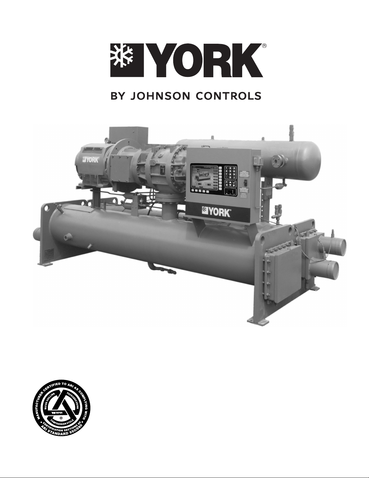
Model YS Rotary Screw Liquid Chillers
Design Level E
100 thru 675 tons
(315 thru 2375 KW)
r-22 and r-134a
Page 2

TABLE OF CONTENTS
PAGE
INTRODUCTION ........................................................... 3
RATINGS ....................................................................... 4
OPTIVIEW CONTROL CENTER ................................... 5
MECHANICAL SPECIFICATIONS ................................ 13
ACCESSORIES & MODIFICATIONS ............................ 17
UNIT COMPONENTS ................................................... 19
APPLICATION DATA ..................................................... 20
DIMENSIONS – STD ..................................................... 28
S0-S3 Compressor .................................................... 28
S4 & S5 Compressor ............................................... 29
Compact Water Box Nozzle Arrangements ............... 30
Floor Layout .............................................................. 31
Cooler Nozzle Arrangements .................................... 32
Condenser Nozzle Arrangements ............................. 34
WEIGHTS – STD ........................................................... 36
DIMENSIONS – METRIC .............................................. 38
S0-S3 Compressor .................................................... 38
S4 & S5 Compressor ............................................... 39
Compact Water Box Nozzle Arrangements ............... 40
Floor Layout .............................................................. 41
Cooler Nozzle Arrangements .................................... 42
Condenser Nozzle Arrangements ............................. 44
WEIGHTS – METRIC .................................................... 46
GUIDE SPECIFICATIONS ............................................ 48
METRIC CONVERSION TABLES ................................. 53
LIST OF TABLES
TABLE
NO.
1 Water Flow Rate Limits.................. 20
2 Motor Voltage Variations ................ 23
3 60 Hz Electrical Data ..................... 25
4 Motor Starters ................................ 25
5 50 Hz Electrical Data ..................... 26
6 Available Compressor/Shell/
Motor Combinations
(R-22 & R-134a) ............................ 26
7 Available Compressor/Shell/
Motor Combinations
(50 Hz, R-134a Only) ..................... 27
PAGE
NOMENCLATURE
The model number denotes the following characteristics of the unit:
YS BB BA S0 – CF E S
Model
Cooler Code
Condenser Code
Compressor Code
Power Supply:
– for 60 Hz
5 for 50 Hz
2 JOHNSON CONTROLS
Special Features
Design Level
Motor Code
Page 3

Introduction
FORM 160.80-EG1 (808)
The YORK Millennium YS Chiller offers a complete com-
bination of features for total owner satisfaction.
MATCHED COMPONENTS MAXIMIZE EFFICIENCY
Actual chiller efciency cannot be determined by analyzing
the theoretical efciency of any one chiller component.
It requires a specic combination of heat exchanger,
compressor, and motor performance to achieve the lowest system kW/Ton. YORK Millennium chiller technology
matches chiller system components to provide maximum
chiller efciency under actual – not just theoretical – operating conditions.
REAL-WORLD ENERGY PERFORMANCE
Johnson Controls pioneered the term “Real-World Energy”
to illustrate the energy-saving potential of focusing on
chiller performance during off-design conditions. Off-design is not only part load, but full load operation as well,
with reduced entering condenser water temperatures
(ECWTs). This is where chillers operate 99% of the time,
and where operating costs add up.
The YS Millennium chillers are the only chillers designed
to operate on a continuous basis with cold ECWT and full
condenser ow at all load points, taking full advantage of
Real-World conditions. This type of operation benets the
cooling tower as well; reducing cycling of the fan motor
and ensuring good coverage of the cooling ll.
YORK Millennium chillers offer the most efcient Real-
World operation of any chiller, meaning lower operating
costs and an excellent return on your chiller investment.
Insurance companies that offer policies on large air conditioning equipment often consider air-cooled motors a sig-
nicant advantage over hermetic refrigerant cooled units.
HIGH-EFFICIENCY HEAT EXCHANGERS
Millennium chiller heat exchangers offer the latest technology in heat transfer surface design to give you maxi-
mum efciency and compact design. Water-side and
refrigerant-side design enhancements minimize both
energy consumption and tube fouling.
FACTORY PACKAGING REDUCES FIELD LABOR
COSTS
YORK Millennium screw chillers are designed to keep
installation costs low. Where installation access is not a
problem, the unit can be shipped completely packaged,
requiring minimal piping and wiring to complete the installation.
For those units utilizing a factory installed Solid-State
Starter, the three power leads provide all power to the
chiller and its auxiliaries.
TAKE ADVANTAGE OF COLDER COOLING TOWER
WATER TEMPERATURES
YORK Millennium screw chillers are designed to take full
advantage of colder cooling tower water temperatures,
which are naturally available during most operating hours.
Considerable energy savings are available by letting tower
water temperature drop, rather than articially holding it
above 75°F (23.9°C), especially at low load, as some
chillers require.
OPEN DRIVE DESIGN
Hermetic-motor burnout can cause catastrophic damage
to a chiller. The entire chiller must be cleaned, and the
refrigerant replaced. YORK Millennium screw chillers
eliminate this risk by utilizing air-cooled motors. Refrigerant never comes in contact with the motor, preventing
contamination of the rest of the chiller.
U.L. ACCEPTANCE – YOUR ASSURANCE OF RELIABILITY
YORK Millennium screw chillers are approved for listing
by Underwriter’s Laboratories for the United States and
Canada. Recognition of safety and reliability is your assurance of trouble-free performance in day-to-day building
operation.
3JOHNSON CONTROLS
Page 4

Ratings
Rated in accordance with the latest
issue of ARI Standard 550/590.
ARI CERTIFICATION PROGRAM
The performance of YORK Millennium chillers is certied
to the Air Conditioning and Refrigeration Institute (ARI)
complying with the certication sections of the latest issue
of ARI Standard 550/590. Under this Certication Pro-
gram, chillers are regularly tested in strict compliance with
this Standard. This provides an independent, third-party
verication of chiller performance.
COMPUTERIZED PERFORMANCE RATINGS
Each chiller is custom-matched to meet the individual
building load and energy requirements. A large number
of standard heat exchangers and pass arrangements are
available to provide the best possible match.
It is not practical to provide tabulated performance for
each combination, as the energy requirements at both full
and part- load vary signicantly with each heat exchanger
and pass arrangement. Computerized ratings are avail-
able through each Johnson Controls sales ofce. These
ratings can be tailored to specic job requirements, and
are part of the ARI Certication Program.
OFF-DESIGN PERFORMANCE
Since the vast majority of its operating hours are spent
at off-design conditions, a chiller should be chosen not
only to meet the full-load design, but also for its ability to
perform efciently at lower loads and lower tower water
temperatures. It is not uncommon for chillers with the
same full-load KW/TON to have an operating cost difference of over 10% due to part-load operation.
Part-load information can be easily and accurately generated by computer. And because it is so important to an
owner’s operating budget, this information is now stan-
dard within the ARI Certication Program in the form of
an Integrated Part-Load Value (IPLV), and Non-Standard
Part-Load Value (NPLV).
The IPLV / NPLV formulas from ARI Standard 550/590
closely track chiller operations, and provide a more accurate indication of chiller performance than the previous IPLV / APLV formula. A more detailed analysis must
take into account actual building load proles, and local
weather data. Part-load performance data should be ob-
tained for each job using its own design criteria.
4 JOHNSON CONTROLS
Page 5
OptiView Control Center
FORM 160.80-EG1 (808)
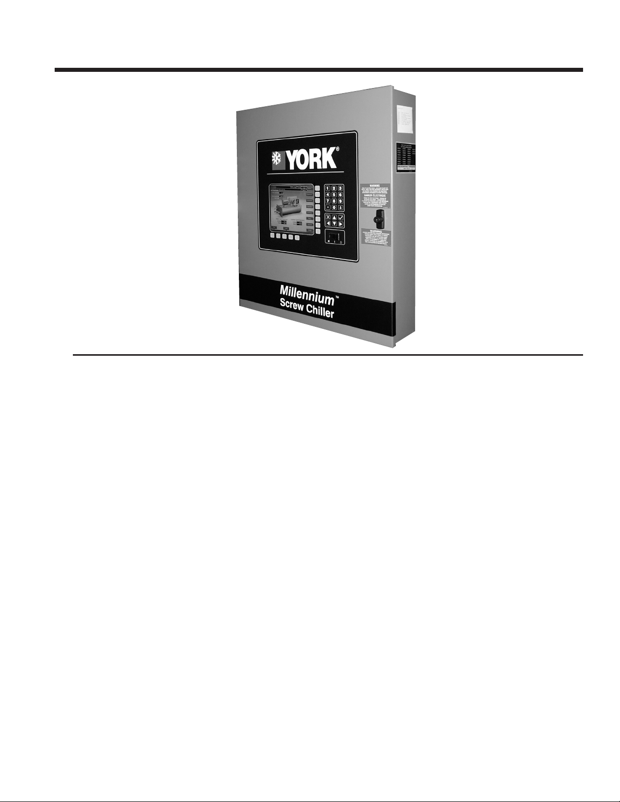
OPTIVIEW CONTROL CENTER
The YORK OptiView Control Center, furnished as standard
on each chiller, provides the ultimate in efciency, monitoring, data recording, chiller protection and operating ease.
The control center is a factory mounted, wired, and tested
state-of-the-art microprocessor based control system for
R-134a or R-22 screw chillers. The panel is congured
with a 10.4 inch diagonal color Liquid Crystal Display
(LCD) surrounded by “soft” keys, which are redened with
one keystroke based on the screen display at that time.
This revolutionary development makes chiller operation
quicker and easier than ever before. Instead of requiring
keystroke after keystroke to hunt for information on a small
monochrome LCD screen, a single button reveals a wide
array of information on a large, full-color illustration of the
appropriate component, which makes information easier
to interpret. This is all mounted in the middle of a keypad
interface and installed in a locked enclosure.
The LCD display allows graphic animated display of the
chiller, chiller sub-systems and system parameters; this
allows the presentation of several operating parameters
at once. In addition, the operator may view a graphical
representation of the historical operation of the chiller as
well as the present operation. A Status Bar is displayed
at all times on all screens. It contains the System - Status
Line and Details Line, the Control Source, Access Level,
Date and Time. All date representations and calculations
use four digits for the year to provide Year 2000 compliance.
During the Start Sequence and System Lockout Delay, the
system status will include a countdown timer indicating the
time remaining. The control panel is compatible with the
YORK Solid State Starter (optional), Electro-mechanical
(E-M) starter, or any customer supplied E-M starter that
complies with the YORK R-1051 standard. The locations
of various chiller parameters are clearly marked and in-
structions for specic operations are provided. The panel
verbiage is available in other languages as an option, with
English always available. Data can be displayed in either
English or Metric units, plus keypad entry setpoints of 0.1
increments.
Security access is provided to prevent unauthorized access and/or a change of setpoints. This is accomplished
with three different levels of access and passwords for
each level. There are screens, displayed values, programmable setpoints and manual controls not shown available
to service the chiller. They are only displayed when logged
in at the service access level. The Advanced Diagnostics
and troubleshooting information for the chiller and the
panel is also included.
The panel is fused through a 1-1/2 or 2 KVA transformer
in the compressor motor starter to provide individual
over-current protected power for all controls. Numbered
terminal strips for wiring such as Remote Start/Stop,
Flow Switch, Chilled Water Pump and Local or Remote
Cycling Device are provided. The Panel also provides
eld interlocks that indicate the chiller status. These contacts include a Remote Mode Ready To Start, a Cycling
5JOHNSON CONTROLS
Page 6

OptiView Control Center - continued
Shutdown, a Safety Shutdown and a chiller Run Contact.
Pressure transducers sense system pressures and thermistors sense system temperatures. The output of each
transducer is a DC voltage that is analogous to the pressure input. The output of each thermistor is a DC voltage
that is analogous to the temperature it is sensing.
Setpoints can be changed from a remote location via
0-10VDC, 4-20mA, contact closures or through serial
communications. The adjustable remote reset range [up
to 20°F (11.1°C)] provides exible, efcient use of remote
signal depending on reset needs. Serial data interface
to the YORK ISN Building Automation System (BAS) is
through the General Protocol Interface Card (GPIC), which
can be mounted inside the Control Center.
This printed circuit board requests the required data from
the Micro Board and makes it available for the YORK
ISN network. This optional board is available through the
Johnson Controls BAS group. The operating program
is stored in non-volatile memory (EPROM) to eliminate
chiller failure due to AC power failure/battery discharge.
Programmed setpoints are retained in lithium batterybacked RTC memory for 11 years minimum.
Smart Freeze Point Protection can operate the chiller as
low as 36°F (2.22°C) leaving chilled water temperature,
without nuisance trips on Low Water Temperature. The
sophisticated program and sensor monitors the chiller water temperature to prevent freeze-up. Each programmable
point has a pop-up screen with the allowable ranges, so
the chiller cannot be programmed to operate outside of
its design limits.
When power is applied to the chiller, the HOME screen
is displayed. This screen displays a visual representation
of the chiller and a collection of data detailing important
operations and parameters. When the chiller is running,
the ow of chilled liquid is animated by the alternating
shades of color moving in and out of the pipe nozzles. The
primary values that need to be monitored and controlled
are shown on this screen. They are as follows:
Display Only:
• Chilled Liquid Temperature – Leaving
• Chilled Liquid Temperature – Return
• Condenser Liquid Temperature – Return
• Condenser Liquid Temperature – Leaving
• Motor Run (LED)
• % Full Load Amps
• Operating Hours
With the “soft” keys the operator is only one touch away
from the 8 main screens that allow access to the major
information and components of the chiller. The 8 screens
are the SYSTEM, EVAPORATOR, CONDENSER, COM-
PRESSOR, OIL SUMP, MOTOR, SETPOINTS, and the
HISTORY. Also on the Home Screen is the ability to LOG
IN, LOG OUT and PRINT. Log In and Log Out is the means
by which different security levels are accessed.
The SYSTEM screen gives a general overview of common
chiller parameters for both shells. This is an end view of
the chiller with a 3-D cutaway of both the shells. The following can be viewed from this screen:
Thermal ice storage systems are based on the concept
of using off-peak, lower cost electricity to build ice for
handling the cooling load during peak hours. The most
efcient way to build ice is to maximize chiller load and
minimize run time. Standard chiller control systems are not
designed for this operating mode. In a typical application,
chillers will load and unload to maintain a leaving chilled
liquid setpoint. When the YORK YS chiller operates in the
thermal storage control mode, the unit will remain at 100%
load until the setpoint shutdown temperature is reached.
To add greater operating exibility and eliminate unnecessary chiller cycling, two different Low Water (Liquid)
Temperature Restart Thresholds can be programmed, one
for the ice mode and one for the standard cooling mode.
This control enhancement is standard on all YS chillers.
The chiller can also be left in the standard control mode
for temperatures ranging between 20 and 70°F (-6.7 and
21.1°C), for applications involving a process cooling duty
that requires leaving chilled liquid temperature setpoint
control.
6 JOHNSON CONTROLS
Display Only:
• Discharge Temperature
• Chilled Liquid Temperature – Leaving
• Chilled Liquid Temperature – Return
• Chilled Liquid Temperature – Setpoint
• Evaporator Pressure
• Evaporator Saturation Temperature
• Condenser Liquid Temperature – Leaving
• Condenser Liquid Temperature – Return
• Condenser Pressure
• Condenser Saturation Temperature
• Oil Temperature
• Differential Oil Pressure
• % Full Load Amps
• Current Limit
• Slide Valve Position
Page 7

FORM 160.80-EG1 (808)
The EVAPORATOR screen displays a cutaway view of
the chiller evaporator. All setpoints relating to the evaporator side of the chiller are maintained on this screen.
Animation of the evaporation process indicates whether
the chiller is presently in RUN condition (bubbling) and
liquid ow in the pipes is indicated by alternating shades
of color moving in and out of the pipes. Adjustable limits
on the low water temperature setpoints allow the chiller
to cycle on and off for greater efciency and less chiller
cycling. The chiller cycles off when the leaving chilled
water temperature is below setpoint and is adjustable
from 1°F (0.55°C) below to a minimum of 36°F (2.22°C).
Restart is adjustable from setpoint up to a max of 80°F
(44.4°C). The Panel will check for ow to avoid freezeup of the tubes. If ow is interrupted, shutdown will occur
after a minimum of two seconds. The following can also
be performed through this screen:
Display Only:
• Chilled Liquid Flow Switch (Open/Closed)
• Chilled Liquid Pump (Run/Stop)
• Evaporator Pressure
• Evaporator Saturation Temperature
• Return Chilled Liquid Temperature
• Leaving Chilled Liquid Temperature
• Evaporator Refrigerant Temperature
• Small Temperature Difference
• Leaving Chilled Liquid Temperature Setpoints –
Setpoint
• Leaving Chilled Liquid Temperature Setpoints –
Remote Range
• Leaving Chilled Liquid Temperature Setpoints –
Shutdown
• Leaving Chilled Liquid Temperature Setpoints –
Shutdown Offset
• Leaving Chilled Liquid Temperature Setpoints –
Restart
• Leaving Chilled Liquid Temperature Setpoints –
Restart Offset
• Ice Storage Active (LED)
Programmable:
• Local Leaving Chilled Liquid Temperature – Range
• Local Leaving Chilled Liquid Temperature – Setpoint
• Leaving Chilled Liquid Temperature Cycling Offset –
Shutdown
• Leaving Chilled Liquid Temperature Cycling Offset –
Restart
The CONDENSER screen displays a cutaway view of the
chiller condenser. The liquid ow is animated to indicate
ow through the condenser. All setpoints relating to the
condenser side of the chiller are maintained on this screen.
With the proper access level this screen also serves as a
gateway to controlling the Refrigerant Level. The following
can also be viewed through this screen:
Display Only:
• Leaving Condenser Liquid Temperature
• Return Condenser Liquid Temperature
• Condenser Pressure
• Condenser Saturation Temperature
• Small Temperature Difference
• High Pressure Switch (Open/Closed)
• Condenser Liquid Flow Switch
• Condenser Liquid Pump (Run/Stop)
Programmable:
• High Pressure Warning Threshold
• Freeze Warning (Enabled/Disabled)
• Freeze Time
The VARIABLE ORIFICE CONTROL screen, accessed
from the CONDENSER screen in SERVICE access level,
displays all of the applicable Variable Orice control
parameters and allows a Service Technician to program
the Delta P setpoint. The Low Evaporator Pressure and
Superheat Override LED’s are located on this screen.
A view of the liquid ow piping to the chiller condenser,
along with the solenoid ow control valve, is shown. The
following can also be performed through this screen:
Display Only:
• Condenser Pressure
• Evaporator Pressure
• Delta P (Condenser – Evaporator)
• Discharge Temperature
• Condenser Saturation Temperature
• Superheat Temperature
• Low Evaporator Override (LED)
• Superheat Override (LED)
Programmable:
• Delta P Setpoint
7JOHNSON CONTROLS
Page 8

OptiView Control Center - continued
The COMPRESSOR screen displays a cutaway view of
the chiller compressor, revealing the rotary screw, and
shows all conditions associated with the compressor. The
slide valve positioning is animated and with the proper
Access level, it can be manually controlled. Animation
of the compressor rotors indicates whether the chiller is
presently in a RUN condition. This screen also serves as
a gateway to sub-screens for calibrating the slide valve
or conguring the optional Hot Gas Bypass. From this
screen you can view the following:
Display Only:
• Differential Oil Pressure
• Oil Temperature
• Discharge Temperature
• Discharge Superheat
• Slide Valve Position
• Oil Return Solenoid (LED)
• Full Load Amps (E.M. Starter Only)
• Phase A, B, C Current (SSS Only)
Programmable:
• Slide Valve Load (Manual)
• Slide Valve Hold (Manual)
• Slide Valve Unload (Manual)
• Slide Valve Auto
• Max. Load Temperature
• Minimum Load FLA
• Minimum Load Control Source
The HOT GAS BYPASS screen, accessed from the COM-
PRESSOR screen, displays a pictorial of the bypass line
and solenoid valve location on the chiller. The Hot Gas
ON and OFF Setpoints are programmed on this screen
and system parameters pertinent to Hot Gas Bypass
operation are displayed. An LED illuminates when the
Hot Gas solenoid is ON. If the chiller is equipped with
the Hot Gas Bypass option, operation must be enabled
on the OPERATIONS screen. From this screen you can
perform the following:
Display Only:
• Slide Valve Position
• Return Chilled Liquid Temperature
• Leaving Chilled Liquid Temperature
• Hot Gas Solenoid (LED)
Programmable:
• On Setpoint
• Off Setpoint
The SLIDE VALVE CALIBRATION screen displays a
cutaway view of the chiller compressor, revealing the
rotary screw and slide valve and provides the capability
of calibrating the slide valve. From this screen, you can
perform the following:
Display Only:
• Slide Valve Loading (LED)
• Slide Valve Unloading (LED)
• Calibration Message
Programmable:
• Start Calibration
• Cancel Calibration
The OIL SEPARATOR screen displays a close-up view
of the chiller oil separator/sump and provides all the necessary setpoints for maintaining the Variable Speed Oil
Pump (VSOP). This screen also allows manual control
of the Frequency Command sent to the VSOP. From this
screen you can perform the following:
Display Only:
• Discharge Temperature
• Oil Sump Temperature
• Discharge Superheat
• Oil Pressure
• Filter Pressure
• Seal Pressure
• Differential Oil Pressure
• Differential Filter Pressure
• Differential Seal Pressure
• Offset Pressure
• Oil Return Solenoid (LED)
• Low Separator Oil Level (LED)
1. The MOTOR “soft” key on the HOME screen, when
pressed, shows a picture of either a YORK ElectroMechanical Starter or a Solid State Starter, depending
on chiller conguration. The Programmable pulldown
demand to automatically limit motor loading can be
used to minimize building demand charges. Pulldown
8 JOHNSON CONTROLS
Page 9

FORM 160.80-EG1 (808)
time period control over four hours, and verication of
time remaining in pulldown cycle from display readout.
Separate digital setpoint for current limiting between
30 and 100%.
The ELECTRO-MECHANICAL STARTER (E–M) screen
displays a picture of the starter and the following values.
The ones below are common among both offerings and the
values will be displayed on both types of starter screens.
From this screen you can perform the following:
Display Only:
• Motor Run (LED)
• Motor Current % Full Load Amps
• Current Limit Setpoints
• Pulldown Demand Time Left
Programmable:
• Local Motor Current Limit
• Pulldown Demand Limit
• Pulldown Demand Time
The SOLID STATE STARTER (SSS) screen displays a
picture of the starter and the following values, which are
displayed in addition to the common ones listed above.
From this screen, you can perform the following:
Display Only:
• Input Power
• kW Hours
• Starter Model
• Voltage – Phase A, B, C
• Current – Phase A, B, C
• Temperature – Phase A, B, C
ing, they can all be found on this screen. This screen also
serves as a gateway to a sub-screen for dening the setup
of general system parameters. From this screen you can
perform the following:
Display Only:
• Leaving Chilled Liquid Temperature – Setpoint
• Leaving Chilled Liquid Temperature Cycling –
Shutdown
• Leaving Chilled Liquid Temperature Cycling –
Restart
• Current Limit Setpoint
Programmable:
• Local Leaving Chilled Liquid Temperature – Range
• Local Leaving Chilled Liquid Temperature – Setpoint
• Leaving Chilled Liquid Temperature Cycling Offset –
Shutdown
• Leaving Chilled Liquid Temperature Cycling Offset –
Restart
• Remote Analog Input Range
• Local Motor Current Limit
• Pulldown Demand Limit
• Pulldown Demand Time
• Print
The SETUP is the top level of the general conguration parameters. It allows programming of the time and
date, along with specications as to how the time will be
displayed. In addition, the chiller conguration as determined by the micro board program jumpers and program
switches is displayed. From this screen you can perform
the following:
Programmable:
• Full Load Amps
• Voltage Range
• Starting Current
• Open SCR
• Shorted SCR
• kWH Reset
The SETPOINTS screen provides a convenient location
for programming the most common setpoints involved
in the chiller control. The Setpoints are shown on other
individual screens, but to cut down on needless search-
Display Only:
• Chilled Liquid Pump Operation (Displays Standard or
Enhanced)
• Refrigerant Selection (Displays R-22 or R-134a)
• Anti-Recycle (Displays Disabled or Enabled)
• Power Failure Restart (Displays Manual or Auto-
matic)
• Liquid Type (Displays Water or Brine)
Programmable:
• Set Date
• Set Time
• Clock (Enabled/Disabled)
• 12/24 Hour
9JOHNSON CONTROLS
Page 10

OptiView Control Center - continued
The following six subscreens can be accessed from
the SETUP screen:
The SCHEDULE screen contains more programmable
values than a normal display screen. Each programmable
value is not linked to a specic button; instead, the select
key is used to enable the cursor arrows and check key to
program the Start/Stop times for any day of the week up
to 6 weeks in advance. The user has the ability to dene
a standard set of Start/Stop times that are utilized every
week or specify exceptions to create a special week.
Programmable:
• Exception Start/Stop Times
• Schedule (Enable/Disable)
• Repeat Sunday Schedule
• Standard Week Start/Stop Times
• Reset All Exception Days
• Select
• Print
The USER screen allows denition of the language for the
chiller to display and denes the unit of measure.
Programmable:
• System Language
• English/Metric Units
• Output Interval
• Automatic Printer Logging (Enabled/Disabled)
• Print Type
• Print Report
• Print All Histories
The SALES ORDER screen allows denition of the order
parameters. Note: This information is loaded at the factory
or by the installation service technician.
Display Only
• Model Number
• Panel Serial Number
• Chiller Serial Number
• YORK Order Number
• System Information
• Condenser and Evaporator Design Load Information
• Nameplate Information
The OPERATIONS screen permits denition of param-
eters pertaining to operation of the chiller. What is dened
is whether the control of the chiller will be Local, Digital Remote, Analog Remote, Modem Remote or ISN Remote.
Programmable
• Control Source
The COMMS screen allows the user to dene communications parameters.
Programmable:
• Chiller ID
• COM 2 Baud Rate
• COM 2 Data Bit(s)
• COM 2 Parity Bit(s)
• COM 2 Stop Bit(s)
• Printer Baud Rate
• Printer Data Bit(s)
• Printer Parity Bit(s)
• Printer Stop Bit(s)
The PRINTER screen permits the user to dene communications Parameters for the Printer.
Display Only
• Time Remaining Until Next Print
Programmable
• Log Start Time
The HISTORY screen allows the user to browse through
the last ten faults; either safety or cycling shutdowns with
the conditions, while the chiller is running or stopped.
The faults are color coded for ease in determining
the severity at a glance, recording the date, time and
description. (See Display Messages for Color Code
meanings.)
Display Only
• Last Normal Shutdown
• Last Fault While Running
• Last Ten Faults
Programmable:
• Print History
• Print All Histories
By pressing the VIEW DETAILS key you will move to the
HISTORY DETAILS screen. From these screens you
are able to see an on-screen printout of all the system
parameters at the time of the selected shutdown.
10 JOHNSON CONTROLS
Page 11

FORM 160.80-EG1 (808)
Display Only:
• History Printout
Programmable:
• Page Up
• Page Down
• Print History
Also under the HISTORY screen is the TRENDING
screen, accessible by the key marked the same. On this
screen, up to six operator-selected parameters, selected
from a list of over 140, can be plotted in an X/Y graph
format. The graph can be customized to record points
once every second up to once every hour. There are
two types of charts that can be created: single screen,
or continuous screen. The single screen collects data for
one screen width (450 data points across the X-axis), then
stops. The continuous screen keeps collecting the data,
but the oldest data drops off the graph from left to right
at the next data collection interval. For ease of identication, each plotted parameter, title and associated Y-axis
labeling is color coordinated.
Display Only:
• This screen allows the user to view the graphical
trending of the selected parameters and is a gateway
to the graph setup screens.
• Data Point Min (1 - 6)
• Data Point Max (1 - 6)
The TREND COMMON SLOTS screen displays the Mas-
ter Slot Numbers List of the monitored parameters.
Display Only:
• Slot Numbers
Programmable:
• Page Up
• Page Down
• Print
DISPLAY MESSAGES
The Control Center continuously monitors the operating
system, displaying and recording the cause of any shutdowns (Safety, Cycling or Normal). The condition of the
chiller is displayed at the System Status line that contains
a message describing the operating state of the chiller;
whether it is stopped, running, starting or shutting down.
A System Details Line displays Warning, Cycling, Safety,
Start Inhibit and other messages that provide further
details of the Status Bar messages. Messages are colorcoded: Green – Normal Operations; Yellow – Warnings;
Orange – Cycling Shutdowns; and Red – Safety Shutdowns to aid in identifying problems quickly.
Programmable:
• Start
• Stop
• Y-axis
• X-axis
The TREND SETUP screen is used to congure the trend-
ing screen. The parameters to be trended are selected
from the Trend Common Slots screen, accessed from
the Slot Numbers button or the Master Slot Numbers
List found in the Operating Manual. The interval at which
all the parameters are sampled is selected under the
Collection Interval button. The data point minimum and
maximum values may be adjusted closer to increase
viewing resolution.
Programmable:
• Chart Type (select continuous or one screen)
• Collection Interval
• Select
• Data Point Slot Number (1 - 6)
Status messages include:
• System Ready To Start
• Cycling Shutdown – Auto Restart
• Safety Shutdown – Manual Restart
• Start Sequence Initiated
• System Run (with countdown timers)
• Start Inhibit
• Slide Valve Closing Before Shutdown
• System Lockout Delay
Run Messages include:
• Leaving Chilled Liquid Control
• Motor Pulldown Limit
• Motor – High Current Limit
Start Inhibit Messages include:
• Anti-Recycle XX min/sec.
• Slide Valve – Position >30%
• Motor Current >15% FLA
• LCSSS – High-Temperature Phase X - Stopped
11JOHNSON CONTROLS
Page 12

OptiView Control Center - continued
Warning Messages include:
• Real Time Clock Failure
• Setpoint Override
• Condenser – High Pressure Limit
• Evaporator – Low Pressure Limit
• Freeze Threat From Operating Chiller
• Freeze Threat, Condenser Flow Switch Open
• Low Discharge Superheat Limit
• Low Discharge Superheat Detected
• Maximum Load – Load Limit
• Minimum Load – Load Limit
• Oil – Dirty Filter
• Oil – High Temperature
• Slide Valve Uncalibrated
Routine Shutdown Messages Include:
• Remote Stop
• Local Stop
• Place Compressor Switch In Run Position
Cycling Shutdown Messages Include:
• Multiunit Cycling – Contacts Open
• System Cycling – Contacts Open
• Control Panel – Power Failure
• Leaving Chilled Liquid – Low Temperature
• Leaving Chilled Liquid – Flow Switch Open
• Condenser – Flow Switch Open
• Motor Controller – Contacts Open
• Motor Controller – Loss of Current
• Power Fault
• Control Panel – Schedule
Solid State Starter Only (LCSSS)
• Initialization Failed
• Serial Communications
• Requesting Fault Data
• Stop Contacts Open
• Power Fault
• Low Phase (X) Temperature Sensor
• Run Signal
• Invalid Current Scale Selection
• Phase Locked Loop
• Low Supply Line Voltage
• High Supply Line Voltage
• Logic Board Processor
• Logic Board Power Supply
• Phase Loss
Safety Shutdown Messages include:
• Evaporator – Low Pressure
• Evaporator – Low Pressure – Smart Freeze
• Evaporator – Transducer or Leaving Liquid Probe
• Evaporator – Transducer or Temperature Sensor
• Condenser – High Pressure Contacts Open
• Condenser – High Pressure
• Condenser – Pressure Transducer Out of Range
• Auxiliary Safety – Contacts Closed
• Discharge – High Temperature
• Discharge – Low Temperature
• Oil – High Temperature
• Oil – Low Differential Pressure
• Oil – Low Differential Seal Pressure
• Oil or Condenser Transducer Error
• Oil – Clogged Filter
• Oil – High Pressure
• Oil – Separator – Low Level
• Control Panel – Power Failure
• Watchdog – Software Reboot
Solid State Starter Only (LCSSS)
• Shutdown – Requesting Fault Data . . .
• High Instantaneous Current
• High Phase (X) Heatsink Temperature – Running
• 105% Motor Current Overload
• Motor or Starter – Current Imbalance
• Open SCR
• Phase Rotation
12 JOHNSON CONTROLS
Page 13

Mechanical Specications
FORM 160.80-EG1 (808)
STANDARD UNIT
General
The YORK Millennium YS Rotary Screw Chiller is completely factory-packaged, including evaporator, condenser,
sub-cooler, oil separator, compressor, motor, lubrication
system, control center and refrigerant isolation valves.
The factory package consists of a “leak tight” design. All
units ship as standard with a full charge of refrigerant
and oil. Units can also be shipped in sections (optional)
to accommodate job site requirements.
The services of a Johnson Controls factory-trained, eld
service representative are incurred to supervise or perform
the nal leak testing, charging, the initial start-up, and
concurrent operator instructions.
Compressor
The Frick Rotary Twin Screw Compressor is engineered
and constructed to meet the exact requirements of the
industrial refrigeration market. It utilizes state-of-the-art
technology to provide the most reliable and energy-ef-
cient compressor available at all operating conditions.
The compressor operates at 3750 RPM for 60 Hertz and
2975 RPM for 50 Hertz. The compressor housing is made
of cast iron, precision-machined to provide minimal clearance for the rotors. Compressor housing has a design
working pressure (DWP) of 300 PSIG (2068 kPa) minimum, and hydro-tested at 544 PSIG (3751 kPa).
provides fully modulating capacity control from 100% to
10% of full load. The slide valve is actuated by oil pressure,
controlled by external solenoid valves via the OptiView
Control Center.
Oil Separator
The oil separator is a horizontal design without moving
parts. Effective oil separation is achieved by gravity dropout of oil from the refrigerant gas as velocity decreases
upon entering the separator, and by mesh pads to provide
nal gas/oil separation before gas enters the condenser.
The oil separator is designed for 345 PSIG (2378 kPa)
design working pressure, tested at 517 PSIG (3565 kPa),
and stamped in accordance with ASME Boiler and Pressure Vessel Code, Section VIII - Division 1.
Each vessel has a refrigerant relief device(s) set at 300
PSIG (2068 kPa). In addition to the spring-loaded, re-seating-type relief valves sized for pressure vessel volume,
each unit is equipped with a rupture disk. This rupture
disk is able to relieve the entire pumping capacity of the
compressor if electronic safeties fail, providing protection for property and personnel. This device is set for
345 PSIG (2378 kPa). Alternatively, the shell side may
be designed to European Pressure Vessel Codes and
stamped in accordance with A.D. Merkblatter or other
European Pressure Vessel design code. When required
by the refrigeration safety code, each vessel has a dual
refrigerant relief device(s).
The rotors are manufactured from forged steel and use
asymmetric proles. The compressor incorporates a
complete anti-friction bearing design for reduced power
and increased reliability. Four separate cylindrical roller
bearings handle radial loads. Two 4-point angular contact
ball bearings handle axial loads. Together, they maintain
accurate rotor positioning at all pressure ratios, thereby
minimizing blow-by and maintaining efciency.
A check valve is installed in the compressor discharge
housing (suction housing for S4 and S5 compressor) to
prevent compressor rotor back spin because of system
refrigerant pressure gradients during shutdown.
The open-drive compressor shaft seal consists of precision ceramic seal faces, metallic bellows, rotating member,
PTFE ‘C’-Ring static seal, and multi-port oil injection ring.
The seal cavity is maintained at intermediate pressure
with its oil discharged to the oil drain from the compressor.
Combining intermediate pressure with direct oil injection
provides cool, non-foaming lubricant to the seal assuring
a longer lifespan.
Capacity Control
Capacity control is achieved by use of a slide valve which
Lubrication
The main unit oil reservoir is located in the oil separator.
The compressor also has an oil reservoir located at the
rotor bearings to provide lubrication during start-up, coat
down, and in the event of a power failure. During opera-
tion, system pressure differential provides proper oil ow
without the need of an auxiliary oil pump. This minimizes
energy consumption.
The chiller is shipped with a 3 Micron absolute oil lter,
ensuring a clean oil system and superior compressor
life. An external, replaceable cartridge oil lter is supplied
with manual isolation stop valves for ease of servicing.
An optional dual oil lter housing with isolation valves is
available on all units. This allows immediate switching
from one lter to the other, eliminating downtime during
lter changes. The off-line oil lter can be changed during
chiller operation.
A 500 watt (115 volt - 1-phase - 60/50Hz) immersion
oil heater is located in the oil separator reservoir, tem-
perature actuated to efciently remove refrigerant from
the oil. Oil heater power supply is factory wired from
the control panel. A factory-piped refrigerant-cooled oil
13JOHNSON CONTROLS
Page 14

Mechanical Specications - continued
cooler is provided as standard. No auxiliary water piping is required. An oil eductor automatically removes oil
which may have migrated to the evaporator and returns
it to the compressor.
MOTOR DRIVELINE
The compressor motor is an open drip-proof, squirrel
cage, induction type constructed to Johnson Controls
design specications. 60 Hertz motors operate at 3750
RPM; 50 Hertz motors operate at 2975 RPM. The open
motor is provided with a D-Flange and is factory-mounted
to a cast-iron adaptor mounted on the compressor. This
unique design allows the motor to be rigidly coupled to
the compressor to provide factory alignment of motor and
compressor shafts.
Motor drive shaft is directly connected to the compressor
shaft with a exible disc coupling. Coupling has all metal
construction with no wearing parts to assure long life.
Additionally, no lubrication is required – providing low
maintenance.
For units utilizing remote electro-mechanical starters,
a large steel terminal box with gasketed front access
cover is provided for eld connected conduit. There are
six terminals (three for medium voltage) brought through
the motor casing into the terminal box. Jumpers are furnished for three-lead type of starting. Motor terminal lugs
are not furnished. Overload/overcurrent transformers are
furnished with all units. For units furnished with factorypackaged Solid State Starters, refer to the Accessories
and Modications section (page 17).
HEAT EXCHANGERS
Shells
Evaporator and condenser shells are fabricated from
rolled carbon steel plates with fusion welded seams.
Carbon steel tube sheets, drilled and reamed to accommodate the tubes, are welded to the end of each shell.
Intermediate tube supports are fabricated from carbon
steel plates, drilled and reamed to eliminate sharp edges,
and spaced no more than four feet apart. The refrigerant
side of each shell is designed, tested, and stamped in
accordance with ASME Boiler and Pressure Vessel Code,
Section VIII – Division I, or other pressure vessel code
as appropriate.
Tubes
Heat exchanger tubes are state-of-the-art, high efciency,
externally and internally enhanced type to provide optimum performance. Tubes in both the evaporator and
condenser are 3/4” O.D. copper alloy and utilize the
“skip-n” design, providing a smooth internal and external
surface at each intermediate tube support. This provides
extra wall thickness (up to twice as thick) and non-work
hardened copper at the support location, extending the
life of the heat exchangers. Each tube is roller expanded
into the tube sheets providing a leak-proof seal, and is
individually replaceable.
Evaporator
The evaporator is a shell and tube, ooded type heat exchanger. A distributor trough provides uniform distribution
of refrigerant over the entire shell length to yield optimum
heat transfer. A suction bafe or aluminum mesh eliminators are located above the tube bundle to prevent liquid
refrigerant carryover into the compressor. A 1-1/2” liquid
level sight glass is conveniently located on the side of the
shell to aid in determining proper refrigerant charge. The
evaporator shell contains a dual refrigerant relief valve
arrangement set at 180 PSIG (1241 kPa); or single-relief
valve arrangement, if the chiller is supplied with the optional refrigerant isolation valves. A 1” refrigerant charging
valve is provided.
Condenser
The condenser is a shell and tube type, with a discharge
gas bafe to prevent direct high velocity impingement on
the tubes. The bafe is also used to distribute the refrigerant gas ow properly for most efcient heat transfer.
An integral sub-cooler is located at the bottom of the
condenser shell providing highly effective liquid refriger-
ant subcooling to provide the highest cycle efciency. The
condenser contains dual refrigerant relief valves set at
235 PSIG (1620 kPa).
Water Boxes
The removable water boxes are fabricated of steel. The
design working pressure is 150 PSIG (1034 kPa) and the
boxes are tested at 225 PSIG (1551 kPa). Integral steel
water bafes are located and welded within the water box
to provide the required pass arrangements. Stub-out water
nozzle connections with ANSI/AWWA C-606 grooves are
welded to the water boxes. These nozzle connections
are suitable for ANSI/AWWA C-606 couplings welding or
anges, and are capped for shipment. Plugged 3/4” drain
and vent connections are provided in each water box.
REFRIGERANT FLOW CONTROL
The YS Chiller is equipped with a refrigerant metering
device consisting of a xed orice and bypass solenoid
valve, which automatically adjusts to all real-world operating conditions. This control ensures proper refrigerant ow
to the evaporator over a wide range of operating conditions, including thermal storage applications and chilled
water reset. Valve operation is programmable and can
be customized for a specic application via the control
panel keyboard.
14 JOHNSON CONTROLS
Page 15

FORM 160.80-EG1 (808)
REFRIGERANT ISOLATION
The condenser shell serves as a refrigerant receiver
to store the system charge during servicing. Manually
operated isolation valves are located at the inlet and
outlet of the condenser. Valves are also provided to facilitate removal of the refrigerant from the system when
necessary.
OPTIVIEW CONTROL CENTER
General
The chiller is controlled by a stand-alone microprocessorbased control center. The chiller control panel provides
control of chiller operation and monitoring of chiller sensors, actuators, relays and switches.
Control Panel
The control panel includes a 10.4 inch diagonal color liquid
crystal display (LCD) surrounded by “soft” keys, which
are redened based on the screen displayed at that time,
mounted in the middle of a keypad interface and installed
in a locked enclosure. The screen details all operations
and parameters, using a graphical representation of the
chiller and its major components. Panel verbiage is available in other languages as an option with English always
available. Data can be displayed in either English or Metric
units. Smart Freeze Point Protection will run the chiller at
36°F (2.22°C) leaving chilled water temperature and not
experience nuisance trips on low water temperature. The
sophisticated program and sensor monitors the chiller water temperature to prevent freeze-up. When needed, Hot
Gas Bypass is available as an option. The panel displays
countdown timer messages so the operator knows when
functions are starting and stopping. Every programmable
point has a pop-up screen with the ranges included, so
the chiller can not be programmed to operate outside of
its design limits.
The control panel includes a thermal ice storage control
mode which enhances system performance during ice
building operation when compared to standard cooling
logic. In thermal storage control mode, the chiller will
operate at 100% load until the setpoint shutdown tem-
perature is reached. To add greater operating exibility
and eliminate unnecessary chiller cycling, two different
Low Water (Liquid) Temperature Restart Thresholds are
programmable, one for the ice mode and one for the standard cooling mode. The chiller has the capability to remain
in the standard control mode for temperatures between
20°F to 70°F (–6.7°C to 21.1°C) for applications involving
a process cooling duty that requires leaving chilled liquid
temperature setpoint control.
The chiller control panel also provides:
1. System operating information including:
• Return and Leaving Chilled Water Temperature
• Return and Leaving Condenser Water Tem
perature
• Evaporator and Condenser Saturation Tem
perature
• Oil Pressure at Compressor and Oil Filter
Differential
• Percent Motor Current
• Evaporator and Condenser Saturation Tem
perature
• Compressor Discharge Temperature
• Oil Temperature
• Percent Slide Valve Position
• Operating Hours
• Number of Unit Starts
2. Digital Programming of Setpoints Through The Universal Keypad Including:
• Leaving Chilled Water Temperature
• Percent Current Limit
• Pull-Down Demand Limiting
• Six-Week Schedule For Starting and Stopping
The Chiller, Pumps and Tower
• Remote Reset Temperature Range
3. Status Messages Indicating:
• System Ready To Start
• System Running
• System Coastdown
• System Safety Shutdown – Manual Restart
• System Cycling Shutdown – Auto Restart
• System Prelube
• Start Inhibit
4. The text displayed within the system status and sys-
tem details eld is displayed as a color-coded message to indicate severity: red for safety fault; orange
for cycling faults; yellow for warnings; and green for
normal messages.
5. Safety shutdowns are enunciated through the display
and the status bar, and consist of system status, system details, day, time, cause of shutdown, and type of
restart required. Safety shutdowns with a xed speed
drive include:
• Evaporator – Low Pressure
• Evaporator – Low Pressure - Smart Freeze
• Evaporator – Transducer or Leaving Liquid
Probe
15JOHNSON CONTROLS
Page 16

Mechanical Specications - continued
• Evaporator – Transducer or Temperature Sen sor
• Condenser – High Pressure Contacts Open
• Condenser – High Pressure
• Condenser – Pressure Transducer Out Of
Range
• Auxiliary Safety – Contacts Closed
• Discharge – High Temperature
• Discharge – Low Temperature
• Oil – High Temperature
• Oil – Low Differential Pressure
• Oil – Low Differential Seal Pressure
• Oil Or Condenser Transducer Error
• Oil – Clogged Filter
• Oil – High Pressure
• Oil – Separator – Low Level
• Control Panel – Power Failure
• Watchdog – Software Reboot
5.1 Safety shutdowns with a Solid State Starter (LCSSS)
include:
• Shutdown - Requesting Fault Data...
• High Instantaneous Current
• High Phase (X) Heatsink Temperature - Run
ning
• 105% Motor Current Overload
• Motor Or Starter – Current Imbalance
• Phase (X) Shorted SCR
• Open SCR
• Phase Rotation
6. Cycling shutdowns enunciated through the display
and the status bar, and consists of system status,
system details, day, time, cause of shutdown, and
type of restart required.
Cycling shutdowns with a fixed speed drive in-
clude:
• Multiunit Cycling - Contacts Open
• System Cycling - Contacts Open
• Control Panel - Power Failure
• Leaving Chilled Liquid – Low Temperature
• Leaving Chilled Liquid – Flow Switch Open
• Condenser - Flow Switch Open
• Motor Controller – Contacts Open
• Motor Controller – Loss Of Current
• Power Fault
• Control Panel – Schedule
6.1 Cycling shutdowns with a Solid State Starter (LCSSS)
include:
• Initialization Failed
• Serial Communications
• Requesting Fault Data
• Stop Contacts Open
• Power Fault
• Low Phase (X) Temperature Sensor
• Run Signal
• Invalid Current Scale Selection
• Phase Locked Loop
• Low Supply Line Voltage
• High Supply Line Voltage
• Logic Board Processor
• Logic Board Power Supply
• Phase Loss
7. Security access to prevent unauthorized change of
setpoints, to permit local or remote control of the
chiller, and to allow manual operation of the prerotation vanes and oil pump. Access is through ID and
password recognition, which is dened by three
different levels of user competence: view, operator,
and service.
8. Trending data with the ability to customize points of
once every second to once every hour. The panel
will trend up to 6 different parameters from a list of
over 140, without the need of an external monitoring
system.
9. The operating program is stored in non-volatile
memory (EPROM) to eliminate reprogramming the
chiller due to AC power failure or battery discharge.
Programmed setpoints are retained in lithium battery-backed RTC memory for a minimum of 11 years
with power removed from the system.
10. A fused connection through a transformer in the
compressor motor starter to provide individual
over-current protected power for all controls.
11. A numbered terminal strip for all required eld interlock wiring.
12. An RS-232 port to output all system operating data,
shutdown/cycling message, and a record of the last
10 cycling or safety shutdowns to a eld-supplied
printer. Data logs to a printer at a set programmable
interval. This data can be pre-prograrnmed to print
from 1 minute to 1 day.
13. The capability to interface with a building automation
16 JOHNSON CONTROLS
Page 17

FORM 160.80-EG1 (808)
system to provide:
• remote chiller start and stop
• remote leaving chilled liquid temperature adjust
• remote current limit setpoint adjust
• remote ready to start contacts
• safety shutdown contacts
• cycling shutdown contacts
• run contacts
CODES AND STANDARDS
• ASME Boiler and Pressure Vessel Code – Section
Vlll Division 1.
• ARI Standard 550/590
• c/U.L. – Underwriters Laboratory
• ASHRAE 15 – Safety Code for Mechanical Refrigeration
• ASHRAE Guideline 3 – Reducing Emission of Halogenated Refrigerants in Refrigeration and Air-Conditioning Equipment and Systems
• NEC – National Electrical Code
• OSHA – Occupational Safety and Health Act
• A.D. Merkblatter
ISOLATION MOUNTING
The unit is provided with four vibration isolation mounts
consisting of 1” (25.4 mm) thick neoprene isolation pads
for eld mounting under the steel mounting pads located
on the tube sheets.
REFRIGERANT CONTAINMENT
The standard unit has been designed as a complete and
compact factory packaged chiller. As such, it has mini-
mum joints from which refrigerant can leak. The entire
assembly has been thoroughly leak tested at the factory
prior to shipment. The YORK chiller includes service
valves conveniently located to facilitate transfer of refrigerant to a remote refrigerant storage/recycling system.
Optional condenser isolation valves permit storage of the
charge in the condenser.
PAINT
Exterior surfaces are protected with one coat of Carib-
bean blue, durable alkyd-modied, vinyl enamel, ma-
chinery paint.
17JOHNSON CONTROLS
Page 18

Accessories and Modications
SOLID STATE STARTER
The Solid State Starter is a reduced voltage starter that
controls and maintains a constant current ow to the motor
during startup. It is compact and mounted on the chiller at
the motor terminals. Power and control wiring is factory
supplied. Available for 200-600 volts, the starter enclosure
is NEMA-1 with a hinged access door with lock and key.
Electrical lugs for incoming power wiring are provided.
Standard features include: digital readout at the OptiView
Control Center of the following:
Display Only:
• 3-phase voltage A, B, C
• 3-phase current A, B, C
• Input power (kW)
• kW Hours
• Starter Model
• Motor Run (LED)
• Motor Current % Full Load Amps
• Current Limit Setpoints
• Pulldown Demand Time Left
Programmable:
• Local Motor Current Limit
• Pulldown Demand Limit
• Pulldown Demand Time
Other features include: low line voltage; 115-volt control
transformer; three-leg sensing overloads; phase rotation
and single-phase failure protection; high temperature
safety protection; motor current imbalance and undervoltage safeties; open and close SCR protection; momentary
power interruption protection. The LCSSS is cooled by a
closed-loop, fresh water circuit consisting of a water-towater heat exchanger and 1/25 HP circulating pump. All
interconnecting water piping is factory installed and rated
for 150 PSIG working pressure. Optional unit-mounted
circuit breaker includes ground fault protection and
provides 65,000 amp short-circuit withstand rating in accordance with UL Standard 508. A non-fused disconnect
switch is also available. Both options are padlockable.
BAS REMOTE CONTROL
A communication interface permitting complete exchange
of chiller data with any BAS system is available with
optional ISN translator. ISN translator also allows BAS
system to issue commands to the chiller to control its
operation. ISN translators come in two models, controlling
up to four chillers and eight chillers respectively.
FACTORY INSULATION OF COOLER
Factory-applied thermal insulation of the exible, closed-
cell plastic type, 3/4” (19mm) thick is attached with va-
por-proof cement to the evaporator shell, ow chamber,
evaporator tube sheets, suction connection, and (as
necessary) to the auxiliary tubing. Not included is the
insulation of water boxes and nozzles. This insulation
will normally prevent condensation in environments with
relative humidities up to 75% and dry bulb temperatures
ranging from 50° to 90°F (10° to 32°C). 1-1/2” (38mm)
thick insulation is also available for relative humidities up
to 90% and dry bulb temperatures ranging from 50° to
90°F (10° to 32°C).
WATER FLANGES
Four 150 Ib. ANSI raised-face anges, for condenser and
evaporator water connections, are factory welded to water
nozzles. Companion anges, bolts, nuts and gaskets are
not included.
SPRING ISOLATION MOUNTING
Spring Isolation mounting is available instead of standard
isolation mounting pads when desired. Four level-adjusting/spring-type vibration isolator assemblies with non-skid
pads are provided with mounting brackets for eld installation. Isolators are designed for one-inch (25.4 mm)
deection.
WATER FLOW SWITCHES
Paddle-type, vapor-proof water ow switches suitable
for 150 psig (1034 KPa) DWP for chilled and condenser
water circuits. Switch for 115V-1-50/60 Hz service. A
chilled water ow switch is required. Condenser water
ow switch is optional.
SEQUENCE CONTROL KIT
For two, three or four units with chilled water circuits connected in series or parallel, the kit consists of return water
thermostat, lead-lag selector switch for sequence starting,
and time delay relay, with NEMA-1 enclosures, designed
for 115V-1-50/60 Hz.
18 JOHNSON CONTROLS
Page 19

FORM 160.80-EG1 (808)
STARTER – FIELD INSTALLED
A eld installed, electro-mechanical compressor motor
starter is available, selected for proper size and type for
job requirements and in accordance with Johnson Controls
Engineering Standard R-1079 for Starters.
MARINE WATER BOXES
Marine water boxes allow service access for cleaning of
the heat exchanger tubes without the need to break the
water piping. Bolted-on covers are arranged for convenient access. ANSI/AWWA C-606 nozzle connections are
standard; anges are optional. Marine water boxes are
available for condenser and/or evaporator.
KNOCK-DOWN SHIPMENT
The chiller can be shipped knocked-down into major
assemblies (evaporator, condenser, driveline, etc.) as
required to rig into tight spaces. This is particularly convenient for existing buildings where equipment room access
does not allow rigging a factory packaged chiller.
REFRIGERANT STORAGE/RECYCLING SYSTEM
A refrigerant storage/recycling system is a self-contained
package consisting of a refrigerant compressor with oil
separator, storage receiver, water-cooled condenser, lter
drier and necessary valves and hoses to remove, replace
and distill refrigerant. All necessary controls and safety
devices are a permanent part of the system. Typically not
required if unit isolation valves are provided.
19JOHNSON CONTROLS
Page 20
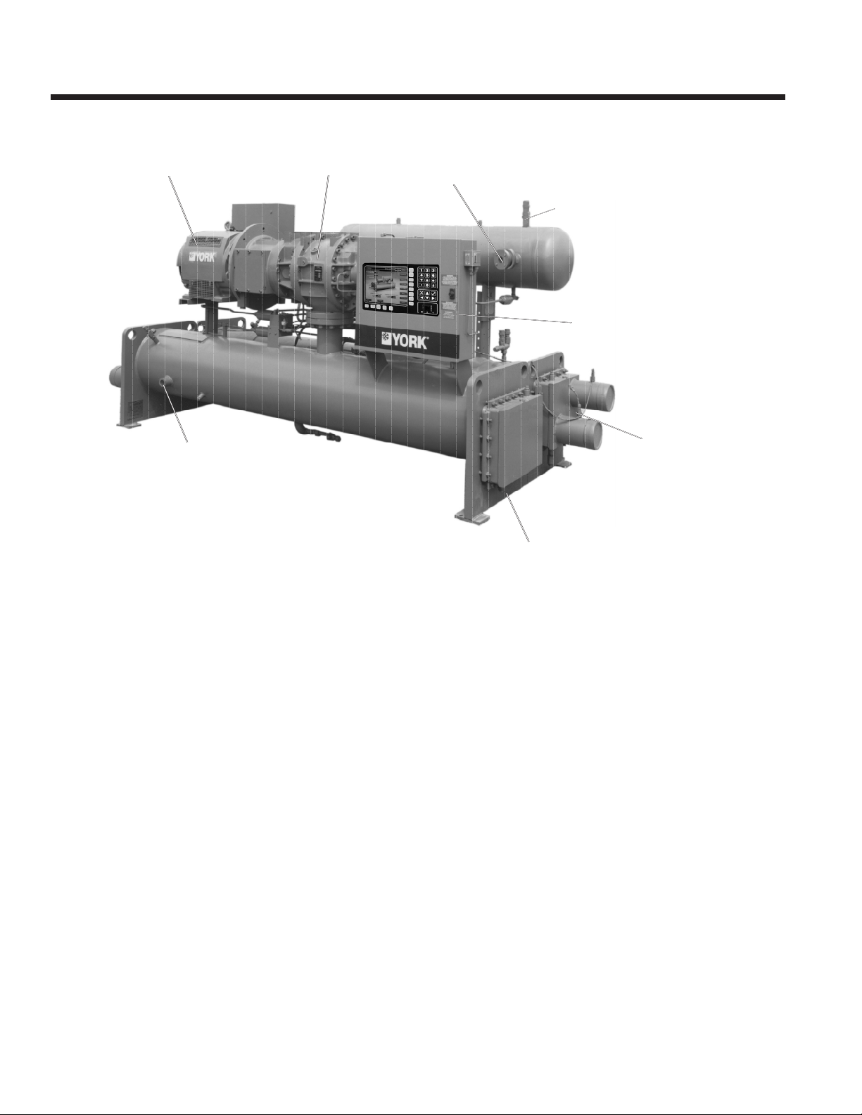
Unit Components
20 JOHNSON CONTROLS
Page 21

OIL SEPARATOR
FORM 160.80-EG1 (808)
MOTOR
TERMINAL
BOX
REAR VIEW
29040A
CONDENSER
21JOHNSON CONTROLS
Page 22
Application Data
The following is a user’s guide in the application and
installation of Millennium Chillers, and will ensure the reli-
ability and trouble-free life for which this equipment was
designed. While this guide is directed towards normal,
water-chilling applications, the Johnson Controls sales
representatives can provide complete recommendations
on other types of applications.
Location
Millennium Chillers are virtually vibration-free and generally can be located at any level in a building where
the construction will support the total system operating
weight.
The unit site must be a oor, mounting pad or foundation
which is level within 1/4” (6.4 mm) and capable of supporting the operating weight of the chiller.
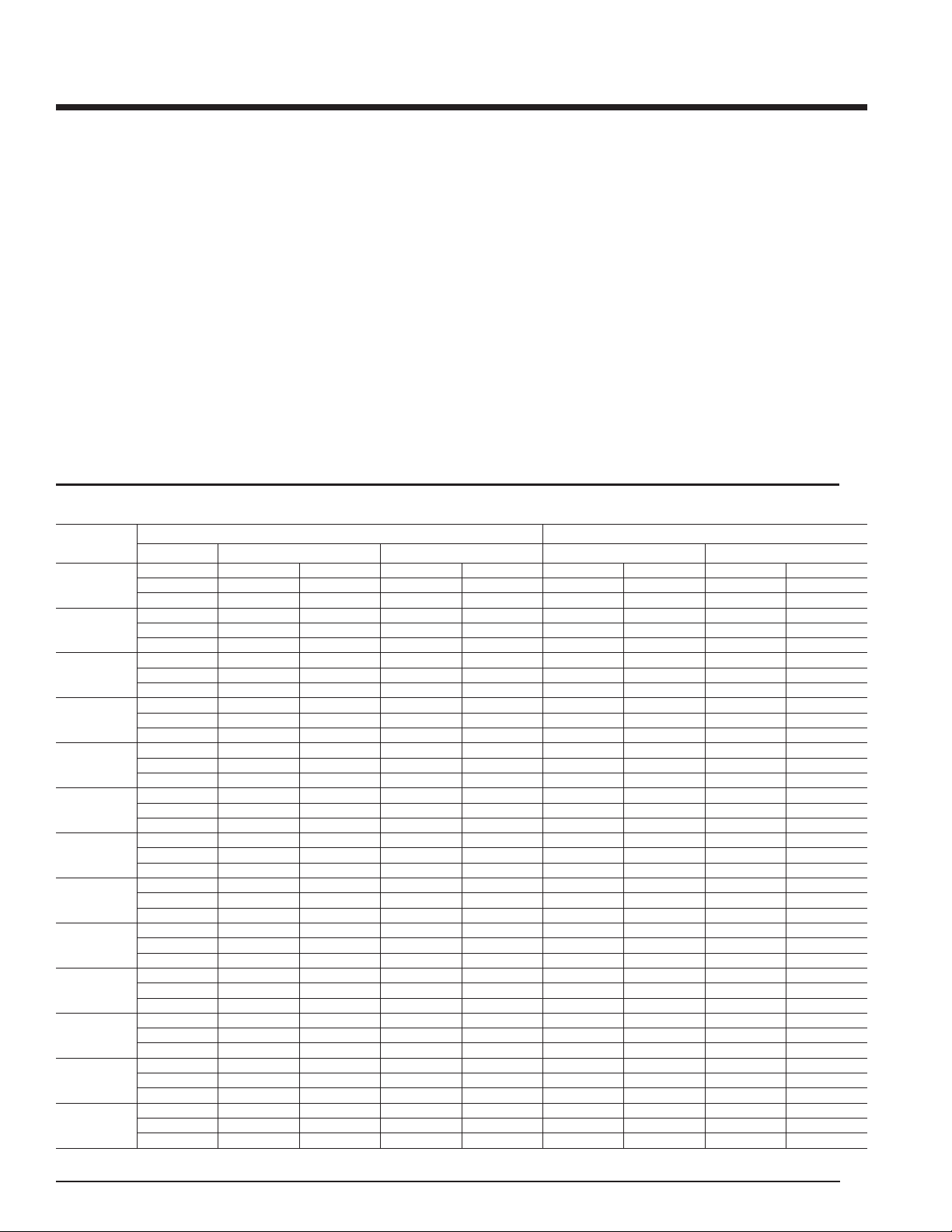
TABLE 1 – WATER FLOW RATE LIMITS – GPM (L/s)
shELL
CodE
Ba
BB
Ca
CB
da
dB
dC
Ea
EB
EC
Fa
FB
FC
Pass MInIMuM MaXIMuM MInIMuM MaXIMuM
1 308 -19.4 1173 -74 399 -25.2 1435 -90.5
2 147 -9.3 586 -37 209 -13.2 751 -47.4
3 97 -6.1 387 -24.4 –– –– –– ––
1 412 -25 8/9 1572 -99.2 510 -32 1/5 1830 -115.5
2 197 -12 2/5 786 -49.6 264 -16 2/3 948 -59 4/5
3 130 -8 1/5 516 -32.6 –– –– –– ––
1 535 -33 4/5 2041 -128.8 677 -42.7 2438 -153 4/5
2 256 -16 1/5 1020 -64.4 355 -22.4 1277 -80 3/5
3 171 -10 4/5 680 -42 8/9 –– –– –– ––
1 700 -44.2 2675 -168.8 880 -55.5 3164 -80.6
2 335 -21.1 1337 -84.4 455 -28.7 1639 -103.4
3 223 -14.1 891 -56.2 –– –– –– ––
1 664 -41.9 2534 -159.9 1215 -76.7 4376 -276.1
2 317 -20 1267 -79.9 630 -39.8 2269 -143.2
3 212 -13.4 844 -53.3 –– –– –– ––
1 943 -59.5 3602 -227.3 1595 -100.6 5740 -362.2
2 451 -28.5 1793 -113.1 820 -51.7 2950 -186.1
3 301 -19 1195 -175.4 –– –– –– ––
1 1257 -79.3 4810 -303.5 –– –– –– ––
2 602 -38 2405 -151.8 –– –– –– ––
3 399 -25.2 1595 -100.6 –– –– –– ––
1 637 -40.2 2546 -160.6 1223 -77.2 4406 -270.8
2 317 -20 1267 -79.7 639 -40.3 2300 -145.1
3 212 -13.4 844 -53.3 –– –– –– ––
1 904 -57 3613 -228 1602 -101.1 5770 -364.1
2 452 -28.5 1805 -113.9 828 -55.2 2982 -188.2
3 301 -19 1196 -75.5 –– –– –– ––
1 1203 -75.9 4810 -303.5 –– –– –– ––
2 602 -38 2405 -151.8 –– –– –– ––
3 399 -25.2 1595 -100.6 –– –– –– ––
1 1203 -75.9 4810 -303.5 2019 -127.4 7267 -458.5
2 602 -38 2405 -151.8 1043 -65.8 3755 -236.9
3 399 -25.2 1595 -100.6 –– –– –– ––
1 1605 -101.3 6418 -405 2726 -172 9822 -619.8
2 802 -50.6 3202 -202 1397 -88.2 5030 -317.4
3 534 -33.7 2135 -134.7 –– –– –– ––
1 2136 -134.8 8541 -538.9 –– –– –– ––
2 1068 -67.4 4270 -269.4 –– –– –– ––
3 710 -44.8 2839 -179.1 –– –– –– ––
EVaPorator CondEnsEr
Sufcient clearance to permit normal service and maintenance work should be provided all around and above the
unit. Additional space should be provided at one end of
the unit to permit cleaning of evaporator and condenser
tubes as required. A doorway or other properly located
opening may be used.
The chiller should be installed in an indoor location
where temperatures range from 40°F to 110°F (4.4°C to
43.3°C).
Water Circuits
Flow Rate – For normal water chilling duty, evaporator
ow rates are permitted at water velocity levels in the
heat exchangers tubes of between 3 ft./second and 12
ft./second (0.91 m/s and 3.66 m/s). Condenser ow rates
are permitted between 3.33 ft./sec. and 12 ft./sec. (1.01
m/s and 3.66 m/s). Variable ow applications are possible,
22 JOHNSON CONTROLS
Page 23

FORM 160.80-EG1 (808)
and initial chiller selections should be made accordingly to
permit proper range of ow while maintaining the minimum
velocity noted above. Variable ow in the condenser is not
recommended, as it generally raises the energy consumption of the system by keeping the condenser pressure
high in the chiller. Additionally, the rate of fouling in the
condenser will increase at lower water velocities associ-
ated with variable ow, raising system maintenance costs.
Cooling towers typically have narrow ranges of operation
with respect to ow rates, and will be more effective with
full design ow. Ref. Table 1 for ow limits.
Temperature Ranges – For normal water chilling duty,
leaving chilled water temperatures may be selected
between 38°F (3.3°C) [36°F (2.2°C) with Smart Freeze
enabled) and 70°F (21.1°C) for water temperature ranges
between 3°F and 30°F (1.7°C and 16.7°C).
Water Quality – The practical and economical application of liquid chillers requires that the quality of the water
supply for the condenser and evaporator be analyzed by
a water treatment specialist. Water quality may affect the
performance of any chiller through corrosion, deposition of
heat-resistant scale, or sedimentation or organic growth.
These will degrade chiller performance and increase operating and maintenance costs. Normally, performance
may be maintained by corrective water treatment and
periodic cleaning of tubes. If water conditions exist which
cannot be corrected by proper water treatment, it may be
necessary to provide a larger allowance for fouling, and/or
to specify special materials of construction.
General Piping – All chilled water and condenser water
piping should be designed and installed in accordance
with accepted piping practice. Chilled water and condenser water pumps should be located to discharge
through the chiller to assure positive pressure and ow
through the unit. Piping should include offsets to provide
exibility and should be arranged to prevent drainage of
water from the evaporator and condenser when the pumps
are shut off. Piping should be adequately supported and
braced independently of the chiller to avoid the imposition of strain on chiller components. Hangers must allow
for alignment of the pipe. Isolators in the piping and in
the hangers are highly desirable in achieving sound and
vibration control.
Connections – The standard chiller is designed for 150
psig (1034 kPa) design working pressure in both the
chilled water and condenser water circuits. The connections (water nozzles) to these circuits are furnished with
grooves for ANSI/AWWA C-606 couplings. Piping should
be arranged for ease of disassembly at the unit for tube
cleaning. All water piping should be thoroughly cleaned
of all dirt and debris before nal connections are made
to the chiller.
Chilled Water – A ow switch must be installed in the
chilled water line of every unit. The switch must be located
in the horizontal piping close to the unit, where the straight
horizontal runs on each side of the ow switch are at least
ve pipe diameters in length. The switch must be electri-
cally connected to the chilled water interlock position in
the unit control center. A water strainer of maximum 1/8”
(3.2 mm) perforated holes must be eld-installed in the
chilled water inlet line as close as possible to the chiller.
If located close enough to the chiller, the chilled water
pump may be protected by the same strainer. The ow
switch and strainer assure chilled water ow during unit
operation. The loss or severe reduction of water ow could
seriously impair the chiller performance or even result in
tube freeze up.
Condenser Water – The chiller is engineered for maxi-
mum efciency at both design and part-load operation
by taking advantage of the colder cooling tower water
temperatures which naturally occur during the winter
months. Appreciable power savings are realized from
these reduced heads.
The minimum entering condenser water temperature for
other full and part load conditions is provided by the following equation:
For R-22; Min ECWT = LCHWT + 11+ [(% load/100)
x
(15 - full load condenser water ∆ T)]
For R-134a; Min ECWT = LCHWT + 16 + [(% load/100)
x
(10 - full load condenser water ∆ T)]
Where: ECWT = entering condenser water tempera ture
LCHWT = leaving chilled water temperature
Convenience Considerations – To facilitate the performance of routine maintenance work, some or all of the
following steps may be taken by the purchaser. Cooler and
condenser water boxes are equipped with plugged vent and
drain connections. If desired, vent and drain valves may be
installed with or without piping to an open drain. Pressure
gauges with stop cocks, and stop valves, may be installed
in the inlets and outlets of the condenser and chilled water
line as close as possible to the chiller. An overhead monorail
or beam may be used to facilitate servicing.
MULTIPLE UNITS
Selection – Many applications require multiple units
to meet the total capacity requirements as well as to
provide exibility and some degree of protection against
equipment shutdown. There are several common unit
arrangements for this type of application. The Millennium
Chiller has been designed to be readily adapted to the
requirements of these various arrangements.
23JOHNSON CONTROLS
Page 24
Application Data - continued
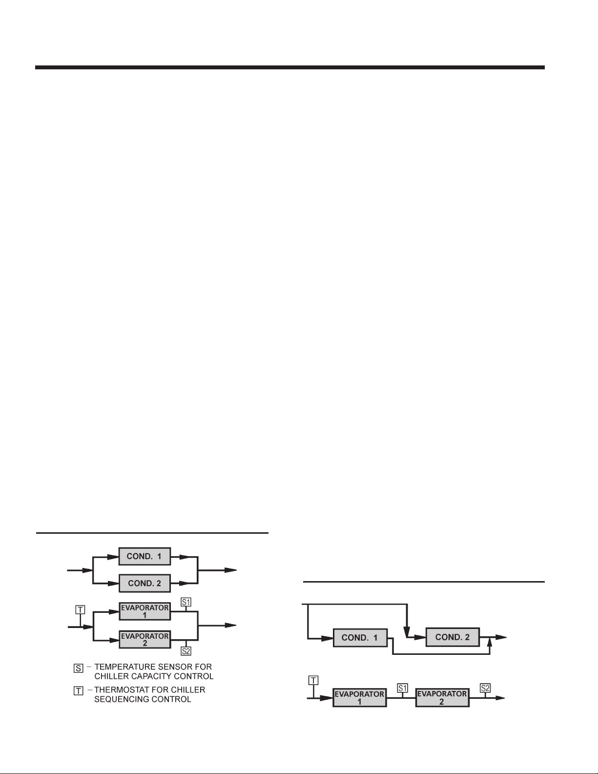
Parallel Arrangement (Refer to Fig. 1) – Chillers may
be applied in multiples with chilled and condenser water
circuits connected in parallel between the units. Fig. 1 represents a parallel arrangement with two chillers. Parallel
chiller arrangements may consist of equally or unequally
sized units. When multiple units are in operation, they
will load and unload at equal percentages of design full
load for the chiller.
Depending on the number of units and operating characteristics of the units, loading and unloading schemes
should be designed to optimize the overall efciency of
the chiller plant. It is recommended to use an evapora-
tor by-pass piping arrangement to bypass uid around
evaporator of any unit which has cycled off at reduced load
conditions. It is also recommended to alternate the chiller
cycling order to equalize chiller starts and run hours.
Series Arrangement (Refer to Fig. 2) – The chillers may
be applied in pairs with chilled water circuits connected in
series and condenser water circuits connected in parallel.
All of the chilled water ows through both evaporators
with each unit handling approximately one-half of the
total load. When the load decreases to a customer selected load value, one of the units will be shut down by a
sequence control. Since all water is owing through the
operating unit, that unit will cool the water to the desired
temperature.
storage control mode described on page 6.
Particular attention must be paid to the application of
two or more chillers with evaporators in parallel or series
when the brine temperature is below 32°F (0°C). The
brine MUST NOT ow through the evaporator of the
idle chiller, because it can cause the condenser water to
freeze. A bypass or other type of arrangement is required
that shuts off ow to the idle evaporator. When units are
applied in series with lead/lag capability, the units should
be identical.
REFRIGERANT RELIEF PIPING
Each chiller is equipped with pressure relief devices. The
purpose of the relief devices is to quickly relieve excess
pressure of the refrigerant charge to atmosphere, as a
safety precaution in the event of an emergency such as
a re. They are set to relieve at an internal pressure of
300 psig (2069 KPa) and are located on the condenser,
evaporator and oil separator; and are provided in accordance with ASHRAE 15 Safety Code and ASME or
applicable pressure vessel code. When required and designated on the order form, the relief devices will satisfy the
European requirements: (example VBG20). Under these
circumstances the relief devices may be relief valves,
overow valves or type tested Safety Pressure switches
or a combination of these devices.
BRINE APPLICATIONS
The YS Screw Chiller, utilizing the Frick Refrigeration compressor, is a good match for the high head requirements of
low temperature brine applications. This is particularly true
of thermal ice storage systems, typically requiring 22°F
(–5.6°C) to 24°F (–4.4°C) leaving brine temperatures.
This performance is enhanced with the standard thermal
In addition to the spring-loaded, re-seating-type relief
valves that are sized for pressure vessel volume, each unit
is equipped with a rupture disk. This rupture disk is able
to relieve the entire pumping capacity of the compressor
if electronic safeties fail, providing protection for property
and personnel. This device is set for 345 psig (2379 KPa)
[45 psig above the re-seating relief valves set at 300 psig
(2069 KPa)].
Sized to the requirements of applicable codes, a vent line
must run from the relief device to the outside of the building. This refrigerant relief piping must include a cleanable,
FIG. 1 – PARALLEL COOLERS
PARALLEL CONDENSERS
24 JOHNSON CONTROLS
FIG. 2 – SERIES COOLERS
PARALLEL CONDENSERS
Page 25

FORM 160.80-EG1 (808)
Sheet1
Freq Rated Voltage
Operating Voltage
Min. Max.
60Hz
200 200/208 180 220
230 220/240 208 254
380 380 342 415
416 416 375 457
460 440/460/480 414 508
575 575/600 520 635
2300 2300 2070 2530
3300 3300 2970 3630
4000 4000/4160 3600 4576
50Hz
346 346 311 381
380 380/400 342 423
415 415 374 440
3300 3300 2970 3630
Nameplate
Voltage
vertical-leg dirt trap to catch vent-stack condensation.
Vent piping must be arranged to avoid imposing a strain
on the relief connections and should include one exible
connection.
SOUND AND VIBRATION CONSIDERATIONS
A Millennium chiller is not a source of objectionable sound
and vibration in normal air conditioning applications.
Neoprene isolation mounts are furnished as standard
with each unit. Optional level-adjusting spring isolator assemblies designed for 1” static deection are available.
Millennium chiller sound pressure level ratings will be
furnished upon request.
Control of sound and vibration transmission must be taken
into account in the equipment room construction as well
as in the selection and installation of the equipment.
THERMAL INSULATION
No appreciable operating economy can be achieved by
thermally insulating the chiller. However, the chiller’s
cold surfaces should be insulated with a vapor barrier
insulation sufcient to prevent condensation. A chiller can
be factory insulated with 3/4” (19mm) or 1-1/2” (38mm)
thick insulation, as an option. This insulation will normally
prevent condensation in environments with dry bulb temperatures of 50°F to 90°F (10°C to 32°C) and relative
humidities up to 75% [3/4” (19mm) thickness] or 90% [1-
1/2” (38mm) thickness]. The insulation is painted and the
surface is exible and reasonably resistant to wear. It is
intended for a chiller installed indoors and, therefore, no
TABLE 2 – MOTOR VOLTAGE VARIATIONS
protective covering of the insulation is usually required.
If insulation is applied to the water boxes at the job site,
it must be removable to permit access to the tubes for
routine maintenance.
VENTILATION
The ASHRAE Standard 15 Safety Code for Mechanical
Refrigeration requires that all machinery rooms be vented
to the outdoors utilizing mechanical ventilation by one
or more power-driven fans. This standard, plus National
Fire Protection Association Standard 90A, state, local
and other related codes should be reviewed for specic
requirements. Since the Millennium chiller motor is aircooled, ventilation should allow for the removal of heat
from the motor.
In addition, the ASHRAE Standard 15 requires a refrigerant vapor detector to be employed for all refrigerants. It is
to be located in area where refrigerant from a leak would
be likely to concentrate. An alarm is to be activated and
the mechanical ventilation started at a value no greater
than the TLV (Threshold Limit Value) of the refrigerant.
ELECTRICAL CONSIDERATIONS
Motor Voltage – Low voltage motors (200 - 600 volts) are
furnished with six leads. Medium voltage (2300 - 4160
volts) motors have three leads. Motor circuit conductor
size must be in accordance with the National Electrical
Code (NEC), or other applicable codes, for the motor
full-load amperes (FLA). Flexible conduit should be used
for the last several feet to the chiller in order to provide
vibration isolation. Table 2 lists the allowable variation in
voltage supplied to the chiller motor. The unit nameplate
is stamped with the specic motor voltage and frequency
for the appropriate motor.
Starters – The chiller is available with a factory-mounted
and wired YORK Solid State Starter for 200 - 600 volt
applications. Other types of remote mounted starters are
available. These electro-mechanical starters must be
furnished in accordance with Johnson Controls Standard
R-1079 Specication. This will ensure that starter components, controls, circuits, and terminal markings will be
suitable for required overall system performance.
Controls – A 115 volt, single phase, 60 or 50 Hertz (4.5
kVa) power supply must be furnished to the chiller from a
separate, fused disconnect or from a control transformer
included as an option with electro-mechanical starters.
No eld control wiring is required, when the YORK SSS
is supplied.
Copper Conductors – Only copper conductors should be
connected to compressor motors and starters. Aluminum
conductors have proven to be unsatisfactory when connected to copper lugs. Aluminum oxide and the difference
25JOHNSON CONTROLS
Page 26

Application Data - continued
in thermal conductivity between copper and aluminum
cannot guarantee the required tight connection over a
long period of time.
Power Factor Correction Capacitors – Capacitors can
be applied to a chiller for the purpose of power factor correction. For remote-Mounted Electro-Mechanical Starters,
the capacitors should be located on the load side of the
starter. For YORK SSS, the capacitors must be located on
the line side of the starter. The capacitors must be sized
and installed to meet the National Electrical Code (NEC)
and be veried by JOHNSON CONTROLS.
Ampacity on Load Side of Starter – Electrical power
wire size to the chiller is based on the minimum unit ampacity. For YORK SSS, this wiring is done at the factory.
For remote starters, the National Electrical Code denes
the calculation of ampacity, as summarized below. More
specic information on actual amperage ratings will be
supplied with the submittal drawings.
• Six-lead type of starting (Star-Delta)
Minimum circuit ampacity per conductor (1 of 6):
Ampacity = .721 x compressor motor amps.
• Three-lead type of starting
(Across-the-Line, Autotransformer and
Primary Reactor)
125% of compr. + FLA of all other
Min. Circuit Ampacity =
Branch Circuit Overcurrent Protection – The branch
circuit overcurrent protection device(s) should be a
time-delay type, with a minimum rating equal to the next
standard fuse/breaker rating above the calculated value.
It is calculated taking into account the compressor motor
amps and may also include control transformer. Refer to
submittal drawings for the specic calculations for each
application.
MOTOR ELECTRICAL DATA
The smallest motor available which equals or exceeds
the Input power (kW) from the chiller rating program is
selected from Tables 3 and 4. The full load amperes (FLA)
listed in the tables are maximum values and correspond
to the maximum motor kW listed. When the Input power
(kW) is less than maximum motor kW, the FLA should be
reduced using the following equation:
FLA = Motor kW x Max. Motor FLA
Max. Motor kW
The benet from the FLA correction is the possible use of
smaller power wiring and/or starter size.
motor amps loads on the circuit
Minimum circuit ampacity per conductor (1 of 3):
Ampacity = 1.25 x compressor motor amps.
Ampacity on Line Side of Starter –
The only additional load on the circuit for the chiller would
be the control transformer, unless it is supplied by a
separate source.
The locked rotor amperes (LRA) are read directly from
Tables 3 and 4 for specic Motor Code and voltage. This
is because the LRA is dependent only on motor size and
voltage and is independent of input power (kW).
Inrush amperes (IRA) depend on LRA and the type of
starter applied. The inrush can be calculated using a
percentage of LRA shown in Table 5.
26 JOHNSON CONTROLS
Page 27
TABLE 3 – 60 HZ ELECTRICAL DATA
Sheet1
MOTOR CODE CF CG CH CJ CK CL CM CN CP CR CS CT CU CV CW CX CY CZ
KW (MAX.) 125 144 161 190 214 240 257 276 302 333 368 395 435 478 514 542 578 617
SHAFT HP 154 177 201 237 270 302 327 351 385 424 468 503 554 608 655 690 740 790
FL EFF. – % 92
92 93 93 94 94 95 95 95 95 95 95 95 95 95 95 95.5 95.5
FL PF 0.9
0.9 0.9 0.9 0.9 0.9 0.9 0.9 0.9 0.9 0.9 0.9 0.9 0.9 0.9 0.9 0.9 0.9
VOLTS
208
FLA
389 447 507 594 680 757 799 886 975 1043 1162 — — — — — — —
LRA
2702 3235 3235 3962 4732 5096 5689 6011 6011 7644 8106 — — — — — — —
230
FLA
352 404 464 540 610 685 749 804 882 944 1050 1130 1250 — — — — —
LRA
2598 2598 2865 3460 3788 4260 4755 5162 5780 5780 6900 7400 7724 — — — — —
240
FLA
337 387 445 518 585 656 718 771 845 905 1006 1083 1198 — — — — —
LRA
2711 2711 3120 3610 3953 4445 4962 5386 6031 6031 7200 7722 8060 — — — — —
380
FLA
217 249 285 336 378 421 453 487 534 571 636 684 756 817 879 942 997 1065
LRA
1385 1385 1730 2153 2500 2577 2955 3254 3637 3810 4179 4480 4671 5326 5780 6782 5780 6644
416
FLA
199 228 260 307 346 385 412 445 488 522 581 625 691 747 810 860 911 973
LRA
1385 1385 1638 1967 2190 2356 2700 2976 3536 3637 3810 3810 4270 4869 5640 5780 5694 6069
440
FLA
184 211 238 281 319 358 392 397 461 493 549 591 646 706 759 813 861 920
LRA
1177 1301 1320 1655 1865 2037 2485 2485 2976 2976 3300 3644 3644 4209 4783 5357 4783 5249
460
FLA
176 202 228 269 305 342 375 380 441 472 525 565 618 675 726 778 824 880
LRA
1230 1360 1380 1730 1950 2130 2598 2598 3111 3111 3450 3810 3810 4400 5000 5600 5000 5488
480
FLA
169 194 219 258 292 328 359 364 423 452 503 541 592 647 696 746 790 843
LRA
1283 1419 1440 1805 2035 2223 2711 2711 3246 3246 3600 3976 3976 4591 5217 5843 5217 5727
575
FLA
141 162 185 216 250 274 300 318 353 377 420 452 500 540 581 622 659 704
LRA
909 909 1100 1384 1556 1700 1900 2066 2078 2413 2760 2960 3089 3550 4039 4440 4300 4200
600
FLA
135 155 177 207 240 263 288 305 338 361 403 433 479 518 557 596 632 675
LRA
949 949 1148 1444 1624 1774 1983 2156 2168 2518 2880 3089 3223 3704 4215 4633 4484 4383
2300
FLA
36 41 46 54 61 68 74 79 87 95 105 113 124 135 146 154 165 176
LRA
240 267 298 340 397 435 480 520 530 570 669 719 791 867 935 960 1008 1100
3300
FLA
25 29 32 38 43 48 52 55 61 66 73 79 86 94 102 108 115 123
LRA
160 175 210 240 280 310 310 343 382 383 466 501 551 576 652 682 719 744
4000
FLA
21 24 27 31 36 40 43 46 50 54 60 65 71 78 84 89 95 101
LRA
135 154 166 195 230 240 260 283 315 315 384 413 455 499 538 540 554 631
4160
FLA
20 23 26 30 34 38 41 44 48 52 58 63 68 75 81 85 91 97
LRA
140 160 173 203 239 250 270 294 328 328 399 430 473 519 560 562 576 656
Sheet1
TYPE STARTER STAR DELTA AUTO TRANSFORMER ACROSS THE LINE PRIMARY REACTOR
VOLTAGE LOW LOW LOW LOW LOW/HIGH LOW/HIGH LOW/HIGH HIGH HIGH
60HZ 200-600 200-600 200-600 200-600 200-4160 200-4160 200-4160 2300-4160 2300-4160
50 HZ 380-415 346-415 346-415 346-415 346-3300 346-3300 346-3300 2300-3300 2300-3300
NONE — 45 CLOSED — 33 OPEN — 33 CLOSED 80 64 — — 100 CLOSED 65 65 CLOSED 80 80
SOLID STATE
STARTER
TRANSITION % TAP
INRUSH AS A % OF
LRA
CLOSED 57.7
33
CLOSED 65
42.3
FORM 160.80-EG1 (808)
NOTE: FLA = Full Load Amps; LRA = Locked Rotor Amps
TABLE 4 – MOTOR STARTERS
27JOHNSON CONTROLS
Page 28
Application Data - continued
TABLE 5 – 50 HZ ELECTRICAL DATA
Motor
CodE
shaFt hP
FL EFF. – %
FL PF
VoLts aMPErEs (MaX)
346
380
400
415
3300
NOTE: 1. Chiller performance for 50 Hertz applications is outside the scope of the ARI Certication Program.
2. FLA = Full Load Amps; LRA = Locked Rotor Amps
5CC 5Cd 5CE 5CF 5CG 5Ch 5CI 5CJ 5CK 5CL 5CM 5Cn 5Co 5CP 5CQ 5Cr 5Cs
121 136 160 180 201 215 231 254 280 309 332 366 402 432 455 481 518
148 168 198 225 252 272 292 321 353 390 419 462 507 546 575 608 658
91.1 92.4 92.4 93.4 93.4 94.2 94.2 94.2 94.2 94.2 94.2 94.2 94.2 94.2 94.2 94.2 94.7
0.86 0.86 0.86 0.86 0.86 0.86 0.87 0.87 0.87 0.87 0.87 0.87 0.87 0.87 0.87 0.87 0.88
224 258 302 340 380 417 437 481 528 584 630 692 578 816 860 909 982
FLa
1385 1721 1790 2208 2467 2598 2840 3081 3350 3706 3810 4177 4830 4944 5373 5780 5780
Lra
204 235 275 309 346 379 398 438 481 532 572 630 690 743 783 841 895
FLa
1385 1385 1640 1890 2144 2464 2590 2806 3050 3375 3700 3810 4400 4500 4892 5600 5491
Lra
194 223 261 294 329 360 378 416 457 505 543 599 656 706 744 799 850
FLa
1458 1458 1726 1990 2257 2594 2726 2954 3211 3553 3895 4011 4632 4737 5150 5895 5780
Lra
187 215 252 284 317 347 364 401 441 487 526 577 632 680 717 764 819
FLa
1283 1385 1490 1700 2031 2175 2366 2569 2794 3088 3402 3478 3810 4117 4480 5130 5108
Lra
FLa
Lra
24 27 32 36 41 44 47 50 56 62 66 73 80 87 91 96 103
159 162 209 236 241 274 294 318 317 388 423 455 499 516 572 614 644
TABLE 6 – AVAILABLE COMPRESSOR/SHELL/MOTOR COMBINATIONS (R-22 & R-134a)
CoMPrEssor
CodE
s0
s1
s2
s3
s4
s5
CooLEr
shELL
BA, BB BA, BB, CA, CB
CA, CB BA, BB, CA, CB
BA, BB BA, BB, CA, CB
CA, CB BA, BB, CA, CB CJ, CK
CA, CB CA, CB, DA, DB
DA, DB, DC CA, CB, DA, DB 5 CG, 5 CH
DA, DB, DC CA, CB, DA, DB
EA, EB, EC
FA, FB, FC
FA, FB, FC FA, FB
CondEnsEr
shELL
EA, EB, FA, FB
FA, FB
r-22, 60 hZ r-134a, 60 hZ r-22, 50 hZ
CF, CG, CH CF, CG, CH 5 CC, 5 CD
CF, CG, CH,
CJ, CK
CG, CH, CJ,
CK, CL, CM
CJ, CK, CL, CM,
CN, CP, CR
CK, CL, CM, CJ, CK, CL, CM, CN, CP, 5 CF, 5 CG,
CN, CP, CR, CR, CS, CT, CU, CV 5 CH, 5 CI,
CS, CT, CU,
CV
Motor CodE
CF, CG, CH,
CF, CG, CH, CJ
CK, CL, CM
CG, CH, CJ, CK
CL, CM, CN, CP, CR
CK, CL, CM, CN, CP, CR
CS, CT, CU, CV
5 CC, 5 CD, 5 CE,
5 CF
5 CD, 5 CE, 5 CF,
5 CF, 5 CG, 5 CH,
5 CI, 5 CJ, 5 CK
5 CJ, 5 CK,
5 CL, 5 CM,
5 CN, 5 CO
28 JOHNSON CONTROLS
Page 29
TABLE 7 – AVAILABLE COMPRESSOR/SHELL/MOTOR COMBINATIONS (50 HZ, R-134a ONLY)
FORM 160.80-EG1 (808)
CoMPrEssor
CodE
s0
s1
s2
s3
s4
s5
CooLEr
shELL
BA, BB BA, BB, CA, CB 5 CC, 5 CD
CA, CB BA, BB, CA, CB
BA, BB BA, BB, CA, CB 5 CC, 5 CD,
CA, CB BA, BB, CA, CB 5 CE, 5 CF
BA, BB BA, BB, CA, CB 5 CC, 5 CD,
CA, CB BA, BB, CA, CB, DA, DB 5 CE, 5 CF,
DA, DB, DC CA, CB, DA, DB 5 CG, 5 CH
CA, CB CA, CB, DA, DB 5 CC, 5 CD, 5 CE, 5 CF,
DA, DB, DC CA, CB, DA, DB 5 CG, 5 CH, 5 CI, 5 CJ, 5 CK
DA, DB, DC CA, CB, DA, DB 5 CE, 5 CF, 5 CG, 5 CH,
EA, EB, EC EA, EB, FA, FB 5 CI, 5 CJ, 5 CK, 5 CL,
FA, FB, FC EA, EB, FA, FB 5 CM, 5 CN, 5 CO
EA, EB, EC EA, EB, FA, FB 5 CF, 5 CG, 5 CH, 5 CI,
FA, FB, FC EA, EB, FA, FB
CondEnsEr
shELL
Motor CodE
5 CJ, 5 CK, 5 CL,
5 CM, 5 CN, 5 CO
29JOHNSON CONTROLS
Page 30
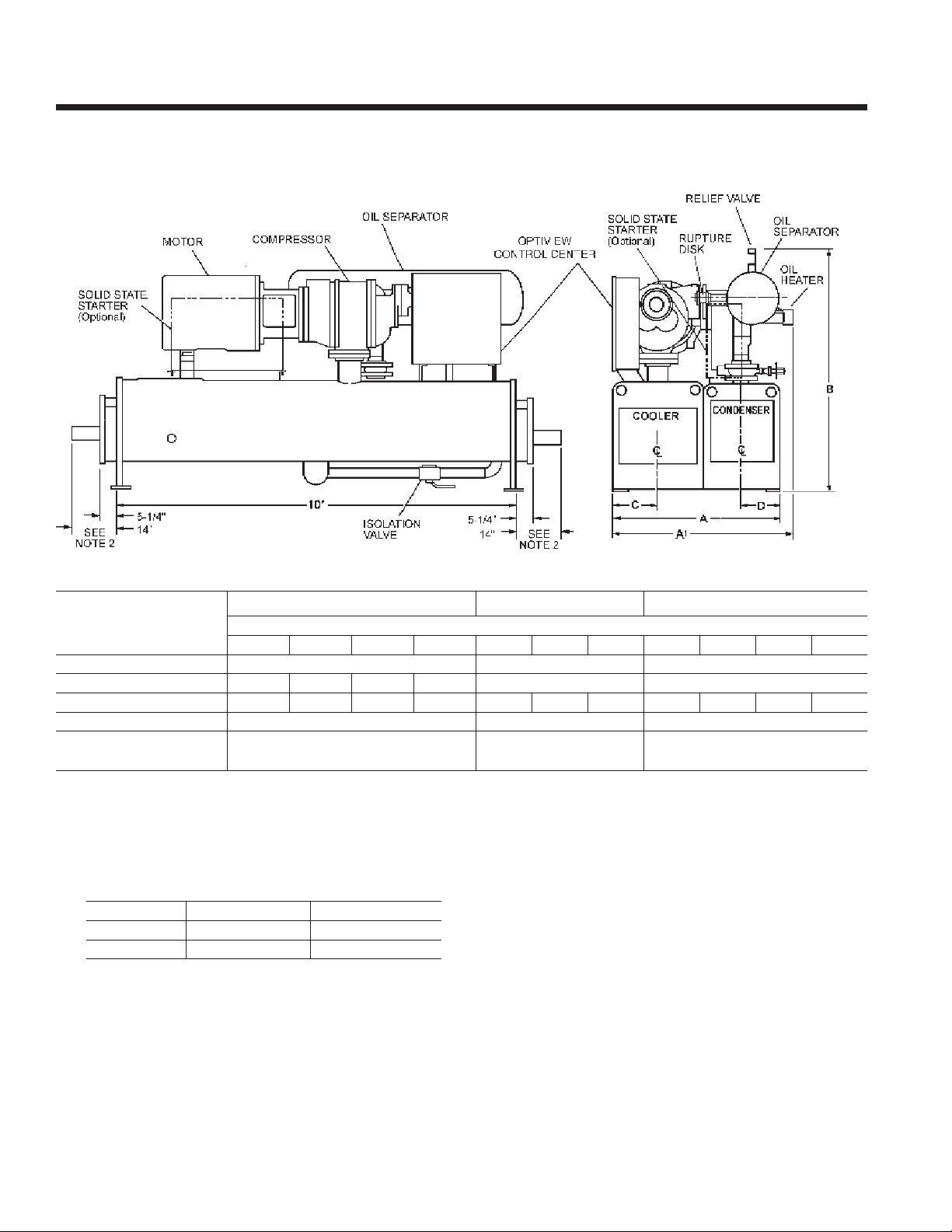
Dimensions – Std
S0 - S3 COMPRESSOR
R-22 & R-134a UNITS
(50 and 60 Hz)
s0 and s1 CoMPrEssor s2 CoMPrEssor s2 and s3 CoMPrEssor
dIMEnsIon
B-B B-C C-B C-C B-B B-C C-B C-C C-d d-C d-d
a
1
a
B – oVEraLL hEIGht
C – CooLEr C/L
d – CondEnsEr C/L
Refer to Tables 6 and 7 on pages 26 & 27 for valid compressor/shell/motor combinations.
4’–6-3/4” 4’–6-1/4” 4’-6-3/4” 4’–6-1/4” 5’–3-3/4” 5’–3-3/4”
3
5’–8-5/8” 5’–11-1/2” 5’–10-1/4” 5’–11-1/2” 5’–11-1/4” 6’–3-1/4” 6’–3-1/4” 6’–3-1/4” 6’–7-5/8” 6’–8-3/4” 6’–9-3/8”
4’–2-7/8” 5’–2-1/2” 5’–2-1/2”
1’–1-7/8” 1’–5” 1’–5”
0’–11-5/8” 1’–2-1/4” 1’–2-1/4”
shELL CodEs (EVaPorator – CondEnsEr)
REFRIGERANT RELIEF VALVE CONNECTIONS
shELL CodE EVaPorator sIZE CondEnsEr sIZE
B, C
d
NOTES:
1. All dimensions are approximate. Certied dimensions are available on request.
2. Determine overall unit length by adding water box dimension to tube sheet length:
5-1/4” for compact return box
14” for compact water box with ANSI/AWWA C-606 couplings water nozzles
Add 1/2” to each compact water box with optional anged water nozzles
3. Unit height includes steel mounting plates under tube sheets. To determine overall height, add 7/8” for neoprene isolators
(1” for optional spring isolators).
3/4” FPT SINGLE 3/4” FPT DUAL
1” FPT SINGLE 3/4” FPT DUAL
CoMPrEssor CodE oIL sEParator sIZE
S0, S1 2” RUPTURE DISK & 3/4” FPT SINGLE
S2, S3 2” RUPTURE DISK & 3/4” FPT DUAL
30 JOHNSON CONTROLS
Page 31

S4 - S5 COMPRESSOR
R-22 & R-134a UNITS
(50 and 60 Hz)
FORM 160.80-EG1 (808)
NOTES:
s4 CoMPrEssor s4 and s5 CoMPrEssor
dIMEnsIon
d-C d-d E-E E-F F-E F-F
a
1
a
2
a
B – oVEraLL hEIGht
C – CooLEr C/L
d – CondEnsEr C/L
Refer to Tables 6 and 7 on pages 26 & 27 for valid compressor/shell/motor combinations.
1. All dimensions are approximate. Certied dimensions are available on request.
2. Determine overall unit length by adding water box depth from table below to tube sheet length:
tYPE CoMPaCt WatEr BoX d E F d E F
3
EVaPorator
CondEnsEr
oIL sEParator
RETURN BOX
WITH VICTAULIC CONN.
WITH FLANGED CONN. 1’–2-3/8” 1’–2-3/8” 1’–3-5/8” 1’–2-3/8” 1’–2-3/8” 1’–3-5/8”
6’–2” 6’–2” 6’–2” 6’–4-1/2” 6’–6-1/2” 6’–9”
6’–9-7/8” 6’–9-7/8” 6’–9-7/8” 7’–0-3/8” 7’–3-5/8” 7’–2-5/8”
6’–3-3/8” 6’–3-3/8” — — — —
7’–9-1/8” 7’–9-1/8” 7’–9-1/8” 8’–2-1/4” 8’–2-1/4” 8’–2-1/4”
1’–7-3/4” 1’–7-3/4” 1’–7-3/4” 1’–7-3/4” 1’–10” 1’–10”
1’–5-1/4” 1’–5-1/4” 1’–5-1/4” 1’–6-1/2” 1’–5-1/4” 1’–6-1/2”
rEFrIGErant rELIEF VaLVE ConnECtIons
VEssEL
shELL CodEs (EVaPorator – CondEnsEr)
SIZE
1” FPT SINGLE
1” FPT DUAL
1” FPT DUAL & 2” NOM RUPTURE DISK
EVaPorator CodE CondEnsEr CodE
0’–5-1/2” 0’–5-1/2” 0’–7-3/4” 0’–5-1/4” 0’–5-1/4” 0’–7-5/8”
1’–1-7/8” 1’–1-7/8” 1’–3-1/8” 1’–1-7/8” 1’–1-7/8” 1’–3-1/8”
3. Unit height includes steel mounting plates under tube sheets. To determine overall installed height,
add 7/8” for neoprene isolators (1” for optional spring isolators).
31JOHNSON CONTROLS
Page 32
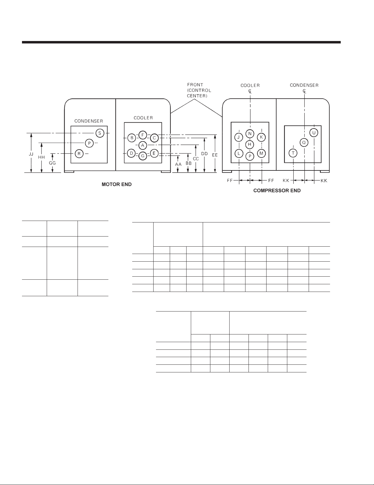
Dimensions - Std - continued
COMPACT WATER BOX NOZZLE ARRANGEMENTS
R-22 & R-134a UNITS
NOZZLE ARRANGEMENTS
no. oF
PassEs
1
2
3
CooLEr
In-out
A-H
H-A
E-B
D-C
M-J
L-K
P-F
G-N
Cond.
In-out
P-Q
Q-P
R-S
T-U
CooLEr
CodE
B
C
d
E
F
no. oF PassEs
1 2 3 aa BB CC dd EE FF
8 6 4 10 11 3/4 14-3/4 17-3/4 19-1/2 5
10 6 6 12 3/4 13 7/8 16 3/4 19 5/8 20 3/4 5 7/8
12 8 6 12 7/8 15 1/4 19 1/4 23 1/4 25 7/8 6 5/8
12 8 6 12 7/8 15 3/8 19 3/8 23 3/8 25 7/8 7 1/2
14 10 8 14-5/8 17 1/2 22 1/4 27 29 7/8 9 1/4
COOLER NOZZLE DIMENSIONS
noZZLE
sIZE (In.)
dIMEnsIons (In.)
CONDENSER NOZZLE DIMENSIONS
noZZLE
CondEnsEr
CodE
B
C
d, E
F
NOTES:
1. All dimensions are approximate (shown for 150 psig DWP water side). Certied dimensions are available on request.
2. Standard water nozzles are furnished as welding stub-outs with ANSI/AWWA C-606 grooves, allowing the option of welding, anges, or use of
ANSI/AWWA C-606 couplings couplings. Factory installed, class 150 (ANSI B16.5, round slip-on, forged carbon steel with 1/16” raised face), water
anged nozzles are optional. Companion anges, nuts, bolts and gaskets are not furnished.
3. Add 7/8” to all height dimensions to obtain installed height when using neoprene mounts or 1” for optional spring vibration isolator mounts.
4. One, two and three pass nozzle arrangements are available only in pairs shown and for all shell codes. Any pair of evaporator nozzles may be
used in combination with any pair of condenser nozzles.
5. Condenser water must enter the water box through the bottom connection for proper operation of the subcooler to achieve rated performance.
6. Cooler water must enter the water box through the bottom connection to achieve rated performance.
7. Connected piping should allow for removal of compact water box for tube access and cleaning.
sIZE (In.)
no. oF PassEs
1 2 GG hh JJ KK
8 6 13 16 3/4 20 1/4 4 1/2
10 8 11 1/2 16 3/4 22 1/8 4 3/8
12 10 14 1/4 20 25 7/8 6
14 12 17 24 1/2 32 7 3/4
dIMEnsIons (In.)
32 JOHNSON CONTROLS
Page 33
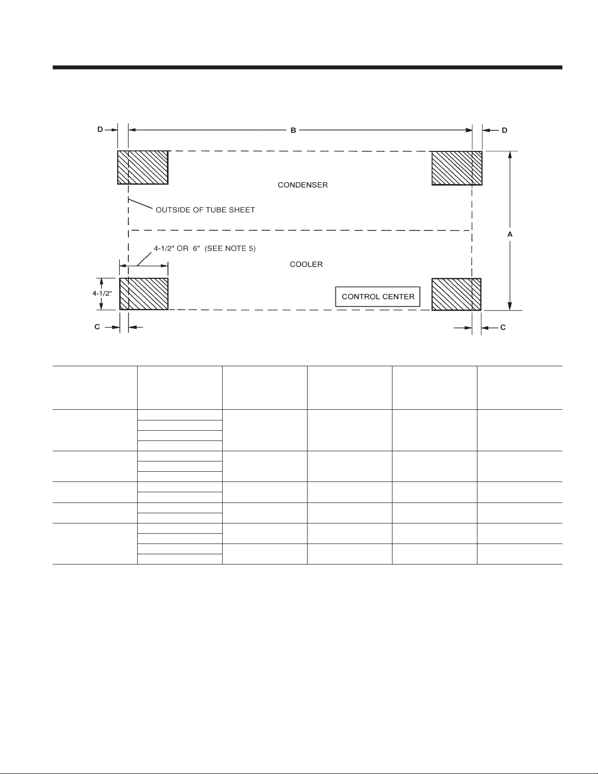
FLOOR LAYOUT – NEOPRENE ISOLATORS
R-22 & R-134a UNITS
FORM 160.80-EG1 (808)
shELL
CoMPrEssor
s0, s1
s2
s2, s3
s4
s4, s5
NOTES:
1. All dimensions are approximate. Certied dimensions are available on request.
2. Service clearance must be allowed as follows:
2’ at rear (condenser side) of unit and overhead.
3’ at front (evaporator/control center side) of unit.
10’ (12’ on S4/S5 compressor) on either end of unit for tube cleaning or replacement. A doorway or properly located opening may be used.
2’ on either end to allow for removal of water boxes for tube access and cleaning.
3. No special foundation required. Floor must be at and level within 1/4”, capable of carrying the operating weight of the unit.
4. Millennium unit has four steel plate foot supports located under the tube sheets at each corner of shell package. Neoprene isolator pads are
eld installed between foot support and oor.
5. All four neoprene isolator pads are identical. Pads are 1” thick with nominal 0.15” static deection. Unit operating weights under 16,365 Ibs.
use 4-1/2” x 4-1/2” isolators; weights above 16,365 Ibs use 4-1/2” x 6” isolators.
6. Loading per isolator pad equals operating weight divided by four.
CodEs
CooLEr-Cond.
B-B
B-C
C-B
C-C
B-B
C-B
C-C, C-D
D-C, D-D
D-C
D-D
E-E
E-F
F-E
F-F
a
tuBE shEEt
WIdth
4’–2-7/8” 10’ 1-7/8” 2-1/2”
5’–2-1/2” 10’ 1-7/8” 2-1/2”B-C
5’–2-1/2” 10’ 1-7/8” 2-1/2”
6’–2” 10’ 1-7/8” 2-1/2”
6’–2”
6’–4-1/2”
6’–6-1/2”
6’–9”
(to outsIdE oF tuBE
B
shELL LEnGth
shEEts)
12’ 1-7/8” 2-1/2”
12’ 1-7/8” 2-1/2”
C
EVaPorator
sIdE
d
CondEnsEr
sIdE
33JOHNSON CONTROLS
Page 34
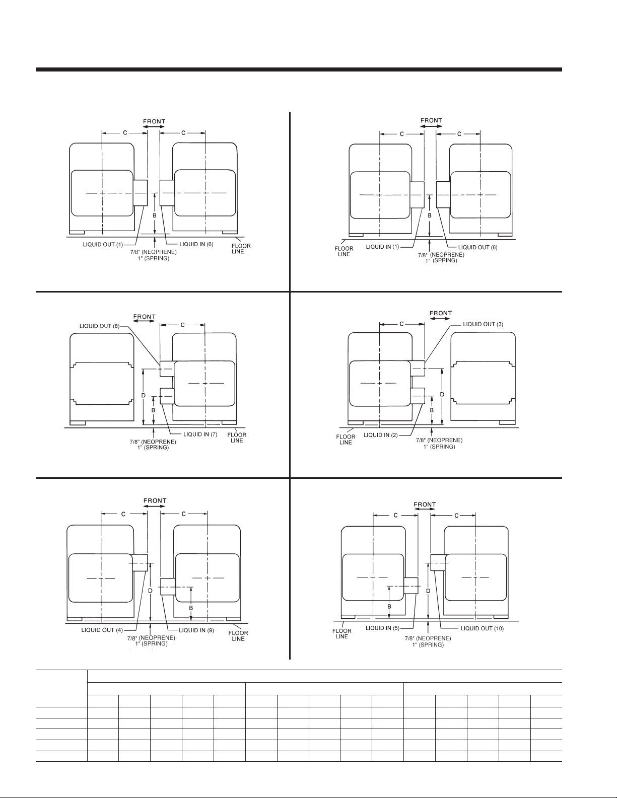
Dimensions – Std
EVAPORATOR NOZZLE ARRANGEMENTS – MARINE WATER BOXES
R-22 & R-134a UNITS
1-PASS
MOTOR END COMPR. END MOTOR END COMPR. END
2-PASS
1-PASS
2-PASS
MOTOR END MOTOR ENDCOMPR. END COMPR. END
3-PASS 3-PASS
MOTOR END MOTOR END
CooLEr
sIZE
B
C
d
E
F
a B C d E a B C d E a B C d E
15 1/2 15 1/4 19 — 7 3/4 13 1/2 9 1/2 19 21 6 3/4 13 1/2 11 19 19 1/2 6 3/4
17 1/2 16 3/4 20 3/4 — 8 3/4 13 1/2 11 1/4 20 3/4 22 1/4 6 3/4 13 1/2 13 1/4 20 3/4 22 7/8 6 3/4
20 19 1/4 23 3/4 — 10 15 1/2 14 1/2 23 3/4 29 1/2 7 3/4 15 1/2 13 3/4 23 3/4 25 1/4 7 3/4
20 19 3/8 24 5/8 — 10 16 15 1/8 24 5/8 29 1/8 8 16 13 7/8 24 3/8 25 3/8 8
21 22 3/8 28 1/4 — 10 1/2 19 16 1/4 28 1/4 33 9 1/2 17 15 1/4 28 1/4 29 1/4 8 1/2
1-Pass 2-Pass 3-Pass
COMPR. END COMPR. END
dIMEnsIons (In.)
34 JOHNSON CONTROLS
Page 35
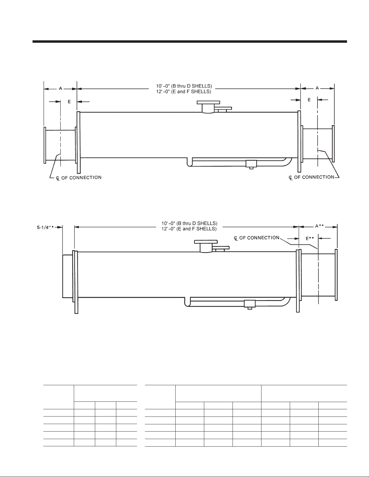
FORM 160.80-EG1 (808)
EVAPORATOR NOZZLE ARRANGEMENTS – MARINE WATER BOXES
R-22 & R-134a UNITS
MOTOR END
MOTOR END
COMPR. END
1-PASS & 3-PASS EVAPORATORS
COMPR. END
2-PASS EVAPORATORS
* Applies to compressor end if connections are on motor end.
** Applies to motor end if connections are on motor end.
EVAPORATORS NOZZLE SIZES
EVaPorator
CodE
B
C
d
E
F
noZZLE sIZE (In.)
no. oF PassEs
1 2 3
8 6 4
10 6 6
12 8 6
12 8 6
12 10 8
EVaPorator
CodE
B
C
d
E
F
WEIGHTS
(To be added to Standard Unit Weights on pages 36-37)
shIPPInG WEIGht
InCrEasE – LBs
1-Pass 2-Pass 3-Pass 1-Pass 2-Pass 3-Pass
554 295 562 788 391 755
810 417 668 1207 592 955
872 439 768 1316 600 1090
1040 607 996 1674 924 1535
1280 875 1130 1900 1025 1685
oPEratInG WEIGht
InCrEasE – LBs
35JOHNSON CONTROLS
Page 36
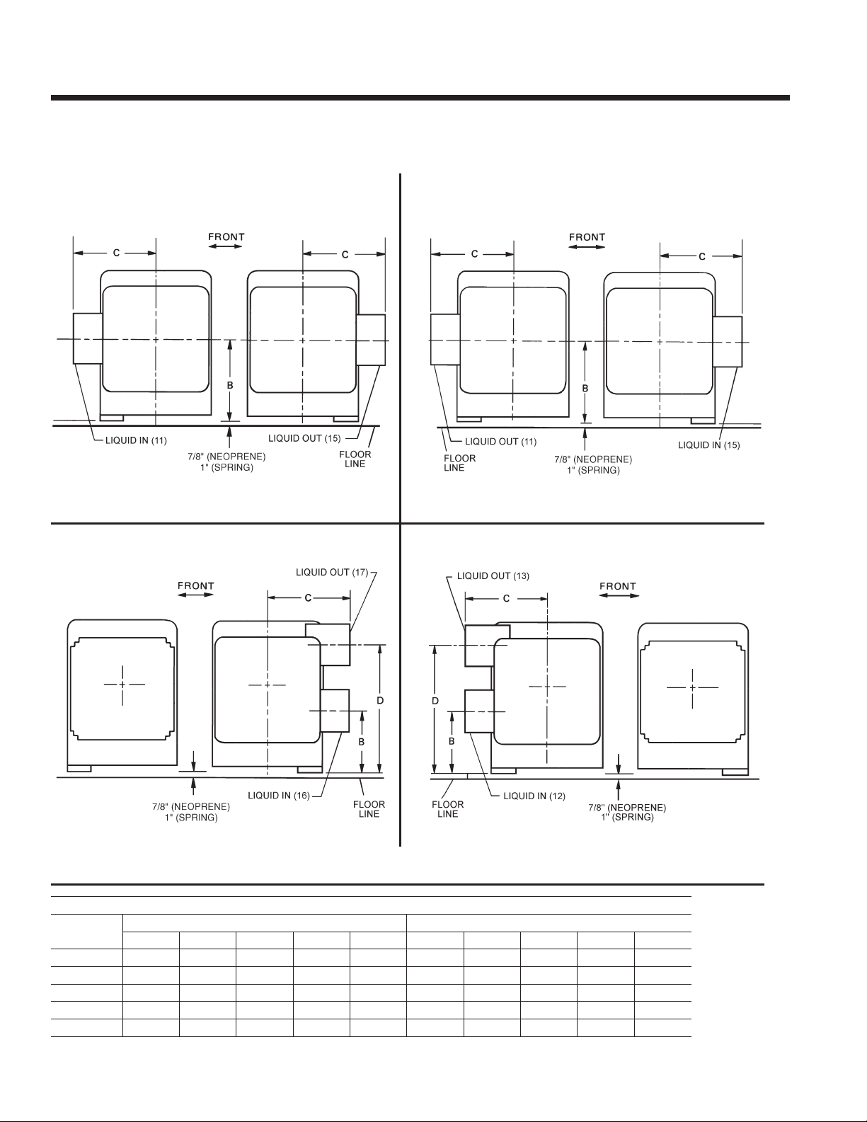
Dimensions – Std - continued
CONDENSER NOZZLE ARRANGEMENTS – MARINE WATER BOXES
R-22 & R-134a UNITS
1-PASS
2-PASS
1-PASS
MOTOR END MOTOR END
COMPR. END COMPR. END
2-PASS
CondEnsEr
sIZE
B
C
d
E
F
COMPR. END COMPR. END
dIMEnsIons (In.)
1-Pass 2-Pass
a B C d E a B C d E
15 1/2 16 7/8 17 5/8 — 7 3/4 13 1/2 11 1/8 17 5/8 22 5/8 6 3/4
17 1/2 16 3/4 18 1/2 — 8 3/4 15 1/2 12 18 1/2 26 7 3/4
20 20 21 1/8 — 10 17 1/2 15 21 1/8 31 3/4 8 3/4
20 20 21 1/8 — 10 17 1/2 15 21 1/8 31 3/4 8 3/4
21 24 1/2 25 1/8 — 10 1/2 21 18 1/2 25 1/8 38 1/4 10 1/2
MOTOR ENDMOTOR END
36 JOHNSON CONTROLS
Page 37
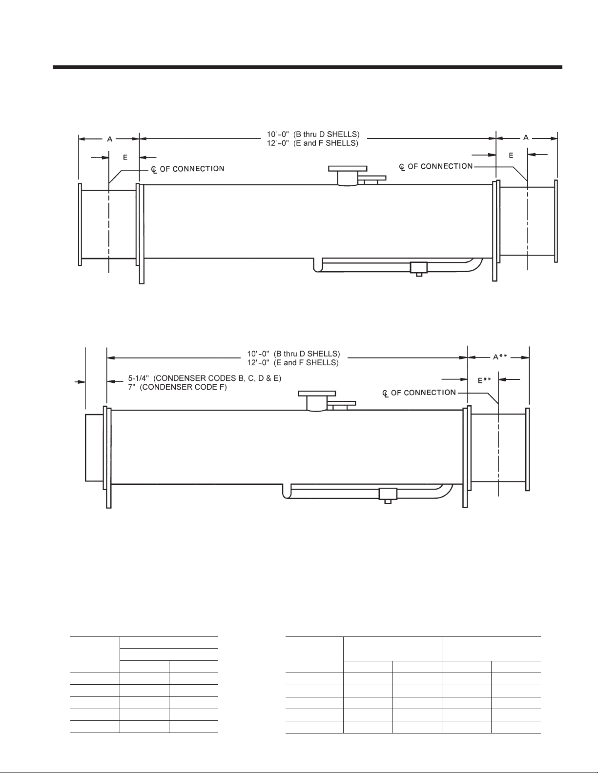
FORM 160.80-EG1 (808)
CONDENSER NOZZLE ARRANGEMENTS – MARINE WATER BOXES
R-22 & R-134a UNITS
MOTOR END
MOTOR END
1-PASS
COMPR. END
*
*
COMPR. END
2-PASS
* Applies to compressor end if connections are on motor end.
** Applies to motor end if connections are on motor end.
CONDENSER NOZZLE SIZES
CondEnsEr
CodE
B
C
d
E
F
noZZLE sIZE (In.)
no. oF PassEs
1 2
8 6
10 8
12 10
12 10
14 12
WEIGHTS
(To be added to Standard Unit Weights on pages 36-37)
CondEnsEr
CodE
B
C
d
E
F
shIPPInG WEIGht
InCrEasE – LBs
1-Pass 2-Pass 1-Pass 2-Pass
542 241 744 327
686 328 1018 475
818 317 1235 466
818 317 1235 466
1004 459 1586 704
oPEratInG WEIGht
InCrEasE – LBs
37JOHNSON CONTROLS
Page 38
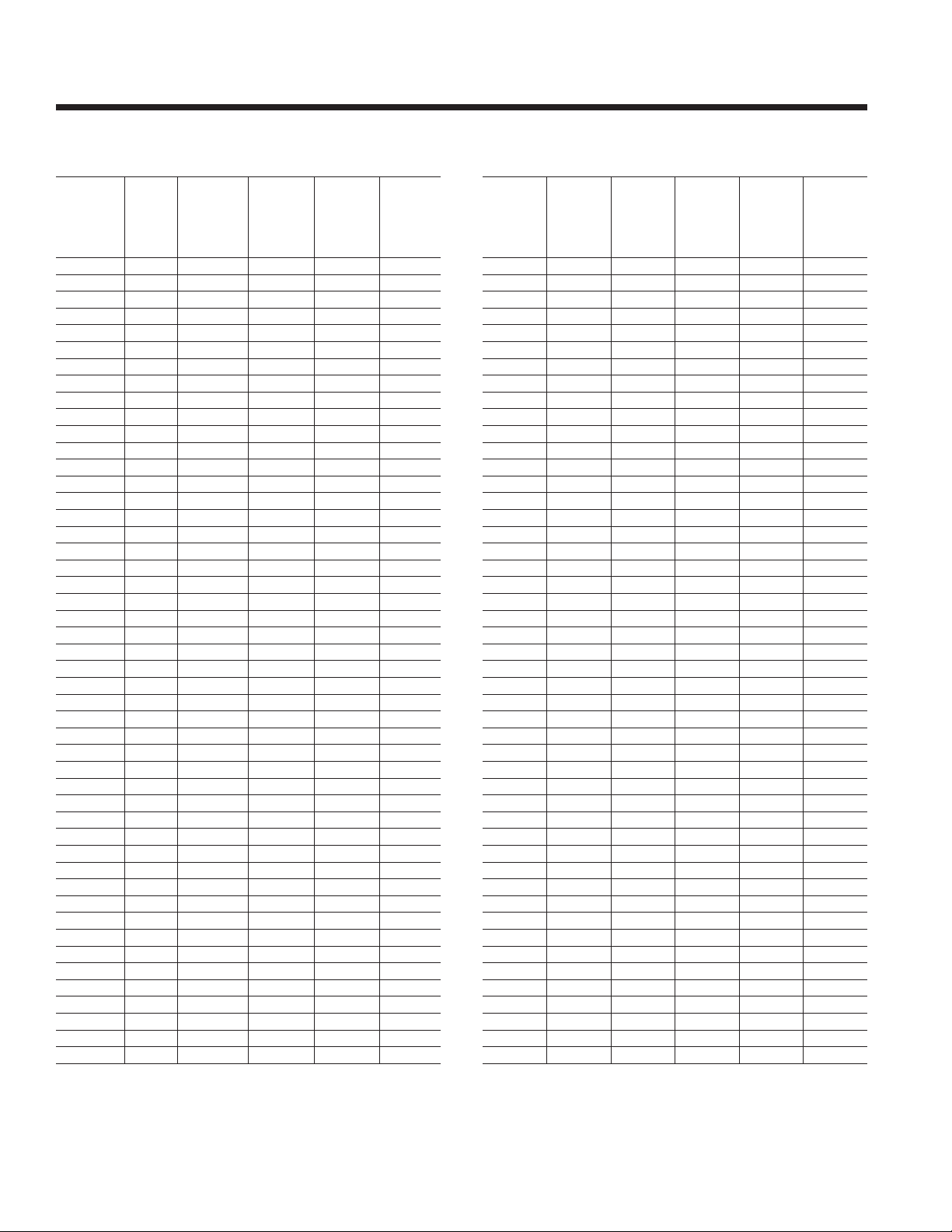
Weights – Std
R-22 & R-134a UNITS
shELL
CodE
EVaP.
– Cond.
Ba-Ba
Ba-BB
BB-Ba
BB-BB
Ba-Ca
Ba-CB
BB-Ca
BB-CB
Ca-Ba
Ca-BB
CB-Ba
CB-BB
Ca-Ca
Ca-CB
CB-Ca
CB-CB
Ba-Ba
Ba-BB
BB-Ba
BB-BB
Ba-Ca
Ba-CB
BB-Ca
BB-CB
Ca-Ba
Ca-BB
CB-Ba
CB-BB
Ca-Ca
Ca-CB
CB-Ca
CB-CB
Ba-Ba
Ba-BB
BB-Ba
BB-BB
Ba-Ca
Ba-CB
BB-Ca
BB-CB
Ca-Ba
Ca-BB
CB-Ba
CB-BB
Ca-Ca
Ca-CB
CB-Ca
CB-CB
CoM-
PrEs-
sor
S0 8,388 9,019 490 441
S0 8,538 9,235 490 441
S0 8494 9187 460 414
S0 8644 9403 460 414
S0 9,142 9,996 520 468
S0 9,416 10,388 520 468
S0 9,271 10186 480 432
S0 9,545 10,579 480 432
S0 9,297 10,084 620 558
S0 9,448 10,299 620 558
S0 9,528 10,412 620 558
S0 9,679 10,627 620 558
S0 10,011 11,020 650 585
S0 10,285 11,413 650 585
S0 10,242 11,348 650 585
S0 10,516 11,740 650 585
S1 8,454 9,085 490 441
S1 8,608 9,301 490 441
S1 8,560 9,253 460 414
S1 8,711 9,469 460 414
S1 9,208 9,974 520 468
S1 9,482 10,454 520 468
S1 9,337 10,252 480 432
S1 9,611 10,645 480 432
S1 9,363 10,150 620 558
S1 9,513 10,365 620 558
S1 9,594 10,478 620 558
S1 9,745 10,693 620 558
S1 10,077 11,086 650 585
S1 10,351 11,479 650 585
S1 10,308 11,414 650 585
S1 10,582 11,806 650 585
S2 10,542 11,174 — 441
S2 10,693 11,390 — 441
S2 10,648 11,342 — 414
S2 10,797 11,558 — 414
S2 11,298 12,065 — 468
S2 11,571 12,547 — 468
S2 11,426 12,342 — 432
S2 11,701 12,735 — 432
S2 11,452 12,241 — 558
S2 11,604 12,457 — 558
S2 11,683 12,567 — 558
S2 11,833 12,783 — 558
S2 12,146 13,155 680 612
S2 12,419 13,547 680 612
S2 12,377 13,483 680 612
S2 12,650 13,874 680 612
shIPPInG
Wt.
(LBs.)
oPEratInG
Wt.
(LBs.)
rEFrIG-
Erant
CharGE
(LBs.
r-22)
rEFrIG-
Erant
CharGE
(LBs.
r-134a)
shELL
CodE
EVaP.
– Cond.
Ca-da
Ca-dB
CB-da
CB-dB
da-Ca
da-CB
dB-Ca
dB-CB
dC-Ca
dC-CB
da-da
da-dB
dB-da
dB-dB
dC-da
dC-dB
Ca-Ca
Ca-CB
CB-Ca
CB-CB
Ca-da
Ca-dB
CB-da
CB-dB
da-Ca
da-CB
dB-Ca
dB-CB
dC-Ca
dC-CB
da-da
da-dB
dB-da
dB-dB
dC-da
dC-dB
da-Ca
da-CB
dB-Ca
dB-CB
dC-Ca
dC-CB
da-da
da-dB
dB-da
dB-dB
dC-da
dC-dB
CoM-
PrEs-
sor
S2 13,357 14,765 750 675
S2 13,874 15,506 750 675
S2 13,588 15,093 750 11/5/1901
S2 14105 15833 750 675
S2 13293 14480 840 756
S2 13,577 14872 840 756
S2 13,668 15008 840 756
S2 13941 15400 840 756
S2 14,026 15,552 840 756
S2 14,299 15,943 840 756
S2 14,549 16,124 950 855
S2 15,066 16,864 950 855
S2 14,869 16,608 910 819
S2 15,386 17,348 910 819
S2 15,215 17,437 840 756
S2 15,732 16,781 840 756
S3 12,360 13,372 — 612
S3 12,633 13,764 — 612
S3 12,591 13,698 — 612
S3 12,865 14,090 — 612
S3 13,574 14,983 — 675
S3 14,090 15,726 — 675
S3 13,804 15,313 — 675
S3 14,324 16,054 — 675
S3 13,497 14,673 840 756
S3 13,770 15,065 840 756
S3 13,861 15,201 840 756
S3 14,134 15,593 840 756
S3 14,219 15,744 840 756
S3 14,491 16,135 840 756
S3 14,741 16,316 950 855
S3 15,258 17,057 950 855
S3 15,061 16,800 910 819
S3 15,578 17,541 910 819
S3 15,408 17,333 840 756
S3 15,925 18,073 840 756
S4 17,068 18,247 — 740
S4 17,341 18,639 — 740
S4 17,431 18,776 — 740
S4 17,705 19,168 — 740
S4 17,791 19,320 — 740
S4 18,064 19,710 — 740
S4 18,313 19,893 — 830
S4 18,833 20,634 — 830
S4 18,635 20,378 — 800
S4 19,153 21,119 — 800
S4 18,983 20,912 — 740
S4 19,426 21,652 — 740
shIP-
PInG
Wt.
(LBs.)
oPEratInG
Wt.
(LBs.)
rEFrIG-
Erant
CharGE
(LBs.
r-22)
rEFrIG-
Erant
CharGE
(LBs.
r-134a)
38 JOHNSON CONTROLS
Page 39
R-22 & R-134a UNITS
50 AND 60 HZ
FORM 160.80-EG1 (808)
shELL
CodE
EVaP.
– Cond.
Ea-Ea
Ea-EB
EB-Ea
EB-EB
EC-Ea
EC-EB
Ea-Fa
Ea-FB
EB-Fa
EB-FB
EC-Fa
EC-FB
Fa-Ea
Fa-EB
FB-Ea
FB-EB
FC-Ea
FC-EB
Fa-Fa
Fa-FB
FB-Fa
FB-FB
FC-Fa
FC-FB
CoM-
PrEs-
sor
S4 20,460 21,890 1,400 1,260
S4 21,104 22,743 1,400 1,260
S4 20,955 22,484 1,350 1,215
S4 21533 23337 1,350 1,215
S4 21362 23139 1,300 1,170
S4 22,000 23991 1,300 1,170
S4 23,485 25592 1,520 1,368
S4 24695 27192 1,520 1,368
S4 23,914 26,180 1,520 1,368
S4 25,119 27,781 1,450 1,305
S4 24,382 26,840 1,450 1,305
S4 25,592 28,435 1,450 1,305
S4 22,922 24,998 — 1,690
S4 23,638 25,853 — 1,690
S4 23,711 25,902 — 1,690
S4 24,288 26,757 — 1,690
S4 24,171 27,076 — 1,620
S4 25,141 27,929 — 1,620
S4 25,977 28,655 2,000 1,800
S4 27,187 30,256 2,000 1,800
S4 26,626 29,552 2,000 1,800
S4 27,830 31,153 1,900 1,710
S4 27,148 30,730 1,900 1,710
S4 28,688 32,325 1,900 1,710
shIPPInG
Wt.
(LBs.)
oPEratInG
Wt.
(LBs.)
rEFrIG-
Erant
CharGE
(LBs.
r-22)
rEFrIG-
Erant
CharGE
(LBs.
r-134a)
shELL
CodE
EVaP
– Cond.
EA-EA S5 20,777 22,210 — 1,260
EA-EB S5 21,423 23,065 — 6/13/1903
EB-EA S5 21275 22807 — 1215
EB-EB S5 21853 23682 — 1215
EC-EA S5 21,681 23462 — 1,170
EC-EB S5 22,322 24317 — 1,170
EA-FA S5 23808 25919 — 1368
EA-FB S5 25,020 27,521 — 1,368
EB-FA S5 24,240 26,508 — 1,368
EB-FB S5 25,445 28,112 — 1,305
EC-FA S5 24,707 27,171 — 1,305
EC-FB S5 25,919 28,769 — 1,305
FA-EA S5 23,274 25,280 — 1,690
FA-EB S5 23,920 26,135 — 1,690
FB-EA S5 23,991 26,184 — 1,690
FB-EB S5 24,568 27,036 — 1,620
FC-EA S5 24,453 27,356 — 1,620
FC-EB S5 25,423 28,211 — 1,620
FA-FA S5 26,257 28,936 2,000 1,800
FA-FB S5 27,467 30,536 2,000 1,800
FB-FA S5 26,906 29,832 2,000 1,800
FB-FB S5 28,111 31,433 1,900 1,710
FC-FA S5 27,759 31,009 1,900 1,710
FC-FB S5 28,969 32,604 1,900 1,710
CoM-
PrEs-
sor
shIP-
PInG
Wt.
(LBs.)
oPEratInG
Wt.
(LBs.)
rEFrIG-
Erant
CharGE
(LBs.
r-22)
rEFrIG-
Erant
CharGE
(LBs.
r-134a)
NOTE: 1. Calculate total chiller weight by adding motor weight, solid state starter weight, and marine water box weights, if applicable.
2. Shipping weight includes refrigerant and oil charge. Operating weight includes water in tubes and water boxes.
3. Weights based on standard tubes in evaporators and condensers.
4. Operating weight based on R-22. Subtract difference in refrigerant charge if using R-134a.
MOTOR WEIGHTS
SOLID STATE STARTER
WEIGHT
Motor CodE WEIGht
60 hZ 50 hZ (LBs)
CF 5 CC 1,080
CG 5 CC 1,080
CH 5 CD 1,120
CJ 5 CE 1,120
CK 5 CF 1,460
CL 5 CG 1,520
CM 5 CH 1930
CN 5 CI 1930
CP 5 CJ 1,980
CR 5 CK 1,980
CS 5 CL 2370
CT 5 CM 2,480
CU 5 CN 2,480
CV 5 CO 2,635
sIZE LBs
7L, 14L 200
26L, 33L 300
39JOHNSON CONTROLS
Page 40
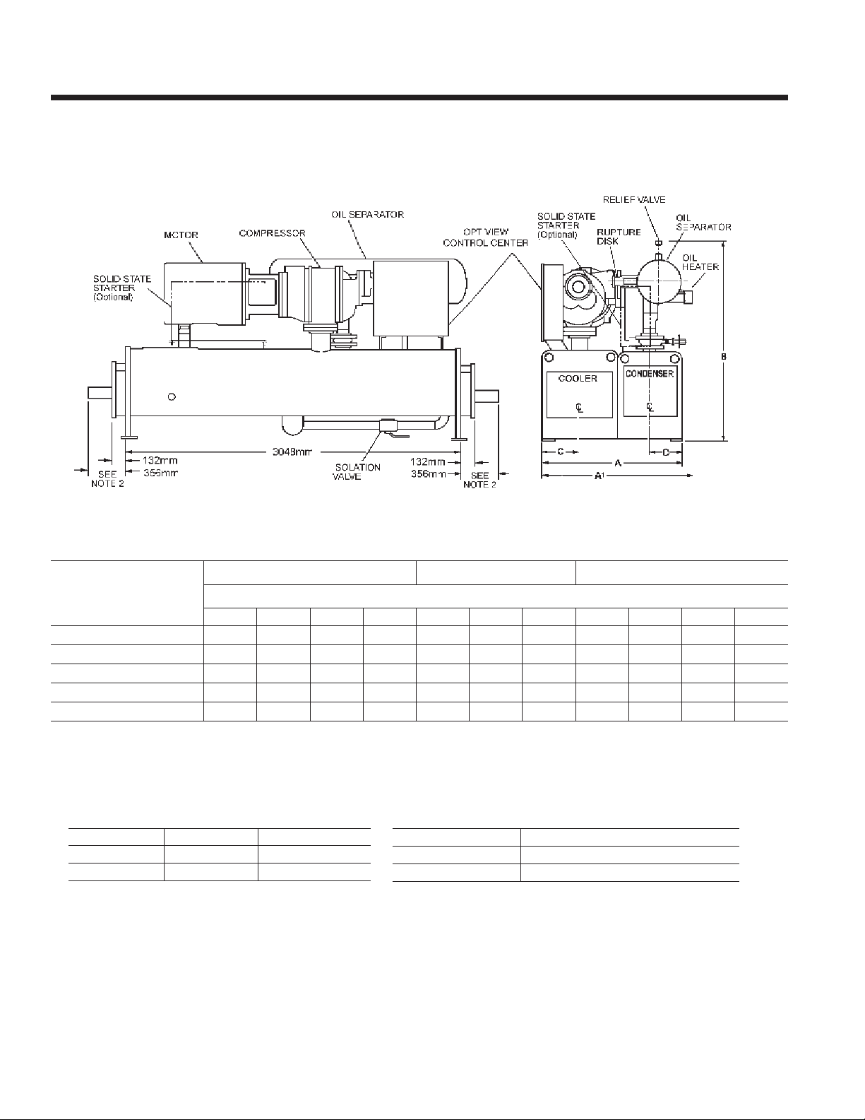
Dimensions – Metric
S0 - S3 COMPRESSOR
R-22 & R-134a UNITS
(50 and 60 Hz)
DIMENSIONS (mm)
s0 and s1 CoMPrEssor s2 CoMPrEssor s2 and s3 CoMPrEssor
shELL CodEs (CooLEr – CondEnsEr)
B-B B-C C-B C-C B-B B-C C-B C-C C-d d-C d-d
a – tuBE shEEt WIdth
a1 – oVEraLL WIdth
B – oVEraLL hEIGht
C – CooLEr C/L
d – CondEnsEr C/L
Refer to Tables 6 and 7 on pages 26 & 27 for valid compressor/shell/motor combinations.
3
1292 1292 1292 1292 1588 1588 1588 1588 1588 1588 1588
1349 1349 1349 1349 1591 1591 1591 1591 1591 1591 1591
1816 1895 1857 1899 1848 1946 1946 1946 2054 2102 2102
351 351 351 351 432 432 432 432 432 432 432
295 291 295 295 362 362 362 362 362 362 362
REFRIGERANT RELIEF VALVE CONNECTIONS
shELL CodE EVaP. sIZE CondEnsEr sIZE
B, C
d
NOTES:
1. All dimensions are approximate. Certied dimensions are available on request.
2. Determine overall unit length by adding water box dimension to tube sheet length:
132mm for compact return box
356mm for compact water box with ANSI/AWWA C-606 couplings water nozzles
Add 12.6mm to each compact water box with optional anged water nozzles
3. Unit height includes steel mounting plates under tube sheets. To determine overall installed height, add 22mm for neoprene isolators (25 mm
for optional spring isolators).
3/4” FPT SINGLE 3/4” FPT DUAL
1” FPT SINGLE 3/4” FPT DUAL
CoMPrEssor CodE oIL sEParator sIZE
s0, s1
s2, s3
2” RUPTURE DISK & 3/4” FPT SINGLE
2” RUPTURE DISK & 3/4” FPT DUAL
40 JOHNSON CONTROLS
Page 41

S4 - S5 COMPRESSOR
R-22 & R-134a UNITS
(50 and 60 Hz)
FORM 160.80-EG1 (808)
DIMENSIONS (mm)
s4 CoMPrEssor s4 and s5 CoMPrEssor
shELL CodEs (EVaPorator – CondEnsEr)
d-C d-d E-E E-F F-E F-F
a – tuBE shEEt WIdth
a1 – WIth soLId statE startEr
a2 – oVEraLL WIdth (LEss s.s.s)
B – oVEraLL hEIGht3
C – EVaPorator C/L
d – CondEnsEr C/L
Refer to Tables 6 and 7 on pages 26 & 27 for valid compressor/shell/motor combinations.
NOTES:
1. All dimensions are approximate. Certied dimensions are available on request.
2. Determine overall unit length by adding water box depth from table below to tube sheet length:
tYPE CoMPaCt WatEr BoX
rEturn BoX
WIth VICtauLIC ConnECtIon
WIth FLanGEd ConnECtIon
1,880 1,880 1,880 1,943 1,994 2,057
2,080 2,080 2,080 2,143 2,226 2,200
1,915 1,915 — — — —
2,365 2,365 2,365 2,496 2,496 2,496
502 502 502 502 559 559
438 438 438 470 438 470
rEFrIGErant rELIEF VaLVE ConnECtIons
VEssEL sIZE
EVaPorator
CondEnsEr
oIL sEParator
1” FPT DUAL & 2” NOM RUPTURE DISK
CooLEr CodE CondEnsEr CodE
d E F d E F
140 140 197 133 133 194
352 352 384 352 352 384
365 365 397 365 365 397
1” FPT SINGLE
1” FPT DUAL
3. Unit height includes steel mounting plates under tube sheets. To determine overall installed height,
add 22mm for neoprene isolators (25.4 for optional spring isolators).
41JOHNSON CONTROLS
Page 42

Dimensions – Metric - continued
COMPACT WATER BOX NOZZLE ARRANGEMENTS
R-22 and R-134a UNITS
NOZZLE ARRANGEMENTS
no. oF
PassEs
1
2
3
EVaPorator
In-out
A - H P - Q
H - A Q - P
E - B R - S
D - C T - U
M - J
L - K
P - F
G - N
Cond.
In-out
EVaP.
CodE
B
C
d
E
F
EVAPORATOR NOZZLE DIMENSIONS
noZZLE
sIZE (In.)
no. oF PassEs
1 2 3 aa BB CC dd EE FF
8 6 4 254 298 375 451 495 127
10 6 6 324 352 425 498 527 149
12 8 6 327 387 489 591 657 168
12 8 6 327 391 492 594 657 191
14 10 8 371 445 565 686 759 235
dIMEnsIons (MM)
CONDENSER NOZZLE DIMENSIONS
noZZLE
Cond.
CodE
B
C
d
E
F
NOTES:
1. All dimensions are approximate (shown for 1031 KPa DWP water side). Certied dimensions are available on request.
2. Standard water nozzles are furnished as welding stub-outs with ANSI/AWWA C-606 grooves, allowing the option of welding, anges, or use of
ANSI/AWWA C-606 couplings couplings. Factory installed, class 150 (ANSI B16.5, round slip-on, forged carbon steel with 1/16” raised face),
water anged nozzles are optional. Companion anges, nuts, bolts and gaskets are not furnished.
3. Add 22mm to all height dimensions to obtain installed height when using neoprene mounts or 25mm for optional spring vibration isolator
mounts.
4. One, two and three-pass nozzle arrangements are available only in pairs shown and for all shell codes. Any pair of evaporator nozzles may be
used in combination with any pair of condenser nozzles.
5. Condenser water must enter the water box through the bottom connection for proper operation of the subevaporator to achieve rated performance.
6. Cooler water must enter the water box through the bottom connection to achieve rated performance.
7. Connected piping should allow for removal of compact water box for tube access and cleaning.
sIZE (In.)
no. oF PassEs
1 2 GG hh JJ KK
8 6 330 425 514 114
10 8 292 425 562 111
12 10 368 514 660 152
12 10 375 521 667 152
14 12 432 622 813 197
dIMEnsIons (MM)
42 JOHNSON CONTROLS
Page 43
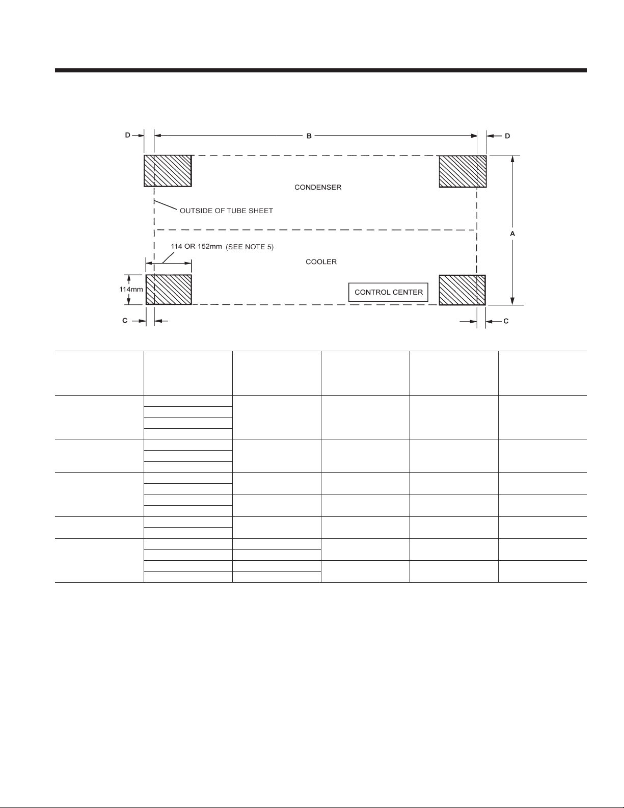
FLOOR LAYOUT – NEOPRENE ISOLATORS
R-22 & R-134a UNITS
FORM 160.80-EG1 (808)
shELL
CoMPrEssor
s0, s1
s2
s2, s3
s4
s4, s5
NOTES:
1. All dimensions are approximate. Certied dimensions are available on request.
2. Service clearance must be allowed as follows:
610mm at rear (condenser side) of unit and overhead.
915mm at front (evaporator/control center side) of unit.
3050mm (3660mm on S4/S5 compressor) on either end of unit for tube cleaning or replacement. A doorway or properly located
opening may be used.
610mm on either end to allow for removal of water boxes for tube access and cleaning.
3. No special foundation required. Floor must be at and level within 6mm, capable of carrying the operating weight of the unit.
4. Unit has four steel plate foot supports located under the tube sheets at each corner of shell package. Neoprene isolator pads are
eld installed between foot support and oor.
5. All four neoprene isolator pads are identical. Pads are 25mm thick. Unit operating weights under 7423 kg. use 114mm x 114mm isolators; weights
above 7423 kg. use 114mm x 152mm isolators.
6. Loading per isolator pad equals operating weight divided by four.
CodEs
EVaP. - Cond.
B-B
B-C
C-B
C-C
B-B
C-B
C-C
C-D
D-C
D-D
D-C
D-D
E-E 1880MM
E-F 1943MM
F-E 1994MM
F-F 2057MM
a
tuBE shEEt
WIdth
1292MM 3048MM 48MM 64MM
1588MM 3048MM 48MM 64MMB-C
1588MM 3048MM 48MM 64MM
1588MM 3048MM 48MM 64MM
1880MM 3048MM 48MM 64MM
(to outsIdE oF tuBE
B
shELL LEnGth
shEEts)
3658MM 48MM 64MM
3658MM 48MM 64MM
C
EVaP
sIdE
d
CondEnsEr
sIdE
43JOHNSON CONTROLS
Page 44
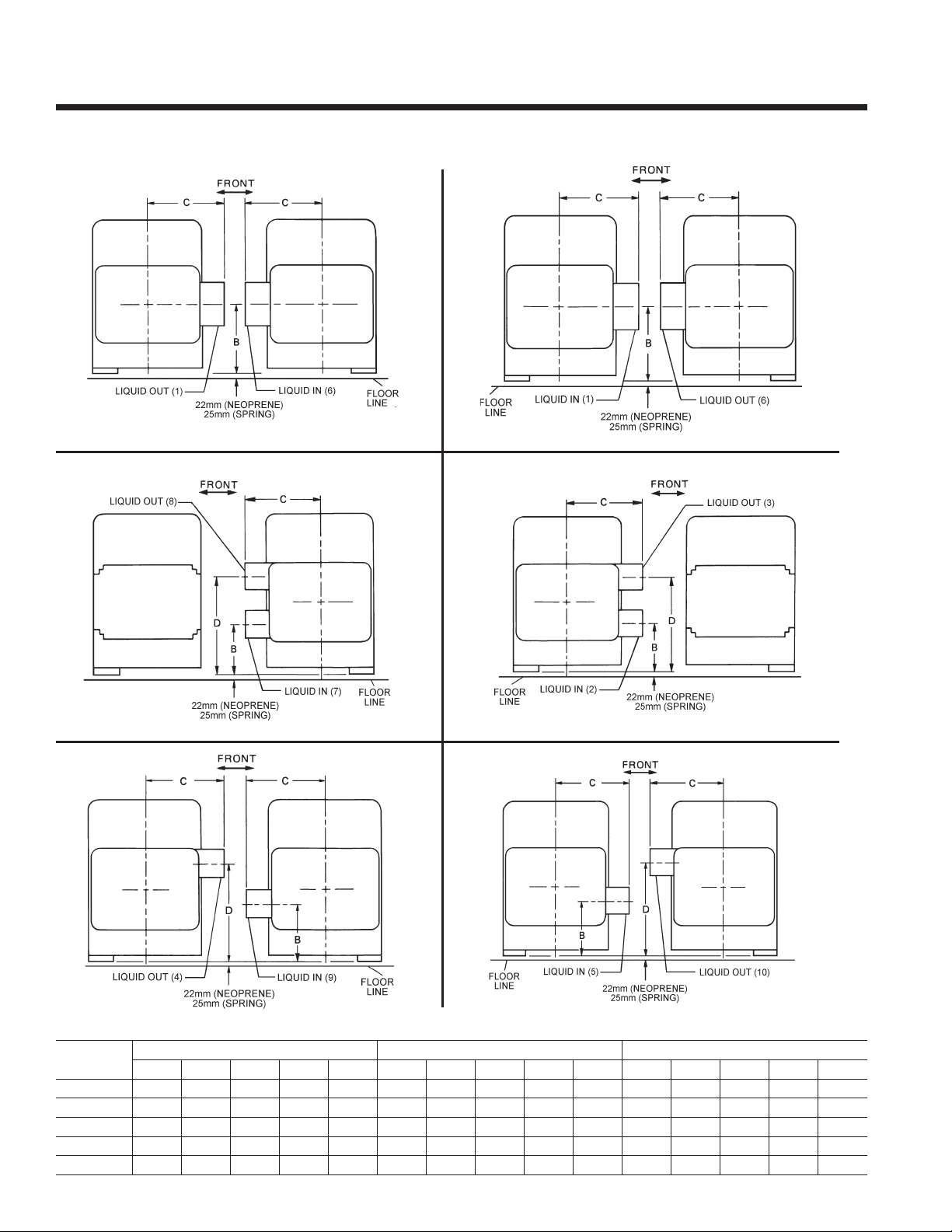
Dimensions – Metric - continued
COOLER NOZZLE ARRANGEMENTS – MARINE WATER BOXES
R-22 and R-134a UNITS
1-PASS 1-PASS
MOTOR END MOTOR END
COMPR. END COMPR. END
2-PASS 2-PASS
MOTOR END MOTOR END
COMPR. END COMPR. END
3-PASS 3-PASS
MOTOR END MOTOR END
CooLEr
sIZE
B
C
d
E
F
a B C d E a B C d E a B C d E
394 387 483 — 197 343 241 483 533 171 343 279 483 495 171
445 425 527 — 222 343 286 527 565 171 343 337 527 581 171
508 489 603 — 254 394 368 603 749 197 394 349 603 641 197
508 492 625 — 254 406 384 625 740 203 406 352 619 644 203
533 568 719 — 266 483 413 718 838 241 432 387 718 743 216
1-Pass 2-Pass 3-Pass
COMPR. END COMPR. END
DIMENSIONS (mm)
44 JOHNSON CONTROLS
Page 45
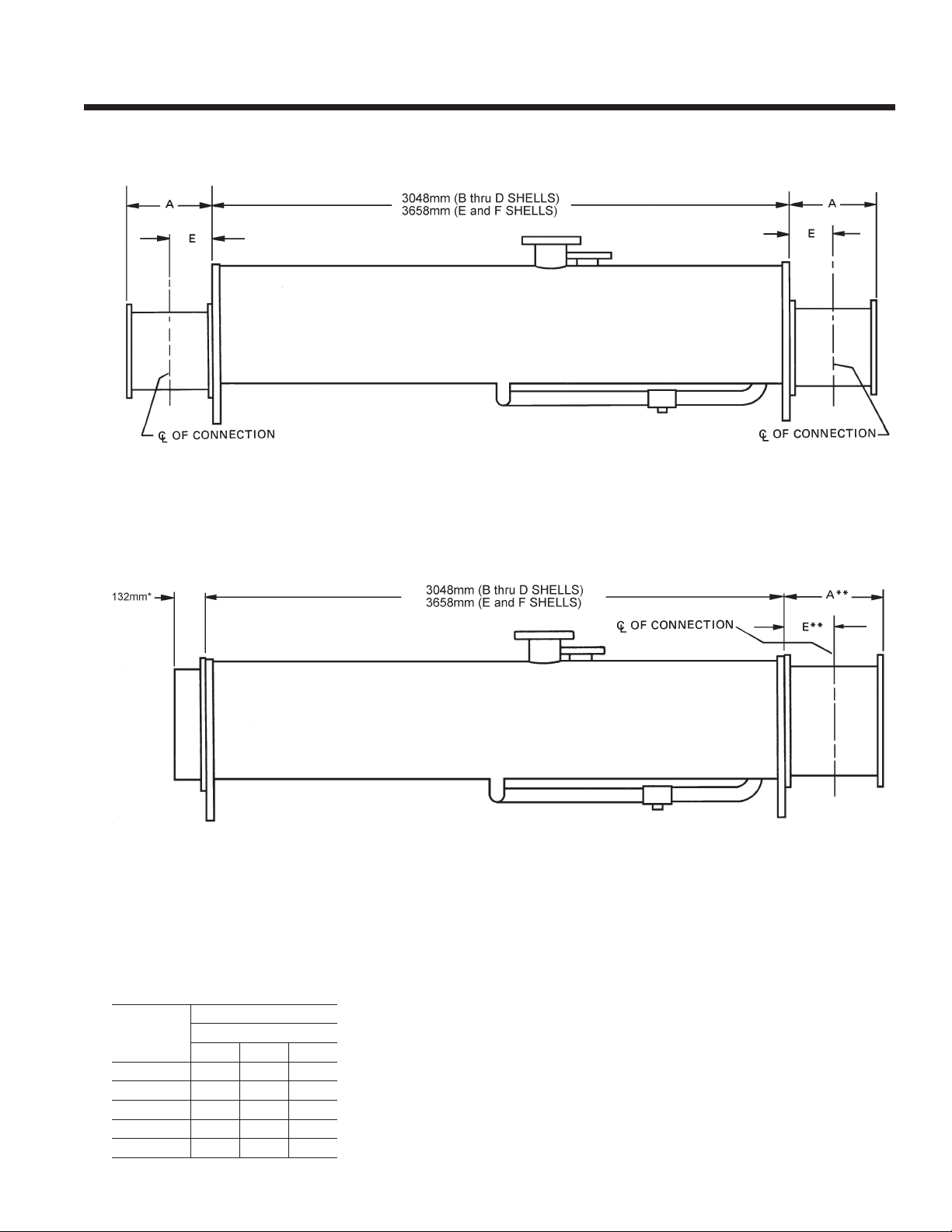
FORM 160.80-EG1 (808)
COOLER NOZZLE ARRANGEMENTS – MARINE WATER BOXES
R-22 & R-134a UNITS
MOTOR END
COMPR. END
1-PASS & 3-PASS COOLERS
COMPR. ENDMOTOR END
2-PASS COOLERS
* Applies to compressor end if connections are on motor end.
** Applies to motor end if connections are on motor end.
EVAP. NOZZLE SIZES
EVaPorator
CodE
B
C
d
E
F
noZZLE sIZE (In.)
no. oF PassEs
1 2 3
8 6 4
10 6 6
12 8 6
12 8 6
12 10 8
WEIGHTS (To be added to Metric Unit Weights on pages 46-47)
CooLEr
CodE
B
C
d
E
F
shIPPInG WEIGht
InCrEasE – KG
1-Pass 2-Pass 3-Pass 1-Pass 2-Pass 3-Pass
252 134 255 358 178 343
368 190 304 549 269 434
396 200 349 598 273 495
473 276 453 761 420 698
582 398 514 864 466 764
oPEratInG WEIGht
InCrEasE – KG
45JOHNSON CONTROLS
Page 46
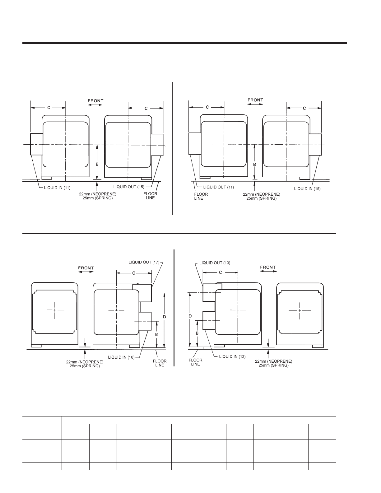
Dimensions – Metric - continued
CONDENSER NOZZLE ARRANGEMENTS – MARINE WATER BOXES
R-22 & R-134a UNITS
1-PASS 1-PASS
MOTOR END
COMPR. END COMPR. END
2-PASS
MOTOR END MOTOR END
COMPR. END
MOTOR END
2-PASS
COMPR. END
DIMENSIONS (mm)
CondEnsEr
sIZE
B
C
d
E
F
a B C d E a B C d E
394 429 448 — 197 343 283 448 575 171
445 425 470 — 222 394 305 470 660 197
508 508 537 — 254 445 381 537 806 222
508 508 537 — 254 445 381 537 806 222
533 622 638 — 267 533 470 638 972 267
1-Pass 2-Pass
46 JOHNSON CONTROLS
Page 47
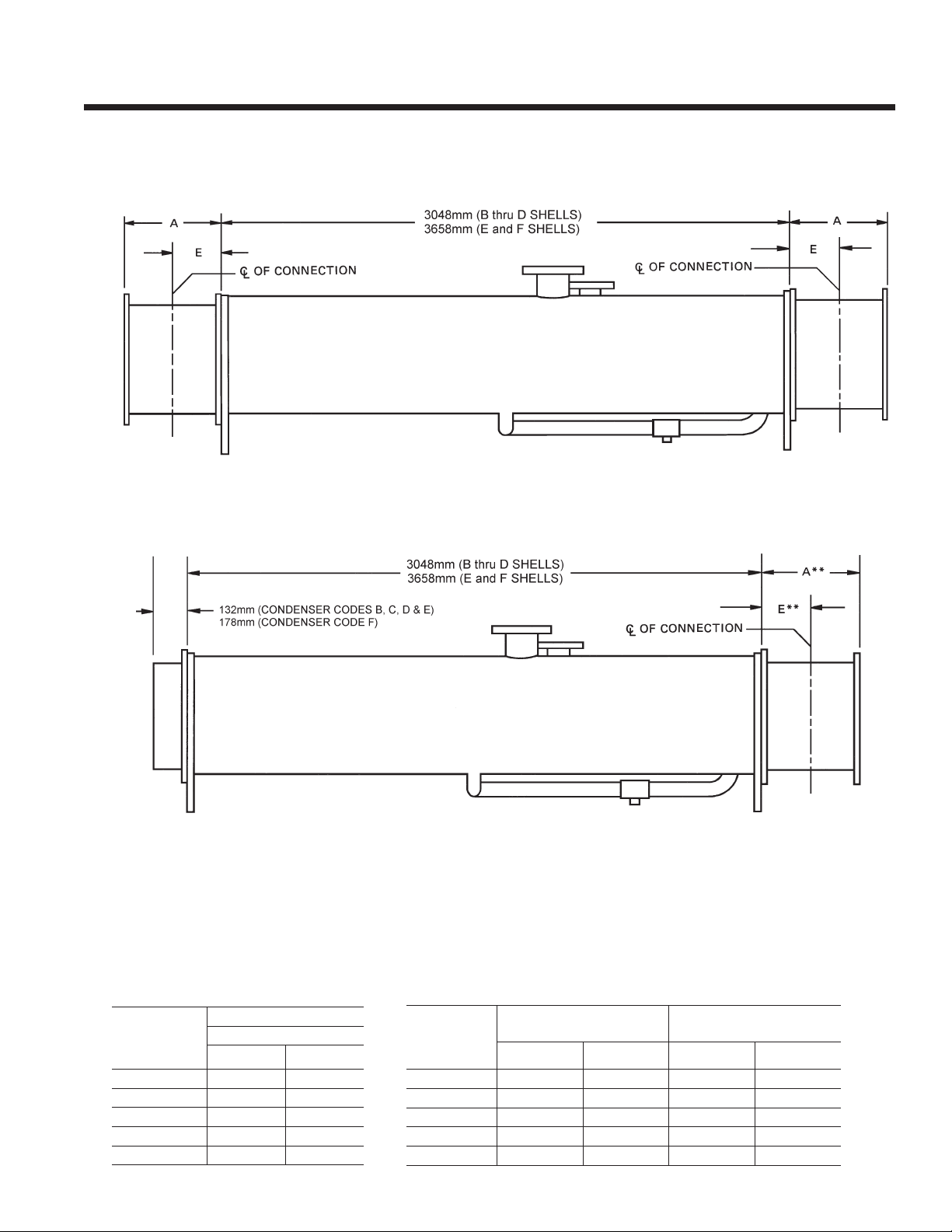
FORM 160.80-EG1 (808)
CONDENSER NOZZLE ARRANGEMENTS – MARINE WATER BOXES
R-22 & R-134a UNITS
MOTOR END
MOTOR END
COMPR. END
1-PASS
*
*
COMPR. END
2-PASS
* Applies to compressor end if connections are on motor end.
** Applies to motor end if connections are on motor end.
CONDENSER NOZZLE SIZES
CondEnsEr
CodE
B
C
d
E
F
noZZLE sIZE (In.)
no. oF PassEs
1 2
8 6
10 8
12 10
12 10
14 12
WEIGHTS (To be added to Metric Unit Weights on pages 46-
CondEnsEr
CodE
B
C
d
E
F
shIPPInG WEIGht
InCrEasE – KGs
1-Pass 2-Pass 1-Pass 2-Pass
246 110 338 149
312 149 463 216
372 144 561 212
372 144 561 212
456 209 721 320
oPEratInG WEIGht
InCrEasE – KGs
47JOHNSON CONTROLS
Page 48

Weights – Metric - continued
R-22 & R-134a UNITS
50 AND 60 HERTZ
REFRIGREFRIG-
SHELL
CHARGE
COOLER
– COND.
BA-BA S0 3,805 4,091 222 200
BA-BB S0 3,873 4,189 222 200
BB-BA S0 3,853 4,167 209 188
BB-BB S0 3,921 4,265 209 188
BA-CA S0 4,147 4,534 236 212
BA-CB S0 4,271 4,712 236 212
BB-CA S0 4,205 4,620 218 196
BB-CB S0 4,330 4,799 218 196
CA-BA S0 4,217 4,574 281 253
CA-BB S0 4,286 4,672 281 253
CB-BA S0 4,322 4,723 281 253
CB-BB S0 4,390 4,820 281 253
CA-CA S0 4,541 4,999 295 265
CA-CB S0 4,665 5,177 295 265
CB-CA S0 4,646 5,147 295 265
CB-CB S0 4,770 5,325 295 265
BA-BA S1 3,835 4,121 222 200
BA-BB S1 3,905 4,219 222 200
BB-BA S1 3,883 4,197 209 188
BB-BB S1 3,951 4,295 209 188
BA-CA S1 4,177 4,524 236 212
BA-CB S1 4,301 4,742 236 212
BB-CA S1 4,235 4,650 218 196
BB-CB S1 4,360 4,829 218 196
CA-BA S1 4,247 4,604 281 253
CA-BB S1 4,315 4,702 281 253
CB-BA S1 4,352 4,753 281 253
CB-BB S1 4,420 4,850 281 253
CA-CA S1 4,571 5,029 295 265
CA-CB S1 4,695 5,207 295 265
CB-CA S1 4,676 5,177 295 265
CB-CB S1 4,800 5,355 295 265
BA-BA S2 4,782 5,069 — 200
BA-BB S2 4,850 5,167 — 200
BB-BA S2 4,830 5,145 — 188
BB-BB S2 4,898 5,243 — 188
BA-CA S2 5,125 5,473 — 212
BA-CB S2 5,249 5,691 — 212
BB-CA S2 5,183 5,598 — 196
BB-CB S2 5,308 5,777 — 196
CA-BA S2 5,195 5,553 — 253
CA-BB S2 5,264 5,650 — 253
CB-BA S2 5,299 5,700 — 253
CB-BB S2 5,367 5,798 — 253
CA-CA S2 5,509 5,967 308 278
CA-CB S2 5,633 6,145 308 278
CODE
COM-
PRES-
SOR
SHIP- OPER-
PING ATING
WT. WT.
(Kgs.) (Kgs.)
ERANT ERANT
CHARGE
(Kgs. (Kgs.
R-22) R-134a)
REFRIG- REFRIG-
SHELL
COOLER
– COND.
CA-DA S2 6,059 6,697 340 306
CA-DB S2 6,293 7,034 340 306
CB-DA S2 6,164 6,846 340 306
CB-DB S2 6,398 7,182 340 306
DA-CA S2 6,030 6,568 381 343
DA-CB S2 6,159 6,746 381 343
DB-CA S2 6,200 6,808 381 343
DB-CB S2 6,324 6,985 381 343
DC-CA S2 6,362 7,054 381 343
DC-CB S2 6,486 7,232 381 343
DA-DA S2 6,599 7,314 431 388
DA-DB S2 6,834 7,650 431 388
DB-DA S2 6,745 7,533 413 371
DB-DB S2 6,979 7,869 413 371
DC-DA S2 6,902 7,909 381 343
DC-DB S2 7,136 7,612 381 343
CA-CA S3 5,606 6,066 — 278
CA-CB S3 5,730 6,243 — 278
CB-CA S3 5,711 6,213 — 278
CB-CB S3 5,836 6,391 — 278
CA-DA S3 6,157 6,796 — 306
CA-DB S3 6,391 7,133 — 306
CB-DA S3 6,261 6,946 — 306
CB-DB S3 6,497 7,282 — 306
DA-CA S3 6,122 6,656 381 343
DA-CB S3 6,246 6,833 381 343
DB-CA S3 6,287 6,895 381 343
DB-CB S3 6,411 7,073 381 343
DC-CA S3 6,450 7,141 381 343
DC-CB S3 6,573 7,319 381 343
DA-DA S3 6,687 7,401 431 388
DA-DB S3 6,921 7,737 431 388
DB-DA S3 6,832 7,620 413 371
DB-DB S3 7,066 7,957 413 371
DC-DA S3 6,989 7,862 381 343
DC-DB S3 7,224 8,198 381 343
DA-CA S4 7,742 8,277 — 336
DA-CB S4 7,866 8,455 — 336
DB-CA S4 7,907 8,517 — 336
DB-CB S4 8,031 8,695 — 336
DC-CA S4 8,070 8,764 — 336
DC-CB S4 8,194 8,940 — 336
DA-DA S4 8,307 9,023 — 376
DA-DB S4 8,543 9,360 — 376
DB-DA S4 8,453 9,243 — 363
DB-DB S4 8,688 9,580 — 363
DC-DA S4 8,611 9,486 — 336
DC-DB S4 8,812 9,821 — 336
CODE
COM-
PRES-
SOR
SHIP- OPER-
PING ATING
WT. WT.
(Kgs.) (Kgs.)
ERANT ERANT
CHARGE CHARGE
(Kgs. (Kgs.
R-22) R-134a)
48 JOHNSON CONTROLS
Page 49
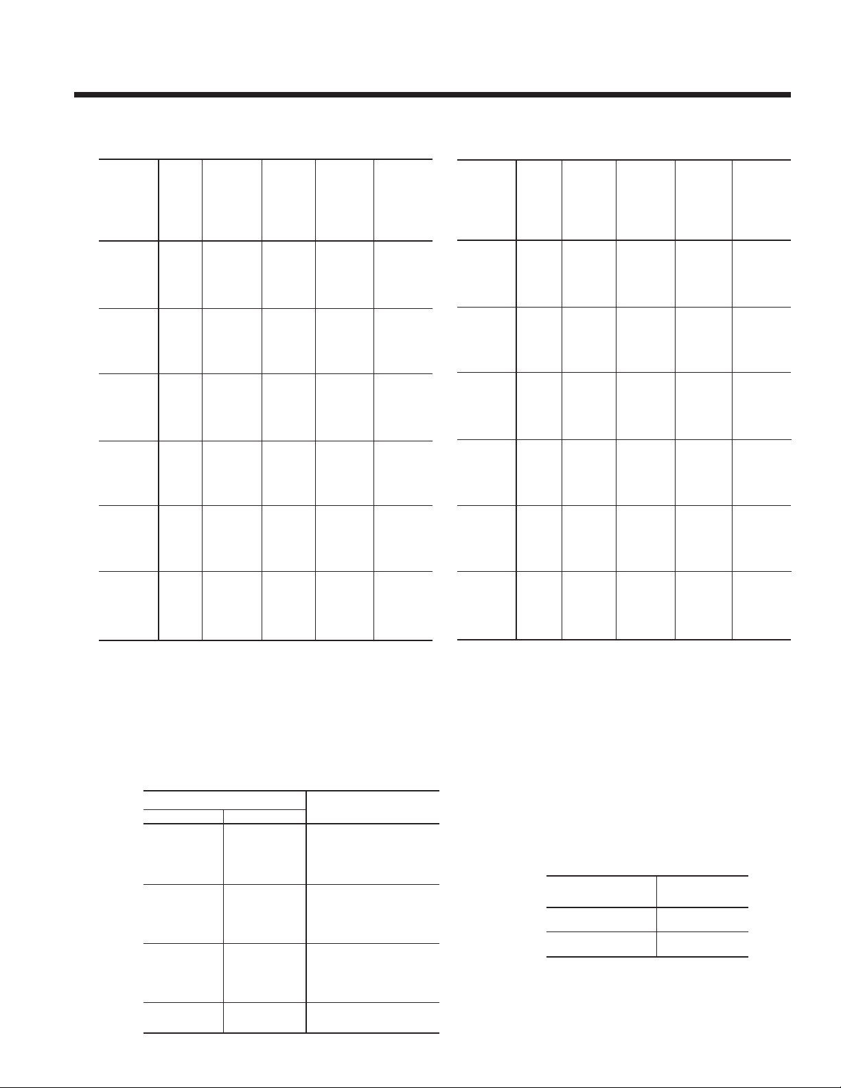
R-22 & R-134a UNITS
50 AND 60 HERTZ
FORM 160.80-EG1 (808)
REFRIG- REFRIG-
SHELL
CODE
COOLER
– COND.
COM-
PRES-
SOR
SHIP- OPER-
PING ATING
WT. WT.
(Kgs.) (Kgs.)
ERANT ERANT
CHARGE CHARGE
(Kgs. (Kgs.
R-22) R-134a)
EA-EA S4 9,281 9,929 635 572
EA-EB S4 9,573 10,316 635 572
EB-EA S4 9,505 10,199 612 551
EB-EB S4 9,767 10,586 612 551
EC-EA S4 9,690 10,496 590 531
EC-EB S4 9,979 10,882 590 531
EA-FA S4 10,653 11,609 689 621
EA-FB S4 11,202 12,334 689 621
EB-FA S4 10,847 11,875 689 621
EB-FB S4 11,394 12,601 658 592
EC-FA S4 11,060 12,175 658 592
EC-FB S4 11,609 12,898 658 592
FA-EA S4 10,397 11,339 — 767
FA-EB S4 10,722 11,727 — 767
FB-EA S4 10,755 11,749 — 767
FB-EB S4 11,017 12,137 — 767
FC-EA S4 10,964 12,282 — 735
FC-EB S4 11,404 12,669 — 735
FA-FA S4 11,783 12,998 907 816
FA-FB S4 12,332 13,724 907 816
FB-FA S4 12,078 13,405 907 816
FB-FB S4 12,624 14,131 862 776
FC-FA S4 12,314 13,939 862 776
FC-FB S4 13,013 14,662 862 776
REFRIG- REFRIG-
SHELL
CODE
COOLER
– COND.
COM-
PRES-
SOR
SHIP- OPER-
PING ATING
WT. WT.
(Kgs.) (Kgs.)
ERANT ERANT
CHARGE CHARGE
(Kgs. (Kgs.
R-22) R-134a)
EA-EA S5 9,424 10,074 — 572
EA-EB S5 9,717 10,462 — 572
EB-EA S5 9,650 10,345 — 551
EB-EB S5 9,913 10,742 — 551
EC-EA S5 9,835 10,642 — 531
EC-EB S5 10,125 11,030 — 531
EA-FA S5 10,799 11,757 — 621
EA-FB S5 11,349 12,484 — 621
EB-FA S5 10,995 12,024 — 621
EB-FB S5 11,542 12,752 — 592
EC-FA S5 11,207 12,325 — 592
EC-FB S5 11,757 13,050 — 592
FA-EA S5 10,557 11,467 — 767
FA-EB S5 10,850 11,855 — 767
FB-EA S5 10,882 11,877 — 767
FB-EB S5 11,144 12,264 — 735
FC-EA S5 11,092 12,409 — 735
FC-EB S5 11,532 12,797 — 735
FA-FA S5 11,910 13,125 907 816
FA-FB S5 12,459 13,851 907 816
FB-FA S5 12,205 13,532 907 816
FB-FB S5 12,751 14,258 862 776
FC-FA S5 12,591 14,066 862 776
FC-FB S5 13,140 14,789 862 776
NOTE: 1. Calculate total chiller weight by adding motor weight, solid state starter weight, and marine water box weights, if applicable.
2. Shipping weight includes refrigerant and oil charge. Operating weight includes water in tubes and water boxes.
3. Weights based on standard tubes in evaporators and condensers.
MOTOR WEIGHTS
MOTOR CODE WEIGHT
60 Hz 50 Hz
CF 5 CC 490
CG 5 CC 490
CH 5 CD 508
CJ 5 CE 508
CK 5 CF 662
CL 5 CG 689
CM 5 CH 875
CN 5 CI 875
CP 5 CJ 898
CR 5 CK 898
CS 5 CL 1,075
CT 5 CM 1,125
CU 5 CN 1,125
CV 5 CO 1,195
(Kgs)
SOLID STATE STARTER
WEIGHT
SIZE Kgs
7L, 14L 91
26L, 33L 136
49JOHNSON CONTROLS
Page 50

Guide Specications
GENERAL
Furnish and install where indicated on the drawings
YORK Millennium Rotary Screw Liquid Chilling Units(s).
Each unit shall produce a capacity of tons, cooling
GPM of from °F to °F when supplied
with GPM of condenser water at °F. Power
input shall not exceed kW with an IPLV (APLV)
of . The evaporator shall be selected for ft2
°F hr/BTU fouling factor and a maximum liquid pressure
drop of ft. Water side shall be designed for 150
psig working pressure. The condenser shall be selected
for fouling factor and maximum liquid pressure
drop of ft. Water side shall be designed for 150 psig
working pressure. Power shall be supplied to the compressor motor at volts – 3-phase – (60)(50) Hertz and
controls at 115 volts –1-phase – (60)(50) Hertz.
– (or) –
Furnish and install where indicated on the drawings
YORK Millennium Rotary Screw Liquid Chilling Units(s).
Each unit shall produce a capacity of kW, cooling
L/S of from °C to °C when supplied
with L/S of condenser water at °C. Power
input shall not exceed kW with an IPLV (APLV)
of . The evaporator shall be selected for M2
°C/W fouling factor and a maximum liquid pressure drop of
kPa. Water side shall be designed for 1034 kPa working
pressure. The condenser shall be selected for M2
°C/W fouling factor and maximum liquid pressure drop of
kPa. Water side shall be designed for 1034 kPa working
pressure. Power shall be supplied to the compressor
motor at volts – 3-phase – 50 Hertz and controls
at 115 volts – 1-phase – 50 Hertz.
Performance shall be certied or rated in accordance with
the latest edition of ARI Standard 550/590-98 as appli-
cable. Only chillers that are listed in the ARI Certication
Program for Water Chilling Packages using the vapor
compression cycle are acceptable.
Each unit shall be completely factory packaged including
evaporator, condenser, subcooler, oil separator, compressor, open motor, lubrication system, OptiView Control
Center, Solid State Starter, refrigerant isolation valves
and all interconnecting piping and wiring. The factory
package shall consist of a “Leaktight” design, with no pipe
thread connections that can loosen and leak over time. All
units shall ship with a full charge of refrigerant (HCFC-22
or HFC-134a) and oil. (Alternatively, the chiller shall be
shipped with the compressor, control panel and oil separator removed (Form 3) or also with the shells separated
(Form 7) to allow rigging into the equipment room. All units
that ship disassembled shall be assembled and factory
run tested prior to disassembly and shipment).
Compressor
The compressor shall be an open-drive, rotary-screw type.
The compressor housing shall be of cast iron, precision
machined to provide minimal clearance for the rotors. The
rotors shall be manufactured from forged steel and use
asymmetric proles operating at a maximum speed of
(3570 RPM/60 Hz) (2975 RPM/50 Hz). The compressor
shall incorporate a complete anti-friction bearing design
to reduce power and increase reliability; four separate
cylindrical roller bearings to handle radial loads; and two
4-point angular contact ball bearings to handle axial loads.
A spring actuated positive seating check valve shall be
incorporated in the compressor housing to prevent rotor
backspin during shutdown. The open-drive compressor shaft seal consists of a bellows-type spring loaded
precision lapped ceramic ring, Teon® static seal, and a
precision lapped ceramic rotating collar. The seal cavity is
maintained at intermediate pressure with its oil discharged
to the oil drain from the compressor. Combining intermedi-
ate pressure with direct oil injection provides cool, non-
foaming lubricant to the seal which assures a long life.
Capacity control shall be achieved by use of a slide valve
to provide fully modulating control from 100% to 10% of
full load. The slide valve shall be actuated by oil pressure, controlled by external solenoid valves through the
OptiView Control Center. The unit shall be capable of
operating with lower temperature cooling tower water during part-load operation in accordance with ARI Standard
550/590. If the unit can not operate at the minimum load,
the manufacturer shall provide a hot-gas-bypass system
to allow operation at 10% load, and advise the minimum
load and power input of the unit at the point hot-gas-bypass is actuated.
Lubrication System
An adequate supply of oil shall be available to the compressor at all times. During start-up and coastdown, this
shall be achieved by oil reservoirs in the compressor.
During operation, oil shall be delivered by positive system
pressure differential.
50 JOHNSON CONTROLS
Page 51

FORM 160.80-EG1 (808)
All chillers shall be provided with a single oil lter housing with isolation valves. An optional dual lter is available which allows immediate switching from one lter
to the other, eliminating downtime during lter changes.
The off-line oil lter must be capable of being changed
during chiller operation. The chiller shall ship with a 3
micron absolute oil lter, (two lters for dual lter option)
maintaining a clean oil system and ensuring superior
compressor life.
A 1500W immersion oil heater shall be provided and
temperature actuated to effectively remove refrigerant
from the oil. Power wiring to the Control Center shall be
factory installed. The oil cooler shall be refrigerant cooled
and factory piped, requiring no auxiliary water or refrig-
erant piping in the eld. An oil eductor shall be provided
to automatically remove oil which may have migrated to
the evaporator and return it to the compressor. The oil
separator shall be of a horizontal design with no moving
parts, and shall provide effective oil separation before the
refrigerant enters the heat exchangers. The oil separator
shall be designed, tested and stamped in accordance
with ASME Boiler and Pressure Vessel Code, Section VIII
– Division 1 (A.D. Merkblatter or other European Pressure
Vessel Code).
Motor Driveline
Evaporator shall be of the shell-and-tube, ooded type
designed for 300 psig (2069 KPa) working pressure on
the refrigerant side. Shell shall be fabricated from rolled
carbon steel plate with fusion welded seams; have carbon
steel tube sheets, drilled and reamed to accommodate
the tubes; and intermediate tube supports spaced no
more than four feet apart. The refrigerant side shall be
designed, tested and stamped in accordance with ASME
Boiler and Pressure Vessel Code, Section VIII – Division
1 (A.D. Merkblatter or other European Pressure Vessel
Code). When required by the refrigeration safety code,
the vessel shall have a refrigerant relief device(s) set at
300 psig (2069 KPa). Tubes shall be high-efciency, internally enhanced type. Each tube shall be roller expanded
into the tube sheets providing a leak-proof seal, and be
individually replaceable. Water velocity through the tubes
shall not exceed 12 FPS (3.6 m/s). Liquid level sight glass
shall be located on the side of the shell to aid in determining proper refrigerant charge.
Water boxes shall be removable to permit tube cleaning and replacement. Stubout water connections having
ANSI/AWWA C-606 grooves shall be provided. Water
boxes shall be designed for 150 psig (1034 KPa) design
working pressure and be tested at 225 psig (1551 KPa).
Vent and drain connections with plugs shall be provided
on each water box.
The compressor motor shall be an open drip-proof, squirrel-cage, induction type operating at 3570 RPM (2975
RPM for 50 Hz operation).
The open motor shall be provided with a D-ange, bolted
to a cast-iron adaptor mounted on the compressor to allow
the motor to be rigidly coupled to the compressor to provide factory alignment of motor and compressor shafts.
Motor drive shaft shall be directly connected to the
compressor shaft with a exible disc coupling. Coupling
shall have all metal construction with no wearing parts
to assure long life, and no lubrication requirements to
provide low maintenance. For units utilizing remote electromechanical starters, a large steel terminal box with
gasketed front access cover shall be provided for eld
connected conduit. Overload/overcurrent transformers
shall be furnished with all units. (For units furnished
with factory packaged Solid State Starters, refer to the
“Options” section.)
Evaporator
Condenser
Condenser shall be of the shell-and-tube type, designed
for 300 psig (2069 KPa) working pressure on the refrigerant side. Shell shall be fabricated from rolled carbon steel
plate with fusion welded seams; have carbon steel tube
sheets, drilled and reamed to accommodate the tubes;
and intermediate tube supports spaced no more than four
feet apart. A refrigerant subcooler shall be provided for
improved cycle efciency. The refrigerant side shall be
designed, tested and stamped in accordance with ASME
Boiler and Pressure Vessel Code, Section VIII – Division
1 (A.D. Merkblatter or other European Pressure Vessel
Code). When required by the refrigeration safety code,
the vessel shall have a refrigerant relief device(s) set at
300 psig (2069 KPa). Tubes shall be high-efciency, internally enhanced type. Each tube shall be roller expanded
into the tube sheets providing a leak-proof seal, and be
individually replaceable. Water velocity through the tubes
shall not exceed 12 FPS.
Water boxes shall be removable to permit tube cleaning and replacement. Stubout water connections having
51JOHNSON CONTROLS
Page 52

Guide Specications - continued
ANSI/AWWA C-606 grooves shall be provided. Water
Boxes shall be designed for 150 psig (1034 KPa) design
working pressure and be tested at 225 psig (1551 KPa).
Vent and drain connections with plugs shall be provided
on each water box.
Refrigerant System
The YS chiller is equipped with a refrigerant metering
device consisting of a xed orice and solenoid valve
controlled via the OptiView Control Center. This control
ensures proper refrigerant ow to the evaporator over a
wide range of operating conditions, including thermal storage applications and chilled water reset. Valve operation
is programmable and can be customized for a specic
application via the OptiView Control Center keypad.
The condenser shell shall be capable of storing the entire
system refrigerant charge during servicing. Isolation from
the rest of the system shall be by manually operated isolation valves located at the inlet and outlet of the condenser.
Additional valves shall be provided to facilitate removal of
refrigerant charge from the system.
during ice building operation. In the thermal storage control
mode, the chiller shall stay at 100% load until the setpoint
shutdown temperature is reached. To add greater operat-
ing exibility and eliminate unnecessary chiller cycling,
two different Low Water (Liquid) Temperature Restart
Thresholds shall be programmable, one for the ice mode
and one for the standard cooling mode. The chiller shall
have the capability to remain in the standard control mode
for temperatures between 20 to 70°F (-6.7 to 21.1°C) for
applications involving a process cooling duty that requires
leaving chilled liquid temperature setpoint control.
The chiller control panel shall also provide:
1. System operating information including:
a. Return and leaving chilled water temperature
b. Return and leaving condenser water temp.
c. Evaporator and condenser saturation temp.
d. Oil pressure at compressor and oil lter
differential
e. Percent motor current
OPTIVIEW CONTROL CENTER
General – The chiller shall be controlled by a stand-alone
microprocessor based control center. The chiller control
panel shall provide control of chiller operation and monitoring of chiller sensors, actuators, relays and switches.
Control Panel – The control panel shall include a 10.4in. diagonal color liquid crystal display (LCD) surrounded
by “soft “ keys which are redened based on the screen
displayed at that time. This shall be mounted in the middle
of a keypad interface and installed in a locked enclosure.
The screen shall detail all operations and parameters,
using a graphical representation of the chiller and its
major components. Panel verbiage shall be available in
other languages as an option with English always available. Data shall be displayed in either English or Metric
units. Smart Freeze Point Protection shall run the chiller
at 36°F (2.22°C) leaving chilled water temperature, and
not have nuisance trips on low water temperature. The
sophisticated program and sensor shall monitor the chiller
water temperature to prevent freeze-up. When needed,
Hot Gas Bypass is available as an option. The panel shall
display countdown timer messages so the operator knows
when functions are starting and stopping. Every programmable point shall have a pop-up screen with the allowable
ranges, so that the chiller can not be programmed to
operate outside of its design limits.
f. Evaporator and condenser saturation temp.
g. Compressor discharge temperature
h. Oil temperature
i. Percent slide valve position
j. Operating hours
k. Number of unit starts
2. Digital programming of setpoints through the universal keypad including:
a. Leaving chilled water temperature
b. Percent current limit
c. Pull-down demand limiting
d. Six-week schedule for starting and stopping the
chiller, pumps and tower
e. Remote reset temperature range
3. Status messages indicating:
a. System ready to start
b. System running
c. System coastdown
d. System safety shutdown-manual restart
e. System cycling shutdown-auto restart
The control panel shall be provided with a thermal ice
storage control mode to enhance system performance
52 JOHNSON CONTROLS
f. System prelube
Page 53

FORM 160.80-EG1 (808)
g. Start inhibit
4. The text displayed within the system status and
system details eld shall be displayed as a color
coded message to indicate severity: red for safety
fault, orange for cycling faults, yellow for warnings,
and green for normal messages.
5. Safety shutdowns enunciated through the display and
the status bar, and consist of system status, system
details, day, time, cause of shutdown, and type of
restart required. Safety shutdowns with a xed speed
drive shall include:
a. Evaporator - low pressure
b. Evaporator - low pressure - smart freeze
c. Evaporator - transducer or leaving liquid probe
d. Evaporator - transducer or temperature sensor
e. Condenser - high pressure contacts open
f. Condenser - high pressure
g. Condenser - pressure transducer out of range
h. Auxiliary safety - contacts closed
i. Discharge - high temperature
h. Phase rotation
6. Cycling shutdowns enunciated through the display
and the status bar, and consisting of system status,
system details, day, time, cause of shutdown, and
type of restart required.
Cycling shutdowns with a xed speed drive shall
include:
a. Multiunit cycling - contacts open
b. System cycling - contacts open
c. Control panel - power failure
d. Leaving chilled liquid - low temperature
e. Leaving chilled liquid - ow switch open
f. Condenser - ow switch open
g. Motor controller - contacts open
h. Motor controller - loss of current
i. Power fault
j. Control panel - schedule
6.1 Cycling shutdowns with a Solid State Starter (LCSSS)
shall include:
j. Discharge - low temperature
k. Oil - high temperature
l. Oil - low differential pressure
m. Oil - low differential seal pressure
n. Oil or condenser transducer error
o. Oil - clogged lter
p. Oil- high pressure
q. Oil - separator - low level
r. Control panel - power failure
s. Watchdog - software reboot
5.1. Safety shutdowns with a Solid State Starter (LCSSS)
shall include:
a. Shutdown - requesting fault data...
b. High instantaneous current
c. High phase (X) heatsink temperature - running
d. 105% motor current overload
e. Motor or starter - current imbalance
f. Phase (X) shorted SCR
g. Open SCR
a. Initialization failed
b. Serial communications
c. Requesting fault data
d. Stop contacts open
e. Power fault
f. Low phase (X) temperature sensor
g. Run signal
h. Invalid current scale selection
i. Phase locked loop
j. Low supply line voltage
k. High supply line voltage
l. Logic board processor
m. Logic board power supply
n. Phase loss
7. Security access to prevent unauthorized change
of setpoints, to allow local or remote control of the
chiller, and to allow manual operation of the prerotation vanes and oil pump. Access shall be through ID
and password recognition, which is dened by three
different levels of user competence: view, operator,
53JOHNSON CONTROLS
Page 54

Guide Specications- continued
and service.
8. Trending data with the ability to customize points of
once every second to once every hour. The panel
shall trend up to 6 different parameters from a list of
over 140, without the need of an external monitoring
system.
9. The operating program stored in non-volatile memory
(EPROM) to eliminate reprogramming the chiller due
to AC power failure or battery discharge. Programmed
setpoints shall be retained in lithium battery-backed
RTC memory for a minimum of 11 years with power
removed from the system.
10. A fused connection through a transformer in the
compressor motor starter to provide individual overcurrent protected power for all controls.
11. A numbered terminal strip for all required eld interlock wiring.
12. An RS-232 port to output all system operating data,
shutdown/cycling message, and a record of the last
10 cycling or safety shutdowns to a eld-supplied
printer. Data logs to a printer at a set programmable
interval. This data can be preprogrammed to print
from 1 minute to 1 day.
13. The capability to interface with a building automation
system to provide:
a. Remote chiller start and stop
b. Remote leaving chiller liquid temperature adjust
c. Remote current limit setpoint adjust
d. Remote ready to start contacts
Standard features include: digital readout at the OptiView
Control Center of the following:
Display Only:
• 3-phase voltage A, B, C
• 3-phase current A, B, C
• Input power (kW)
• kW Hours
• Starter Model
• Motor Run (LED)
• Motor Current % Full Load Amps
• Current Limit Setpoints
• Pulldown Demand Time Left
Programmable:
• Local Motor Current Limit
• Pulldown Demand Limit
• Pulldown Demand Time
Other features include: low-line voltage, 115-volt control
transformer; three-leg sensing overloads; phase rotation
and single-phase failure protection; high temperature
safety protection, motor current imbalance and undervoltage safeties; open and close SCR protection; momentary
power interruption protection. The LCSSS is cooled by a
closed loop, fresh water circuit consisting of a water-towater heat exchanger and 1/25 HP circulating pump. All
interconnecting water piping is factory installed and rated
for 150 PSIG working pressure. Optional unit-mounted
circuit breaker includes ground fault protection and provides 65,000 amp. Short circuit withstand rating in accordance with UL Standard 508. A non-fused disconnect
switch is also available. Both options are padlockable.
e. Safety shutdown contacts
f. Cycling shutdown contacts
g. Run contacts
COMPRESSOR MOTOR STARTER
(OPTION, 200 - 600V)
The chiller manufacturer shall furnish a reduced-voltage
Solid State Starter for the compressor motor. Starter
shall be factory-mounted and wired on the chiller. The
starter shall provide, through the use of silicon controlled
rectiers, a smooth acceleration of the motor without
current transitions or transients. The starter enclosure
shall be NEMA 1, with a hinged access door with lock
and key. Electrical lugs for incoming power wiring shall
be provided.
54 JOHNSON CONTROLS
REMOTE ELECTRO-MECHANICAL COMPRESSOR
MOTOR STARTER (OPTIONAL)
A remote electro-mechanical starter of the R-1051 type
shall be furnished for each compressor motor. The starter
shall be furnished in accordance with the chiller manufac-
turer’s starter specications and as specied elsewhere
in these specications.
PORTABLE REFRIGERANT STORAGE/RECYCLING
SYSTEM
A portable, self-contained refrigerant storage/recycling
system shall be provided consisting of a refrigerant compressor with oil separator, storage receiver, water cooled
condenser, lter drier and necessary valves and hoses
to remove, replace and distill refrigerant. All necessary
controls and safety devices shall be a permanent part of
the system.
Page 55

START-UP AND OPERATOR TRAINING
The chiller manufacturer shall include the services of a
factory-trained, eld service representative to supervise
the nal leak testing, charging and the initial start-up and
concurrent operator instruction.
FORM 160.80-EG1 (808)
55JOHNSON CONTROLS
Page 56
Printed on recycled paper
© 2008 Johnson Controls, Inc. P.O. Box 423, Milwaukee, WI 53201 Printed in USA
www.johnsoncontrols.com
Metric Conversion Tables
MEASUREMENT MULTIPLY THIS BY TO OBTAIN THIS
ENGLISH VALUE METRIC VALUE
CAPACITY TONS REFRIGERANT EFFECT (ton) 3.516 KILOWATTS (kW)
POWER KILOWATTS (kW) NO CHANGE KILOWATTS (kW)
HORSEPOWER (hp) 0.7457 KILOWATTS (kW)
FLOW RATE GALLONS / MINUTE (gpm) 0.0631 LITERS / SECONDS (L/s)
LENGTH FEET (ft) 304.8 MILLIMETERS (mm)
INCHES (in) 25.4 MILLIMETERS (mm)
WEIGHT POUNDS (lb) 0.4536 KILOGRAMS (kg)
VELOCITY FEET / SECOND (fps) 0.3048 METERS / SECOND (m/s)
PRESSURE DROP FEET OF WATER (ft) 2.989 KILOPASCALS (k Pa)
POUNDS / SQ. INCH (psi) 6.895 KILOPASCALS (k Pa)
Temperature
To convert degrees Fahrenheit (°F) to degrees Celsius (°C),
subtract 32° and multiply by 5/9 or 0.5556.
To convert a temperature range (i.e., 10°F or 12°F chilled
water range) from Fahrenheit to Celsius, multiply by 5/9
or 0.5556.
Efciency
In the English I-P system, chiller efciency is measured
in kW / ton:
kW / ton =
kW input
tons refrigerant effect
In the SI Metric system, chiller efciency is measured in
Coefcient of Performance (COP).
COP =
kW refrigeration effect
kW input
kW / ton and COP are related as follows:
3.516
kW / ton =
COP =
COP
3.516
kW / ton
Integrated Part Load Value (IPLV)
In the English I-P system, IPLV is calculated by the following
formula. A full explanation is shown on page 4:
1
IPLV* =
0.01
A
+
0.42
B
+
0.45
C
+
0.12
D
Where: A = kW / ton at 100% Load @ 85°F ECFT
B = kW / ton at 75% Load @ 75°F ECFT
C = kW / ton at 50% Load @ 65°F ECFT
D = kW / ton at 25% Load @ 65°F ECFT
In SI Metric, the formula is:
IPLV* = 0.01A + 0.42B + 0.45C + 0.12D
Where: A = COP at 100% Load @ 29.4°C ECFT
B = COP at 75% Load @ 23.9°C ECFT
C = COP at 50% Load @ 18.3°C ECFT
D = COP at 25% Load @ 18.3°C ECFT
* NOTE: The Non-Standard Part-Load Value (NPLV) uses
the IPLV formula with the following exceptions: the ECFT
for part-load points varies linearly from the selected EFT to
65°F (18.3°C) from 100% to 50% loads, and xed at 65°F
(18.3°C) for 50% to 0% loads.
FOULING FACTOR
ENGLISH I-P EQUIVALENT SI METRIC
(ft2 °F hr/BTU) (M2 K/kW)
0.0001 0.018
0.00025 0.044
0.0005 0.088
0.00075 0.132
Form 160.80-EG1 (708) Supersedes 160.80-EG1 (900)
 Loading...