

Page 1
SPLIT-SYSTEM HEAT PUMPS
OUTDOOR UNITS
INSTALLATION INSTRUCTION
Supersedes: 035-16192-000 (0601)
MODELS E1FB180 & E1FB240
O
O
O
O
035-16192-001-A-1001
O
O
O
O
O
O
GENERAL
The outdoor units are completely piped and wired at the fac-
tory and are shipped ready for immediate installation. Only
the interconnecting liquid and suction lines, sight glasses,
control wiring, and the main power wiring are required to
complete the installation. Every unit is dehydrated, evacu
ated, leak tested and pressure tested at 450 psig before be
ing pressurized with a holding charge of refrigerant-22 for
shipment and/or storage.
To eliminate the costly cabinet deterioration problems usually
associated with outdoor equipment, all sheet metal parts are
constructed of commercial grade (G90) galvanized steel. Af
ter fabrication, each part is thoroughly cleaned to remove
any grease or dirt from its surfaces. The parts that will be
exposed to the weather are then coated with a “desert sand”
powder paint to assure a quality finish for many years. This
coating system has passed the 750-hour, salt spray test per
ASTM Standard B117.
Every unit includes 2 heavy-duty scroll compressors, 2 suc
tion line accumulators, 2 4-way reversing valves with a 24
volt solenoid, 2 outdoor fan motors with inherent protection,
and a copper tube/aluminum fin coil that is positioned verti
cally for better drainage of the water that will condense on it
during the heating cycle.
They also include 2 filter driers, 2 expansion valves and dis
tributors that are only used during the heating cycle plus a
check valve to provide the proper flow of refrigerant through
the unit during both the cooling and heating cycles.
All controls are located in the front of the unit and are readily
accessible for maintenance, adjustment and service. All wir-
ing (Power and Control) can be made through the front of
the unit.
-
-
REFERENCE
This instruction covers the installationandoperationoftheba
sic condensing unit. For information on the installationandop
eration of the matching indoor units, refer to Installation
Instruction part no. 035-16626-000 (form 515.41-N4Y).
All accessories come with a separate Installation Manual.
RefertoPartsManualfor complete listingof replacement parts
on this equipment.
All forms may be ordered from:
-
-
Standard Register
Norman, OK 73069
Toll Free: Tel. 877-318-9675/Fax. 877-379-7920
INSPECTION
As soon as a unit is received, it should be inspected for pos
-
sible damage during transit. If damage is evident, the extent
of the damage should be noted on the carrier's freight bill. A
separate request for inspection by the carrier's agent should
be made in writing.
-
-
-
Installershouldpayparticularattention tothewords: NOTE,CAUTIONand WARNING.Notes
installation easier.Cautions
are given to prevent equipment damage. Warnings are given to alert installer that personal
injury and/or equipment damage may result if installation procedure is not handled properly.
areintendedto clarifyormake
Page 2
035-16192-001-A-1001
GENERAL
REFERENCE
INSPECTION
NOMENCLATURE
.............................................................................
.............................................................................
.............................................................................
......................................................................
INSTALLATION
TABLE OF CONTENTS
1
1
1
2
CLEANING
LUBRICATION
REPLACEMENT PARTS
NOTICE TO OWNER
.............................................................................
............................................................................
MAINTENANCE
............................................................
..................................................................
14
14
14
14
LIMITATIONS
LOCATION
Roof-Top Locations
Ground Level Locations
RIGGING AND HANDLING
CLEARANCES
COMPRESSOR CRANKCASE HEATER
POWER AND CONTROL WIRING
Power Wiring
Control Wiring
REFRIGERANT PIPING
General Guidelines
Line Sizing
Service Valves
Installation
EXTENDING THE SERVICE PORTS
EVACUATING AND CHARGING
BALANCE POINT SETTING
ALTERNATE CHARGING METHODS........................................ 10
.............................................................................
.............................................................
......................................................
........................................................
...........................................................................
...................................
......................................................................
.....................................................................
.............................................................
..........................................................................
....................................................................
...........................................................................
.........................................
................................................
.......................................................
OPERATION
GENERAL ............................................................................. 11
SYSTEM SEQUENCE OF OPERATION
Cooling Operation............................................................... 11
Heating Operation............................................................... 12
Defrost Cycle...................................................................... 12
Operation Below 0°F........................................................... 13
Emergency Heat Operation................................................ 13
START-UP
CRANKCASE HEATER (10 Ton Unit Only)
PRE-START CHECK
INITIAL START-UP
SAFETY FEATURES
SECURE OWNER'S APPROVAL
..................................................................
.....................................................................
..................................................................
...............................................
................................
14
14
14
14
14
3
3
3
3
4
4
4
4
7
7
7
7
9
9
9
Figure
No.
1 Center of Gravity
2 Typical Rigging
3 Typical Field Wiring
4 Unit Dimensions & Clearances
5 Extending The Service Ports
6 Refrigerant Flow Diagram
7 Charging Curves EFB180A
8 Charging Curves EFB240A
9 Heating Mode Charging Chart At 4800 CFM
EFB180A
10 Heating Mode Charging Chart At 6000 CFM
EFB180A
11 Heating Mode Charging Chart At 6600 CFM
EFB180A
12 Heating Mode Charging Chart At 6400 CFM....... 17
EFB240A
13 Heating Mode Charging Chart At 7000 CFM....... 18
EFB 240A
14 Heating Mode Charging Chart At 7600 CFM....... 18
EFB 240A
LIST OF FIGURES
Description Page
..................................................
.....................................................
..............................................
............................
................................
....................................
..................................
..................................
.......
.......
.......
10
11
15
15
16
16
17
3
4
5
6
LIST OF TABLES
Table
No.
1 Unit Application Data
2 Physical Data
3 Electrical Data
4 Suction Lines
5 Liquid Lines
6 Refrigerant Line Charge
Description Page
..........................................................
............................................
.......................................................
......................................................
........................................................
.......................................
3
4
5
7
8
8
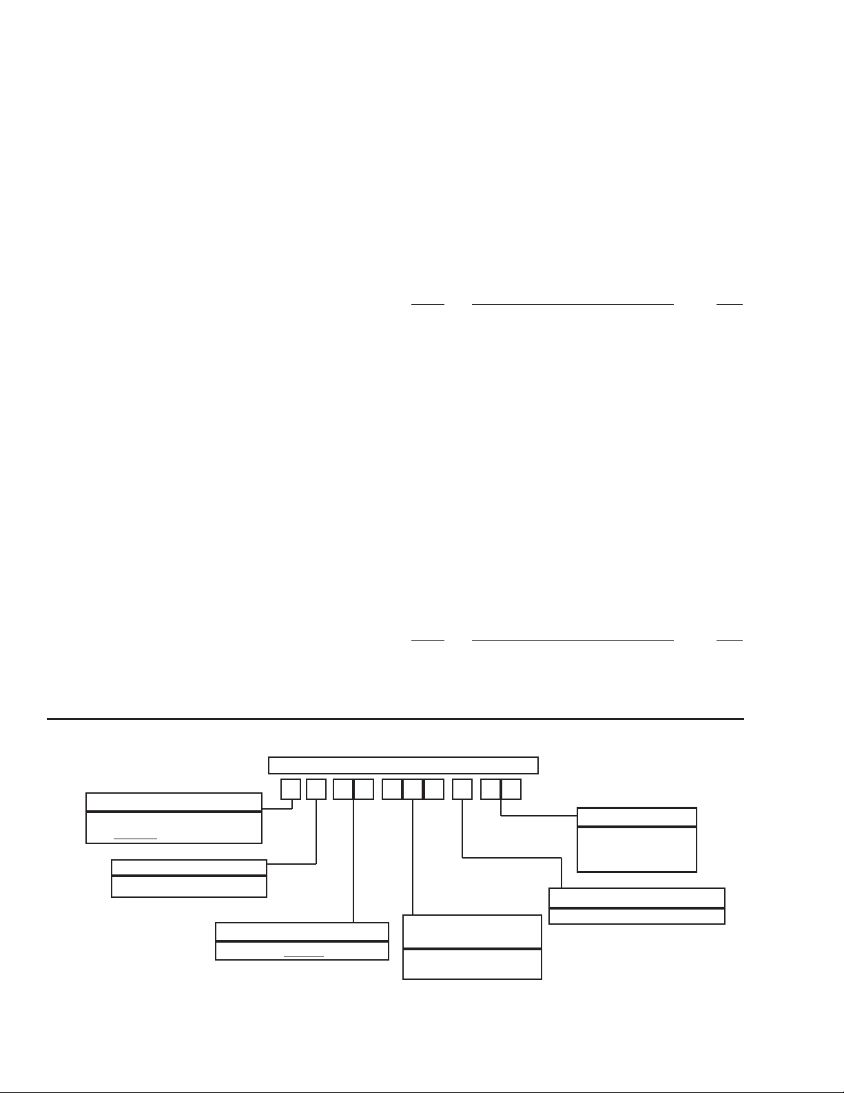
PRODUCT NOMENCLATURE
1 F B 2 58 A
PRODUCT CATEGORY
E = Split-System Heat Pump
Outdoor
2 Unitary Products Group
Unit
PRODUCT GENERATION
1 = First Generation
PRODUCT IDENTIFIER
E
FB = Outdoor Unit
1 0
NOMINAL COOLING
CAPACITY
180 = 15 Ton
240 = 20 Ton
VOLTAGE CODE
25 = 208/230-3-60
46 = 460-3-60
FACTORYINSTALLED HEAT
A = Not Applicable
Page 3
INSTALLATION
035-16192-001-A-1001
LIMITATIONS
These units must be installed in accordance with all national
andlocal safetycodes. Ifno localcodes apply,installationmust
conform with the appropriate national codes. See Table 1 for
Thesebeamscan usuallybeset directlyonthe roof.Flashingis
not required.
NOTE: On bonded roofs, check for special installation re
quirements.
unit application data. Units are designed to meet National
SafetyCodeStandards.Ifcomponents aretobe addedtoa unit
to meet local codes, they are to be installed at the dealer's
and/or the customer's expense.
TABLE 1 - UNIT APPLICATION DATA
APPLICATION LIMITATIONS MIN MAX
Voltage Variation (208/230-3-60) - Volts
Voltage Variation (460-3-60) - Volts
Ambient Air on Outdoor Coil (Cooling Cycle) - °F 45 115
Ambient Air on Indoor Coil (Cooling Cycle) - °F 68 86
Ambient Air on Outdoor Coil (Heating Cycle) - °F 0
Ambient Air on Indoor Coil (Heating Cycle) - °F 60 80
1
Rated in accordance with ARI Standard 110, utilization range “A”.
2
Below 0 °F, the control circuit will lock out the compressor and allow the
electric heat accessory to cycle at its standby capacity.
2
2
187 253
414 506
1
70
LOCATION
Use the following guidelines to select a suitable location for
GROUND LEVEL LOCATIONS
The units must be installed on a substantial base that will not
settle. Any strain on the refrigerant lines may cause a refriger
antleak. Aone-piececoncrete slabwith footersthat extendbe
low the frost line is recommended. The slab should not be tied
tothe buildingfoundation becausenoise and vibrationwill tele
graph.
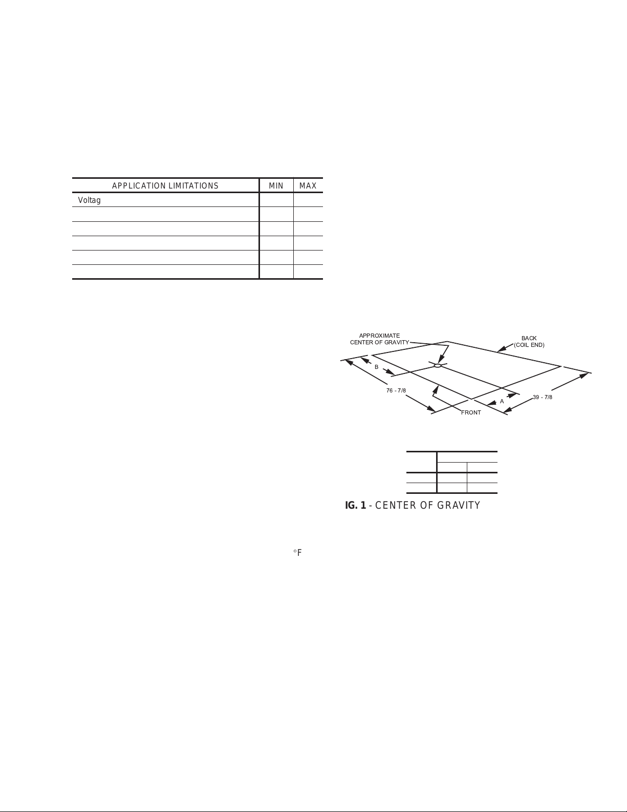
A unit can also be supported by concrete piers. These piers
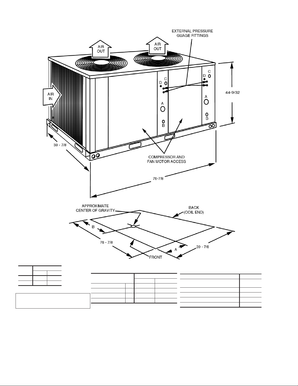
should:(1) extend below the frostline, (2) be located underthe
unit's four corners and (3) be sized to carry the entire unit
weight. Refer to Figure 1 and Table 2 for the center of gravity
and unit weight.
Agravel bed or some other means of handling the condensate
thatwill drop fromthe underside ofthe unit coil duringthe heat
ing and defrost cycles may have to be provided.
APPROXIMATE
CENTER OF GRAVITY
B
BACK
(COIL END)
these units.
1. The outdoor units must be installed outside the building.
Theoutdoor fansare the propellertype andare not suitable
for use with duct work.
76 - 7/8
FRONT
A
39 - 7/8
2. The outdoor and indoor units should be installed as close
together as possible and with a minimum number of bends
in the refrigerant piping. Refer to REFRIGERANT PIPING
for additional information.
3. The outdoor unit should not be installed beneath windows
orbetween structureswhere normal operating sounds may
be objectionable.
WARNING: The outdoor unit should not be installed in an area
wheremud and/or ice could causepersonal injury.
Remember that condensate will drip from the un
dersideof the unit coilsduring heat and defrost cy
cles and that this condensate will freeze when the
temperature of the outdoor air is below 32°F.
4. Allunitsrequire certainclearancesfor properoperation and
Unit
15 Ton 16 38
20 Ton 16 38
FIG. 1 - CENTER OF GRAVITY
CAUTION: Care should be taken to protect the unit from
-
-
tampering and unauthorized persons from injury.
Screws on access panels will prevent casual
tampering. Additional safety precautions such as
fences around the unit or locking devices on the
panels may be advisable. Check local authori
ties for safety regulations.
Dim. (in.)
AB
-
service.
On either rooftop or ground level installations, rubber padding
can be applied between the base rails and their supports to
lessen any transmission of vibration.
ROOF-TOP LOCATIONS
Becarefulnot todamage theroof. Consultthe buildingcontrac
tororarchitect iftheroof isbonded. Choosealocation withade
quate structural strength to support the unit.
The unit must be mounted on solid level supports. The sup
ports can be channel iron beams or wooden beams treated to
reduce deterioration.
Aminimum of two (2) beams are required to support each unit.
The beams should: (1) Be positioned perpendicular to the roof
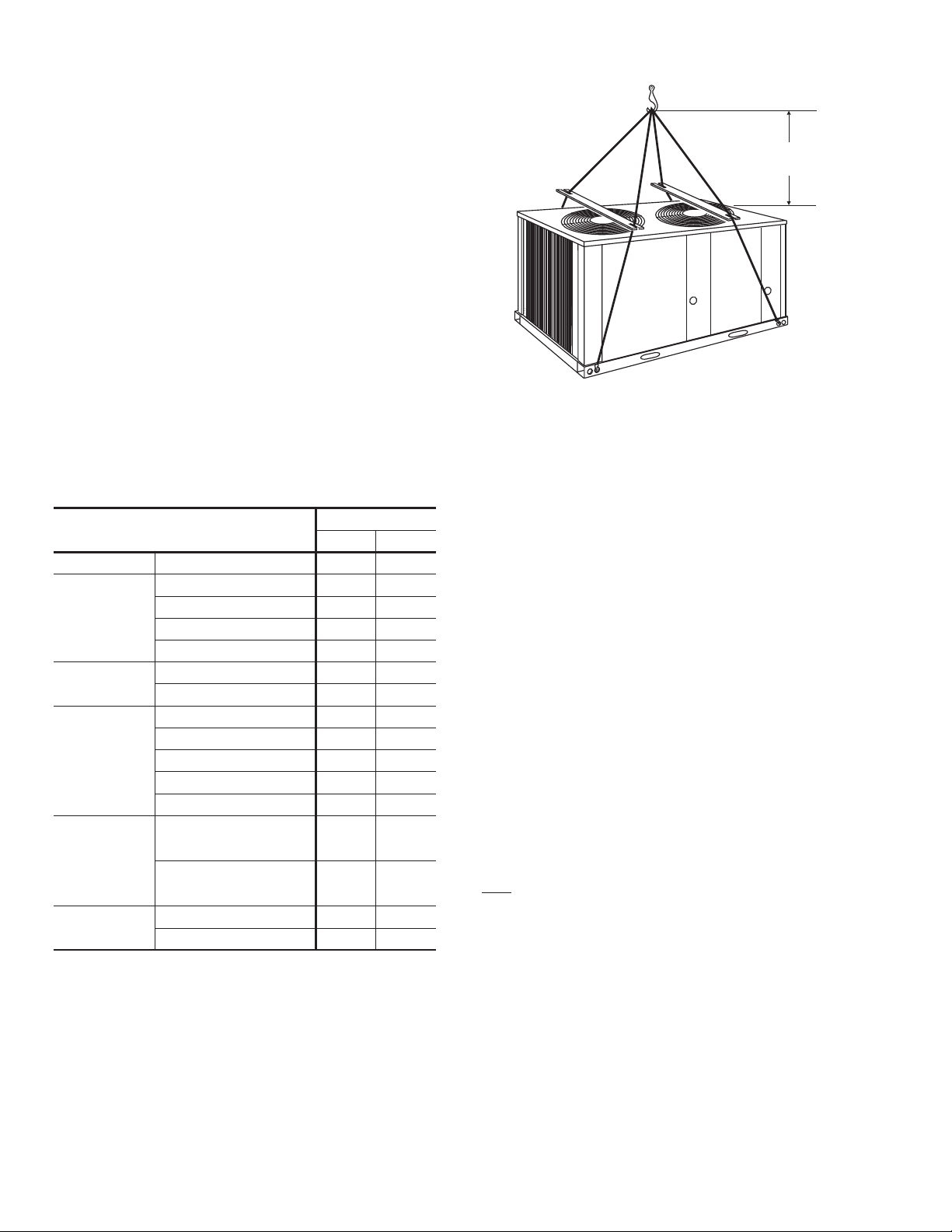
RIGGING AND HANDLING
Exercise care when moving the unit. Do not remove any pack
aging until the unit is near the place of installation.
Rigthe unit by attaching chainor cable slings with hooks tothe
round lifting holes provided in the base rails.
-
-
CAUTION: Spreaders, longer than the largest dimension
-
WARNING: BEFORE LIFTING A UNIT, MAKE SURE THAT
across the unit, MUST be used across the top of
the unit. See Figure 2.
ITS WEIGHT IS DISTRIBUTED EQUALLY ON
THE CABLES SO THAT IT WILLLIFT EVENLY.
joists.(2)Extend beyondthedimensions ofthe unit todistribute
the load on the roof, (3) Be capable of adequately supporting
theentire unitweight. Refer toFigure 1and Table2 for loaddis
tribution and weights.
Unitary Products Group 3
Units may also be moved or lifted with a fork-lift from the front,
-
rear or the compressor end only through the slotted openings
provided in the base rails.
-
-
-
-
-
-
Page 4
035-16192-001-A-1001
O
O
O
O
O
O
O
O
O
O
CAUTION: LENGTH OF FORKS MUST BE A MINIMUM OF
54" (when lifting from the compressor end of the
unit)and a MINIMUMOF 42"(when lifting fromthe
front or rear of the unit).
Remove the nesting brackets from the four corners on top of
the unit. All screws that are removed to take these brackets off
must be replaced on the unit.
CLEARANCES
5 ft.
MIN
All units require certain minimum clearances for proper opera
-
tion and service. Refer to Figure 4 for these clearances.
WARNING: Do not permit overhanging structures or shrubs
to obstruct air discharge.
Additional height may be required for snow clearance if winter
operation is expected.
COMPRESSOR CRANKCASE HEATER
The compressor is equipped with a crankcase heater to pre
vent refrigerant from mixing with crankcase oil during the
“OFF” cycle. The heaters will be energized when the com
pressor is not running providing the unit disconnect switch is
closed.
TABLE 2 - PHYSICAL DATA
DESCRIPTION
1
Compressor
Rating - (Qty) Tons (2) 7-1/2 (2) 10
Quantity 2 2
Fans
Diameter - inches 24 26
Blades/Pitch (°) 3/32 3/36
Nominal CFM 10862 11395
HP 1 1
Fan Motors
2
RPM 1100 1100
Rows Deep X Rows High 2 X 40 2 X 40
Finned Length - inches 130 130
Face Area - square feet 36.11 36.11
Tube(Copper) OD - inches 3/8 3/8
Fins (Aluminum) per inch 18 20
Holding Charge
(Sys 1 / Sys 2)
3
Operating Charge
(Sys 1 / Sys 2)
4
Shipping 970 1020
Operating 980 1040
1
These compressors are fully hermetic.
2
The ball bearing, 48 frame, single phase condenser fan motor have internal
protection and are directly connected to the condenser fins. Motor rotation is
counterclockwise when viewing the lead end, which is opposite the shaft end.
3
The amount of charge in the unit as shipped from the factory.
4
Totaloperatingchargeforthecondensingunit,matchingindoor unit, and 25 feet
of interconnecting pipe.
CAUTION: Do not attempt to start the compressor without at
leasteight hours of crankcase heat or compressor
damage will occur.
4 Unitary Products Group
UNIT MODEL
EFB180 EFB240
1-0/1-0 1-0/1-0
16-8/17-8 19-0/19-0
FIG. 2 - TYPICAL RIGGING
-
-
Ifa unit hasjust beeninstalled orthe unitdisconnect switchhas
beenopen fora longperiod of time,move thesystem switch on
the room thermostat to the “OFF” position before closing the
unit disconnect switch. Eight hours of crankcase heat are re
quired to drive the liquid refrigerant out of the compressor bef
ore the compressor can be started.
POWER AND CONTROL WIRING
Install electrical wiring in accordance with the latest National
Electrical Code (NFPAStandard No. 70) and/or local regulations. The unit should be grounded in accordance with these
codes.
POWER WIRING
Check the voltage of the power supply against the data on
the unit nameplate. Check the size of the power wire, the
disconnect switch and the fuses against the data in Table 3.
NOTE: Copper conductors must be installed between the dis
connect switch and the unit.
Refer to Figure 4 for the location of the power wire access
opening through the front of the unit. This opening will re
quire a field-supplied conduit fitting.
The field-supplied disconnect switch must be suitable for an
outdoor location. Although it should be installed near the unit,
do NOT
secure it to the unit cabinet.
Refer to Figure 3 for typical field wiring.
CONTROL WIRING
Refer to Figure 4 for the location of the control wire access
opening through the front of the unit.
Route the necessary low voltage control wires from terminal
block TB2 of the unit control box through this access open
ing to the indoor unit and to the room thermostat. Refer to
Figure 3 for typical field wiring.
The room thermostat should be mounted about 5 feet above
the floor and located where it will be exposed to normal room
air circulation. Do not locate it on an outside wall, near a
supply air grille, or where it may be affected by sunlight
-
-
-
-
-
Page 5
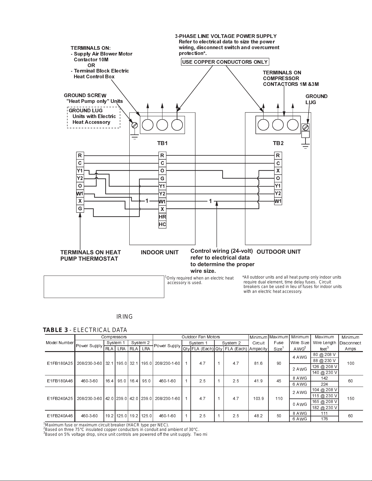
TERMINALS ON:
- Supply Air Blower Motor
Contactor 10M
OR
- Terminal Block Electric
Heat Control Box
035-16192-001-A-1001
3-PHASELINEVOLTAGEPOWERSUPPLY
Refer to electrical data to size the power
wiring, disconnect switch and overcurrent
protection*.
USE COPPER CONDUCTORS ONLY
TERMINALS ON
COMPRESSOR
CONTACTORS 1M &3M
GROUND SCREW
"Heat Pump only" Units
GROUND LUG
Units with Electric
Heat Accessory
R
C
Y1
Y2
O
W1
X
G
TERMINALS ON HEAT
INDOOR UNIT
PUMP THERMOSTAT
WIRE IN ACCORDANCE WITH LOCAL
AND NATIONAL ELECTRICAL CODES
TB1 TB2
R
C
O
G
Y1
Y2
1
W1
1
X
HR
HC
Control wiring (24-volt)
refer to electrical data
to determine the proper
1
Only required when an electric heat
accessory is used.
wire size.
*All outdoor units and all heat pump only indoor units
require dual element, time delay fuses. Circuit
breakers can be used in lieu of fuses for indoor units
with an electric heat accessory.
GROUND
LUG
R
C
X
O
Y1
Y2
W1
OUTDOOR UNIT
FIG. 3 - TYPICAL FIELD WIRING
TABLE 3 - ELECTRICAL DATA
Model Number
E1FB180A25 208/230-3-60 32.1 195.0 32.1 195.0 208/230-1-60 1 4.7 1 4.7 81.6 90
E1FB180A46 460-3-60 16.4 95.0 16.4 95.0 460-1-60 1 2.5 1 2.5 41.9 45 60
E1FB240A25 208/230-3-60 42.0 239.0 42.0 239.0 208/230-1-60 1 4.7 1 4.7 103.9 110
E1FB240A46 460-3-60 19.2 125.0 19.2 125.0 460-1-60 1 50 602.5 1 2.5 48.2
1
Maximum fuse or maximum circuit breaker (HACR type per NEC).
2
Based on three 75°C insulated copper conductors in conduit and ambient of 30°C.
3
Based on 5% voltage drop, since unit controls are powered off the unit supply. Two minute time delay between system 1 and system 2.
Power Supply Power Supply
Compressors Outdoor Fan Motors
System 1 System 2
RLA LRA RLA LRA Qty FLA (Each) Qty FLA (Each)
System 1 System 2
Minimum
Ampacity
Unitary Products Group 5
Circuit
Maximum
Fuse
1
Size
Minimum
Wire Size
AWG
4AWG
2AWG
8 AWG 142
6 AWG 224
2AWG
0AWG
8 AWG 111
6 AWG 176
Maximum
Wire Length
2
80 @ 208 V
88 @ 230 V
126 @ 208 V
140 @ 230 V
104 @ 208 V
115 @ 230 V
165 @ 208 V
182 @ 230 V
feet
3
Minimum
Disconnect
Amps
100
150
Page 6
035-16192-001-A-1001
Unit
Dim. (in.)
AB
15 Ton 16 38
20 Ton 16 38
CENTER OF GRAVITY
Connection
Entry
Suction Line A 1-1/8 ID 1-3/8 ID
Liquid Line B 5/8 ID 5/8 ID
All dimensions are in inches. They are
subject to change without notice. Certified
dimensionswillbeprovideduponrequest.
Power Wiring C 2-1/8 KO 2-1/8KO
Control Wiring D 7/8 KO 7/8 KO
FIG. 4 - UNIT DIMENSIONS AND CLEARANCES
Connection Size
15 Ton 20 Ton
CLEARANCES
Overhead (Top)
Front
(Piping and Access Panels)
Left Side 24"
Right Side 24"
Rear 24"
2
Bottom
1
Units must be installed outdoors. Overhanging structures or
shrubs should not obstruct condenser air discharge.
2
Adequate snow clearance must be provided if winter operation
is expected.
1
120"
30"
0"
6 Unitary Products Group
Page 7

035-16192-001-A-1001
TABLE 4 - SUCTION LINES
Model
Designation
180
1
All horizontal suction lines should be pitched at least 1 inch every 20 feet in the direction of the refrigerant flow to aid the return of oil to the compressor.
2
Every vertical suction riser greater than 25 feet in height should have a “P” trap at the bottom to facilitate the return of oil to the compressor. Use short radius fittings for these traps.
3
Based on Refrigerant-22 at the nominal capacity of the condensing unit, a suction temperature of 40°F and a liquid temperature of 105°F.
4
Although suction lines should be sized for a friction loss equivalent to a 2°F change in saturation temperature (or approximately 3 psi), sizing the lines for the proper return of oil
5
These friction losses do not include any allowances for valves or fittings.
6
Since the refrigerant gas velocity may be too low to maintain good oil return up a vertical riser, use the next smaller size. The larger size may be used for horizontal runs for a smaller
240
is more important.
pressure drop.
System 1 7-1/2 22.5 1-1/8 4.7
System 2 7-1/2 22.5 1-1/8 4.7
System 1 10 30 1-3/8 2.8
System 2 10 30 1-3/8 2.8
1,2
Nominal
Capacity
(Tons)
Refrigerant
Flow Rate
(Lbs./Min.)
3
Type L
Copper Tubing
(Inches O.D.)
Friction
Loss
(PSI/100 Ft.)
4,5
and/or drafts. Circulation of air to the thermostat should not
be blocked by curtains, drapes, furniture, partitions, etc.
Some installations may require a locking cover to protect the
thermostat from tampering and/or damage.
Both the manual and the auto changeover thermostats have
non-adjustable, voltage-type anticipators for both cooling and
heating.
REFRIGERANT PIPING
GENERAL GUIDELINES
Many service problems can be avoided by taking adequate
precautions to provide an internally clean and dry system
and by using procedures and materials that conform with es-
tablished standards.
Use hard drawn copper tubing where no appreciable amount
of bending around pipes or other obstructions is necessary.
Use long radius ells wherever possible with one exception -
small radius ells for the traps in all vapor risers. If soft copper
is used, care should be taken to avoid sharp bends which
may cause a restriction.
Pack fiber glass insulation and a sealing material such as
permagum around refrigerant lines where they penetrate a
wall to reduce vibration and to retain some flexibility.
Support all refrigerant lines at minimum intervals with suitable
hangers, brackets or clamps.
Braze all copper to copper joints with Sil Fos-5 or equivalent
Tables 4 and 5 list friction losses for both the suction and liq
uid lines on the system. Table 6 shows the amount of refrig
erant charge required per foot of refrigerant line.
When the evaporator coil is below the condensing unit, the
suction line must be sized for both pressure drop and for oil
return. For certain piping arrangements, different suction line
sizes may have to be used. The velocity of the suction gas
must always be great enough to carry oil back to the compressor.
When the condensing unit is below the evaporator coil, the
liquid line must be designed for the pressure drop due to
both friction loss and vertical rise. If the total pressure drop
exceeds 40 psi, some refrigerant may flash before it reaches
the thermal expansion valve. This flashing will not only
cause erratic valve operation and poor system performance,
but could also damage the expansion valve.
SERVICE VALVES
These outdoor units have both vapor and liquid line service
valves.
Both valves are shipped from the factory front-seated and
closed with the valve stem in the maximum clockwise posi
tion.
These service valves are the back-seating type and have a
1/4" male flare access port for evacuating and charging the
system.
Shrader access valves are provided on the compressor va
por and discharge lines for pressure checking the system.
brazing material. Do not use soft solder.
Insulate all vapor lines with a minimum of 1/2" ARMA-FLEX or
equal. Liquid lines exposed to direct sunlight and/or high tem
peratures must also be insulated.
All access ports are sealed with a removable cap. Never re
-
move a cap unless the valve is fully back-seated with its
valve stem in the maximum counter-clockwise position be
cause the refrigerant charge will be lost.
Neversoldervapor andliquid linestogether.They can betaped
together for convenience and support purposes, but they must
be completely insulated from each other.
LINE SIZING
When sizing refrigerant lines for a split-system air conditioner,
check the following:
1. Suction line pressure drop due to friction at full capacity,
INSTALLATION
Since these units are shipped with a holding charge of
Refrigerant-22, they can be checked for a refrigerant leak by
opening the access port on the liquid line service valve as fol
lows:
1.Openthevalve byturningthe stemto itsmaximumcounter-
clockwise position.
2. Liquid line pressure drop due to friction at full capacity,
3. Suction line velocity for oil return at part capacity, and
4. Liquid line pressure drop due to static head.
NOTE: Never base refrigerant line sizes on the OD ofthe suc
-
tion and liquid connections on the unit.
Unitary Products Group 7
WARNING: Provisions for recovering refrigerant releases
mustbe availableduring allphases ofinstalla
tion, leak testing and charging. Do NOT re
lease refrigerant into the atmosphere.
2.Remove the cap from the access port.
-
-
-
-
-
-
-
-
-
Page 8

035-16192-001-A-1001
TABLE 5 - LIQUID LINES
3
Vertical
Rise
(PSI/Ft.)
Model Designation
180
240
1
Based on Refrigerant-22 at the nominal capacity of the condensing unit, a liquid temperature of 105°F and a suction temperature of 40°F.
2
These friction losses do not include any allowances for a strainer, filter-drier, solenoid valve, isolation valve or fittings.
3
The total pressure drop of the liquid line for both friction and vertical rise must not exceed 40 PSI. If the pressure drop exceeds 40 PSI, the liquid refrigerant could flash before it reaches the
System 1
System 2
System 1
System 2
Nominal
Capacity
(Tons)
7-1/2 22.5 5/8 3.5 0.5
10 30.0 5/8 5.8 0.5
Refrigerant
Flow Rate
(Lbs./Min.)
1
Type L
Copper Tubing
(Inches O.D.)
(PSI/100 Ft.)
Friction
Pressure Drop
2
TABLE 6 - REFRIGERANT LINE CHARGE
Refrigerant
2
Line
Liquid 5/8 0.113
Vapor
1
Charges are based on 40°F suction temperature and 105°F liquid temperature.
2
Type “L” copper tubing.
Use these line charges to adjust the system operating
charge when the refrigerant lines are more or less than the
25 feet listed in Table 2.
Line Size,
OD (In.)
1-1/8
1-3/8
Refrigerant Charge
3.Turn the stem in (or clockwise) between 1/4 and 1/2 turn to
open the access port.
As soon as some internal pressure is relieved, close the ac-
cess port. DO NOT remove the entire holding charge.
NOTE: The copper disc on the liquid connection will prevent
any internal pressure from being relieved through the
main port of the liquid line stop valve.
If the unit has already lost its holding charge, it should be
leak tested and the necessary repairs should be made. If the
unit has maintained its holding charge, you can assume that
it has no leaks and proceed with the installation.
CAUTION: Dry nitrogen should always be supplied through a
connectionwhileit isbeingbrazed orunbrazedbe
causethetemperature requiredtomake orbreaka
brazed joint is sufficiently high to cause oxidation
of the copper unless an inert atmosphere is pro
vided. The flow of nitrogen should be continued
until the joint has cooled.
WARNING The dry nitrogen must always be supplied through
a pressure regulating valve.
Before installing the liquid line between the outdoor and in
door units, remove the copper disc from the liquid connection
on the outdoor unit per the following procedure:
1.Make sure the refrigerant in the line has been recovered
and that the liquid service valve on the unit is front-seated
and closed. The valve stem should be turned to its maxi
mum clockwise position.
1
(Lb/Ft)
0.013
This warning applies to any disc being removed
from a service valve, coil connection, etc.
3.Removethe cap from the 1/4" access porton the liquid line
stop valve.
4.Connect a supply of dry nitrogen to this access port.
5.Unbraze the copper disc from the liquid connection while
maintaining a minimum flow of dry nitrogen through the
connection.
After
the disc has been removed,
1.Burnish the external surfaces of the liquid connection on
theoutdoor unit and the end of the field-supplied pipingbeing used for the liquid line.
NOTE: Clean surfaces areessential for awell brazed connec-
tion.
2. Carefullyclean the internal surfaces of the above.Any particles left on these surfaces may lead to a future system
malfunction.
NOTE: Use only copper tubing that has been especially
cleaned and dehydrated for refrigerant use. If the tubing has been open for an extended period of time, it
should be cleaned before being used.
The liquid line connections can now be brazed while maintain
ing a minimum flow of dry nitrogen through the piping.
NOTE: A filter-drier is factory-mounted in the outdoor unit for
-
the heating cycle and in the indoor unit for the cooling
cycle.
Do NOT install another filter-drier in the field-supplied
liquid line because refrigerant will flow in both direc
tions on a heat pump system.
Recoverthe holding charge ofthe indoor unit and thenremove
-
thesealing caps or discs from bothits liquid andvapor connec
tions per the following procedure:
1. Make sure the refrigerant in the lines has been recovered,
then drill a small hole through both the liquid disc and the
vapor disc. If the holding charge has already been lost, the
-
coil should be leak-tested and the necessary repairs
should be made.
-
-
-
2.Drillasmall holethrough the discbefore unbrazingit toper
mit a flow of dry nitrogen through the connection while it is
being unbrazed.
WARNING: This hole is also required to prevent the internal
pressure from building up as the disc is being un
brazed and from blowing the disc off.
8 Unitary Products Group
-
2. Move the dry nitrogen supply from the access port on the
liquid line service valve of the outdoor unit to the hole
through the vapor disc on the indoor unit.
3. Unbrazethe coil'sliquidline discwhile maintaininga flowof
-
dry nitrogen across the connection and through the hole in
the liquid line disc.
Page 9

4. After the disc has been removed, burnish the external sur
faces and clean the internal surfaces as outlined above.
035-16192-001-A-1001
3. Tighten the screws to secure the service ports for installa
tion.
-
5. Movethe drynitrogen supplyback to theaccess porton the
liquid line service valve.
6. Braze the liquid line to the liquid connection onthe indoor unit
while maintaining a minimum flow of dry nitrogen through the
liquid line, the indoor coil and the hole in the vapor disc.
7. Unbrazethe disc on the vaporconnection of the indoor unit
while maintaining the flow of dry nitrogen.
8. After the disc has been removed, burnish the external sur
faces and clean the internal surfaces as outlined above.
Thevaporpiping cannowbe brazedto the vaporconnection on
the indoor unit while maintaining a minimum flow of dry nitro
gen.
Beforebrazing thevapor line tothe outdoor unit,make sure the
refrigerant in the line has been recovered, then remove the
copper disc from its vapor connection per the following proce
dure:
1. Make sure that the vapor line service valve on the outdoor
unit is front-seated and closed with its valve stem in the
maximum clockwise position.
2. Drilla smallhole through the disc beforeunbrazing itto per
mit a flow of dry nitrogen through the connection while its
being unbrazed.
3. Move the dry nitrogen supply to the access port on the vapor line service valve of the outdoor unit.
4. Unbraze the disc on the vapor line connection of the outdoor unit while maintaining a minimum flow of dry nitrogen
through the access port of the vapor line service valve and
the hole in the vapor disc.
5. After the disc has been removed, burnish the external surfaces and clean the internal surfaces of the vapor connection and the vapor piping.
The vapor line can now be brazed to the vapor connection on
the outdoor unit while maintaining the flow of dry nitrogen.
Afterthe liquid and vapor lines have been installed,the system
should be evacuated and charged.
EXTENDING THE SERVICE PORTS
(Refer to Fig. 5)
1. Loosenthe screws thatsecure the service ports inshipping
position.
EVACUATING AND CHARGING
With the liquid and suction line service valves closed, connect
a vacuum pump through a charging manifold to the access
ports on both the liquid and suction line service valves.
NOTE: The vacuum pump connections should be short and
no smaller than 3/8" O.D.
Therefrigerantlines andthe evaporatorcoil can nowbe evacu
ated to 500 Microns without disturbing the charge in the con
-
denser coil or the compressor.
After proper evacuation and dehydration, charge refrigerant
throughthe accessport onthe liquid line service valveallowing
-
the vacuum to draw in as much refrigerant as possible.
CAUTION: Do not charge liquid refrigerant through the com
pressor suction connection.
-
CAUTION: Do not attempt to start the compressor without at
least 8 hours of crankcase heat or compressor
damage will occur.
to continue charging refrigerant, open the liquid and the suction
line service valves fully . Turn the stem of the liquid service valve
clockwise 1/4 turn to open its access port for reading pressure.
Startthecompressor (after 8 hoursof crankcaseheat), turnthe
stemofthe suctionline servicevalveclockwise 1/4turn toopen
its service port and continue to charge refrigerant gas through
thissuction accessport untilyou meetthe conditions shownon
the charging curve, Figures 7 through 15.
Openthe liquid and vapor line service valvesfully to close their
access ports after the system has been charged.
BALANCE POINT SETTING
The balance point of a heat pump is the lowest temperature at
which the refrigeration system can heat the building without
any supplemental resistance heat.
The balance point is dependent upon -
1. The outdoor design temperature,
2. The building heat loss at the outdoor design temperature,
and
3. The heating capacity of the system at the outdoor design
temperature.
-
-
-
2. Push the service ports through the corner post.
Unitary Products Group 9
Page 10

035-16192-001-A-1001
UNIT WALL
SERVICE PORTS IN SHIPPING POSITION
COPPER
COPPER
TUBE
SIDE VIEW
SIDE VIEW
(AS SHIPPED)
UNIT
WALL
SERVICE PORTS IN INSTALLED POSITION
LOOSEN
SCREWS
COPPER
PUSH SERVICE
PORTS THROUGH
CORNER POST
TIGHTEN SCREWS
UNIT
WALL
TOP VIEW
SERVICE PORTS
()
EXTENDED
2SCREWS
CORNER
POST
2SCREWS
CORNER
POST
SIDE VIEW
SERVICE PORTS
()
EXTENDED
FIG. 5 - EXTENDING THE SERVICE PORTS
ALTERNATE CHARGING METHODS
If you are starting a unit when the ambient temperature is
higher or lower than those shown in Figures 7 through 15,
either of the following methods may be used.
Method 1: Determine the total weight of the refrigerant for
the total system by adding the required charge
for the outdoor unit, the indoor unit and the refrig
erant lines using information in Tables 2 (Physi
cal Data) and 6 (Refrigerant Line Charge).
Using the charging procedures outlined above,
weigh the required amount of refrigerant charge
into the unit.
10 Unitary Products Group
Method 2:
-
-
Note: The installer should return to the job to verify the operat
Install a field supplied moisture indicating sight
glass in the liquid line between the filter-drier and
the evaporator coil.
Using the charging procedure outlined above,
charge refrigerant until the moisture indicating
sight glass is clear. Add approximately 2 extra
pounds of refrigerant to assure a liquid refrigerant
seal at the expansion valve under all operating
conditions. Block the flow of the condenser air, if
necessary, to assure a head pressure of 280 psig
during the charging procedure.
ing charge when the ambient temperature is within the
conditions shown in Figures 7 through 15.
-
Page 11

035-16192-001-A-1001
R
INDOOR
COIL
KEY
NON-ADJUSTABLE
THERMAL EXPANSION
VALVE FOR COOLING
(10°F SUPER HEAT)
BRAZED
CONNECTIONS
COOLING CYCLE FLOW
HEATING CYCLE FLOW
FILTER DRIERS
FIELD-INSTALLED
LIQUID LINE
FIELD-INSTALLED
VAPOR LINE
SERVICE VALVES WITH
COPPER STUB CONNECTIONS
NON-ADJUSTABLE
THERMAL EXPANSION
VALVE FOR HEATING
(5°F SUPER HEAT)
CHECK
VALVE
OUTDOOR
COIL
REVERSING
VALVE WITH
24-VOLT
SOLENOID
COMPRESSOR SUCTION LINE
ACCUMULATO
FIG. 6 - REFRIGERANT FLOW DIAGRAM
OPERATION
GENERAL
During the cooling cycle, when the reversing valve solenoids
becomesenergized, operation willbe thesame asany conven
tional air conditioning system.
During the heating cycle, when the reversing valve solenoids
becomes de-energized, compressor discharge gas will be di
verted to the indoor coil and the outdoor coil will become the
evaporator.
Refer to Figure 6 for illustration showing the flow of refrigerant
through a heat pump system.
CAUTION: Reversing valves and check valves are precise
mechanical devices and will not tolerate any me
chanicalabusesuch ashammering.If arefrigerant
system isn't properly cleaned after a compressor
burn-out, scale may build up at these devices and
prevent them from operating properly.
Unitary Products Group 11
SYSTEM SEQUENCE OF OPERATION
The following sequences of operation are based on using the
manual changeover thermostat. Refer to the respective unit
-
wiring diagram.
COOLING OPERATION
-
on the thermostat to put the system in the cooling mode.
•
Relays RY3, RY4, RY5, and RY6
door section blower motor contactor10M will be energized
-
throughterminal Gto providecontinuous bloweroperation.
If the switch is in the “AUTO”position, the blower will oper
ate only when the thermostat calls for cooling operation.
3. WhenTC1 of thethermostat closes ondemand for cooling,
a circuit is made from the Y terminal on DC1 and DC2
1.Thefollowing controls will be energizedthrough terminal O
2.Ifthe fanswitch onthe thermostatisin the“ON” position,in
-
-
Page 12

035-16192-001-A-1001
through the defrost control boards and safety switches to
energize relays RY1 and RY2, which in turn will energize
contactors1M & 3M, startingthe compressors. Contactors
2Mand4M areenergizedthrough theNOcontactson auxil
iary contactors 1M-AUX and 3M-AUX in order to start the
outdoor fan motors.
6.
Ifthedischarge pressurereaches398 psig,theHP1 orHP2
control will open and the defrost control board will lock out
-
the compressor. If the discharge temperature reaches
255°F, TH2 or TH4 thermostat will open and the defrost
control board will lock out the compressor. If the suction
pressurefallsto 7psig,LP1 orLP2will openandthe defrost
control board will lock out the compressor.
4. Relays RY1 and RY2 prevent the electric heat accessory
referenced as standby electric heat from being utilized
whenever the compressor is in operation. This part of the
circuit is covered under HEATING OPERATION.
5. The thermostat will cycle the unit to satisfy the cooling re
quirements of the conditioned space.
6. Afterthe unit has shutdown from acooling cycle or a power
interruption, the anti-short cycle feature of the defrost con
trol board will not permit the unit to restart for 5 minutes.
This feature prevents the unit from short cycling.
7. Ifthe discharge pressurereaches 398psig, theHP1 orHP2
control will open and the defrost control board will lock out
the compressor. If the discharge temperature reaches
255°F, TH2 or TH4 thermostat will open and the defrost
control board will lock out the compressor. If the suction
pressurefallsto 7psig, LP1or LP2willopen andthe defrost
control board will lock out the compressor.
8. If the control that caused the lockout has automatically re
set, the unit can be restarted by one of the following:
a. Turning the system switch on the thermostat to the
“OFF” position and back to the “COOLING” position.
b. Increasing the set point on the thermostat above the
temperature in the conditioned space and then returning it to its original setting.
c. Openingand closing thepower supplymain disconnect
switch.
IN ALL THREE RESET METHODS DESCRIBED ABOVE,
AFIVE MINUTE TIME DELAYWILL TAKEPLACE AFTER
THE RESET BEFORE THE UNIT WILL RESTART.
7. If the control that caused the lockout has automatically re
set, the unit can be restarted by one of the following:
a. Turning the system switch on the thermostat to the
-
“OFF” position and back to the “HEATING” position.
b. Decreasing the set point on the thermostat below the
temperature in the conditioned space and then return
-
ing it to its original setting.
c. Openingand closingthe powersupply maindisconnect
switch.
IN ALL THREE RESET METHODS DESCRIBED
ABOVE, A FIVE MINUTE TIME DELAY WILL TAKE
PLACE AFTER
THE RESET BEFORE THE UNIT WILL
RESTART.
8. Standby electric heat will be controlled by second stage
TH2of thethermostat and is controlled throughlow voltage
terminal W1. The standby portion of electric heat cannot
operate because relays RY1 and RY2 are energized,
opening the circuit to W1, whenever the compressor is operating.
9. When second stage heating TH2 is satisfied, the standby
heaters will be de-energized.
DEFROST CYCLE
When condensate freezes on the outdoor coil during heating
operation, it must be defrosted before it blocks the flow of air
across the coil.
-
-
HEATING OPERATION
1. Reversing valve is de-energized and the system will be in
the heating mode.
2. Ifthe fanswitch onthe thermostatis in the“ON” position,in
door section blower motor contactor 10M will be energized
throughterminal G toprovide continuous blower operation.
If the switch is in “AUTO” position, the blower will operate
only when thermostat calls for heating operation.
1. Adefrostcyclewillbe initiatedby thedefrostcontrol board's
demand defrost feature which senses both time and out
door coil temperatures.
2. When the defrost cycle is initiated, the unit operates as fol
lows:
-
a. Relays RY3 and RY5 will be energized causing the re
versing valve solenoids to be energized causing the
unit to switch to the cooling cycle.
b. Contacts in the DC1 and DC2 will open and de-
energize contactors 2M and 4M, causing the outdoor
3. When TH1 of the thermostat closes for first-stage heat, a
fan motors to shut down.
circuit is made for the Y terminal on DC1 and DC2 through
the defrost control boards and safety switches to energize
relays RY1 and RY2, which in turn will energize contactors
1M and 3M, starting the compressors. Contactors 2M and
4Mareenergized throughtheNO contactsonauxiliarycon
tactors 1M-AUX and 3M-AUX in order to start the outdoor
fan motors.
4. The thermostat will cycle the unit to satisfy the heating re
quirements of the conditioned space.
5. Afterthe unit hasshutdown from a heatingcycle or apower
interruption, the anti-short cycle feature of the defrost con
trol board will not permit the unit to restart for 5 minutes.
This feature prevents the unit from short cycling.
12 Unitary Products Group
c. Standbyheatwill beenergized throughcontactsin DC1
and DC2. The operation of standby electric heat will
prevent cold drafts in the conditioned space.
3. The defrost cycle will be terminated when:
a.
the liquid temperature exceeds 90°F, or
b. 10 minutes have passed since defrost initiation.
The 10 minute cycle time (independent of liquid line tem
perature) is controlled by the defrost control board.
4. At defrost termination, the unit returns to the normal heat
ing operation.
-
-
-
-
-
Page 13

OPERATION BELOW 0°F OUTDOOR TEMPERA
TURE
1.
At0°F outdoor temperature, the lowtemperature compres
sor cutoff thermostat TH1 and TH3 contacts 1 and 3 will
open, de-energizing contactor 1M and 3M which shuts
down the compressor.Contacts 1 and 2 of thermostat TH1
and TH3 are closed when contacts 1 and 3 are open. This
featureallowsthe standbyelectric heat(ifinstalled) tooper
ateundercontrol offirst stageheatingTH1 oftheroom ther
mostat whenever the compressor is shut-down by the 1TH
control. The standby electric heat will continue to be con
trolled by the second stage TH2 of the room thermostat
same as described under Item 8 of HEATING OPERA
TION.
2. The indoor section blower operation will be controlled by
the first stage heating TH1 of the room thermostat if the fan
switch is in the “AUTO” position.
EMERGENCY HEAT OPERATION
When the system switch on the room thermostat is placed in
the EMERGENCY HEAT position, operation is as follows:
1. The emergency heat light on the room thermostat will be
energized.
2. Compressors will not operate because the Y circuit of the
room thermostat cannot be energized.
035-16192-001-A-1001
-
-
-
-
-
-
3. Standbyelectric heat (if installed) will be controlled by first
stage heating TH1 of room thermostat.
4. Indoor section blower will also be controlled by first stage
heating TH1 if fan switch is in the “AUTO” position.
Unitary Products Group 13
Page 14

035-16192-001-A-1001
CRANKCASE HEATER
START-UP
Thecrankcase heaters must be energizedat least 8 hours bef
ore starting the compressor. To energize the crankcase heat
ers, the main disconnect switch must be closed. During this 8
hourperiod, thesystem switch onthe roomthermostat must be
“OFF” to prevent the compressor from starting.
CAUTION: DO NOT ATTEMPT TO START THE COM
PRESSOR WITHOUT AT LEAST 8 HOURS OF
CRANKCASE HEAT OR COMPRESSOR DAM
AGE WILL OCCUR.
Make sure that the bottom of the compressor is warm to the
touch to prove crankcase heater operation.
PRE-START CHECK
Before starting the unit, complete the following check list:
1. Have sufficient clearances been provided?
2. Hasall foreign matter beenremoved from the interiorof the
unit (tools, construction or shipping materials, etc.)?
3. Have the outdoor fans been rotated manually to check for
free rotation?
4. Are all wiring connections tight?
5. Does the available power supply agree with the nameplate
data on the unit?
6. Have the fuses, disconnect switch and power wire been
sized properly?
7. Are all compressor hold-down nuts properly secured?
8. Are any refrigerant lines touching each other or any sheet
metal surface? Rubbing due to vibration could cause a refrigerant leak.
9. Are there any visible signs of a refrigerant leak, such as oil
residue?
10.Is any electrical wire laying against a hot refrigerant line?
Keep in mind that this unit has a reverse cycle and that different lines will be hot during the “HEAT” and “COOL” cycles. Only two lines will remain cool for all cycles - the line
between the compressor and the accumulator and the line
between the accumulator and the reversing valve.
INITIAL START-UP
1. Supply power to the unit through the disconnect switch
prior to starting the compressor.
2. Move the system switch on the room thermostat to the
“COOL” position, and lower its set point to energize both
the compressor and the reversing valve. Cool air will be
supplied to the conditioned space.
3. Check the compressor amperage. It should not exceed the
RLAratingprinted onthe unit dataplate orin Table 3unless
the ambient temperature is above 105°F.
-
4.
Move the system switch on the room thermostat to the
-
-
-
“HEAT” position, and increase the set point of the room
thermostat until heating is required. The compressor will
run, but the reversing valve will be de-energized. Warmair
will be supplied to the conditioned space.
5. Check the operation of the indoor unit per
Form 515.41-N4Y.
6. Check the entire system for refrigerant leaks.
7. Check for any abnormal noises and/or vibrations, and make
thenecessary adjustments tocorrect (e.g. fan bladetouching
shroud, refrigerant lines hitting on sheet metal, etc.)
8. After the unit has been operating for several minutes, shut
off the main power supply at the disconnect switch and in
spectall factory wiring connections and bolted surfaces for
tightness.
SAFETY FEATURES
1. All outdoor fan motors have inherent protection with auto
matic reset.
2. Every compressor is internally protected against excessive
currentandtemperature byaline breakmotorprotector thatis
mounted inside the compressor housing and is connected
between each winding and the common terminal.
This motor protector will interrupt power to the compressor
if any of the following overload conditions occur:
CAUTION:
DO NOT ATTEMPT TO START THE
COMPRESSOR WITHOUT AT LEAST
8 HOURS OF CRANKCASE HEAT
OR COMPRESSOR DAMAGE WILL
OCCUR.
a. primary single phasing
b. locked rotor
c. compressor overload
d. insufficient motor cooling
Thistype of motorprotection works evenwith the contactor
welded closed.
3. Every compressor is protected by crankcase heaters to
prevent refrigerant from accumulating in the crankcases of
the compressor during an “OFF” cycle.
4. Outdoorfan motors and the secondary ofthe control trans
former are grounded.
5. A fusible plug on the top of the suction line accumulator
serves as a high temperature/high pressure relief device.
-
-
-
SECURE OWNER'S APPROVAL:When the system is functioning properly, secure the owner's approval. Show him the
location of all disconnect switches and the thermostat. Teachhim how to start and stop the unit, how to adjust temperature
settings within the limitations of the system
MAINTENANCE
CLEANING
Do not allow dirt to accumulate on the outdoor coil. Clean the
coil with a brush or vacuum cleaner as often as necessary to
assure good system performance and efficient operation. If
the coil is extremely dirty, it may be necessary to use an in
dustrial grade detergent and a hose to clean the fin surface.
LUBRICATION
The outdoor fan motors are equipped with factory lubricated
and sealed ball bearings. They do not require any mainte
nance.
14 Unitary Products Group
REPLACEMENT PARTS
Contact your local UPG Distribution Center for replacement
compressors, fan motors, controls, etc.
NOTICE TO OWNER
If a lockout occurs, check the indoor filters and the outdoor coil
before calling a serviceman. If the filters are dirty, clean or re
placethem. Ifthere isan accumulationof snow,leavesor debris
blocking the outdoor air coil, remove the blockage. Reset the
thermostat and wait 5 minutes. If the unit doesn't start, call a
-
serviceman.
-
Page 15

035-16192-001-A-1001
400
350
300
250
Discharge Pressure (psig)
200
150
50 60 70 80 90
Suction Pressure (psig)
FIG.7 - COOLING MODE CHARGING CHART - EFB180A
ODDB
115 °F
105 °F
95 °F
85 °F
75 °F
ODDB
450
400
115 °F
105 °F
350
95 °F
300
85 °F
250
Discharge Pressure (psig)
200
150
50 60 70 80 90
Suction Pressure (psig)
75 °F
FIG. 8 - COOLING MODE CHARGING CHART -EFB240A
Unitary Products Group 15
Page 16

035-16192-001-A-1001
Discharge Pressure (psig)
400
350
300
250
200
150
100
50
30 40 50 60 70 80 90
IDDB
80 °F
70 °F
60 °F
Suction Pressure (psig)
FIG. 9 - HEATING MODE CHARGING CHART AT4800 CFM - EFB180A
400
350
300
250
200
150
Discharge Pressure (psig)
100
IDDB
80 °F
70 °F
60 °F
50
30 40 50 60 70 80 90
Suction Pressure (psig)
FIG. 10 - HEATING MODE CHARGING CHART AT6000 CFM - EFB180A
16 Unitary Products Group
Page 17

035-16192-001-A-1001
400
350
300
250
200
150
Discharge Pressure (psig)
100
50
30 40 50 60 70 80 90
Suction Pressure (psig)
FIG. 11 - HEATING MODE CHARGING CHART AT 6600 CFM - EFB180A
IDDB
80 °F
70 °F
60 °F
400
350
300
250
200
150
Discharge Pressure (psig)
100
50
30 40 50 60 70 80 90
Suction Pressure (psig)
FIG. 12 - HEATING MODE CHARGING CHART AT6400 CFM - EFB240A
IDDB
80 °F
70 °F
60 °F
Unitary Products Group 17
Page 18

035-16192-001-A-1001
Discharge Pressure (psig)
IDDB
350
80 °F
70 °F
300
60 °F
250
200
150
100
50
30 40 50 60 70 80 90
Suction Pressure (psig)
FIG. 13 - HEATING MODE CHARGING CHART AT7000 CFM - EFB240A
400
350
300
250
200
150
Discharge Pressure (psig)
100
IDDB
80 °F
70 °F
60 °F
50
30 40 50 60 70 80 90
Suction Pressure (psig)
FIG. 14 - HEATING MODE CHARGING CHART AT7600 CFM - EFB240A
18 Unitary Products Group
Page 19

NOTES
035-16192-001-A-1001
Unitary Products Group 19
Page 20

Unitary Products Group
5005 York Drive, Norman, Oklahoma 73069
Subject to change without notice. Printed in U.S.A
Copyright by York International Corporation 2001. All Rights Reserved.
Code: SBY
Supersedes: 035-16192-000 (0601)
035-16192-001-A-1001
 Loading...