

Page 1
TECHNICAL GUIDE
SINGLE PACKAGE AIR CONDITIONERS
HORIZONTAL INDOOR &
CONDENSER AIR FLOW
036-21187-001 REV A (0301)
DESCRIPTION
York horizontal ductable air conditioning packages offer a complete line of unit options for indoor, through-the-wall installations
for high and low rise building applications.
York’s compact, low profile indoor design protects from potential
vandalism, weathering and eliminates the need for any unsightly
exterior equipment.
Floor-by-floor installation provides independent zone and temperature control. Renovation and restoration projects are simplified
where roof load, cooling tower, and construction restrictions can
present installation problems.
The air cooled DHH horizontal series units are available from 2 to
15 tons.
York’s DHH horizontal air cooled indoor air conditioning features
high efficiency, quality engineering and dependable operation.
HORIZONTAL FEATURES
• Low profile cabinets are unitized for single package and/
or split Installation.
•
deal for tenant change and/or renovations.
I
• Ductable ceiling mount saves valuable floor space.
• Protected from extreme weather conditions and vandalism.
• Compact size fits through standard openings (31").
• Low profile range 20" to 29" in depth.
• Static compatibility to suit various installation requirements. using centrifugal blowers and adjustable pulleys.
• Available in 2, 3, 4, 5, 8, 10, 12, and 15 ton capacities.
MODELS: D3HH 024 THRU 180
FOR DISTRIBUTION USE ONLY - NOT TO BE USED AT POINT OF RETAIL SALE
Page 2

036-21187-001 REV A (0301)
TABLE OF CONTENTS
DESCRIPTION. . . . . . . . . . . . . . . . . . . . . . . . . . . . . . 1
HORIZONTAL FEATURES . . . . . . . . . . . . . . . . . . . . 1
GENERAL MECHANICAL . . . . . . . . . . . . . . . . . . . . . 1
SPECIFICATIONS . . . . . . . . . . . . . . . . . . . . . . . . . . . 3
FACTORY INSTALLED ACCESSORIES . . . . . . . . . 3
FIELD INSTALLED ACCESSORIES 3. . . . . . . . . . . . 3
ELECTRICAL DATA . . . . . . . . . . . . . . . . . . . . . . . . 10
LIST OF FIGURES
2 TO 3 TON UNIT DIMENSIONS . . . . . . . . . . . . . . 12
4 TO 5 TON UNIT DIMENSIONS . . . . . . . . . . . . . . 13
8 TO 10 UNIT DIMENSIONS . . . . . . . . . . . . . . . . . 14
12 TO 15 UNIT DIMENSIONS . . . . . . . . . . . . . . . . 15
LIST OF TABLES
GENERAL DATA 2 TO 5 TONS. . . . . . . . . . . . . . . . . 4
GENERAL DATA 8 TO 15 TONS . . . . . . . . . . . . . . . 5
COOLING PERFORMANCE DATA
DHH024 . . . . . . . . . . . . . . . . . . . . . . . . . . . . . . . . . . . 6
COOLING PERFORMANCE DATA
DHH036 . . . . . . . . . . . . . . . . . . . . . . . . . . . . . . . . . . . 6
COOLING PERFORMANCE DATA
DHH048 . . . . . . . . . . . . . . . . . . . . . . . . . . . . . . . . . . . 6
COOLING PERFORMANCE DATA
DHH060 . . . . . . . . . . . . . . . . . . . . . . . . . . . . . . . . . . . 7
COOLING PERFORMANCE DATA . . . . . . . . . . . . . . .
DHH096 . . . . . . . . . . . . . . . . . . . . . . . . . . . . . . . . . . . 7
COOLING PERFORMANCE DATA
DHH120 . . . . . . . . . . . . . . . . . . . . . . . . . . . . . . . . . . . 7
COOLING PERFORMANCE DATA
DHH144 . . . . . . . . . . . . . . . . . . . . . . . . . . . . . . . . . . . 8
COOLING PERFORMANCE DATA
DHH180 . . . . . . . . . . . . . . . . . . . . . . . . . . . . . . . . . . . 8
SUPPLY AIR BLOWER PERFORMANCE
2 TO 5 TON . . . . . . . . . . . . . . . . . . . . . . . . . . . . . . . . 8
SUPPLY AIR BLOWER PERFORMANCE
8 TO 15 TON . . . . . . . . . . . . . . . . . . . . . . . . . . . . . . . 9
CONDENSER AIR BLOWER PERFORMANCE
2 TO 5 TON . . . . . . . . . . . . . . . . . . . . . . . . . . . . . . . . 9
CONDENSER AIR BLOWER PERFORMANCE
8 TO 15 TON . . . . . . . . . . . . . . . . . . . . . . . . . . . . . . . 9
ELECTRICAL DATA STANDARD MOTORS
2 TO 5 TON . . . . . . . . . . . . . . . . . . . . . . . . . . . . . . . 10
ELECTRICAL DATA STANDARD MOTORS
8 TO 15 TONS . . . . . . . . . . . . . . . . . . . . . . . . . . . . . 10
ELECTRICAL DATA OVERSIZE EVAPORATOR
MOTORS 2 TO 5 TONS . . . . . . . . . . . . . . . . . . . . . 11
ELECTRICAL DATA OVERSIZE EVAPORATOR
MOTORS 8 TO 10 TON . . . . . . . . . . . . . . . . . . . . . 11
2 Unitary Products Group
Page 3
036-21187-001 REV A (0301)
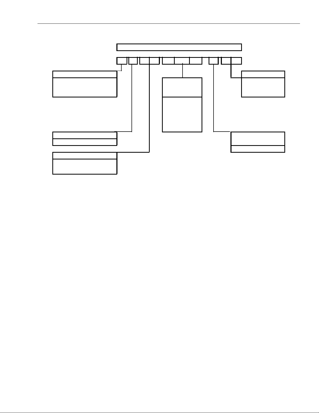
PRODUCT NOMENCL ATURE
D3HH 0 6 0 A 46
PRODUCT CATEGORY VOLTAGE CODE
D = Single Package Air
Conditioner
(Air Cooled)
PRODUCT GENERATION
Number = Generation
PRODUCT IDENTIFIER
SK = Vertical Indoor Packaged Unit
HH = Horizontal Indoor Packaged
Unit
NOMINAL
COOLING
CAPACITY (MBH)
024 = 24,000 BTUH
036 = 36,000BTUH
048 = 48,000BTUH
060 = 60,000BTUH
096 = 96,000BTUH
120=120,000BTUH
144=144,000BTUH
180 = 080,000 BTUH
06 = 208/230-1-60
25 = 208/230-3-60
46 = 460-3-60
58 = 575-3-60
FACTORY INSTALLED
ELECTRIC HEAT
A = No Electric Heat Installed
GENERAL MECHANICAL SPECIFICATIONS
GENERAL
charge. The 12 and 15 ton models are shipped as separate
evaporator and condensing unit modules (nitrogen holding
charge only). The 4 through 10 ton units include refrigeration
line shut-off valves to allow the units to be field split. All packages/models are designed for suspended mounting via integral structural channels .
CABINET
Gauge corrosion resistant "Galvalume" coated steel. The
entire unit interior (both evaporator and condensing section)
is insulated with 1/2" thick 2 LB density insulation. Service
panels are equipped with 1/2" thick 2 lb. density insulation.
Service panels are equipped with lifting handles for ease of
removal and handling.
COMPRESSORS
compressors. Compressors are mounted on rubber isola tors
to minimize v ibration trans mission. Inte rnal overload pr otection is provided. Extern al h igh pr es su re an d lo w pr es su re c utout switches are included in each compressor control circuit.
Crankcase heaters are standard on all models.
REFRIGERANT CIRCUIT
refrigeration circu it. The 8 to 15 to n units featu re two ind ependent refrigeration circuits. Each circuit includes an adjustable
thermal expansion valve (with external equalizer), liquid line
filter drie r, sight glass/ moisture indicato r, and service ga uge
ports.
EVAPORATOR AND CONDENSER COILS
and condenser coils are constructed of internally enhanced
- All 2 to 10 ton models ship with a full refrigerant
- All cabinets are completely constructed of 18
- All models utilize "Scroll" type hermetic
- The 2 to 5 tons units use a singl e
- The evaporator
copper tubes mechanically bonded to rippled aluminum plate
fins. Both coils are em plo ye d in a dra w -thro ugh co nfig uration.
Large evaporator coil face area minimizes potential water
blow-off (max face velocity is 550 fpm at rated airflow).
INDOOR/OUTDOOR FANS
- Forward curved, double inlet
and double width centrifugal blowers are used for both evaporator and condenser air movement. blow wheels are fabricated of galvanized steel. Blowers employ solid steel shafts,
supported in permanently lubricated ball bearing. All blowers are belt driven in permanently lubricated ball bearing. All
blowers are belt driven. Variable-pitch motor sheaves allow
for field adjustment of blower rpm.
ELECTRICAL/CONTROLS
- All units are comp letely fact ory
wired with all necessary controls. Manual reset protection is
provided on both evaporator and condenser motors. A manual reset circuit is also provided on each compressor control
circuit in the event of high/low pressure cutout. A 24 volt control circuit with oversize transformer, is provided for field connection.
FILTERS
- All models are shipped with 2 inch thick mediumefficiency throwaway filters factory installed. Filter rack is
internal to the cabinet.
FACTORY INSTALLED ACCESSORIES
OVERSIZED EVAPORATOR FAN MOTORS
horsepower motors and drive components are available for
those applications where external static pressure requirements exceed the capability of the standard motor.
- Increased
Unitary Products Group 3
Page 4
036-21187-001 REV A (0301)
CORROSION RESISTANT COATINGS - Condenser an d/or
evaporator coils shall have a 2 to 3 mil coating of Heresite P413 protective coating applied in a multiple dip and bake pro-
airflow conditions. The use of the field installed Low Ambient
Control is strongly recommended when hot gas bypass is
installed.
cess.
STAINLESS STEEL DRAIN PAN - Evaporator drain pan
shall be fabricated of 304 stainless steel material. The 3/4 in.
NPT drain connection fitting is also of 304 stainless steel.
HOT GAS BYPASS - Adjustable hot gas regulator and all
necessary piping shall be installed on lead compressor circuit. Bypass capacity shall be minimum 50% of compressor
capacity. The bypass valve opens at a preset suction pres-
FIELD INSTALLED ACCESSORIES
LOW AMBIENT CONTROL - Head pressure control damper
kit will allow unit operation down to 0°F ambient. Damper
assembly fits over condenser air intake. The kit includes
damper actuator, and low pressure switch bypass timer(s).
sure to prevent coil freeze-up at light evaporator load, or low
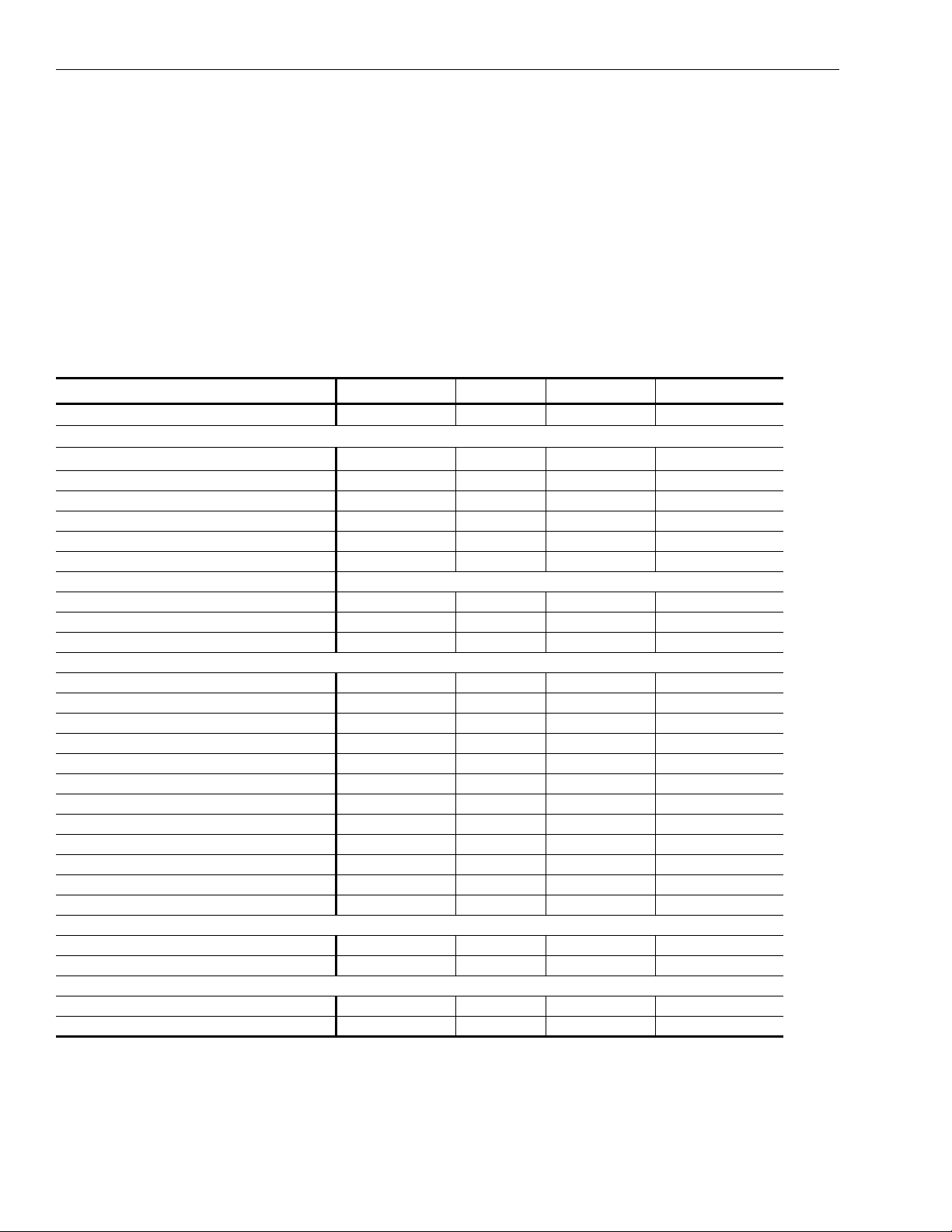
TABLE 1: GENERAL DATA 2 TO 5 TONS
MODEL DHH
NOMINAL COOLING (TONS) 2 3 4 5
CALCULATED SEER
GROSS COOLING CAPACITY (BTUH) 26600 37200 50300 62700
DESIGN CFM 800 1200 1600 2000
SYSTEM POWER (KW) 2.52 3.85 4.88 6.24
COMPRESSOR-TYPE SCROLL SCROLL SCROLL SCROLL
NUMBER USED 1 1 1 1
EVAPORATOR COIL-TYPE "COPPER TUBES, ALUMINUM FINS"
FACE AREA (SQ FT) 2.44 3.00 4.17 5.14
ROWS/FPI 3/12 3/14 3/14 3/14
REFRIGERANT CONTROL TX VALVE TX VALVE TX VALVE TX VALVE
CONDENSER COIL-TYPE "COPPER TUBES, ALUMINUM FINS"
FACE AREA (SQ FT) 3.75 3.75 6.67 6.67
ROWS/FPI 4/16 4/16 4/14 4/14
EVAPORATOR FAN-TYPE
NUMBER USED 1 1 1 1
DIAMETER x WIDTH (IN) 9x7 10x8 12x9 12x9
DRIVE
MOTOR HP (STANDARD/OVERSIZED) 0.25/0.5 0.5/0.75 0.5/0.75 0.75/1
CONDENSER FAN-TYPE
NUMBER USED 1 1 1 1
DIAMETER x WIDTH (IN) 10x10 10x10 12x11 12x11
DRIVE
MOTOR HP (STANDARD) 0.5 1 1 2
NUMBER USED-SIZE (IN) 1-18x24x2 1-18x25x2 2-16x20x2 2-20x20x2
CONDENSATE CONNECTION
WEIGHT
OPERATING 490 520 765 785
SHIPPING 535 565 820 840
*. Per ARI Standards 210
*
:
024 036 048 060
COOLING PERFORMANCE
10.5 10.5 10.6 10.4
FILTERS
4 Unitary Products Group
Page 5
036-21187-001 REV A (0301)
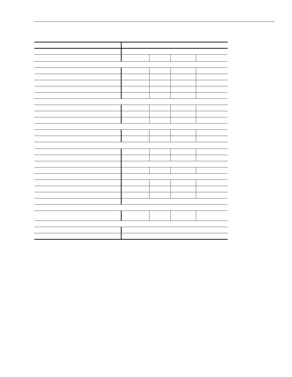
TABLE 2: GENERAL DATA 8 TO 15 TONS
MODEL DHH: 096 120 144 180
NOMINAL COOLING (TONS) 8 10 12 15
CALCULATED EER
GROSS COOLING CAPACITY (BTUH) 100500 124400 154200 191600
DESIGN CFM 3000 3800 4600 5600
SYSTEM POWER (KW) 10.22 13.35 17.11 24.20
COMPRESSOR-TYPE SCROLL SCROLL SCROLL SCROLL
NUMBER USED 2 2 2 2
EVAPORATOR COIL-TYPE COPPER TUBES, ALUMINUM FINS"
FACE AREA (SQ FT) 6.86 7.99 9.72 10.89
ROWS/FPI 4/12 4/14 4/12 4/12
REFRIGERANT CONTROL TX VALVE TX VALVE TX VALVE TX VALVE
CONDENSER COIL-TYPE COPPER TUBES, ALUMINUM FINS
FACE AREA (SQ FT) 9.03 9.03 14.00 14.00
ROWS/FPI 5/16 5/16 6/14 6/14
EVAPORATOR FAN-TYPE
NUMBER USED 1 1 1 1
DIAMETER x WIDTH (IN) 15 x 11 15 x 11 15 x 15 15 x 15
DRIVE BELT
MOTOR HP (STANDARD/OVERSIZED) 1.5/2 3/NA 3/5 5/NA
CONDENSER FAN-TYPE "CENTRIFUGAL, FORWARD CURVED"
NUMBER USED 1 1 1 1
DIAMETER x WIDTH (IN) 15 x 15 15 x 15 15 x 15 15 x 15
DRIVE
MOTOR HP (STANDARD) 3 5 5 7.5
NUMBER USED-SIZE (IN) 2-20 x 25 x 2
CONDENSATE CONNECTION 3/4 NPT
OPERATING 1220 1260 1625 1785
SHIPPING 1305 1330 1780 1940
*
*. PER ARI STANDARDS 360
9.4 8.8 8.6 7.4
COOLING PERFOMANCE
"CENTRIFUGAL, FORWARD CURVED"
FILTERS
3-16 x 25 x
2
4-14 x 20 x 2 6-14 x 20 x 2
Unitary Products Group 5
Page 6

036-21187-001 REV A (0301)
TABLE 3: COOLING PERFORMANCE DATA - DHH024
AMBIENT CONDENSER AIR TEMPERATURE
DHH024
2 TON
62°F67°F72°F62°F67°F72°F62°F67°F72°F62°F67°F72°F
CFM EDB TC SC TC SC TC SC TC SC TC SC TC SC TC SC TC SC TC SC TC SC TC SC TC SC
75°F 24.7 17.8 27.1 14.3 29.6 10.8 23.8 17.3 26.1 13.7 28.5 10.5 22.8 16.6 25.0 13.5 27.2 10.0 21.7 16.2 23.6 12.9 25.0 9.1
700 80°F 24.7 20.9 27.1 17.4 29.6 14.0 23.8 20.4 26.1 17.0 28.5 13.6 22.8 19.9 25.0 16.7 27.2 13.1 21.7 19.4 23.6 16.0 25.0 11.6
85°F 24.7 24.0 27.1 20.5 29.6 17.1 23.8 23.5 26.1 20.2 28.5 16.7 23.1 23.1 25.0 19.8 27.2 16.2 22.2 22.2 23.6 19.2 25.0 14.1
75°F 25.4 18.9 27.7 15.0 30.2 11.1 24.4 18.3 26.6 14.4 29.2 10.7 23.4 17.8 25.5 14.1 27.8 10.2 22.3 17.4 24.1 13.4 25.7 9.4
800 80°F 25.4 22.3 27.7 18.5 30.2 14.5 24.4 21.8 26.6 18.0 29.2 14.2 23.4 21.4 25.5 17.6 27.8 13.7 22.3 20.9 24.1 17.1 25.7 12.1
85°F 25.7 25.7 27.7 21.9 30.2 18.0 25.1 25.1 26.6 21.6 29.2 17.7 24.2 24.2 25.5 21.1 27.8 17.2 23.0 23.0 24.1 20.6 25.7 14.6
75°F 25.9 19.8 28.3 15.6 30.8 11.3 24.9 19.3 27.2 15.2 29.7 10.9 23.8 18.8 26.0 14.8 28.3 10.4 22.5 18.3 24.5 14.2 26.2 9.6
900 80°F 25.9 23.6 28.3 19.5 30.8 15.1 24.9 23.1 27.2 19.1 29.7 14.7 23.8 22.7 26.0 18.6 28.3 14.2 22.5 22.1 24.5 18.1 26.2 12.5
85°F 26.6 26.6 28.3 23.3 30.8 19.0 25.7 25.7 27.2 23.0 29.7 18.6 25.0 25.0 26.0 22.5 28.3 18.1 23.9 23.9 24.5 22.0 26.2 15.5
85°F95°F105°F115°F
EWB EWB EWB EWB
TABLE 4: COOLING PERFORMANCE DATA - DHH036
AMBIENT CONDENSER AIR TEMPERATURE
DHH036
3 TON
62°F67°F
CFM EDB TC SC TC SC TC SC TC SC TC SC TC SC TC SC TC SC TC SC TC SC TC SC TC SC
75°F 34.5 25.6 38.2 20.7 40.9 15.1 33.2 24.9 36.2 19.6 39.2 14.5 31.9 24.2 34.8 19.0 37.8 14.1 30.5 23.3 33.3 18.5 36.1 13.2
1000
80°F 34.5 30.1 38.2 25.5 40.9 19.7 33.2 29.5 36.2 24.2 39.2 19.1 31.9 28.8 34.8 23.6 37.8 18.7 30.5 27.8 33.3 23.1 36.1 16.9
85°F 34.5 34.5 38.2 30.4 40.9 24.2 33.8 33.8 36.2 28.8 39.2 23.7 32.7 32.7 34.8 28.3 37.8 23.3 31.5 31.5 33.3 27.7 36.1 20.6
75°F 35.6 27.6 39.1 21.9 42.0 15.7 34.2 27.2 37.2 20.9 40.2 15.1 32.8 26.3 35.7 20.3 38.7 14.7 31.3 25.6 34.1 19.7 37.0 13.5
1200
80°F 35.6 33.0 39.1 27.5 42.0 21.0 34.2 32.7 37.2 26.3 40.2 20.4 32.8 31.6 35.7 25.7 38.7 20.0 31.3 30.9 34.1 25.1 37.0 17.7
85°F 37.0 37.0 39.1 33.1 42.0 26.3 35.8 35.8 37.2 31.6 40.2 25.7 34.4 34.4 35.7 31.1 38.7 25.2 33.1 33.1 34.1 30.4 37.0 22.0
75°F 36.4 29.6 39.8 23.2 42.9 16.2 34.9 28.9 37.9 22.2 41.0 15.7 33.5 28.3 36.4 21.7 39.5 15.2 31.8 27.6 34.7 21.1 37.8 13.8
1400
80°F 36.4 35.7 39.8 29.5 42.9 22.2 34.9 34.9 37.9 28.3 41.0 21.6 33.5 33.5 36.4 27.8 39.5 21.2 31.8 31.8 34.7 27.2 37.8 18.6
85°F 38.4 38.4 39.8 35.9 42.9 28.3 37.1 37.1 37.9 34.4 41.0 27.7 35.7 35.7 36.4 34.0 39.5 27.2 33.8 33.8 34.7 33.3 37.8 23.4
85°F95°F
EWB EWB EWB
72°F
62°F67°F72°F62°F67°F72°F
105°F
62°F
115°F
EWB
67°F72°F
TABLE 5: COOLING PERFORMANCE DATA - DHH048
AMBIENT CONDENSER AIR TEMPERATURE
DHH048
4 TON
62°F67°F72°F62°F67°F72°F62°F67°F72°F62°F67°F72°F
CFM EDB TC SC TC SC TC SC TC SC TC SC TC SC TC SC TC SC TC SC TC SC TC SC TC SC
75°F 47.5 35.8 51.6 28.0 56.0 20.7 45.8 35.0 49.6 27.3 53.8 20.1 43.2 33.6 47.4 26.4 51.6 19.5 41.8 33.1 45.3 25.6 48.6 18.3
1450
80°F 47.5 42.4 51.6 34.6 56.0 27.3 45.8 41.6 49.6 33.9 53.8 26.7 43.2 40.1 47.4 33.0 51.6 26.0 41.8 39.7 45.3 32.2 48.6 24.4
85°F 48.4 48.4 51.6 41.3 56.0 33.9 46.9 46.9 49.6 40.6 53.8 33.3 45.1 45.1 47.4 39.7 51.6 32.6 43.4 43.4 45.3 38.9 48.6 30.6
75°F 48.2 37.3 52.4 29.1 56.9 21.2 46.4 36.4 50.3 28.3 54.6 20.7 44.2 35.4 48.1 27.5 52.4 20.0 42.2 34.5 45.9 26.6 49.4 18.8
1600
80°F 48.2 44.4 52.4 36.3 56.9 28.4 46.4 43.6 50.3 35.5 54.6 28.0 44.2 42.6 48.1 34.7 52.4 27.1 42.2 41.8 45.9 33.8 49.4 25.5
85°F 49.8 49.8 52.4 43.6 56.9 35.6 48.2 48.2 50.3 42.7 54.6 35.3 46.4 46.4 48.1 41.9 52.4 34.3 44.6 44.6 45.9 41.0 49.4 32.3
75°F 49.0 39.1 53.2 30.2 57.8 21.7 47.1 38.2 51.1 29.5 55.4 21.1 44.8 37.2 48.8 28.6 53.2 20.5 42.8 36.3 46.6 27.9 50.4 19.6
1800
80°F 49.0 47.0 53.2 38.1 57.8 29.6 47.1 46.2 51.1 37.4 55.4 28.8 44.8 44.8 48.8 36.5 53.2 28.3 42.8 42.8 46.6 35.8 50.4 27.1
85°F 51.2 51.2 53.2 46.1 57.8 37.5 49.7 49.7 51.1 45.3 55.4 36.7 47.6 47.6 48.8 44.4 53.2 36.1 46.0 46.0 46.6 43.8 50.4 34.7
6 Unitary Products Group
85°F95°F105°F115°F
EWB EWB EWB EWB
Page 7

036-21187-001 REV A (0301)
TABLE 6: COOLING PERFORMANCE DATA - DHH060
AMBIENT CONDENSER AIR TEMPERATURE
DHH060
5 TON
62°F67°F72°F62°F67°F72°F62°F67°F72°F62°F67°F72°F
CFM EDB TC SC TC SC TC SC TC SC TC SC TC SC TC SC TC SC TC SC TC SC TC SC TC SC
75°F 58.8 44.3 63.8 34.7 69.2 25.7 56.6 43.2 61.4 33.8 66.6 24.9 54.1 42.0 58.8 32.8 63.8 24.1 51.6 40.8 56.1 31.7 61.0 23.3
1800
80°F 58.8 52.5 63.8 42.8 69.2 33.9 56.6 51.4 61.4 42.0 66.6 33.1 54.1 50.3 58.8 41.0 63.8 32.2 51.6 49.1 56.1 39.9 61.0 31.4
85°F 59.8 59.8 63.8 51.1 69.2 42.0 58.0 58.0 61.4 50.2 66.6 41.2 56.0 56.0 58.8 49.2 63.8 40.3 53.9 53.9 56.1 48.1 61.0 39.5
75°F 59.8 46.4 64.8 36.0 70.3 26.3 57.5 45.2 62.4 35.1 67.6 25.6 54.7 43.8 59.6 34.0 64.8 24.7 52.3 42.8 56.8 33.0 61.9 23.7
2000
80°F 59.8 55.3 64.8 44.9 70.3 35.2 57.5 54.2 62.4 44.1 67.6 34.6 54.7 52.7 59.6 43.0 64.8 33.6 52.3 51.8 56.8 42.0 61.9 32.7
85°F 61.7 61.7 64.8 53.9 70.3 44.1 59.8 59.8 62.4 53.2 67.6 43.8 57.6 57.6 59.6 52.0 64.8 42.5 55.4 55.4 56.8 50.9 61.9 41.5
75°F 60.6 48.3 65.6 37.5 71.2 26.8 58.2 47.2 63.1 36.4 68.4 26.1 55.6 45.9 60.4 35.4 65.6 25.3 53.0 44.9 57.5 34.4 62.6 24.5
2200
80°F 60.6 58.0 65.6 47.5 71.2 36.4 58.2 56.9 63.1 46.2 68.4 35.7 55.6 55.6 60.4 45.2 65.6 34.0 53.0 53.0 57.5 44.1 62.6 34.0
85°F 63.3 63.3 65.6 57.5 71.2 46.0 61.3 61.3 63.1 56.0 68.4 45.3 59.1 59.1 60.4 55.0 65.6 44.5 56.8 56.8 57.5 53.8 62.6 43.5
85°F95°F105°F115°F
EWB EWB EWB EWB
TABLE 7: COOLING PERFORMANCE DATA - DHH096
AMBIENT CONDENSER AIR TEMPERATURE
DHH096
8 TON
62°F67°F72°F62°F67°F72°F62°F67°F72°F62°F67°F72°F
CFM EDB TC SC TC SC TC SC TC SC TC SC TC SC TC SC TC SC TC SC TC SC TC SC TC SC
75°F 96.5 73.5 104.6 57.5 113.8 42.3 92.4 71.4 100.5 55.9 109.8 41.1 88.8 69.9 96.6 54.5 105.3 39.9 84.8 68.0 92.7 53.1 101.6 38.9
3000
80°F 96.5 87.3 104.6 71.4 113.8 58.1 92.4 85.2 100.5 69.9 109.8 54.9 88.8 83.9 96.6 68.4 105.3 53.4 84.8 82.0 92.7 66.9 101.6 52.4
85°F 98.7 98.7 104.6 85.3 113.8 69.8 95.4 95.4 100.5 83.9 109.8 68.6 92.4 92.4 96.6 82.3 105.3 67.2 89.2 89.2 92.7 80.8 101.6 66.1
75°F 97.4 75.5 105.6 58.9 114.9 42.9 93.3 73.8 101.6 57.4 110.8 41.7 89.4 71.8 97.5 55.8 106.2 40.5 85.6 70.2 93.5 54.5 102.5 39.5
3200
80°F 97.4 90.1 105.6 73.7 114.9 57.4 93.3 88.5 101.6 72.1 110.8 56.2 89.4 86.6 97.5 70.5 106.2 54.9 85.6 85.0 93.5 69.0 102.5 53.8
85°F 100.6 100.6 105.6 88.3 114.9 71.9 96.2 96.2 101.6 86.9 110.8 70.8 94.1 94.1 97.5 85.3 106.2 69.4 90.8 90.8 93.5 83.7 102.5 68.3
75°F 98.2 77.6 106.5 66.2 115.9 43.5 94.1 75.7 103.0 59.1 111.8 42.3 90.2 74.0 98.3 57.3 107.1 41.1 86.2 72.9 94.3 56.0 103.4 40.1
3400
80°F 98.2 93.0 106.5 75.8 115.9 58.7 94.1 91.2 103.0 74.7 111.8 57.6 90.2 89.5 98.3 72.8 107.1 56.2 86.2 86.2 94.3 71.4 103.4 55.2
85°F 102.3 102.3 106.5 91.2 115.9 74.0 98.8 98.8 103.0 90.4 111.8 73.0 95.7 95.7 98.3 88.3 107.1 71.4 92.4 92.4 94.3 86.9 103.4 70.4
85°F95°F105°F115°F
EWB EWB EWB EWB
TABLE 8: COOLING PERFORMANCE DATA - DHH120
AMBIENT CONDENSER AIR TEMPERATURE
DHH120
10 TON
62°F67°F72°F62°F67°F72°F62°F67°F72°F62°F67°F72°F
CFM EDB TC SC TC SC TC SC TC SC TC SC TC SC TC SC TC SC TC SC TC SC TC SC TC SC
75°F 118.4 90.9 128.5 71.3 139.8 52.5 113.8 87.8 123.8 69.5 134.2 50.8 108.8 86.4 118.0 87.3 128.6 49.2 103.5 84.1 112.8 65.5 123.5 47.9
3600
80°F 118.4 108.0 128.5 88.6 139.8 69.7 113.8 104.8 123.8 87.0 134.2 67.9 108.8 103.9 118.0 84.7 128.6 56.2 103.5 101.5 112.8 82.9 123.5 64.8
85°F 121.8 121.8 128.5 106.0 139.8 86.9 118.0 118.0 123.8 104.3 134.2 85.0 113.8 113.8 118.0 101.9 128.6 83.3 103.5 109.6 112.8 100.2 123.5 81.8
75°F 120.2 95.3 130.5 74.2 141.8 53.7 115.4 53.7 125.6 72.4 136.2 52.1 110.3 90.9 119.8 70.4 130.5 50.5 105.0 88.7 114.5 68.7 125.2 49.2
4000
80°F 120.2 114.1 130.5 93.3 141.8 72.4 115.4 112.2 125.6 91.5 136.2 70.8 110.3 109.9 119.8 89.6 130.5 69.0 105.0 105.0 114.5 87.7 123.5 67.7
85°F 125.6 125.6 130.5 112.3 141.8 91.3 121.8 121.8 125.6 110.6 136.2 89.4 117.2 117.2 119.8 108.6 130.5 87.8 112.8 112.8 114.5 106.8 125.2 86.3
75°F 121.8 99.8 132.1 77.1 143.6 54.8 117.0 97.8 127.2 75.4 137.8 53.3 111 .6 95.7 121.2 73.4 132.0 51.7 106.2 93.3 115.8 71.5 126.6 50.3
4400
80°F 121.8 120.7 132.1 97.8 143.6 75.1 117.0 117.0 127.2 96.1 137.8 73.5 116.6 116.6 121.2 94.1 132.0 71.9 106.2 106.2 115.8 92.1 126.6 70.5
85°F 129.0 129.0 132.1 118.6 143.6 95.6 125.0 125.0 127.2 116.8 137.8 93.9 122.2 122.2 121.2 115.0 132.0 92.2 115.8 115.8 115.8 112.9 126.6 90.7
85°F95°F105°F115°F
EWB EWB EWB EWB
Unitary Products Group 7
Page 8

036-21187-001 REV A (0301)
TABLE 9: COOLING PERFORMANCE DATA - DHH144
AMBIENT CONDENSER AIR TEMPERATURE
DHH144
12 TON
62°F67°F72°F62°F67°F72°F62°F67°F72°F62°F67°F72°F
CFM EDB TC SC TC SC TC SC TC SC TC SC TC SC TC SC TC SC TC SC TC SC TC SC TC SC
75°F 146.0 109.2 158.6 85.9 172.0 63.4 140.8 106.5 152.5 83.5 163.6 60.3 134.6 103.5 146.4 81.1 159.6 59.6 128.2 100.5 139.6 78.5 152.4 57.4
4300
80°F 146.0 128.9 158.6 105.6 172.0 83.4 140.8 126.2 152.5 103.5 163.5 79.3 134.6 123.2 146.4 101.0 159.6 79.3 128.2 120.3 139.6 98.5 152.4 77.1
85°F 147.8 147.8 158.6 125.9 172.0 103.2 143.4 143.4 152.5 123.5 163.6 98.1 134.6 138.6 146.4 120.9 159.6 99.1 133.2 133.2 139.6 118.3 152.4 96.7
75°F 148.6 114.2 161.4 89.4 174.8 64.8 143.0 111.6 155.0 86.9 166.2 61.6 136.8 109.0 148.8 84.6 162.2 51.1 130.2 105.8 141.7 81.7 154.8 58.9
4800
80°F 148.6 135.9 161.4 111.3 174.8 86.5 143.0 133.4 155.0 108.9 166.2 57.5 136.8 130.9 148.8 106.5 162.2 82.8 130.2 127.7 141.7 103.5 154.8 80.4
85°F 152.8 152.8 161.4 133.3 174.8 108.3 148.0 148.0 155.0 130.9 166.2 103.0 143.0 143.0 148.8 128.5 162.2 104.6 137.4 137.4 141.7 125.4 154.8 102.0
75°F 150.8 119.4 163.6 92.4 177.2 66.0 145.0 116.7 157.0 90.1 168.4 62.8 138.6 113.7 150.6 87.7 164.4 62.3 132.6 11 1.6 143.5 85.3 156.8 60.8
5300
80°F 150.8 143.2 163.6 116.4 177.2 89.6 145.0 140.6 157.0 114.1 168.4 85.2 138.6 137.6 150.6 111.5 164.4 85.6 132.6 132.6 143.5 109.2 156.8 84.3
85°F 157.2 157.2 163.6 140.3 177.2 113.4 152.0 152.0 157.0 138.1 168.4 107.7 146.8 146.8 150.6 135.3 164.4 109.1 141.2 141.2 143.5 133.0 156.8 108.3
85°F95°F 105°F115°F
EWB EWB EWB EWB
TABLE 10: COOLING PERFORMANCE DATA - DHH180
AMBIENT CONDENSER AIR TEMPERATURE
DHH180
15TON
62°F67°F72°F62°F67°F72°F62°F67°F72°F62°F67°F72°F
CFM EDB TC SC TC SC TC SC TC SC TC SC TC SC TC SC TC SC TC SC TC SC TC SC TC SC
75°F 182.8 137.2 199.0 107.6 215.8 78.9 175.6 132.7 190.6 104.2 207.6 76.3 168.0 128.8 182.0 100.8 197.8 73.1 159.0 124.6 173.2 97.3 189.1 70.5
5400
80°F 182.8 161.9 199.0 132.3 215.8 103.5 175.6 156.9 190.6 129.0 207.6 100.8 168.0 153.3 182.0 125.3 197.8 97.5 159.0 149.3 173.2 121.9 189.1 94.9
85°F 184.4 184.4 199.0 157.0 215.8 128.1 178.8 178.8 190.6 153.8 207.6 125.3 172.5 172.5 182.0 150.1 197.8 122.0 165.2 165.2 173.2 146.7 189.1 119.3
75°F 186.0 143.5 202.2 111.4 219.2 80.4 178.4 138.6 193.6 108.0 210.8 77.7 170.6 135.2 184.6 104.4 200.4 74.5 161.4 131.0 175.6 101.1 192.0 72.1
6000
80°F 186.0 170.9 202.2 138.5 219.2 107.1 178.4 165.3 193.6 135.1 210.8 104.5 170.6 162.2 184.6 131.6 200.4 101.2 161.4 158.0 175.6 128.1 192.0 98.8
85°F 190.8 190.8 202.2 165.5 219.2 134.1 184.0 184.0 193.6 162.2 210.8 131.5 177.6 177.6 184.6 158.7 200.4 128.0 170.2 170.2 175.6 155.4 192.0 125.5
75°F 188.6 148.6 205.5 115.4 222.4 81.8 180.8 144.6 196.2 111.6 213.6 79.0 172.8 141.1 187.0 108.2 203.0 76.1 163.4 137.4 177.8 105.0 194.4 73.6
6600
80°F 188.6 177.8 205.5 145.2 222.4 110.9 180.8 173.9 196.2 141.0 213.6 108.2 172.8 170.5 187.0 137.8 203.0 105.1 163.4 163.4 177.8 134.5 194.4 102.2
85°F 195.6 195.6 205.5 174.8 222.4 140.3 189.2 189.2 196.2 170.4 213.6 137.5 182.0 182.0 187.0 167.1 203.0 133.9 174.6 174.6 177.8 164.1 194.4 131.2
85°F95°F 105°F115°F
EWB EWB EWB EWB
TABLE 11: SUPPLY AIR BLOWER PERFORMANCE 2 TO 5 TON
MODEL
DHH
024
036
048
060
NOTE:
1. At higher evaporator airflows, and wet bulb conditions condensate carry-over may occur. Adjust airflow downward as necessary
2. Values include pressure drop from wet coil and clean filters
3. Shaded ares indicate oversized motors are required
SUPPLY
CFM
700 708 0.09 845 0.13 991 0.17 1120 0.21 1240 0.25 1352 0.30 1456 0.36
800 763 0.12 901 0.15 1016 0.20 1136 0.25 1251 0.30 1362 0.35 1489 0.41
900 830 0.16 955 0.20 1078 0.25 1192 0.30 1300 0.35 1401 0.40 1495 0.46
1000 779 0.18 880 0.23 978 0.28 1074 0.34 1167 0.40 1256 0.47 1342 0.54
1200 890 0.29 985 0.34 1075 0.40 1159 0.47 1239 0.54 1314 0.62 1382 0.71
1400 1007 0.43 1090 0.50 1169 0.57 1244 0.64 1315 0.70 1382 0.77 - 1450 664 0.27 742 0.33 819 0.39 895 0.46 970 0.53 1043 0.61 1116 0.69
1600 710 0.34 791 0.41 867 0.48 938 0.56 1005 0.63 1066 0.70 1123 0.77
1800 780 0.47 853 0.54 920 0.61 983 0.68 1040 0.75 - - - 1800 696 0.39 776 0.46 850 0.54 921 0.62 988 0.69 1051 0.78 1110 0.86
2000 752 0.51 826 0.59 895 0.67 960 0.76 1021 0.86 1077 0.96 1129 1.07
2200 812 0.66 881 0.75 946 0.84 1007 0.93 1065 1.02 - - - -
0.2 0.4 0.6 0.8 1.0 1.2 1.4
RPM BPH RPM BPH RPM BPH RPM BPH RPM BPH RPM BPH RPM BPH
EXTERNAL STATIC PRESSURE - INCHES W. C.
8 Unitary Products Group
Page 9

036-21187-001 REV A (0301)
TABLE 12: SUPPLY AIR BLOWER PERFORMANCE 8 TO 15 TON
EXTERMAL STATIC PRESSURE - INCHES W.C.
MODEL
DHH
096
120
144
180
NOTE:
1. At higher evaporator airflows, and wet bulb conditions condensate carry-over may occur. Adjust airflow downward as necessary
2. Values include pressure drop from wet coil and clean filters
3. Shaded ares indicate oversized motors are required
SUPPLY CFM
3000 640 0.77 700 0.88 757 1.01 810 1.14 861 1.26 908 1.36 854 1.58 995 1.65 1088 1.80
3200 676 0.92 733 1.06 787 1.18 888 1.31 887 1.44 8.84 1.59 979 1.71 1020 1.95 1059 1.96
3400 710 1.08 764 1.22 816 1.38 885 1.48 812 1.64 858 1.78 1001 1.82 1043 2.07 - 3600 758 1.30 807 1.44 858 1.58 903 1.78 848 1.88 992 2.08 1034 2.18 1074 2.34 1118 2.48
4000 830 1.75 876 1.80 822 2.07 965 2.23 1007 2.38 1048 2.58 1087 2.72 1128 2.88 1168 3.05
4400 9102.318522.498842.0010842.8410783.02-------4300 688 1.31 745 1.48 788 1.65 847 1.83 885 2.02 841 2.21 888 2.40 1030 2.60 1075 2.80
4800 757 1.77 808 1.99 857 2.16 808 2.35 847 2.55 990 2.78 1031 2.97 1078 3.19 1133 3.41
5300 828 2.84 878 2.55 818 2.76 861 2.98 1002 3.20 1042 3.42 1081 3.64 1119 3.37 1157 4.11
5400 817 2.87 884 2.58 909 2.79 858 3.01 884 3.28 1034 3.45 1078 3.63 1111 3.91 1148 4.15
6000 888 3.20 842 3.43 983 3.67 1028 3.91 1062 4.15 1099 4.40 1136 4.94 1171 4.89 - 6600 8784.2010184.4510574.7110844.98----------
0.20.40.60.81.01.21.41.61.8
RPM BPH RPM BPH RPM BPH RPM BPH RPM BPH RPM BPH RPM BPH RPM BHP RPM BHP
TABLE 13: CONDENSER AIR BLOWER PERFORMANCE 2 TO 5 TON
MODEL
DHH
024 1400 731 0.23 842 0.29 946 0.36 1043 0.43 1133 0.50 - 036 1950 941 0.54 1024 0.62 1104 0.71 1182 0.80 1258 0.89 1320 1.05
048 2550 669 0.58 743 0.68 816 0.79 887 0.90 956 1.02 - 060 3300 826 1.17 885 1.30 942 1.42 999 1.56 1056 1.70 1112 1.85
OUTDOOR
CFM
0.20.40.60.81.01.2
RPM BPH RPM BPH RPM BPH RPM BPH RPM BPH RPM BPH
EXTERNAL STATIC PRESSURE - INCHES W.C.
TABLE 14: CONDENSER AIR BLOWER PERFORMANCE 8 TO 15 TON
MODEL
DHH
096 4800 757 1.77 808 1.96 857 2.18 903 2.35 947 2.55 880 2.76 1031 2.97 1073 3.19
120 5700 801 2.88 845 3.20 986 3.43 1026 3.66 1085 3.90 1103 4.13 1133 4.87 1175 4.62
144 6800 811 3.41 848 3.62 889 3.35 930 4.09 971 4.35 1010 4.61 1046 4.87 1087 5.14
OUTDOOR CF M
0.20.40.60.81.01.21.41.8
RPM BPH RPM BPH RPM BPH RPM BPH RPM BPH RPM BPH RPM BHP RPM BHP
EXTERNAL STATIC PRESSURE - INCHES W.C.
Unitary Products Group 9
Page 10

036-21187-001 REV A (0301)
ELECTRICAL DATA
TABLE 15: STANDARD MOTORS - 2 TO 5 TON
MODEL
DHH
024A06 208-230/1/60 1 @ 13.6 61.0 0.25 3.0 0.50 4.8 24.80 35
024A25 208-230/3/60 1 @ 8.6 55.0 0 .25 1.8 0.50 2.4 14.95 20
036A06 208-230/1/60 1 @ 17.9 88.0 0.50 4.8 1.00 7.2 34.38 50
036A25 208-230/3/60 1 @ 11.4 77.0 0.50 2.4 1.00 3.7 20.35 30
036A46 460/3/60 1 @ 5.7 39.0 0.50 1.1 1.0 0 1. 7 9.93 15
036A58 575/3/60 1 @ 4.7 31.0 0.50 0.9 1.0 0 1. 5 8.28 15
048A06 208-230/1/60 1 @ 26.4 129.0 0.50 4.8 1.00 7.2 45.00 70
048A25 208-230/3/60 1 @ 15.0 99.0 0.50 2.4 1.00 3.7 24.85 35
048A46 460/3/60 1 @ 8.2 49.5 0.50 1.1 1.0 0 1.7 13.05 20
048A58 575/3/60 1 @ 6.4 40.0 0.50 0.9 1.0 0 1.5 10.40 15
060A25 208-230/3/60 1 @ 19.3 123.0 0.75 3.1 2.00 6.6 33.83 50
060A46 460/3/60 1 @ 10.0 62.0 0 .75 1.4 2.00 3.0 16.90 25
060A58 575/3/60 1 @ 7.9 50.0 0.75 1.1 2.0 0 2.5 13.48 20
VOLTAGE
COMPRESSOR EVAPORATOR FAN CONDENSER FAN MIN. CCT.
QTY RLA LRA HP FLA HP FLA
AMPACITY
MAX FUSE/
CCT. BKR. AMP
TABLE 16: STANDARD MOTORS - 8 TO 15 TONS
MODEL
DHH
096A25 208-230/3/60 2 @ 15.0 99.0 1.550 4.8 3.00 9.2 47.75 60
096A46 460/3/60 2 @ 8.2 49.5 1.50 2.2 3.00 4.2 24.85 30
096A58 575/3/60 2 @ 6.4 40.0 1.50 1.9 3.00 3.6 19.90 25
120A25 208-230/3/60 2 @ 19.3 123.0 3.00 9.2 5.00 14.3 66.93 80
120A46 460/3/60 2 @ 10.0 62.0 3.00 4.2 5.00 6.6 33.30 40
120A58 575/3/60 2 @ 7.9 50.0 3.00 3.6 5.00 5.7 27.08 30
144A25 208-230/3/60 2 @ 20.7 156.0 3.00 9.2 5.00 14.3 70.08 90
144A46 460/3/60 2 @ 10.0 70.0 3.00 4.2 5.00 6.6 33.30 40
144A58 575/3/60 2 @ 8.2 54.0 3.00 3.6 5.00 5.7 27.75 35
180A25 208-230/3/60 2 @ 32.1 195.0 5.00 14.3 7.50 21.8 108.33 125
180A46 460/3/60 2 @ 16.4 95.0 5.00 6.6 7.50 10.0 53.50 60
180A58 575/3/60 2 @ 12.0 80.0 5.00 5.7 7.50 8.4 41.10 50
VOLTAGE QTY
COMPRESSOR EVA PORATOR FAN CONDENSER FAN
RLA LRA HP FLA HP FLA
MIN. CCT.
AMPACITY
MAX FUSE/
CCT. BKR. AMP
10 Unitary Products Group
Page 11

036-21187-001 REV A (0301)
ELECTRICAL DATA
TABLE 17: OVERSIZE EVAPORATOR MOTORS - 2 TO 5 TONS
MODEL
DHH
024A06 208-230/1/60 1 @ 13.6 61.0 0.50 4.8 0.50 4.8 26.60 40
024A25 208-230/3/60 1 @ 8. 6 55.0 0.50 2.4 0.50 2.4 15.55 20
036A06 208-230/1/60 1 @ 17.9 88.0 0.75 5.9 1.00 7.2 35.48 50
036A25 208-230/3/60 1 @ 11.4 77.0 0.75 3.1 1.00 3.7 21.05 30
036A46 460/3/60 1 @ 5.7 39.0 0.75 1.4 1.00 1.7 10.23 15
036A58 575/3/60 1 @ 4.7 31.0 0.75 1.1 1.00 1.5 8.48 15
048A06 208-230/1/60 1 @ 26.4 129.0 0.75 5.9 1.00 7.2 46.10 70
048A25 208-230/3/60 1 @ 15.0 99.0 0.75 3.1 1.00 3.7 25.55 40
048A46 460/3/60 1 @ 8.2 49.5 0.75 1.4 1.00 1.7 13.35 20
048A58 575/3/60 1 @ 6.4 40.0 0.75 1.1 1.00 1.5 10.60 15
060A25 208-230/3/60 1 @ 19.3 123.0 1.00 3.7 2.00 6.6 34.43 50
060A46 460/3/60 1 @ 10.0 62.0 1.00 1.7 2.00 3.0 17.20 25
060A58 575/3/60 1 @ 7.9 50.0 1.00 1.5 2.00 2.5 13.88 20
VOLTAGE QTY
COMPRESSOR EVAPORATOR FAN CONDENSER FAN
RLA LRA RLA LRA RLA LRA
MIN. CCT.
AMPACITY
CCT. BKR. AMP
TABLE 18: OVERSIZE EVAPORATOR MOTORS - 8 TO 10 TON
MODEL DHH
096A25 208-230/3/60 2 @ 15.0 99.0 2.00 6.6 3.00 9.2 49.55 60
096A46 460/3/60 2 @ 8.2 49.5 2.00 3.0 3.00 4.2 25.65 30
096A58 575/3/60 2 @ 6.4 40.0 2.00 2.5 3.00 3.6 20.50 25
120A25 208-230/3/60 2 @ 19.3 123.0 3.00* 9.2 5.00 14.3 66.93 80
120A46 460/3/60 2 @ 10.0 62.0 3.00* 4.2 5.00 6.6 33.30 40
120A58 575/3/60 2 @ 7.9 50.0 3.00* 3.6 5.00 5.7 27.08 30
144A25 208-230/3/60 2 @ 20.7 156.0 5.00 14.3 5.00 14.3 75.18 90
144A46 460/3/60 2 @ 10.0 70.0 5.00 6.6 5.00 6.6 35.70 45
144A58 575/3/60 2 @ 8.2 54.0 5.00 5.7 5.00 5.7 29.85 35
180A25 208-230/3/60 2 @ 32.1 195.0 5.00* 14.3 7.50 21.8 108.33 125
180A46 460/3/60 2 @ 16.4 95.0 5.00* 6.6 7.50 10.0 53.50 60
180A58 575/3/60 2 @ 12.0 80.0 5.00* 5.7 7.50 8.4 41.10 50
VOLT AGE
COMPRESSOR EVAPORATOR FAN CONDENSER FAN
QTY
RLA LRA HP FLA HP FLA
MIN. CCT.
AMPACITY
MAX FUSE/
CCT. BKR. AMP
MAX FUSE/
Unitary Products Group 11
Page 12

036-21187-001 REV A (0301)
FIGURE 1: 2 TO 3 TON UNIT DIMENSIONS
12 Unitary Products Group
Page 13

036-21187-001 REV A (0301)
FIGURE 2: 4 TO 5 TON UNIT DIMENSIONS
Unitary Products Group 13
Page 14

036-21187-001 REV A (0301)
FIGURE 3: 8 TO 10 UNIT DIMENSIONS
14 Unitary Products Group
Page 15

036-21187-001 REV A (0301)
FIGURE 4: 12 TO 15 UNIT DIMENSIONS
Unitary Products Group 15
Page 16

Subject to change without notice. Printed in U.S.A. CD: 036-21187-001 REV A (0301)
Copyright © by Unitary Produc ts Group 2001. All rights reserved. Supersedes: 530.45-TGIY (600)
Unitary 5005 Norman
Products York OK
Group Drive 73069
 Loading...