

Page 1
530.26-TG3YI (1294)
®
SINGLE P ACKAGE
GAS / ELECTRIC UNITS AND
SINGLE P ACKAGE AIR CONDITIONERS
D3CE / D3CG 180 & 240
(WORLD 50 HZ)
DCG
Shown
DESCRIPTION
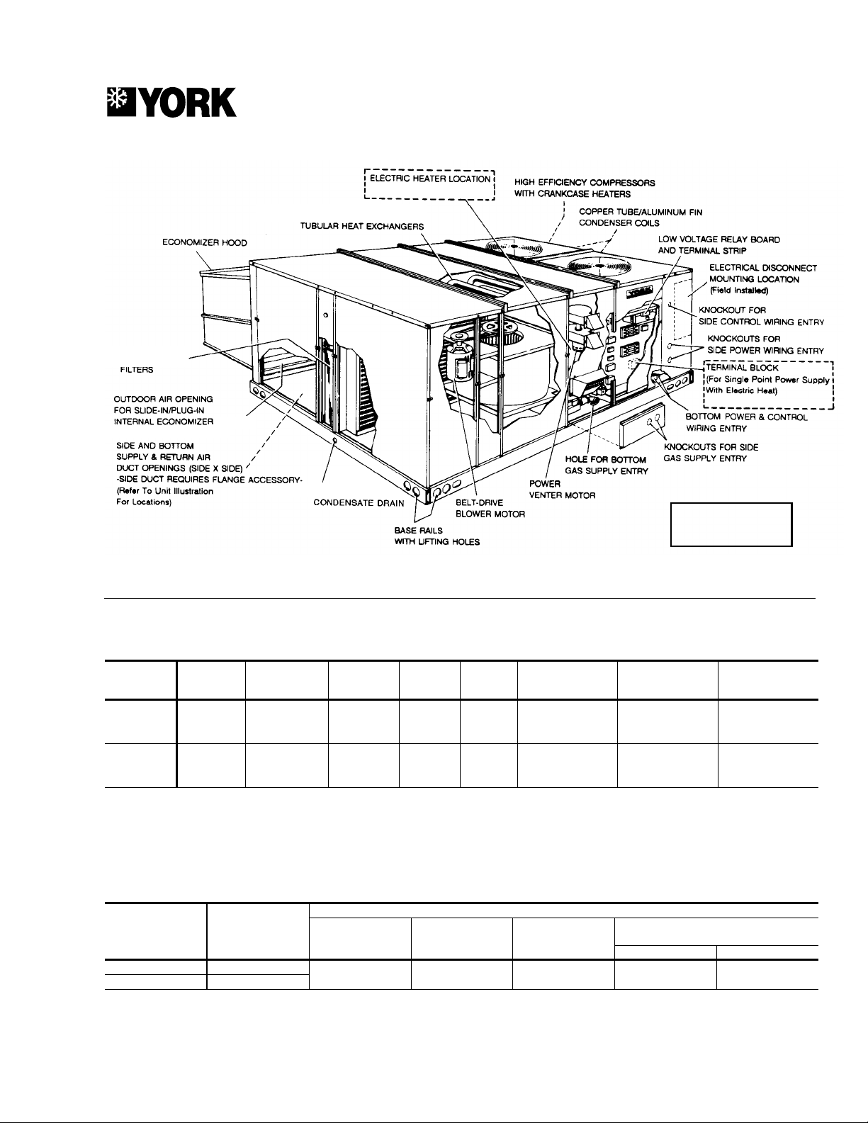
Sunline 2000 units are highly efficient, convertible rooftops. All
models have dual refrigerant circuits for efficient part load
operation. Although the units are primarily designed for curb
mounting on a roof, they can also be slab-mounted at ground
level or set on steel beams above a finished roof.
These units are designed and manufactured under ISO 9002
Quality System Certification.
Cooling only, cooling with gas heat and cooling with
supplemental electric heat units are available with a wide
variety of field-installed accessories to make them suitable for
almost every applicatio n.
All units are self-contained and assembled on full perimeter
base rails. The base rails have holes in the four corners for
overhead rigging.
Every unit is completely piped, wired, charged and tested at
the factory to simplify the field installation and to provide years
of dependable operation. Powder paint cabinets provide an
exceptionally durable finish with the 750 hour salt spray
process per ASTM-B117 test standard.
All models are available with three different outdoor air damper
accessosries:
• Single enthalpy economizer
• Differential enthalpy economizer
• Motorized outdoor air intake damper
All models (including those with an economizer ) are suitable
for either downflow or sideflow duct connections. For downflow
duct, remove the sheet metal panels from the supply and return
air openings through the base of the unit. For sideflow duct,
replace the supply and return air panels on the rear of the unit
with a side duct flange accessory.
A fixed outdoor air intake assembly is shipped in the return air
compartment of all units. The assembly includes a rain hood
with a damper that can be set for 10, 15 or 25% outdoor air.
With bottom duct connections, the intake damper assembly
should be mounted over the opening in the return air panel.
SUNLINE 2000
With horizontal ductwork, it should be mounted on the return
air duct.
All supply air blowers are equipped with a belt drive that can
be adjusted to meet the exact requirements of the job.
All compressors include crankcase heat and internal pressure
relief. Every refrigerant circuit includes an expansion valve, a
liquid line filte r-drier, a d ischarg e line high pre ssure s witch a nd
a suction line with a freezestat and low pressure switch. The
unit control circuit includes a 75 V A transf ormer, a 24-volt circuit
breaker and a relay board wi th two compressor lockout c ircuits,
a terminal strip for thermostat wiring, plus an additional set of
pin connectors to simplify the interface of additional field
controls.
All gas heat models are built with two heating sections for two
equal stages of capacity control. Each section includes a
durable heat exchanger with aluminized steel tubes, a
redundant gas valve, spark ignition, power venting, an ignition
module for 100% shut-off and all of the safety controls required
to meet the latest ANSI standards.
The gas supply piping can be routed into the heating
compartment through a hole in the base pan of the unit or
through a knockout in the piping panel on the front of the unit.
All electric heat models are wired for a single pow er source and
include a bank of nickel chromium elements mounted at the
discharge of the supply air blower to provide a high velocity and
uniform distribution of air across the heating elements. Every
element is fully protected against excessive current and
temperature by fuses and two thermal limit switches.
The power supply wiring can be routed into the control box
through a threaded pipe connection in the base pan of the unit
or through a knockout in the wiring panel on the front of the unit.
Page 2

530.26-TG3YI
FIELD-INST ALLED ACCESSORIES
SINGLE INPUT ELECTRONIC ENTHALPY ECONOMIZERS
Includes a slide-in / plug-in damper assembly with fully
modulating spring-return motor actuator capable of introducing
up to 100% outdoor air with nominal 1% leakage type dampers.
The enthalpy system contains one sensor that monitors the
outdoor air and determines when the air is cool enough and dry
enough to provide “free” cooling.
The rain hood is painted to match the basic unit and must be
field-assembled before installing.
On units built prior to January 1995 an accessory field harness
must be installed.
Power exhaust is not available as a field installed option.
DUAL INPUT ELECTRONIC ENTHALPY ECONOMIZERS
Includes a slide-in / plug-in damper assembly with fully
modulating spring-return motor actuator capable of introducing
up to 100% outdoor air with nominal 1% leakage type dampers.
This enthalpy system contains one sensor that monitors the
outdoor air and one sensor that monitors the return air. The
logic module compares the two values and modulates the
dampers, providing the ma ximum ef ficie ncy of the econom izer
system.
The rain hood is painted to match the basic unit and must be
field-assembled before installing.
On units built prior to January 1995 an accessory field harness
must be installed.
Power exhaust is not available as a field installed option.
MOTORIZ ED O UTDO OR A IR INTAKE DAMPER - Includes a
slide-in / plug-in damp e r with a 2-position, spring-return mo t o r
actuator which opens to a pre-set position whenever the supply
air blower is operating and drives fully clo sed when the blower
shuts down.
On units built prior to January 1995 an accessory field harness
must be installled.
Power exhaust is not available as a field installed option.
BAROMETRIC RELIEF DAMPER - This damper accessory
can be used to relieve internal air pressure on units with an
economizer. This accessory includes a rain hood, a bird screen
and a fully assembled damper. With bottom duct connections,
the damper should be mounted over the opening in the return
air panel. With horizontal ductwork, the accessory should be
mounted on the return air duct.
ROOF CURBS - Roof curbs, 356mm (14 in.) high, provide a
water-tight seal between the unit and the finished roof. These
full perimeter curbs meet the requirements of the National
Roofing Contractors Association (NRCA) and are shipped
knocked-down for field assembly . They’re designed to fit inside
the base rails of the unit and include both a wood nailing strip
and duct hanger supports.
SIDE DUCT FLANGES - Twenty-five mi llimeter (1 in .) flanges
replace the supply and return air panels on the rear of the unit
to accommodate horizontal duct connections. These flanges
can also be used individually for bottom supply/horizontal
return or horizontal supply/bottom return.
HIGH SPEED DRIVE - A sma ller b lo wer p ulle y, a larger motor
pulley (including a replacement belt) increase the speed of the
supply air blower for applications with a higher airflow and/or
static pressure requirement.
ANTI-RECYCLE TIMERS - Two solid st ate t ime rs preve nt t he
compressors from short-cycling. Once a compressor is
de-energized, it remains de-energized for approximately five
minutes.
LOW AMBIENT CONTROLS TO 18°C (0°F) - An
autotransformer and a thermostat maintain stable system
operation by reducing the speed of the #1 condenser fan motor
at low oudoor temperatures. The kit also includes a 1-phase
motor to replace the unit’s standard 3-phase condenser fan
motor. Standard units can operate down to 4 °C (25 °F).
TABLE OF CONTENTS
Description ...........................................................................1
Field-Installed Accessories...................................................2
Ratings .................................................................................3
Cooling Capacities ...............................................................4
Blower Performance.............................................................8
Blower Motor and Drive Data.............................................12
Static Resistances..............................................................10
Field Wiring ........................................................................13
2 Unitary Products Group
Electrical Data - Cooling and Gas Heat .............................13
Electrical Data - Units with Electric Heat............................14
Physical Data .....................................................................14
Unit Dimensions.................................................................15
Roof Curb Dimensions.......................................................18
Typical Applications............................................................18
Page 3
MODEL DCG
(Gas Heating)
THROWA W AY
(OPTION / ACCESSORY)
530.26-TG3YI
®
SUNLINE 2000
(OPTION / ACCESS.) DCE UNITS
ALUMINIZED STEEL
D*CG UNITS
FEMALE
RATINGS
CAPACITY RA TINGS - Cooling / Electric Heating
Model
Rating
Point
1
Total Output,
Mbh / kW
Total Input,
kW
COP
2
EER
Sensible Output,
3
Mbh / kW
Latent Output,
Mbh / kW
T1 159 / 46.6 18.2 2.60 8.80 132 / 38.7 26.9 / 7.9
D3CE180
T2 142 / 41.7 20.0 2.10 7.15 141 / 41.2 1.6 / 0.5 18, 36, 54, 72
T3 152 / 44.6 16.4 2.75 9.40 119 / 34.9 33.2 / 9.7
T1 210 / 61.5 24.8 2.50 8.50 176 / 51.5 34.0 / 10.0
D3CE240
1
T1 = Moderate Climates, T2 = Hot Climates, T3 = Cool Climates.
2
COP = Coefficient of Performance - total output kW divided by the total input kW.
3
EER = Energy Efficiency Ratio - total ou t pu t Mb h divided by the total input kW.
4
Heaters available as factory-installed options or field-installed accessories - all with single point power supply.
T2 182 / 53.3 27.1 2.00 6.75 182 / 53.3 0.0 / 0.0 18, 36, 54, 72
T3 196 / 57.5 22.2 2.60 8.80 152 / 44.6 42.6 / 12.5
CAPACITY RATINGS - Gas Heating
Gas Heat Capacity
Model
D3CG180N320 180 / 52.7
D3CG240N320 240 / 70.3
NOTE: Gas Heaters are shipped available for natural gas, but can be converted to L.P. / propane gas with a field-installed conversion accessory. All gas units are two-stage heating.
First stage is 50% of total.
*Based on net input and 2nd. -H family, G20 (methane) net fuel value (9.97 kWh/m
Cooling Capacity,
Mbh / kW
Input (Net)
Mbh / kW
Output
Mbh / kW
Gas Rate*
3
cfh / m
/h
291 / 85.2 258 / 75.6 302 / 8.5 30 / 17 60 / 33
3
).
Temp. Rise (°F / °C)
At Full Input
Min. Max.
Electric Heat 4
Nominal Capacity,
kW
Unitary Products Group 3
Page 4

530.26-TG3YI
COOLING CAPACITIES (m3/s Air Flow) - 180 UNITS
Air On
Evaporator Coil
3
/s
m
WB °C
Total
Cap.
kW
Power
1
Input
kW
2
32 30 28 26 24 22
@27°C Air Temperature on Condenser C oil
23 66.4 14.7 51 44 37 30 23 -
2162.314.4595244373023
3.40
1958.214.0585852453831
1756.714.0575756494134
1555.213.9555555524537
23 61.5 14.5 46 40 34 27 21 -
2157.714.2534640342822
2.80
1953.913.9545347413528
1752.513.8525251443832
1551.113.7515151484235
23 57.1 14.3 37 32 28 23 19 -
2153.614.0433833292419
2.10
1950.113.6484439343025
1748.713.6494742373328
1547.413.5474745403631
@35°C Air Temperature on Condenser C oil
23 60.7 15.9 50 43 36 29 22 -
2157.215.5575043362922
3.40
1953.715.2545451433629
1752.315.1525252474032
1551.015.0515151474033
23 56.3 15.9 44 38 32 25 19 -
2153.115.6514438322620
2.80
1949.815.2505045393226
1748.615.1494948413529
1547.315.0474747443832
23 51.9 15.6 36 31 27 22 17 -
2148.915.3413732272318
2.10
1945.914.9464238332824
1744.714.8454540353126
1543.614.7444443383329
@46°C Air Temperature on Condenser C oil
23 49.6 18.2 46 39 32 25 18 -
2147.317.6474639322518
3.40
1945.017.1454545393225
1743.617.1444444403326
1542.117.1424242393124
23 49.4 17.8 41 35 29 23 17 -
2147.217.2474236292317
2.80
1944.916.6454542363024
1743.416.6434343373125
1542.016.6424242393327
23 46.5 17.5 33 29 24 19 15 -
2144.417.0393430252016
2.10
1942.316.4424035312621
1740.916.4414136322722
1
These capacities are gross ratings. For net capacity, deduct the heat of the supply air blower motor. Refer to the appropriate Blower Performance Table for the kW of the
supply air blower motor.
2
These ratings include the condenser fan motors (Total 2.3 kW) and the compressor motors but not the supply air blower motor.
1539.516.4404038332824
Sensible Capacity
Entering Dry Bulb Temp., °C
1
, kW
4 Unitary Products Group
Page 5

530.26-TG3YI
COOLING CAPACITIES (CFM Air Flow) - 180 UNITS
Air On
Evaporator Coil
CFM
WB °F
Total
Cap.
MBH
Power
1
Input
kW
2
90 86 82 79 75 72
@80°F Air Temperature on Condenser Coil1
73 227 14.7 175 151 126 102 78 70 213 14.4 200 176 152 127 103 79
7200
66 199 14.0 199 199 177 153 128 104
63 193 14.0 193 193 190 166 142 117
59 188 13.9 188 188 188 176 152 128
73 210 14.5 157 136 115 93 72 70 197 14.2 180 159 138 116 95 74
5930
66 184 13.9 184 182 160 139 1 18 97
63 179 13.8 179 179 172 151 130 109
59 174 13.7 174 174 174 163 142 121
73 195 14.3 127 11 1 95 79 63 70 183 14.0 146 130 114 98 82 66
4450
66 171 13.6 165 149 133 117 101 86
63 166 13.6 166 159 143 127 111 96
59 162 13.5 162 162 153 137 121 105
@95°F Air Temperature on Condenser Coil
73 207 15.9 170 146 122 98 74 70 195 15.5 195 171 147 123 99 75
7200
66 183 15.2 183 183 172 148 124 100
63 179 15.1 179 179 179 159 135 1 11
59 174 15.0 174 174 174 162 138 113
73 192 15.9 150 129 108 87 66 70 181 15.6 172 151 130 109 88 67
5930
66 170 15.2 170 170 153 132 1 10 89
63 166 15.1 166 166 162 141 120 99
59 161 15.0 161 161 161 151 130 109
73 177 15.6 123 107 91 75 59 70 167 15.3 142 126 110 94 78 62
4450
66 157 14.9 157 145 129 113 97 81
63 153 14.8 153 153 137 121 105 89
59 149 14.7 149 149 145 129 1 13 97
@115°F A ir Temperature on C ondenser Coi l
73 169 18.2 157 133 109 85 61 70 161 17.6 161 158 134 110 85 61
7200
66 154 17.1 154 154 154 135 1 10 86
63 149 17.1 149 149 149 137 1 12 88
59 144 17.1 144 144 144 132 107 83
73 169 17.8 141 120 99 78 57 70 161 17.2 161 142 121 100 79 58
5930
66 153 16.6 153 153 144 123 102 81
63 148 16.6 148 148 148 128 107 86
59 143 16.6 143 143 143 133 1 12 90
73 159 17.5 114 98 82 66 50 70 151 17.0 133 1 17 101 85 69 53
4450
66 144 16.4 144 136 120 104 88 72
63 139 16.4 139 139 124 108 92 76
1
These capacities are gross ratings. For net capacity, deduct the heat of the supply air blower motor. Refer to the appropriate Blower Performance Table for the kW of the
supply air blower motor.
2
These ratings include the condenser fan motors (Total 2.3 kW) and the compressor motors but not the supply air blower motor.
59 135 16.4 135 135 128 112 96 80
Sensible Capacity
Entering Dry B ulb Temp., °F
1
, MBH
Unitary Products Group 5
Page 6

530.26-TG3YI
COOLING CAPACITIES (m3/s Air Flow) - 240 UNITS
Air On
Evaporator Coil
3
/s
m
WB °C
Total
Cap.
kW
Power
1
Input
kW
2
32 30 28 26 24 22
@27°C Air Temperature on Condenser C oil
23 80.4 19.0 74 65 55 46 37 -
2177.618.8787061524333
4.40
1974.818.6757567574839
1772.418.4727271625344
1570.018.1707070655647
23 76.9 18.8 68 60 52 44 36 -
2174.318.6736557494133
3.80
1971.618.4727062544638
1769.318.2696967595143
1567.017.9676767635547
23 71.2 18.5 56 50 44 37 31 -
2168.718.3605448423630
2.80
1966.318.1655952464034
1764.117.9646256504438
1562.017.6626260544741
@35°C Air Temperature on Condenser C oil
23 74.9 21.0 71 61 52 43 34 -
2172.320.7726858494031
4.40
1969.820.4707065554637
1767.420.1676767584940
1565.019.9656565605142
23 71.3 20.7 65 57 49 41 33 -
2168.920.5696254463830
3.80
1966.420.2666660524436
1764.219.9646463554739
1561.919.7626262585042
23 65.4 20.4 52 46 40 34 28 -
2163.120.1575145393327
2.80
1960.919.8615650443831
1758.819.6595852464034
1556.719.3575754484236
@46°C Air Temperature on Condenser C oil
23 66.4 23.4 65 56 47 38 29 -
2163.322.9636253443526
4.40
1960.222.3606060514132
1759.022.3595959534334
1557.822.2585858534435
23 63.8 23.3 60 52 44 36 28 -
2160.822.7615850423426
3.80
1957.822.2585856484032
1756.722.1575757504234
1555.522.1565656524435
23 59.4 23.1 49 42 36 30 24 -
2156.622.5544741352923
2.80
1953.822.0545346403428
1752.821.9535348423630
1
These capacities are gross ratings. For net capacity, deduct the heat of the supply air blower motor. Refer to the appropriate Blower Performance Table for the kW of the
supply air blower motor.
2
These ratings include the condenser fan motors (Total 2.3 kW) and the compressor motors but not the supply air blower motor.
1551.721.9525249433731
Sensible Capacity
Entering Dry Bulb Temp., °C
1
, kW
6 Unitary Products Group
Page 7

530.26-TG3YI
COOLING CAPACITIES (CFM Air Flow) - 240 UNITS
Air On
Evaporator Coil
CFM
WB °F
Total
Cap.
MBH
Power
1
Input
kW
2
90 86 82 79 75 72
@80°F Air Temperature on Condenser Coil
73 274 19.0 252 221 189 158 127 70 265 18.8 265 240 208 177 146 114
9320
66 255 18.6 255 255 227 196 164 133
63 247 18.4 247 247 243 211 180 149
59 239 18.1 239 239 239 223 192 161
73 263 18.8 232 205 177 150 123 70 253 18.6 250 222 195 168 141 113
8050
66 244 18.4 244 240 213 186 158 131
63 236 18.2 236 236 228 200 173 146
59 229 17.9 229 229 229 215 188 160
73 243 18.5 191 170 149 128 107 70 234 18.3 206 185 164 143 122 101
5930
66 226 18.1 221 200 179 158 137 116
63 219 17.9 219 212 191 170 149 128
59 212 17.6 212 212 204 183 162 141
@95°F Air Temperature on Condenser Coil
73 256 21.0 241 209 178 147 115 70 247 20.7 247 230 199 168 136 105
9320
66 238 20.4 238 238 220 189 157 126
63 230 20.1 230 230 230 199 168 136
59 222 19.9 222 222 222 206 175 143
73 243 20.7 221 193 166 139 11 1 70 235 20.5 235 213 186 158 131 104
8050
66 227 20.2 227 227 206 178 151 124
63 219 19.9 219 219 215 188 161 133
59 211 19.7 211 211 211 197 170 143
73 223 20.4 179 158 137 116 95 70 215 20.1 195 174 153 133 112 91
5930
66 208 19.8 208 191 170 149 128 107
63 201 19.6 201 199 178 157 136 115
59 193 19.3 193 193 186 165 144 123
@115°F A ir Temperature on Condens er Coi l
73 226 23.4 223 191 160 129 97 70 216 22.9 216 213 182 151 119 88
9320
66 205 22.3 205 205 204 172 141 110
63 201 22.3 201 201 201 179 148 117
59 197 22.2 197 197 197 182 150 119
73 218 23.3 204 177 149 122 95 70 207 22.7 207 197 170 142 115 88
8050
66 197 22.2 197 197 190 163 136 108
63 193 22.1 193 193 193 169 142 115
59 189 22.1 189 189 189 176 148 121
73 203 23.1 166 145 124 103 82 70 193 22.5 183 162 141 120 99 78
5930
66 184 22.0 184 179 158 137 116 95
63 180 21.9 180 180 164 143 122 101
1
These capacities are gross ratings. For net capacity, deduct the heat of the supply air blower motor. Refer to the appropriate Blower Performance Table for the kW of the
supply air blower motor.
2
These ratings include the condenser fan motors (Total 2.3 kW) and the compressor motors but not the supply air blower motor.
59 176 21.9 176 176 169 148 127 106
Sensible Capacity
Entering Dry Bulb T emp., °F
1
, MBH
Unitary Products Group 7
Page 8

530.26-TG3YI
BLOWER PERFORMANCE (D*CE180 UN IT SUPPLY AIR) -
w/DOWNFLOW DUCT APPLICATIONS
STANDARD DRIVE (m /s)
BLOWER
SPEED,
RPM
845 6.0 173 1.8 2.2 138 2.2 2.6 83 2.6 3.1 18 3.0 3.5 - - 885 5.0 208 1.9 2.3 172 2.3 2.8 115 2.7 3.3 49 3.1 3.7 - - 925 4.0 245 2.0 2.4 208 2.4 2.9 149 2.9 3.4 82 3.3 3.9 - - -
960 3.0 281 2.1 2.6 242 2.6 3.1 182 3.0 3.6 114 3.4 4.1 30 3.8 4.6
1000 2.0 323 2.3 2.7 283 2.7 3.2 222 3.2 3.8 152 3.6 4.3 67 4.0 4.8
1040 1.0 369 2.4 2.9 327 2.9 3.4 264 3.3 4.0 193 3.8 4.5 107 4.2 5.1
MOTOR
PULLEY
(TURNS
OPEN)*
3
ESP
(Pa)
ESP
(Pa)
AIRFLOW
Output
(kW)
Input
(kW)
ESP
(Pa)
Output
(kW)
Input
(kW)
3
2.10 m
/s 2.45 m3/s 2.80 m3/s 3.10 m3/s 3.40 m3/s
Output
(kW)
Input
(kW)
ESP
(Pa)
Output
(kW)
Input
(kW)
ESP
(Pa)
Output
(kW)
Input
(kW)
HIGH SPEED DRIVE (m /s)
BLOWER
SPEED,
RPM
1030 6.0 357 2.4 2.8 316 2.8 3.4 253 3.3 3.9 183 3.7 4.5 97 4.2 5.0
1070 5.0 405 2.5 3.0 362 3.0 3.6 298 3.5 4.2 226 3.9 4.7 - - 1 115 4.0 461 2.7 3.2 416 3.2 3.8 351 3.7 4.4 278 4.2 5.0 - - 1155 3.05142.93.44683.44.04013.94.7-----1200 2.0 577 3.1 3.7 529 3.6 4.3 461 4.1 5.0 -----1240 1.0 636 3.3 3.9 587 3.8 4.5 ---------
MOTOR
PULLEY
(TURNS
OPEN)*
3
ESP
(Pa)
ESP
(Pa)
AIRFLOW
Output
(kW)
Input
(kW)
ESP
(Pa)
Output
(kW)
Input
(kW)
3
2.10 m
/s 2.45 m3/s 2.80 m3/s 3.10 m3/s 3.40 m3/s
Output
(kW)
Input
(kW)
ESP
(Pa)
Output
(kW)
Input
(kW)
ESP
(Pa)
Output
(kW)
STANDARD DRIVE (CFM)
ESP
(iwg)
AIRFLOW
Output
(bhp)
Input
(kW)
ESP
(iwg)
Output
(bhp)
Input
(kW)
ESP
(iwg)
Output
(bhp)
BLOWER
SPEED,
RPM
845 6.0 0.7 2.4 2.2 0.6 2.9 2.6 0.3 3.5 3.1 0.1 4.0 3.5 - - 885 5.0 0.8 2.6 2.3 0.7 3.1 2.8 0.5 3.7 3.3 0.2 4.2 3.7 - - 925 4.0 1.0 2.7 2.4 0.8 3.3 2.9 0.6 3.8 3.4 0.3 4.4 3.9 - - -
960 3.0 1.1 2.9 2.6 1.0 3.4 3.1 0.7 4.0 3.6 0.5 4.6 4.1 0.1 5.2 4.6
1000 2.0 1.3 3.0 2.7 1.1 3.6 3.2 0.9 4.2 3.8 0.6 4.8 4.3 0.3 5.4 4.8
1040 1.0 1.5 3.2 2.9 1.3 3.8 3.4 1.1 4.5 4.0 0.8 5.1 4.5 0.4 5.7 5.1
MOTOR
PULLEY
(TURNS
OPEN)*
4450 CFM 5190 CFM 5930 CFM 6565 CFM 7200 CFM
ESP
Output
(iwg)
(bhp)
Input
(kW)
ESP
(iwg)
Output
(bhp)
Input
(kW)
Input
(kW)
Input
(kW)
HIGH SPEED DRIVE (CFM)
ESP
(iwg)
AIRFLOW
Output
(bhp)
Input
(kW)
ESP
(iwg)
Output
(bhp)
Input
(kW)
ESP
(iwg)
Output
(bhp)
Input
(kW)
BLOWER
SPEED,
RPM
1030 6.0 1.4 3.2 2.8 1.3 3.8 3.4 1.0 4.4 3.9 0.7 5.0 4.5 0.4 5.6 5.0
1070 5.0 1.6 3.4 3.0 1.5 4..0 3.6 1.2 4.7 4.2 0.9 5.3 4.7 - - 1 115 4.0 1.9 3.6 3.2 1.7 4.3 3.8 1.4 5.0 4.4 1.1 5.6 5.0 - - 1155 3.0 2.1 3.9 3.4 1.9 4.5 4.0 1.6 5.2 4.7 - - - - - 1200 2.0 2.3 4.1 3.7 2.1 4.8 4.3 1.8 5.5 5.0 - - - - - 1240 1.0 2.6 4.4 3.9 2.4 5.1 4.5 - - - - - - - - -
NOTES: 1. Blower performance values include fixed outdoor air, a dry indoor coil, the standard unit filters and no electric heat.
8 Unitary Products Group
MOTOR
PULLEY
(TURNS
OPEN)*
2. Refer to Page 12 for the resistance values for all other unit options or applications.
ESP = External Stat ic Pr essu re available for the supply and return air duct system. All internal unit resistances have been deducted from the total static pre ssure of the blower.
*Do NOT close pulley below minimum turns o pen.
4450 CFM 5190 CFM 5930 CFM 6565 CFM 7200 CFM
ESP
Output
(iwg)
(bhp)
Input
(kW)
ESP
(iwg)
Output
(bhp)
Input
(kW)
Page 9

BLOWER PERFORMANCE (D*CE240 UNIT SUPPLY AIR) -
w/DOWNFLOW DUCT APPLICATIONS
530.26-TG3YI
STANDARD DRIVE (m /s)
BLOWER
SPEED,
RPM
765 6.01372.93.3932.93.3233.23.7-----795 5.01763.03.41323.13.5623.43.9-----820 4.0 209 3.1 3.6 165 3.2 3.7 95 3.6 4.1 40 4.0 4.5 - - 850 3.0 250 3.3 3.8 206 3.4 3.9 136 3.8 4.4 81 4.2 4.8 16 4.7 5.3
875 2.0 284 3.4 3.9 240 3.6 4.1 170 4.0 4.6 1 15 4.4 5.0 51 4.9 5.6
905 1.0 327 3.6 4.1 283 3.8 4.3 212 4.3 4.9 157 4.7 5.3 93 5.2 5.9
MOTOR
PULLEY
(TURNS
OPEN)*
HIGH SPEED DRIVE (m /s)
BLOWER
SPEED,
RPM
895 6.0 312 3.5 4.0 268 3.7 4.3 198 4.2 4.8 143 4.6 5.2 79 5.1 5.8
930 5.0 362 3.7 4.3 318 4.0 4.5 248 4.5 5.1 193 4.9 5.6 129 5.4 6.2
970 4.0 421 4.0 4.5 377 4.2 4.9 306 4.8 5.5 252 5.2 6.0 187 5.8 6.6
1005 3.0 473 4.2 4.8 429 4.5 5.1 359 5.1 5.8 304 5.6 6.4 240 6.1 7.0
1045 2.0 535 4.4 5.0 491 4.8 5.5 420 5.4 6.2 365 5.9 6.8 - - 1080 1.0 590 4.6 5.3 546 5.0 5.8 475 5.7 6.5 420 6.2 7.1 - - -
MOTOR
PULLEY
(TURNS
OPEN)*
3
ESP
(Pa)
3
ESP
(Pa)
ESP
(Pa)
ESP
(Pa)
AIRFLOW
Output
(kW)
AIRFLOW
Output
(kW)
Input
(kW)
Input
(kW)
ESP
(Pa)
ESP
(Pa)
Output
(kW)
Output
(kW)
Input
(kW)
Input
(kW)
3
2.80 m
/s 3.30 m3/s 3. 80 m3/s 4.10 m3/s 4.40 m3/s
Output
2.80 m
Output
Input
ESP
(kW)
(kW)
3
/s 3.30 m3/s 3. 80 m3/s 4.10 m3/s 4.40 m3/s
Input
(kW)
(kW)
(Pa)
ESP
(Pa)
Output
Output
(kW)
(kW)
Input
(kW)
Input
(kW)
ESP
(Pa)
ESP
(Pa)
Output
(kW)
Output
(kW)
Input
(kW)
Input
(kW)
STANDARD DRIVE (CFM)
ESP
(iwg)
AIRFLOW
Output
(bhp)
Input
(kW)
ESP
(iwg)
Output
(bhp)
Input
(kW)
ESP
(iwg)
Output
(bhp)
BLOWER
SPEED,
RPM
765 6.00.63.83.30.43.93.30.14.33.7-----795 5.00.74.03.40.54.13.50.24.63.9-----820 4.0 0.8 4.2 3.6 0.7 4.4 3.7 0.4 4.8 4.1 0.2 5.3 4.5 - - 850 3.0 1.0 4.4 3.8 0.8 4.6 3.9 0.5 5.1 4.4 0.3 5.6 4.8 0.1 6.2 5.3
875 2.0 1.1 4.6 3.9 1.0 4.8 4.1 0.7 5.4 4.6 0.5 5.9 5.0 0.2 6.6 5.6
905 1.0 1.3 4.8 4.1 1.1 5.1 4.3 0.9 5.7 4.9 0.6 6.3 5.3 0.4 6.9 5.9
MOTOR
PULLEY
(TURNS
OPEN)*
5930 CFM 6990 CFM 8050 CFM 8685 CFM 9320 CFM
ESP
Output
(iwg)
(bhp)
Input
(kW)
ESP
(iwg)
Output
(bhp)
Input
(kW)
HIGH SPEED DRIVE (CFM)
ESP
(iwg)
AIRFLOW
Output
(bhp)
Input
(kW)
ESP
(iwg)
Output
(bhp)
Input
(kW)
ESP
(iwg)
Output
(bhp)
BLOWER
SPEED,
RPM
895 6.0 1.3 4.7 4.0 1.1 5.0 4.3 0.8 5.6 4.8 0.6 6.1 5.2 0.3 6.8 5.8
930 5.0 1.5 5.0 4.3 1.3 5.3 4.5 1.0 6.0 5.1 0.8 6.6 5.6 0.5 7.2 6.2
970 4.0 1.7 5.3 4.5 1.5 5.7 4.9 1.2 6.4 5.5 1.0 7.0 6.0 0.8 7.8 6.6
1005 3.0 1.9 5.6 4.8 1.7 6.0 5.1 1.4 6.8 5.8 1.2 7.4 6.4 1.0 8.2 7.0
1045 2.0 2.1 5.9 5.0 2.0 6.4 5.5 1.7 7.3 6.2 1.5 7.9 6.8 - - 1080 1.0 2.4 6.2 5.3 2.2 6.8 5.8 1.9 7.7 6.5 1.7 8.4 7.1 - - -
NOTES: 1. Blower performance values include fixed outdoor air, a dry indoor coil, the standard unit filters and no electric heat.
MOTOR
PULLEY
(TURNS
OPEN)*
2. Refer to Page 12 for the resistance values for all other unit options or applications.
ESP = External Stat ic Pr essu re available for the supply and return air duct system. All in ternal unit resistances have been deducted from the total static pressure of the blower.
*Do NOT close pulley below minimum turns open.
5930 CFM 6990 CFM 8050 CFM 8685 CFM 9320 CFM
ESP
Output
(iwg)
(bhp)
Input
(kW)
ESP
(iwg)
Output
(bhp)
Input
(kW)
Input
(kW)
Input
(kW)
Unitary Products Group 9
Page 10

530.26-TG3YI
BLOWER PERFORMANCE (D*CG180 UNIT SUPPLY AIR) -
w/DOWNFLOW DUCT APPLICATIONS
STANDARD DRIVE (m /s)
BLOWER
SPEED,
RPM
845 6.0 206 1.8 2.2 146 2.0 2.5 80 2.4 2.8 18 2.7 3.2 - - 885 5.0 242 1.9 2.3 183 2.2 2.6 117 2.5 3.0 56 2.9 3.4 - - 925 4.0 278 2.0 2.4 220 2.3 2.7 155 2.7 3.2 94 3.1 3.7 28 3.5 4.2
960 3.0 311 2.1 2.5 253 2.4 2.9 189 2.8 3.4 128 3.2 3.9 63 3.7 4.5
1000 2.0 349 2.2 2.6 292 2.6 3.1 228 3.0 3.6 168 3.5 4.2 103 4.0 4.8
1040 1.0 387 2.3 2.8 331 2.7 3.3 268 3.2 3.9 209 3.7 4.4 144 4.3 5.1
MOTOR
PULLEY
(TURNS
OPEN)*
3
ESP
(Pa)
ESP
(Pa)
AIRFLOW
Output
(kW)
Input
(kW)
ESP
(Pa)
Output
(kW)
Input
(kW)
3
2.10 m
/s 2.45 m3/s 2.80 m3/s 3.10 m3/s 3.40 m3/s
Output
(kW)
Input
(kW)
ESP
(Pa)
Output
(kW)
Input
(kW)
ESP
(Pa)
Output
(kW)
Input
(kW)
HIGH SPEED DRIVE (m /s)
BLOWER
SPEED,
RPM
1030 6.0 378 2.3 2.7 321 2.7 3.2 258 3.2 3.8 199 3.6 4.4 134 4.2 5.0
1070 5.0 417 2.4 2.9 361 2.9 3.4 299 3.4 4.1 240 3.9 4.7 - - 1115 4.0 461 2.6 3.1 407 3.1 3.7 345 3.7 4.4 286 4.2 5.0 - - 1155 3.05022.83.34483.34.03873.94.7-----1200 2.0 548 3.0 3.6 495 3.6 4.3 435 4.2 5.0 -----1240 1.0 590 3.2 3.8 538 3.8 4.6 ---------
MOTOR
PULLEY
(TURNS
OPEN)*
3
ESP
(Pa)
ESP
(Pa)
AIRFLOW
Output
(kW)
Input
(kW)
ESP
(Pa)
Output
(kW)
Input
(kW)
3
2.10 m
/s 2.45 m3/s 2.80 m3/s 3.10 m3/s 3.40 m3/s
Output
(kW)
Input
(kW)
ESP
(Pa)
Output
(kW)
Input
(kW)
ESP
(Pa)
Output
(kW)
STANDARD DRIVE (CFM)
ESP
(iwg)
AIRFLOW
Output
(bhp)
Input
(kW)
ESP
(iwg)
Output
(bhp)
Input
(kW)
ESP
(iwg)
Output
(bhp)
BLOWER
SPEED,
RPM
845 6.0 0.8 2.5 2.2 0.6 2.7 2.5 0.3 3.2 2.8 0.1 3.6 3.2 - - 885 5.0 1.0 2.6 2.3 0.7 2.9 2.6 0.5 3.4 3.0 0.2 3.8 3.4 - - 925 4.0 1.1 2.7 2.4 0.9 3.1 2.7 0.6 3.6 3.2 0.4 4.1 3.7 0.1 4.7 4.2
960 3.0 1.2 2.8 2.5 1.0 3.2 2.9 0.8 3.8 3.4 0.5 4.3 3.9 0.3 5.0 4.5
1000 2.0 1.4 2.9 2.6 1.2 3.4 3.1 0.9 4.0 3.6 0.7 4.7 4.2 0.4 5.3 4.8
1040 1.0 1.6 3.1 2.8 1.3 3.7 3.3 1.1 4.3 3.9 0.8 5.0 4.4 0.6 5.7 5.1
MOTOR
PULLEY
(TURNS
OPEN)*
4450 CFM 5190 CFM 5930 CFM 6565 CFM 7200 CFM
ESP
Output
(iwg)
(bhp)
Input
(kW)
ESP
(iwg)
Output
(bhp)
Input
(kW)
Input
(kW)
Input
(kW)
HIGH SPEED DRIVE (CFM)
ESP
(iwg)
AIRFLOW
Output
(bhp)
Input
(kW)
ESP
(iwg)
Output
(bhp)
Input
(kW)
ESP
(iwg)
Output
(bhp)
Input
(kW)
BLOWER
SPEED,
RPM
1030 6.0 1.5 3.1 2.7 1.3 3.6 3.2 1.0 4.3 3.8 0.8 4.9 4.4 0.5 5.6 5.0
1070 5.0 1.7 3.3 2.9 1.4 3.8 3.4 1.2 4.5 4.1 1.0 5.2 4.7 - - 1 115 4.0 1.9 3.5 3.1 1.6 4.1 3.7 1.4 4.9 4.4 1.2 5.6 5.0 - - 1155 3.0 2.0 3.7 3.3 1.8 4.4 4.0 1.6 5.2 4.7 - - - - - 1200 2.0 2.2 4.0 3.6 2.0 4.8 4.3 1.7 5.6 5.0 - - - - - 1240 1.0 2.4 4.3 3.8 2.2 5.1 4.6 - - - - - - - - -
NOTES: 1. Blower performance values include fixed outdoor air, a dry indoor coil, the standard unit filters and no electric heat.
10 Unitary Products Group
MOTOR
PULLEY
(TURNS
OPEN)*
2. Refer to Page 12 for the resistance values for all other unit options or applications.
ESP = External Stat ic Pr essu re available for the supply and return air duct system. All internal unit resistances have been deducted from the total static pre ssure of the blower.
*Do NOT close pulley below minimum turns o pen.
4450 CFM 5190 CFM 5930 CFM 6565 CFM 7200 CFM
ESP
Output
(iwg)
(bhp)
Input
(kW)
ESP
(iwg)
Output
(bhp)
Input
(kW)
Page 11

BLOWER PERFORMANCE (D*CG240 UNIT SUPPLY AIR) -
w/DOWNFLOW DUCT APPLICATIONS
530.26-TG3YI
STANDARD DRIVE (m /s)
BLOWER
SPEED,
RPM
765 6.02022.12.4802.73.1- ------795 5.02382.32.61172.93.3--------820 4.02682.42.71503.03.4--------850 3.03052.52.91893.23.7503.94.5-----875 2.03362.73.02223.43.8854.14.7-----905 1.0 347 2.8 3.2 262 3.6 4.1 128 4.3 5.0 37 4.8 5.5 - - -
MOTOR
PULLEY
(TURNS
OPEN)*
HIGH SPEED DRIVE (m /s)
BLOWER
SPEED,
RPM
895 6.0 361 2.8 3.2 249 3.5 4.0 114 4.3 4.9 22 4.7 5.4 - - 925 5.0 400 2.9 3.4 290 3.7 4.2 157 4.5 5.1 66 5.0 5.7 - - 955 4.0 439 3.1 3.6 332 3.9 4.4 201 4.7 5.4 112 5.2 6.0 15 5.8 6.6
990 3.0 486 3.3 3.8 381 4.1 4.7 254 5.0 5.7 166 5.5 6.3 70 6.1 7.0
1020 2.0 527 3.5 4.0 425 4.3 5.0 299 5.2 6.0 213 5.8 6.7 119 6.4 7.3
1050 1.0 569 3.7 4.2 469 4.6 5.2 346 5.5 6.3 261 6.1 7.0 - - 1080 0.0 612 3.9 4.4 514 4.8 5.5 393 5.8 6.6 310 6.4 7.3 - - -
MOTOR
PULLEY
(TURNS
OPEN)*
3
ESP
(Pa)
3
ESP
(Pa)
ESP
(Pa)
ESP
(Pa)
AIRFLOW
Output
(kW)
AIRFLOW
Output
(kW)
Input
(kW)
Input
(kW)
ESP
(Pa)
ESP
(Pa)
Output
(kW)
Output
(kW)
Input
(kW)
Input
(kW)
3
2.80 m
/s 3.30 m3/s 3.80 m3/s 4.10 m3/s 4.40 m3/s
Output
2.80 m
Output
Input
ESP
(kW)
(kW)
3
/s 3.30 m3/s 3.80 m3/s 4.10 m3/s 4.40 m3/s
Input
(kW)
(kW)
(Pa)
ESP
(Pa)
Output
Output
(kW)
(kW)
Input
(kW)
Input
(kW)
ESP
(Pa)
ESP
(Pa)
Output
(kW)
Output
(kW)
Input
(kW)
Input
(kW)
STANDARD DRIVE (CFM)
ESP
(iwg)
AIRFLOW
Output
(bhp)
Input
(kW)
ESP
(iwg)
Output
(bhp)
Input
(kW)
ESP
(iwg)
Output
(bhp)
BLOWER
SPEED,
RPM
765 6.00.82.82.40.33.63.1--------795 5.01.03.02.60.53.83.3--------820 4.01.13.22.70.64.03.4--------850 3.01.23.42.90.84.33.70.25.34.5-----875 2.01.33.63.00.94.53.80.35.54.7-----905 1.0 1.5 3.8 3.2 1.1 4.8 4.1 0.5 5.8 5.0 0.1 6.5 5.5 - - -
MOTOR
PULLEY
(TURNS
OPEN)*
5930 CFM 6990 CFM 8050 CFM 8685 CFM 9320 CFM
ESP
Output
(iwg)
(bhp)
Input
(kW)
ESP
(iwg)
Output
(bhp)
Input
(kW)
HIGH SPEED DRIVE (CFM)
ESP
(iwg)
AIRFLOW
Output
(bhp)
Input
(kW)
ESP
(iwg)
Output
(bhp)
Input
(kW)
ESP
(iwg)
Output
(bhp)
BLOWER
SPEED,
RPM
895 6.0 1.5 3.7 3.2 1.0 4.7 4.0 0.5 5.7 4.9 0.1 6.3 5.4 - - 925 5.0 1.6 3.9 3.4 1.2 4.9 4.2 0.6 6.0 5.1 0.3 6.7 5.7 - - 955 4.0 1.8 4.2 3.6 1.3 5.2 4.4 0.8 6.3 5.4 0.4 7.0 6.0 0.1 7.8 6.6
990 3.0 2.0 4.4 3.8 1.5 5.5 4.7 1.0 6.7 5.7 0.7 7.4 6.3 0.3 8.2 7.0
1020 2.0 2.1 4.7 4.0 1.7 5.8 5.0 1.2 7.0 6.0 0.9 7.8 6.7 0.5 8.6 7.3
1050 1.0 2.3 4.9 4.2 1.9 6.1 5.2 1.4 7.4 6.3 1.0 8.2 7.0 - - 1080 0.0 2.5 5.2 4.4 2.1 6.4 5.5 1.6 7.7 6.6 1.2 8.5 7.3
NOTES: 1. Blower performance values include fixed outdoor air, a dry indoor coil, the standard unit filters and no electric heat.
MOTOR
PULLEY
(TURNS
OPEN)*
2. Refer to Page 12 for the resistance values for all other unit options or applications.
ESP = External Stat ic Pr essu re available for the supply and return air duct system. All in ternal unit resistances have been deducted from the total static pressure of the blower.
*Do NOT close pulley below minimum turns open.
5930 CFM 6990 CFM 8050 CFM 8685 CFM 9320 CFM
ESP
Output
(iwg)
(bhp)
Input
(kW)
ESP
(iwg)
Output
(bhp)
Input
(kW)
Input
(kW)
Input
(kW)
Unitary Products Group 11
Page 12

530.26-TG3YI
BLOWER MOTOR AND DRIVE DATA
1
kW/HP
MOTOR
FRAME
SIZE
EFF.
(%)
UNIT
SIZE
STD.
DRIVE
HIGH
BLOWER
RANGE
(RPM)
180 845-1040 3.0 / 4. 0 184T 84
240 765-905 5.6 / 7.5 213T 87
180 1030-1240 3.0 / 4.0 184T 84
SPEED
DRIVE
1
All motors are totally enclosed, fan cooled (TEFC), 1450 RPM with solid bases and a 1.15 service factor.
2
Do NOT close this pulley below the minimum number of turns open.
240 895-1080 5.6 / 7. 5 213T 87
ADJUSTABLE
MOTOR PULLEY
PITCH
DIA.
(mm/in.)
109-135
4.3-5.3
140-165
5.5-6.5
124-150
4.9-5.9
147-178
5.8-7.0
BORE
(mm/in.)
1
29 / 1
3
35 / 1
1
29 / 1
3
35 / 1
⁄
8
⁄
8
⁄
8
⁄
8
2
DESIG-
NATION
PITCH
DIA.
(mm / in.)
1VP56 188 / 7.4 25 / 1 BK80 1773 / 69.8 BX68 1
1VP68 264 / 10.4
1VP62 175 / 6.9 25 / 1 BK75 1773 / 69.8 BX68 1
1VP75 239 / 9.4
FIXED
BLOWER PULLEY
BORE
(mm/in.)
30 / 1
30 / 1
3
3
⁄
16
⁄
16
NATION
BELT (NOTCHED)
DESIG-
PITCH
LENGTH
(mm/in.)
DESIG-
NA TION
BK110 2103 / 82.8 BX81 1
BK100 2103 / 82.8 B X 8 1 1
STATIC RESISTANCES*
EXTERNAL STATIC [RESSURE DRP RESISTANCE, Pa/IWG
3
M
DESCRIPTION
MODEL 180 MODEL 240
2.1 / 4500 2.8 / 6000 3.4 / 7200 2.8 / 6000 3.8 / 8000 4.4 / 9400
WET COIL 24.8 / 0.1 24.8 / 0.1 24.8 / 0.1 24.8 / 0.1 24.8 / 0.1 24.8 / 0. 1
18 kW 24.8 / 0.1 24.8 / 0.1 24.8 / 0.1 24.8 / 0.1 24.8 / 0.1 24.8 / 0. 1
ELECTRIC HEAT
OPTIONS
36 kW 24.8 / 0.1 50.0 / 0.2 74.4 / 0.3 24.8 / 0.1 50.0 / 0.2 74.4 / 0. 3
54 kW 50.0 / 0.2 74.4 / 0.3 99.2 / 0.4 50.0 / 0.2 74.4 / 0.3 99.2 / 0. 4
72 kW 50.0 / 0.2 99.2 / 0.4 149.0 / 0.6 50.0 / 0.2 99.2 / 0.4 149.0 / 0.6
ECONOMIZER OPTION 24.8 / 0.1 24.8 / 0.1 24.8 / 0.1 24.8 / 0.1 24.8 / 0.1 24.8 / 0. 1
HORIZONTAL DUCT
CONNECTIONS
* Deduct these resistance values from the available unit ESP values listed in the respective blower performance table except for Horizontal Duct Connections. Add the Horizontal Duct
Connection values due to less airflow resistance.
50.0 / 0.2 74.4 / 0.3 124.0 / 0.5 50.0 / 0.2 74.4 / 0.3 124.0 / 0.5
/S / CFM
QTY
12 Unitary Products Group
Page 13

UNIT
SIZE
POWER
SUPPLY
COMPRESSOR
OUTDOOR
FAN
MOTOR,
(#1 & #2)
FLA, EACH
SUPPLY AIR
BLOWER
MOTOR, (FLA)
TOTAL UNIT
AMPACITY,
(AMPS)
MAX.
FUSE
SIZE
1
MIN.
WIRE SIZE2,
(mm2/AWG)RLA LRA
3 kW
4 HP
5.6 kW
7.5 HP
3 kW
4 HP
5.6 kW
7.5 HP
#1 #2 #1 #2
180 380/400/415-3+N-50 19.2 9.6 146 73 2.4 8.6 - 47.0 - 60 10 / 8
240 380/400/415-3+N-50 19.2 19.2 146 146 2.4 - 11.7 - 59.7 70 16 / 6
NOTES: 1. Slow blow type fuse.
2. Based on 105°C insulated copper conductors in conduit.
FIELD WIRING - Electric/Electric and Gas/Electric Units
530.26-TG3YI
L1
L2
L3
N
24 VOLT
TRANSFORMER
LINE VOLTAGE
TERMINAL
BLOCK 2TB
IN UNIT
CONTROL BOX
NEUTRAL
TERMINAL
GRD. LUG
ELECTRICAL DATA - Cooling Only Units and Units With Gas Heat
Refer to the
ELECTRICAL DATA
tables to size the
power wiring, the fuses and
the disconnect switch.
Unitary Products Group 13
Page 14

530.26-TG3YI
ELECTRICAL DATA
UNIT
SIZE
180
240
NOTES: 1. Slow blow type fuse.
2. Based on 105°C copper conductors.
POWER
SUPPLY
(VOLTS)
380-3+N-50
415-3+N-50
380-3+N-50
415-3+N-50
- Units With Supplemental Electric Heating
HEATER OPTION MINIMUM
MODEL
E018
E036
E054
E072
E018
E036
E054
E072
E018
E036
E054
E072
E018
E036
E054
E072
OUTPUT
kW
11.3
22.6
33.8
45.1
13.5
26.9
40.4
53.8
11.3
22.6
33.8
45.1
13.5
26.9
40.4
53.8
STAGES AMPS
1
2
2
2
1
2
2
2
1
2
2
2
1
2
2
2
17.1
34.3
51.4
68.6
18.7
37.4
56.2
74.9
17.1
34.3
51.4
68.6
18.7
37.4
56.2
74.9
CIRCUIT
AMPACITY
(AMPS)
47.0
53.6
75.0
96.5
47.0
57.5
80.9
104.0
59.7
59.7
78.9
100.0
59.7
61.4
84.8
108.0
MAXIMUM
FUSE SIZE
60
60
80
100
60
60
90
110
70
70
80
110
70
70
90
110
MINIMUM
WIRE SIZE
1
(mm2/AWG)
2
10 / 8
16 / 6
25 / 4
35 / 2
10 / 8
16 / 6
25 / 4
35 / 2
16 / 6
16 / 6
25 / 4
35 / 2
16 / 6
16 / 6
25 / 4
50 / 2
PHYSICAL DATA
COMPONENT DESCRIPTION
SUPPLY AIR
BLOWER
INDOOR
COIL
OUTDOOR
FANS
(Two Per Unit)
OUTDOOR
COIL
COMPRESSOR
(Qty. Per Unit)
AIR
FILTERS
CHARGE REFRIGERANT 22
This compressor will be energized first.
*
CENTRIFUGAL BLOWER
FAN MOTOR kW / HP 3.7 / 5 5.6 / 7.5
ROWS DEEP 3 3
FINS PER 25mm (1 in.) 13.5 13.5
FACE AREA m
PROPELLER DIA. mm / in. 762 / 30 (ea.)762 / 30 (ea.)
FAN MO TOR kW / HP 0.7 / 1 (ea.) 0.7 / 1 (ea.)
NOMINAL AIRFLOW
ROWS DEEP 2 2
FINS PER 25mm (1 in.) 13 20
FACE AREA m
TANDEM (10 TON NOMINAL CAPACITY) 1* 2
HERMETIC (5 TON NOMINAL C A PACITY) 1 -
QUANTITY PER UNIT
QUANTITY PER UNIT
QUANTITY PER UNIT
TOTAL FACE AREA m
UNIT SIZE (MBH)
180 240
DIA. x WD. (mm) 381 x 381 457 x 381
DIA. x WD. (in.) 15 x 15 18 x 15
2
2
/ Ft.
3
/ s 2.83 (ea.) 3.78 (ea.)
m
1.45 / 15.5 1.92 / 20. 5
CFM 6000 (ea.) 8000 (ea.)
2
2
/ Ft.
406 x 508 x 51 (mm)
16 x 20 x 2 (in.)
406 x 635 x 51 (mm)
16 x 25 x 2 (in.)
457 x 610 x 51 (mm)
18 x 24 x 2 (in.)
2
2
/ Ft.
3.35 / 36.0 4.02 / 43. 3
-4
-4
5-
1.40 / 15.0 1.87 / 20. 0
SYS. #1 ( kg. / lbs.) 7.94 / 17.5 8.16 / 18.0
SYS. #2 (kg. / lbs.) 3.86 / 8.5 8.16 / 18.0
WEIGHTS (kg. / lbs.)
D*CE UNITS
180 866 / 1910
BASIC
UNIT
240 957 / 2110
D*CG UNITS
180 975 / 2150
240 1066 / 2350
OPTIONS / ACCESSORIES
Economizer 73 / 160
Motorized Damper 68 / 150
18 kW 11 / 25
Electric
Heaters
36 kW 14 / 30
54 kW 16 / 35
72 kW 18 / 40
Roof Curb
180 79 / 175
240 84 / 185
Barometric Damper 20 / 45
Wood
Skid*
*
Allows handling of unit using 2300mm (90")
long forks.
180 91 / 200
240 100 / 220
14 Unitary Products Group
Page 15

HOLE
OPENING
DIAMETER*
(mm / in.)
USED FOR
A
28.6 / 1
1
⁄
8
KO
Control
Wiring
Front
19.1 /
3
⁄
4
NPS (Fem.) Bottom
B
92.1 / 3
5
⁄
8
KO
Power
Wiring
Front
76.2 / 3 NPS (Fem.) Bottom
*KO denotes Knockout facility.
UNIT DIMENSIONS - D*CE180 & 240 UNITS
3181 (125-1/4") (180)
3461 (136-1/4") (240)
616 (24-1/4") (180)
895 (35-1/4") (240)
1235 (48-5/8") (180)
1337 (52-5/8") (240)
530.26-TG3YI
All dimensions are in millimeter s and inches,
unless otherwise specif ied. They are s ubject
to change without notice. Certified
dimensions will be provided upon request.
CLEARANCES (mm / in.)
Front 914 / 36
Back
Left Side (Filter Acces s)
610 / 24 (Less Economizer)
1245 / 49 (With Economizer)
610 / 24 (Less Economizer)
1372 / 54 (With Economizer)
Right Side (Outdoor Coil) 914 / 36
Below Unit 20 / 0
1829 / 72 With 914 / 36
Above Unit*
NOTE: Unit and ductwork are approve d for zero clearance to combustible
materials when equipped with electric he at.
*Units must be installed oudoors. Overhanging structures or shrubs should not
obstruct outdoor air discharge outle t.
Maximum Horizontal Overhang
(For Outdoor Air Discharge)
Unitary Products Group 15
RETURN AIR
SUPPL Y AIR
OUTDOOR AIR
(Discharge)
OUTDOOR AIR
(Economizer)
UTILITIES ENTRY DATA
Page 16

RETURN AIR
OUTDOOR AIR
(Economizer)
SUPPLY AIR
OUTDOOR AIR
(Discharge)
530.26-TG3YI
UNIT DIMENSIONS - D*CG180 & 240 UNITS
3181 (125-1/4") (180)
3561 (136-1/4") (240)
1235 (48-5/8") (180)
1337 (52-5/8") (240)
616 (24-1/4") (180)
895 (35-1/4") (240)
CLEARANCES (mm / in. )
1
Front
Back
Left Side (Filter Access)
Right Side (Outdoor Coil) 914 / 36
Below Unit
Above Unit
1
Locate unit so that the vent air outl et ho ods are at least:
• 0.9 meter (3 ft) above any forced air inlet located within 3.0m (10 ft) horizontal
(excluding those integral to the unit).
• 1.2 meters (4 ft ) b el o w, 1.2m (4 ft.) horizonta l f rom , or 0. 3 1m(1 ft) above any door
or gravity air inlet into the building.
• 1.2 meters (4 ft) from electric meters, gas meters, regulators and relief equipment.
2
Units may be installed on combustible surfaces capable of continuous exposure to
temperatures of 92°C (19 7 ° F), a nd intermittent exposure to temperatures of 1 24°C (255 ° F) .
3
Units must be installed outdoors. Overhanging structures or shrubs should not
obstruct the outdoor air discharge outlet.
NOTE: A 25mm (1 in.) clearance must be provided between any combustible material and the
supply air ductwork for a distance of 0.9m (3 ft) from the unit.
The products of combustion must not be allowed to accumulate within a confined space
and recirculate.
2
3
914 / 36
610 / 24 (Less Economizer)
1245 / 49 (With Economizer)
610 / 24 (Less Economizer)
1372 / 54 (With Economizer)
0 / 0
1829 / 72 with 914 / 36 maximum
Horizontal Overhang
(For Outdoor Air Discharge)
All dimensions are in millimeters and inches,
unless otherwise specified. They are subject to
change without notice. Certified dimensions
will be provided upon request.
UTILITIES ENTRY DATA
HOLE
A
B
C 2-3/8 / 60 KO Gas Piping (Front)
D 1-11/16 / 43 Hole Gas Piping (Bottom)**
*KO denotes Knockout facility.
**Opening in the bottom of the unit can be located by the slice in the insulation.
OPENING
DIAMETER*
USED FOR
(in. / mm)
1-1/8 / 29 KO
3/4 NPS / 19 (Fem.) Bottom
3-5/8 / 92 KO
3 NPS / 76 (Fem.) Bott om
Control Wiring
Power Wiring
Front
Front
16 Unitary Products Group
Page 17

UNIT DIMENSIONS - D*CE / D*CG180 & 240 UNITS (Cont’d.)
727 (28-5/8") (180)
OUTDOOR COIL
END OF UNIT
1006 (39-5/8") (240)
530.26-TG3YI
DUCT COVERS - Uni ts are shipped with the bottom
duct openings covered. An accessory flange kit is
available for connecting side ducts.
For
downflow duct appli cations:
1. Remove the side panels from the s uppl y and return
air compartments to gain access to the bottom
supply and return air duct covers.
2. Remove and discard the bot tom duct covers.
3. Replace the side supply and return air compartment
panels.
For
sideflow duct applications;
1. Replace the side panels on the s upply and return air
compartments with the acc essory flange kit panels.
2. Connect ductwork to the duct flanges on the rear of
the unit.
ACCESSORY SIDE SUPPLY AND RETURN AIR DUCT OPENINGS
DETAIL “X”
397
5
15
⁄8“
610 (24") (180)
889 (35") (240)
DET AIL “Y”
UNIT WITH ECONOMIZER AND FIXED OUTDOOR AIR HOODS
2337
(92")
1 143
(45")
3181 (125-1/4") (180)
3461 (136-1/4") (240)
CENTER OF GRA VITY
Unitary Products Group 17
1524
(60")
Page 18

2927 (115-1/4") (180)
3207 (126-1/4") (240)
530.26-TG3YI
ROOF CURB DIMENSIONS - D*CE / D*CG180 & 240 UNITS
362 (14-1/4") (180)
641 (25-1/4") (240)
ROOF CURB BENEFITS
2927 (115-1/4") (180)
3207 (126-1/4") (240)
* Supply and Return Air (including duct suppport rails)
as shown, are typical for
For location of
(on back of unit), refer to Unit Dimension de tails.
sideflow duct applications
UNIT AND CURB APPLICATION
downflow duct applications.
TYPICAL APPLICA TIONS
18 Unitary Products Group
Page 19

TYPICAL APPLICATIONS - Cont’d.
ROOF-TOP INSTALLATION
(GAS/ELECTRIC UNIT SHOWN)
530.26-TG3YI
Unitary Products Group 19
Page 20

P.O. Box 1592, York, Pennsylvania USA 17405-1592
530.26TG3YI
Supersedes: Nothing
Subject to change without notice. P rinted in U.S.A
Copyright by York International Corporation 1994. All Rights Reserved.
 Loading...