

Page 1

User’s
Manual
WT310/WT310HC/WT330
Digital Power Meter
Getting Started Guide
IM WT310-02EN
1st Edition
Page 2

Product Registration
Thank you for purchasing YOKOGAWA products.
YOKOGAWA provides registered users with a variety of information and
services.
Please allow us to serve you best by completing the product registration
form accessible from our homepage.
http://tmi.yokogawa.com/
PIM 103-03E
Page 3

Thank you for purchasing the WT310, WT310HC, or WT330 Digital Power Meter (hereinafter, “WT310/
WT310HC/WT330” will refer to all of these products). The WT310/WT310HC/WT330 is a power
measurement instrument that can measure parameters such as voltage, current, and power.
This getting started guide primarily explains the handling precautions and basic operations of the
WT310/WT310HC/WT330. To ensure correct use, please read this manual thoroughly before
beginning operation.
Keep this manual in a safe place for quick reference in the event that a question arises.
This manual is one of three WT310/WT310HC/WT330 manuals. Please read all manuals.
Manual Title Manual No. Description
WT310/WT310HC/WT330 Digital
Power Meter User’s Manual
WT310/WT310HC/WT330 Digital
Power Meter Getting Started Guide
WT310/WT310HC/WT330 Digital
Power Meter Communication
Interface User’s Manual
IM WT310-01EN The manual explains all the WT310/WT310HC/WT330
features, except for the communication interface
features, and how to use them.
IM WT310-02EN This guide. Provided as a printed manual. The manual
explains the handling precautions and basic operations
of the WT310/WT310HC/WT330 and provides an
overview of its features.
IM WT310-17EN This manual explains the WT310/WT310HC/WT330
communication interface features and how to use them.
PDF files of all the manuals above are included in the accompanying CD.
Notes
• The contents of this manual are subject to change without prior notice as a result of continuing
improvements to the instrument’s performance and functionality. The figures given in this manual
may differ from those that actually appear on your screen.
•
Every effort has been made in the preparation of this manual t
contents. However, should you have any questions or find any errors, please contact your nearest
YOKOGAWA dealer.
• Copying or reproducing all or any part of the contents of this manual without the permission of
YOKOGA
• The TCP/IP
WA is strictly prohibited.
software of this product and the documents concerning it have been developed/created
by YOKOGAWA based on the BSD Networking Software, Release 1 that has been licensed from
the Regents of the University of California.
o ensure the accuracy of its
Trademarks
• Microsoft, Internet Explorer, MS-DOS, Windows, Windows NT, Windows XP, Windows Vista, and
Windows 7 are either registered trademarks or trademarks of Microsoft Corporation in the United
States and/or other countries.
•
Adobe and Acrobat are either registered trademarks or tradem
• In this manual, the TM and
® symbols do not accompany their respective registered trademark or
trademark names.
• Other company and product names are registered trademarks or trademarks of their respective
holders.
Revisions
• January 2013 1st Edition
1st Edition: January 2013 (YMI)
All Rights Reserved, Copyright © 2013 Yokogawa Meters & Instruments Corporation
IM WT310-02EN
arks of Adobe Systems Incorporated.
i
Page 4
ii
IM WT310-02EN
Checking the Contents of the Package
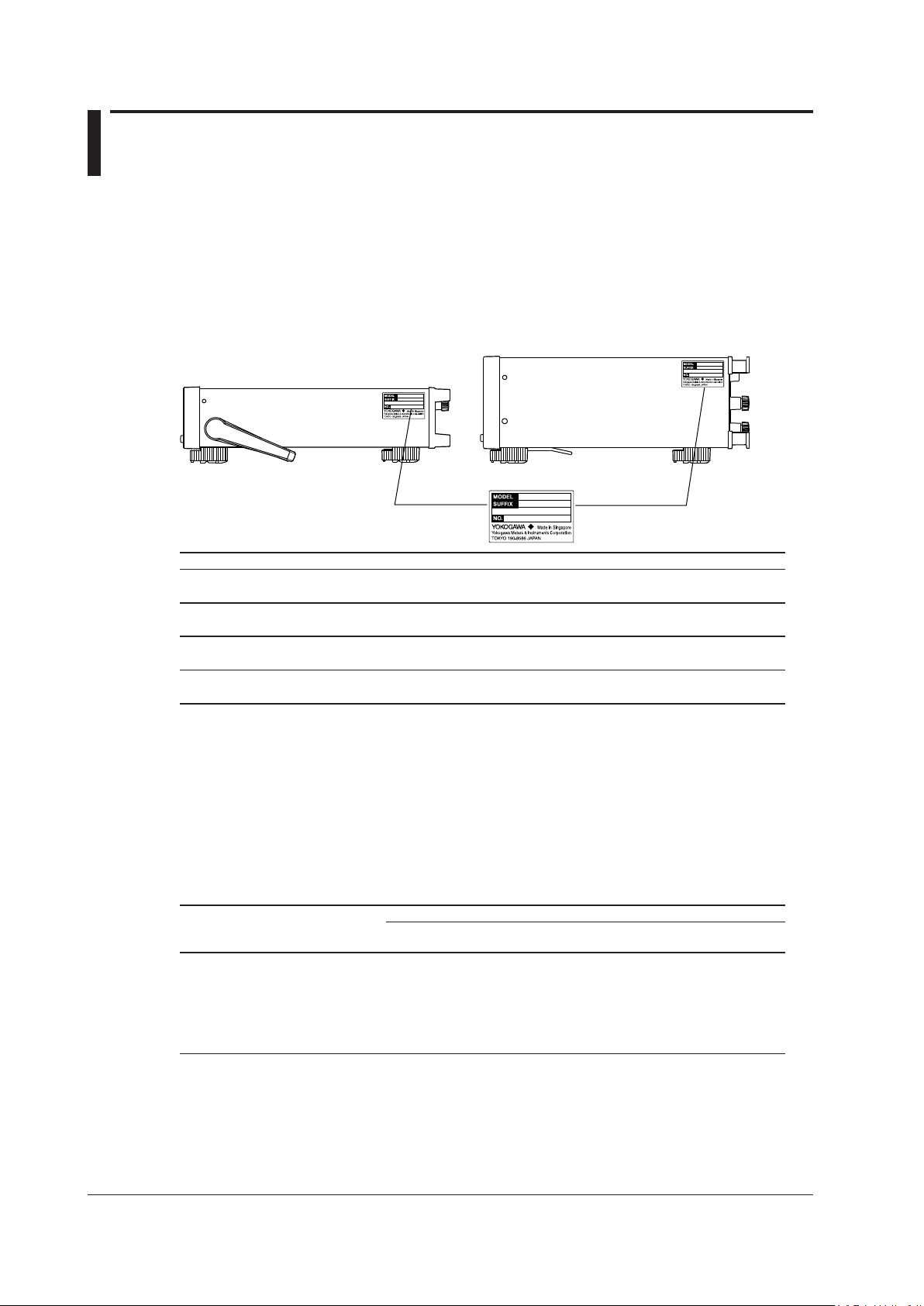
WT310/WT310HC WT330 (Model: WT332/WT333)
Unpack the box and check the contents before operating the instrument. If the wrong items have been
delivered, if items are missing, or if there is a problem with the appearance of the items, contact your
nearest YOKOGAWA dealer.
WT310/WT310HC/WT330
Check that the product that you received is what you ordered by referring to the model name and suffix
code given on the name plate on the left side panel.
The WT330 includes the WT332 and WT333.
Model Suffix Code Description
WT310 WT310 Digital Power Meter
One input element model
WT310HC WT310 Digital Power Meter
One input element/large current model
WT332 WT330 Digital Power Meter
Two input element model
WT333 WT330 Digital Power Meter
Power cord
Communication interface -C1 GP-IB interface
(The instrument is equipped
with one of these.)
Options /C7 Ethernet Communication
1
-D UL/CSA Standard power cord (Part No.: A1006WD)
-F VDE Standard power cord (Part No.: A1009WD)
-Q BS Standard power cord (Part No.: A1054WD)
-R AS Standard power cord (Part No.: A1024WD)
-H GB Standard power cord (Part No.: A1064WD)
-N NBR Standard power cord (Part No.: A1088WD)
-C2 RS-232 interface
/EX1
/EX2
/G5 Harmonic measurement
/DA4 DA output (4CH); for the WT310 or WT310HC
/DA12 DA output (12CH); for the WT332 or WT333
1 Make sure that the attached power cord meets the designated standards of the country and area
that you are using it in.
2 A single instrument cannot have both the /EX1 and /EX2 optio
Three input element model
Maximum rated voltage: 125 V
Maximum rated voltage: 250 V
Maximum rated voltage: 250 V
Maximum rated voltage: 250 V
Maximum rated voltage: 250 V
Maximum rated voltage: 250 V
2
2.5 V/5 V/10 V external input
2
50 mV/100 mV/200 mV/500 mV/1 V/2 V external input
ns.
No. (Instrument number)
When contacting the dealer from which you purchased the instrument, please give them the instrument
number.
Page 5
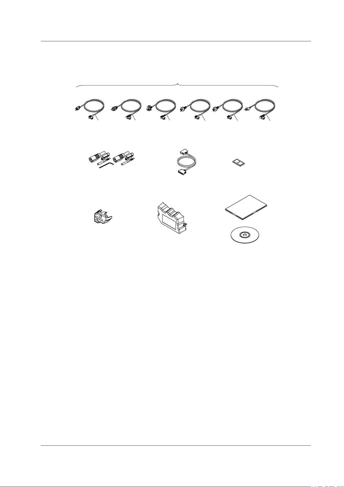
Standard Accessories
D/A cable
3
B9879SX
Current input protection
cover
4
B8212BX
Current input protection
cover
5
B8212FX
Rubber feet
A9088ZM
One set of manuals
6
Safety terminal adapter set
2
758931
UL/CSA Standard
A1006WD
VDE Standard
A1009WD
BS Standard
A1054WD
AS Standard
A1024WD
D
F
Q
R
Power cord (one cord that matches the suffix code is included)
1
GB Standard
A1064WD
H
NBR Standard
A1088WD
N
The instrument is shipped with the following accessories. Make sure that all accessories are present
and undamaged.
Checking the Contents of the Package
1 Make sure that the attached power cord meets the designated standards of the country and area
that you are using it in.
2 Same number of sets as the number of installed input elements
WT310: One set with one hexagonal socket wrench
WT310HC: One set with one hexagonal socket wrench
WT332: Two sets with one hexagonal socket wrench
WT333: Three sets with one hexagonal socket wrench
3
Included with models that have D/A output and remote control (/DA4 or /DA12)
4 For the WT310/WT310HC
5 For the WT332/WT333
6 For information on the types of printed manuals and manuals on the CD that are provided, see
page i.
IM WT310-02EN
iii
Page 6

iv
IM WT310-02EN
Checking the Contents of the Package
CD-R
The CD-R contains the data listed below. To view the PDF user’s manuals, you need Adobe Reader 5.0
or later.
PDFs of the WT310/WT310HC/WT330 User’s Manuals
These manuals are in the Manuals folder.
English
• WT310/WT310HC/WT330 Digital Power Meter User’s Manual
IM WT310-01EN
• WT310/WT310HC/WT330 Digital Power Meter Getting Started Guide
IM WT310-02EN
• WT310/WT310HC/WT330 Digital Power Meter Communication Interface User’s Manual
IM WT310-17EN
Japanese
• WT310/WT310HC/WT330 Digital Power Meter User’s Manual
IM WT310-01JA
• WT310/WT310HC/WT330 Digital Power Meter Getting Started Guide
IM WT310-02JA
• WT310/WT310HC/WT330 Digital Power Meter Communication Interface User’s Manual
IM WT310-17JA
Installer for the WTViewerFreePlus Application Software (For the
WT310/WT310HC/WT330)
• WTViewerFreePlus_Installer.exe
• WTViewerFreePlus (folder)
• YKMUSB (folder)
PDF of the Manual for the WTViewerFreePlus Application Software
These manuals are in the Manuals folder.
English
• Application Software WTViewerFreePlus for WT310/WT310HC/WT330 User’s Manual
IM 760121-02E
Japanese
• Application Software WTViewerFreePlus for WT310/WT310HC/WT330 User’s Manual
IM 760121-02
WARNING
Never play this CD-R on an audio CD player. Doing so may cause loss of hearing or speaker
damage due to the large sounds that may be produced.
Page 7
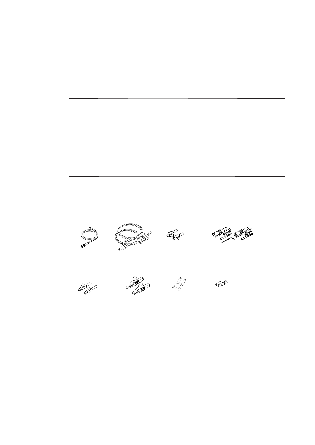
Measurement
lead
758917
Alligator clip
adapter set
758922
Alligator clip
adapter set
758929
Fork terminal
adapter set
758921
Safety terminal
adapter set
758923
External sensor
cable
B9284LK
Safety terminal
adapter set
758931
Conversion adapter
758924
Checking the Contents of the Package
Optional Accessories (Sold separately)
The following optional accessories are available for purchase separately.
For information about ordering accessories, contact your nearest YOKOGAWA dealer.
Item Model/ Min. Q’ty Note
Part No.
External sensor cable B9284LK 1 For connecting to the WT310/WT310HC/WT330’s
external current sensor input connector.
Length: 0.5 m.
Measurement lead 758917 1 Two leads in one set. Used with the 758922 or
758929 adapter (sold separately). Length: 0.75 m.
Rated voltage: 1000 V.*
Safety terminal adapter set 758923 1 Two pieces in one set. Rated voltage 600 V.*
758931 1 Two pieces in one set. Rated voltage 1000 V.*
Alligator clip adapter set 758922 1 Two pieces in one set. For use with measurement
lead 758917.
Rated voltage 300 V.*
758929 1 Two pieces in one set. For use with measurement
lead 758917.
Rated voltage 1000 V.*
Fork terminal adapter set 758921 1 Two pieces in one set. For use with measurement
lead 758917.
Rated voltage 1000 V.* Rated current: 25 A.
Conversion adapter 758924 1 BNC-4 mm socket adapter. Rated voltage: 500 V.*
* The actual voltage that can be used is the lowest voltage of the WT310/WT310HC/WT330 and
cable specifications.
IM WT310-02EN
v
Page 8
vi
IM WT310-02EN
Safety Precautions
This instrument is an IEC safety class I instrument (provided with a terminal for protective earth
grounding).
The general safety precautions described herein must be observed during all phases of operation.
If the instrument is used in a manner not specified in this manual, the protection provided by the
instrument may be impaired. YOKOGAWA assumes no liability for the customer’s failure to comply
with these requirements.
The WT310/WT310HC/WT330 is a power measurement instrument that can measure parameters
such as voltage, current, and power. Do not use this instrument for anything other than its intended
purpose.
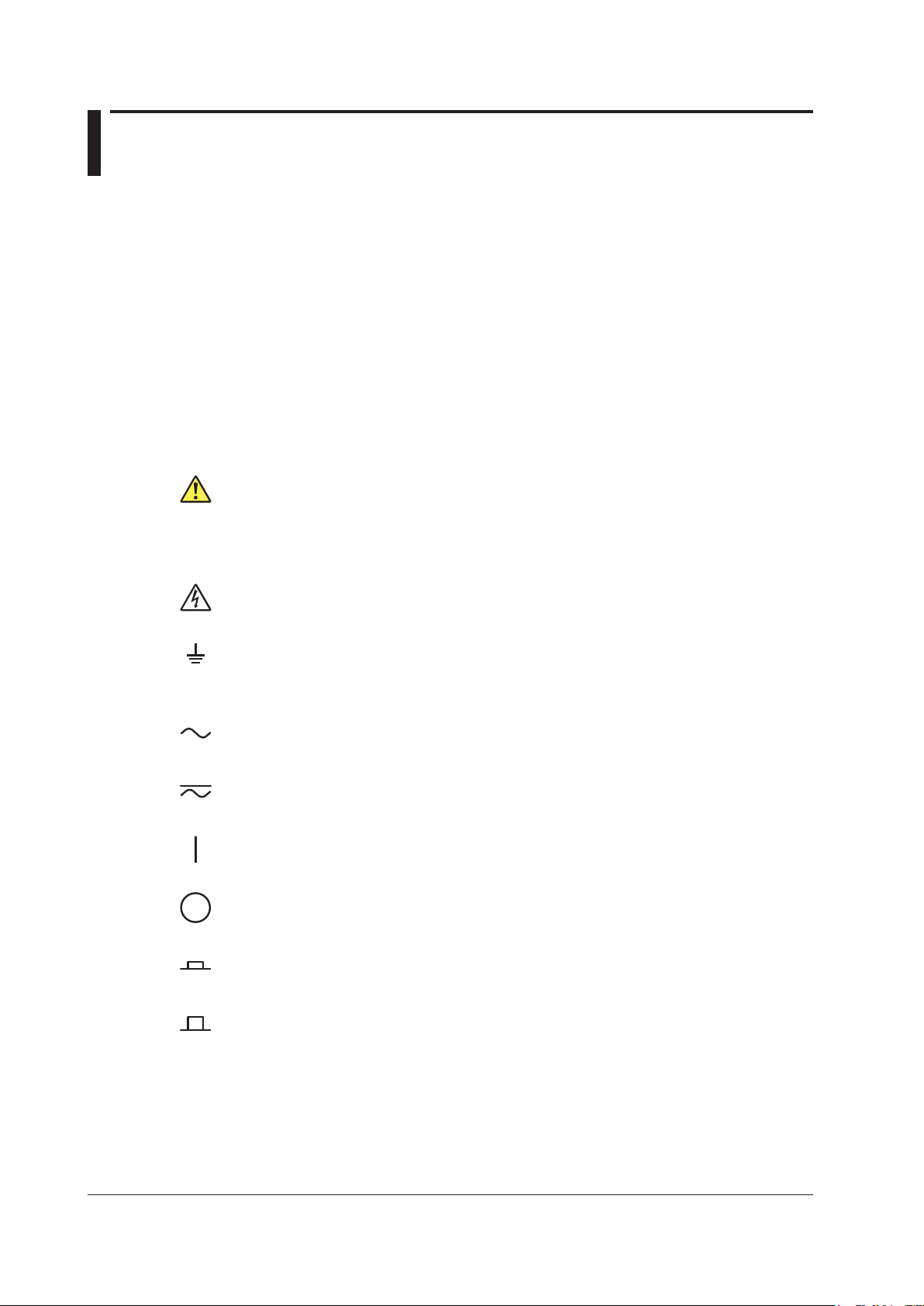
The following symbols are used on this instrument.
Warning: handle with care. Refer to the user’s manual or service manual. This symbol appears
on dangerous locations on the instrument which require special instructions for proper handling
or use. The same symbol appears in the corresponding place in the manual to identify those
instructions.
Electric shock, danger
Ground (earth) or functional ground terminal (do not use this terminal as a protective ground
terminal.)
Alternating current
Both direct and alternating current
ON (power)
OFF (power)
Power-on state
Power-off state
Page 9

Safety Precautions
Failure to comply with the precautions below could lead to injury
or death.
WARNING
Use the Instrument Only for Its Intended Purpose
The WT310/WT310HC/WT330 is a power measurement instrument that can measure
parameters such as voltage, current, and power. Do not use this instrument for anything other
than as a power measurement instrument.
Check the Physical Appearance
Do not use the instrument if there is a problem with its physical appearance.
Use the Correct Power Supply
Make sure that the power supply voltage matches the instrument’s rated supply voltage and
that it does not exceed the maximum voltage range specified for the power cord.
Use the Correct Power Cord and Plug
To prevent the possibility of electric shock or fire, be sure to use the power cord supplied by
YOKOGAWA. The main power plug must be plugged into an outlet with a protective earth
terminal. Do not invalidate this protection by using an extension cord without protective earth
grounding.
Additionally, do not use the power cord supplied with this instrument with another instrument.
Connect the Protective Grounding Terminal
Make sure to connect the protective earth to prevent electric shock before turning on the
power. The power cord that comes with the instrument is a three-prong type power cord.
Connect the power cord to a properly grounded three-prong outlet.
Do Not Impair the Protective Grounding
Never cut off the internal or external protective earth wire or disconnect the wiring of the
protective earth terminal. Doing so may result in electric shock or damage to the instrument.
Do Not Operate with Defective Protective Grounding or Fuses
Do not operate the instrument if the protective earth or fuse might be defective. Check the
grounding and the fuse before operating the instrument.
Do Not Operate in an Explosive Atmosphere
Do not operate the instrument in the presence of flammable gasses or vapors. Doing so is
extremely dangerous.
Do Not Remove Covers
Only qualified YOKOGAWA personnel should remove the instrument’s covers. The inside of
the instrument is dangerous because parts of it have high voltages.
Ground the Instrument before Making External Connections
Securely connect the protective grounding before connecting to the item under measurement
or to an external control unit. Before touching a circuit, turn off its power and check that it has
no voltage.
IM WT310-02EN
Measurement Category
This instrument is a measurement category II product. Do not use it for measurement category
III or IV measurements.
Install or Use the Instrument in Appropriate Locations
•
Do not install or use the instrument outdoors or in locations subject to rain or water.
• Install the instrument so that you can immediately remove the
dangerous condition occurs.
power cord if an abnormal or
vii
Page 10

viii
IM WT310-02EN
Safety Precautions
Connect Cables Correctly
Power meters can measure large voltages and currents directly. If you use a voltage
transformer or a current transformer together with this power meter, you can measure even
larger voltages or currents. When you are measuring a large voltage or current, the power
capacity of the item under measurement becomes large. If you do not connect the cables
correctly, an overvoltage or overcurrent may be generated in the circuit under measurement.
This may lead to not only damage to the power meter and the item under measurement, but
electric shock and fire as well. Be careful when you connect the cables, and be sure to check
the following points.
Before you begin measuring (before you turn the item under measurement on), check that:
•
Cables have been connected to the power meter’s input terminals correctly.
Check that there are no voltage measurement cables that hav
current input terminals.
Check that there are no current measurement cables that have been connected to the
voltage input terminals.
If you are measuring multiphase power, check that there are no mistakes in the phase
wiring.
• Cables have been connected to the power supply and the item under measurement
correctly.
Check that there are no short circuits between terminals or between connected cables.
•
The cables are connected firmly to the current input terminals.
• There are no problems with the current input terminals and the crimping terminals, such as
the presence of foreign substances.
e been connected to the
During measurement (never touch the terminals and the connected cables when the item
under measurement is on), check that:
There no problems with the input terminals and the crimping terminals, such as the
•
presence of foreign substances.
• The input terminals are not abnormally hot.
• The cables are connected firmly to the input terminals.
The terminal connections may become loose over time. If this happens, heat may be
generated due to changes in contact resistance. If you are going to take measurements
using the same setup for a long time, periodically check that the cables are firmly
connected to the terminals. (Be sure to turn both the power meter and the item under
measurement off before you check the connections.)
After measuring (immediately after you turn the item under measurement of
After you measure a large voltage or current, power may rema
under measurement even after you turn it off. This remaining power may lead to electric
shock, so do not touch the input terminals immediately after you turn the item under
measurement off.
varies depending on the item.
The amount of time that power remains in the item under measurement
in for some time in the item
See below for operating environment limitations.
f):
CAUTION
This is a class A instrument designed for an industrial environment. Operation of this product
in a residential area may cause radio interference in which case the user will be required to
correct the interference.
Page 11

Waste Electrical and Electronic Equipment
Waste Electrical and Electronic Equipment (WEEE), DIRECTIVE 2002/96/EC
(This directive is valid only in the EU.)
This product complies with the WEEE Directive (2002/96/EC) marking requirement. This
marking indicates that you must not discard this electrical/electronic product in domestic
household waste.
Product Category
With reference to the equipment
as a “Monitoring and control instruments” product.
Do not dispose in domestic household waste. When disposing products in the EU, contact your
local Yokogawa Europe B. V. office.
types in the WEEE directive Annex I, this product is classified
New EU Battery Directive
New EU Battery Directive, DIRECTIVE 2006/66/EC
(This directive is valid only in the EU.)
Batteries are included in this product. This marking indicates they shall be sorted out and
collected as ordained in ANNEX II in DIRECTIVE 2006/66/EC.
Battery type: Lithium battery
You ca
nnot replace batteries by yourself. When you need to replace batteries, contact your
local Yokogawa Europe B.V.office.
IM WT310-02EN
ix
Page 12

x
IM WT310-02EN
Conventions Used in This Manual
Units
k: Denotes 1000. Example: 100 kS/s (sample rate)
K: Denotes 1024. Example: 720 KB (file size)
Notes
The notes and cautions in this manual are categorized using the following symbols.
Improper handling or use can lead to injury to the user or damage to the
instrument. This symbol appears on the instrument to indicate that the user must
refer to the user’s manual for special instructions. The same symbol appears in
the corresponding place in the user’s manual to identify those instructions. In the
user’s manual, the symbol is used in conjunction with the word “WARNING” or
“CAUTION.”
WARNING
CAUTION
Calls attention to information that is important for the proper operation of the
Note
Calls attention to actions or conditions that could cause serious or fatal injury to
the user, and precautions that can be taken to prevent such occurrences.
Calls attention to actions or conditions that could cause light injury to the user
or cause damage to the instrument or user’s data, and precautions that can be
taken to prevent such occurrences.
software.
Characters That Appear on the 7-Segment LED
Because this instrument uses a 7-segment LED display, numbers, letters, and mathematical symbols
are displayed using special characters. For details, see section 1.3, “Digital Numbers and Characters.”
Page 13
6.
4.
2.
(Display C)
Configure the storage feature.
(Display B)
1.
3.
5.
Confirm
the setting.
Close menu.
Conventions Used in This Manual
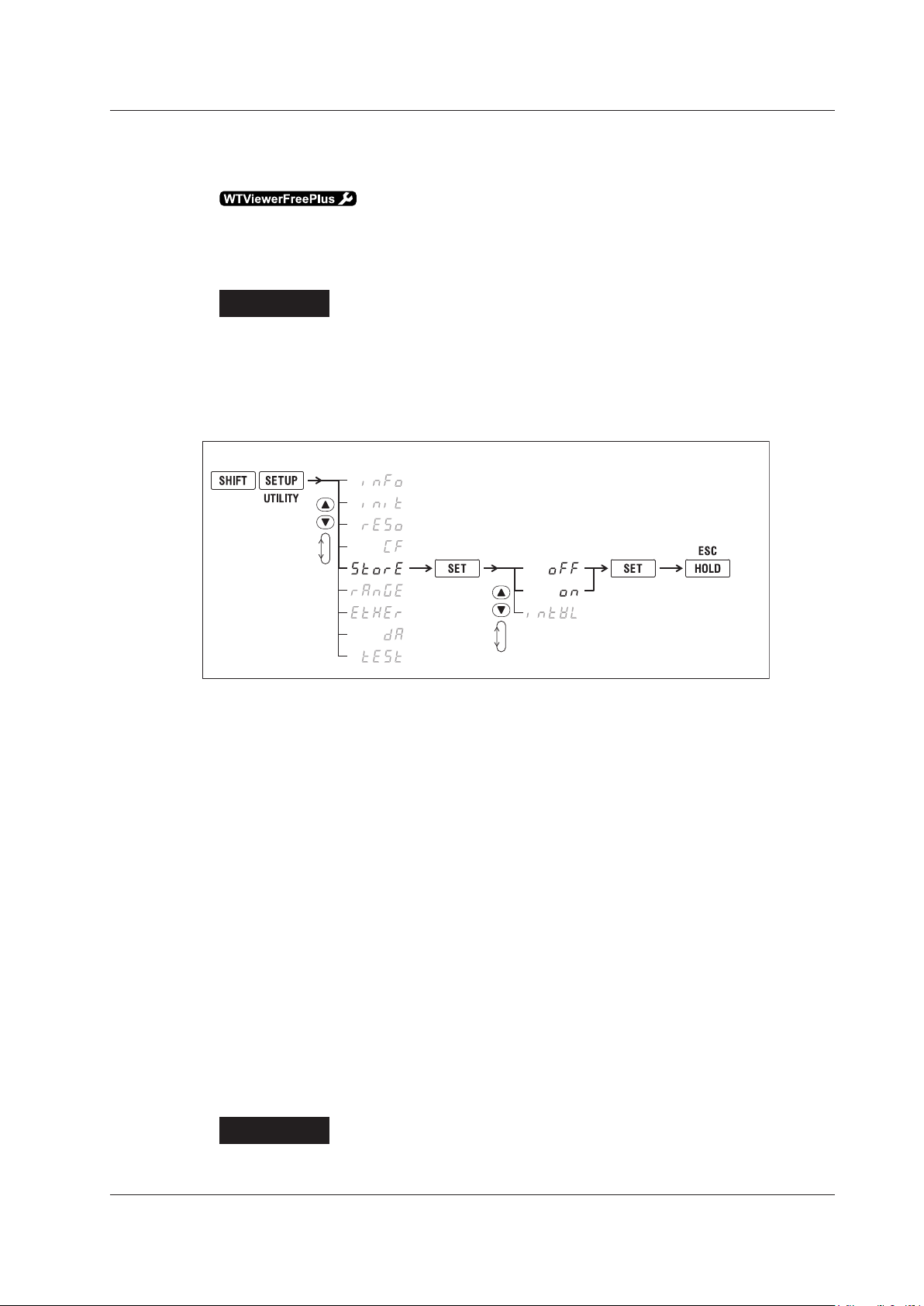
Symbols and Conventions Used in Procedural Explanations
The contents of the procedural explanations are indicated using the following symbols.
This mark appears on the right side of the page to indicate features and settings that can be
operated and configured using the WTViewerFreePlus application software, which comes with the
instrument.
Procedure
Operations are explained using flowcharts. See the example below for an
explanation of how various operations are indicated. All procedures are written
under the assumption that you are starting operation at the beginning of the
procedure, so you may not need to carry out all the steps in a procedure when
you are changing the settings.
Example: Operations for turning the storage feature on and off
The above flow chart indicates the following operations.
You can configure items that are blinking.
Press the SHIFT key so that it illuminates, and then press SETUP (UTILITY).
1.
A menu appears in display B.
Use ▲ or ▼ to select StorE.
2.
Pressing either key cycles through 9 menu items.
Press SET to confirm the selection of StorE.
3.
The StorE function menu that you selected in step 2 appears in display C.
Use ▲ or ▼ to select oFF or on.
4.
Pressing either key cycles through 3 menu items.
Press SET to confirm the selection of oFF.
5.
The selected or set item is confirmed when you press SET.
A menu appears in display B.
Press HOLD (ESC) to return the menu display to the measurement data display.
6.
• When you are making a number positive (no sign) or negative (–) or setting a number, when the
digit in the display that the input will be added to is blank, an underscore flashes at the position of
the digit.
• While you are performing menu operations, to leave the menu display, press HOLD (ESC). All
setting changes that you have confirmed by pressing the SET
Explanation
This section describes the setup items and the limitations regarding the
key will be reflected in the settings.
procedures. It may not give a detailed explanation of the feature. For a detailed
IM WT310-02EN
explanation of the feature, see chapter 1 in the User’s Manual, IM WT310-01EN.
xi
Page 14
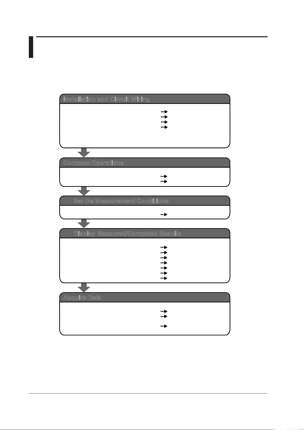
Workflow
Getting Started Guide
Section 2.2
Sections 2.3 and 2.4
Section 2.8
Sections 2.9 to 2.11
Installation and Circuit Wiring
Install the WT310/WT310HC/WT330.
Connect the power supply, and turn the power on.
Select the measurement method.
Wire the circuit under measurement.
Getting Started Guide
Sections 3.1 and 3.2
Section 3.3
Common Operations
Perform key operations.
Initialize settings.
User’s Manual
Chapter 2
Set the Measurement Conditions
Measurement conditions
User’s Manual
Section 4.1
Section 4.2
Section 4.3
Section 4.4
Section 4.5
Chapter 5
Chapter 6
Display Measured/Computed Results
Voltage, current, and active power
Apparent power, reactive power, and power factor
Phase angle and frequency
Peak value
Crest factor, etc.
Integrated power (watt hour)
Harmonic measurement
User’s Manual
Chapter 7
Section 8.4 and chapter 5 of the
Getting Started Guide
Communication Interface
User’s Manual
Acquire Data
Store data to internal memory.
Transmit data using D/A output (option).
Transmit data through the USB, GP-IB,
RS-232, or Ethernet interface.
Read the precautions in sections 2.5 and 2.7 thoroughly before connecting the wires.
Also, if necessary, assemble the input terminal adapter that connects to the voltage
input terminal (see section 2.6) before connecting the wires.
The figure below is provided to familiarize the first-time user with the workflow of WT310/WT310HC/
WT330 operation. For a description of an item, see the relevant section or chapter. In addition to
the sections and chapters that are referenced in the figure below, this manual also contains safety
precautions for handling and wiring the instrument. Be sure to observe the precautions.
xii
IM WT310-02EN
Page 15
1
2
3
4
5
6
7
App
Contents
Checking the Contents of the Package.............................................................................................ii
Safety Precautions ...........................................................................................................................vi
Waste Electrical and Electronic Equipment ..................................................................................... ix
New EU Battery Directive ................................................................................................................ix
Conventions Used in This Manual ....................................................................................................x
Workflow ......................................................................................................................................... xii
Chapter 1 Component Names and Functions
1.1 Front Panel, Rear Panel, and Top Panel .......................................................................... 1-1
1.2 Displayed Items ................................................................................................................ 1-5
1.3 Digital Numbers and Characters ...................................................................................... 1-7
1.4 Keys
Auto Range, Overrange, and Error Indications During Measurement ............................ 1-12
1.5
1.6 System Configuration .....................................................................................................
Chapter 2 Making Preparations for Measurements
2.1 Handling Precautions ....................................................................................................... 2-1
2.2 Installing the Instrument ................................................................................................... 2-3
2.3 Connecting the Power Supply .......................................................................................... 2-6
2.4 Turning the Power Switch On and Off .............................................................................. 2-7
2.5 Precautions When Wiring the Circuit under Measurement .............................................. 2-9
2.6 Assembling the Adapters for the Voltage Input Terminals .............................................. 2-12
2.7 Wiring for Accurately Measuring a Single-phase Device ................................................ 2-14
2.8 Guide for Selecting the Method Used to Measure the Pow
2.9 Wiring the Circuit under Measurement for Direct Input .................................................. 2-16
2.10 Wiring the Circuit under Measurement When Using Current Sensors ........................... 2-31
2.11 Wiring the Circuit under Measurement When Using a Voltage or Current Transformer . 2-38
2.12 Connecting to a PC via USB (Installing WTViewerFreePlus) ......................................... 2-44
Chapter 3 Common Operations
3.1 Key Operation and Functions ........................................................................................... 3-1
3.2 Entering Values ................................................................................................................ 3-3
3.3 Initializing the Settings ...................................................................................................... 3-4
................................................................................................................................. 1-8
1-14
er ........................................ 2-15
Chapter 4 Operating the WT310/WT310HC/WT330
4.1 Setting the Measurement Ranges .................................................................................... 4-1
4.2 Configuring the Wiring System Settings (Only on the WT330) ........................................ 4-4
4.3 Displaying the Voltage, Current, and Active Power on the WT310/WT310HC
4.4 Displaying Voltages, Currents, and Active Powers on the WT330 ...................................
Chapter 5 External I/0 (Option)
5.1 External I/O Connector Pin Arrangement and Pinout ....................................................... 5-1
5.2 Controlling the WT310/WT310HC/WT330 Remotely ....................................................... 5-3
5.3 Producing D/A Output ....................................................................................................... 5-4
IM WT310-02EN
................. 4-5
4-6
xiii
Page 16

xiv
IM WT310-02EN
Contents
Chapter 6 Troubleshooting, Maintenance, and Inspection
6.1 Troubleshooting ................................................................................................................ 6-1
6.2 Error Code Descriptions and Corrective Actions .............................................................. 6-2
6.3 Recommended Part Replacement ................................................................................... 6-3
6.4 Calibration and
Adjustment .............................................................................................. 6-4
Chapter 7 Specifications
7.1 Input ................................................................................................................................. 7-1
7.2 Measurement Items .......................................................................................................... 7-4
7.3 Accuracy ........................................................................................................................... 7-5
7.4
Functions .......................................................................................................................... 7-9
7.5
External Current Sensor Input (/EX1 and /EX2 options) ................................................ 7-14
7.6 D/A Output (/DA4, /DA12 Options)
Remote Control Input/Output Signal (/DA4, /DA12 Options) .......................................... 7-14
7.7
7.8 GP-IB Interface (Standard on -C1) ................................................................................. 7-15
7.9 Serial (RS-232) Interface (Standard on -C2) ..................................................................
7.10 USB PC Interface ........................................................................................................... 7-15
7.1
1 Ethernet Interface(/C7 Option) ....................................................................................... 7-15
7.12 Safety
7.13 General Specifications ................................................................................................... 7-17
7.14 External Dimensions ...................................................................................................... 7-19
Terminal Adapter .................................................................................................
................................................................................. 7-14
7-15
7-16
Appendix
Appendix 1 How to Make Accurate Measurements ..............................................................App-1
Page 17
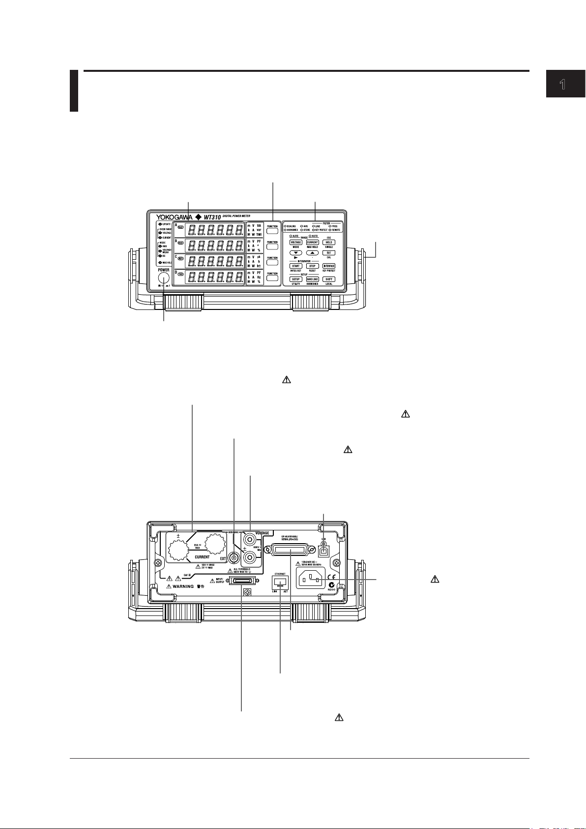
1
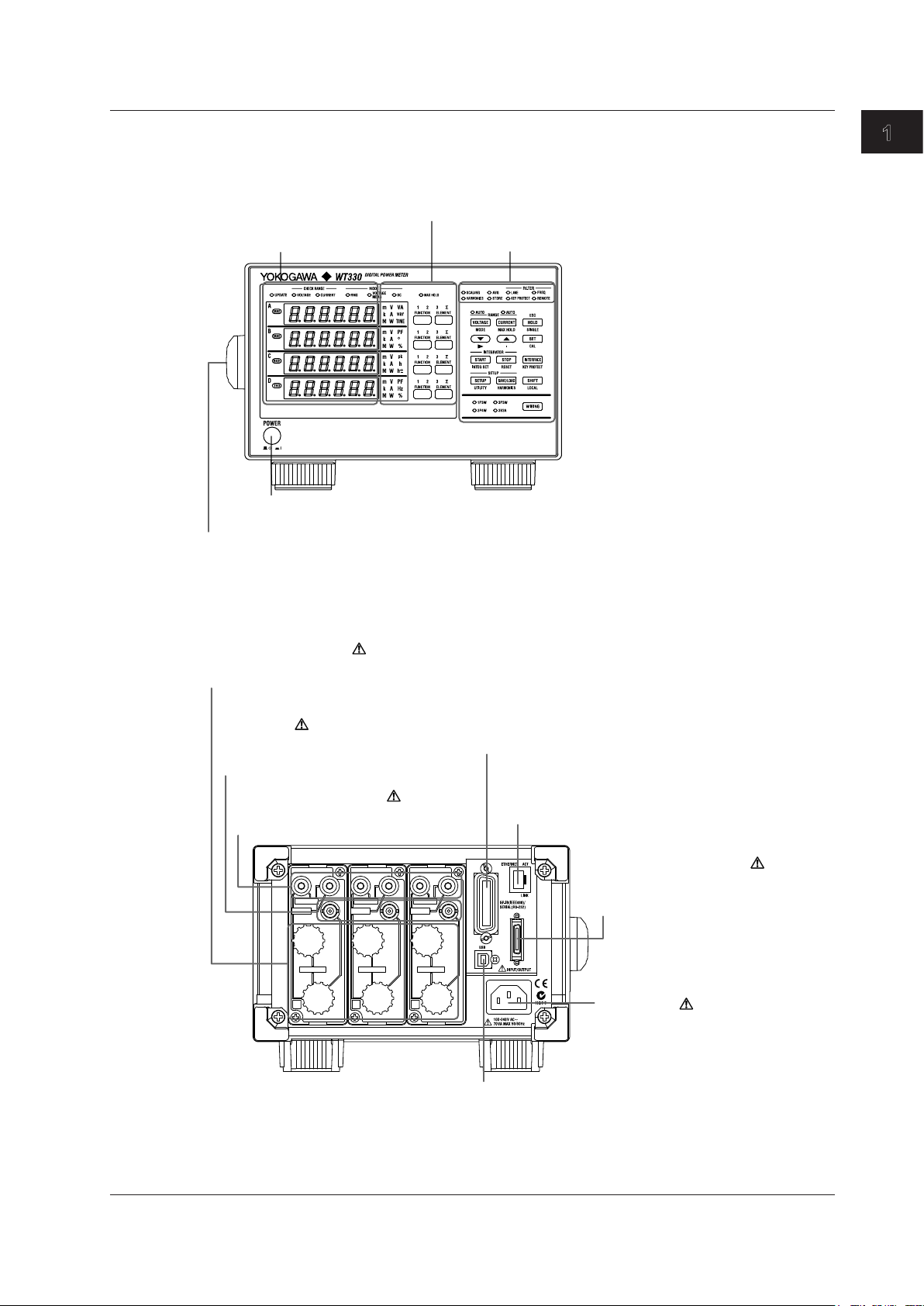
Power switch
→ section 2.4
Handle
Used to carry the
WT310/WT310HC/WT330
→ section 2.1
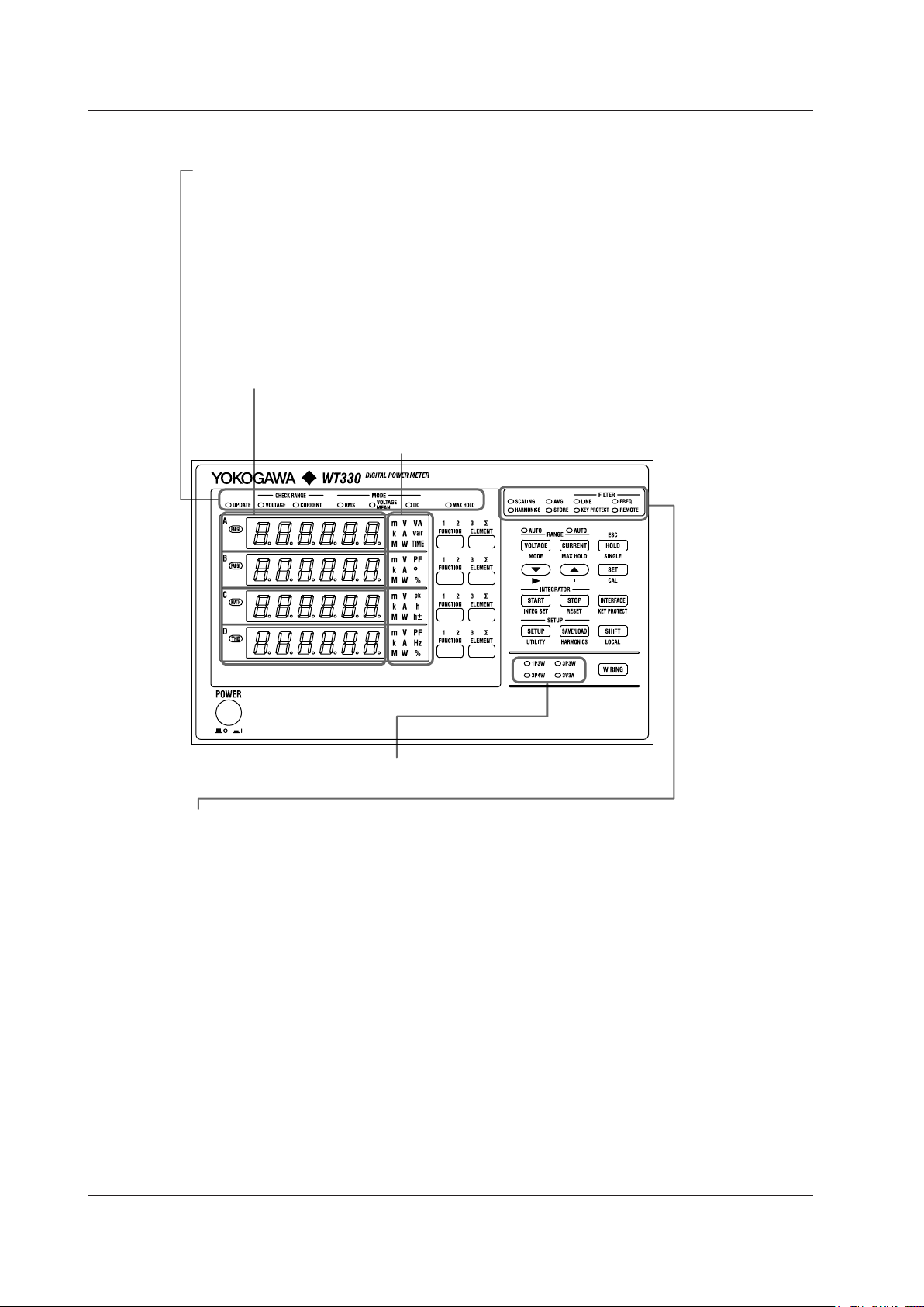
7-segment LED
display
→ section 1.2
Function and unit indicators
→ section 1.2
Keys
→ section 1.4
Power inlet
Power connection → section 2.3
GP-IB or RS-232 connector
Used to communicate with the WT310/WT310HC/WT330
through the GP-IB or RS-232 interface
→ Communication Interface User’s Manual
External I/O connector
For connecting D/A output and remote control cables
→ chapter 5
For connecting voltage measurement cables
→ sections 2.8 to 2.11
Voltage input terminals
Current input terminal
For connecting current measurement
cables → sections 2.8, 2.9, and 2.11
External current sensor input connector
For connecting cables from an external current sensor
→ section 2.10
Ethernet port
Used to connect the WT310/WT310HC/WT330 to a network
→ Communication Interface User’s Manual
USB port for PCs
Used to connect the WT310/WT310HC/WT330 to
a PC that has a USB port
→ Communication Interface User’s Manual
Chapter 1 Component Names and Functions
1.1 Front Panel, Rear Panel, and Top Panel
WT310/WT310HC
Front Panel
Component Names and Functions
Rear Panel
IM WT310-02EN
1-1
Page 18
1-2
IM WT310-02EN
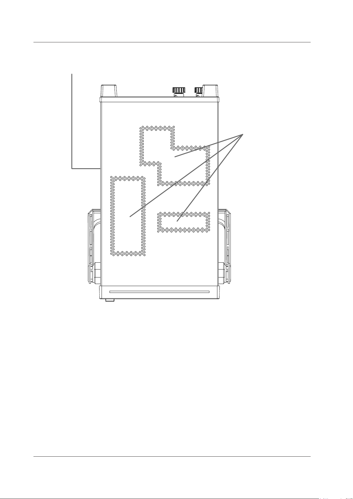
Vent holes → section 2.2
Inlet holes → section 2.2
(There are also inlet holes on the bottom panel.)
1.1 Front Panel, Rear Panel, and Top Panel
Top Panel
Page 19
1
Function, unit, and element indicators
→ section 1.2
Keys
→ section 1.4
Power switch
→ section 2.4
Handle
Used to carry the WT310/WT310HC/WT330
→ section 2.1
7-segment LED
display
→ section 1.2
Power inlet
Power connection → section 2.3
GP-IB or RS-232 connector
Used to communicate with the WT310/WT310HC/WT330
through the GP-IB or RS-232 interface
→ Communication Interface User’s Manual
External I/O connector
For connecting D/A output and remote
control cables
→ chapter 5
For connecting voltage measurement cables
→ sections 2.8 to 2.11
Voltage input terminals
Current input terminal
For connecting current measurement cables
→ sections 2.8, 2.9, and 2.11
External current sensor input
connector
For connecting cables from an
external current sensor
→ section 2.10
Ethernet port
Used to connect the WT310/WT310HC/WT330
to a network
→ Communication Interface User’s Manual
USB port for PCs
Used to connect the WT310/WT310HC/WT330 to a PC
that has a USB port
→ Communication Interface User’s Manual
WT330
Front Panel
1.1 Front Panel, Rear Panel, and Top Panel
Component Names and Functions
Rear Panel
IM WT310-02EN
1-3
Page 20
1-4
IM WT310-02EN
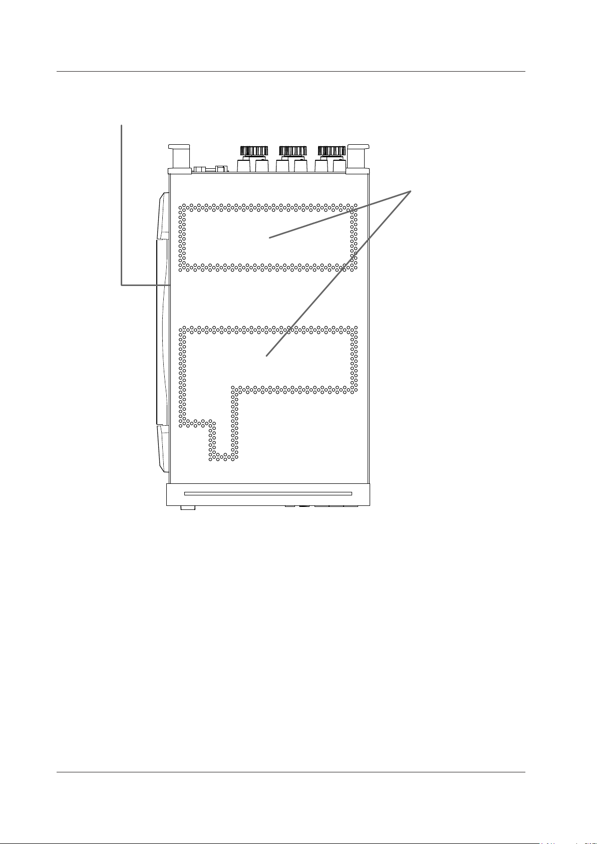
Vent holes → section 2.2
Inlet holes → section 2.2
(There are also inlet holes on the bottom panel.)
1.1 Front Panel, Rear Panel, and Top Panel
Top Panel
Page 21
1
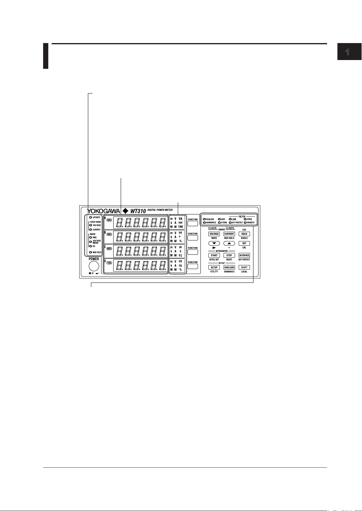
1.2 Displayed Items
Auto range monitor (CHECK RANGE)
Lights when an input signal meets the conditions for auto range switching
Measurement mode indicator (MODE)
Indicates the voltage and current measurement modes
Data update indicator (UPDATE)
Blinks when measurement data is being updated.
MAX HOLD indicator (MAX HOLD)
Lights when MAX HOLD is enabled
Scaling indicator (SCALING)
Lights when scaling is enabled
Averaging indicator (AVG)
Lights when averaging is enabled
Line filter indicator (FILTER-LINE)
Lights when the line filter is enabled
Frequency filter indicator (FILTER-FREQ)
Lights when the frequency filter is enabled
Storage indicator (STORE)
When you start storage, this indicator blinks at the pace at which storage is taking place.
Remote indicator (REMOTE)
Lights when the WT310/WT310HC/WT330 is in remote mode
Harmonic measurement display indicator (HARMONICS)
Lights when the harmonic measurement display is on
Key protection indicator (KEY PROTECT)
Lights when the keys are locked
7-segment LED display
Displays the measured data for the function that you select using the function key
and displays menus when you are using menus to configure the settings
Function and unit indicators
Indicates the type of function and unit that are being shown on the
7-segment LED display
WT310/WT310HC
Component Names and Functions
IM WT310-02EN
1-5
Page 22
1-6
IM WT310-02EN
Auto range monitor (CHECK RANGE)
Lights when an input signal meets the conditions for auto range switching
Measurement mode indicator (MODE)
Indicates the voltage and current measurement modes
Data update indicator (UPDATE)
Blinks when measurement data is being updated.
MAX HOLD indicator (MAX HOLD)
Lights when MAX HOLD is enabled
Scaling indicator (SCALING)
Lights when scaling is enabled
Averaging indicator (AVG)
Lights when averaging is enabled
Line filter indicator (FILTER-LINE)
Lights when the line filter is enabled
Frequency filter indicator (FILTER-FREQ)
Lights when the frequency filter is enabled
Storage indicator (STORE)
When you start storage, this indicator blinks at the pace at which storage is taking place.
Remote indicator (REMOTE)
Lights when the WT310/WT310HC/WT330 is in remote mode
Harmonic measurement display indicator (HARMONICS)
Lights when the harmonic measurement display is on
Key protection indicator (KEY PROTECT)
Lights when the keys are locked
7-segment LED display
Displays the measured data for the function that you select using the function key and
displays menus when you are using menus to configure the settings
Function and unit indicators
Indicates the type of function and unit that are being shown on the
7-segment LED display
Wiring method indicator
Indicates the wiring method
1.2 Displayed Items
WT330
Page 23
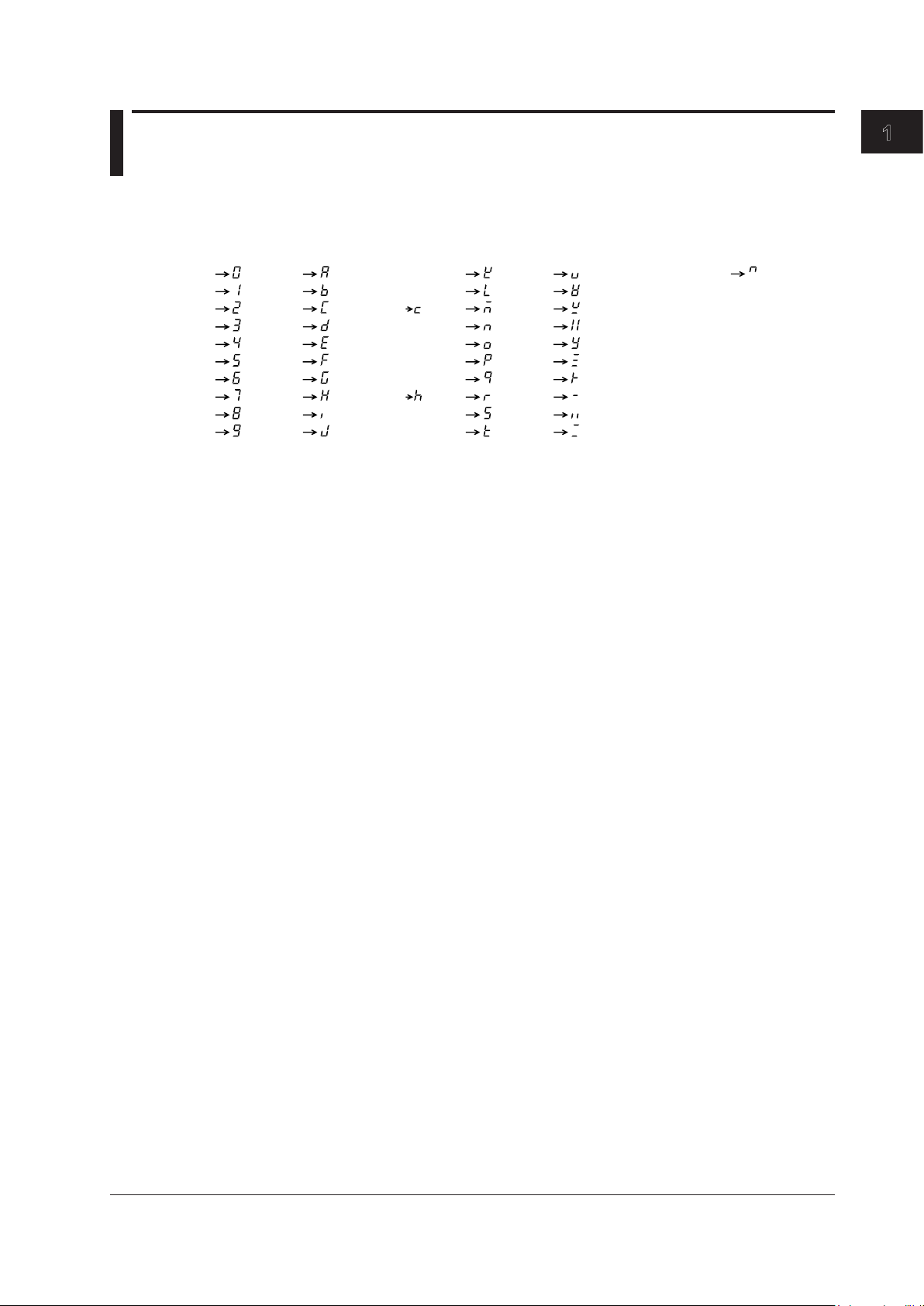
1
1.3 Digital Numbers and Characters
0
1
2
3
4
5
6
7
8
9
A
B
C
D
E
F
G
H
I
J
K
L
M
N
O
P
Q
R
S
T
Lowercase c
Lowercase h
U
V
W
X
Y
Z
+
–
×
÷
^ (exponentiation)
Because this instrument uses a 7-segment LED display, numbers, letters, and mathematical symbols
are displayed using special characters in the manner shown below. Some of the characters shown
below are not used by this instrument.
Component Names and Functions
IM WT310-02EN
1-7
Page 24
1-8
IM WT310-02EN
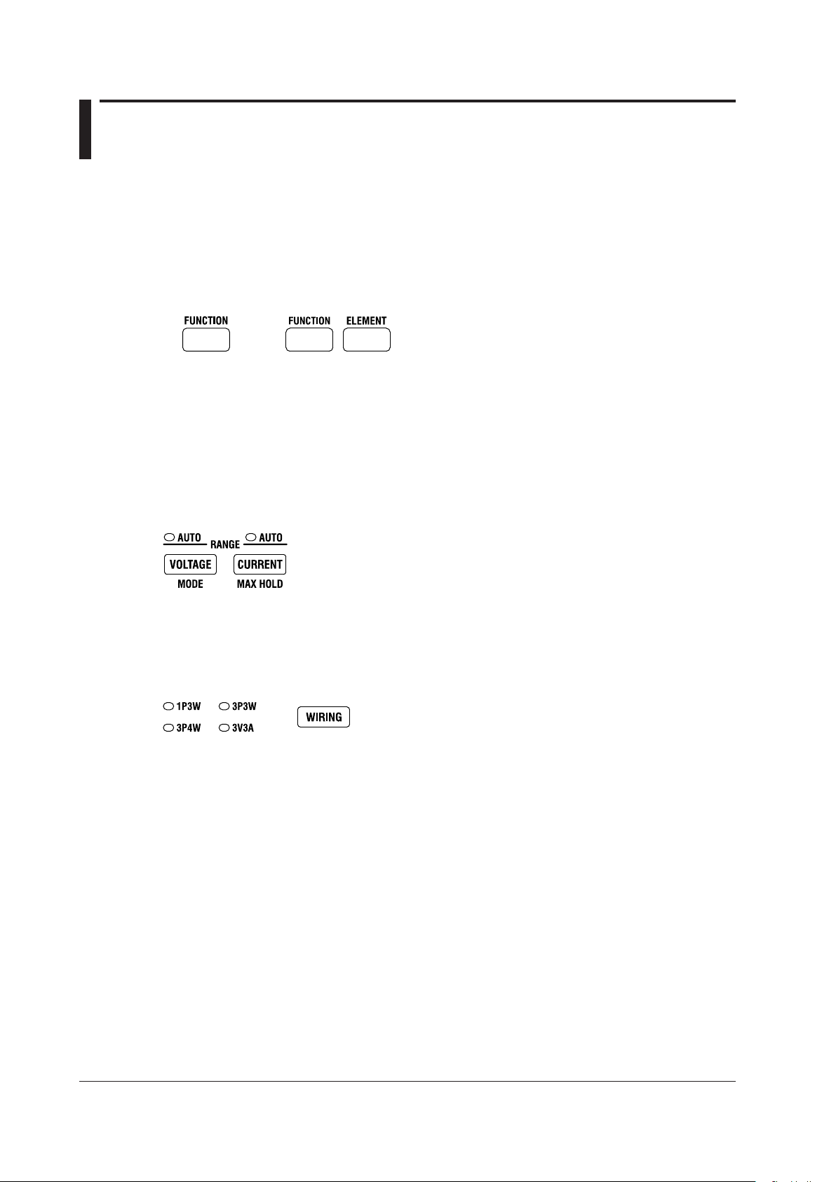
1.4 Keys
WT310/WT310HC WT330
Switching the Display
FUNCTION Key
Choose which function to display.
ELEMENT Key (Only on the WT330)
Choose which input element to display. The indicator of the selected element lights.
Measurement Range and Mode
VOLTAGE Key
Displays the voltage range setting menu. The AUTO indicator lights when the range is set to AUTO.
CURRENT Key
Displays the current range setting menu. The AUTO indicator lights when the range is set to AUTO.
SHIFT+VOLTAGE (MODE) Key
Switches the measurement mode.
Wiring System
WIRING Key (Only on the WT330)
Select the wiring system that corresponds to the wiring system you are using to connect to the voltage
and current terminals on the rear panel.
Page 25

1
Display Hold/MAX Hold
SHIFT+CURRENT (MAX HOLD) Key
Turns the MAX hold feature on and off. When the MAX hold feature is on, the MAX HOLD indicator
lights.
HOLD Key
Switches from updating the display after each data update interval to stopping the series of display
operations and holding the display of the numeric data. The HOLD key lights. If you press HOLD
again, the data starts getting updated again, and the HOLD key light turns off.
SHIFT + HOLD Key
While the numeric data is held, press SINGLE to measure data only once at the set data update
interval and then update and hold the displayed values.
General-Purpose Keys
▲ and ▼ Keys
Select features and set values.
SHIFT+▼ (►) Key
Moves the digit that is being set in a value to the right (or from the farthest right position back to the
farthest left position)
1.4 Keys
Component Names and Functions
SHIFT+▲ (.) Key
Moves the decimal point to the right (or from the farthest right position back to the farthest left position)
SET Key
Confirms the specified range, feature, or value
Zero-Level Compensation
SHIFT+SET Key (CAL)
Executes zero-level compensation. When zero-level compensation is executed, the WT310/WT310HC/
WT330 creates a zero input condition in its internal circuitry and sets the zero level to the level at that
point.
IM WT310-02EN
1-9
Page 26
1-10
IM WT310-02EN
1.4 Keys
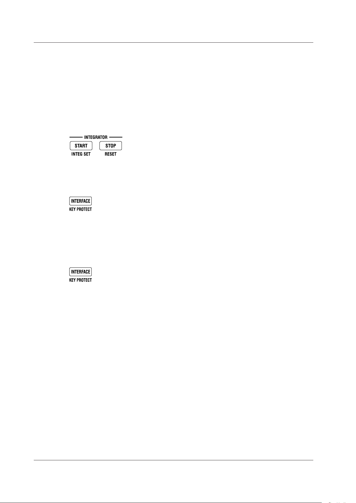
Integrated Power (Watt hour)
START Key
Starts integration
STOP Key
Stops integration
SHIFT+START (INTEG SET) Key
Displays a menu for setting the integration mode, timer, and rated integration time
SHIFT+STOP Key (RESET)
Resets the integrated value and the elapsed integration time.
Communication Interface
INTERFACE Key
Displays the communication interface setting menu and connection information
Key Lock
SHIFT+INTERFACE (KEY PROTECT) Key
Turns key protection on and off.
The key protection indicator lights, and the front panel keys are locked. Press this key combination
again to unlock the keys.
Page 27
1
Other Features
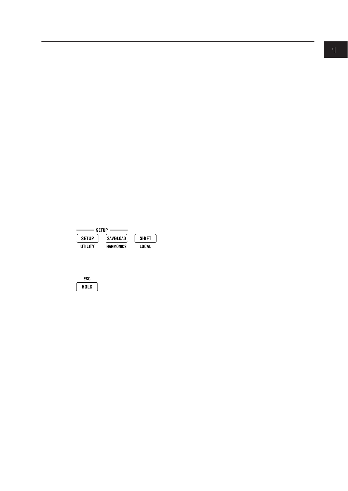
SETUP Key
Set the measurement synchronization source, input filter, scaling, external sensor input, averaging,
computation, data update interval, etc.
SAVE/LOAD Key
Save or load setup data.
SHIFT+SETUP (UTILITY) Key
Displays a menu for displaying system information (model information, suffix code, instrument number,
and firmware version), initializing settings, setting the number of displayed digits, performing self-tests,
and configuring crest factor, storage, network, and D/A output settings.
SHIFT+SAVE/LOAD (HARMONICS) Key
Displays a setting menu for turning the harmonic measurement display on and off, setting the PLL
source, etc.
SHIFT Key
When you press the SHIFT key once, an indicator illuminates, and you can access the features that
are written in purple below each key. Pressing the key again disables the shifted state. Holding the key
for at least two seconds enables SHIFT lock.
SHIFT (LOCAL) Key
Press this key to switch from remote mode (in which the REMOTE indicator is illuminated) to local
mode (in which front panel key operations are valid). This key is disabled when the WT310/WT310HC/
WT330 is in local lockout mode.
1.4 Keys
Component Names and Functions
ESC Key
Pressing this key when a setup menu is showing returns the screen to the waveform data display.
IM WT310-02EN
1-11
Page 28
1-12
IM WT310-02EN
1.5 Auto Range, Overrange, and Error Indications
WT310/WT310HC WT330
During Measurement
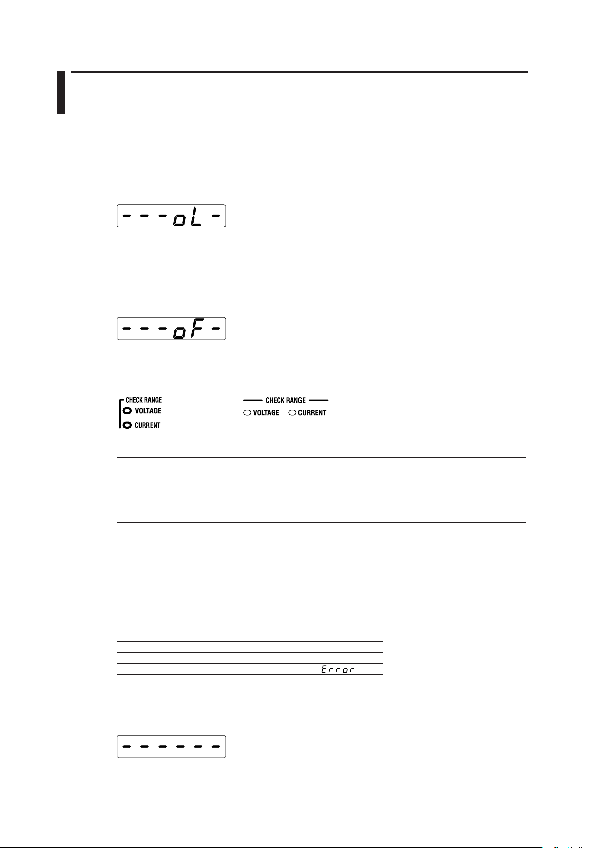
Overrange Indication
The measured voltage and rated current values are determined to be overrange when they exceed
140% of their rated range.* When auto range is enabled, the range is automatically increased, but
if a values exceeds 140% of its maximum range, it is determined to be overrange, and the following
indication appears.
* On the WT310HC, the current is determined to be overrange when it exceeds 110% of the
maximum current range (40 A range).
Computation Overflow Indication
If a computed value cannot be displayed using the specified decimal place or unit, the following
indication appears.
Auto Range Monitor Indications
When an input signal meets the conditions for auto range switching, an indicator lights.
Colors and Meanings of Auto Range Monitor Indicators
Color Description
Red Peak overrange
Magenta Greater than 140% of the rated range (overrange)
Yellow Greater than 130% of the rated range and not more than 140% (condition for raising the auto range)
Cyan 30% or less of the rated range (condition for reducing the auto range)
If the range is already at the minimum measurement range, this indicator will not light even when
values are 30% or less of the rated range.
1 On the WT310HC, the current is determined to be overrange when it exceeds 110% of the maximum current
range (40 A range).
2 On the WT310HC, the current is determined to be overrange when it exceeds 100% of the maximum current
range (40 A range).
1
Indications When the Measured Value Is Too Small
When the measured voltage or current is 0.5% or less of the rated range (1% or less when the
crest factor is set to 6), the following indications appear. These indications only appear when the
measurement mode is RMS or VOTLAGE MEAN.
Function Indication
Voltage, current, apparent power, or reactive power A zero appears.
Power factor or phase angle
Measurement Suspension/No Data Indication (Dashes)
When the measurement range, function, or element is switched and the displayed contents change or
when there is no data to display, the following dashes are displayed temporarily.
2
Page 29

1
1.5 Auto Range, Overrange, and Error Indications During Measurement
Error
Displayed in cases such as when a measured value is outside of its determined range.
Component Names and Functions
IM WT310-02EN
1-13
Page 30
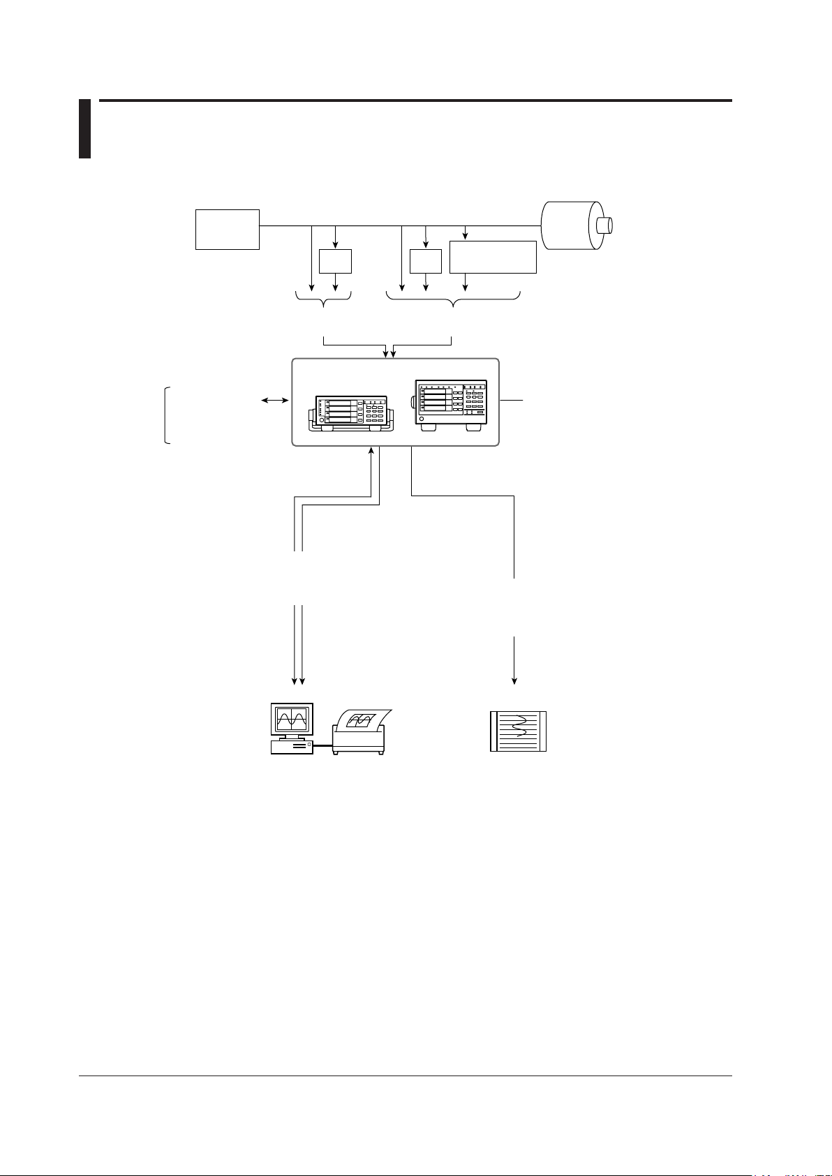
1.6 System Configuration
Power
Supply
Load
VT
CT
Voltage
(Apply one of them.)
Current
(Apply one of them.)
Current sensor
(optional)
Remote control signal
(optional)
Internal memory
Numeric data storage
Recorder
Numeric data
Setup parameters
PC
Printer
Integration start
Integration stop
Hold/
single
USB interface/
GP-IB interface
*
/
RS-232 interface*/
Ethernet interface (optional)
D/A output (option)
Measured values
are transmitted
as DC voltages.
WT310/WT310HC/WT330
* The WT310/WT310HC/WT330 is standard-equipped with a GP-IB or RS-232 interface (whichever
you choose).
1-14
IM WT310-02EN
Page 31

1
2
Chapter 2 Making Preparations for Measurements
2.1 Handling Precautions
Safety Precautions
If you are using this instrument for the first time, make sure to read “Safety Precautions” on pages vi to
viii.
Do Not Remove the Case
Do not remove the case from the instrument. Some parts of the instrument use high voltages and
are extremely dangerous. For internal inspection and adjustment, contact your nearest YOKOGAWA
dealer.
Unplug If Abnormal Behavior Occurs
If you notice smoke or unusual odors coming from the instrument, immediately turn off the power and
unplug the power cord. Also, turn off the power to any circuits under measurement that are connected
to the input terminals. Then, contact your nearest YOKOGAWA dealer.
Do Not Damage the Power Cord
Nothing should be placed on top of the power cord. The power cord should also be kept away from
any heat sources. When removing the plug from the power outlet, do not pull on the cord. Pull from the
plug. If the power cord is damaged, purchase a replacement with the same part number as the one
indicated on page iii.
Making Preparations for Measurements
General Handling Precautions
Do Not Place Objects on Top of the Instrument
Never stack the instrument or place other instruments or any objects containing water on top of it.
Doing so may damage the instrument.
Keep Electrically Charged Objects Away from the Instrument
Keep electrically charged objects away from the input terminals. They may damage the internal
circuitry.
Unplug during Extended Non-Use
Turn off the power to the circuit under measurement and the instrument and remove the power cord
from the outlet.
IM WT310-02EN
2-1
Page 32

2-2
IM WT310-02EN
WT310/WT310HC WT330
2.1 Handling Precautions
When Carrying the Instrument
First, turn off the circuit under measurement and remove the measurement cables. Then, turn off the
instrument and remove the power cord and any attached cables. When carrying the instrument, use
the handle as shown in the following figure, or use both hands to hold the instrument firmly.
When Cleaning the Instrument
When cleaning the case or the operation panel, turn off the circuit under measurement and the
instrument and remove the instrument’s power cord from the outlet. Then, wipe the instrument
lightly with a clean dry cloth. Do not use chemicals such as benzene or thinner. Doing so may cause
discoloring and deformation.
Page 33

1
2
2.2 Installing the Instrument
Installation Conditions
WARNING
• Do not install the instrument outdoors or in locations subject to rain or water.
• Install the instrument so that you can immediately remove the power cord if an abnormal or
dangerous condition occurs.
Install the instrument in an indoors environment that meets the following conditions.
Flat, Even Surface
Use the instrument on a stable surface that is level in all directions. If you use the instrument on an
unstable or tilted surface, the accuracy of its measurements may be impeded.
Well-Ventilated Location
Inlet and vent holes are located on the top and bottom of the instrument. To prevent internal
overheating, allow at least 20 mm of space around the inlet and vent holes.
When connecting measurement wires and other various cables, allow extra space for operation.
Making Preparations for Measurements
CAUTION
If you block the inlet or outlet holes on the instrument, it will become hot and may break down.
Ambient Temperature and Humidity
Ambient temperature: 5 to 40°C
Ambient humidity: 20 to 80% RH
(No condensation)
Do Not Install the Instrument in the Following Places
• In direct sunlight or near heat sources
• In an environment with excessive amounts of soot, steam, dust, or corrosive gas
• Near strong magnetic field sources
• Near high-voltage equipment or power lines
• In an environment that is subject to large levels of mechanical vibration
• On an unstable surface
• Outdoors or in locations subject to rain or water
Note
• For the most accurate measurements, use the instrument in the following kind of environment.
Ambient temperature: 23°C ± 5°C Ambient humidity: 30% RH to 75% RH (no condensation)
When using the instrument in a place where the ambient temperature is 5°C to 18°C or 28°C to 40°C, add the
temperature coefficient to the accuracy as specified in chapter 7.
• When installing the instrument in a place where the ambient humidity is 30% or less, take measures to
prevent static electricity such as using an anti-static mat.
• Condensation may occur if the instrument is moved to another place where the ambient temperature or
humidity is higher, or if the temperature changes rapidly. In these kinds of circumstances, wait for at least an
hour before using the instrument, to acclimate it to the surrounding temperature.
IM WT310-02EN
2-3
Page 34

2-4
IM WT310-02EN
1
2
3
4
5
6
7
8
1
3
Rotating base
Pull this out approximately 2 mm
to 3 mm, and rotate the handle.
Handle stop positions (We recommend that you use positions 1, 3, 5, and 8. Do not place a heavy load
on the WT310/WT310HC/WT330 when the handle is in stop position 2 or 4.)
Movable legs
2.2 Installing the Instrument
Storage Location
Do not store the instrument:
• Where the relative humidity is greater than 80% • Where the level of mechanical vibration is high
• In direct sunlight • Where there are corrosive or explosive gasses
• Where the temperature is 60°C or higher • Where an excessive amount of soot, dust, salt,
• Near a strong source of heat or moisture • Where water
We recommend that the instrument be stored in an environment where the temperature is between 5°C
and 40°C and the relative humidity is between 20% RH and 80% RH.
Installation Position
Desktop
Place the instrument in a horizontal position or tilt it on its handle or movable legs. Place the instrument
on a flat, level surface as shown in the figure below.
• WT310/WT310HC
To use the handle as a stand to tilt the instrument, first check that the handle is fixed in place,
and then position the instrument. To rotate the handle, first pull the handle’
approximately 2 mm to 3 mm on both the left and right sides of the instrument, and then rotate it
slowly to one of its stop positions.
or iron is present
, oil, or chemicals may splash onto
the instrument
s rotary axis out
• WT330
WARNING
• When adjusting the WT310/WT310HC handle, be careful not to injure your hand with the
edges of the handle.
• When you put away the handle or movable legs, be careful not to get your hand caught
between the handle or movable legs and the instrument.
• Handling the movable legs or handle without firmly supporting the instrument can be
dangerous. Please take the following precautions.
• Only handle the movable legs or handle when the instrument is on a stable surface.
• Do not handle the movable legs or handle when the instrument is tilted.
Do not place the instrument in any position other than those shown in the above figures.
•
Rubber Feet
If the instrument is installed so that it is flat as shown in the above figure, rubber stoppers can be
attached to the feet to prevent the instrument from sliding. One set of rubber stoppers (two stoppers)
are included in the package.
Page 35

1
2
Rotating base
To remove the handle, rotate
the handle to position 8, and
then pull out the rotating base
of the handle by approximately
10 mm on both sides.
WT310/WT310HC WT330
Cover
Cover
Handle
2.2 Installing the Instrument
Rack Mounting
To mount the instrument on a rack, use a rack mount kit (sold separately).
• For the WT310/WT310HC
Item Model Note
Rack mount kit 751533-E2 For EIA single mount
Rack mount kit 751533-J2 For JIS single mount
Rack mount kit 751534-E2 For EIA dual mount
Rack mount kit 751534-J2 For JIS dual mount
• For the WT330
Item Model Note
Rack mount kit 751533-E3 For EIA single mount
Rack mount kit 751533-J3 For JIS single mount
Rack mount kit 751534-E3 For EIA dual mount
Rack mount kit 751534-J3 For JIS dual mount
A summary of the procedure for mounting the instrument on a rack is given below. For detailed
instructions, see the manual that is included with the rack mount kit.
Remove the handle from the instrument.
1.
• WT310/WT310HC
Rotate the handle to position 8 (see the figure on the previous page), and then pull out the rotating base
of the handle by approximately 10 mm on both sides.
• WT330
Remove the handle attachment section cover, and remove the handle attachment screws.
Making Preparations for Measurements
2.
3.
4.
5.
6.
Note
• When rack-mounting the instrument, allow at least 20 mm of space around the inlet and exhaust holes to
• Make sure to provide adequate support from the bottom of the instrument. The support should not block the
For detailed instructions for the procedures below, see the manual that is included with the rack mount kit.
Remove the feet from the bottom of the instrument.
Peel off the seals over the rack mount attachment holes on both side panels of the instrument,
and pull out the rubber rivets.
Place seals over the feet and handle attachment holes.
Attach the rack mount kit to the instrument.
Mount the instrument on a rack.
prevent internal heating.
inlet and vent holes.
IM WT310-02EN
2-5
Page 36

2-6
IM WT310-02EN
2.3 Connecting the Power Supply
WT310/WT310HC WT330
Three-prong outlet
Before Connecting the Power Supply
To prevent electric shock and damage to the instrument, follow the warnings below.
WARNING
• Make sure that the power supply voltage matches the instrument’s rated supply voltage
and that it does not exceed the maximum voltage range specified for the power cord.
• Connect the power cord after checking that the power switch of the instrument is turned
OFF.
• T
o prevent fire and electric shock, only use a power cord supplied by YOKOGA
• To avoid electric shock, be sure to ground the instrument. Connect the power cord to a
three-prong power outlet with a protective earth terminal.
• Do not use an ungrounded extension cord. If you do, the instrument will not be grounded.
• Use an AC outlet that complies with the power cord provided a
protective grounding. If such an AC outlet is unavailable and protective grounding cannot
be furnished, do not use the instrument.
Connecting the Power Cord
Check that the instrument’s power switch is off.
1.
Connect the power cord plug to the power inlet on the rear panel of the instrument.
2.
Connect the other end of the cord to an outlet that meets the following conditions. Use a
3.
grounded three-prong outlet.
Item Specification
Rated supply voltage 100 VAC to 120 VAC, 200 VAC to 240 VAC
Permitted supply voltage range 90 VAC to 132 VAC, 180 VAC to 264 VAC
Rated power supply frequency 50/60 Hz
Permitted supply frequency range 48 Hz to 63 Hz
Maximum power consumption WT310/WT310HC: 50 VA, WT330: 70 VA
*
This instrument can use a 100 V or a 200 V power supply. The maximum rated voltage differs according
to the type of power cord. Before you use the instrument, check that the voltage supplied to it is less
than or equal to the maximum rated voltage of the power cord provided with it (see page v for the
maximum voltage rating).
WA.
nd securely connect the
Page 37

1
2
2.4 Turning the Power Switch On and Off
POWER
OFF ON
WT310/WT310HC WT330
Before Turning On the Power, Check That:
• Theinstrumentisinstalledproperly.→section2.2,“InstallingtheInstrument”
• Thepowercordisconnectedproperly.→section2.3,“ConnectingthePowerSupply”
Power Switch Location
The power switch is located in the lower left of the front panel.
Turning the Power Switch On and Off
The power switch is a push button. Press the button once to turn the instrument on and press it again
to turn the instrument off.
Making Preparations for Measurements
Operations Performed When the Power Is Turned On
When the power switch is turned on, a self-test starts automatically. When the self-test completes
successfully, the screen that was displayed immediately before the power was turned off appears.
Note
• After turning the power off, wait at least 10 seconds before you turn it on again.
When the Power-on Operation Does Not Finish Normally
• If the instrument does not operate as described above when the power switch is turned on, turn the power
switch off, and then:
• Check that the power cord is securely connected.
• Checkthatthecorrectvoltageiscomingtothepoweroutlet.→section2.3,“ConnectingthePower
Supply”
• After checking the above, try turning on the power while holding down SET to initialize the settings (reset
them to their factory defaults). For details about initializing the settings, see section 3.3, “Initializing
Settings.”
• If the instrument still does not work properly, contact your nearest YOKOGAWA dealer for repairs.
• If an error code is displayed, see section 6.2, “Error Code Descriptions and Corrective Actions,” and take
the appropriate actions.
• It may take a few seconds for the startup message to appear.
To Make Accurate Measurements
• Allow the instrument to warm up for at least 30 minutes after turning on the power switch.
• Aftertheinstrumentwarmsup,executezero-levelcompensation.→section8.3oftheUser’s
Manual, IM WT310-01EN
IM WT310-02EN
2-7
Page 38

2-8
IM WT310-02EN
All the LEDs light.
Power on
Measurement data display
Model: WT310, WT310HC, WT332, or WT333
Firmware version
1
2
3
2.4 Turning the Power Switch On and Off
Operations Performed When the Power Is Turned Off
After the power is turned off, the instrument stores the setup parameters in its memory before shutting
down. The same is true when the power cord is disconnected from the outlet. The next time the power
is turned on, the instrument powers up using the stored setup parameters.
Note
The instrument stores the settings using an internal lithium battery. When the lithium battery voltage falls
below a specified value, you will no longer be able to store setup parameters, and error code 901 will
appear on the screen when you turn on the power (see section 6.2, “Error Code Descriptions and Corrective
Actions”). If this message appears frequently, you need to replace the battery soon. Do not try to replace the
battery yourself. Contact your nearest YOKOGAWA dealer to have the battery replaced.
Power-on Messages
Page 39

1
2
2.5 Precautions When Wiring the Circuit under Measurement
To prevent electric shock and damage to the instrument, follow the warnings below.
WARNING
• Ground the instrument before connecting measurement cables. The power cord that comes
with the instrument is a three-prong cord. Insert the power cord into a grounded threeprong outlet.
•
Turn the circuit under measurement off before connecting and disconnecting cables to it.
Connecting or removing measurement cables while the power is on is dangerous.
Do not wire a current circuit to the voltage input terminal or a voltage circuit to the current
•
input terminal.
• Strip the insulation covers of measurement cables so that when they are wired to the input
terminals, the conductive parts (bare wires) do not protrude from the terminals.
sure to fasten the input terminal screws securely so that cables do not come loose.
• When connecting measurement cables to the voltage input ter
measurement cables that have safety terminals that cover their conductive parts. Using
a terminal with bare conductive parts (such as a banana plug) can be dangerous if the
terminal comes loose.
• When connecting cables to the external current sensor input terminals, only connect cables
that have safety terminals that cover their conductive parts. Using a connector with bare
conductive parts can be dangerous if the terminal comes loose.
• When you apply current directly to the current input terminals to measure it, the voltage of
the item under measurement appears at the external sensor input connector
electric shock, remove the cable connected to the external sensor.
• When the voltage of the circuit under measurement is being applied to the current input
terminals, do not touch the external current sensor input terminals. Doing so is dangerous
because the terminals are electrically connected inside the instrument.
• When connecting a measurement cable from an external current sensor to an external
current sensor input connector, remove the cables connected to the current input terminals.
Also, when the voltage of the circuit under measurement is being applied to the external
current sensor input terminals, do not touch the current input terminals. Doing so is
dangerous because the terminals are electrically connected inside the instrument.
•
When using an external voltage transformer (VT) or current transformer (CT), make sure
that it has enough dielectric strength for the voltage (U) being measured (2U + 1000 V
recommended). Also, make sure that the secondary side of the CT does not become an
open circuit while the power is being applied. If this happens, high voltage will appear at
the secondary side of the CT
•
When using an external current sensor, make sure to use a sensor that comes in a case.
The conductive parts and case should be insulated, and the sensor should have enough
dielectric strength for the voltage of the circuit under measurement. Using a bare sensor is
dangerous, because there is a high probability that you might accidentally touch it.
• When using a shunt-type current sensor as an external current sensor, turn off the circuit
under measurement before you connect the sensor
while the power is on is dangerous.
• When using a clamp-type current sensor as an external current sensor, make sure that
you understand the voltage of the circuit under measurement and the specifications and
handling of the clamp-type sensor, and then confirm that there are no dangers, such as
shock hazards.
• For safety reasons, when using the instrument after mounting it on a rack, furnish a switch
for turning off the circuit under measurement from the front side of the rack.
• For safety reasons, after you connect the measurement cable
attach the current input protection cover (screw tightening torque: 0.6 N•m). Make sure that
the conductive parts do not protrude from the protection cover.
, making it extremely dangerous.
. Connecting or removing the sensor
minals, only connect
s, use the included screws to
Also, make
. To prevent
Making Preparations for Measurements
IM WT310-02EN
2-9
Page 40

2-10
IM WT310-02EN
2.5 Precautions When Wiring the Circuit under Measurement
• To make the protective features effective, before applying the voltage or current from the
circuit under measurement, check that:
• The power cord provided with the instrument is being used to connect to the power
supply and that the instrument is grounded.
• The instrument is turned on.
•
The current input protection cover provided with the instrument is attached.
• When the instrument is turned on, do not apply a signal that e
to the voltage or current input terminals. When the instrument is turned off, turn the circuit
under measurement off. For information about other input terminals, see the specifications
in chapter 6.
Instantaneous maximum allowable input (within 20 ms)
Voltage input
Peak value of 2.8 kV or rms value of 2 kV, whichever is less.
Current input
Direct input
•
WT310 and WT330
When the crest factor is 3: 0.5 A to 20 A
When the crest factor is 6: 0.25 A to 10 A
Peak value of 450 A or rms value of 300 A, whichever is less.
• WT310
When the crest factor is 3: 5 mA to 200 mA
When the crest factor is 6: 2.5 mA to 100 mA
Peak value of 150 A or rms value of 100 A, whichever is less.
• WT310HC
When the crest factor is 3: 1 A to 40 A
When the crest factor is 6: 0.5 A to 20 A
Peak value of 450 A or rms value of 300 A, whichever is less.
External sensor input
Peak value less than or equal to 10 times the range.
xceeds the following values
Instantaneous maximum allowable input (1 s or less)
Voltage input
Peak value of 2 kV or rms value of 1.5 kV, whichever is less.
Current input
Direct input
WT310 and WT330
•
When the crest factor is 3: 0.5 A to 20 A
When the crest factor is 6: 0.25 A to 10 A
Peak value of 150 A or rms value of 40 A, whichever is less.
• WT310
When the crest factor is 3: 5 mA to 200 mA
When the crest factor is 6: 2.5 mA to 100 mA
Peak value of 30 A or rms value of 20 A, whichever is less.
• WT310HC
When the crest factor is 3: 1 A to 40 A
When the crest factor is 6: 0.5 A to 20 A
Peak value of 150 A or rms value of 44 A, whichever is less.
External sensor input
Peak value less than or equal to 10 times the range.
Page 41

1
2
2.5 Precautions When Wiring the Circuit under Measurement
Continuous maximum allowable input
Voltage input
Peak value of 1.5 kV or rms value of 1.0 kV, whichever is less.
Current input
Direct input
• WT310 and WT330
When the crest factor is 3: 0.5 A to 20 A
When the crest factor is 6: 0.25 A to 10 A
Peak value of 100 A or rms value of 30 A, whichever is less.
• WT310
When the crest factor is 3: 5 mA to 200 mA
When the crest factor is 6: 2.5 mA to 100 mA
Peak value of 30 A or rms value of 20 A, whichever is less.
• WT310HC
When the crest factor is 3: 1 A to 40 A
When the crest factor is 6: 0.5 A to 20 A
Peak value of 100 A or rms value of 44 A, whichever is less.
External sensor input
Peak value less than or equal to 5 times the range.
CAUTION
Use measurement cables with dielectric strengths and current capacities that are appropriate
for the voltage or current being measured.
Example: When making measurements on a current of 20 A, use copper wires that have a
conductive cross-sectional area of 4 mm
Attaching a measurement cable to this product may cause radio interference in which case
the user will be required to correct the interference.
2
or greater.
Making Preparations for Measurements
Note
• If you are measuring large currents or voltages or currents that contain high frequency components, take
special care in dealing with mutual interference and noise when you wire the cables.
• Keep measurement cables as short as possible to minimize the loss between the circuit under
measurement and the instrument.
• The thick lines on the wiring diagrams shown in sections 2.9 to 2.11 are the parts where the current flows.
Use wires that are suitable for the current levels.
• To make accurate measurements of the voltage of the circuit under measurement, connect the
measurement cable that is connected to the voltage input terminal to the circuit as closely as possible.
• To make accurate measurements, separate the measurement cables as far away from the ground wires
and the instrument’s case as possible to minimize static capacitance to the ground.
• To measure the apparent power and power factor more accurately on an unbalanced three-phase circuit,
we recommend that you use the three-voltage, three-current method (3V3A).
IM WT310-02EN
2-11
Page 42

2-12
IM WT310-02EN
2.6 Assembling the Adapters for the Voltage Input
Plug
Internal insulator
Cover
Cable
Internal insulator
Attachable cable
Covering: max. diameter 3.9 mm
Core wire: max. diameter 1.8 mm
10 mm
Insert the hexagonal wrench into the plug and tighten.
Plug
Hexagonal
wrench
Cable tip
Cover
Terminals
When connecting a measurement cable to a WT310/WT310HC/WT330 voltage input terminal, use the
included 758931 Safety Terminal Adapter or the 758923 Safety Terminal Adapter (sold separately).
758931 Safety Terminal Adapter
When using the 758931 Safety Terminal Adapter, assemble it according to the following procedure.
Assembling the Safety Terminal Adapter
Remove approximately 10 mm of the covering from the end of the cable and pass the cable
1.
through the internal insulator.
Insert the tip of the cable into the plug. Fasten the cable in place using the hexagonal wrench.
2.
Insert the plug into the internal insulator.
3.
Attach the external cover. Make sure that the cover does not come off.
4.
Note
Once you attach the cover, it is difficult to disassemble the safety terminal adapter. Use care when attaching
the cover.
Below is an illustration of the adapter after it has been assembled.
Page 43

1
2
Explanation
Voltage under
measurement
758921
758922
758917
758923
758931
758929
WT310/WT310HC
Voltage input terminals
WT330
Voltage input terminals
96030
96031
96001
(voltage output type)
751552
(current output type)
758917 758921
758924
Current under
measurement
Connecting a clamp-on probe
WT310/WT310HC
WT330
EXT input
terminal
Current input
terminals
Current input
terminals
EXT input terminal
96001 terminal
When you are connecting to the 96030, 96031,
or 758924, remove the terminal sleeves.
Sleeves
2.6 Assembling the Adapters for the Voltage Input Terminals
Wire the adapters that come with the WT310/WT310HC/WT330 or the adapters and various sensors
that are sold separately as shown below:
Wiring to a Voltage Input Terminal
Making Preparations for Measurements
Wiring to a Current Input Terminal
Use the clamp-on probes (sold separately) as shown below.
* The current input terminal and EXT input terminal cannot be wired (used) simultaneously.
IM WT310-02EN
2-13
Page 44

2-14
IM WT310-02EN
2.7 Wiring for Accurately Measuring a Single-
SOURCE
LOAD
U
I
C
V
LOAD
U
V
I
C
SOURCE
• Easily affected • Not easily affected
SOURCE
LOAD
U
I
C
V
SOURCE
LOAD
U
I
C
V
±
±
±
±
±
±
±
±
SOURCE
LOAD
U
I
C
V
LOAD
SOURCE
U
I
C
V
• When the measured current is
relatively large
Connect the voltage input terminal
between the current input terminal
and the load.
• When the measured current is
relatively small
Connect the current input terminal
between the voltage input terminal
and the load.
LOAD
U
V
I
C
SOURCE
SOURCE
LOAD
U
I
C
V
±
±
±
±
±
±
±
±
phase Device
When you are wiring a single-phase device, there are the four patterns of terminal wiring positions
shown in the following figures for wiring the voltage input and current input terminals. Depending on
the terminal wiring positions, the effects of stray capacitance and the effects of the measured voltage
and current amplitudes may become large. To make accurate measurements, refer to the items below
when wiring the voltage input and current input terminals.
Effects of Stray Capacitance
When you are measuring the power of a single-phase device, you can minimize the effects of stray
capacitance on measurement accuracy by connecting the instrument’s current input terminal to the
side that is closest to the earth potential of the power supply (SOURCE).
Effects of the Measured Voltage and Current Amplitudes
Explanation
For details on the effects of stray capacitance and the effects of the measured voltage and current
amplitudes, see appendix 3, “How to Make Accurate Measurements.”
Page 45

1
2
2.8 Guide for Selecting the Method Used to
When the Voltage
Is 600 V or Less
When the Voltage
Exceeds 600 V
→ section 2.9
Voltage
wiring
Direct input is not possible.
→ section 2.11
Direct input
Voltage transformer (VT)
When the Voltage Is 600 V or Less
When the Current
Is 20 A or Less
When the Current
Exceeds 20 A
When the Current
Is 40 A or Less
When the Current
Exceeds 40 A
When the Voltage
Exceeds 600 V
→ section 2.9
Current
wiring
Product
name
Direct input is not possible.
Shunt-type current
sensors cannot be used.
→ section 2.10
→ section 2.10
→ section 2.11
→ section 2.11
Direct input
WT310 or WT330
WT310HC
Shunt-type current sensor
Clamp-type current sensor
(voltage output type)
Clamp-type current sensor
(current output type)
Current transformer (CT)
Measure the Power
Select the measurement method from the table below according to the amplitude of the measured
voltage or current. For details about a wiring method, see the section indicated in the table.
Voltage Measurement Methods
Current Measurement Methods
Making Preparations for Measurements
IM WT310-02EN
2-15
Page 46

2-16
IM WT310-02EN
2.9 Wiring the Circuit under Measurement for
758931
Voltage input terminals
WT310/WT310HC
WT330
3.1
2.1
6
7
Unit: mm
Current input terminals
Current input terminals
WT310/WT310HC
WT330
Direct Input
This section explains how to wire the measurement cable directly from the circuit under measurement
to the voltage or current input terminal. To prevent electric shock and damage to the instrument, follow
the warnings given in section 2.5, “Precautions When Wiring the Circuit under Measurement.”
Connecting to the Input Terminals
Voltage Input Terminals
The terminals are safety banana jacks (female) that are 4 mm in diameter.
Only insert a safety terminal whose conductive parts are not exposed into a voltage input terminal.
If you are using the included 758931 Safety Terminal Adapter, see section 2.6.
Current Input Terminals
The terminals are binding posts, and the screws are M6. Either wind a wire around a screw or pass a
crimped terminal through the screw axis, and then tighten firmly with the terminal knob.
WARNING
• When the voltage of the circuit under measurement is being applied to the current input
terminals, do not touch the external current sensor input terminal. Doing so is dangerous
because the terminals are electrically connected inside the instrument.
•
When connecting a measurement cable from an external current sensor to an external
current sensor input connector, remove the cables connected to the current input terminals.
Also, when the voltage of the circuit under measurement is being applied to the external
current sensor input terminals, do not touch the current input terminals. Doing so is
dangerous because the terminals are electrically connected inside the instrument.
CAUTION
Confirm that no foreign materials are caught between the current input terminal and the
crimped terminal. Periodically confirm that the current input terminal is not loose and that there
are no foreign materials caught between the current input terminal and the crimped terminal.
Page 47

1
2
Connecting to a Round Crimped Terminal
Current input terminal
Terminal base Knob
Stopper
Crimped terminal
Flathead screwdriverTweezers
Adhesive tape
Stopper shaft
Center hole
Flathead screwdriver shaft
To connect a cable with a round crimped terminal to a current input terminal, follow the procedure
below.
1.
2.
2.9 Wiring the Circuit under Measurement for Direct Input
Turn the current input terminal knob to loosen it. If the knob becomes difficult to turn, apply
more force to turn it further. Inside the terminal base, the stopper for the knob will disconnect
from the screw portion of the knob, and the knob will become easier to turn.
The stopper for the knob will fall out of the hole in the terminal base. Be careful not to lose the stopper.
Insert the screw of the knob into the crimped terminal, and attach the knob to the terminal base.
Tighten the knob until the tip of the knob screw is slightly visible from the hole in the terminal
base.
Making Preparations for Measurements
3.
4.
Use one of the following methods to insert the stopper into the terminal base and hold it in
place.
• Hold the stopper with tweezers and insert it into the terminal base.
• Wrap adhesive tape around a flathead screwdriver so that the
adhesive side of the tape faces
outward, then attach the stopper to the adhesive tape.
Align the shaft of the stopper with the hole in the center of the knob screw. Twist the knob until
the shaft of the stopper enters all the way into the center of the screw.
If the shaft of the stopper doesn’t enter all the way into the screw even after you tighten the knob, insert the
shaft of a screwdriver into the hole in the terminal base, and twist the knob.
IM WT310-02EN
Note
When using a crimped terminal with a measurement cable, be sure to use a crimped terminal that matches
the size of the cable and to crimp the terminal to the cable using the appropriate crimping tool for the
terminal. For precautions about using crimped terminals and crimping tools, see the manuals for the crimped
terminal and the crimping tool that you are using.
2-17
Page 48

2-18
IM WT310-02EN
WT310/WT310HC
I
C
±
Input element
C
±
V
±
U
V
±
The voltage input terminals
and current input terminals
are labeled as U and I,
respectively.
Voltage input
terminals
Current input
terminals
V: VOLTAGE terminal
C: CURRENT terminal
SOURCE
LOAD
U
I
C
V
LOAD
U
V
I
C
SOURCE
SOURCE
LOAD
SOURCE
LOAD
±
±
±
±
SOURCE
LOAD
SOURCE
LOAD
SOURCE
LOAD
U
I
C
V
SOURCE
LOAD
U
I
C
V
±
±
±
±
C
±
V
±
C
±
V
±
C
±
V
±
C
±
V
±
2.9 Wiring the Circuit under Measurement for Direct Input
Connecting to the WT310/WT310HC
In the wiring examples that follow, the WT310/WT310HC input elements, voltage input terminals, and
current input terminals are simplified as shown in the following figure.
CAUTION
The thick lines on the wiring diagrams are the parts where the current flows. Use wires that are suitable for
the current levels.
Wiring Patterns
When you are wiring a single-phase device, there are the four patterns of terminal wiring positions
shown in the following figures for wiring the voltage input and current input terminals. To select which
pattern to use, see section 2.7.
Page 49

1
2
Power supply
DUT
Power cables
SOURCE
LOAD
U
I
C
V
SOURCE
LOAD
±
±
C
±
V
±
WT310
Low-voltage cable
High-voltage cable
H
L
2.9 Wiring the Circuit under Measurement for Direct Input
Example Wiring Procedure
This example will explain the procedure that you should use to configure the wiring when using the
WT310 to measure the power of a single-phase, two-wire DUT. The procedure is the same when
measuring using the WT310HC.
Making Preparations for Measurements
This example shows how to configure the wiring pattern shown in the upper left of the figure on the
previous page.
Order of Connection
Generally, it is easier to follow the wiring diagram if you wire to the current input terminals first and
then to the voltage input terminals. In this example as well, we will wire to the WT310 current input
terminals first and then to the voltage input terminals.
Wiring to the Current Input Terminals
Connect the current input terminals in series with the DUT along one of the power cables between
the DUT and the power source.
Cut one power cable at the position that you want to insert the power meter into.
1
Cutting the low-voltage cable and inserting the power meter reduces the effects of noise during power
measurement.
IM WT310-02EN
2-19
Page 50

2-20
IM WT310-02EN
±
C
Current input terminals
(C: CURRENT terminal)
Round crimped terminal
Power supply
DUT
SOURCE
LOAD
I
C
±
Voltage measurement cables
2.9 Wiring the Circuit under Measurement for Direct Input
Strip the insulation of the power cable that you cut, and attach round crimped terminals if
2
necessary. Connect the power cable to the WT310 in the following ways.
• Power-source-side cable: Connect to the ± current input terminal.
• DUT side cable: Connect to the CURRENT current input terminal.
Pay attention to the terminal polarities so that you don’t attach the cables to terminals (C and ±) with the
wrong polarities.
The wiring for current measurement is complete.
Wiring to the Voltage Input Terminals
Connect the voltage input terminals in parallel with the DUT.
Connect the voltage measurement cables to the power supply terminals of the DUT.
3
Use cables that meet the following conditions.
• Sufficient dielectric strength for the voltage of the circuit under measurement
• Of a size to which the 758931 Safety Terminal Adapter can be attached
• Covering: max. diameter 3.9 mm
• Core wire: max. diameter 1.8 mm
Page 51

1
2
Attach 758931 Safety Terminal Adapters to the voltage measurement cables.
Safety terminal adapter
Red
Black
Voltage input terminals
(V: VOLTAGE terminal)
V
±
SOURCE
LOAD
U
I
C
V
±
±
Power supply
DUT
WT310
4
Connect the safety terminal adapters to the WT310 voltage input terminals.
5
2.9 Wiring the Circuit under Measurement for Direct Input
For details on how to assemble and attach the safety terminal adapters, see section 2.5.
You can avoid wiring mistakes by connecting a red adapter to the high-voltage cable and a black adapter to
the low-voltage cable.
Making Preparations for Measurements
• Red adapter: Connect to the VOLTAGE voltage input terminal.
• Black adapter: Connect to the ± voltage input terminal.
Pay attention to the terminal polarities so that you don’t attach the cables to terminals (V and ±) with the
wrong polarities.
The wiring for voltage measurement is complete. The wiring for measuring the power of a single-
phase, two-wire DUT is complete.
IM WT310-02EN
2-21
Page 52

2-22
IM WT310-02EN
Terminal block
2.9 Wiring the Circuit under Measurement for Direct Input
You can also connect to the circuit under measurement by placing a terminal block near the WT310
and connecting the power cables and voltage measurement cables to the terminal block.
Page 53

1
2
VOLTAGE
±
±
CURRENT
EXT
Input element
C
±
V
±
U1
I1
C
V
±
±
Voltage input
terminals
Current input
terminals
The voltage input terminals
and current input terminals of
input element 1 are labeled
as U1 and I1, respectively.
V: VOLTAGE terminal
C: CURRENT terminal
WT330
C
±
V
±
C
±
V
±
C
±
V
±
SOURCE
LOAD
U1
I1
C
V
LOAD
U1
V
I1
C
SOURCE
SOURCE
LOAD
Input element 1
SOURCE
LOAD
Input element 1
±
±
±
±
SOURCE
LOAD
Input element 1
SOURCE
LOAD
Input element 1
SOURCE
LOAD
U1
I1
C
V
SOURCE
LOAD
U1
I1
C
V
±
±
±
±
C
±
V
±
2.9 Wiring the Circuit under Measurement for Direct Input
Connecting to the WT330
In the wiring examples that follow, the WT330 input elements, voltage input terminals, and current
input terminals are simplified as shown in the following figure.
Note
The thick lines on the wiring diagrams are the parts where the current flows. Use wires that are suitable for
the current levels.
Wiring Examples of Single-Phase, Two-Wire Systems (1P2W)
The following wiring example shows how to configure the wiring to connect to input element 1. To
configure the wiring for other input elements, substitute the numbers in the figures with the appropriate
element numbers.
Making Preparations for Measurements
IM WT310-02EN
2-23
Page 54

2-24
IM WT310-02EN
±
±C
V
±
V
±
C
N
SOURCE
SOURCE
LOAD
LOAD
C
±
±
Element 1
(V1, A1)
V
N
Element 3
(V3, A3)
U1
U3
I3
I1
C
±
±
V
SOURCE
LOAD
I1
±C
±
I3
±
C
U1
±
V
U3
V
R
ST
SOURCE LOAD
Element 1
(V1, A1)
R
S
T
Element 3
(V3, A3)
C
±
±
V
C
±
±
V
SOURCE
LOAD
I1
±C
±
I3
±
C
U1
±
V
U3
V
R
N
ST
SOURCE
Element 1
(V1, A1)
R
S
T
N
Element 2
(V2, A2)
LOAD
Element 3
(V3, A3)
U2
±
V
I2
±C
C
±
±
V
C
±
±
V
C
±
±
V
2.9 Wiring the Circuit under Measurement for Direct Input
Wiring Example of a Single-Phase, Three-Wire System (1P3W)
The wiring is connected to input elements 1 and 3.
Wiring Example of a Three-Phase, Three-Wire System (3P3W)
The wiring is connected to input elements 1 and 3.
Measure the line voltage using S-phase power as the reference.
Wiring Example of a Three-Phase, Four-Wire System (3P4W)
Applies to the WT333.
The wiring is connected to input elements 1, 2, and 3.
Page 55

1
2
SOURCE
LOAD
I1
±C
±
I3
±
C
U1
±
V
U3
V
R
N
ST
SOURCE
Element 1
(V1, A1)
R
S
T
Element 2
(V2, A2)
LOAD
Element 3
(V3, A3)
U2
±
V
I2
±C
C
±
±
V
C
±
±
V
C
±
±
V
2.9 Wiring the Circuit under Measurement for Direct Input
Wiring Example with the Three-Voltage, Three-Current Method
(3V3A)
Applies to the WT333.
The wiring is connected to input elements 1, 2, and 3.
Making Preparations for Measurements
Note
For details about the relationship between the wiring system and how measured and computed values are
determined, see appendix 1, “Symbols and Determination of Measurement Functions.”
IM WT310-02EN
2-25
Page 56

2-26
IM WT310-02EN
TSR
Power supply
DUT
RST
Power cables
SOURCE
LOAD
I1
±C
±
I3
±
C
U1
±
V
U3
V
R
ST
SOURCE LOAD
Element 1
(V1, A1)
R
S
T
Element 3
(V3, A3)
C
±
±
V
C
±
±
V
TSR
RST
WT330
2.9 Wiring the Circuit under Measurement for Direct Input
Wiring Procedure Example for a Three-Phase, Three-Wire System
(3P3W)
This example will explain the procedure that you should use to configure the wiring when using the
WT330 to measure the power of a three-phase, three-wire DUT.
This section will explain how to configure the wiring as shown below.
Note
Order of Connection
Generally, it is easier to follow the wiring diagram if you wire to the current input terminals first and
then to the voltage input terminals. In this example as well, we will wire to the WT330 current input
terminals first and then to the voltage input terminals.
Wiring to the Current Input Terminals
Connect the current input terminals between the R phase and T phase of the power cable.
1
The wiring procedure for a single-phase, two-wire DUT on page 2-19 is a useful reference for thinking about
the voltage of each phase and the current wiring.
Cut the power cables at the positions where you want to insert the power meter.
Page 57

1
2
Strip the insulation of the power cables that you cut, and attach round crimped terminals if
TSR
±
C
Current input terminals
(C: CURRENT terminal)
R
T
1 3
RST
Power supply
DUT
TSR
SOURCE
LOAD
I1
±C
I3
±
C
R
ST
1 3
RST
2
2.9 Wiring the Circuit under Measurement for Direct Input
necessary. Connect the power cables to the WT330 in the following ways.
• R-phase cable: Connect to element 1.
• Power-source-side cable: Connect to the ± current input terminal of element 1.
• DUT side cable: Connect to the CURRENT current input terminal of element 1.
• T-phase cable: Connect to element 3.
• Power-source-side cable: Connect to the ± current input terminal of element 3.
• DUT side cable: Connect to the CURRENT current input terminal of element 3.
Pay attention to the terminal polarities so that you don’t attach the cables to terminals (C and ±) with the
wrong polarities.
Making Preparations for Measurements
The wiring for current measurement is complete.
Note
Why You Do Not Have to Connect the WT330 Current Input Terminals to the S-Phase Cable
In a three-phase, three-wire wiring system, there is no neutral line. This means that either the R, S, or T
phase is treated as a virtual neutral line when power is measured. In this example, the S-phase cable is
treated as the virtual neutral line. Therefore, in the voltage terminal connection described later, phase S is
used as the reference to measure the line voltage between phase R and phase S and between phase T and
phase S. This type of power measurement method is referred to as the two-wattmeter method.
IM WT310-02EN
2-27
Page 58

2-28
IM WT310-02EN
TSR
Voltage measurement
cables
1 3
RST
TSR
Safety terminal adapter
Red
Black
Red
Black
1 3
RST
2.9 Wiring the Circuit under Measurement for Direct Input
Wiring to the Voltage Input Terminals
Connect the voltage input terminals in parallel with the DUT.
Using phase S as the reference, measure the line voltage between phase R and phase S and
between phase T and phase S.
Connect the voltage measurement cables to the power supply terminals of the DUT. Connect
3
two cables to the S-phase terminal.
Use cables that meet the following conditions.
• Sufficient dielectric strength for the voltage of the circuit under measurement
• Of a size to which the 758931 Safety Terminal Adapter can be attached
• Covering: max. diameter 3.9 mm
• Core wire: max. diameter 1.8 mm
Attach 758931 Safety Terminal Adapters to the voltage measurement cables.
4
For details on how to assemble and attach the safety terminal adapters, see section 2.5.
You can avoid wiring mistakes by connecting red adapters to the R- and T-phase cables and black adapters
to the S-phase cables.
Page 59

1
2
Connect the safety terminal adapters to the WT330 voltage input terminals.
TSR
±
V
Voltage input terminals
(V: VOLTAGE terminal)
1 3
RST
R
S
T
S
TSR
SOURCE
LOAD
I1
±C
±
I3
±
C
U1
±
V
U3
V
R
ST
1 3
RST
R
S
T
S
R
T
Power supply
DUT
WT330
5
2.9 Wiring the Circuit under Measurement for Direct Input
• Red R-phase adapter: Connect to the VOLTAGE voltage input terminal of element 1.
• Red T-phase adapter: Connect to the VOLTAGE voltage input terminal of element 3.
• Black S-phase adapters: Connect to the ± voltage input terminals of elements 1 and 3.
Pay attention to the terminal polarities so that you don’t attach the cables to terminals (VOLTAGE and ±)
with the wrong polarities.
Making Preparations for Measurements
The wiring for voltage measurement is complete. The wiring for measuring the power of a three-
phase, three-wire DUT is complete.
IM WT310-02EN
2-29
Page 60

2-30
IM WT310-02EN
TSR
Terminal block
T
S
R
RST
TSR
Terminal block
T
S
R
RST
±
V±V±V
RSRTT
S
SOURCE
LOAD
I1
±C
±
I3
±
C
U1
±
V
U3
V
R
N
ST
U2
±
V
I2
±C
2.9 Wiring the Circuit under Measurement for Direct Input
You can also connect to the circuit under measurement by placing a terminal block near the WT330
and connecting the power cables and voltage measurement cables to the terminal block.
Wiring Procedure with the Three-Voltage, Three-Current Method
(3V3A)
You can configure the wiring for the three-voltage, three-current method (3V3A) by adding the following
wiring to the wiring for a three-phase, three-wire system.
Wiring to the Current Input Terminals
In the aforementioned steps 1 and 2, connect the current input terminals of element 2 to the
S-phase power cable.
Wiring to the Voltage Input Terminals
In the aforementioned steps 3 to 5, connect the voltage input terminals of element 2 so as to
measure the line voltage between phase R and phase T.
The result of wiring the three-phase, three-wire system shown in the figure above is for the threevoltage, three-current method (3V3A) is shown below.
Page 61

1
2
2.10 Wiring the Circuit under Measurement When
Shunt-type current sensor
I
±
OUT H
OUT L
External current sensor input connector
B9284LK
WT310/WT310HC
WT330
Using Current Sensors
To prevent electric shock and damage to the instrument, follow the warnings given in section 2.5,
“Precautions When Wiring the Circuit under Measurement.”
If the maximum current of the circuit under measurement exceeds the maximum range of the input
elements, you can measure the current of the circuit under measurement by connecting an external
current sensor to the external current sensor input connector.
•
WT310 and WT330
When the maximum current exceeds 20 Arms
• WT310HC
When the maximum current exceeds 40 Arms
Current Sensor Output Type
Voltage Output
Refer to the wiring examples in this section when using a shunt-type current sensor or a clamp-type
current sensor that outputs voltage.
Current Output
If you are using a clamp-type current sensor that outputs current, see section 2.11.
Connecting to the Input Terminals
Making Preparations for Measurements
Voltage Input Terminals
The terminals are safety banana jacks (female) that are 4 mm in diameter.
Only insert a safety terminal whose conductive parts are not exposed into a voltage input terminal.
If you are using the included 758931 Safety Terminal Adapter, see section 2.6.
External Current Sensor Input Terminal
The terminal is an isolated BNC connector.
Connect an external current sensor cable with an isolated BNC connector (B9284LK, sold separately)
to an external current sensor input connector.
Remove the measurement cable connected to the current input terminal. Because the external current
sensor input terminal and the current input terminal are connected internally, connecting both terminals
simultaneously not only results in measurement errors but may also cause damage to the instrument.
Also, when the voltage of the circuit under measurement is being applied to the external current sensor
input terminals, do not touch the current input terminals. Doing so is dangerous because the terminals
are electrically connected inside the instrument.
IM WT310-02EN
2-31
Page 62

2-32
IM WT310-02EN
Shunt-type current sensor
I
±
OUT H
OUT L
Shielded wire
B9284LK
WT310/WT310HC/WT330
Space between the connection wires
LOAD
Shunt-type current sensor
External current sensor
input connector
V
±
Voltage input terminals
WT310/WT310HC/WT330
2.10 Wiring the Circuit under Measurement When Using Current Sensors
CAUTION
The thick lines on the wiring diagrams are the parts where the current flows. Use wires that
are suitable for the current levels.
Note
• Make sure that you have the polarities correct when you make connections. If the polarity is reversed,
the polarity of the measurement current will be reversed, and you will not be able to make correct
measurements. Be especially careful when connecting clamp-type current sensors to the circuit under
measurement, because it is easy to reverse the connection.
• Note that the frequency and phase characteristics of the current sensor affect the measured data.
• To measure the apparent power and power factor more accurately on an unbalanced three-phase circuit,
we recommend that you use the three-voltage, three-current method (3V3A).
Notes about Using Shunt-type Current Sensors and Clamp-on
Probes
Connecting an External Current Sensor Cable
To minimize error when using shunt-type current sensors, follow the guidelines below when
connecting the external current sensor cable.
• Connect the shielded wire of the external current sensor cable to the L side of the shunt output
terminal (OUT).
• Minimize the area of the space between the wires connecting
current sensor cable. This reduces the effects of the lines of magnetic force (which are caused
by the measurement current) and the external noise that enter the space.
the current sensor to the external
Position on the (Grounded) Circuit under Measurement That You Should Connect
the Shunt-type Current Sensor To
Connect the shunt-type current sensor to the power earth ground as shown in the figure below. If
you have to connect the sensor to the non-earth side, use a wire that is thicker than AWG18 (with
a conductive cross-sectional area of approximately 1 mm
to reduce the effects of common mode voltage. Take safety and error reduction into consideration
when constructing external current sensor cables.
2
) between the sensor and the instrument
Page 63

1
2
Clamp-type current sensor
External current sensor
input connector
LOAD
V
±
Voltage input terminals
WT310/WT310HC/WT330
96001 (voltage output type)
758924
WT310/WT310HC
WT330
EXT input terminal
EXT input terminal
2.10 Wiring the Circuit under Measurement When Using Current Sensors
Ungrounded Measurement Circuits
When the circuit under measurement is not grounded and the signal is high in frequency or large
in power, the effects of the inductance of the shunt-type current sensor cable become large. In this
case, use an isolation sensor (CT, DC-CT, or clamp) to perform measurements.
Making Preparations for Measurements
Connecting the 96001 Clamp-on Probe
When using the Yokogawa 96001 Clamp-on Probe, use the 758924 Conversion Adapter (optional
accessory).
IM WT310-02EN
2-33
Page 64

2-34
IM WT310-02EN
WT310/WT310HC
Voltage input
terminals
C
±
V
±
External current sensor
input connector
(EXT)
EXT
SOURCE
LOAD
Earth side
OUT L OUT H
Shunt-type current sensor
SOURCE
LOAD
Earth side
Clamp-type current sensor
that outputs voltage
C
±
V
±
EXT
C
±
V
±
EXT
When You Are Using a Clamp-type
Current Sensor That Outputs Voltage
When You Are Using a Shunt-Type
Current Sensor
Shunt-type current sensor
B9284LK
2.10 Wiring the Circuit under Measurement When Using Current Sensors
Connecting to the WT310/WT310HC
In the wiring examples that follow, the WT310/WT310HC input elements, voltage input terminals, and
current input terminals are simplified as shown in the following figure.
Wiring Example
The following figures show how to connect to the WT310/WT310HC.
When you use a shunt-type current sensor in the wiring configuration shown at the bottom of page
2-21, the configuration changes as shown in the figure below.
Page 65

1
2
Connecting to the WT330
VOLTAGE
±
±
CURRENT
EXT
EXT
C
±
±
V
Input element
Voltage input
terminals
Current input
terminals
WT330
Shunt-type current sensor
±
I
OUT LOUT H
Input element
Input element
Clamp-type current sensor
that outputs voltage
EXT
C
±
±
V
EXT
C
±
±
V
SOURCE
LOAD
Earth side
OUT L OUT H
Element 1
EXT
C
±
±
V
Shunt-type current sensor
In the wiring examples that follow, the WT330 input elements, voltage input terminals, and current
input terminals are simplified as shown in the following figure.
Also, the wiring example is for when a shunt-type current sensor is connected. When connecting
a clamp-type current sensor that outputs voltage, substitute the shunt-type current sensor with the
clamp-type current sensor.
2.10 Wiring the Circuit under Measurement When Using Current Sensors
Making Preparations for Measurements
Wiring Example of a Single-Phase, Two-Wire System (1P2W) with
a Shunt-Type Current Sensor
The following wiring example shows how to configure the wiring to connect to input element 1. To
configure the wiring for other input elements, substitute the numbers in the figures with the appropriate
element numbers.
IM WT310-02EN
2-35
Page 66

2-36
IM WT310-02EN
SOURCE LOAD
N
OUT LOUT H
OUT LOUT H
Element 3
Element 1
EXT EXT
C
±
±
V
C
±
±
V
SOURCE LOAD
R
S
T
OUT LOUT H
OUT LOUT H
Element 3
Element 1
EXT EXT
C
±
±
V
C
±
±
V
SOURCE LOAD
OUT LOUT H
R
S
T
N
OUT LOUT H
Element 3
Element 1
Element 2
OUT LOUT H
EXT EXT EXT
C
±
±
V
C
±
±
V
C
±
±
V
2.10 Wiring the Circuit under Measurement When Using Current Sensors
Wiring Example of a Single-Phase, Three-Wire System (1P3W)
with Shunt-Type Current Sensors
The wiring is connected to input elements 1 and 3.
Wiring Example of a Three-Phase, Three-Wire System (3P3W) with
Shunt-Type Current Sensors
The wiring is connected to input elements 1 and 3. Measure the line voltage using S-phase power as
the reference.
Wiring Example of a Three-Phase, Four-Wire System (3P4W) with
Shunt-Type Current Sensors
Model: Applies to the WT333.
The wiring is connected to input elements 1, 2, and 3.
Page 67

1
2
SOURCE LOAD
R
S
T
OUT LOUT H
OUT LOUT H
Element 3
Element 1
Element 2
OUT LOUT H
EXT EXT EXT
C
±
±
V
C
±
±
V
C
±
±
V
2.10 Wiring the Circuit under Measurement When Using Current Sensors
Wiring Example with the Three-Voltage, Three-Current Method
(3V3A) and Shunt-Type Current Sensors
Model: Applies to the WT333.
The wiring is connected to input elements 1, 2, and 3.
Making Preparations for Measurements
Note
For details about the relationship between the wiring system and how measured and computed values are
determined, see appendix 1, “Symbols and Determination of Measurement Functions.”
IM WT310-02EN
2-37
Page 68

2-38
IM WT310-02EN
2.11 Wiring the Circuit under Measurement When Using a Voltage or Current Transformer
This section explains how to wire measurement cables from external voltage transformers1 or current
transformers
wiring clamp-type current sensors that output current.
*1 VT (voltage transformer)
*2 CT (current transformer)
T
o prevent electric shock and damage to the instrument, follow the warnings given in section 2.5,
“Precautions When Wiring the Circuit under Measurement.”
2
to the voltage or current input terminals of input elements. Also refer to this section when
Voltage Measurement
When the maximum voltage of the circuit under measurement exceeds 600 Vrms, you can perform
measurements by connecting an external VT to the voltage input terminal.
Current Measurement
If the maximum current of the circuit under measurement exceeds the maximum measurement range,
you can measure the current of the circuit under measurement by connecting an external CT or a
clamp-type sensor that outputs current to the current input terminal.
•
WT310 and WT330
When the maximum current exceeds 20 Arms
• WT310HC
When the maximum current exceeds 40 Arms
Connecting to the Input Terminals
Voltage Input Terminals
The terminals are safety banana jacks (female) that are 4 mm in diameter.
Only insert a safety terminal whose conductive parts are not exposed into a voltage input terminal.
If you are using the included 758931 Safety Terminal Adapter, see section 2.6.
Current Input Terminals
• The terminals are binding posts, and the screws are M6. Either wind a wire around a screw or pass
a crimped terminal through the screw axis, and then tighten firmly with the terminal knob.
• For the dimensions of the terminal parts, see section 2.9.
• When the voltage of the circuit under measurement is being applied to the current input terminals,
do not touch the external current sensor input terminals. Doing so is dangerous because the
terminals are electrically connected inside the instrument.
•
When connecting a measurement cable from an external current sensor to an external current
sensor input connector, remove the cables connected to the current input terminals. Also, when
the voltage of the circuit under measurement is being applied to the external current sensor input
terminals, do not touch the current input terminals. Doing so is dangerous because the terminals
are electrically connected inside the instrument.
•
For the precautions to follow when you connect the current inp
and after you connect these terminals, see section 2.9.
ut terminal and the crimping terminal
General VT and CT Handling Precautions
• Do not short the secondary side of a VT. Doing so may damage it.
• Do not short the secondary side of a CT. Doing so may damage it.
Also, follow the VT or CT handling precautions in the manual for the VT or CT that you are using.
Page 69

1
2
758917
751552
758921
WT310/WT310HC
WT330
Current input
terminals
Current input
terminals
2.11 Wiring the Circuit under Measurement When Using a Voltage or Current Transformer
CAUTION
The thick lines on the wiring diagrams are the parts where the current flows. Use wires that
are suitable for the current levels.
Note
• Make sure that you have the polarities correct when you make connections. If the polarity is reversed,
the polarity of the measurement current will be reversed, and you will not be able to make correct
measurements. Be especially careful when connecting clamp-type current sensors to the circuit under
measurement, because it is easy to reverse the connection.
• Note that the frequency and phase characteristics of the VT or CT affect the measured data.
• For safety reasons, the common terminals (+/–) of the secondary side of the VT and CT are grounded in
the wiring diagrams in this section. However, the necessity of grounding and the grounding location (ground
near the VT or CT or ground near the power meter) vary depending on the item under measurement.
• To measure the apparent power and power factor more accurately on an unbalanced three-phase circuit,
we recommend that you use the three-voltage, three-current method (3V3A).
When using the Yokogawa 751552 Clamp-on Probe, use the 758917 Measurement Lead and the
758921 Fork Terminal Adapter Set (optional accessory).
Making Preparations for Measurements
IM WT310-02EN
2-39
Page 70

2-40
IM WT310-02EN
WT310/WT310HC
Input element
C
±
V
±
Voltage input
terminals
Current input
terminals
SOURCE LOAD
L
CT
VT
V
v
SOURCE LOAD
VT
V
v
C
±
V
±
Pass-through CT
C
±
V
±
VT and pass-through CTVT and CT
SOURCE LOAD
VT
V
v
C
±
V
±
Clamp-type current
sensor that outputs
current
VT and Clamp-type Current Sensor
That Outputs Current
2.11 Wiring the Circuit under Measurement When Using a Voltage or Current Transformer
Connecting to the WT310/WT310HC
In the wiring examples that follow, the WT310/WT310HC input elements, voltage input terminals, and
current input terminals are simplified as shown in the following figure.
Wiring Example
The following figures show how to connect to the WT310/WT310HC.
Note
Some CTs (including through types) require load resistance and power supplies. Check your CT’s manual.
Page 71

1
2
VOLTAGE
±
±
CURRENT
EXT
Input element
C
±
V
±
Voltage input
terminals
Current input
terminals
WT330
Clamp-type current
sensor that outputs
current
C
±
±
V
L
CT
C
±
±
V
Input element Input element
Pass-through CT
C
±
±
V
Input element
2.11 Wiring the Circuit under Measurement When Using a Voltage or Current Transformer
Connecting to the WT330
In the wiring examples that follow, the WT330 input elements, voltage input terminals, and current
input terminals are simplified as shown in the following figure.
Also, the wiring examples are for when a CT is connected. When connecting a pass-through CT or a
clamp-type current sensor that outputs current, substitute the CT with the pass-through CT or clamptype current sensor.
Making Preparations for Measurements
IM WT310-02EN
2-41
Page 72

2-42
IM WT310-02EN
SOURCE LOAD
L
CT
VT
V
v
SOURCE LOAD
L
CT
VT
V
v
Element 1
Element 1
C
±
±
V
C
±
±
V
SOURCE
L
CT VT
V
v
LOAD
L
CT VT
V
v
N
Element 1
Element 3
C
±
±
V
C
±
±
V
SOURCE
L
CT VT
V
v
LOAD
L
CT VT
V
v
S
T
R
Element 1 Element 3
C
±
±
V
C
±
±
V
2.11 Wiring the Circuit under Measurement When Using a Voltage or Current Transformer
Wiring Example of Single-Phase, Two-Wire Systems (1P2W) with a
VT and CT
The following wiring example shows how to configure the wiring to connect to input element 1. To
configure the wiring for other input elements, substitute the numbers in the figures with the appropriate
element numbers.
Wiring Example of a Single-Phase, Three-Wire System (1P3W)
with VTs and CTs
The wiring is connected to input elements 1 and 3.
Wiring Example of a Three-Phase, Three-Wire System (3P3W) with
VTs and CTs
The wiring is connected to input elements 1 and 3. Measure the line voltage using S-phase power as
the reference.
Page 73

1
2
SOURCE
LOAD
L
CT VT
V
v
L
CT
VT
V
v
L
CT
VT
V
v
S
T
R
N
Element 1
Element 2 Element 3
C
±
±
V
C
±
±
V
C
±
±
V
SOURCE LOAD
S
T
R
L
CT
VT
V
v
L
CT
VT
V
v
L
CT
VT
V
v
Element 1
Element 2 Element 3
C
±
±
V
C
±
±
V
C
±
±
V
2.11 Wiring the Circuit under Measurement When Using a Voltage or Current Transformer
Wiring Example of a Three-Phase, Four-Wire System (3P4W) with
VTs and CTs
Model: Applies to the WT333.
The wiring is connected to input elements 1, 2, and 3.
Making Preparations for Measurements
Wiring Example With the Three-Voltage, Three-Current Method
(3V3A) and VTs and CTs
Model: Applies to the WT333.
The wiring is connected to input elements 1, 2, and 3.
Note
For details about the relationship between the wiring system and how measured and computed values are
determined, see appendix 1, “Symbols and Determination of Measurement Functions.”
IM WT310-02EN
2-43
Page 74

2-44
IM WT310-02EN
2.12 Connecting to a PC via USB (Installing
WT310/WT310HC
WT330
PC monitor
Saved data
Setting changes
USB port
USB port
WT310/WT310HC
WT330
PC
USB cable
WTViewerFreePlus)
When you connect the WT310/WT310HC/WT330 to a PC, you can save measured data to the
PC and change the WT310/WT310HC/WT330 settings from the PC. In addition, you can use
WTViewerFreePlus, which is a software application supplied with the WT310/WT310HC/WT330, to
save measured data to the PC and change the WT310/WT310HC/WT330 settings, without having to
create original communication control programs.
The WT310/WT310HC/WT330 can be connected to a PC using the following communication
interfaces.
• USB
• GP-IB
• RS-232
• Ethernet
This section explains how to connect the WT310/WT310HC/WT330 to a PC via USB.
PC via a different communication interface, see chapter 4 in the WTViewerFreePlus User’s Manual, IM
760121-02E.
Connecting the WT310/WT310HC/WT330 to a PC via USB
Use a USB cable to connect the USB port for PCs (type B connector) on the rear panel of the WT310/
WT310HC/WT330 to the PC.
To connect to a
Page 75

1
2
2.12 Connecting to a PC via USB (Installing WTViewerFreePlus)
Installing WTViewerFreePlus
Supported operating systems: Microsoft Windows XP,1 Windows Vista,1 and Windows 7
*1 32-bit versions are supported.
*2 Both 32-bit versions and 64-bit versions are supported.
Have the CD-R that contains the software ready.
If an older version of WTViewerFreePlus has already been installed, uninstall it.
There is a PDF of the manual for the software on the CD-R in the Manuals folder. To view the manual,
you need to have Adobe Acrobat Reader 5.0 or later installed.
Before you install the software, make sure that your PC meets the system requirements.
The following procedure explains how to install the software on Windows 7.
Turn on the PC and start Windows. Log on as an administrator.
1.
Insert the installation disk that contains this software into the CD drive.
2.
On the PC, select the CD drive.
3.
Double-click WTViewerFreePlus_Installer.exe. The InstallShield wizard will start.
4.
Follow the instructions on the screen to install the software.
5.
The following two items will be installed, one after the other.
• WTViewerFreePlus
• YKMUSB (USB driver)
2
Making Preparations for Measurements
On Windows Vista or Windows 7, the “User Account Control” window will appear during the
6.
installation. Click Allow or Yes to continue the installation.
After the installation finishes, a new WTViewerFreePlus folder is added to the Start menu in
7.
Windows. You can open the folder by clicking the Start button, All Programs, YOKOGAWA, and
then WTViewerFreePlus.
Starting WTViewerFreePlus
Before you start WTViewerFreePlus, turn on the WT310/WT310HC/WT330.
1.
To start WTViewerFreePlus, click the Start button, All Programs, YOKOGAWA,
2.
WTViewerFreePlus, and then WTViewerFreePlus. After you start WTViewerFreePlus, it will
automatically identify the WT310/WT310HC/WT330 devices that you can connect to and will
display them in the upper left of the screen.
Note
The WT310/WT310HC/WT330 will not be automatically detected if you turn it on after starting
WTViewerFreePlus.
Select the WT310/WT310HC/WT330 that you want to connect to.
3.
IM WT310-02EN
2-45
Page 76

2.12 Connecting to a PC via USB (Installing WTViewerFreePlus)
For information on how to display measured data and change the WT310/WT310HC/WT330
settings from WTViewerFreePlus, see chapters 5 and 6 in the WTViewerFreePlus User’s Manual, IM
760121-02E.
Example of a Window for Configuring the WT310/WT310HC/WT330
You can change the WT310/WT310HC/WT330 settings from a PC.
Example of a Window Showing the Measured Data of the WT310/
WT310HC/WT330
You can display multiple measured data items at the same time and save measured data to files.
2-46
IM WT310-02EN
Page 77

1
2
3
V
A W VA var
TIME
Display
A
V
A W PF
°
B
V
A W Vpk(+) Vpk(-)
C Apk(+) Apk(-) Wpk(+)
Wpk(-)
WhWh±(+)
Ah±(-) Ah±(+) Ah Wh±(-)MATH
V
A W PF VHz
D AHz THD V% THD A%
1
3 Σ
WT332
(two input element model)
1
2 3
WT333
(three input element model)
Σ
Chapter 3 Common Operations
3.1 Key Operation and Functions
Key Operations
Selecting Which Function to Display
Press FUNCTION to select which function to display.
Each time you press FUNCTION, the displayed function changes in the order shown below.
Common Operations
• Vpk, Apk, Wpk, Wh±, and Ah± are all displayed twice. The first time is for the positive measurements and
the second time is for the negative measurements.
• MATH and THD are displayed on the left side of the 7-segment LED display.
• Press SHIFT before pressing FUNCTION to change the displayed function in reverse order.
Selecting Which Element to Display (Only on the WT330)
Press ELEMENT to select which element to display.
Each time you press ELEMENT, the input element changes in the order shown below.
The WT310 and WT310HC only have one input element, so there is no input element selection.
IM WT310-02EN
3-1
Page 78

3-2
IM WT310-02EN
3.1 Key Operation and Functions
Setup and Execution Keys
How to Use the Setup Menus That Appear When Setup Keys Are Pressed
Press a setup key to display the setup menu that corresponds to that key.
1.
Use▲or▼toselectanitem.
2.
Press SET to confirm the item that you selected or set. If there are more items to set, those
3.
items will appear. If you have finished configuring the settings and there are no more items to
set, you will return to the previous menu level or to the measurement data display.
How to Display the Setup Menus That Are Written in Purple below the Keys
In the explanations in this manual, “SHIFT+key name (written in purple)” is used to indicate the
following operation.
Press SHIFT. The SHIFT key illuminates to indicate that the keys are shifted.
1.
Now you can select the setup menus and functions written in purple below the keys.
Press the desired setup or execution key.
2.
Using the ▲ and ▼ Keys
The operation varies as indicated below depending on what you are setting.
• When you are setting a value, you can use the keys to increase and decrease the value.
• When you are selecting a setting to configure, you can use the keys to change the selected
setting.
SET Key Operation
Press SET to confirm the selected item.
ESC Key Operation
Press HOLD (ESC) while a setup menu is displayed to close the setup menu and return to the
measurement data display. All setting changes that you have confirmed by pressing the SET key
will be reflected in the settings.
Execution Key Operations
Press the HOLD, START, or STOP key to execute the specified feature.
Page 79

1
2
3
3.2 Entering Values
+
+
Moves the digit that is being set to the right
Moves the decimal point to the right
Increases the number
Reduces the number
Selecting a Value
The digit that is blinking is the one that is currently being set.
Use▲or▼toselectanumber.
Moving the Digit That Is Being Set
Press SHIFT+▼(►) to move the digit that is being set to the right.
If you press SHIFT+▼(►) when the digit that is being set is the digit that is furthest to the right, the
digit that is being set will switch to the leftmost digit that can be set.
Common Operations
Moving the Decimal Point
Press SHIFT+▲(.)tomovethedecimalpointtotheright.
If you press SHIFT+▲(.)when
will move to the leftmost possible position.
thedecimalpointisasfartotherightasitcanbe,thedecimalpoint
IM WT310-02EN
3-3
Page 80

3.3 Initializing the Settings
3.
(Display C)
4.
5.
End the operation, and
if YES is selected,
initialize the settings.
Confirm that you want to
initialize the settings.
2.
Select initialization.
(Display B)
1.
This section explains how to reset the WT310/WT310HC/WT330 settings to their factory default
values. This feature is useful when you want to cancel all of the settings that you have entered or when
you want to redo measurement from scratch.
Procedure
Follow the procedure indicated by the thick lines in the following menu.
Explanation
For details on initialization, see section 8.2 in the User’s Manual, IM WT310-01E.
3-4
IM WT310-02EN
Page 81

1
2
3
4
VOLT
RANGE
300
AUTO indicator for the voltage range
For information about the other digital numbers and characters that are displayed in the
7-segment LED displays, see section 1.3.
An illustration of the WT310/WT310HC is used in this explanation, but this operation can be
performed using the same keys on the WT330.
(Display C)1. 3.
Confirm the
setting.
(Display C)1. 3.
Confirm the
setting.
When the Crest Factor Is Set to 6When the Crest Factor Is Set to 3
2. 2.
Chapter 4 Operating the WT310/WT310HC/WT330
4.1 Setting the Measurement Ranges
For details, see section 2.3 in the User’s Manual, IMWT310-01EN.
To make accurate measurements, you need to set the measurement ranges (the voltage and current
ranges) appropriately.
Setting the Voltage Range
Operating the WT310/WT310HC/WT330
Note
Press .
1.
The voltage range setup menu appears.
The selected voltage range blinks in display C.
If you previously set the voltage range to (the AUTO indicator for the voltage range is lit), the
voltage range that has been automatically selected on the basis of the measured voltage blinks.
Press or to display the voltage range that you want to select in display C.
2.
Press .
3.
The voltage range is confirmed, and each of the displays returns to showing measured values.
The figures below show steps 1 to 3 in flowcharts. The User’s Manual, IM WT310-01EN, uses these types
of flowcharts to explain procedures.
In addition to the above operation, you can also change the voltage range without displaying the voltage
range setup menu. For details, see section 2.3 in the User’s Manual, IM WT310-01EN.
IM WT310-02EN
4-1
Page 82

4-2
IM WT310-02EN
CURR
RANGE
1
AUTO indicator for the current range
For information about the other digital numbers and characters that are displayed in the
7-segment LED displays, see section 1.3.
An illustration of the WT310/WT310HC is used in this explanation, but this operation can be
performed using the same keys on the WT330.
(Display C)1. 3.
Confirm the
setting.
(Display C)1. 3.
Confirm the
setting.
When the Crest Factor Is Set to 6When the Crest Factor Is Set to 3
The unit is A.
The unit is mA.
The unit is A.
The unit is mA.
2. 2.
4.1 Setting the Measurement Ranges
Setting the Current Range
Press .
1.
The current range setup menu appears.
The selected current range blinks in display C.
If you previously set the current range to (the AUTO indicator for the current range is lit), the current
range that has been automatically selected on the basis of the measured current blinks.
Press or to display the current range that you want to select in display C.
2.
Press .
3.
The current range is confirmed, and each of the displays returns to showing measured values.
The figures below show steps 1 to 3 in flowcharts. The User’s Manual, IM WT310-01EN, uses these types
of flowcharts to explain procedures.
WT310 Current Ranges
There are more ranges to choose from on models with the /EX1 or /EX2 option. For details, see section 2.4
in the User’s Manual, IM WT310-01EN.
Page 83

1
2
3
4
(Display C)1. 3.
Confirm the
setting.
(Display C)1. 3.
Confirm the
setting.
When the Crest Factor Is Set to 6When the Crest Factor Is Set to 3
The unit is A. The unit is A.
2.2.
(Display C)1. 3.
Confirm the
setting.
(Display C)1. 3.
Confirm the
setting.
When the Crest Factor Is Set to 6When the Crest Factor Is Set to 3
The unit is A. The unit is A.
2. 2.
4.1 Setting the Measurement Ranges
WT310HC Current Ranges
There are more ranges to choose from on models with the /EX1 or /EX2 option. For details, see section 2.4
in the User’s Manual, IM WT310-01EN.
WT330 Current Ranges
There are more ranges to choose from on models with the /EX1 or /EX2 option. For details, see section 2.4
in the User’s Manual, IM WT310-01EN.
Note
In addition to the above operation, you can also change the current range without displaying the current
range setup menu. For details, see section 2.3 in the User’s Manual, IM WT310-01EN.
Operating the WT310/WT310HC/WT330
IM WT310-02EN
4-3
Page 84

4-4
IM WT310-02EN
4.2 Configuring the Wiring System Settings
Wiring system indicators
(Only on the WT330)
For details, see section 2.2 in the User’s Manual, IMWT310-01EN.
On the WT330, you can set a wiring system that matches the connected circuit under measurement.
The wiring system on the WT310/WT310HC is a single-phase, two-wire system.
Ifyouset
wired input elements and the total power of each of the input elements are displayed in accordance
with the selected wiring system.
See appendix 1 for the formula that is used to determine the total power.
Fortheprocedure
thedisplayedfunctiontoinputelementΣ,theaveragecurrentandvoltageofeachofthe
*
* The current and voltage values do not have any physical meaning.
forselectinginputelementΣ,seesection4.4.
Configuring the Wiring System Settings
Press to select “3P3W” as the wiring system.
When you press , the wiring system indicators light in the following order.
Page 85

1
2
3
4
4.3 Displaying the Voltage, Current, and Active
Function keys
Display A
V
var
A
W
VA
TIME
V
Reactive
power
Integration
time
Apparent
power
Active powerCurrentVoltage
Power on the WT310/WT310HC
For details, see section 4.1 in the User’s Manual, IMWT310-01EN.
After you select the measurement ranges (the voltage and current ranges), select the measurement
items that you want to show in each display.
Displaying the Voltage in Display A on the WT310/WT310HC
Press the key for display A, and select V.
When you press , the function and unit indicators for display A light in the following order. To display the
voltage on display A, press the key until V lights.
Operating the WT310/WT310HC/WT330
The WT310/WT310HC moves the decimal point so that the measured value can be displayed using the
number of digits available in display A. The unit prefix changes in accordance with the position of the
decimal point.
• m: 10
• k: 10
• M: 10
–3
3
6
IM WT310-02EN
4-5
Page 86

4.4 Displaying Voltages, Currents, and Active
Function key Element key and indicators
Display A
V
var
A
W
VA
TIME
V
Reactive
power
Integration
time
Apparent
power
Active powerCurrentVoltage
Display A
1 2 3
1
2 3
Powers on the WT330
For details, see section 4.1 in the User’s Manual, IMWT310-01EN.
After you select the measurement ranges (the voltage and current ranges), select the measurement
items that you want to show in each display.
Displaying a Voltage in Display A on the WT330
Press the key for display A, and select V.
1.
When you press , the function and unit indicators for display A light in the following order. To display a
voltage on display A, press the key until V lights.
The WT3330 moves the decimal point so that the measured value can be displayed using the number of
digits available in display A. The unit prefix changes in accordance with the position of the decimal point (m:
10–3), k: 103, M: 106).
Press the keyfordisplayAtoselectinputelement1,2,3,orΣ.
2.
When you press , the element indicators for display A light in the following order.
* On the WT332 (the two input element model) element indicator 2 is skipped.
For example, in a three-phase, three-wire system, the circuit under measurement will be connected to input
elements 1 and 3 on the WT330.
• The display for input element 1 shows the line voltage between phases R-S (see page 2-28).
• The display for input element 3 shows the line voltage between phases T-S (see page 2-28).
• ThedisplayforinputelementΣshowstheaverageofthelinevoltagebetweenphasesR-SandT-S.
This value does not have any physical meaning.
4-6
IM WT310-02EN
Page 87

1
2
3
4
5
WT310/WT310HC
WT330
Remote control
signal source
Recorder
D/A output
Remote signal
Chapter 5 External I/0 (Option)
5.1 External I/O Connector Pin Arrangement and Pinout
If you select the /DA4 or /DA12 option, D/A output and remote control features are installed in the
WT310/WT310HC/WT330.
You can use the external I/O connector on the rear panel to control the WT310/WT310HC/WT330
remotely and produce D/A output.
External I/0 (Option)
Remote Control
CAUTION
Only apply voltages that are within the range of 0 V to 5 V to the remote control input pins.
Do not short or apply external voltages to the output pins. Doing so may damage the WT310/
WT310HC/WT330.
D/A Output
CAUTION
• Do not short or apply an external voltage to the D/A output terminal. Doing so may damage
the WT310/WT310HC/WT330.
• When connecting the D/A output to another device, do not connect the wrong signal pin.
Doing so may damage the WT310/WT310HC/WT330 or the connected instrument.
D/A Cable (B9879SX)
Cut the D/A cable to the necessary length, strip the insulation around the internal core wires, and
connect the cable to another device.
IM WT310-02EN
5-1
Page 88

5-2
IM WT310-02EN
26
14
131
14 26
WT rear panel
13
1
26
14
WT rear panel
WT310/WT310HC WT330
Cable connector
Cable connector
2614
1 13
13
1
No Connection
No Connection
No Connection
No Connection
No Connection
1
2
3
4
5
6
7
8
9
10
11
12
EXT COM
EXT HOLD
EXT START
EXT RESET
DA COM
No Connection
DA 3ch
DA 1ch
EXT SINGLE
EXT STOP
INTEG BUSY
DA COM
DA 2ch
Pin No. Signal Name Signal Name
(output)
(output)
(output)
(output)
(input)
(input)
(input)
(output)
(input)
(input)
No Connection
13
14
15
16
17
18
19
20
21
22
23
25
Pin No.
26
24
DA COM
No Connection
Core Wire Color
Orange (Red 1)
Orange (Red 1)
Gray (Red 1)
Gray (Black 1)
Orange (Black 2)
White (Red 1)
White (Black 1)
Yellow (Red 1)
Yellow (Black 1)
Pink (Red 1)
Pink (Black 1)
Orange (Red 2)
Gray (Red 2)
Gray (Black 2)
Orange (Black 3)
White (Red 2)
White (Black 2)
Yellow (Red 2)
Yellow (Black 2)
Pink (Red 2)
Pink (Black 2)
Orange (Red 3)
Gray (Red 3)
Gray (Black 3)
White (Red 3)
White (Black 3)
Core Wire Color
No Connection
No Connection
No Connection
No Connection
DA 4ch
No Connection
1
2
3
4
5
6
7
8
9
10
11
12
EXT COM
EXT HOLD
EXT START
EXT RESET
DA COM
No Connection
DA 11ch
DA 9ch
DA 7ch
DA 5ch
DA 3ch
DA 1ch
EXT SINGLE
EXT STOP
INTEG BUSY
DA COM
DA 12ch
DA 10ch
DA 8ch
DA 6ch
DA 4ch
DA 2ch
Pin No. Signal Name Signal Name
(output)
(output)
(output)
(output)
(output)
(output)
(output)
(output)
(output)
(output)
(output)
(output)
(input)
(input)
(input)
(output)
(input)
(input)
No Connection
13
14
15
16
17
18
19
20
21
22
23
25
Pin No.
26
24
DA COM
No Connection
Core Wire Color
Orange (Red 1)
Orange (Red 1)
Gray (Red 1)
Gray (Black 1)
Orange (Black 2)
White (Red 1)
White (Black 1)
Yellow (Red 1)
Yellow (Black 1)
Pink (Red 1)
Pink (Black 1)
Orange (Red 2)
Gray (Red 2)
Gray (Black 2)
Orange (Black 3)
White (Red 2)
White (Black 2)
Yellow (Red 2)
Yellow (Black 2)
Pink (Red 2)
Pink (Black 2)
Orange (Red 3)
Gray (Red 3)
Gray (Black 3)
White (Red 3)
White (Black 3)
Core Wire Color
0.01 μF 0.01 μF
+5 V
+5 V
10 kΩ
10 kΩ
100 Ω
L level: 0 V to 1 V
H level: 4 V to 5 V
Input circuit Output circuit
L level: 0 V to 1.5 V (8 mA)
H level: 2.8 V to 5 V (–8 mA)
5.1 External I/O Connector Pin Arrangement and Pinout
Connector Pin Arrangement
Pinout
/DA4 (WT310/WT310HC)
/DA12 (WT330)
Note
The EXT COM and DA COM signals are connected internally.
Remote Control I/O Circuit
Page 89

1
2
3
4
5
5.2 Controlling the WT310/WT310HC/WT330
EXT START
EXT STOP
EXT RESET
INTEG BUSY
StopStart Reset StopStart
Approx. 25
ms or more
Approx. 200
ms or more
Approx. 200
ms or more
Approx. 200
ms or more
Approx. 200
ms or more
The INTEG BUSY output signal is set to low level during integration.
Use this signal when you are observing integration.
Approx. 25
ms or more
Approx. 25 ms or more
EXT HOLD
Display hold
Approx. 25 ms or more
EXT SINGLE
Display update
Data update interval or longer
Display update
Approx. 25 ms or more Approx. 25 ms or more
Remotely
Through external control, you can hold values, perform single measurements, and start, stop, and
reset integration.
Controlling Integration Remotely
Apply signals according to the following timing chart.
Holding the Updating of Displayed Data
This produces the same effect as pressing HOLD. Apply an EXT HOLD signal as shown in the
following figure.
Updating Held Display Data
This produces the same effect as pressing SINGLE. While the display is being held, you can update it
by applying an EXT SINGLE signal.
External I/0 (Option)
Note
If the period of the EXT SINGLE signal does not meet the conditions shown in the above figure, the signal
may not be detected by the WT310/WT310HC/WT330.
IM WT310-02EN
5-3
Page 90

5-4
IM WT310-02EN
5.3 Producing D/A Output
Select the output format.
(Display C)
4.
2.
Select the D/A output feature.
(Display B)
1.
3.
5.
Confirm the setting.
Close menu.
(Default setting)
(original
configuration)
6, 12.
Set the output
channel.
(Display B)
7.
Confirm
the setting.
8.
Set the output item.
(Display C)
11.
Confirm
the setting.
Only on
the WT330
A
B
3
8.
9.
10.
Press and to set area A (the output function).
Press to move to area B.
Press and to select an element (you cannot select an element for ).
On the WT330, select the element in the following steps 9 and 10.
1
13.
Confirm
the setting.
Close menu.
2
6.
14.
Procedure
Follow the procedure indicated by the thick lines in the following menu.
Setting the D/A Output Format
1 The number of channels varies depending on the specific option that is installed.
• /DA4 option on the WT310/WT310HC: 4 channels
• /DA12 option on the WT330: 12 channels
2 When you press SET in step 11, the output channel shown in display B changes to the next channel. For
example, ch1 changes to ch2.
3 The numbers (element numbers) that you can select vary depending on the model. For details, see
“Explanation” in this section.
Page 91

1
2
3
4
5
Rated Integration Time
Select the rated integration time.
(Display B)
1.
2.
3.
Hours
(Display B)
5.
Press and to set the number.
Press to move the digit.
4.
Minutes
(Display C)
7.
Seconds
(Display D)
9.
Confirm the
setting.
Close menu.
The same as
operation 4.
6.
The same as
operation 4.
8.
10.
Note
If you operate the WT310/WT310HC/WT330 frequently to configure settings such as the D/A output
items and rated integration time, you can connect the WT310/WT310HC/WT330 to a PC and use
WTViewerFreePlus to easily configure settings from the PC.
Explanation
D/A Output
You can output voltage, current, active power, apparent power, reactive power, power factor, phase
angle, frequency, voltage peak, current peak, and integrated values using a ±5 V FS DC voltage.
5.3 Producing D/A Output
External I/0 (Option)
Number of Channels
The number of channels varies depending on the specific option that is installed.
• /DA4 option on the WT310/WT310HC: 4 channels
• /DA12 option on the WT330: 12 channels
Output Format
You can select a preconfigured output format or configure your own original format.
Using the Default Settings
Select one of the default settings to output preconfigured (default) items.
Default Values for Normal Measurement: dFLt-n
Select this setting to output normal measured values. The output settings are as follows:
Suffix Code /DA4 /DA12
Product Name WT310
WT310HC
Output Channel ch1 U1 U1 U1
ch2 I1 - U2
ch3 P1 U3 U3
ch4 fU UΣ UΣ
ch5
1
These channels cannot be set.
2 The numbers are used to indicate input elements 1, 2, and 3.
ch6 - I2
ch7 I3 I3
ch8 IΣ IΣ
ch9 P1 P1
ch10 - P2
ch11 P3 P3
ch12 PΣ PΣ
1
WT330
WT332 WT333
I1 I1
IM WT310-02EN
5-5
Page 92

5-6
IM WT310-02EN
5.3 Producing D/A Output
Default Values for Integration: dFLt-i
Select this setting to output integrated values. The output settings are as follows:
Output Channel ch1 P1 P1 P1
1
These channels cannot be set.
2 The numbers are used to indicate input elements 1, 2, and 3.
Configuring an Original Output Format
You can specify output items (output functions and elements) for each output channel.
Output Functions (Area A in step 8 in the procedural explanation
for setting the D/A output format)
You can select from the following options.
u (voltage U), i (current I), P (active power P), VA (apparent power S),
VAr(reactivepowerQ),PF(powerfactorλ),dEG(phaseangleΦ),
uFrq (voltage frequency fU), iFrq (current frequency fI),
uP (peak voltage value Upk), iP (peak current value Ipk),
Ph (sum of watt hours Wp), Ph+ (positive watt hour Wp+), Ph– (negative watt hour Wp–),
Ah (sum of ampere hours q), Ah+ (positive ampere hour* q+), Ah– (negative ampere hour* q-),
MATH (integration), ---- (0 V D/A output; no element is specified)
Suffix Code /DA4 /DA12
Product Name WT310
WT310HC
ch2 WP1 - P2
ch3 q1 P3 P3
ch4 fU PΣ PΣ
ch5
ch6 - WP2
ch7 WP3 WP3
ch8 WPΣ WPΣ
ch9 q1 q1
ch10 - q2
ch11 q3 q3
ch12 qΣ qΣ
1
WT330
WT332 WT333
WP1 WP1
* For more information about positive and negative ampere hours, see page 5-4 of the User’s
Manual, IM WT310-01EN.
Elements (Area B in step 10 in the procedural explanation for setting the D/A output
format)
Product Name Element
WT310 or WT310HC 1
WT330 WT332 1, 3, or 4
WT333 1, 2, 3, or 4
Elementnumber4representsΣ.
Page 93

1
2
3
4
5
5.3 Producing D/A Output
Rated Integration Time
In the D/A output of integrated values, 5.0 V FS represents the integrated value when the rated range
valueisappliedfortheratedintegrationtime.ThesameistrueifscalingisenabledorthevalueforΣ
is being measured. The default setting is 1.00.00 (1 h, 0 min, 0 s).
• Range: 0.00.00 (00 h, 00 min, 00 s) to 10000.00.00 (10000 h, 00 min, 00 s)
If you set the rated integration time to 0.00.00, the D/A output value will be 0 V.
Note
• When the MAX hold feature (see section 4.6 in the User’s Manual, IM WT310-01EN) is enabled, the
maximum held values (MAX values) for the following items are displayed. The maximum held values (MAX
values) are also output in D/A output.
Voltage, current, active power, apparent power, peak voltage, peak current
• D/A output is performed for each output item with 5.0 V FS representing the application of the rated range
value for voltage, current, and power.
• Even when scaling constants are set for voltage, current, and power, the D/A output of 5.0 V FS
represents the application of the rated range value.
• Eveniftheelementshavedifferentscalingconstants,whenyousettheelementtoΣ,5.0VFSofD/A
output represents the application of the rated range value to each element.
• The D/A output for all math functions except for those indicated below is 0 V.
Efficiency, average active power during integration
External I/0 (Option)
IM WT310-02EN
5-7
Page 94

5-8
IM WT310-02EN
D/A output
Approx. 7.5 V
5.0 V
0.5 V
2.5 V
Displayed value
10 Hz
0.5 Hz
1 Hz
100 Hz
1 kHz
10 kHz
100 kHz
D/A output
Approx. 7.0 V
5.0 V
0
Integration time
t
0
When 140% of
the rated input is applied.
When the rated input is applied.
D/A output
Approx. 7.5 V
Approx. 7.0 V
5.0 V
0
–5.0V
–100
100
–140
140
Approx. –7.0 V
Approx. –7.5 V
Displayed value (%)
Displayed Value
140%
100%
0%
–100%
–140%
Output
Approx. 7.0 V
5.0 V
0 V
–5.0 V
pprox. –7.0 V
5.3 Producing D/A Output
Relationship between Output Items and D/A Output Voltage
Frequency
Integrated Value
t0: Rated integration time
Other Items
• Therangebetween+5to+7Vand–5to–7VisnotoutputforλandΦ.Whenanerroroccurs,theoutput
• For the efficiency math function, +5 V represents 100%.
• For Upk and Ipk, ±5 V represents the application of 3 times the rated range value (6 times the rated range
• When the selected output function is “----” or there is no numerical data, the output is 0 V.
is approximately ±7.5 V.
value when the crest factor is 6).
Page 95

1
2
3
4
5
5.3 Producing D/A Output
Examples of D/A Output
Voltage
When the voltage range is set to 150 V and 150 V (the rated range value) is applied, the D/A output is
+5 V.
When 100 V is applied, the output is 100 V/150 V × 5 V = 3.3 V.
Power
When the voltage range is set to 150 V and the current range is set to 5 A, the rated power range is
150 V × 5 A = 750 W.
If the measured power value is 750 W, the D/A output is +5 V.
When the measured power value is 300 W, the output is 300 W/750 W × 5V = 2.0 V.
Three-Phase Power (WT330)
When the voltage range is set to 150 V, the current range is set to 5 A, and a three-phase, three-wire
systemisconnectedtoelements1and3,theratedpowerrangeofwiringunitΣwillbeasfollows.
(Rated power range of element 1) + (rated power range of element 3)
= 150 V × 5 A + 150 V × 5 A
=1500 W
1
External I/0 (Option)
If
themeasured
When the measured power value is 600 W, the output is 600 W/1500 W × 5V = 2.0 V.
1 Forinformation
the second page of the appendix in the User’s Manual, IM WT310-01EN (PDF). This table shows
the expressions that the WT330 uses to internally calculate the measured values. This table
alsoshowshowtothinkaboutwiringunitmeasurementranges.Inthisexample,PΣinthetable
corresponds to P1 + P3 in the three-phase, three-wire (3P3W) column.
powervalueforΣis1500W,theD/Aoutputis+5V.
aboutthepowerrangeofwiringunitΣ,seethetableofΣfunctionexpressionson
Integrated Power Values
When the voltage range is set to 150 V and the current range is set to 5 A, the rated power range is
150 V × 5 A = 750 W. In manual integration mode, when the rated integration time is set to 1 hour, the
rated electrical energy value is 750 W × 1 h = 750 Wh.
If you perform integration for 1 hour and the measured electrical energy is 750 W, the D/A output one
hour after integration starts is + 5 V.
If the measured electrical energy over 1 hour is 300 Wh, the output one hour after integration starts is
300 Wh/750 Wh × 5 V = 2.0 V.
The output 30 minutes after integration starts is 150 Wh/750 Wh × 5 V = 1.0 V.
IM WT310-02EN
5-9
Page 96

1
2
3
4
5
6
Chapter 6 Troubleshooting, Maintenance, and Inspection
6.1 Troubleshooting
Faults and Corrective Actions
• If an error code appears on the 7-segment LED display, see section 5.2. Also, for information about
communication error messages, see the appendix of the Communication Interface User’s Manual,
IM WT310-17EN.
•
If servicing is necessary, or if the instrument does not operate properly even after you have
attempted to deal with the problem according to the instructions in this section, contact your nearest
YOKOGAWA
Problems and Solutions Refer To
Nothing appears on the 7-segment LED display when you turn on the power.
The displayed data is not correct.
Keys do not work.
Unable to make harmonic measurements.
Unable to configure or control the instrument through the communication interface.
1 See the User’s Manual, IM WT310-01EN.
2 See the Communication Interface User’s Manual, IM WT310-17EN.
dealer.
Securely connect the power cord to the WT310/WT310HC/WT330 and to the
power outlet.
Set the supply voltage and frequency to within the permitted range. 2.3
Confirm that the ambient temperature and humidity are within their specified
ranges.
Confirm that the display is not being affected by noise. 2.1, 2.5
Check the measurement cable wiring. 2.8 to 2.11
Check the wiring system. (Applies to the WT330.) 2.8 to 2.11,
Confirm that the line filter is off. 2.9
Check the measurement period settings. 2.8
Check the FAQ at the following URL.
http://tmi.yokogawa.com/
Turn the power off and then on again. 2.4
Check the REMOTE indicator. If the REMOTE indicator is illuminated, press
SHIFT (LOCAL) to turn it off.
Confirm that the keys are not locked. 8.5
Check the PLL source settings. 6.3
Confirm that the input signal that you have selected as the PLL source meets the
specifications.
Check to make sure that the GP-IB address setting matches the specifications. ―
Check to make sure that the TCP/IP settings match the specifications. ―
Check to make sure that the serial (RS-232) interface parameter settings match
the specifications.
Confirm that the interface meets the electrical and mechanical specifications. ―
2.3
2.2
2.2
―
―
6.3
―
1
1
1
1
1
1
2
2
2
2
Troubleshooting, Maintenance, and Inspection
IM WT310-02EN
6-1
Page 97

6-2
IM WT310-02EN
6.2 Error Code Descriptions and Corrective Actions
Information That Is Displayed When the Power Is Turned On (Display: Code.##)
Code Description Corrective Action Refer To
3 You turned on the power while holding SET, so all the
settings have been initialized.
80 The system structure has changed, so all the settings
have been initialized.
87 The WT310/WT310HC/WT330 firmware has
changed, so all the settings have been initialized.
Setting and Execution Errors (Display: Err.###)
Code Description Corrective Action Refer To
759 Network initialization failed. Check the network settings. Chapter
812 The setting or command is not available during data
storage.
813 The setting is not available when an integration
operation is being carried out or aborted.
823 Cannot be changed during CAL. Wait until CAL finishes. 8.3
832 You tried to load an empty setup parameter file. Select a file that has had setup parameters saved
840 The setting or command is not available when auto
range is on.
841 You tried to start integration after the integration time
reached the specified timer time.
842 You tried to start integration during an integration
operation.
843 The integrated value overflowed during integration or
ended abnormally because of power failure or some
other reason.
844 You tried to stop integration when no integration
operation was taking place.
845 You tried to reset integration when the mode was not
integration mode or during integration.
846 You tried to start integration despite a peak
overrange.
847 When you tried to start integration in continuous
integration mode, the integration timer time was set
to zero.
865 The setting is not available when an integration
operation is being carried out.
Reset the integration operation. 5.3
to it.
Reset the integration operation. 5.3
Reset the integration operation. 5.3
Set the integration timer correctly. 5.2
Abort or reset the integration operation. 5.3
3.3
―
―
4
―
7.2
5.3
5.3
5.3
―
1
2
2
2
2
2
2
2
2
2
2
System Errors (Display: Err.###)
Code Description Corrective Action Refer To
901 The setup data could not be backed up, and the
settings have been initialized.
915 This is an EEPROM SUM error. The EEPROM may be corrupted.
919 The currently installed modules and the setup data
conflict with each other. The setup data has been
initialized.
1
Communication Interface User’s Manual, IM WT310-17EN
2 User
’s Manual, IM WT310-01EN
The battery for backing up the setup data may have
worn out.
Servicing is required.
Servicing is required.
Servicing is required. ―
―
―
Page 98

1
2
3
4
5
6
6.3 Recommended Part Replacement
YOKOGAWA guarantees the WT310/WT310HC/WT330 for the period and under the conditions of
the product warranty. The warranty does not cover the following expendable items. The replacement
period for expendable items varies depending on the conditions of use. Refer to the table below as a
general guideline. Contact your nearest YOKOGAWA dealer to have parts replaced.
Part Name Recommended Replacement Interval
Current input relay
(only for the WT310)
Backup battery
(lithium)
A relay for switching the current input circuit. The relay’s specifications indicated below.
• Electrical life: Approximately 50,000 operations (at the rated capacity)
• Mechanical life: Approximately 1,000,000 operations
3 years
Troubleshooting, Maintenance, and Inspection
IM WT310-02EN
6-3
Page 99

6.4 Calibration and Adjustment
For calibration and adjustment, contact your nearest YOKOGAWA dealer.
6-4
IM WT310-02EN
Page 100

1
2
3
4
5
6
7
Chapter 7 Specifications
7.1 Input
Item Specifications
Input terminal type Voltage
Plug-in terminal (safety terminal)
Current
• Direct input: Large binding post
• External current sensor input (option): isolated BNC connector
Input format Voltage
Floating input through resistive voltage divider
Current
Floating input through shunt
Measurement range V
Input impedance Voltage
oltage
Crest factor 3: 15 V, 30 V, 60 V, 150 V, 300 V, 600 V
Crest factor 6: 7.5 V, 15 V, 30 V, 75 V, 150 V, 300 V
Current
•
Direct input
• Crest factor 3:
• WT310/WT332/WT333: 0.5 A, 1
• WT310 Only: 5 mA, 10 mA, 20 mA, 50 mA, 100 mA, 200 mA
• WT310HC: 1 A, 2 A, 5 A, 10 A, 20 A, 40 A
• Crest factor 6:
• WT310/WT332/WT333: 0.25 A, 0.5 A, 1 A, 2.5 A, 5 A, 10 A
• WT310 Only: 2.5 mA, 5 mA, 10 mA, 25 mA, 50 mA, 100 mA
• WT310HC: 0.5 A, 1 A, 2.5 A, 5 A, 10 A, 20 A
• External current sensor input (/EX1, /EX2)
• Crest factor 3:
EX1 “2.5 V, 5 V, 10 V” or
EX2 “50 mV, 100 mV, 200 mV, 500 mV, 1 V, 2 V”
• Crest factor 6:
EX1 “1.25 V, 2.5 V, 5 V” or
EX2 “25 mV, 50 mV, 100 mV, 250 mV, 500 mV, 1 V”
Inputresistance:Approx.
Current
• Direct input
• WT332/WT333
Crest factor 3: 0.5 A, 1 A, 2 A, 5 A, 10 A, 20 A
Crest factor 6: 0.25 A, 0.5 A, 1 A, 2.5 A, 5 A, 10 A
Inputresistance:Approx.6mΩ,inputinductance:Approx.0.1μHinserieswiththe
resistance
• WT310
Crest factor 3: 0.5 A, 1 A, 2 A, 5 A, 10 A, 20 A
Crest factor 6: 0.25 A, 0.5 A, 1 A, 2.5 A, 5 A, 10 A
Inputresistance:Approx.6mΩ+10mΩ(max)*Factorysetting
Inputinductance:Approx.0.1μHinserieswiththeresistance
• WT310
Crest factor 3: 5 mA, 10 mA, 20 mA, 50 mA, 100 mA, 200 mA
Crest factor 6: 2.5 mA, 5 mA, 10 mA, 25 mA, 50 mA, 100 mA
Inputresistance:Approx.500mΩ,inputinductance:Approx.0.1μHinserieswiththe
resistance
• WT310HC
Crest factor 3: 1 A, 2 A, 5 A, 10 A, 20 A, 40 A
Crest factor 6: 0.5 A, 1 A, 2.5 A, 5 A, 10 A, 20 A
Inputresistance:Approx.5mΩ,inputinductance:Approx.0.1μHinserieswiththe
resistance
• External current sensor input (/EX1):
Crest factor 3: 2.5 V, 5 V, 10 V
Crest factor 6: 1.25 V, 2.5 V, 5 V
Inputresistance:Approx.100kΩ
• External current sensor input (/EX2):
Crest factor 3: 50 mV, 100 mV, 200 mV, 500 mV, 1 V, 2 V
Crest factor 6: 25 mV, 50 mV, 100 mV, 250 mV, 500 mV, 1 V
Inputresistance:Approx.20kΩ
2MΩ,inputcapacitance:Approx.13pFinparallelwiththeresistance
A, 2 A, 5 A, 10 A, 20 A
Specifications
IM WT310-02EN
7-1
 Loading...