

Page 1

SL1000
Acquisition Software
IM 720120-61E
10th Edition
Page 2

List of Manuals
Thank you for purchasing the SL1000 High-Speed Data Acquisition Unit. This user’s
manual explains the functions and operating procedures of the SL1000 Acquisition
Software. To ensure correct use, please read this manual thoroughly before beginning
operation.
After reading the manual, keep it in a convenient location for quick reference whenever a
question arises during operation.
The following manuals, including this one, are provided as manuals for the SL1000.
Please read all of them.
Manual Title Manual No. Description
SL1000
High-Speed Data Acquisition Unit
User’s Manual
SL1000 Acquisition Software
User’s Manual
SL1000 Input Module
User’s Manual
Precautions Concerning the
Modules
701992 Xviewer Install Manual IM 701992-02E This manual explains how to install the
SL1000
High-Speed Data Acquisition Unit
IM 720120-01E Explains all functions and procedures of
the SL1000 excluding the communication
functions.
IM 720120-61E This manual. Explains all functions and
procedures of the Acquisition Software used
to configure and control the SL1000.
IM 720120-51E Explains the specifications of the input
modules that can be installed in the SL1000.
IM 701250-04E The manual explains the precautions
concerning the modules.
*
Xviewer
IM 720120-92 Document for China
setup software.
The “E” in the manual numbers are the language codes.
* The Xviewer user’s manual is included in the Xviewer help.
Notes
Contact information of Yokogawa offices worldwide is provided on the following sheet.
Document No. Description
PIM 113-01Z2 List of worldwide contacts
• The contents of this manual are subject to change without prior notice as a result of
continuing improvements to the instrument’s performance and functions. The figures
given in this manual may differ from those that actually appear on your screen.
• Every effort has been made in the preparation of this manual to ensure the accuracy
of its contents. However, should you have any questions or find any errors, please
contact your nearest YOKOGAWA dealer.
• Copying or reproducing all or any part of the contents of this manual without
YOKOGAWA’s permission is strictly prohibited.
• The TCP/IP software of this product and the document concerning the TCP/IP
software have been developed/created by YOKOGAWA based on the BSD Networking
Software, Release 1 that has been licensed from University of California.
10th Edition: August 2018 (YMI)
All Rights Reserved, Copyright © 2007 Yokogawa Electric Corporation
All Rights Reserved, Copyright © 2012 Yokogawa Test & Measurement Corporation
IM 720120-61E
i
Page 3

Trademarks
Revisions
• Microsoft, Internet Explorer, Windows, Windows 7, Windows 8, and Windows 10 are
either registered trademarks or trademarks of Microsoft Corporation in the United
States and/or other countries.
• Adobe, Acrobat, and PostScript are trademarks of Adobe Systems Incorporated.
• MATLAB is a registered trademark of The MathWorks, Incorporated in the United
States.
• For purposes of this manual, the ® and TM symbols do not accompany their
respective registered trademark names or trademark names.
• Other company and product names are registered trademarks or trademarks of their
respective holders.
• 1st Edition: September 2007
• 2nd Edition: September 2008
• 3rd Edition: May 2009
• 4th Edition: July 2012
• 5th Edition: September 2013
• 6th Edition: June 2014
• 7th Edition: October 2015
• 8th Edition: July 2017
• 9th Edition: October 2017
• 10th Edition: August 2018
ii
IM 720120-61E
Page 4

Terms and Conditions of the Software License
Yokogawa Electric Corporation and Yokogawa Test & Measurement Corporation, Japanese corporations (hereinafter called “Yokogawa”), grants permission to use this
Yokogawa Software Program (hereinafter called the “Licensed Software”) to the Licensee on the conditions that the Licensee agrees to the terms and conditions stipulated
in Article 1 hereof.
You, as the Licensee (hereinafter called “Licensee”), shall agree to the following terms and conditions for the software license (hereinafter called the “Agreement”) based
on the use intended for the Licensed Software.
Please note that Yokogawa grants the Licensee permission to use the Licensed Software under the terms and conditions herein and in no event shall Yokogawa intend to
sell or transfer the Licensed Software to the Licensee.
Licensed Software Name: SL1000 Acquisition Software
Article 1 (Scope Covered by these Terms and Conditions)
1.1 The terms and conditions stipulated herein shall be applied to any Licensee who purchases the Licensed Software on the condition that the Licensee consents to agree
to the terms and conditions stipulated herein.
1.2 The “Licensed Software” herein shall mean and include all applicable programs and documentation, without limitation, all proprietary technology, algorithms, and knowhow such as a factor, invariant or process contained therein.
Article 2 (Grant of License)
2.1 Yokogawa grants the Licensee, for the purpose of single use, non-exclusive and non-transferable license of the Licensed Software.
2.2 The Licensee is, unless otherwise agreed in writing by Yokogawa, not entitled to copy, change, sell, distribute, transfer, or sublicense the Licensed Software.
2.3 The Licensed Software shall not be copied in whole or in part except for keeping one (1) copy for back-up purposes. The Licensee shall secure or supervise the copy
of the Licensed Software by the Licensee itself with great, strict, and due care.
2.4 In no event shall the Licensee dump, reverse assemble, reverse compile, or reverse engineer the Licensed Software so that the Licensee may translate the Licensed
Software into other programs or change it into a man-readable form from the source code of the Licensed Software. Unless otherwise separately agreed by Yokogawa,
Yokogawa shall not provide the Licensee the source code for the Licensed Software.
2.5 The Licensed Software and its related documentation shall be the proprietary property or trade secret of Yokogawa or a third party which grants Yokogawa the rights. In
no event shall the Licensee be transferred, leased, sublicensed, or assigned any rights relating to the Licensed Software.
2.6 Yokogawa may use or add copy protection in or onto the Licensed Software. In no event shall the Licensee remove or attempt to remove such copy protection.
2.7 The Licensed Software may include a software program licensed for re-use by a third party (hereinafter called “Third Party Software”, which may include any software
program from affiliates of Yokogawa made or coded by themselves.) In the case that Yokogawa is granted permission to sublicense to third parties by any licensors
(sub-licensor) of the Third Party Software pursuant to different terms and conditions than those stipulated in this Agreement, the Licensee shall observe such terms and
conditions of which Yokogawa notifies the Licensee in writing separately.
2.8 In no event shall the Licensee modify, remove or delete a copyright notice of Yokogawa and its licenser contained in the Licensed Software, including any copy thereof.
Article 3 (Restriction of Specific Use)
3.1 The Licensed Software shall not be intended specifically to be designed, developed, constructed, manufactured, distributed or maintained for the purpose of the
following events:
a) Operation of any aviation, vessel, or support of those operations from the ground;,
b) Operation of nuclear products and/or facilities;,
c) Operation of nuclear weapons and/or chemical weapons and/or biological weapons; or
d) Operation of medical instrumentation directly utilized for humankind or the human body.
3.2 Even if the Licensee uses the Licensed Software for the purposes in the preceding Paragraph 3.1, Yokogawa has no liability to or responsibility for any demand or
damage arising out of the use or operations of the Licensed Software, and the Licensee agrees, on its own responsibility, to solve and settle the claims and damages
and to defend, indemnify or hold Yokogawa totally harmless, from or against any liabilities, losses, damages and expenses (including fees for recalling the Products and
reasonable attorney’s fees and court costs), or claims arising out of and related to the above-said claims and damages.
Article 4 (Warranty)
4.1 The Licensee shall agree that the Licensed Software shall be provided to the Licensee on an “as is” basis when delivered. If defect(s), such as damage to the medium
of the Licensed Software, attributable to Yokogawa is found, Yokogawa agrees to replace, free of charge, any Licensed Software on condition that the defective
Licensed Software shall be returned to Yokogawa’s specified authorized service facility within seven (7) days after opening the Package at the Licensee’s expense. As
the Licensed Software is provided to the Licensee on an “as is” basis when delivered, in no event shall Yokogawa warrant that any information on or in the Licensed
Software, including without limitation, data on computer programs and program listings, be completely accurate, correct, reliable, or the most updated.
4.2 Notwithstanding the preceding Paragraph 4.1, when third party software is included in the Licensed Software, the warranty period and terms and conditions that apply
shall be those established by the provider of the third party software.
4.3 When Yokogawa decides in its own judgement that it is necessary, Yokogawa may from time to time provide the Licensee with Revision upgrades and Version upgrades
separately specified by Yokogawa (hereinafter called “Updates”).
4.4 Notwithstanding the preceding Paragraph 4.3, in no event shall Yokogawa provide Updates where the Licensee or any third party conducted renovation or improvement
of the Licensed Software.
4.5 THE FOREGOING WARRANTIES ARE EXCLUSIVE AND IN LIEU OF ALL OTHER WARRANTIES OF QUALITY AND PERFORMANCE, WRITTEN, ORAL, OR
IMPLIED, AND ALL OTHER WARRANTIES INCLUDING ANY IMPLIED WARRANTIES OF MERCHANTABILITY OR FITNESS FOR A PARTICULAR PURPOSE ARE
HEREBY DISCLAIMED BY YOKOGAWA AND ALL THIRD PARTIES LICENSING THIRD PARTY SOFTWARE TO YOKOGAWA.
4.6 Correction of nonconformity in the manner and for the period of time provided above shall be the Licensee’s sole and exclusive remedy for any failure of Yokogawa to
comply with its obligations and shall constitute fulfillment of all liabilities of Yokogawa and any third party licensing the Third Party Software to Yokogawa (including any
liability for direct, indirect, special, incidental or consequential damages) whether in warranty, contract, tort (including negligence but excluding willful conduct or gross
negligence by Yokogawa) or otherwise with respect to or arising out of the use of the Licensed Software.
Article 5 (Infringement)
5.1 If and when any third party should demand injunction, initiate a law suit, or demand compensation for damages against the Licensee under patent right (including utility
model right, design patent, and trade mark), copy right, and any other rights relating to any of the Licensed Software, the Licensee shall notify Yokogawa in writing to
that effect without delay.
5.2 In the case of the preceding Paragraph 5.1, the Licensee shall assign to Yokogawa all of the rights to defend the Licensee and to negotiate with the claiming party.
Furthermore, the Licensee shall provide Yokogawa with necessary information or any other assistance for Yokogawa’s defense and negotiation. If and when such a
claim should be attributable to Yokogawa, subject to the written notice to Yokogawa stated in the preceding Paragraph 5.1, Yokogawa shall defend the Licensee and
negotiate with the claiming party at Yokogawa’s cost and expense and be responsible for the final settlement or judgment granted to the claiming party in the preceding
Paragraph 5.1.
5.3 When any assertion or allegation of the infringement of the third party’s rights defined in Paragraph 5.1 is made, or when at Yokogawa’s judgment there is possibility of
such assertion or allegation, Yokogawa will, at its own discretion, take any of the following countermeasures at Yokogawa’s cost and expense.
a) To acquire the necessary right from a third party which has lawful ownership of the right so that the Licensee will be able to continue to use the Licensed Software;
b) To replace the Licensed Software with an alternative one which avoids the infringement; or
c) To remodel the Licensed Software so that the Licensed Software can avoid the infringement of such third party’s right.
5.4 If and when Yokogawa fails to take either of the countermeasures as set forth in the preceding subparagraphs of Paragraph 5.3, Yokogawa shall indemnify the Licensee
only by paying back the price amount of the Licensed Software which Yokogawa has received from the Licensee. THE FOREGOING PARAGRAPHS STATE THE
ENTIRE LIABILITY OF YOKOGAWA AND ANY THIRD PARTY LICENSING THIRD PARTY SOFTWARE TO YOKOGAWA WITH RESPECT TO INFRINGEMENT OF
THE INTELLECTUAL PROPERTY RIGHTS INCLUDING BUT NOT LIMITED TO, PATENT AND COPYRIGHT.
IM 720120-61E
iii
Page 5

Terms and Conditions of the Software License
Article 6 (Liabilities)
6.1 If and when the Licensee should incur any damage relating to or arising out of the Licensed Software or service that Yokogawa has provided to the Licensee under the
conditions herein due to a reason attributable to Yokogawa, Yokogawa shall take actions in accordance with this Agreement. However, in no event shall Yokogawa
be liable or responsible for any special, incidental, consequential and/or indirect damage, whether in contract, warranty, tort, negligence, strict liability, or otherwise,
including, without limitation, loss of operational profit or revenue, loss of use of the Licensed Software, or any associated products or equipment, cost of capital, loss
or cost of interruption of the Licensee’s business, substitute equipment, facilities or services, downtime costs, delays, and loss of business information, or claims of
customers of Licensee or other third parties for such or other damages. Even if Yokogawa is liable or responsible for the damages attributable to Yokogawa and to the
extent of this Article 6, Yokogawa’s liability for the Licensee’s damage shall not exceed the price amount of the Licensed Software or service fee which Yokogawa has
received. Please note that Yokogawa shall be released or discharged from part or all of the liability under this Agreement if the Licensee modifies, remodels, combines
with other software or products, or causes any deviation from the basic specifications or functional specifications, without Yokogawa’s prior written consent.
6.2 All causes of action against Yokogawa arising out of or relating to this Agreement or the performance or breach hereof shall expire unless Yokogawa is notified of the
claim within one (1) year of its occurrence.
6.3 In no event, regardless of cause, shall Yokogawa assume responsibility for or be liable for penalties or penalty clauses in any contracts between the Licensee and its
customers.
Article 7 (Limit of Export)
Unless otherwise agreed by Yokogawa, the Licensee shall not directly or indirectly export or transfer the Licensed Software to any countries other than those where
Yokogawa permits export in advance.
Article 8 (Term)
This Agreement shall become effective on the date when the Licensee receives the Licensed Software and continues in effect unless or until terminated as provided herein,
or the Licensee ceases using the Licensed Software by itself or with Yokogawa’s thirty (30) days prior written notice to the Licensee.
Article 9 (Injunction for Use)
During the term of this Agreement, Yokogawa may, at its own discretion, demand injunction against the Licensee in case that Yokogawa deems that the Licensed Software
is used improperly or under severer environments other than those where Yokogawa has first approved, or any other condition which Yokogawa may not permit.
Article 10 (Termination)
Yokogawa, at its sole discretion, may terminate this Agreement without any notice or reminder to the Licensee if the Licensee violates or fails to perform this Agreement.
However, Articles 5, 6, and 11 shall survive even after the termination.
Article 11 (Jurisdiction)
Any dispute, controversies, or differences between the parties hereto as to interpretation or execution of this Agreement shall be resolved amicably through negotiation
between the parties upon the basis of mutual trust. Should the parties fail to agree within ninety (90) days after notice from one of the parties to the other, both parties
hereby irrevocably submit to the exclusive jurisdiction of the Tokyo District Court (main office) in Japan for settlement of the dispute.
Article 12 (Governing Law)
This Agreement shall be governed by and construed in accordance with the laws of Japan. The Licensee expressly agrees to waive absolutely and irrevocably and to the
fullest extent permissible under applicable law any rights against the laws of Japan which it may have pursuant to the Licensee’s local law.
Article 13 (Severability)
In the event that any provision hereof is declared or found to be illegal by any court or tribunal of competent jurisdiction, such provision shall be null and void with respect
to the jurisdiction of that court or tribunal and all the remaining provisions hereof shall remain in full force and effect.
iv
IM 720120-61E
Page 6

How to Use This Manual
Structure of the Manual
This user’s manual consists of the following sections.
Chapter Title Description
1 What the Acquisition Software Can Do
Gives an overview of the Acquisition Software and the details of its functions.
2 Installation
Explains how to install and uninstall the Acquisition Software and how to
install the USB driver.
3 Connecting to an SL1000
Explains how to connect the SL1000 Data Acquisition Unit to your PC.
4. Setting the Measurement Conditions
Explains how to set the measurement conditions, trigger functions, GO/
NO-GO judgment functions, and alarm functions for each input module and
how to start measurements.
5 Recording Measured Data
Explains how to record the measured data.
6 Display
Explains how to display waveforms of measured data and how to set the
screen.
7 Analysis
Explains the automated measurement of waveform parameters and how to
read measured values using cursors.
8 Saving, Loading, and Transferring Data
Explains how to display waveforms of data measured in the past, how to save
the SL1000’s measured data to your PC, how to save setup data, how to
load previous setup data, how to save computed data and screen captures of
measured waveforms, how to average and save measured data, and how to
transfer files between the SL1000 and your PC.
9 Other Functions
Explains how to set the clock, the start-up and exit options, as well as how to
perform a self-test, key lock, initialization, calibration, and the like.
10 File Operation
Explains how to merge files, how to divide files, how to accelerate waveform
displaying, how to convert data to CSV files, and so on.
11 Error Messages
Lists various error messages.
12 Specifications
Lists the specifications of the Acquisition Software.
Appendix
Explains the relationship between the number of data points and acquisition
count, the relationship between the maximum number of measured points
and measuring time, and the relationship between the number of channels
and sample rate.
Index
IM 720120-61E
v
Page 7

Contents
List of Manuals ...................................................................................................................................i
Terms and Conditions of the Software License................................................................................ iii
How to Use This Manual ...................................................................................................................v
Chapter 1 What the Acquisition Software Can Do
1.1 Overview of This Software................................................................................................ 1-1
1.2 Connection & Group Settings ........................................................................................... 1-7
1.3 Measurement Settings ..................................................................................................... 1-9
1.4 Recording Settings ......................................................................................................... 1-22
1.5 Display Settings .............................................................................................................. 1-27
1.6 Triggering ....................................................................................................................... 1-28
1.7 Analysis Function ........................................................................................................... 1-33
1.8 Alarms ............................................................................................................................ 1-35
1.9 GO/NO-GO Judgment (for Triggered Mode) .................................................................. 1-37
1.10 X-Y Display ..................................................................................................................... 1-38
1.11 Screen Description ......................................................................................................... 1-39
1.12 Other Functions .............................................................................................................. 1-43
1.13 Basic Operation .............................................................................................................. 1-44
Chapter 2 Installation Procedure
2.1 Recommended PC System .............................................................................................. 2-1
2.2 Installing or Uninstalling the Acquisition Software ............................................................ 2-2
2.3 Installing the USB Driver .................................................................................................. 2-4
2.4 Starting and Exiting the Acquisition Software ................................................................... 2-7
Chapter 3 Connecting to the SL1000
3.1 Connecting Using the USB ............................................................................................... 3-1
3.2 Specifying Communication Settings (When Using the Optional Ethernet Interface) ........ 3-2
3.3. Connecting Using the Ethernet Interface (Option) ........................................................... 3-4
3.4 ConguringtheSystem .................................................................................................... 3-5
Chapter 4 Specifying Measurement Settings
4.1 Setting the Measuring Mode and Acquisition Mode ......................................................... 4-1
4.2 Measuring the Voltage and Current .................................................................................. 4-2
4.3 Measuring the Temperature.............................................................................................. 4-8
4.4 Measuring the Strain .......................................................................................................4-11
4.5 Measuring the Acceleration ............................................................................................ 4-16
4.6 Measuring the Frequency, Number of Rotations, Period, Duty Cycle, Power Supply
Frequency, Pulse Width, Pulse Integration, and Velocity ................................................... 4-18
4.7 Making Measurements Using an External Clock Signal ................................................. 4-34
4.8 Making Measurements Using Triggers ........................................................................... 4-35
4.9 Setting the Alarm ............................................................................................................ 4-44
4.10 Setting the GO/NO-GO Judgment (for Triggered Mode) ................................................ 4-48
4.11 Performing Auto Setup ................................................................................................... 4-51
4.12 Starting and Stopping the Measurement ........................................................................ 4-52
vi
IM 720120-61E
Page 8

Contents
Chapter 5 Recording Measured Data
5.1 Recording Measured Data Immediately as the Measurement Is Started (Free Run Mode) ..
5-1
5.2 RecordingMeasuredDatafromaSpeciedTime(FreeRunMode) ............................... 5-6
5.3 Recording Measured Data from When an Alarm Occurs (Free Run Mode) ..................... 5-8
5.4 Recording by Applying External Trigger Signals (in Free Run Mode) ............................ 5-10
5.5 Recording in Triggered Mode ......................................................................................... 5-12
5.6 Recording to Divided Files ............................................................................................. 5-14
Chapter 6 Display
6.1 Setting the Display Conditions ......................................................................................... 6-1
6.2 Operating the Screen ....................................................................................................... 6-6
6.3 Expanding and Reducing Waveforms ............................................................................ 6-14
6.4 Displaying the Measured Data That Has Been Saved (Excluding the /XV0 Option) ...... 6-16
6.5 Starting Xviewer (Excluding the /XV0 Option) ................................................................ 6-17
6.6 Displaying the Alarm Log (Free Run Mode) ................................................................... 6-18
6.7 Accumulating Waveforms and Displaying Snapshots .................................................... 6-20
6.8 Setting Marks ................................................................................................................. 6-22
6.9 Displaying X-Y Waveforms ............................................................................................. 6-24
Chapter 7 Analysis
7.1 Reading Measured Values Using Cursors........................................................................ 7-1
7.2 Computing Waveform Parameters (Triggered Mode)....................................................... 7-3
1
2
3
4
5
6
7
Chapter 8 Saving, Loading, and Transferring Data
8.1 Saving and Loading Measured Data ................................................................................ 8-1
8.2 Saving and Loading Setup Data ....................................................................................... 8-3
8.3 Saving the SL1000’s Data to Your PC .............................................................................. 8-4
8.4 Averaging and Saving History Data.................................................................................. 8-6
8.5 Saving Computed Data .................................................................................................... 8-8
8.6 Saving Waveform Screen Captures ................................................................................. 8-9
8.7 Transferring Files between the SL1000s and the PC ..................................................... 8-10
Chapter 9 Other Functions
9.1 Synchronizing the Clock with Your PC ............................................................................. 9-1
9.2 Automatically Merging Recorded Files (Only during synchronous operation) .................. 9-2
9.3 Setting the Software Start-up Options and Exit Options .................................................. 9-3
9.4 Adjusting the LCD ............................................................................................................ 9-5
9.5 Performing a Self-Test ...................................................................................................... 9-6
9.6 Display the SL1000 Information ....................................................................................... 9-8
9.7 Displaying the SL1000 System Information ..................................................................... 9-9
9.8 Locking the Keys on the SL1000 .................................................................................... 9-10
9.9 Initializing the SL1000 Settings .......................................................................................9-11
9.10 Calibrating the SL1000 ................................................................................................... 9-12
9.11 Specifying Communication Settings on SL1000s on the Network (Option) ................... 9-13
9.12 Displaying the Operating Status, Showing and Hiding the Toolbar and Status Bar, and
Undocking the Menu Bar and Toolbar ............................................................................ 9-14
9.13 Displaying the Software Version ..................................................................................... 9-15
8
9
10
11
12
App
Index
IM 720120-61E
vii
Page 9

Contents
Chapter 10 File Operation
10.1 Starting and Exiting the File Utility .................................................................................. 10-1
10.2 Common Operations ...................................................................................................... 10-2
10.3 Merging Files .................................................................................................................. 10-8
10.4 Dividing Files ................................................................................................................ 10-12
10.5 Accelerating Waveform Displaying ............................................................................... 10-17
10.6 Converting Waveform Data Files to CSV or Binary Files ............................................. 10-19
Chapter 11 Maintenance
11.1 Troubleshooting ...............................................................................................................11-1
11.2 Messages ........................................................................................................................11-2
Chapter 12 Specications
12.1 Connection to the SL1000 .............................................................................................. 12-1
12.2 Measurement Functions ................................................................................................. 12-1
12.3 Trigger Function ............................................................................................................. 12-2
12.4 Recording Function ........................................................................................................ 12-3
12.5 Functions ........................................................................................................................ 12-4
Appendix
Appendix 1 Number of Data Points and Acquisition Count .................................................. App-1
Appendix 2 Maximum Number of Measured Points and Measuring Time ........................... App-2
Appendix 3 Number of Channels and Measurement Group Sample Rate .......................... App-5
Index
viii
IM 720120-61E
Page 10
PC
Signal to be measured
Chapter 1 What the Acquisition Software Can Do
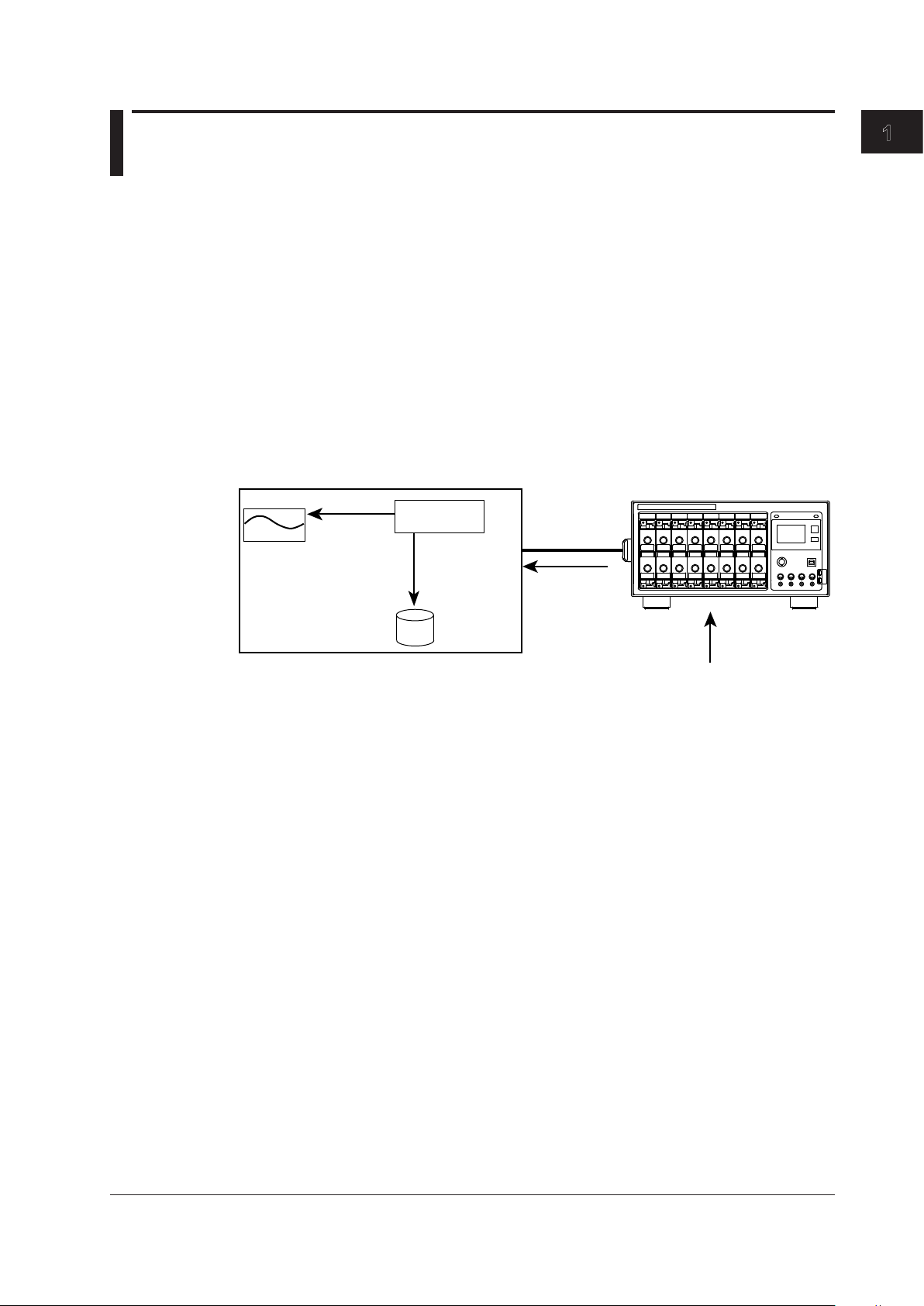
1.1 Overview of This Software
The Acquisition Software is used to connect to an SL1000 via the USB interface or the
optional Ethernet interface and record and display data that the SL1000 has measured.
The Acquisition Software allows you to do the following:
• Set measurement and record conditions of an SL1000.
• Start and stop measurements on an SL1000.
• Start and stop recording.
• Display waveforms of the measured data, cursor values, and waveform parameters.
• Synchronize the operation of up to eight linked SL1000s.
• Start the Xviewer (accompanying software) and display waveforms of data saved in
the past (excluding the /XV0 option)
Signal and Data Flow
The signal and data flow between this software and the SL1000 is described below.
Display
Display data
Measured raw data
Current value data
Communication
process
Measured raw data
HDD
Display data
Measured raw data
Current value data
Measurement file
1
What the Acquisition Software Can Do
SL1000
Display Data
P-P compression data that the SL1000 creates for displaying waveforms. The data is
sent to your PC in unit of measuring groups. For a description of display groups, see
section 1.5.
Measured Raw Data
All the measured data that the SL1000 acquired. The data is sent to your PC in unit of
measuring groups to save the data on the hard disk of your PC. For a description of
measuring groups, see section 1.2.
The data is used in data analysis such as cursor measurements and waveform
parameter computations.
Current Value Data
The current values that the SL1000 calculated. The data is sent immediately upon a
request from your PC.
IM 720120-61E
1-1
Page 11
PC
Signal to be measured
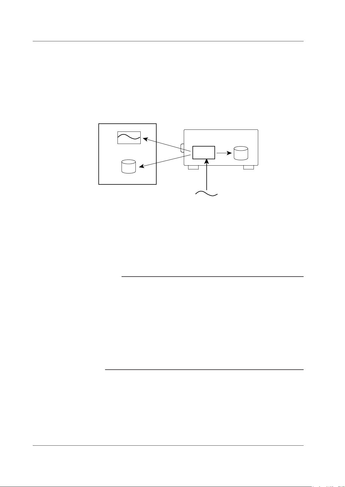
1.1 Overview of This Software
Measurement and Recording
This software refers to the task of acquiring measured data into the internal memory of
an SL1000 as measurement and the task of saving the measured data that has been
acquired to the internal memory of an SL1000 as files on your PC’s hard disk or the
internal hard disk of an SL1000 while making measurements as recording.
The measured data acquired in the internal memory of an SL1000 is cleared when the
power is turn ON/OFF or when measurement is resumed. The waveform screen of this
software displays waveforms of measured data acquired to the internal memory of an
SL1000 after applying P-P compression.
After the measurement stops, all the measured data acquired in the internal memory of
an SL1000 can be saved as a single file on your PC. This task is referred to as saving
not recording in which data is saved while the measurement is in progress.
Connecting to an SL1000
The USB can be used to connect your PC directly to an SL1000 or the optional Ethernet
interface can be used to connect to an SL1000 over the network.
Only a single SL1000 can be connected to a single PC.
Note
• Remove the USB or Ethernet cable that is connecting the SL1000 to the PC only after you
have exited the Acquisition Software or after you have disconnected the communication
between the SL1000 and the PC.
• In the default setting of the SL1000, the DHCP function is turned ON. You can immediately
connect an SL1000 to your PC by connecting the SL1000 to a network with a DHCP server.
• An exclusive driver is necessary to connect using the USB. If an SL1000 is connected
to your PC via the USB, an installation wizard starts. Install the driver according to the
instructions on the screen. For details, see section 2.3, “Installing the USB Driver.”
• You cannot connect both Ethernet and USB interfaces simultaneously to an SL1000.
You cannot connect to the SL1000 that this software is connected to via USB, using the
accompanying Xviewer (excluding /XV0) application nor using FTP.
• When connecting an SL1000 to the PC, disable the PC standby mode. If it is enabled, the
connection between the SL1000 and the PC may be disconnected.
Display
HDD
Record
Memory
SL1000
Record
HDD
Measure
1-2
IM 720120-61E
Page 12
Trigger sources and alarm sources can be combined between units (using AND or OR logic).
1.1 Overview of This Software
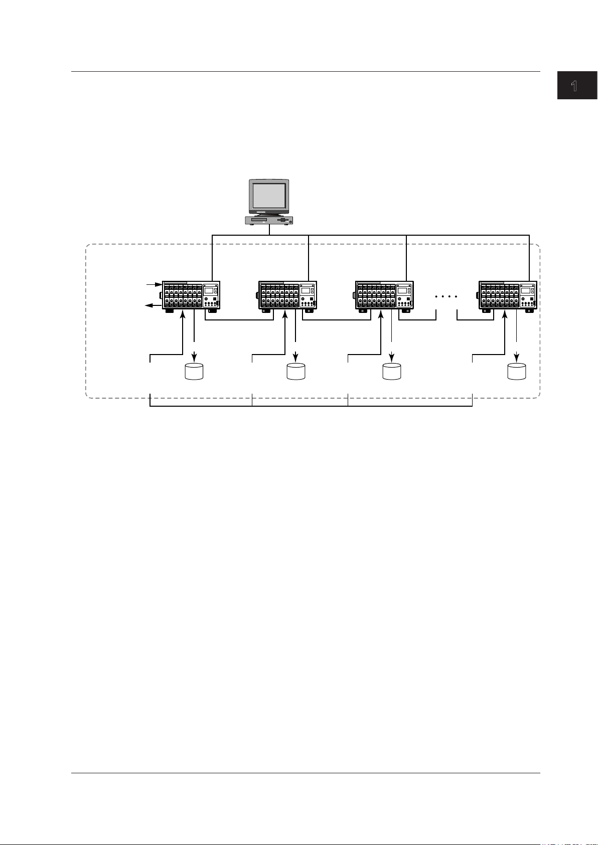
Synchronous Operation
You can synchronize the operation of up to eight SL1000s by connecting them using
the following synchronous connecting cable that are sold separately: 720901-01 (1 m in
length) or 720901-02 (3 m in length).
For instructions on how to connect the SL1000s to your PC for synchronous operation
and for details on the sync I/O connectors (SYNC IN and SYNC OUT), see the SL1000
High-Speed Data Acquisition Unit User’s Manual (IM 720120-01E).
Same GROUP ID (0 to F)
• External clock input
• External trigger
input
• Trigger output
• Alarm output
Signal input
(Trigger source,
Alarm source)
Master
UNIT-ID = 0
SYNC
OUT
HDD HDD HDD HDD
PC
Slave #1
UNIT-ID = 1
SYNC
IN
Signal input
(Trigger source,
Alarm source)
USB/Ethernet
SYNC
OUT
Signal input
(Trigger source,
Alarm source)
Slave #2
UNIT-ID = 2
SYNC
IN
SYNC
OUT
1
What the Acquisition Software Can Do
Slave #7
UNIT-ID = 7
SYNC
IN
RecordRecordRecordRecord
Signal input
(Trigger source,
Alarm source)
The external clock input and external trigger input synchronize with the signals from the
master unit. Trigger sources and alarm sources are combined using AND or OR logic
between units, and are transmitted from the master unit’s trigger output and alarm output.
The slave units’ external clock input, external trigger input, trigger output, and alarm
output are invalid.
Synchronized Items
• Measurement and recording start and stop
• Clock
Slave units synchronize to the master unit’s external or internal clock.
• Time (The time of the slave unit is synchronized with the time of the master unit.)
• Triggering
The AND or OR logic of the master unit’s external trigger input and slave units’ trigger
sources.
When the SL1000 triggers, the trigger signal is transmitted from the master unit’s
trigger output.
• Alarms
The AND or OR logic of the slave units’ channel alarm conditions or the OR logic of
the slave units’ system alarm conditions.
When an alarm occurs, an alarm signal is transmitted from the master unit’s alarm
output.
• Detection of sync cable disconnection and of units powering-off
IM 720120-61E
1-3
Page 13
Set the repeat conditions (for Free Run mode, sections 5.1 to 5.4)
1.1 Overview of This Software
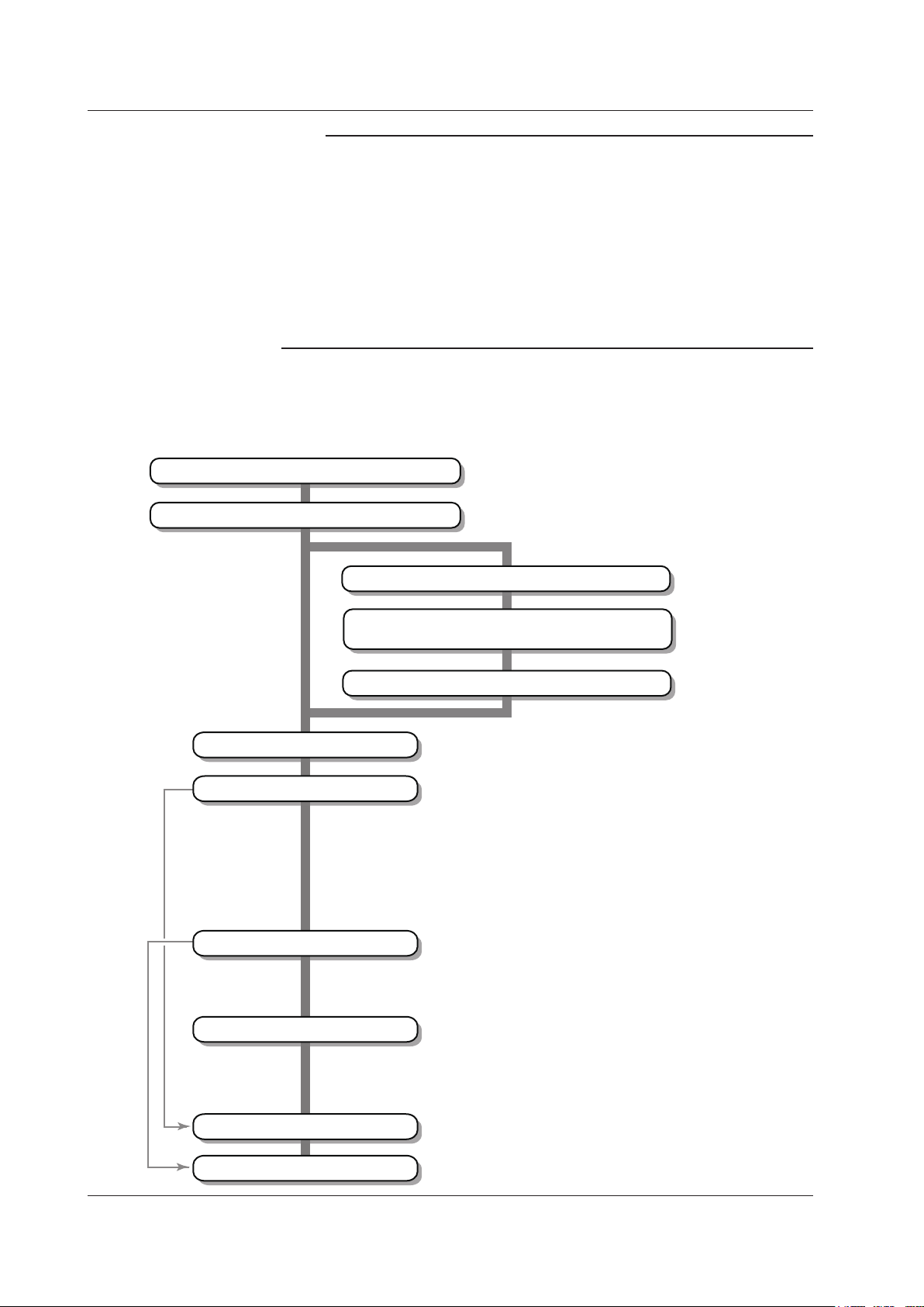
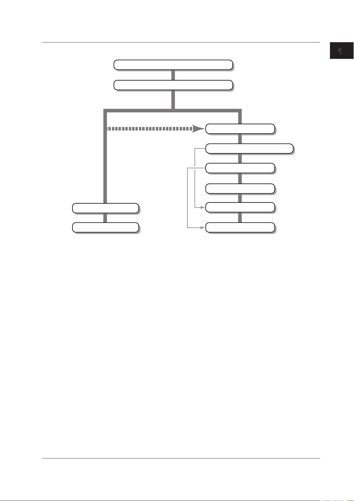
Workflow
The workflow to make measurements using the Acquisition Software varies depending
on whether it is the first time that you are connecting to the SL1000.
If Connecting to the SL1000 for the First Time
Note
• You cannot specify Single (N) of Triggered Mode.
• You cannot set the auto recording destination to PC HDD+Unit HDD.
• You cannot set the GO/NO-GO judgment output.
• When the save destination is set to Unit HDD, the recording files are saved to each unit’s
hard disk.
• To perform synchronous operation, set the master and slave units to the same group ID (from
0 to F). Set the master unit’s unit ID to 0, and slave units’ unit IDs in ascending order from
1 to 7. For details, see section 4.1 in the SL1000 High-Speed Data Acquisition Unit User’s
Manual (IM 720120-01E).
• Connect or disconnect the synchronous connecting cable only after (1) you have exited the
Acquisition Software or disconnected the communication between the SL1000 and PC and (2)
you have turn the SL1000 off.
Connect to the SL1000 via the USB
Install the USB driver
Connect via the USB
Set the communication parameters (TCP/IP)
Set the connection method to Ethernet on
the Connection & Group Settings screen
Connect to the SL1000 via the Ethernet network
Configure the system
Set the measurement conditions
Set the record conditions
(IM 720120-01E, a separate manual)
(section 2.3)
Connect via the Ethernet network (option)
(section 3.2)
(section 3.4)
(IM 720120-01E, a separate manual)
Set the measuring group
(Register the channels that will acquire measured data)
Set the measuring mode (section 4.1)
Set the acquisition mode (sections 4.1 and 4.8)
Set the clock source (sections 4.1 and 4.7)
Set the sample rate and sample interval (sections 4.2 to 4.6)
Set the measuring range, input coupling, and the like
(section 4.2 to 4.6)
Set the external clock (section 4.7)
Set the trigger (section 4.8)
Set the alarm (section 4.9)
Set GO/NO-GO (section 4.10)
Set the recording destination (chapter 5)
Set the recording start/stop conditions
(for Free Run mode, sections 5.1 to 5.4)
1-4
Set the display conditions
Start measurement
Start recording
Set file information (chapter 5)
Set the display group (section 6.1)
(Register the channels to be displayed on a waveform screen)
Set the scale (section 6.1)
Set the zone (section 6.1)
Set the waveform color and thickness (section 6.1)
Set the vertical and horizontal axes (section 6.1)
IM 720120-61E
Page 14
(IM 720120-01E, a separate manual)
1.1 Overview of This Software
If Reconnecting to the SL1000
Connect to the SL1000
Start the Acquisition Software
When the SL1000 is started with the
previous setup file (section 9.3)
Change the settings as necessary
Start measurement
1
What the Acquisition Software Can Do
(section 2.2)
When making measurements by changing
the measurement conditions
Configure the system
Set the measurement conditions
Set the record conditions
Set the display conditions
Start measurement
Start recording
* For details on each setup item, see the operation flow diagram “Connecting to the SL1000 for
the First Time.”
Start recording
IM 720120-61E
1-5
Page 15
1.1 Overview of This Software
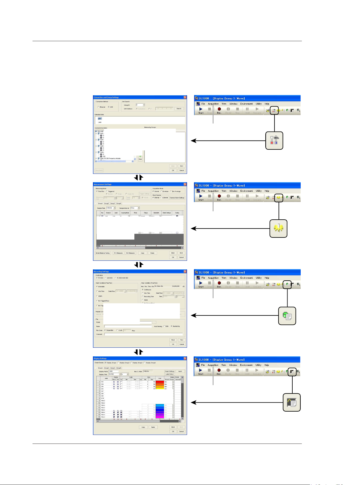
Setup in Wizard Format
The basic setup consisting of connection and group settings, measurement settings,
recording settings, and display settings can be specified easily using dialog boxes in
wizard format. You can also specify the connection and group settings, measurement
settings, recording settings, and display settings individually using the toolbar or menu
bar.
Acquisition menu
Connection & Group
Settings screen
For the operating procedure,
see chapter 3.
[NEXT]
[Back]
Acquisition menu
Measurement Settings screen
For the operating procedure,
see chapter 4.
[NEXT]
[Back]
Acquisition menu
Recording Settings screen
For the operating procedure,
see chapter 5.
1-6
[NEXT]
[Back]
Display Settings screen
For the operating procedure,
see chapter 6.
Acquisition menu
IM 720120-61E
Page 16
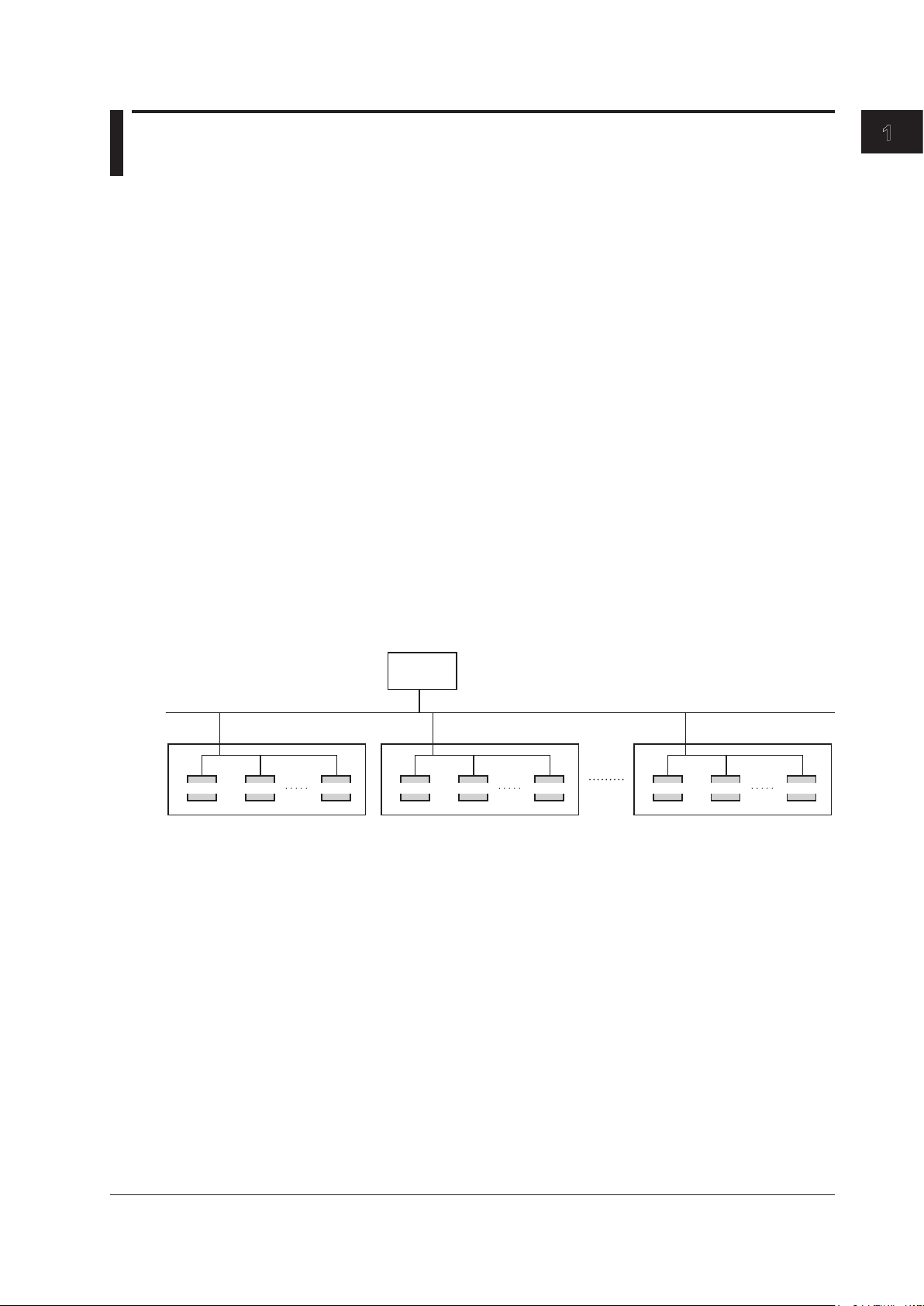
1.2 Connection & Group Settings
Unit ID = 0 Unit ID = 1 Unit ID = 7 Unit ID = 0 Unit ID = 1 Unit ID = 7 Unit ID = 0 Unit ID = 1 Unit ID = 7
Connection Method
Select USB or Ethernet for the interface used to communicate the SL1000. This software
can communicate with the SL1000 that is connected to the selected interface.
The Ethernet interface can be used on an SL1000 with the /C10 option.
Searching for an SL1000
Search for an SL1000 that is to communicate with your PC.
If connected using the USB, you can search for an SL1000 by specifying a group ID.
If connected using the Ethernet interface, you can search by specifying a group ID and
IP address.
Group ID
A number assigned to the SL1000. Group IDs are used to identify different SL1000s
connected to the network.
There are 16 group IDs: 0 to 9 and A to F.
You can also search for an SL1000 without specifying a group ID.
To perform synchronous operation, set the master and slave units to the same group ID.
Unit ID
A number assigned to the SL1000.
The unit ID cannot be specified when searching.
To perform synchronous operation, set the unit ID of the master unit to 0, and the unit ID
of the slave units to 1 to 7 in ascending order.
1
What the Acquisition Software Can Do
PC
USB/Ethernet
Group ID = 0 Group ID = 1 Group ID = F
SL1000 SL1000 SL1000
master
slave slave
master
slave slave
SL1000 SL1000 SL1000SL1000 SL1000 SL1000
master
slave slave
For details on the group ID and unit ID, see the SL1000 High-Speed Data Acquisition
Unit User’s Manual (IM 720120-01E).
IP Address
You can search by specifying an IP address assigned to the SL1000.
IM 720120-61E
1-7
Page 17
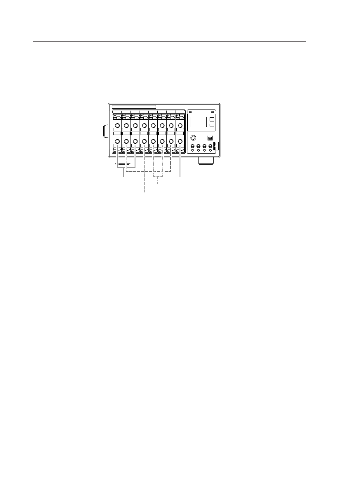
SL1000
Measuring group 1
Measuring group 2
1.2 Connection & Group Settings
Measuring Groups
Modules installed in a connected SL1000 are registered to measuring groups according
to the sample rate used to make measurements. Up to four measuring groups can be set
up.
Measurement is performed only on modules that are registered to measuring groups.
Below is an example of how modules can be registered to measuring groups.
Measuring group 4
Measuring group 3
1-8
IM 720120-61E
Page 18
1.3 Measurement Settings
Normal mode
Envelope mode
Measurement points at the maximum sample rate of the module
Maximum value
Measuring Mode
There are two measuring modes: Free Run and Triggered.
Free Run Mode
Data is acquired immediately upon starting a measurement. The SL1000 continues to
acquire data until the measurement is stopped.
The measured data can also be recorded to the hard disk of the SL1000 or your PC at a
specified time or when an alarm occurs.
The following functions are not available in Free Run mode.
• GO/NO-GO function
• Automated measurement of waveform parameters
• Zoom on a particular section of the waveform
Triggered Mode
After starting the measurement, the SL1000 acquires data when a trigger condition is
met. After acquiring data over the specified measuring time, data acquisition stops. You
can also record the measured data acquired in Triggered Mode to the hard disk of the
SL1000 or your PC.
If Triggered Mode is used, you can perform automated measurement of waveform
parameters and zoom in on waveforms.
For details on triggers, see section 1.6, “Triggering.”
The following functions are not available in Triggered Mode.
• Channel alarm
• Recording start and end condition settings
1
What the Acquisition Software Can Do
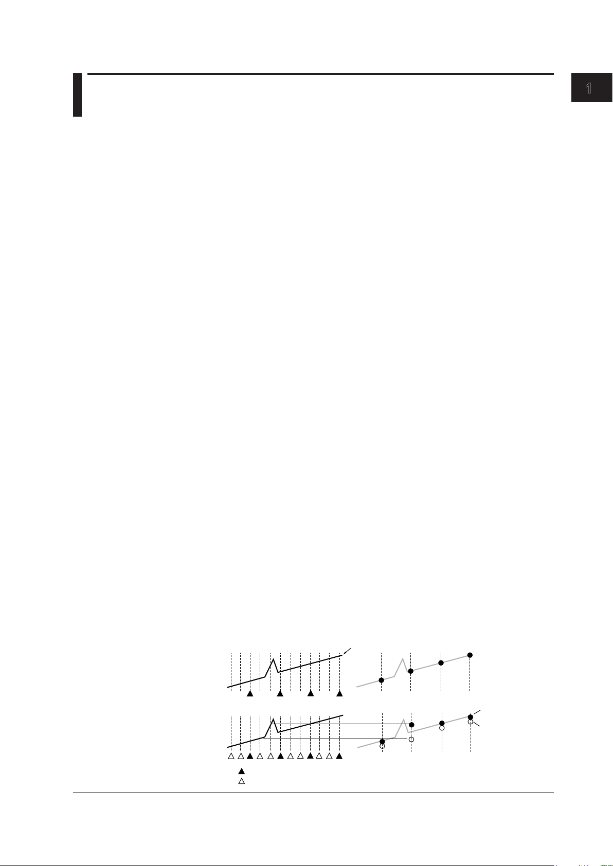
Acquisition Mode
Normal Mode
Envelope Mode
When acquiring measured data in the internal memory of the SL1000, it is possible to
perform processing on data and display waveforms based on the processed data. The
following three types of data processing are available.
In this mode, measured data is acquired without special processing.
If measuring at a sample rate lower than the maximum sampling rate of each input
module, the SL1000 samples data at 100 S/s internally, determines the maximum and
minimum values among the measured values over each sample interval at the specified
sample rate, and acquires them as pairs.
This mode is effective when you want to avoid aliasing because the sample rate is
essentially kept high. It is also effective when you want to detect glitches (pulse signals
which rise very fast) or display an envelope of a modulating signal.
Input signal
B
A
b
a
Minimum value
IM 720120-61E
Measurement points at the specified sample rate
1-9
Page 19
Time
Input signal (500 kS/s)
Box averaged data
1.3 Measurement Settings
Box Average Mode
Input modules with a maximum sample rate less than 100 MS/s cannot acquire data
at certain points even if the internal sampling rate is 100 MS/s. The data at points that
cannot be sampled will take on the same value as the previous measured data.
Envelope Mode has no effect if measuring at a sample rate higher than the maximum
sample rate of the input module.
This mode is available on the 701250 (HS10M12), 701255 (NONISO_10M12), 720210
(HS100M12), 720211 (HS100M12), and 720250 (HS10M12). In this mode, the SL1000
determines the moving average of the data sampled at the maximum sample rate and
acquires and displays the resultant data. Box averaging is effective in eliminating small
amounts of noise from the input signal. It can also remove noise from a single-shot
signal.
Clock Source
Internal Clock
The sampling timing of the measured data is controlled using the clock signal (internal
clock) that is generated from the internal time-base circuit of the SL1000.
External Clock
The sampling timing of the measured data is controlled using a clock signal applied
externally. This mode is available when the acquisition mode is set to Normal.
The external clock input is useful for observing a signal whose period varies or for
observing waveforms by synchronizing to the clock signal of the signal being measured.
The maximum frequency that can be used for the external clock varies depending on the
module.
720210, 720211: 5 MHz
701250, 701251, 701255, 720250: 1 MHz
701267, 701270, 701271, 701275: 100 kHz
701281, 720281, 720268: 1 MHz
701261, 701262: 100 kHz when measuring voltage
500 Hz when measuring temperature
701265, 720266: 500 Hz
If an external clock that exceeds the maximum frequency is applied, the data is sampled
at the maximum frequency, and the measured data at times when data cannot be
sampled is set to the same value as the previous sampled data.
When using an external clock, the time axis unit becomes the number of measured
points, not time. Therefore, the measuring time is set and the cursor measurement
values are displayed in terms of the number of measured points.
Voltage
Voltage
• • • •
21
20
• • •
2
• • • •
1
•
a
36
• • • •
Time
b
1-10
IM 720120-61E
Page 20

sample rate of the module
Data that is not actually acquired
Aliasing signal Input signal Sampling point
1.3 Measurement Settings
Sample Rate and Sample Interval
You can set the sample rate or sample interval for each measuring group.
The sample rate (the number of samples per second in unit of S/s) is related to the
sample interval as follows:
Sample rate = 1/sample interval
The maximum sample rate varies depending on the module. If you set a sample rate that
exceeds the maximum sample rate of a module, data cannot be acquired at the specified
sample rate. The data at times when data cannot be acquired is set to the same value as
the previous acquired data.
Note
If the sample rate of measuring group 1 is set to 50 MS/s, 5 MS/s, 500 kS/s, 50 kS/s, 5 kS/s,
500 S/s, or 50 S/s, the sample rate of other groups cannot be set to the next lower sample rate.
For example, if the sample rate of measuring group 1 is set to 500 kS/s, the sample rate of
other measuring groups cannot be set to 200 kS/s (the next lower sample rate).
1
What the Acquisition Software Can Do
Input signal
Measured data
Data that is actually acquired
Sampling timing at the specified
sample rate
Sampling timing at the maximum
The SL1000 can display waveforms correctly for frequencies less than one-half the
sample rate as defined by the Nyquist sampling theorem.*
* If the sample rate is comparatively low with respect to the input signal frequency,
the harmonics contained in the signal are lost. In this case, some of the harmonics
will appear at low frequencies due to the effects described by the Nyquist sampling
theorem. This phenomenon is called aliasing. You can avoid aliasing by acquiring
waveforms with the acquisition mode set to envelope.
IM 720120-61E
1-11
Page 21

terminal
DC AC GND
terminal
DC-RMS AC-RMS
1.3 Measurement Settings
Input Coupling
If you want to measure only the amplitude of an AC signal, measurement is easier if the
DC component is removed from the input signal. On the other hand, there are times
when you want to check the ground level or measure the entire input signal (both the DC
and AC components). You can change the input coupling setting to meet your application
needs. By changing this setting, the way in which the vertical control circuit (voltage axis)
receives the input signal is switched. The following types of input coupling are available.
DC
The input signal is directly coupled to the attenuator of the vertical control circuit. Select
DC if you want to measure the entire input signal (DC and AC components).
AC (Only When Measuring the AC Voltage)
The input signal is coupled to the attenuator of the vertical control circuit through
a capacitor. Select AC if you want to measure only the amplitude of the AC signal,
eliminating the DC components from the input signal.
GND
Input signal is coupled to the ground not to the attenuator of the vertical control circuit.
Select GND to check the ground level on the screen.
Input
1 MΩ
Vertical
control
circuit
Input
terminal
1 MΩ
Vertical
control
circuit
Input
terminal
Vertical
control
circuit
TC (Only When Measuring the Temperature)
Select TC if you are measuring the temperature using the 701261 (UNIVERSAL), 701262
(UNIVERSAL (AAF)), 701265 (TEMP/HPV), or 720266 (TEMP/HPV).
DC-RMS
Using the 701267 (HV (with RMS)) or 720268 (HV (with RMS/AAF)), both the DC and AC
components of the signal are converted to rms values and displayed. An RMS conversion
circuit is connected to the vertical control circuit of the same input coupling circuit used
when the coupling is set to DC.
AC-RMS
Using the 701267 (HV (with RMS)) or 720268 (HV (with RMS/AAF)), only the AC
component of the signal is converted to rms values and displayed. An RMS conversion
circuit is connected to the vertical control circuit of the same input coupling circuit used
when the coupling is set to AC.
Input
1 MΩ
Vertical
control
circuit
RMS
conversion
circuit
AD
Input
terminal
1 MΩ
Vertical
control
circuit
RMS
conversion
circuit
AD
ACCL (Only When Measuring Acceleration)
Select ACCL when measuring acceleration on the 701275 (ACCL/VOLT).
1-12
IM 720120-61E
Page 22

1.3 Measurement Settings
Probe Attenuation and Current-to-Voltage Conversion Ratio
For voltage (current) measurement, a probe is normally used in connecting the circuit
being measured to the signal input terminal. Using a probe has the following advantages.
• Prevents disturbing the voltage and current of the circuit being measured.
• Applies the signal with no distortion.
• Expands the measurable voltage (current) range of the SL1000.
When using a probe, the attenuation setting on the SL1000 must be set equal to the
probe attenuation or current-to-voltage conversion ratio so that the measured voltage
(current) can be read directly.
Set the probe attenuation for the accessory probes (sold separately) as follows:
• Isolated probe (700929): 10:1
• Current probe (700937 and 701933): 10 A:1 V
• Current probe (701930 and 701931): 100 A:1 V
• 10:1 Passive Probe for the DL750/DL750P (701940): 10:1
The SL1000 has the following attenuation settings: 1:1, 10:1, 100:1, 1000:1, 1 A:1 V,
10 A:1 V,
accessories (sold separately), set the attenuation ratio on the SL1000 according to the
attenuation of the probe.
2
and 100 A:1 V.3 If you are using a probe other than the ones provided as
1 Output voltage rate: 1 V/A
2 Output voltage rate: 0.1 V/A
3 Output voltage rate: 0.01 V/A
1
What the Acquisition Software Can Do
1
Measuring Range
Bandwidth Limit
Note
Use a probe that matches the input capacity of each module. Otherwise, the capacity cannot
be adjusted.
Set the measuring range according to the input signal.
Select a TC type when measuring temperature.
You can set a upper bandwidth limit on the analog signal for each channel. This allows
you to observe waveforms with noise components above the specified frequency
removed.
IM 720120-61E
1-13
Page 23
Measured value
Scale value
Ground level or
strain balance level
Normal display Inverted display
1.3 Measurement Settings
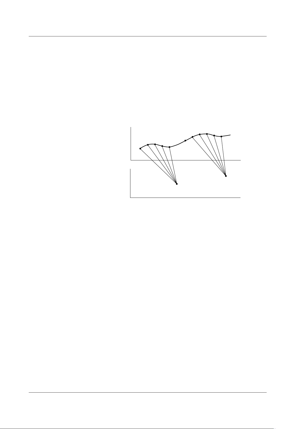
Linear Scaling
The measured data can be scaled to any physical value and displayed.
When measuring the voltage (current), strain, or frequency (number of rotations, period,
duty cycle, power supply frequency, pulse width, pulse integration, and velocity), there
are two methods of linear scaling: “aX+b” and “P1-P2.”
aX+b
The results obtained from the following computation based on the specified scaling
coefficient a and offset b are displayed as cursor measurement values and automated
measurement values of waveform parameters. You can also assign a unit to the result of
linear scaling.
Y = aX + b
P1-P2
Specify arbitrary scale values (P1Y and P2Y) for the measured values of two arbitrary
points (P1X and P2X). The scale conversion equation (y = ax + b) is derived from these
four values.
• Range of measured values (P1X and P2X): –9.99990E+25 to +9.99990E+25
• Range of scaled values (P1Y and P2Y): –9.99990E+25 to +9.99990E+25
• Initial setting of scale values: P1X +0.0000E+00, P1Y +0.0000E+00
P2X +1.0000E+00, P2Y +1.0000E+00
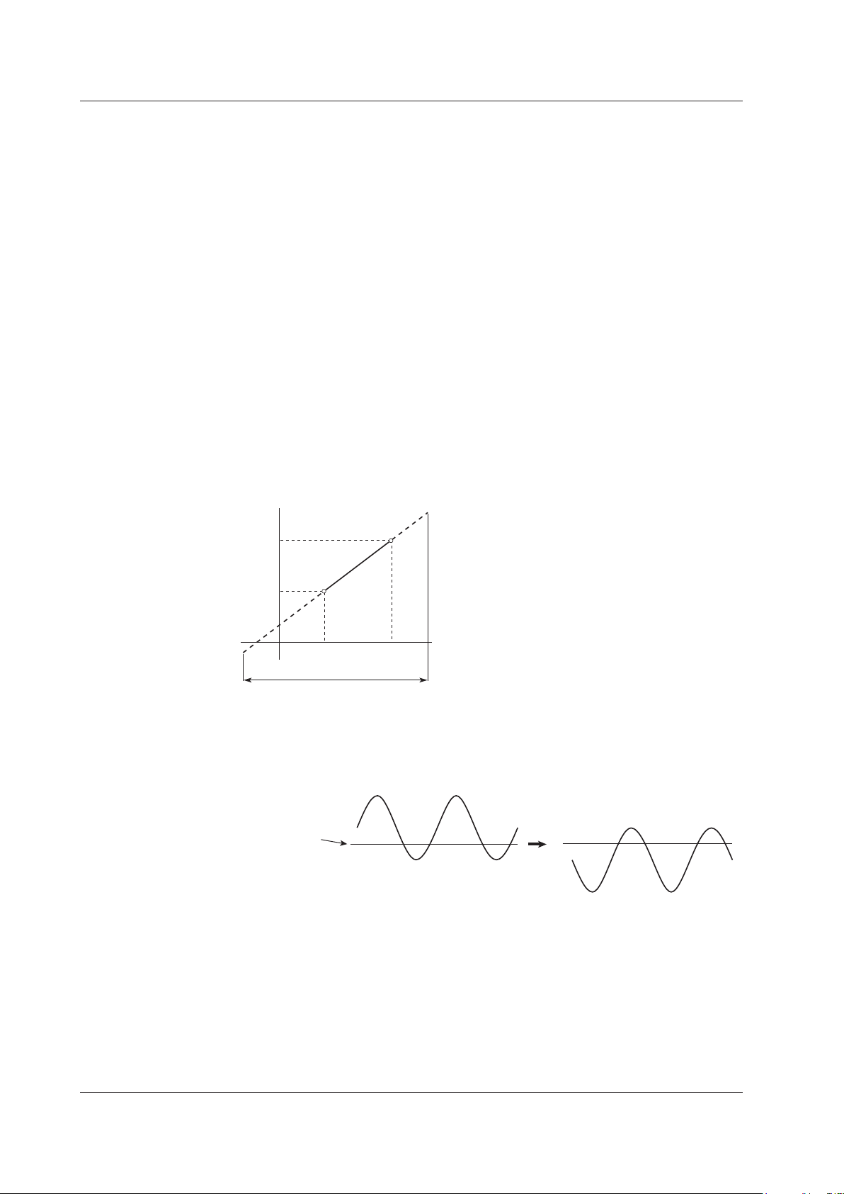
Inversion
y = ax + b
P2Y
P1Y
P1
P1X
Measuring range
P2
P2X
When measuring voltage or strain, the waveform can be displayed with the vertical axis
inverted around the ground level or the strain balance level as shown below.
1-14
IM 720120-61E
Page 24
0
where u(t) is the input signal and T is one period of the input signal.
V
0
V
0
2
1.3 Measurement Settings
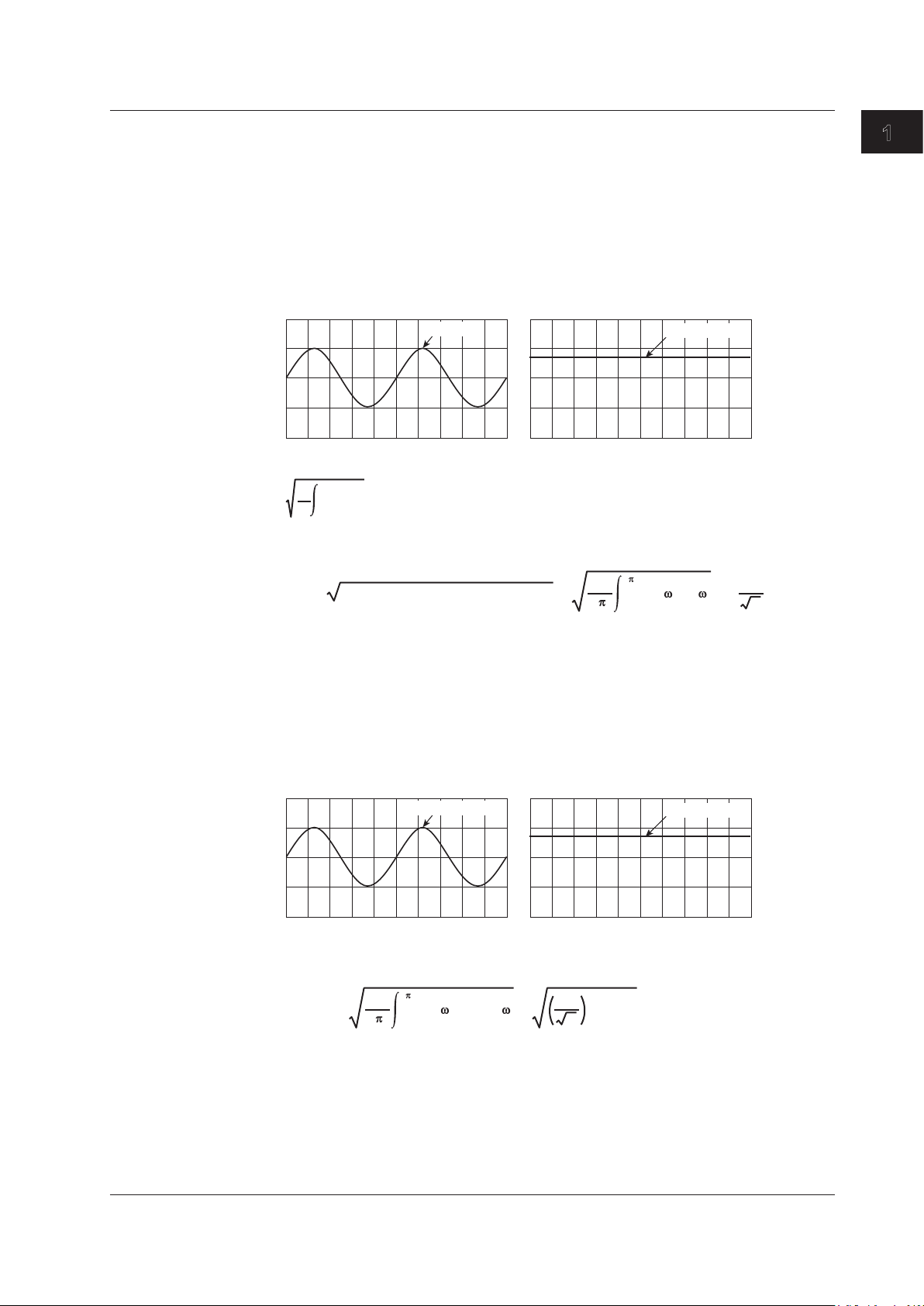
RMS Measurement
If the module is 701267 (HV (with RMS)) or 720268 (HV (with RMS/AAF)), you can
observer the RMS value of the input signal.
AC-RMS
This setting is used when you want to observe only the rms values of the AC signal,
eliminating the DC components from the input signal.
Example
If the rms value of a 2-Vpeak sinusoid input signal is measured, a DC waveform at
approximately 1.4 V is displayed (see right figure).
2 Vpeak
Approx. 1.4 V
The rms value is derived from the following equation:
T
1
u(t)2 dt
T
Givenu(t)=VmsinωtwhereVmisthepeakvalue,ωistheangularvelocity(whichis
equal to 2pf where f is the frequency of the sinusoid signal), the rms value, Vrms, is
2
rms
The average of u(t)2 over one cycle
=
1
= =
(Vmsin t)2 d t
2
Vm
2
1
What the Acquisition Software Can Do
As in the above example, when Vm is 2 V, the rms value, Vrms, is approximately 1.4 V.
DC-RMS
This setting is used when you want to observe the rms values of both the DC and AC
components of the input signal.
Example
If the rms value of a 2-Vpeak sinusoid input signal riding on top of a 1-V DC component
is measured, a DC waveform at approximately 1.7 V is displayed (see right figure).
2 Vpeak + 1 Vdc
Approx. 1.7 V
IftheDCcomponentisexpressedasVdcandtheACcomponentasu(t)=Vmsinωt,the
rms value, Vrms (+DC), of the sinusoid input signal riding on top of the DC component is
derived from the following equation:
2
rms(+DC)
1
= =
(Vmsin t+Vdc)2 d t
2
Vm
2
dc)
(V
+
2
As in the above example, when Vdc is 1 V and Vm is 2 V, the rms value, Vrms (+DC), is
approximately 1.7 V.
IM 720120-61E
1-15
Page 25

1.3 Measurement Settings
Temperature Measurement
Thermocouple Type
The following types of thermocouples are available.
K, E, J, T, L, U, R, S, B, N, W, and Au7Fe
Selectable Temperature Units
You can select °C or K.
Reference Junction Compensation (RJC)
The voltage generated by a thermocouple depends on the temperature of the point of
measurement and the reference junction temperature. In this case, the function used
to compensate the temperature on the measurement instrument to the cold junction is
referred to as reference junction compensation.
You can turn ON/OFF the internal RJC circuit of the SL1000.
ON: Use this setting to enable the reference junction compensation by the internal
OFF: Select this setting when checking the temperature measurement value or when
Burnout
Specify the behavior when the thermocouple input detects a burnout.
ON: Fix the measured value to the upper limit of the measurement range of each
OFF: Not detect burnouts.
RJC circuit.
using an external reference junction (0 °C).
thermocouple if a burnout is detected.
1-16
IM 720120-61E
Page 26

1.3 Measurement Settings
Strain Measurement
You can measure strain by connecting a strain gauge bridge (bridge head) or a strain
gauge transducer to the strain module (701270 (STRAIN_NDIS) or 701271 (STRAIN_
DSUB)).
Relationship between the Strain (μSTR) and the Transducer Output (mV/V)
TheSL1000allowstheunittobechangedbetween“thestrainunit(μSTR:×10
and “the output unit of the strain gauge transducer (mV/V)
(μSTR).”ThefollowingrelationshipexistsbetweenμSTRandmV/V.
(mV/V)=0.5×(μSTR)/1000
Example
500(μSTR)→0.5×500(μSTR)/1000=0.25(mV/V)
Gauge Factor If mV/V Is Selected
K = 2
You can set the gauge factor to any value on the SL1000. However, if there are no
specifications on the strain gauge transducer, set K to 2.
If K is not 2, e is derived in the SL1000 using the following equation.
e=(4/K)×(V/E)
If you switch the unit, the unit of all related parameters of the channel is switched
accordingly.
• Scale
• Trigger level
• Values of automated measurement of waveform parameters and cursor
In addition, the 701271 (STRAIN_DSUB) supports shunt calibration.
For a description of the basic defining equation of strain and shunt calibration, see the
SL1000 High-Speed Data Acquisition Unit User’s Manual (IM 720120-01E)
–6
1
.” The default setting is “strain
e: Measured value of the strain gauge transducer [mV/V]
V: Voltage measured on the bridge [V]
E: Voltage applied to the bridge [V]
K: Gauge factor
measurements, etc.
2
1 The unit corresponding to the output of the strain gauge transducer. A value expressing
the transducer output per volt applied to the bridge in mV. You can set the bridge voltage
(excitation: voltage applied to the bridge) from 2 V, 5 V, and 10 V on the SL1000. However,
since the mV/V value is a converted value, the measured value is basically constant.
2 Shunt calibration refers to the act of correcting the gain of the strain measurement by
connecting a known resistance (shunt calibration resistance) to the strain gauge in parallel.
1
What the Acquisition Software Can Do
strain)”
IM 720120-61E
1-17
Page 27

1.3 Measurement Settings
Acceleration Measurement
The Acceleration Module (with AAF) (701275 (ACCL/VOLT)) measures acceleration
using the output signal from an acceleration sensor. Direction connection is possible to
a built-in amplifier type acceleration sensor. (A charge output type acceleration sensor
that does not have a built-in amplifier cannot be connected directly to the 701275 (ACCL/
VOLT). For details on how to connect acceleration sensors, see the SL1000 High-Speed
Data Acquisition Unit User’s Manual (IM 720120-01E).)
Note
The 701275 (ACCL/VOLT) can also measure voltage.
Current Supply to Acceleration Sensors
The 701275 (ACCL/VOLT) can supply 4 mA of current to the acceleration sensor when
measuring acceleration.
Note
If you supply current to the acceleration sensor before it is connected to the item under
measurement, the internal circuit of the acceleration sensor may be damaged. Be sure to
supply current after connecting the acceleration sensor.
Filter
If you set the bandwidth limit to Auto, the anti-aliasing filter (AAF) and low-pass filter are
enabled depending on the sample rate to eliminate high-frequency noise from the input
signal. Using the anti-aliasing filter when measuring voltage allows elimination of aliasing
noise. For details on the bandwidth limit, see section 4.2.
Note
The filter is effective not only during acceleration measurement but also during voltage
measurement.
1-18
IM 720120-61E
Page 28
Tw(s)
F(Hz)
Nr: The number of
pulses per rotation
Tw(s)
Tw(s)
Thigh(s)
Tlow(s)
1.3 Measurement Settings
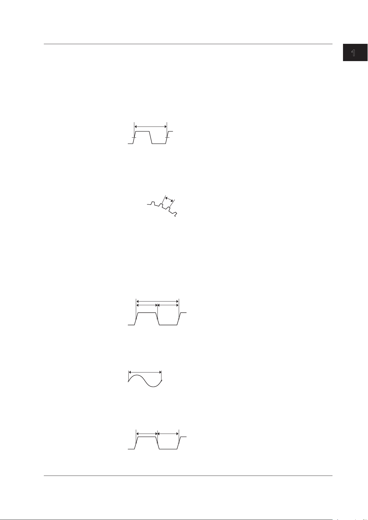
Frequency Measurement
The Frequency Module (701281 (FREQ) or 720281 (FREQ)) measures frequency,
number of rotations, period, duty cycle, power supply frequency, pulse width, pulse
integration, and velocity.
Measured Item
Frequency
Frequency F (Hz) = 1/Tw (s)
Measurable range: 0.01 Hz to 500 kHz
RPMs/RPSs
RPMs=Frequency(Hz)/thenumberofpulsesperrotation(Nr)×60
Measurable range: 0.01 rpm to 100000 rpm
RPSs = Frequency (Hz)/the number of pulses per rotation (Nr)
Measurable range: 0.001 rps to 2000 rps
1
What the Acquisition Software Can Do
Period
Period (s) = Tw (s)
Measurablerange: 2μsto50s
Duty
Duty cycle (%) = Thigh (s)/Tw (s) or
Duty cycle (%) = Tlow (s)/Tw (s)
Measurable range: 0% to 100%
Power Supply Frequency
Power supply frequency (Hz) = 1/Tw (s)
Resolution: 0.01 Hz
Measurable range: (50 Hz, 60 Hz, 400 Hz) ±20 Hz
Pulse Width
Pulse width (s) = Thigh (s) or
pulse width (s) = Tlow (s)
Measurablerange: 1μsto50s
Thigh(s)
Tlow(s)
IM 720120-61E
1-19
Page 29
N (count)
Tw(s)
Distance per
pulse (l)
Pulse input stop
Stop prediction
0
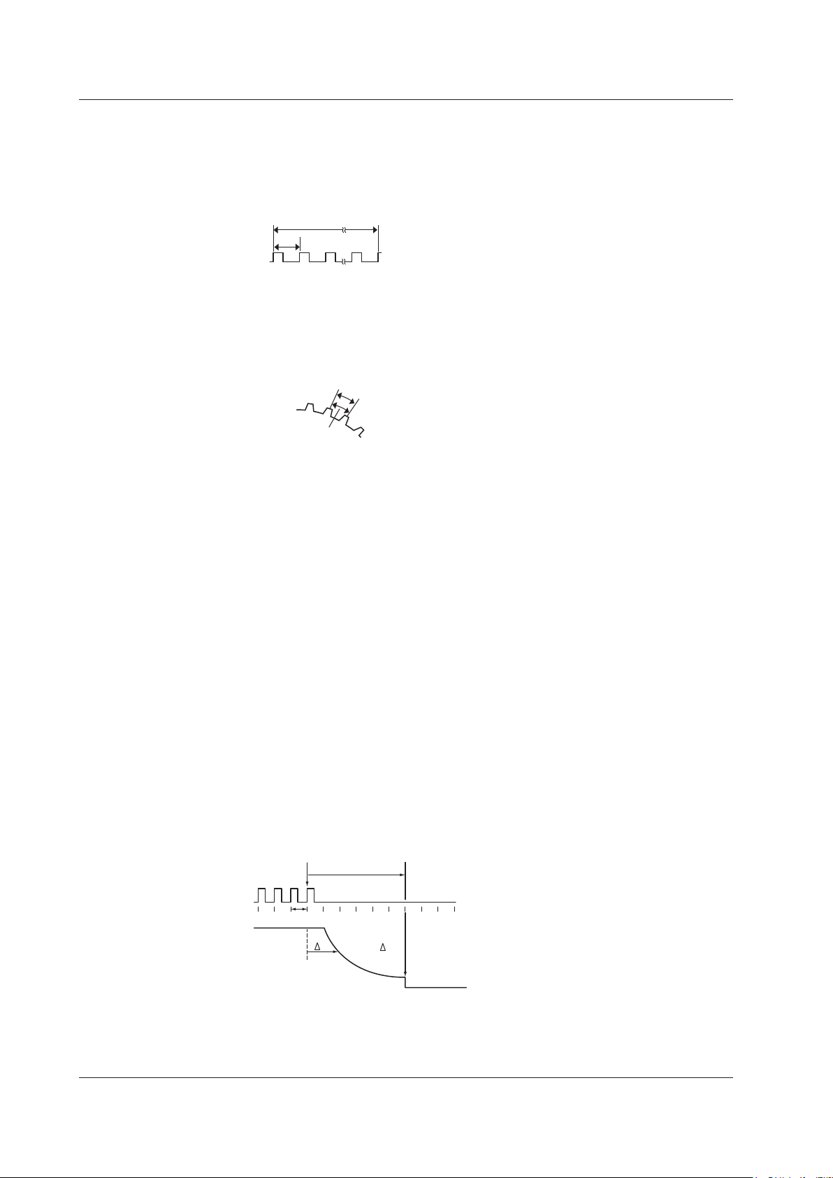
1.3 Measurement Settings
Pulse Integration (Distance/Flow Rate)
Pulseintegratedvalue=N(count)×physicalamountperpulse(I)
Set the physical amount per pulse (I) to distance or flow rate.
A suitable user-defined unit can be assigned to the specified physical amount.
Measurablerange: upto2×10
9
counts
Velocity
Velocity(km/h)=Distanceperpulsel(km)/Tw(s)×3600
Velocity (m/s) = Distance per pulse l (m)/Tw (s)
The distance and unit can be defined by the user (angular velocity, etc.).
Measurable range: F (=1/Tw) = 0.01 Hz to 500 kHz
Decelerating Prediction and Stop Prediction
The 701281 (FREQ) or 720281 (FREQ) automatically performs internal computation and
displays waveforms by predicting the deceleration curve and stop point even when the
input pulse is suddenly cut off. This function allows the measurement of waveforms of
deceleration behavior that is close to the actual physical phenomenon in applications in
which the deceleration behavior of an object that have inertia is measured such as in the
brake test of automobiles.
Decelerating Prediction
The deceleration curve is computed according to the following equation using the
elapsed time after the pulse input stops (Δt).
Frequency (f) = 1/period (Δt)
The decelerating prediction starts after a pulse period (T) of the pulse one period
before the pulse input stopped elapses after the pulse input stopped.
l
Stop Prediction
The function determines the stop point at a constant time after the pulse input stops,
and the frequency is set to 0. The time from the point when the pulse input stops to
thepointwhenthefunctiondeterminesthattheobjecthasstoppedcanbesetto×1.5,
×2,×3,...,×9,and×10(10settings)ofthepulseperiod(T)ofthepulseoneperiod
before the pulse input stopped.
1-20
T×n
n: 1.5 to 10
T
f0
Decelerating
prediction
t
f = 1/ t
IM 720120-61E
Page 30
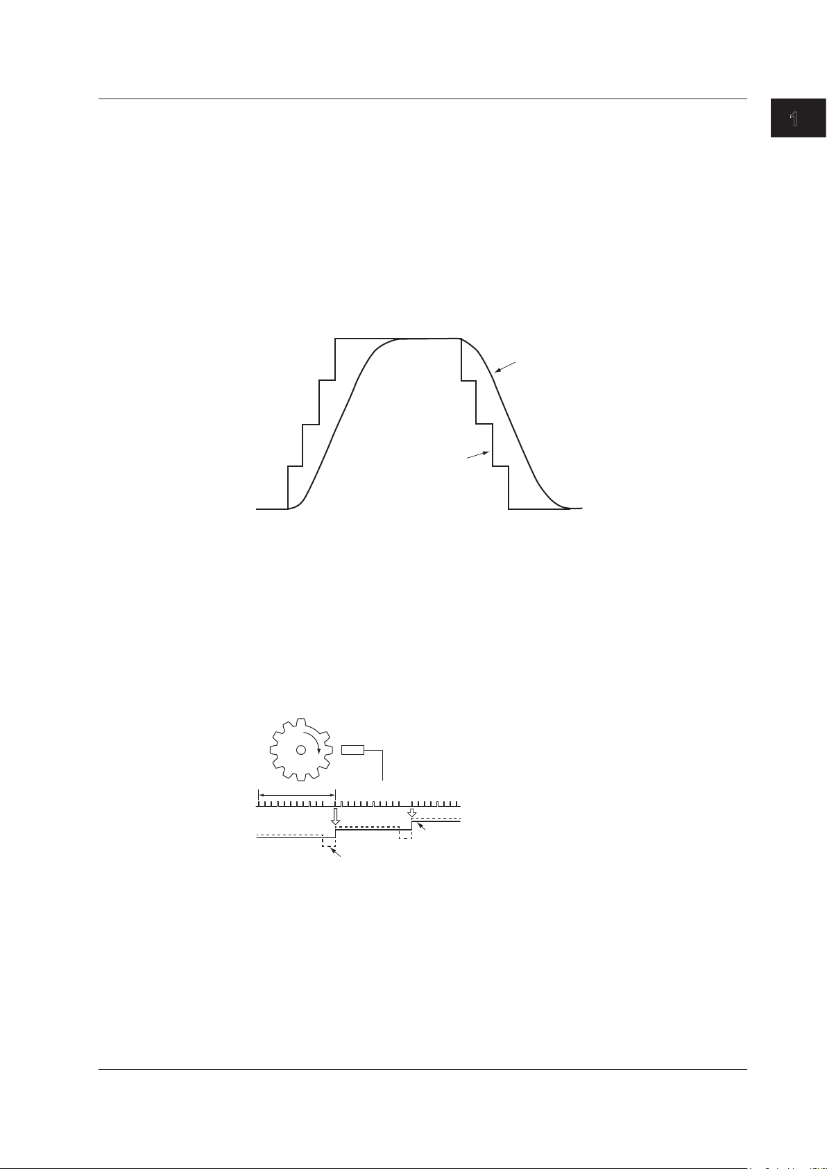
If the smoothing filter is used
If pulse average is used
If pulse average is not used
1.3 Measurement Settings
Filter
Smoothing filter (moving average)
The frequency module can display waveforms by taking the moving average of the data
in realtime. The order of moving average can be set in terms of time in the range of 0.0 ms
to 1 s (up to 25000th order). The order of moving average is equal to the specified time
dividedby40μs.
The smoothing filter has the following characteristics.
• Converts a waveform that changes in steps to a smooth waveform.
• Improves the resolution by reducing the measurement jitter. The resolution improves
especially when measuring high frequencies or when expanding the display using the
offset function. Consequently, highly accurate measurements can be made.
• Can be used on all measurement parameters of the frequency module.
Original waveform
1
What the Acquisition Software Can Do
Pulse Average
Measures the input pulse by dividing the pulse by the specified number of pulses (1 to
4096 pulses). The pulse average has the following characteristics.
• If pulse dropouts are present or pulse interval is fluctuating within a period,
measurements can be made by eliminating the effects from the dropout or fluctuation
(fluctuating component of the waveform used to measure the frequency or period).
• The measured result is displayed as a value per input pulse even when pulse average
is used. Therefore, there is no need to perform scaling again.
• Can be used when measuring frequency, number of rotations, period, power supply
frequency, pulse integration, and velocity.
N = 11
f1
f2
f3
Offset Function
The 701281 (FREQ) or 720281 (FREQ) allows you to set the center of observation (offset
value) and expand the area around the offset value for close observation. It allows you to
measure the fluctuation around a certain frequency. You can set an offset value up to 100
times the measuring range (500 kHz maximum).
IM 720120-61E
1-21
Page 31

1.4 Recording Settings
Recording Methods
There are two recording methods. One method is to record automatically according to
the specified conditions (auto recording). The other method is to save the measured
data that has been acquired in the memory of the SL1000 through file operation after the
measurement is finished (saving of waveform data).
Auto Recording
The measured data is automatically recorded to a specified hard disk.
You can select the recording destination from the following three destinations:
• PC HDD: Records to the hard disk of the PC in which this software was installed.
• Unit HDD: Records to the hard disk of the SL1000.
• PC HDD+Unit HDD: Records both to the hard disk of your PC and to the hard disk of
the SL1000.
The free space on the hard disk of your PC and the SL1000 can be displayed on the
screen.
Note
During synchronous operation, you cannot select PC HDD+Unit HDD.
Saving the Waveform Data
The measured data acquired in the internal memory of the SL1000 is saved to your PC.
All the measured data in the memory is saved as a single file.
The data saved to the hard disk of the SL1000 can be copied to the hard disk of your
PC using the accompanying Xviewer (except the /XV0 option) or the FTP function (/C10
option).
Averaging and Saving History Data
The measured data acquired in the internal memory of the SL1000 is averaged and
saved to your PC. From the measured data in the memory, you select the data (up to
5000 waveforms) to average, and the data is saved as a single file.
The saved averaged waveforms can also be displayed on the screen using the
accompanying Xviewer (except the /XV0 option).
Recording Start and Stop Conditions (Auto Recording)
The recording start and stop conditions vary depending on the measuring mode.
In Free Run Mode
You can select the following recording start and stop conditions.
Recording start condition
Immediate: Starts recording as soon as it is ready to record.
Abs.Time: Starts recording at a specified time if it is ready to record.
Alarm: Starts recording when an alarm occurs if it is ready to record.
External trigger: Starts recording when the SL1000 is ready to record and it receives
a recording control signal (edge signal or gate signal) through the
trigger input terminal. (Rise) indicates rising edge trigger, and (Fall)
indicates falling edge trigger.
* The SL1000 will be ready to record if you click the Start Recording button or choose
Start Recording from the Acquisition menu.
1-22
IM 720120-61E
Page 32

1.4 Recording Settings
Recording stop condition
Continuous: Continues to record until recording is manually stopped.
Abs.Time: Continues to record to a specified time.
Recording time: Continues to record for a specified time. When measuring with an
external clock, measurement is performed up to a specified number
of measured points.
Alarm: Continues to record until the alarm is cleared.
External trigger: Stops recording when the SL1000 receives a recording control signal
(edge signal or gate signal) through the trigger input terminal. (Rise)
indicates rising edge trigger, and (Fall) indicates falling edge trigger.
In Trigger Mode
The SL1000 will start measuring or recording if the trigger conditions are met when the
SL1000 is ready to record.
recording will stop. The SL1000 can also start measuring or recording after a given time
elapses from when the trigger condition is met.
* The SL1000 will be ready to record if you click the Start Recording button or choose
Start Recording from the Acquisition menu.
Repeat Condition (Auto Recording)
When recording the measured data repetitively, you can specify the repeat count and the
repeat interval.
*
When a specified measuring time arrives, measurement and
1
What the Acquisition Software Can Do
Record Interval
The record interval can be specified only if the recording start condition is set to
Immediate or Abs. Time and the recording stop condition is Recording Time. You can
specify the time (the number of measured points if measuring using an external clock
signal) from when the recording is started until the next recording is started. This is
available when the measuring mode is set to Free Run.
Record Count
The number of recordings. You can set it if
• The recording stop condition is set to Recording time.
• The recording start and stop conditions are set to Alarm.
• The recording start and end conditions are both External Trigger (Rise) or both
External Trigger (Fall).
The record count is valid when the measuring mode is set to Free Run.
IM 720120-61E
1-23
Page 33

ACQ Start
ACQ Stop
Measurement
state
Record state
Records the measured data
ACQ Start
ACQ Stop
Recording start condition met
Recording stop condition met
Measurement
state
Record state
ACQ Start
ACQ Stop
Recording start condition met
Recording stop condition met
Measurement
state
Record state
1.4 Recording Settings
Relationship between Measurement and Recording (Auto Recording)
Free Run Mode
The recording of the measured data is enabled when measurement is in progress.
Examples of the measurement state, recording start and stop conditions, and repeat
conditions are given below.
If Recording Start Condition Is Immediate and Recording Stop Condition Is
Continuous
Measurement in progress
Recording Start and Stop Conditions Other Than Those Above
If Recording Is Stopped before the Recording Stop Condition Is Met
Rec Start
Rec Start
Rec Start
Recordable
Measurement in progress
Recordable
Records the measured data
Measurement in progress
Recordable
Records the measured data
Rec Stop
Rec Stop
1-24
IM 720120-61E
Page 34

condition met
•
• If repeat interval is set for the repeat condition
(If the recording start condition is set to Immediate or Abs. Time and the recording stop
ACQ Start
ACQ Stop
Trigger condition met
Measurement
state
Record state
1.4 Recording Settings
Relationship with the Repeat Condition
1
What the Acquisition Software Can Do
condition is Recording Time)
ACQ Stop
Rec Stop
Recording start
condition met
Recording stop
condition met
ACQ Stop
Rec Stop
Recording start
condition met
Recording stop
Measurement
state
Record state
ACQ Start
Rec Start
Records the
measured data
Measurement in progress
Recordable
Record interval
Records the
measured data
If repeat interval is not set for the repeat condition
Measurement
state
Record state
ACQ Start
Rec Start
Records the
measured data
Measurement in progress
Recordable
Records the
measured data
Note
To record measured data continuously, set the interval of the repeat condition to OFF when the
recording start condition is set to Immediate or Abs.Time and the recording stop condition is
set to Recording Time.
Triggered Mode
Measurement and recording are performed for a specified time if a trigger occurs when
the SL1000 is ready to measure and record.
If a trigger occurs when the SL1000 is not ready to record, only measurement is
performed.
Rec Start
Measures/records
over the specified time
Measurable
Recordable
Measures/records
over the specified time
Rec Stop
IM 720120-61E
1-25
Page 35

In Free Run Mode
Sequence number when a single file
Year
Hour
Character string
In Triggered Mode
In Free Run Mode
Sequence number when a single file exceeds 2 GB (000 to 999)
Year
Day
Sequence number (000 to 999)
20070630_000 (June 30, 2007)
1.4 Recording Settings
File Name and Recording Destination
To Use the Date/Time in the File Name
The date/time (ms unit) of the recording is used for the file name. An arbitrary file name
cannot be specified.
20070630_121530_100_000 (2007/06/30 12:15:30.100)
Year
Month
Day
In Triggered Mode
20070630_121530_100 (2007/06/30 12:15:30.100)
Month
Day
To Use a Sequence Number in the File Name
A sequence number is added to a file name that you specify.
exceeds 2 GB (000 to 999)
ms
Second
Minute
Hour
ms
Second
Minute
File Order
TEST0000_000
Sequence number (0000 to 9999)
Character string
TEST0000
Sequence number (0000 to 9999)
Recording Destination
When recording to the hard disk of your PC, you can specify the save destination folder.
This software creates a folder with the following name within the specified folder and
saves the data.
Month
There are two methods for recording measured data to the hard disk of your PC or the
SL1000: sequential and cyclic.
Sequential
Records the files sequentially to the hard disk. This method is useful if you want to retain
the old data. If the number of recordings is large, the free space on the hard disk may run
out.
Cyclic
Records the specified number of files. If the specified number is exceeded, the file is
overwritten in order from the oldest one. This method is useful if the free space on the
hard disk is low.
1-26
IM 720120-61E
Page 36

1.5 Display Settings
0
100
Display Group
The data measured on measuring channels that are registered to measuring groups
can be divided into four groups (display groups) to be displayed. Channels of different
measuring groups can be registered in a same display group. A single group can contain
up to 16 channels (up to 128 channels when eight units are linked during synchronous
operation). The same channel can also be registered to multiple groups.
The measured data of channels in the same group (display group 1) can be compared
using cursor values and values obtained through automated measurement of waveform
parameters.
Note
If the maximum sample rate among the measuring channels registered to a single display group
is 50 MS/s, 5 MS/s, 500 kS/s, 50 kS/s, 5 kS/s, 500 S/s, or 50 S/s, a measurement channel with
the next lower sample rate cannot be registered to the same display group. For example, if the
maximum sample rate among the channels registered to a display group is 500 kS/s, a channel
with the sample rate set to 200 kS/s (the next lower sample rate) cannot be registered to the
same group.
Scale
You can set the display range. If linear scaling is set on the channel, the range is
specified using a scaled value.
It is also possible to automatically set a scale based on the measured data.
1
What the Acquisition Software Can Do
Zone
You can set the position to display the waveform.
The display position is set in terms of a percentage of the screen.
This feature keeps waveforms from overlapping when displaying multiple waveforms on
a single screen.
The following example shows the case when the display zone of waveform A is set to
30% to 100% and that of waveform B is set to 0% to 70%.
A
B
Displays Other Than Waveforms
Current Value Display
The current measured value is displayed using a bar graph, digital display (numeric),
analog meter, or thermometer.
Current values are measured data that this software retrieves from the SL1000 at 100ms intervals (Free Run mode) or 1-s intervals (Triggered mode).
Numeric Value Display
Displays the measured values at the cursor position, waveform parameter values
(measure value), and GO/NO-GO judgment result.
70
30
IM 720120-61E
1-27
Page 37

1.6 Triggering
Normal mode
Single (N) mode
and trigger timing.
Trigger Mode
The trigger mode defines the method in which measured data is acquired when a trigger
occurs. The following three modes are available.
Single Mode
When a trigger occurs, the SL1000 acquires measured data once for the specified
measuring time. This mode is suitable for observing a single-shot signal.
Normal Mode
The SL1000 acquires measured data each time a trigger occurs. After acquiring data for
the specified number of times, the SL1000 stops the acquisition. If the acquisition count
is set to infinite, data acquisition continues until the measurement is stopped.
After acquiring the measured data as a result of trigger occurrence, the SL1000 does not
accept the next trigger until the internal processing of the data is completed.
Single (N) Mode
The SL1000 acquires measured data each time a trigger occurs. You can select whether
to acquire the data the specified number of times and stop or acquire data infinite times.
The SL1000 acquires measured data whenever a trigger occurs even if the internal
processing of data is not completed.
If the acquisition count is specified, the maximum number of acquisitions is 5000 or
the number of acquisitions determined by the number of channels, sample rate, and
measuring time, whichever is less.
Note
During synchronous operation, you cannot select Single (N) mode.
Trigger
Data acquisition Data transmission/recording
Memory
Data acquisition and data transfer/recording are synchronous.
Trigger
Data acquisition Data acquisitionData acquisition Data acquisition
Memory Memory Memory Memory
(Dead time)
PC HDD
Waveform display
PC HDD
Waveform display*
Data acquisition Data transmission/recording
Memory
PC HDD PC HDD
Waveform display* Waveform display*
(Dead time)
PC HDD
Waveform display
1-28
Data transmission/recording
Data acquisition and data transfer/recording are asynchronous.
*: The software may not be able to display the acquired data, depending on the internal processing time
Data transmission/recording Data transmission/recording
IM 720120-61E
Page 38

Specified date/time
1.6 Triggering
Trigger Class
Trigger Source
The following two trigger classes are available.
Simple
A trigger is generated on a single trigger condition.
Combination
A trigger occurs when all or any of the multiple trigger conditions are met. Combination is
valid if the trigger sources are channels.
The following three trigger sources are available.
Channel
Generates a trigger on an input signal or the external trigger signal. A trigger can be
generated on a combination of trigger sources consisting of multiple channels and
external trigger signal.
Line
Generates a trigger on the rising edge of the power signal that is being supplied to the
SL1000. Waveforms synchronized to the commercial power supply frequency (50 Hz or
60 Hz) can be observed.
Time
Generates a trigger at specified time intervals (1 min to 24 hours) from a specified time.
1
What the Acquisition Software Can Do
Trigger generated Trigger generated Trigger generated
Specified time
IM 720120-61E
1-29
Page 39
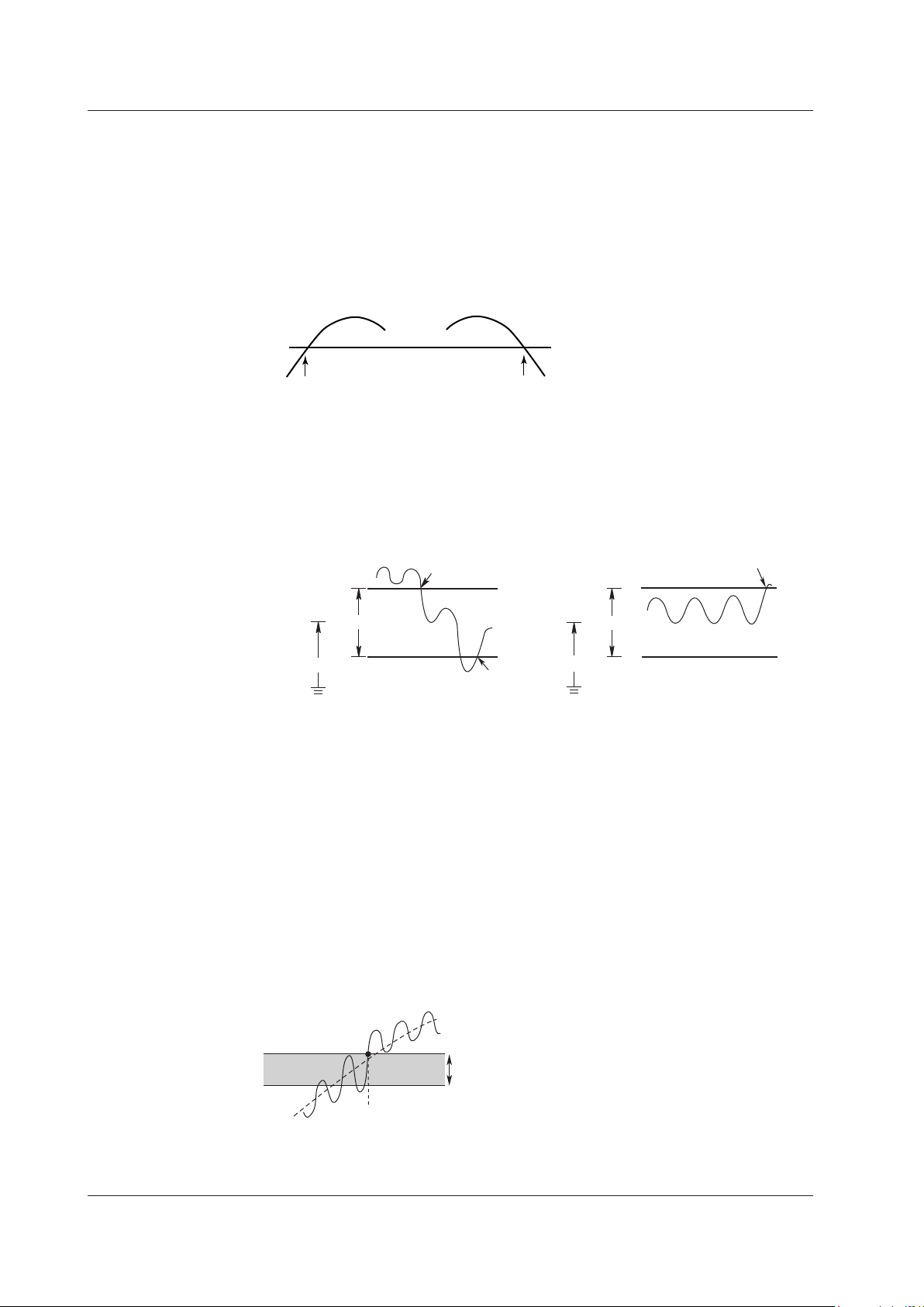
Trigger generated
Rising edge
Trigger generated
Trigger level
Falling edge
Trigger generated
OUT
IN
Trigger generated
Trigger level
Trigger generated
Hysteresis width
1.6 Triggering
Trigger Pattern, Trigger Level, and Hysteresis
Trigger Pattern
Select Rise (rising edge), Fall (falling edge), Both (both rising and falling edges), H (high),
L (low), IN, OUT, IN (L), or OUT (L).
Rise (Rising Edge), Fall (Falling Edge), and Both (Both Rising and Falling Edges)
A trigger is generated when the trigger source level becomes greater than or equal to
the trigger level; less than or equal to the trigger level; or both.
H (High) and L (Low)
A trigger is generated when the trigger source level is greater than or equal to the
trigger level (H) or less than or equal to the trigger level (L).
IN/OUT
A certain level width (window) is set and a trigger is generated when the trigger source
level enters this level width (IN) or exits from this level width (OUT).
Window width
IN(L)/OUT(L)
A certain level width (window) is set and a trigger is generated when the trigger source
level is within this level width (IN (L)) or outside this level width (OUT (L)).
Trigger Level
Trigger level refers to the level that is used to determine the trigger pattern (rising/falling
edge of the signal) and the like.
Hysteresis
If there is insufficient trigger level width such as when noise is present in the trigger
source, the trigger point fluctuates each time a trigger is generated. This causes the
displayed waveforms to be unstable. To solve this problem, a specified margin (trigger
hysteresis) is added to the trigger level. You can set the trigger hysteresis to Low (small
hysteresis width), Middle (medium hysteresis width), or High (large hysteresis width). The
hysteresis width varies depending on the input module.
Trigger generated
Window width
Trigger level
1-30
IM 720120-61E
Page 40

Trigger point
Trigger position
If the trigger pattern is set to rising edge
1.6 Triggering
Pre-trigger, Trigger Delay, and Hold Off
Trigger Point and Trigger Position
Trigger point refers to the point where a trigger is generated. Trigger position refers to the
position where measurement is started after a trigger is generated. Normally, the trigger
point and the trigger position are the same. However, if you set a trigger delay (explained
later), the trigger position will be after the trigger point by the delay amount.
Pre-trigger
The section before the trigger positions is called pre-trigger section. Waveforms before
the trigger position can be displayed by measuring the pre-trigger section.
Specify the pre-trigger section as a percentage of the measuring time. If measuring using
an external clock, specify the pre-trigger section as a percentage of the number of data
points.
Trigger Delay
Setting a trigger delay allows displaying of waveforms that are acquired a specified time
(delay) after the trigger is generated. The function is invalid if the trigger source is set to
Time or if the SL1000 is measuring using an external clock.
The selectable range of trigger delay is 0 to 10 s.
Delay
1
What the Acquisition Software Can Do
Hold Off
Hold off refers to the act of temporarily stopping the detection of the next trigger once a
trigger has been generated. This function is useful when observing a pulse train signal,
such as a PCM code, and you want to acquire the waveform in sync with the repeat
interval as shown below. The function is invalid if the trigger source is set to Time or if the
SL1000 is measuring using an external clock.
The selectable hold off range is 0 to 10 s.
Trigger level
Input signal
Pre-trigger
Measuring time
Repetition period
Hold off time
Measuring time
Invalid trigger
Measuring time
Trigger Trigger
IM 720120-61E
Acquired waveform
1-31
Page 41

1.6 Triggering
Recording of Measured Data in Triggered Mode
If measuring in Triggered Mode, the recording start and stop conditions of measured data
as explained in section 1.4 are invalid. Measured data is recorded to the specified hard
disk each time a trigger occurs after recording is started. When the measurement caused
by a specified trigger stops, recording also stops.
Manual Trigger
After starting the measurement, data can be acquired at any time by pressing the manual
trigger button.
This function is available only when the measuring mode is set to Triggered Mode.
1-32
IM 720120-61E
Page 42

1.7 Analysis Function
For waveforms with low sample rate For waveforms with high sample rate
Cursor target
Cursor target
waveform
there is not measured data
Under shoot: (Low – Min)/(High – Low) × 100 [%]
Over shoot: (Max – High)/(High – Low) × 100 [%]
P-P: P-P value (Max – Min) [V]
(Peak to peak value)
Max:
(Maximum)
Min:
(Minimum)
RMS:
Average:
Standard deviation:
Cursor Measurement
There are two types of cursors: horizontal cursors and vertical cursors. Two cursors are
displayed for each type of cursor. The measured values at the two cursor positions and
the difference between the cursors can be displayed.
You can move the cursor directly by dragging it or by using the left and right arrow keys
on the keyboard. If you are dragging the cursor, the cursor moves in steps of screen
dots.
If you are using the left and right arrow keys, the vertical cursor moves over the
measured data. The speed at which the cursor moves varies depending on the number
of measured data points displayed on the screen.
If the number of measured data points is greater than the number of dots on the
waveform screen, the cursor moves on all the measured data points that are displayed at
the dot before moving to the next dot. Therefore, the cursor will move slower.
If multiple waveforms with different sample rates are displayed on the same screen, the
cursor moves according to the sample rate of the cursor target waveform.
1
What the Acquisition Software Can Do
Waveform Parameter Measurements
Cursor movement
Measured value that cannot
be read with cursors
Cursor movement
Displays the same value as the
previous measured value because
If measuring in Triggered Mode, the following parameters can be measured automatically.
Voltage Axis Parameters
*
Maximum voltage [V]
*
Minimum voltage [V]
*
RMS value { (xi)2}
Average voltage xi [V]
Over shoot
Under shoot
2
xi
{ – ( )
n
1
n
xi
2}1/2
n
1
n
[V]
1/2
P-P
High: High voltage [V]
Low: Low voltage [V]
Amplitude: (High – Low) [V]
Middle: (Max + Min)/2
[V]
* The characters inside the parentheses are
measurement item names used when displaying the
measured values.
Max
Min
High
Low
waveform
IM 720120-61E
1-33
Page 43

Rise Fall
Rise: Rise time [s]
Fall
Freq
Period
Avg Freq
(Average frequency)
Avg Period: Average period within the measuring range [s]
Pulse count
For Pulse = 3
Proximal line (10%)
T1 T2
Proximal line (10%)
Burst1, Burst2: Burst width [s]
T1 T2
Int2TY
Int1TY
Total area for positive side only: S1 + S2
1.7 Analysis Function
Time Axis Parameters
: Fall time [s]
: Frequency [Hz] 1/Period
: Period [s]
: Average frequency within
the measuring range [Hz]
+Width –Width
Measuring
range
*
Period
Distal line (90%)
Mesial line (50%)
(Average period)
+Width: Time width above the mesial value [s]
(Plus width)
–Width: Time width below the mesial value [s]
(Minus width)
*
*
*
Duty: Duty cycle + Width/Period × 100[%]
* The characters inside the parentheses are measurement
item names used when displaying the measured values.
High (100%)
Distal line (90%)
Mesial line (50%)
Proximal line (10%)
Low (0%)
1-34
Distal line (90%)
Mesial line (50%)
Burst2
Burst1
Measuring
range
Other Parameters
Int1TY: The area under the positive amplitude
Int2TY: The area under the positive amplitude – the area under the negative
amplitude
Total area for both positive and
negative sides: S1 + S3 – S2
S1
S2
S1
S2
S3
IM 720120-61E
Page 44

1.8 Alarms
OUT(L)
IN(L)
Alarm occurrence Alarm occurrence
Alarm level 1
Alarm level 2
There are two types of alarms: channel alarm and system alarm.
Channel Alarm (for Free Run Mode)
An alarm is generated when the measured data meets a specified condition.
Source Channels
The alarm source can be set to any channel registered in a measuring group. You
can also specify multiple channels for the source and make the alarm go off when all
channels meet the condition (AND) or when any channel meets the condition (OR).
Alarm Patterns
There are 4 alarm patterns.
H: An alarm is generated when the measured value of the source channel is
greater than a specified level.
L: An alarm is generated when the measured value of the source channel is less
than a specified level.
IN(L): An alarm is generated when the measured value of the source channel is
within a specified range.
OUT(L): An alarm is generated when the measured value of the source channel is
outside a specified range.
1
What the Acquisition Software Can Do
Hysteresis
System Alarm
Alarm level 1
Alarm level 2
Like triggers, a certain width (hysteresis) can be set on the alarm level. You can select
the hysteresis from Low, Middle, and High.
When a system error occurs, the SL1000 transmits an alarm signal from the rear-panel
alarm terminal. You can set an alarm that combines multiple system alarms.
The following errors are detected.
HDD Full: An alarm is generated if the hard disk for recording the
measured data runs out.
Acq Memory Overrun: An alarm is generated if the memory buffer acquiring the
measured data overruns during auto recording.
Fan Stop: An alarm is generated if the cooling fan of the SL1000 stops.
Sync. Failure Detection: An alarm is generated when a synchronous connecting
cable is disconnected during synchronous operation.
System alarms are always sent to the PC. The Acquisition Software displays a message
that describes the system alarm details and also displays the details in the error
information area.
IM 720120-61E
1-35
Page 45

1.8 Alarms
Alarm Output
The terminal on the SL1000 rear panel can be used to transmit a TTL logic signal when
an alarm occurs. The SL1000 cannot transmit both the channel alarm and system alarm
simultaneously.
In the case of a channel alarm, the SL1000 can be configured so that the signal level
remains even when the alarm condition is cleared after an alarm occurrence (hold) or so
that the signal level is returned to the original level when the alarm condition is cleared
(nonhold).
In the case of a system alarm, the signal level remains even when the alarm condition is
cleared after an alarm occurrence (hold).
Alarms during synchronous operation are generated from the master SL1000 unit (whose
unit ID is zero).
Recording Start and Stop Conditions
An alarm occurrence can be used as a condition for starting or stopping the recording.
For details on recording, see section 1.4.
1-36
IM 720120-61E
Page 46

1.9 GO/NO-GO Judgment (for Triggered Mode)
GO/NO-GO judgment is performed on whether a value obtained through automated
measurement of waveform parameters is within a specified range. It is also possible to
execute an action such as data recording or buzzer based on the judgment result.
This function is useful if you want to inspect signals and track down abnormal symptoms
on an electronic equipment production line .
This function is available only when the measuring mode is set to Triggered Mode.
Note
You cannot configure GO/NO-GO judgment during synchronous operation.
Criteria
Specify upper and lower limits for each parameter. The SL1000 judges whether the
waveform parameter is within or outside the specified range. You can also specify
multiple waveform parameters (up to 16) and perform judgment when all conditions are
met (AND) or when any condition is met (OR).
The judgment area can be set to all the measured data that have been acquired or the
measured data between cursors.
Judgment Action
The following action can be executed based on the GO/NO-GO judgment result.
Save Data
Records the measured data in binary format to the hard disk specified in the recording
settings. Data is stored to a destination or file specified in Recording Settings.
1
What the Acquisition Software Can Do
Buzzer
Sounds the buzzer on the SL1000.
IM 720120-61E
1-37
Page 47

1.10 X-Y Display
You can view the correlation between two input signal levels by assigning the level of
a waveform to the X-axis (horizontal axis) and assigning the level of another waveform
to the Y-axis (vertical axis). X-Y waveforms are displayed in a different window from the
window that displays normal waveforms.
You can display up to four display groups of X-Y waveforms.
This feature is available on software versions 2.10 and later.
X-Axis and Y-Axis
X-Axis
Any channel registered in a measuring group can be assigned to the X-axis.
Y-Axis
Channels whose sample rate is the same as that of the X-axis and that have their
waveform display set to ON in their display condition settings are assigned to the Y-axis.
Number of Data Points to Draw
You can set the number of data points to draw to 2K, 10K, or 100K.
In Triggered Mode
If the number of measured data points is less than the specified number of data points to
draw, the SL1000 uses all the measured data to draw the waveform.
If the number of measured data points is greater than the specified number of data points
to draw, the SL1000 draws the waveform by reducing the number of data points to the
specified number. This reduction is done by taking the midpoint of the maximum and
minimum values of multiple measured data points.
The cursor measurement values are displayed using the measured raw data that is
stored internally.
Display Area
Note
• When displaying data measured in Triggered mode on the X-Y display, if the number
of measured data points is greater than the number of data points to draw, the SL1000
displays the waveform by taking the midpoint of maximum and minimum values of the
measured data points. When taking cursor measurements, the cursors may be displayed off
of the X-Y waveform because the cursors are displayed according to the measured data.
• If there are too many waveforms or too many data points drawn on the X-Y display, the
waveform display updating and waveform recording may slow down.
In Free Run Mode
If the number of measured data points is less than the specified number of data points to
draw, the SL1000 uses all the measured data to display the waveform.
If the number of measured data points is greater than the specified number of data points
to draw, the SL1000 displays as much of the most recent measured data as is specified
by the number of data points to draw.
In Triggered Mode
You can select the range of the X-Y display from the following.
Main: The X-Y display shows the measured data of normal waveforms.
Zoom: The X-Y display shows the measured data of zoomed waveforms.
In Free Run Mode
The X-Y display shows the measured data of normal waveforms.
1-38
IM 720120-61E
Page 48

1.11 Screen Description
Recording buffer
Waveform screen
Display group
Information about the hard disk of your PC or the internal hard disk of the SL1000
Main Screen
Menu bar
Toolbar
I/O state
Measurement
state
1
What the Acquisition Software Can Do
Record state Remaining hard disk indicator
Status bar
File information
Information about the Hard Disk of Your PC or the Internal Hard Disk of the SL1000
Displays information about the hard disk of your PC or the internal hard disk of the
SL1000. You can switch the displayed hard disk using tabs.
File Information
Displays the file name, save time, data size, and the like of the measured data or setup
data that are saved.
Record State
The lamp is red while recording to the hard disk.
Remaining Hard Disk Indicator
Displays the remaining hard disk space as Mbyte. If the remaining space falls low, the
bar turns red.
Measurement State
Displays the current measurement state such as Measuring, Wait Trigger, and Stop.
When the measuring time is greater than or equal to 1 s: Pre Trigger, Wait Trigger, Post
Trigger, and Stop
When the measuring time is less than 1 s: Wait Trigger, Measuring, and Stop
Recording Buffer
Displays a bar that indicates buffer usage. The closer the recording buffer usage gets
to overrunning the buffer, the longer the blue bar becomes. For example, this situation
occurs when recording cannot keep up with the measured data.
IM 720120-61E
1-39
Page 49

Changes the ratio of the
Adjusts the
brightness of the
waveform display area
(highlighted display)
1.10 Screen Description
I/O State
Waveform Screen
Over-Range
Turns red when an over-range occurs.
Double-click to display an over-range list screen showing a list of channels that overrange is occurring on.
Trigger Signal State
The lamp is yellow if the trigger condition is met or if an external trigger signal is being
applied.
Alarm Output State
The lamp is red while an alarm is being output.
Displays the master output state during synchronous operation.
GO/NO-GO Judgment Output State
The GO lamp is green if GO is being output. The NO-GO lamp is red if NO-GO is being
output.
Turns ON/OFF the zone display
Measurement count
Zone
Active waveform
Adjusts the grid
brightness
background
Turns ON/OFF the
waveform display
Active Waveform
The waveform with a triangle mark is the active waveform.
Scale
Displays the scale according to the display settings. If zones specified with overlapping
scales, the scale of the active waveform is displayed.
Measuring Mode
Displays “Free Run,” or the Trigger Mode’s “Normal,” “Single,” “Single (N).”
Scale
Maximum sample rateMeasuring Mode
Trigger positionTrigger level
Waveform display area Numeric value display area
For Free Run mode
waveform display area to
the numeric value display area
Expansion rate
Displays Main/Zoom
waveform
1-40
Maximum Sample Rate
Displays the measuring group 1 sample rate.
Adjusting the Trigger Position and Trigger Level
Drag the markers to set the trigger position and trigger level.
Adjusting the Brightness of the Grid (Graticule)
Drag the knob to change the brightness of the grid.
IM 720120-61E
Page 50

1.11 Screen Description
X-axis channel
Y-axis scale
X-axis scale
X-Y display range
Measuring mode
Adjusting the Background Brightness of the Waveform Display Area (Highlighted
Slide the knob to change the background of the waveform display from black to white in
steps
Turn ON/OFF the Waveform Display
Click this area to turn ON/OFF the channel display. Channels that are displayed are
indicated in light blue.
Turning ON/OFF the Zone Display (Sliding Window)
Move the pointer over this area and click when this area changes to light purple to turn
ON/OFF the zone display area.
Main Waveform or Zoom Waveform
The displayed waveform is indicated by the blue frame.
Changing the Ratio of the Waveform Display Area to the Cursor Value Display Area
Drag when the pointer changes to a left-right arrow to change the ratio of the display
areas.
Time Display
In Free Run mode, the displayed time range is displayed along with the elapsed time.
X-Y Waveform Screen
Display)
1
What the Acquisition Software Can Do
Number of data
points to draw
Maximum sample rate
Scale
The scale that you set in the respective display conditions is displayed for the X- and
Y-axes. If multiple channels are registered to the Y-axis, the scale of the active waveform
is displayed.
Measuring Mode
Displays “Free Run,” or the Trigger Mode’s “Normal,” “Single,” or “Single (N).”
Maximum Sample Rate
Displays the X-axis channel's sample rate.
IM 720120-61E
1-41
Page 51

Start Monitoring button
Recording Settings buttonMeasurement Settings button
Version display button
1.11 Screen Description
Menu Bar
File Menu
A menu used to save and load setup files, to save and load waveform data, to save
measured data, to load image data, to transfer files, and so on.
Acquisition Menu
A menu used to enter connection & group settings, measurement settings, trigger
settings, recording settings, display settings, alarm settings, GO/NO-GO settings, and
measure settings as well as execute auto setup, manual trigger, measurement start/stop,
recording start/stop/divide, and display hold/resume.
View Menu
A menu used to list alarm history, to show and hide operating information, to set
waveform zooming, to set waveform zones, to configure measured value display, to show
and hide instantaneous values, to show and hide full-screen display, to show and hide
the toolbar, and to show and hide the status bar.
Window Menu
A menu used to set the waveform screen. This menu appears when the waveform screen
is displayed.
Toolbar
Environment Menu
A menu used to enter environment settings and communication settings, perform a selftest, display the system information of the SL1000, enable the key lock on the SL1000,
initialize the SL1000, and calibrate the SL1000.
Utility Menu
A menu used to start the included Xviewer software (excluding models with the /XV0
option) and to start the File Utility.
Help Menu
A menu used to display help and software version.
Click the buttons on the toolbar to execute a certain operation or display a setup menu.
Stop Monitoring button
Start Recording button
Divide Recording button
Stop Recording button
Display Hold button
Display Resume button
Connection & Group Settings button
File button
Measure Settings button
Trigger Settings button
Display Group button
Display Setting button
Auto Setup Button
Manual Trigger button
File Transfer buttonGO/NO-GO Settings button
Mark button
Alarm Settings button
1-42
IM 720120-61E
Page 52

1.12 Other Functions
Redisplaying the Measured Data
The measured data recorded in the past can be displayed.
Xviewer that is included with this software is used to display the measured data (Xviewer
is not included with the /XV0 option).
For details on Xviewer, see the user’s manual.
Processing Waveform Data Files
The file utility function allows you to merge and divide waveform data files (.wdf
extension) that have been recorded using the SL1000 and to convert waveform data
files to CSV or binary files. It also allows you to process files so that waveform display is
accelerated on Xviewer for smooth data analysis.
Saving the Setup File
The setup entered using this software can be saved.
You can also open a setup file saved in the past to change the software settings.
Transferring Files
You can transfer files between the SL1000 and a PC. You can collectively transfer data
that has been recorded in synchronous operation mode or transfer data one unit at a
time.
1
What the Acquisition Software Can Do
Marking Waveforms (Versions 2.10 and later)
When taking measurements using the internal clock in Free Run mode, you can set
marks on the waveform.
Each mark can display up to 16 characters, and you can set up to 128 marks. You can
edit, delete, and change the color of the marks that you have already set.
You can display a list of all the marks that are set to the displayed waveform, and you
can display the waveform at the position of the mark that you specify from the list.
Additionally, if you record measured data that has marks set in it or save such data to
file, the mark information is also saved. You can also display the marks together with the
waveform in Xviewer.
However, you cannot save just the mark information as a text file.
Accumulating Waveforms (Versions 2.10 and later)
You can accumulate waveforms on the screen, retaining the old waveforms. This is
useful when you want to observe fluctuations in the measured data.
You can display the trace of the waveform when you are using the X-Y display in Free
Run mode.
Taking Snapshots (Versions 2.10 and later)
You can change the display color of the waveforms that you want to keep on the screen
and retain just those waveforms. This is useful when you want to compare waveforms.
Automatically Displaying Waveforms from Memory (Versions 2.10 and later)
You can set the SL1000 to automatically display the measured data in the unit's
acquisition memory.
In Triggered mode, the SL1000 can also move the zoom area automatically to scroll the
zoomed waveform.
IM 720120-61E
1-43
Page 53

1.13 Basic Operation
Text cursor
Option button
Check box
Drop-down list box
Click here to select or deselect all lines
Selected lines
This section explains the basic operation of this software.
Text Box
You can directly type a value or text. Click the box to show the text cursor or highlight an
existing value and type from your keyboard.
Option Button
You can select one of the option buttons.
Check Box
You can select multiple items from the available items. Clicking a selected check box
clears it.
Drop-Down List Box
Selecting Lines
Click by the box to display a list of available choices.
To select a line on a setup screen displayed in table format, click the beginning of the
line. To select all lines, click the upper left corner of the table. To select consecutive lines,
click the first line you want to select and press the last line while holding down the Shift
key.
1-44
IM 720120-61E
Page 54

Selected lines
of the selected lines.
Select or clear the check boxes collectively
Selected lines
selected range to the same value as
the first line in the selected range
Set to the same value as the first line
1.13 Basic Operation
Collectively Selecting or Clearing the Check Boxes of the Selected Items
Setting the Value of the First Line in the Selected Range to the Other Lines in the
Selected Range
On a setup screen displayed in table format, you can collectively select or clear the
check boxes in a selected range.
Select multiple lines containing the check boxes you want to manipulate as described
earlier.
Click
at the bottom of the check box items to collectively select or clear the check
boxes in the selected range.
Click here to collectively select or clear the check boxes
On a setup screen displayed in table format, you can set the values in the selected range
to the same value as the value of the first line in the selected range.
Select multiple lines containing the values you want to manipulate as described earlier.
Click
at the bottom of the items. The values in the selected range are set to the value
of the first line in the selected range.
1
What the Acquisition Software Can Do
in the selected range
Click here to set the values in the
IM 720120-61E
1-45
Page 55

1
Chapter 2 Installation Procedure
2.1 Recommended PC System
Install this software on a PC with the following specifications.
Operating system
Windows 7, Windows 8, Windows 8.1, or Windows 10
CPU
Pentium 4, 1 GHz or better
Memory
At least 1 GB
Hard Disk
At least 500 MB of free space (at least 40 GB recommended when using the auto
recording function)
Communication Interface
USB2.0
Ethernet 1000BASE-T (if the /C10 option is installed in the SL1000)
CD-ROM Drive
A CD-ROM drive is required to install this software program.
CRT and Mouse
Display: XGA or better
Color: 65536 colors or better
The mouse must be compatible with Windows 7, Windows 8, Windows 8.1, or Windows 10.
2
Installation Procedure
IM 720120-61E
2-1
Page 56

2.2 Installing or Uninstalling the Acquisition Software
Installing the Acquisition Software
Start Windows and log on with administrator privileges.
1.
Load the Acquisition Software installation disk into the CD-ROM drive.
2.
The installer automatically starts and the setup starts.
A screen appears for you to select the software you want to install. Select the
3.
SL1000 Acquisition Software check box.
If you also want to install Xviewer, select the Xviewer check box.
Click Next according to the instructions on the screen.
4.
A screen for setting the installation destination is displayed. The default setting
5.
A screen prompting you to start the installation is displayed. If there is no problem
6.
is C:\Program Files\Yokogawa\SL1000. To change the destination, click Change
and select the desired directory. Check the installation destination and click Next.
with the installation settings, click Install. You can change the installation settings
by clicking Back to return to the previous screens. Click Cancel to cancel the
installation.
2-2
IM 720120-61E
Page 57

1
The software installation starts.
7.
Click Finish to finish the installation.
You are finished with the installation if you are using a model with the /XV0 option,
If Xviewer is included in your package, a message appears asking if you want to
2.2 Installing or Uninstalling the Acquisition Software
If the software installation completes successfully, the following screen will be displayed.
2
Installation Procedure
which does not contain Xviewer. Yokogawa > SL1000 is added to the Start >
Programs menu of Windows, and a shortcut icon is created on the desktop.
install Xviewer. To install the program, click OK. The Xviewer installer starts. For
the procedure to install Xviewer, see the Xviewer User’s Manual.
Note
• You need a license number to install Xviewer. The license number is indicated on the CD
case.
• When you install the SL1000 Acquisition Software, the SL1000 File Utility is also installed.
Likewise, when you uninstall the SL1000 Acquisition Software, the SL1000 File Utility is also
uninstalled.
Uninstalling the Acquisition Software
On the task bar, click the Start button and choose Control Panel.
1.
Double-click Add or Remove Programs from the Control Panel.
2.
Select SL1000 in the Add or Remove Programs window and click Remove.
3.
A confirmation dialog box for removing the program opens. Click Yes to delete the
4.
program. Clicking No will cancel the removal operation.
The software program is uninstalled.
5.
IM 720120-61E
2-3
Page 58

2.3 Installing the USB Driver
A dedicated USB driver (YKMUSB) or IVI driver (VISA) is necessary to connect the
SL1000 to your PC using the USB.
Install the dedicated USB driver (YKMUSB) according to the following procedure.
Connect the SL1000 to your PC using a USB cable.
1.
The installation wizard for the USB driver starts (only when the SL1000 is
connected to the PC for the first time).
Note
• To connect a different SL1000 to the PC, you must install a new USB driver.
• Refer to the following manual in the installation CD.
\YKMUSB\IMB9852UT-01E_050.pdf
• The USB driver is included in “YKMUSB” folder.
Select “No, not this time” for the connection to Windows Update and click Next.
2.
Select “Install from a list or specific location” and click Next.
3.
2-4
IM 720120-61E
Page 59

1
Select “Don’t search. I will choose the driver to install” for the installation options
4.
Click Have Disk.
5.
2.3 Installing the USB Driver
and click Next.
A screen for selecting the device driver to be installed is displayed.
2
Installation Procedure
Click Browse.
6.
In the usbdriver folder in the installation folder of the Acquisition Software, select
7.
A screen for specifying the device driver to be installed is displayed.
the ykmusb.inf file and click OK.
IM 720120-61E
2-5
Page 60

2.3 Installing the USB Driver
Check that the path you specified in step 7 is displayed under Copy manufacture’s
8.
files from, and click OK.
Click Next. The installation starts. When the installation is complete, the wizard
9.
completion screen is displayed.
Click Finish.
10.
2-6
IM 720120-61E
Page 61

1
2.4 Starting and Exiting the Acquisition Software
Corrective action
Starting the Software
Double-click the SL1000 icon on the desktop.
The Acquisition Software starts.
Start-up Operation
If the Acquisition Software is started for the first time or in the normal case, a dialog box
asking whether you want to start the setting wizard opens.
To always start the setting wizard, select the Show Setting Wizard at startup check box.
You can start the software using the setup file that was saved previously by setting the
start-up options in the environment settings (see section 9.3). In some cases, the settings
cannot be updated using the same conditions such as when the module configuration
has been changed from the previous time. In such case, the message shown below is
displayed, and you can select what to do next.
This also applies when you manually load the settings from a setup file saved previously
to update the software and SL1000 settings.
Message Screen Example
2
Installation Procedure
Messages and Their Descriptions
The messages that may appear at start-up are described below.
Message Description
Cannot find units. SL1000s cannot be detected using the search conditions used
Connected unit is remotely
controlled by other applications.
Please connect it after ending the
application remotely controlled.
Configuration of the system are
different.
On measuring Units are found. The connected SL1000 is measuring.
On recording Units are found. The connected SL1000 is recording.
Message
the last time the software was exited or the search conditions of
the setup file. Below are some possible reasons.
• The communication connector is disconnected.
• If the connection method is Ethernet, the specified TCP/IP
address and the TCP/IP address of the SL1000 are different.
• The group ID of the SL1000 has been changed.
The SL1000 is being controlled from another PC. This software
cannot make the connection.
The connection and group settings that existed when the
software was exited the last time or those of the setup file are
different from those of the connected SL1000.
If you change, add, or remove the modules installed in the
SL1000, the software considers the connection and group
settings to be different.
However, if you add a module to an empty slot to the right of the
right most slot in which a module is installed, the software does
not consider the connection and group settings to be different.
The software also does not consider the connection and
group settings to be different if only the channels registered in
measuring groups have changed.
IM 720120-61E
2-7
Page 62

2.4 Starting and Exiting the Acquisition Software
Message Description
Current Firm Version is not
supported, you will not be able to
connect.
• Software and SL1000 unit firmware version compatibility table
Software version of
this software
1.01 to 1.08 1.01 or later but earlier than 1.09
1.09 1.09 or later but earlier than 2.00
2.01 to 2.02 2.01 or later but earlier than 2.04
2.10 to 2.16 2.04 or later but earlier than 2.20
2.20 to 2.24 2.20 or later but earlier than 2.30
2.30 or later 2.30 or later
Downloading the latest version:
http://tmi.yokogawa.com/products/data-acquisition-equipment/high-speed-data-
acquisition/sl1000-high-speed-data-acquisition-unit/
Corrective Action
The corrective action that is displayed along with the message is described below.
Corrective Action Description
Go system wizard. (Display the
previous settings in offline.)
Get settings from the unit. Discard the channel assignments to measuring groups or
Stop measuring and send
settings to the unit.
Stop recording and send settings
to the unit.
The SL1000 unit firmware version is not supported by this
software. Update the SL1000 unit to the latest version. (See the
software and SL1000 unit firmware version compatibility table.)
SL1000 unit firmware version
The software loads only the settings without connecting to
the SL1000 and displays the Connection & Group Settings
screen. You can change the settings such as the measurement
conditions offline. Search SL1000s on the Connection &
Group Settings screen. If an SL1000 is found, the settings on
the SL1000 is updated with the settings you specified offline.
However, connection is not possible if the connection and group
settings of the detected SL1000 and those specified offline are
different.
If the detected SL1000 is measuring or recording, the message
“On measuring (recording) Units are found” is displayed. Select
Get settings from the SL1000 or Stop measuring and send
settings to the SL1000.
individual channel settings that were loaded and receive the
channel assignments to measuring groups or individual channel
settings from the SL1000. The measurement or recording on the
SL1000 continues.
If the SL1000 is measuring, the settings cannot be updated.
Therefore, stop the measurement and update the SL1000
settings using the settings of this software.
If the SL1000 is recording, the settings cannot be updated.
Therefore, stop the recording and update the SL1000 settings
using the settings of this software.
Exiting the Software
Operation When the Software Exits
2-8
If Start Monitoring or Start Recording is specified in the start-up options in the
environment settings, measurement or recording is started after you carry out the startup operation.
On the File menu, choose Exit. The setup data is automatically saved.
The measurement is stopped when the software is exited or the measurement continues
even after the software is exited according to the exit options in the environment
settings.
IM 720120-61E
Page 63

1
2
Display the Acquisition menu
Unit’s Name
Move to the Measurement
Apply the settings and close the screen
Chapter 3 Connecting to the SL1000
3.1 Connecting Using the USB
Connect the SL1000 to your PC using a USB cable.
If you are connecting the SL1000 to your PC for the first time after purchase, you must
install the USB driver. Install the USB driver according to the procedures given in section
2.3, “Installing the USB Driver.”
Click the Connection & Group Settings button or choose Connection & Group
1.
Settings from the Acquisition menu.
3
Connecting to the SL1000
Set the connection method to USB.
2.
Specify the group ID of the SL1000 to be connected and click the Search button.
3.
Connection & Group Settings button
The software searches for the specified SL1000 and makes a connection. The
channel configuration of the connected SL1000 is displayed.
The group ID is a group identification number that can be assigned to each SL1000. For
details, see IM720120-01E.
Select USB
Specify the group ID to search using the group ID
Execute the search
Displays the found
SL1000s
IM 720120-61E
Settings screen
Channel configuration of the
connected SL1000s
Cancel the settings and close
the screen
Note
If the channel configuration of the SL1000 is not displayed, the connection may have failed.
Check the USB cable connection and perform the search again.
3-1
Page 64

3.2 Specifying Communication Settings (When
Set the IP address, subnet mask, and default gateway
Using the Optional Ethernet Interface)
If you are connecting to the SL1000 using the Ethernet interface, you must specify the
communication settings of the SL1000.
These settings are not necessary if you are connecting the SL1000 using the USB or if
you are connecting the SL1000 using the Ethernet interface with the default settings (with
DHCP turned ON).
The settings are specified over a USB connection.
Connecting the SL1000 to Your PC
Connect the SL1000 to your PC using a USB cable.
If you are connecting the SL1000 to your PC for the first time after installing this software,
you must install the USB driver. Install the USB driver according to the procedures given
in section 2.3, “Installing the USB Driver.”
Specifying the Communication Settings Using This Software
After starting this software, choose Communication Settings from the Environment
menu. The Communication Settings screen appears.
If the PC is already connected to the SL1000, disconnect it first.
Select the group ID and the unit ID of the SL1000 that
you want to specify communication settings for
Settings not necessary (see section 9.11)
Turn DHCP ON or OFF
You are done with the settings if you turn DHCP ON.
(when DHCP is OFF)
Cannot be set
Settings not necessary (see section 8.3)
IP Address
If the DHCP server function is turned ON, you do not need to set the IP address, subnet
mask, and default gateway.
If the DHCP server function is turned OFF, set the IP address, subnet mask, and default
gateway according to the target network.
If the DHCP server function is turned ON in a network that allows a DHCP server to be
used, the IP address and other parameters are automatically assigned when the SL1000
is connected to the network.
3-2
IM 720120-61E
Page 65

1
2
3.2 Specifying Communication Settings (When Using the Optional Ethernet Interface)
FTP Account
If you are accessing the hard disk of the SL1000 using FTP, set the user name,
password, and timeout value for using FTP.
Set the user name using up to 15 alphanumeric characters. The default setting is
“anonymous.”
Set the password using up to 15 alphanumeric characters. If the user name is
anonymous, the password is meaningless. The default setting is “ ” (null).
The selectable range of timeout is 0 to 3600 s.
Note
You cannot specify communication settings if the SL1000 is connected to the PC via the
Ethernet interface. Connect the SL1000 to your PC via USB.
3
Connecting to the SL1000
IM 720120-61E
3-3
Page 66

3.3. Connecting Using the Ethernet Interface
Display the Acquisition menu
Select this option button to search without
Displays the found SL1000s
Apply the settings and close the screen
(Option)
Click the Connection & Group Settings button or choose Connection & Group
1.
Settings from the Acquisition menu.
Set the connection method to Ethernet.
2.
Specify the group ID or IP address of the SL1000 to be connected and click the
3.
Specify the group ID to
search using the group ID
Select Ethernet
Connection & Group Settings button
Search button. The software searches for the specified SL1000 and makes a
connection. The channel configuration of the connected SL1000 is displayed.
The group ID is a group identification number that can be assigned to each SL1000. For
details, see IM720120-01E.
specifying an IP address
Select this option button to search by
specifying an IP address
Execute the search
3-4
Move to the Measurement
Settings screen
Channel configuration of
the connected SL1000s
Cancel the settings and close
the screen
Note
• If the channel configuration of the SL1000 is not displayed, the connection may have failed.
Check the Ethernet cable connection and perform the search again.
• If you are connecting to the SL1000 using the Ethernet interface, you must set the IP
address and other parameters of the SL1000 in advance. For details, see section 3.2.
IM 720120-61E
Page 67

1
2
3.4 Configuring the System
Add the selected module to a measuring group
Drag this item (SL1000) to the Measuring Groups area to
collectively register the modules in the SL1000
System Configuration for Independent Operation
Connect to the SL1000 according to the procedures given in section 3.1 or 3.3.
1.
Register measuring channels in unit of modules to measuring groups. There are
2.
four measuring groups (1 to 4).
Because the sample rate is set in unit of measuring groups, register modules that
will measure at the same sample rate to the same measuring group.
The data measured on the measuring channels that are registered here can be
acquired on the SL1000.
3
Connecting to the SL1000
Modules that are not
registered to a measuring
group (not to be measured)
Measuring Group area
Shows the modules (to be measured)
that are registered to a measuring group
Measuring Group tab
Move to the Measurement
Settings screen
Cancel the settings and
close the screen
Apply the settings and close the screen
Clear button
Delete all modules registered in the measuring group
Delete button
Delete the selected modules in the measuring group
Add button
Registration
Select a module you want to register from the unregistered modules on the left side of
the screen and click the Add button or drag the module to the Measuring Groups area.
The measured data on the modules registered to measuring groups is measured,
recorded, and displayed.
Note
• The sample rate of measuring group 1 can be set higher than the sample rate of other
measuring groups. We recommend that you register the modules that are to measure at a
high sample rate to measuring group 1.
• Register at least one master module to measuring group 1.
IM 720120-61E
3-5
Page 68

Configuration of linked units and module
All units displayed under Channel
Information, including units whose
modules are not registered in any
measuring group, are operated in sync.
Indication when the SL1000s are connected for synchronous operation
3.4 Configuring the System
Deleting Channels
To delete a measuring channel, select a module in the measuring group area and click
the Delete button or drag the module to the Channel Information area.
Click the Clear button to delete all the measurement modules in the Measuring Groups
area.
System Configuration for Synchronous Operation
You can link up to eight SL1000s and perform synchronous measurement. For
instructions on how to connect the SL1000s for synchronous operation, see the SL1000
Acquisition Unit User’s Manual IM720120-01E. Connect the SL1000s for synchronous
operation before starting system configuration.
Connect to the SL1000 according to the procedures given in section 3.1 or 3.3.
1.
Register measuring channels in unit of modules to measuring groups. There are
2.
four measuring groups (1 to 4). Register at least one master module to measuring
group 1.
Because the sample rate is set in unit of measuring groups, register modules that
will measure at the same sample rate to the same measuring group.
The data measured on the measuring channels that are registered here can be
acquired on the SL1000.
Units and modules that are not
registered to a measuring group
(not to be measured)
Measuring Group area
Shows the units and modules that are registered
to the measuring group (these will be measured)
Measuring Group tab
Move to the Measurement
Settings screen
Cancel the settings and
close the screen
Apply the settings and close the screen
Synchronize all linked units’ clocks to the
master clock
Add button
Add the selected unit or module to a measuring group
3-6
Delete button
Delete the selected units and modules in the measuring group
Clear button
Delete all modules registered in the measuring group
IM 720120-61E
Page 69

1
2
Registration
Select a module you want to register from the unregistered modules on the left side of
the screen and click the Add button or drag the module to the Measuring Groups area.
The measured data on the modules registered to measuring groups is measured,
recorded, and displayed.
Note
• The sample rate of measuring group 1 can be set higher than the sample rate of other
measuring groups. We recommend that you register the modules that are to measure at a
high sample rate to measuring group 1.
• Register at least one master module to measuring group 1.
Clearing Synchronous Operation
To clear synchronous operation and switch to independent operation, turn off all slave
units (all SL1000s except the one with unit ID zero), and reconnect only the master
unit according to the procedure described in “System Configuration for Independent
Operation” on page 3-5.
Note
• Start and stop synchronous operation on the master unit.
• If you want to use synchronous operation after you turn off the SL1000s, you must
reconfigure the system. If you do not want to reconfigure the system, select the Previous
Settings check box under Start-up Options in Environment Settings (see section 9.3 for
details).
3.4 Configuring the System
3
Connecting to the SL1000
IM 720120-61E
3-7
Page 70

1
2
3
Display the Acquisition menu
Set the measuring mode
To use an external clock, see section 4.7.
Chapter 4 Specifying Measurement Settings
4.1 Setting the Measuring Mode and Acquisition Mode
Click the Measurement Settings button or choose Measurement Settings on
1.
the Acquisition menu.
To measure in Triggered mode, see section 4.8.
Set the measuring time (Triggered mode)
Setting the Measuring Mode
Select Free Run or Triggered.
Free Run: Acquires data at the same time measurement is started and
Triggered: Acquires data when a trigger occurs after starting the measurement.
To measure in Triggered Mode, see section 4.8.
In Triggered Mode, set the mode (Normal, Single, or Single (N)), the measuring time,
and the trigger count. The selectable range is determined by the number of measuring
channels and sample rate.
Measurement Settings button
4
Specifying Measurement Settings
Set the trigger count (Triggered mode)
Set the trigger condition (Triggered mode)
Set the acquisition mode
To use the channel alarm in Free Run
mode, see section 4.9.
Set to internal clock
continues to acquire data until the measurement is stopped.
IM 720120-61E
Setting the Acquisition Mode
Select Normal, Envelope, or Box Average.
For a detailed explanation of each mode, see section 1.3.
Normal Mode
Sampled data is stored in the acquisition memory without special processing.
Envelope Mode
The maximum and minimum values are determined every data acquisition interval, which
is based on the specified sample rate, from the data sampled at 100 MS/s. The maximum
and minimum values are acquired and an envelope waveform is displayed.
Box Average Mode
Acquires values that have been moving averaged at the data acquisition interval, which
is based on the specified sample rate, from the data sampled at 100 MS/s. This mode is
available on the 701250, 701255, 720210, 720211, and 720250 modules.
Setting the Clock Source
Select Internal or External.
If you are using an external clock, see section 4.7.
4-1
Page 71

4.2 Measuring the Voltage and Current
Display the Acquisition menu
Measurement Settings button
Measuring Group tab
Set the input coupling
Cancel the settings and close the screen
Set the sample rate and sample interval
Set the unit (when scaling is ON)
Set P1X to the measured value when the button is clicked
Linear scaling by specifying
Linear scaling by specifying
Set the measurement conditions for measuring voltage using the voltage measurement
module (701250, 701251, 701255, 701267, 701261, 701262, 701265, 701275, 720210,
720211, 720250, 720268, or 720266).
Click the Measurement Settings button or choose Measurement Settings on
1.
the Acquisition menu.
Set the measuring range
The selectable ranges vary depending
on the probe ttenuation setting
Set the bandwidth limit
Detail setting
Turning ON/OFF scaling
Set the label
Measuring channels
Turn recording ON/OFF
Set the probe attenuation
Scroll bar
Move to the Connection & Group
Settings screen (see chapter 3)
Move to the Recording Settings screen
(see chapter 5)
Apply the settings and close the screen
Copy and paste settings in unit of lines
two points
slope a and offset b of
equation y = ax + b
Scroll bar
4-2
Set P2X to the measured value when the button is clicked
IM 720120-61E
Page 72

1
2
3
Measuring Group Tab
Select the measuring group for which to set the measurement conditions.
Setting the Sample Rate and Sample Interval
Set the sample rate or sample interval for each measuring group. Setting the sample rate
automatically sets the corresponding sample interval and vice versa.
The sample rate or sample interval can be determined from the following equation.
Sample rate = 1/sample interval
You can select the sample rate (sample interval) from 100 MS/s (10 ns), 50 MS/s (20 ns),
20MS/s(50ns),10MS/s(100ns),5MS/s(200ns),2MS/s(500ns),1MS/s(1μs),
500kS/s(2μs),200kS/s(5μs),100kS/s(10μs),50kS/s(20μs),20kS/s(50μs),
10kS/s(100μs),5kS/s(200μs),2kS/s(500μs),1kS/s(1ms),500S/s(2ms),
200 S/s (5 ms), 100 S/s (10 ms), 50 S/s (20 ms), 20 S/s (50 ms), 10 S/s (100 ms), and
5 S/s (200 ms).
Note
• If the sample rate of measuring group 1 is set to 50 MS/s, 5 MS/s, 500 kS/s, 50 kS/s, 5 kS/s,
500 S/s, or 50 S/s, the sample rate of other groups cannot be set to the next lower sample
rate. For example, if the sample rate of measuring group 1 is set to 500 kS/s, the sample
rate of other measuring groups cannot be set to 200 kS/s (the next lower sample rate).
• Set the sample rate of measuring group 1 higher than the sample rate of other measuring
groups.
• If measuring in Triggered Mode, the selectable range of measuring time varies depending
on the sample rate of measuring group 1 and the number of registered channels. For
details, see section 4.8.
• When you confirm a new sample rate (by clicking OK, Next, or Back) in Free Run mode, the
previous measured data in the memory and the waveform display are cleared.
4.2 Measuring the Voltage and Current
4
Specifying Measurement Settings
IM 720120-61E
Maximum Sample Rate of Each Module
If the sample rate is set higher than the maximum sample rate of a module, data is
updated only at the maximum sample rate of the module. Consequently, all of the data
within the data update interval of the module are the same data. The maximum sample
rate of each module is as follows:
Module When Using
701250, 701255, 720250 10 MS/s 1 MS/s
701251 1 MS/s 1 MS/s
701267, 701270, 701271, 701275 100 kS/s 100 kS/s
701261, 701262 (when measuring voltage) 100 kS/s 100 kS/s
701261, 701262 (when measuring temperature) 500 S/s 500 S/s
701281, 720281, 720268 1 MS/s 1 MS/s
701265, 720266 500 S/s 500 S/s
720210, 720211 100 MS/s 5 MS/s
Rec (Turn Recording ON/OFF)
To record the measured data on a registered channel, select the check box.
Measuring channel
Displays the registered measuring channel numbers.
Label (Name of the Measuring Channel)
You can assign names to measuring channels. Click the Label box of the measuring
channel you want to name to display the text cursor or to highlight the existing name.
Then, type the name. You can specify up to eight characters for the name. By default, the
channel number of the slot is assigned for the name.
The channel names specified here are used in setting the waveform display conditions
and on the waveform screen.
Internal Clock
When Using
External Clock
4-3
Page 73

–3 dB point*
Attenuation
If AC is selected If DC is selected
Module User’s Manual (IM 720120-51E).
4.2 Measuring the Voltage and Current
Setting the Coupling/Mode
Select how the input signal is coupled to the vertical control circuit from the list below.
AC: Acquires only the AC component of the input signal.
DC: Acquires all the components (DC and AC) of the input signal.
GND: Checks the ground level.
To measure rms values using the 701267 or 720266, select AC-RMS or DC-RMS. For
details on rms measurement, AC-RMS, and DC-RMS, see page 1-12.
For the 701265 or 720266, select DC or GND.
Input Coupling Settings and Frequency Characteristics
The frequency characteristics when AC or DC is specified are shown below.
Note that low-frequency signals and signal components are not acquired if AC is
selected as indicated in the figure below.
0 dB
–3 dB
Attenuation
0 dB
–3 dB
Input frequency Input frequency
The lower frequency –3 dB point when using AC coupling*
* The value varies for each input module. For details, see the SL1000 Input
Setting the Probe (Probe Attenuation)
Select the probe attenuation from the following according to the type of probe that you
are using.
1:1, 10:1, 100:1, 1000:1, 1 A:1 V, 10 A:1 V, 100 A:1 V
1:1 to 1000:1 represent the probe attenuations for voltage probes.
1 A:1 V, 10 A:1 V, and 100 A:1 V represent the output voltage rates of current probes.
The probe attenuation is fixed to 1:1 on the 701261, 701262, 701265, 720266, and
720268.
Note
If the probe type is not set correctly, the voltage and scale values of the input signals will not be
displayed correctly. For example, if you set the attenuation to 1:1 when you are actually using a
10:1 probe, the displayed value for the waveform amplitude will be 1/10th the actual value.
Range (Setting the Measuring Range)
Set the measuring range according to the signal applied to the module. The measuring
range varies depending on the module and probe attenuation setting. The measuring
ranges when the probe attenuation is 1:1 are as follows:
Input Module Measuring Range
701250 (HS10M12), 720250 (HS10M12) 50 mV to 200 V
701251 (HS1M16) 10 mV to 200 V
701255 (NONISO_10M12) 50 mV to 200 V
701267 (HV (with RMS)), 720268 (HV (with RMS/AAF)) 200 mV to 2 kV
701261 (UNIVERSAL) 50 mV to 200 V
701262 (UNIVERSAL (AAF)) 50 mV to 200 V
701265 (TEMP/HPV), 720266 (TEMP/HPV) 1 mV to 100 V
701275 (ACCL/VOLT) 50 mV to 100 V
720210 (HS100M12), 720211 (HS100M12) 100 mV to 200 V
–3 dB point*
4-4
IM 720120-61E
Page 74

1
2
3
Setting the Bandwidth Limit
–3 dB
Approx. 400 Hz
Approx. 40 kHz
Approx. 4 kHz
FULL
High frequency components can be eliminated from the input signal. The bandwidth
varies depending on the input module as follows:
Input Module Bandwidth Limit
701250 (HS10M12),
701255 (NONISO_10M12),
720250 (HS10M12)
701251 (HS1M16) 400 Hz, 4 kHz, 40 kHz, and Full
701267 (HV (with RMS)) 100 Hz, 1 kHz, 10 kHz, and Full
701261 (UNIVERSAL),
701262 (UNIVERSAL (AAF)),1
701265 (TEMP/HPV)
701261 (UNIVERSAL),
701262 (UNIVERSAL(AAF)),
701275 (ACCL/VOLT)
720210 (HS100M12),
720211 (HS100M12)
720266 (TEMP/HPV) 0.1 Hz, 1 Hz, 8 Hz, and Full
720268 (HV (with RMS/AAF)) 400 Hz, 4 kHz, 40 kHz, Auto, and Full
1 When measuring temperature
2 When measuring voltage, Auto cannot be selected on the 701261.
For example, frequency bandwidth limits of 400 Hz, 4 kHz, and 40 kHz are available on
the 701251 (HS1M16). The frequency characteristics when the bandwidth is limited are
shown below. If Full is selected, the maximum bandwidth of the input module is used.
4.2 Measuring the Voltage and Current
500 Hz, 5 kHz, 50 kHz, 500 kHz, and Full
1
2
2 Hz, 8 Hz, 30 Hz, and Full
40 Hz, 400 Hz, 4 kHz, Auto (other than 701261), and Full
4
10 kHz, 20 kHz, 40 kHz, 80 kHz, 160 kHz, 640 kHz,
1.28 MHz, 2 MHz, and Full
Specifying Measurement Settings
Bandwidth Limit on the 701262 (UNIVERSAL (AAF)) and 701275 (ACCL/VOLT)
If voltage is being measured on the 701262 (UNIVERSAL (AAF)) or if you set the
bandwidth limit on the 701275 (ACCL/VOLT) to Auto, the anti-aliasing filter and low-pass
filter settings are set to values shown below according to the sample rate.
Sample Rate Anti-Aliasing Filter Low-Pass Filter
200 kS/s or higher 40 kHz OFF
100 kS/s 40 kHz OFF
50 kS/s 20 kHz OFF
20 kS/s 8 kHz OFF
10 kS/s 4 kHz 4 kHz
5 kS/s 2 kHz 4 kHz
2 kS/s 800 Hz 4 kHz
1 kS/s 400 Hz 400 Hz
500 S/s 200 Hz 400 Hz
200 S/s 80 Hz 400 Hz
100 S/s 40 Hz 40 Hz
50 S/s 20 Hz 40 Hz
5 S/s to 20 S/s 20 Hz 40 Hz
2 S/s or lower 20 Hz 40 Hz
Ext sample 40 kHz OFF
IM 720120-61E
For example, for sample rates between 100 kS/s to 50 kS/s, the cutoff frequency of the
anti-aliasing filter is set to 40% of the sample rate.
4-5
Page 75

Cancel the settings and close the screen
Change the channel to be set
Change the channel to be set
Set the input coupling (Set to DC or GND)
Set the input coupling (Set to DC, AC, or GND)
Change the channel to be set
4.2 Measuring the Voltage and Current
Detail Setting
Specify detailed settings for each channel.
Click the Detail Setting box of a desired channel to open the detail setting screen.
For the 701250, 701251, 701255, 701267, 720210, 720211, 720250, and 720268
For the 701261, 701262, 701265 and 720266
Set the input coupling
Set the probe attenuation
Set the measuring range
Set the bandwidth limit
Waveform inversion
Apply the settings and close the screen
Set the measuring range
Set the bandwidth limit
Waveform inversion
For the 701275
For details on the input coupling, probe attenuation, bandwidth limit, and measuring
range, see the items described earlier.
Wave Invert
Inverts the waveform around zero.
Cursor measurements, automated measurement of waveform parameters, and
computation are performed on the inverted waveform.
Cancel the settings and close the screen
Apply the settings and close the screen
Set the probe attenuation
Set the measuring range
Set the bandwidth limit
Waveform inversion
Cancel the settings and close the screen
Apply the settings and close the screen
4-6
Note
The trigger function is executed on the original waveform even if the waveform is inverted.
IM 720120-61E
Page 76

1
2
3
Setting the Scaling (Linear Scaling)
Measured value (X)
Scale value (Y)
Select the check box to enable linear scaling.
Acquires the measured data by linear scaling the data.
There are two linear scaling methods. One method is to set the the measured values of
any two points and their corresponding scaled values (P1-P2) and the other method is to
specify the scaling coefficient a and offset value b (aX+b).
Y = aX + b
P2Y
P2
4.2 Measuring the Voltage and Current
Setting the Unit
P1-P2
aX+b
P1Y
A unit can be assigned to the linearly scaled values. Click the Unit box of the measuring
channel you want to set to display the text cursor or to highlight the existing unit. Then,
type the unit.
Set the unit using up to four characters.
Specify arbitrary scale values (P1Y and P2Y) for the measured values of two arbitrary
points (P1X and P2X). The scale conversion equation (y = ax + b) is derived from these
four values.
• Range of measured values (P1X and P2X): –9.99990E+25 to +9.99990E+25
• Range of scaled values (P1Y and P2Y): –9.99990E+25 to +9.99990E+25
However, you cannot set measured or scaled values P1 and P2 that would make
value a in the scaling equation zero or an incalculable value.
The aX+b setting changes along with the P1-P2 setting.
You can also directly assign the current measured value to P1X or P2X.
The results obtained from the following computation based on the specified scaling
coefficient a and offset b are displayed as cursor measurement values and automated
measurement values of waveform parameters.
Y = aX + b (where X is the measured value and Y is the linear scaling result)
However, coefficient a cannot be set to zero.
The P1-P2 setting changes along with the aX+b setting.
P1
P1X
Measuring range
P2X
4
Specifying Measurement Settings
IM 720120-61E
Assigning a Measured Value to P1X or P2X
You can directly assign the current measured value to P1X or P2X to set the linear
scaling.
After selecting the channel you want to set, click P1X Measure or P2X Measure. The
measured value when you click the button is assigned to P1X or P2X. This feature is
convenient if you want to assign sensor output values to P1Y and P2Y so that measured
results will be scaled to sensor output values.
You cannot execute this function while the SL1000 is measuring or recording.
4-7
Page 77

4.3 Measuring the Temperature
Display the Acquisition menu
Measurement Settings button
Turn recording ON/OFF
Measuring Group tab
Set the input coupling (Set to TC)
Move to the Connection & Group Settings
Set the measurement conditions for measuring the temperature using the Universal
Module (701261 or 701262) or Temperature, High Precision Voltage Isolation Module
(701265 or 720266).
Click the Measurement Settings button or choose Measurement Settings on
1.
the Acquisition menu.
Set the sample rate and sample interval
Set the thermocouple type
Set the bandwidth limit
Detail setting
Scroll bar
screen (see chapter 3)
Move to the Recording Settings screen
(see chapter 5)
Cancel the settings and close the screen
Set the label
Measuring channels
Copy and paste settings in unit of lines
Apply the settings and close the screen
Measuring Group, Sample Rate, and Sample Interval
The settings for the Measuring Groups tab, Sample Rate, and Sample Interval are the
same as described in section 4.2, “Measuring the Voltage and Current.” See page 4-2.
Rec (Turn Recording ON/OFF)
To record the measured data on a registered channel, select the check box.
Measuring channel
Displays the registered measuring channel numbers.
Label (Name of the Measuring Channel)
You can assign a name to measuring channels. Click the Label box of the measuring
channel you want to name to display the text cursor or to highlight the existing name.
Then, type the name. You can set up to eight characters for the name. By default, the
channel number of the slot is assigned for the name.
The channel names specified here are used in setting the waveform display conditions
and on the waveform screen.
4-8
IM 720120-61E
Page 78

1
2
3
Setting the Coupling/Mode
Set the coupling/mode to TC.
Setting the Range (Thermocouple Type)
Set the range according to the thermocouple that you are using.
Select the thermocouple from below.
If the input terminal is open, the displayed value is set to a value less than or equal to the
lower limit of the measuring range.
Type Measuring Range Type Measuring Range
K –200 to 1300°C R 0 to 1700°C
E –200 to 800°C S 0 to 1700°C
J –200 to 1100°C B 400 to 1800°C
T –200 to 400°C N 0 to 1300°C
L –200 to 900°C W 0 to 2300°C
U –200 to 400°C Au7Fe 0 to 280 K
Setting the Bandwidth Limit
High frequency components can be eliminated from the input signal. Select 2 Hz, 8 Hz,
30 Hz, or Full on the 701261, 701262, and 701265. Select 0.1 HZ, 1 Hz, 8 Hz, or Full on
the 720266. For details, see section 4.2, “Measuring the Voltage and Current.”
4.3 Measuring the Temperature
4
Specifying Measurement Settings
IM 720120-61E
4-9
Page 79

(Set to TC)
4.3 Measuring the Temperature
Detail Setting
Specify detailed settings for each channel.
Click the Detail Setting box of a desired channel to open the detail setting screen.
Set the input coupling
Set the thermocouple type
Set the bandwidth limit
Sets the temperature unit
Set the RJC
Set the burnout
Change the
channel to be set
Apply the settings and close the screen
Cancel the settings and close the screen
Unit
Select the temperature unit from °C and K. The default setting is °C.
RJC
The SL1000 normally performs reference junction compensation with the built-in
RJC circuit when measuring temperature with the thermocouple. When checking the
temperature measurement value, or when using an external reference junction (0°C), the
internal reference junction compensation needs to be disabled.
Select the check box to use the internal reference junction compensation.
In normal cases, use the internal reference junction compensation.
Note
If a voltage corresponding to a certain temperature t is applied at the input with the RJC
turned OFF and the measured temperature does not match temperature t, the SL1000 may be
damaged. Contact your nearest YOKOGAWA dealer.
4-10
Burnout
This function is used to accurately detect a burnout in the thermocouple. If you select the
check box and the thermocouple measurement input detects a burn out, the measured
value is fixed to the upper limit of the measurement range of each thermocouple. By
default, this setting is turned OFF (do not detect burn outs).
Note
Linear scaling and inverted display are not available in temperature measurements.
IM 720120-61E
Page 80

1
2
3
4.4 Measuring the Strain
Display the Acquisition menu
Measurement Settings button
Measuring Group tab
Set the input coupling
Cancel the settings and close the screen
Set the sample rate and sample interval
Set the unit (when scaling is ON)
Set P1X to the measured value when the button is clicked
Linear scaling by specifying
Linear scaling by specifying
Set the measurement conditions for measuring the strain on the Strain Module (701270
or 701271).
Click the Measurement Settings button or choose Measurement Settings on
1.
the Acquisition menu.
4
Specifying Measurement Settings
Set the measuring range
Set the bandwidth limit
Detail setting
Turning ON/OFF linear scaling
Set the label
Measuring channels
Turn recording ON/OFF
Scroll bar
Move to the Connection & Group
Settings screen (see chapter 3)
Move to the Recording Settings screen
(see chapter 5)
Apply the settings and close the screen
Copy and paste settings in unit of lines
Set the probe attenuation
two points
slope a and offset b of
equation y = ax + b
Scroll bar
IM 720120-61E
Execute strain
balance
Set P2X to the measured value when the button is clicked
4-11
Page 81

4.4 Measuring the Strain
Measuring Group, Sample Rate, and Sample Interval
Rec (Turn Recording ON/OFF)
Measuring channel
Label (Name of the Measuring Channel)
Setting the Coupling/Mode
The settings for the Measuring Groups tab, Sample Rate, and Sample Interval are the
same as described in section 4.2, “Measuring the Voltage and Current.” See page 4-2.
To record the measured data on a registered channel, select the check box.
Displays the registered measuring channel numbers.
You can assign a name to measuring channels. Click the Label box of the measuring
channel you want to name to display the text cursor or to highlight the existing name.
Then, type the name. You can set up to eight characters for the name. By default, the
channel number of the slot is assigned for the name.
The channel names specified here are used in setting the waveform display conditions
and on the waveform screen.
Settherangeunitto“thestrainunit(×10–6strain):μSTR”or“theoutputunitofthestrain
gaugetransducer:mV/V.”ThedefaultvalueisμSTR.Thefollowingequationisusedto
derive the mV/V range.
(mV/V)=0.5×(μSTR)/1000
Range (Setting the Measuring Range)
Select from the following:
• IfμSTRIsSelected
500μSTR,1000μSTR,2000μSTR,5000μSTR,10000μSTR,and20000μSTR
For details on the measuring range, see the separate user’s manual for the module.
• If mV/V Is Selected
0.25 mV/V, 0.5 mV/V, 1 mV/V, 2.5 mV/V, 5 mV/V, and 10 mV/V
For details on the measuring range, see the SL1000 Input Module User’s Manual (IM
720120-51E).
Note
Be sure to execute balancing if you change the measuring range.
Setting the Bandwidth Limit
High frequency components can be eliminated from the input signal. Select 10 Hz,
100 Hz, 1 kHz, or Full. For details, see section 4.2, “Measuring the Voltage and Current.”
4-12
IM 720120-61E
Page 82

1
2
3
Detail Setting
Apply the settings and close the screen
Change the channel
to be set
4.4 Measuring the Strain
Specify detailed settings for each channel.
Click the Detail Setting box of a desired channel to open the detail setting screen.
Set the range unit
Set the measuring range
Set the bandwidth limit
Set the bridge voltage
Set the gauge factor
Execute strain balance
Set the shunt calibration (701271)
To perform shunt calibration, select the Scaling check box.
P1:X: Input value when the relay circuit is OFF
(setting normally not necessary)
P1:Y: Value corresponding to P1:X when the relay
circuit is OFF (normally 0)
P2:X: Input value when the relay circuit is ON (shunt
resistance, setting normally not necessary)
P2:Y: Strain value corresponding to the shunt
resistance when the relay circuit is ON
Execute shunt calibration
Cancel the settings and close the screen
Selecting the Bridge Voltage
You can select the voltage to be applied to the bridge head.
2V: Whenthebridgeheadresistance(bridgeresistance)is120Ωto1000Ω
*
5V:
Whenthebridgeresistanceis350Ωto1000Ω
*
10V:
Whenthebridgeresistanceis350Ωto1000Ω
* The bridge voltage can be set to 5 V or 10 V only if the following conditions are met.
• Thebridgeresistanceis350Ωorgreater.
• A strain gauge transducer that supports the bridge voltage of 5 V or 10 V.
The bridge voltage cannot be changed while data acquisition is in progress.
4
Specifying Measurement Settings
Setting the Gauge Factor
You can set the gauge factor of the strain gauge.
Selectable range: 1.90 to 2.20 (the resolution is 0.01)
The gauge factor is a unique constant defined for the strain gauge. It is usually described
in the manual for the strain gauge. The gauge factor cannot be changed while data
acquisition is in progress.
• Gauge Factor If mV/V Is Selected
This software allows you to set the gauge factor to any value. However, if there are no
specifications given on the strain gauge transducer, set the gauge factor to 2.00. If the
gauge factor is not 2.00, e is derived in the SL1000 using the following equation.
e=(4/K)×(V/E) e:Measuredvalueofthestraingaugetransducer[mV/V]
V: Voltage measured on the bridge [V]
E: Voltage applied to the bridge [V]
K: Gauge factor
Executing Strain Balancing
Balancing automatically compensates the unbalanced portion of the bridge resistance.
Balancing takes a few seconds.
Executablerangeofbalancing: ±10000μSTR(ifsettoμSTR)
±5 mV/V (if set to mV/V)
Note
Perform balancing by connecting a bridge box or strain gauge transducer and without applying
a load to the strain gauge.
IM 720120-61E
4-13
Page 83

• When correcting the gain on the negative side (normal)
• When correcting the gain on the positive side
(Implemented in the bridge head)
when correcting the positive side
voltage
4.4 Measuring the Strain
Shunt Calibration (Only on the 701271(STRAIN_DSUB))
The 701271 Strain Module (STRAIN_DSUB) supports shunt calibration.
Shunt calibration is used to correct the gain of strain measurements by inserting a known
resistance (shunt calibration resistance (shunt resistance)) in parallel with the strain
gauge. It is a type of scaling. Strain Module 701271 (STRAIN_DSUB) has a built-in relay
circuit for shunt calibration.
To execute shunt calibration, a bridge head that supports shunt calibration
(701957/701958) is necessary.
Shunt calibration relay circuit (built into
the strain module)
Turns ON/OFF automatically when shunt
calibration is executed.
Bridge+
120 Ω
In‒
120 Ω
Shunt resistor
120 Ω
Bridge‒
Note
• In a normal shunt calibration, set only P2:Y (P1:Y is 0).
• Scale the strain value using a shunt resistor. P1:X is the input value when a shunt resistor is
not connected. P1:Y is the strain value corresponding to P1:X. P2:X is the input value when
a shunt resistor is connected. P2:Y is the strain value corresponding to the shunt resistance.
The line connecting points P1 and P2 is used to perform scaling.
• When shunt calibration is executed, the relay circuit for shunt calibration built into the strain
module is turned ON/OFF to automatically set P1:X and P2:X to the input value when the
shunt resistor is connected and the input value when the shunt resistor is not connected,
respectively.
• If you change P1:X, P1:Y, P2:X, or P2:Y, the linear scaling setting is also changed.
• Executing Shunt Cal Exec changes P1:X and P2:X to the current input values.
Shunt calibration relay circuit (built into
the strain module)
Turns ON/OFF automatically when shunt
calibration is executed.
Bridge+
120 Ω
In+ In+
Bridge
voltage
In‒
120 Ω
Shunt resistor,
120 Ω
Bridge‒
Bridge
In addition to the normal shunt calibration (when the shunt calibration relay circuit is ON),
the this software allows the setting of a zero point when the built-in relay circuit is OFF.
This function is effective when the strain value is not 0 after the execution of balancing.
P1:X: If shunt calibration is executed, the input value when the relay circuit is OFF is
P1:Y: Sets the value (usually 0) when the relay circuit is OFF.
P2:X: If shunt calibration is executed, the input value when the relay circuit is ON is
P2:Y: Sets the strain value corresponding to the shunt resistance when the relay
4-14
applied.
applied.
circuit is ON.
IM 720120-61E
Page 84

1
2
3
• Shunt calibration
* Automatically obtained when shunt calibration is executed.
4.4 Measuring the Strain
Current measured
value*
For details on shunt calibration, see the SL1000 Input Module User’s Manual (IM 72012051E).
Note
• If executing shunt calibration, select an appropriate range so that the measured values do
not exceed the range when the shunt calibration relay circuit is ON. The SL1000 attempts
shunt calibration within the current specified range.
• If shunt calibration fails (the measured value exceeds the range, for example), an error
message is displayed. If this happens, change the range and execute shunt calibration
again.
P2:X
Strain
After execution
The gain is corrected.
Before execution
Strain input
P2:Y
Set P2:Y of the setup menu to the strain
value corresponding to the shunt resistor.
4
Specifying Measurement Settings
Setting the Scaling (Linear Scaling)
Select the check box to enable linear scaling.
Acquires the measured data by linear scaling the data.
For details on linear scaling, see page 4-7.
Precautions to Be Taken When Making Strain Measurements
• Be sure to execute balancing when making strain measurements.
• Select a bridge voltage of 5 V or 10 V when the bridge resistance is greater than
orequalto350Ω.Ifabridgevoltageof5Vor10Visappliedwhenthebridge
resistanceislessthan350Ω,correctmeasurementswillnotbemade.
• If using a strain gauge transducer, use a bridge voltage in the recommended
voltage range of the transducer.
• Correction cannot be executed if a strain gauge bridge (bridge head) or a strain
gauge transducer is not connected to the channel on which balancing is to be
executed.
• If balancing fails on any of the specified channels, an error message will be
displayed.
• If the SL1000 is turned ON, a new strain gauge is connected, or the measuring
range, bridge voltage, or gauge factor is changed, balancing must be performed
again before making further measurements.
• If you switch the unit, the unit of all related parameters of the channel is
switched accordingly (trigger level, measured values of automated measurement
parameters, cursor measurement values, etc.).
IM 720120-61E
4-15
Page 85

4.5 Measuring the Acceleration
Display the Acquisition menu
Measurement Settings button
Turn recording ON/OFF
Measuring Group tab
Set the input coupling (Set to ACCL)
Cancel the settings and close the screen
Set the measurement conditions for measuring the acceleration on the Acceleration
Module (701275).
Click the Measurement Settings button or choose Measurement Settings on
1.
the Acquisition menu.
Set the sample rate and sample interval
Set the measuring range
Set the bandwidth limit
Detail setting
Set the label
Measuring channels
Copy and paste settings in unit of lines
Measuring Group, Sample Rate, and Sample Interval
The settings for the Measuring Groups tab, Sample Rate, and Sample Interval are the
same as described in section 4.2, “Measuring the Voltage and Current.” See page 4-2.
Rec (Turn Recording ON/OFF)
To record the measured data on a registered channel, select the check box.
Measuring channel
Displays the registered measuring channel numbers.
Label (Name of the Measuring Channel)
You can assign a name to measuring channels. Click the Label box of the measuring
channel you want to name to display the text cursor or to highlight the existing name.
Then, type the name. You can set up to eight characters for the name. By default, the
channel number of the slot is assigned for the name.
The channel names specified here are used in setting the waveform display conditions
and on the waveform screen.
Scroll bar
Move to the Connection & Group
Settings screen (see chapter 3)
Move to the Recording Settings screen
(see chapter 5)
Apply the settings and close the screen
4-16
IM 720120-61E
Page 86

1
2
3
Setting the Coupling/Mode
Set the coupling/mode to ACCL.
Setting the Range (Gain)
Setthegainintherangefrom×0.1to×100.
Setting the Bandwidth Limit
High frequency components can be eliminated from the input signal. Select 40 Hz,
400 Hz, 4 kHz, Auto, or Full. For details, see section 4.2, “Measuring the Voltage and
Current.”
Detail Setting
Specify detailed settings for each channel.
Click the Detail Setting box of a desired channel to open the detail setting screen.
4.5 Measuring the Acceleration
4
Specifying Measurement Settings
Set the input coupling (Set to ACCL)
Set the measuring range
Set the bandwidth limit
Set the bias
Set the sensitivity
Set the unit
Change the
channel to be set
Setting the Bias
If the bias is turned ON, a 4-mA bias current is supplied to the acceleration sensor. Do
not connect the acceleration sensor with the bias turned ON.
Setting the Sensitivity
Set the sensitivity of the acceleration sensor in the range of 0.10 mV/Unit to 2000.00 mV/
Unit.
Setting the Unit
Set the unit using up to four characters. The default setting is m/s
Apply the settings and close the screen
Cancel the settings and close the screen
2
.
IM 720120-61E
4-17
Page 87

4.6 Measuring the Frequency, Number of Rotations,
Display the Acquisition menu
Measurement Settings button
Turn recording ON/OFF
Measuring Group tab
Cancel the settings and close the screen
Set the sample rate and sample interval
Set the unit (when scaling is ON)
Set P1X to the measured value when the button is clicked
Linear scaling by specifying
Linear scaling by specifying
Period, Duty Cycle, Power Supply Frequency,
Pulse Width, Pulse Integration, and Velocity
Set the measurement conditions for measuring the frequency on the Frequency Module
(701281 or 720281).
Click the Measurement Settings button or choose Measurement Settings on
1.
the Acquisition menu.
Detail setting
Turning ON/OFF linear scaling
Set the label
Measuring channels
Scroll bar
Move to the Connection & Group
Settings screen (see chapter 3)
Move to the Recording Settings screen
(see chapter 5)
Apply the settings and close the screen
Copy and paste settings in unit of lines
two points
slope a and offset b of
equation y = ax + b
Scroll bar
4-18
Set P2X to the measured value when the button is clicked
IM 720120-61E
Page 88

1
2
3
Cancel the settings and close the screen
Change the channel to be set
4.6 Measuring the Frequency, Number of Rotations, Period, Duty Cycle, Power Supply Frequency, Pulse
Width, Pulse Integration, and Velocity
Settings Common to the Frequency, Number of Rotations, Period, Duty
Cycle, Power Supply Frequency, Pulse Width, Pulse Integration, and Velocity
Measurements
Measuring Group, Sample Rate, and Sample Interval
The settings for the Measuring Groups tab, Sample Rate, and Sample Interval are the
same as described in section 4.2, “Measuring the Voltage and Current.” See page 4-2.
Rec (Turn Recording ON/OFF)
To record the measured data on a registered channel, select the check box.
Measuring channel
Displays the registered measuring channel numbers.
Label (Name of the Measuring Channel)
You can assign a name to measuring channels. Click the Label box of the measuring
channel you want to name to display the text cursor or to highlight the existing name.
Then, type the name. You can set up to eight characters for the name. By default, the
channel number of the slot is assigned for the name.
The channel names specified here are used in setting the waveform display conditions
and on the waveform screen.
Setting the Scaling (Linear Scaling)
Select the check box to enable linear scaling.
Acquires the measured data by linear scaling the data.
For details on linear scaling, see page 4-7.
4
Specifying Measurement Settings
Note
The coupling, probe, range, and bandwidth limit of the frequency module can be set on the
detail setting screen.
Detail Setting
Specify detailed settings for each channel.
Click the Detail Setting box of a desired channel to open the detail setting screen.
Set the input conditions
Set the measurement conditions
Set the measurement conditions
(The setup items vary depending on
the measurement items)
Apply the settings and close the screen
IM 720120-61E
4-19
Page 89

Set the voltage range (when the preset is ZeroCross or user defined)
Set the pull-up (when
the preset is Pull-up 5V)
4.6 Measuring the Frequency, Number of Rotations, Period, Duty Cycle, Power Supply Frequency, Pulse
Width, Pulse Integration, and Velocity
Set the input conditions
Select the preset
Set the input coupling (when the preset is user defined)
Set the probe (when the preset is Logic 5V (3V/12V/24V),
ZeroCross, or user defined)
Set the bandwidth limit
Set the threshold level (when the preset is user defined)
Set the hysteresis
Set the slope (when the preset is Logic 5V (3V/12V/24V),
Pull-up 5V, or user defined)
Set the chattering elimination time
Preset
Select from the following presets according to the sensor that you are using.
• Logic 5V: 5-V logic signal, 5-V output sensor, and sensor with TTL output
• Logic 3V: 3-V logic signal and 3-V output sensor
• Logic 12V: 12-V driven relay/sequence circuit and 12-V driven sensor
• Logic 24V: 24-V driven relay/sequence circuit and 24-V driven sensor
• Pull -up 5V: Open-collector output sensor and contact circuit
• ZeroCross: Sensor/Encoder that outputs positive and negative voltages and
sensor that outputs sine waves
• AC100V: When measuring a supply voltage of 100 VAC using the isolated
probe (700929)
• AC200V: When measuring a supply voltage of 200 VAC using the isolated
probe (700929)
• EM Pickup: Power-generating electromagnetic pickup
• User: Any sensor
Select a preset to automatically enter settings appropriate for the signal (Some items
need to be manually entered). If you select User, all the setup items can be set as
desired. For details on the settings of each preset, see the SL1000 Input Module
User’s Manual (IM 720120-51E).
• Logic 5V, Logic 3V, Logic 12V, and Logic 24V
Use this preset when the output from the sensor or the like changes in the range of
0 V to 5 V (or 3 V, 12 V, or 24 V: supply voltage applied to the sensor). The voltage
range is automatically set to the optimum voltage range, and the threshold level is
automatically set to one-half the voltage.
• Pull -up 5V
Use this preset when the sensor output is open collector or contact output. The
pull-up function is enabled only when this preset is selected. The pull-up voltage is
approximately5V,andthepull-upresistoris10kΩ.Ifpull-upisturnedON,setthe
input voltage in the range of 0 V to 5 V. If the input voltage exceeds this range, the
protection circuit will be tripped and the pull-up resistor will be automatically cut off.
• ZeroCross
Use this preset when the input voltage changes around 0 V. The input coupling is
automatically set to AC, and the threshold level is automatically set to 0 V. When
setting the voltage range, be sure that the maximum amplitude does not exceed
the voltage range.
4-20
IM 720120-61E
Page 90

1
2
3
4.6 Measuring the Frequency, Number of Rotations, Period, Duty Cycle, Power Supply Frequency, Pulse
Width, Pulse Integration, and Velocity
• AC100V and AC200V
Use this preset when measuring the supply voltage of 100-V or 200-V power
supply systems. The probe type is automatically set to 10:1; the voltage range is
automatically set to a value suitable for the input voltage and probe factor; and the
coupling is automatically set to AC. Be sure to use the isolated probe (700929)
when measuring the power supply voltage.
• EM Pickup (Electromagnetic Pickup)
Use this preset when connecting the electromagnetic pickup directly. The voltage
range is automatically set to ±1 V, and the threshold level is automatically set to 0 V.
• User (User-Defined)
Use this preset if you want to set the input conditions freely. Pull-up cannot be
specified.
Note
• If measuring high voltage exceeding 42 V (AC+DCpeak) on the 701281 (FREQ) or 720281
(FREQ), be sure to use the isolated probe (700929).
• Use EM Pickup only when connecting the electromagnetic pickup.
• The SL1000 does not support electromagnetic pickups that require power supply or those
that require terminators at the output. For these types of electromagnetic pickup, furnish
appropriate measures at the sensor end.
• The output from the electromagnetic pickup must be within 42 V
is 0.2 V
If the output is less than the minimum sensitivity, the measured values may be unstable.
• If using the pull-up function, do not let the voltage exceed the 0 to 5 V range. If the voltage
exceeds the range, the protection circuit will be tripped, and the pull-up circuit will be cut off.
P-P
.
. The minimum sensitivity
P-P
4
Specifying Measurement Settings
Setting the Input Coupling
Set the coupling to DC or AC. You can change the setting only if the preset is set to
User.
Setting the Probe (Probe Attenuation)
Set the probe attenuation to 1:1 or 10:1. You can change the setting only if the preset
is set to Logic 5V (3V/12V/24V), ZeroCross, or User.
Setting the Range
Set the voltage range to ±1 V, ±2 V, ±5 V, ±10 V, ±20 V, or ±50 V. You can change the
setting only if the preset is set to ZeroCross or User.
Setting the Bandwidth Limit
Set the bandwidth limit to 100 Hz, 1 kHz, 10 kHz, 100 kHz, or Full. You can change
the setting on all presets. However, if the preset is set to AC100V or AC200V, the
bandwidth limit cannot be set to Full.
IM 720120-61E
4-21
Page 91

Period (when the slope is rising edge)
Hysteresis
Internal equivalent circuit when using pull-up
4.6 Measuring the Frequency, Number of Rotations, Period, Duty Cycle, Power Supply Frequency, Pulse
Width, Pulse Integration, and Velocity
Setting the Threshold Level
Set the threshold level used to determine the period within the voltage range. You can
change the setting only if the preset is set to User.
Threshold level
Setting the Hysteresis
Set Hys (hysteresis) to Low, Middle, or High. You can change the setting on all
presets.
If Changing the Slope Setting
Set the slope to Rise or Fall.
You can change the setting only if the preset is set to Logic 5V (3V/12V/24V), Pull-up
5V, or User.
Setting the Chatter Elimination Function
You can change the setting on all presets. This function eliminates the chatter that
occurs such when the contact input is turned ON/OFF. This allows changes in the
signal over the specified time to be ignored. Set the interval in the range of 0 to 1000
ms (1-ms resolution). This function applies to both the rising and falling slopes.
Setting the Pull-Up
If the preset is set to Pull-up 5V, set whether to use pull-up.
If using pull-up, set the input voltage in the range of 0 V to 5 V. If a voltage exceeding
this range is applied, the internal protection circuit will cut off the pull-up circuit.
10 k
+5 V
Ω
990 k
Ω
10 k
Ω
4-22
IM 720120-61E
Page 92

1
2
3
Set the measurement item (Set to frequency)
Tw (s)
Offset
(200 kHz)
Measuring range
0 Hz
4.6 Measuring the Frequency, Number of Rotations, Period, Duty Cycle, Power Supply Frequency, Pulse
Width, Pulse Integration, and Velocity
Measuring the Frequency
Set the measuring range (frequency range)
Set the offset
Turn pulse average ON/OFF and set the
pulse average count
Turn smoothing filter ON/OFF and set the
moving average order of smoothing
Setting the Measurement Item
Set the function to Frequency. The measurable range of frequencies is 0.01 Hz to 500 kHz.
Frequency (Hz) = 1/Tw (s)
Set the stop prediction
Turn decelerating prediction ON/OFF
4
Specifying Measurement Settings
Setting the Measuring Range (Frequency Range)
Set the measuring range of frequency according to the frequency of the signal to be
measured. The selectable range is 1 Hz to 500 kHz in 1-2-5 steps.
Setting the Offset
Set the offset value in the range 0 to 100 times the measuring range or 0 to 200 kHz.
The frequency in the measuring range indicated above can be measured around the
specified offset value.
Below is an example for a measuring range of 10 Hz and offset of 200 kHz.
(10 Hz)
Setting the Smoothing Filter
The SL1000 performs moving average of the order that is determined from a specified
time.
Movingaverageorder=thespecifiedtime/40μs(thespecifiedtime:0.0to1000.0ms)
Setting the Pulse Average
Measures the input pulse by dividing the pulse by the specified number of pulses (1 to
4096 pulses). Specify 1 to not perform pulse averaging.
IM 720120-61E
4-23
Page 93

4.6 Measuring the Frequency, Number of Rotations, Period, Duty Cycle, Power Supply Frequency, Pulse
Width, Pulse Integration, and Velocity
Turning Decelerating Prediction ON/OFF
Select ON to automatically compute and predict the deceleration curve from the elapsed
time after the pulse stops. Select OFF to not perform decelerating prediction.
Setting the Stop Prediction
Set the time from the point when the pulse input stops to the point when the function
determinesthattheobjecthasstopped.Thetimecanbesetto×1.5,×2,×3,...,×9,and
×10(10settings)ofthepulseperiod(T)ofthepulseoneperiodbeforethepulseinput
stopped.
Select OFF to not perform stop prediction.
4-24
IM 720120-61E
Page 94

1
2
3
Set the measurement item (Set to Rotation Pulse (rpm)
F (Hz)
Nr: The number of pulses per rotation (1 to 99999)
4.6 Measuring the Frequency, Number of Rotations, Period, Duty Cycle, Power Supply Frequency, Pulse
Width, Pulse Integration, and Velocity
Measuring the Number of Rotation
or Rotation Pulse (rps))
Set the measuring range (rotation pulse range)
Set the offset
Turn smoothing filter ON/OFF and set
the moving average order of smoothing
Turn pulse average ON/OFF and set
the pulse average count
Set the stop prediction
Turn decelerating prediction ON/OFF
Set the number of pulses per rotation
Setting the Measurement Item
Set the function to Rotation Pulse (rpm) or Rotation Pulse (rps). The measurable range
of rotations is 0.01 rpm to 100000 rpm or 0.001 rps to 2000 rps.
RPMs=Frequency(Hz)/thenumberofpulsesperrotation(Nr)×60
RPSs = Frequency (Hz)/the number of pulses per rotation (Nr)
4
Specifying Measurement Settings
Setting the Measuring Range (Rotation Pulse Range)
Set the measuring range of rotations according to the rotations of the signal to be
measured.
The selectable range is 1 rpm to 100000 rpm in 1-2-5 steps or 0.1 rps to 2000 rps in 1-25 steps.
Setting the Offset
Set the offset value.
The rotations in the measuring range indicated above can be measured around the
specified offset value.
For Rotation Pulse (rpm): 0 to 100 times the rotation pulse range value or 0 to 50 krpm
For Rotation Pulse (rps): 0 to 100 times the rotation pulse range value or 0 to 1000 rps
Setting the Smoothing Filter
The SL1000 performs moving average of the order that is determined from a specified
time.
Movingaverageorder=thespecifiedtime/40μs(thespecifiedtime:0.0to1000.0ms)
Setting the Pulse Average
Measures the input pulse by dividing the pulse by the specified number of pulses (1 to
4096 pulses). Specify 1 to not perform pulse averaging.
Turning Decelerating Prediction ON/OFF
Select ON to automatically compute and predict the deceleration curve from the elapsed
time after the pulse stops. Select OFF to not perform decelerating prediction.
Setting the Stop Prediction
Set the time from the point when the pulse input stops to the point when the function
determinesthattheobjecthasstopped.Thetimecanbesetto×1.5,×2,×3,...,×9,and
×10(10settings)ofthepulseperiod(T)ofthepulseoneperiodbeforethepulseinput
stopped. Select OFF to not perform stop prediction.
Setting the Number of Pulses per Rotation
Set the number of pulses per rotation of the measured signal in the range of 1 to 99999
to determine the number of rotations.
IM 720120-61E
4-25
Page 95

Tw (s)
4.6 Measuring the Frequency, Number of Rotations, Period, Duty Cycle, Power Supply Frequency, Pulse
Width, Pulse Integration, and Velocity
Measuring the Period
Set the measurement item (Set the period)
Set the measuring range (period range)
Set the offset
Turn smoothing filter ON/OFF and set
the moving average order of smoothing
Turn pulse average ON/OFF and set
the pulse average count
Setting the Measurement Item
Set the function to Period. The measurable range of period is 2 s to 50 s.
Period (s) = Tw (s)
Set the stop prediction
Turn decelerating prediction ON/OFF
Setting the Measuring Range (Period Range)
Set the measuring range of period according to the period of the signal to be measured.
The selectable range is 100 µs to 50 s in 1-2-5 steps.
Setting the Offset
Set the offset value in the range 0 to 1000 times the measuring range or 0 to 50 s.
The period in the measuring range indicated above can be measured around the
specified offset value.
Setting the Smoothing Filter
The SL1000 performs moving average of the order that is determined from a specified
time.
Moving average order = the specified time/40 µs (the specified time: 0.0 to 1000.0 ms)
Setting the Pulse Average
Measures the input pulse by dividing the pulse by the specified number of pulses (1 to
4096 pulses). Specify 1 to not perform pulse averaging.
Turning Decelerating Prediction ON/OFF
Select ON to automatically compute and predict the deceleration curve from the elapsed
time after the pulse stops. Select OFF to not perform decelerating prediction.
4-26
Setting the Stop Prediction
Set the time from the point when the pulse input stops to the point when the function
determinesthattheobjecthasstopped.Thetimecanbesetto×1.5,×2,×3,...,×9,and
×10(10settings)ofthepulseperiod(T)ofthepulseoneperiodbeforethepulseinput
stopped.
Select OFF to not perform stop prediction.
IM 720120-61E
Page 96

1
2
3
Set the measurement item (Set to duty cycle)
Tw (s)
4.6 Measuring the Frequency, Number of Rotations, Period, Duty Cycle, Power Supply Frequency, Pulse
Width, Pulse Integration, and Velocity
Measuring the Duty Cycle
Set the measuring range (duty cycle range)
Set the offset
Turn smoothing filter ON/OFF and set
the moving average order of smoothing
Set the measurement pulse
Set the duty cycle of the positive or
negative pulse
Setting the Measurement Item
Set the function to Duty. The measurable range of duty cycle is 0 to 100%.
Duty cycle = Thigh (s)/Tw (s) (if the measured pulse is positive)
Duty cycle = Tlow (s)/Tw (s) (if the measured pulse is negative)
4
Specifying Measurement Settings
Thigh (s)
Setting the Measuring Range (Duty Cycle Range)
Set the measuring range of duty cycle according to the duty cycle of the signal to be
measured.
Select 10, 20, 50, 100, or 200%.
Setting the Offset
Set the offset value.
The duty cycle in the measuring range indicated above can be measured around the
specified offset value.
Selectable range: 0 to 100%
Setting the Smoothing Filter
The SL1000 performs moving average of the order that is determined from a specified
time.
Moving average order = the specified time/40 µs (the specified time: 0.0 to 1000.0 ms)
Setting the Measurement Pulse
Set whether to measure the duty cycle of the pulse width above the threshold level
(positive) or the duty cycle of the pulse width below the threshold level (negative).
Tlow (s)
IM 720120-61E
4-27
Page 97

Set the measuring range (frequency range)
Tw (s)
4.6 Measuring the Frequency, Number of Rotations, Period, Duty Cycle, Power Supply Frequency, Pulse
Width, Pulse Integration, and Velocity
Measuring the Power Supply Frequency
Set the measurement item (Set to Power
Supply Freq.)
Turn smoothing filter ON/OFF and set
the moving average order of smoothing
Turn pulse average ON/OFF and set
Setting the Measurement Item
Set the function to Power Supply Freq.
The measurable range of power supply frequencies is (50 Hz, 60 Hz, or 400 Hz) ± 20 Hz.
Power supply frequency (Hz) = 1/Tw (s)
Resolution: 0.01 Hz
the pulse average count
Set the center frequency
Setting the Measuring Range (Frequency Range)
Set the measuring range of power supply frequency according to the frequency of the
signal to be measured.
Select 1, 2, 5, 10, or 20 Hz.
Measurement can be made in the range center frequency ± measuring range.
Setting the Smoothing Filter
The SL1000 performs moving average of the order that is determined from a specified
time.
Moving average order = the specified time/40 µs (the specified time: 0.0 to 1000.0 ms)
Setting the Pulse Average
Measures the input pulse by dividing the pulse by the specified number of pulses (1 to
4096 pulses). Specify 1 to not perform pulse averaging.
Setting the Center Frequency
Set the center frequency of the measuring range.
Select 50, 60, or 400 Hz.
4-28
IM 720120-61E
Page 98

1
2
3
Set the measurement item (Set to Pulse Width)
Thigh (s)
Tlow (s)
4.6 Measuring the Frequency, Number of Rotations, Period, Duty Cycle, Power Supply Frequency, Pulse
Width, Pulse Integration, and Velocity
Measuring the Pulse Width
Set the measuring range (pulse width range)
Set the offset
Turn smoothing filter ON/OFF and set
the moving average order of smoothing
Set the measurement pulse
Set the pulse width of the positive or
negative pulse
Setting the Measurement Item
Set the function to Pulse Width. The measurable range of pulse widths is 1 µs to 50 s.
Pulse width = Thigh (s) (if the measured pulse is positive)
Pulse width = Tlow (s) (if the measured pulse is negative)
4
Specifying Measurement Settings
Setting the Measuring Range (Pulse Width Range)
Set the measuring range of pulse width according to the pulse width of the signal to be
measured.
The selectable range is 100 µs to 50 s in 1-2-5 steps.
Setting the Offset
Set the offset value.
The pulse width in the measuring range indicated above can be measured around the
specified offset value.
Selectable range: 0 to 100 times the pulse width range or 0 to 50 s
Setting the Smoothing Filter
The SL1000 performs moving average of the order that is determined from a specified
time.
Moving average order = the specified time/40 µs (the specified time: 0.0 to 1000.0 ms)
Setting the Measurement Pulse
Set whether to measure the pulse width above the threshold level (positive) or the pulse
width below the threshold level (negative).
IM 720120-61E
4-29
Page 99

(Set to Pulse Integration)
N (count)
4.6 Measuring the Frequency, Number of Rotations, Period, Duty Cycle, Power Supply Frequency, Pulse
Width, Pulse Integration, and Velocity
Measuring the Pulse Integration
Set the measurement item
Set the measuring range (pulse integration range)
Set the offset
Turn smoothing filter ON/OFF and set
the moving average order of smoothing
Turn pulse average ON/OFF and set the pulse
Setting the Measurement Item
Set the function to Pulse Integration. The measurable range of pulse integration is 0 to
9
2×10
counts.
Pulseintegratedvalue=N(count)×physicalamountperpulse(I)
Set the physical amount per pulse (I) to distance or flow rate.
average count
Set the unit/pulse (physical amount per pulse)
Turn the over limit ON/OFF
Set the unit
Execute reset
l
Setting the Measuring Range (Pulse Integration Range)
Set the measuring range of pulse integration according to the pulse integration of the
signal to be measured.
The selectable range is 100.0E-21 to 5.0E+21 in 1-2-5 steps.
Setting the Offset
Set the offset value. Pulse integration in the measuring range indicated above is
performed around the specified offset value.
Selectable range: 100 times the pulse integration range or 1.0000E+22
Setting the Smoothing Filter
The SL1000 performs moving average of the order that is determined from a specified
time.
Moving average order = the specified time/40 µs (the specified time: 0.0 to 1000.0 ms)
Setting the Pulse Average
Measures the input pulse by dividing the pulse by the specified number of pulses (1 to
4096 pulses). Specify 1 to not perform pulse averaging.
Setting the Unit/Pulse
Set the physical amount per pulse in the range of –9.9999E+30 to 9.9999E+30.
4-30
Setting the Over Limit
Turn over limit ON to reset the pulse count automatically when the range is exceeded.
IM 720120-61E
Page 100

1
2
3
4.6 Measuring the Frequency, Number of Rotations, Period, Duty Cycle, Power Supply Frequency, Pulse
Width, Pulse Integration, and Velocity
Setting the Unit
If necessary, set the unit of the pulse integrated value using up to four characters.
Execute Reset
Resets the integrated value. Use this to reset the value that has been integrated up to
now.
4
Specifying Measurement Settings
IM 720120-61E
4-31
 Loading...