

Page 1

User ’s
Manual
Model SKYD (Style S)
Alarm Unit
Yokogawa Electric Corporation
IM 01B04K01-02E
11th Edition
Page 2

Page 3

Contents
Chapter 1 Introduction
1.1 Inspection ............................................................................................................................ 1-2
1.2 Documentation Conventions ............................................................................................... 1-3
1.3 Notice .................................................................................................................................. 1-4
1.4 Compatibility with Previous Models .....................................................................................1-5
Chapter 2 General
2.1 Standard Specifications ......................................................................................................2-2
2.2 Model and Suffix Codes ......................................................................................................2-3
2.3 Accessories ......................................................................................................................... 2-4
1
1
2
2
3
3
App
4
Chapter 3 Installation
3.1 External Wiring .................................................................................................................... 3-2
3.2 Example of Alarm Wiring .....................................................................................................3-3
3.2.1 High-limit and High-high-limit Alarms .....................................................................................3-3
3.2.2 Three-position Alarm .............................................................................................................. 3-3
Chapter 4 Principles of Operation
4.1 Principle of Operation ..........................................................................................................4-1
4.2 Description of Functions ......................................................................................................4-2
4.2.1 SKYD-10x/20x Functions .......................................................................................................4-2
4.2.2 SKYD-30x Functions ..............................................................................................................4-5
4.3 Example of Alarm Function Setting .....................................................................................4-6
4.3.1 Condition of Alarm Function ...................................................................................................4-6
4.3.2 Parameters of Alarm Function ................................................................................................4-6
4.3.3 Operating Condition of Alarm Function ..................................................................................4-6
Chapter 5 Setting
5.1 Names of Components .......................................................................................................5-2
5.2 Setting Jumper .................................................................................................................... 5-3
5.2.1 Check of Setting Jumper and its Location ..............................................................................5-4
5.3 Setting of Parameters .........................................................................................................5-5
5.3.1 Parameter Change Disable Function .....................................................................................5-5
5.3.2 Setting of Parameters Using Display Setter (SKYD-x04) ....................................................... 5-5
5.3.3 Setting of Parameters Using Handy Terminal ........................................................................5-9
5.4 Parameter List ................................................................................................................... 5-10
5.4.1 SKYD-10x Parameter List ....................................................................................................5-10
5.4.2 SKYD-20x Parameter List ....................................................................................................5-14
5.4.3 SKYD-30x Parameter List ....................................................................................................5-19
5
6
7
8
Chapter 6 Maintenance
6.1 Test Equipment ...................................................................................................................6-2
6.2 Check of Input ..................................................................................................................... 6-3
6.2.1 Check for SKYD-10x and SKYD-20x .....................................................................................6-3
6.2.2 Check for SKYD-30x ..............................................................................................................6-4
6.3 Check of Alarm Set Point ....................................................................................................6-5
6.3.1 Check for SKYD-10x and SKYD-20x .....................................................................................6-5
6.3.2 Check for SKYD-30x ..............................................................................................................6-5
6.4 List of Replaceble Parts ......................................................................................................6-6
Chapter 7 Troubleshooting
7.1 Action in Fault Condition. ....................................................................................................7-2
IM 01B04K01-02E
Toc-1
Page 4

Contents
Chapter 8 Power Supply Terminal Connections (Option /TB, /A2TB, and /REK)
8.1 External View and Names of Components .........................................................................8-2
8.2 Power Supply and Ground Wiring ....................................................................................... 8-3
General Specifications
Toc-2
IM 01B04K01-02E
Page 5

Chapter 1 Introduction
Introduction
This manual describes the functions and operations of the SKYD Alarm Unit.
● IntendedReaders
This manual is intended for personnel in charge:
• Installation and wiring
• Instrumentation and setup of the function
• Operation and monitoring of the controller
• Maintenance of equipment
● RelatedDocuments
The following documents all relate to the SKYD Alarm Unit. Read them as necessary.
The codes enclosed in parentheses are the document numbers.
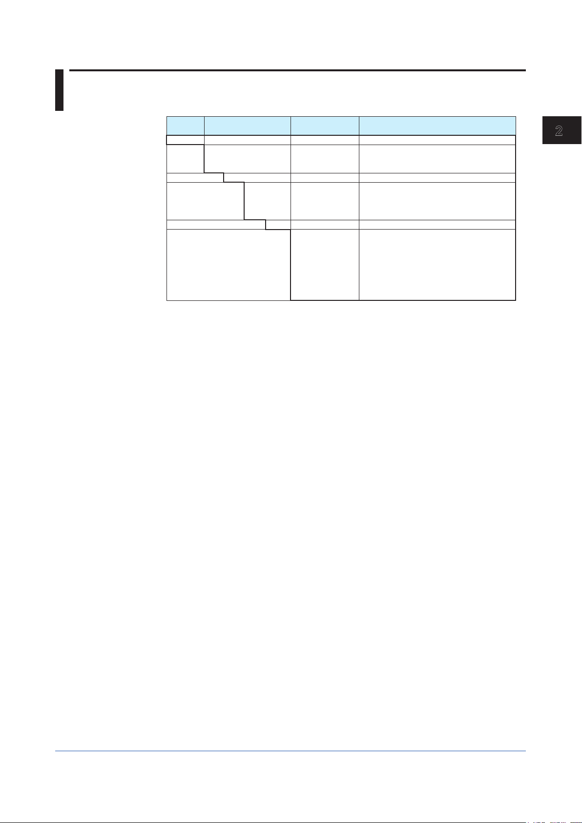
Manual Title Manual No. Description
Rack-Mounted Instruments IM 1B4F2-01E Describes mounting and wiring for the YS80 rack-mounted instruments.
Model JHT200 Handy Terminal IM 77J50H01-01EN Describes operation of JHT200.
1
1
Introduction
IM 01B04K01-02E
1-1
Page 6
1.1 Inspection
The SKYD alarm unit is shipped only after stringent inspection at the factory. Visually inspect
the product upon delivery to make sure it is not damaged in any way.
Store the box and inner packing material of the package in a safe place / they may be
needed if there is a problem with the product and it needs to be sent back for repair.
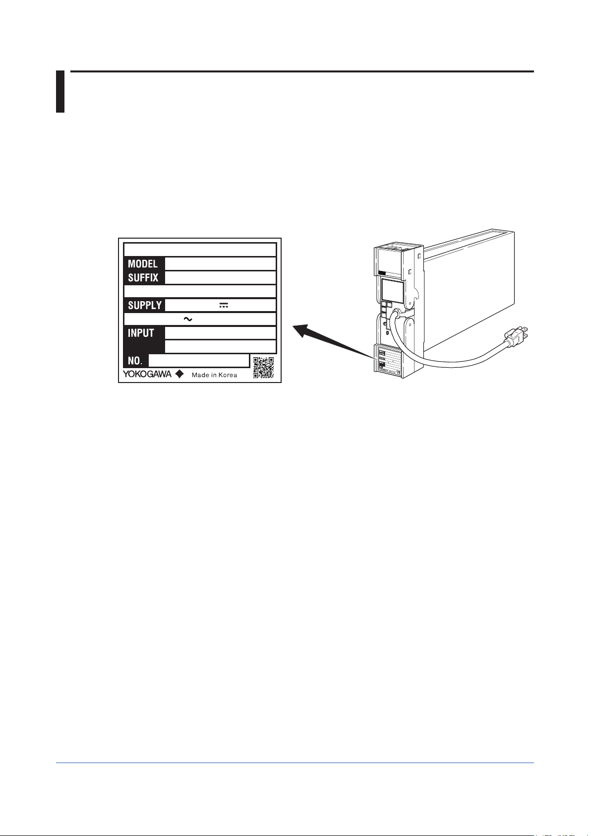
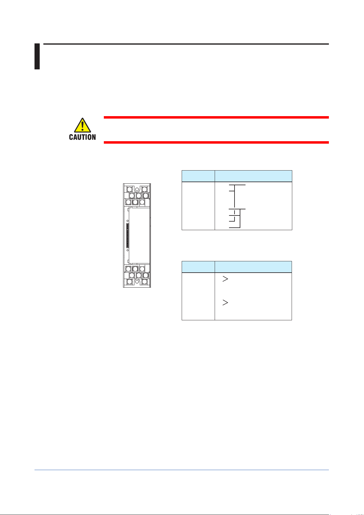
Check of Model and Suffix Codes
The model and suffix codes are indicated on the Name plate attached to the front cover of
the instrument. Crosscheck this information with the model and suffix codes of Section 2.2
to ensure that the product is as specified in the order.
ALARM UNIT
SKYD
-204*S
24-110VDC
100-120VAC 50/60Hz
60mA
6.0VA
1-5VDC
ALARM UNIT
SKYD
-204*S
24-110VDC
100-120VAC 50/60Hz
60mA
1-5VDC
XXXXXXXXX
Figure 1-1 Name plate for Thermocouple Input (Description example)
6.0VA
XXXXXXXXX
Confirmation of the Package Contents
Check the package contents against the list below. If anything is missing or damaged,
immediately contact the sales office from which you purchased the product or your nearest
Yokogawa representative.
• SKYD Alarm Unit ..............................................................................................1
• Alarm Label (Parts No.: L4040JA) .....................................................................1
• Precautions on the Use of the YS80 Series ......................................................1
Downloadable Electronic Manuals
You can download the latest manuals from the following website:
http://www.yokogawa.com/ns/ys/
F0101.ai
1-2
IM 01B04K01-02E
Page 7
1.2 Documentation Conventions
This manual uses the following notational conventions
Symbols
The following symbols are used in this manual.
Markings
Indicates that operating the hardware or software in a particular
manner may damage it or result in a system failure.
Draws attention to information that is essential for understanding the
operation and/or features of the product.
1
1
Introduction
Description of Displays
Some of the representations of product displays shown in this manual may be exaggerated,
simplified, or partially omitted for reasons of convenience when explaining them.
QR Code
The product has a QR Code pasted for efficient plant maintenance work and asset
information management. It enables confirming the specifications of purchased products and
user’s manuals.
For more details, please refer to the following URL.
https://www.yokogawa.com/qr-code
QR Code is a registered trademark of DENSO WAVE INCORPORATED.
Note
Gives additional information to complement the present topic and/or
describe terms specific to this document.
Gives reference locations for further information on the topic.
IM 01B04K01-02E
1-3
Page 8
1.3 Notice
This Instruction Manual
• This manual should be passed on to the end user. Keep at least one extra copy of the
manual in a safe place.
• Read this manual carefully to gain a thorough understanding of how to operate this
product before you start using it.
• This manual is intended to describe the functions of this product. Yokogawa Electric
Corporation (hereinafter simply referred to as Yokogawa) does not guarantee that these
functions are suited to the particular purpose of the user.
• Under absolutely no circumstances may the contents of this manual, in part or in whole,
be transcribed or copied without permission.
• The contents of this manual are subject to change without prior notice.
• Every effort has been made to ensure accuracy in the preparation of this manual. Should
any errors or omissions come to your attention however, please contact your nearest
Yokogawa representative or sales office.
Protection, Safety, and Prohibition against Unauthorized Modification
• The following safety symbols are used on the product and in this manual.
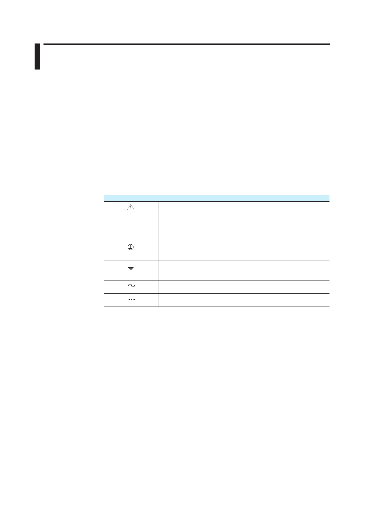
Markings
CAUTION
• In order to protect the product and the system controlled by it against damage and ensure
its safe use, make certain that all of the instructions and precautions relating to safety
contained in this document are strictly adhered to. Yokogawa does not guarantee safety
if products are not handled according to these instructions.
• If protection/safety circuits are to be used for the product or the system controlled by it,
they should be externally installed on the product.
• Do not turn off the power of the product during adjustment and parameter setting.
• Be sure to confirm the parameters referring to ‘‘5.4 Parameter List’’ before installing the
product in a system or plant. After confirming them, install the product in a system or plant
and turn on the power.
• When you replace the parts or consumables of the product, only use those specified by
Yokogawa.
• If the product is to be used in systems with special requirements for human safety, such
in as nuclear power and radiation related equipment, railway facilities, aircraft facilities,
and medical devices, please consult with your sales representative.
• Do not modify the product.
Force Majeure
• Yokogawa does not make any warranties regarding the product except those mentioned
in the WARRANTY that is provided separately.
• Yokogawa assumes no liability to any party for any loss or damage, direct or indirect,
caused by the use or any unpredictable defect of the product.
If this symbol is indicated on the product, the operator should refer
to the explanation given in the instruction manual in order to avoid
personal injury or death to either themselves or other personnel, and/
or damage to the instrument. The manual describes that the operator
should exercise special care to avoid shock or other dangers that may
result in injury or loss of life.
Protective ground terminal:
This symbol indicates that the terminal must be connected to ground
prior to operating the equipment.
Function ground terminal:
This symbol indicates that the terminal must be connected to ground
prior to operating the equipment.
AC voltage:
This symbol indicates that AC voltage is present.
DC voltage:
This symbol indicates that DC voltage is present.
1-4
IM 01B04K01-02E
Page 9

1.4 Compatibility with Previous Models
Compatibility with style A
● Operation and settings differ from previous model (styles A). Please read this document
carefully before operating the product.
● Before installing this product in a system or plant, you must check the jumper settings and
parameters described in chapter 5, “Settings.” After checking settings and parameters,
install the product in the system or plant, and then turn ON the power.
Compatibility with style R
● Operation and settings are the same as for the previous model (style R). Please read this
document carefully before operating the product.
● Before installing this product in a system or plant, you must check the jumper settings and
parameters described in chapter 5, “Settings.” After checking settings and parameters,
install the product in the system or plant, and then turn ON the power.
1
1
Introduction
IM 01B04K01-02E
1-5
Page 10

Blank
Page 11
121
Chapter 2 General
General
The Model SKYD Alarm Unit provides two types of alarms : absolute alarm that is output
after comparison of one input signal with one or two alarm set points, and deviation alarm
that is output after comparison of the deviation between two inputs with two alarm set points.
Direct or reverse alarm action can be selected for each of the alarm output set points. The
front panel is provided with an alarm LED indicator lamp for confirming alarm relay action
(when relay is energized).
The JHT200 Handy Terminal (*1) is used for setting the SKYD parameters.
On the SKYD model with display setter (SKYD-x04), input indication (engineering unit) can
be displayed and alarm set points can be displayed / set on the front panel.
*1: The modular jack conversion adapter (E9786WH) is required for connecting the JHT200 Handy
Terminal to the Alarm Unit.
The 5 pin-connector type communication cable (F9182EE) and modular jack conversion adapter
(E9786WH) is required for connecting the BT200 BRAIN Terminal of YOKOGAWA ELECTRIC
Corporation
2
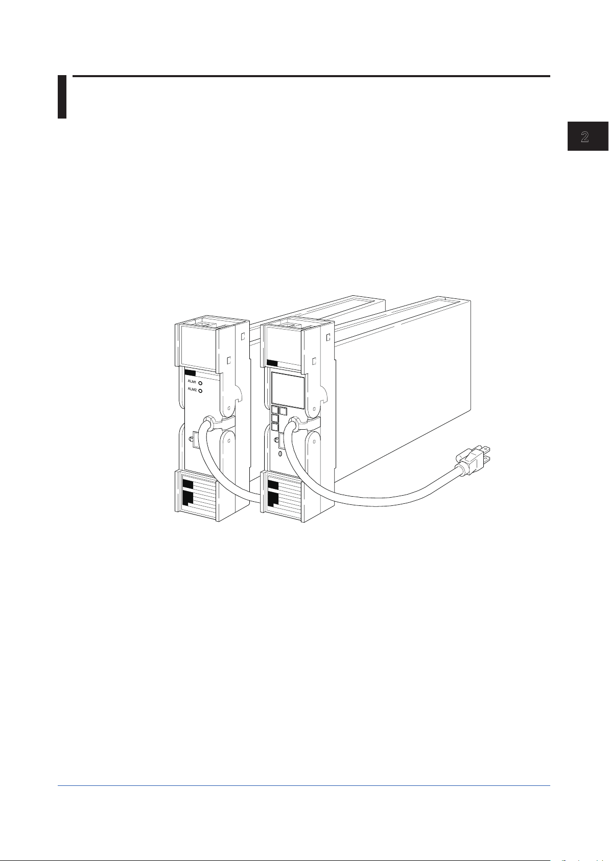
General
Figure 2-1 External View
IM 01B04K01-02E
F0201.ai
2-1
Page 12

2.1 Standard Specifications
Please see the General Specifications (GS 01B04K01-02E) at the end of this manual.
2-2
IM 01B04K01-02E
Page 13
121
2.2 Model and Suffix Codes
Model Suffix Codes Optional
SKYD Alarm Unit
Alarm -1
Sux Code 0 Always 0
Setting Scale
Style Code *S Style S
Option Codes
-2
-3
(*1)
(*4) (*5)
*1: In the case of two set points, the setting ranges of one set point/two set points are the same.
*2: The value obtained by squaring the setting value functions as the alarm setting value.
*3: 2-input deviation alarm only
*4: /LOCK, /REK, /TB, /A2TB, and /A2ER cannot be specified together.
*5: /FBP, /A2TB, and /A2ER cannot be specified together.
0
1
2
4
Suffix Codes
/NHR
/FBP
/LOCK
/WSW
/REK
/TB
/A2TB
/A2ER
1 input, 1 setpoint absolute alarm
1 input, 2 setpoints absolute alarms
2 inputs, 2 setpoints deviation alarms
0 to 100 linear
0 to 10 square root
-100 to +100 linear (deviation alarm)
Actual scale (with display setter)
Without rack case
Power supply fuse bypass
Power supply plug with lock
With spring washer
Mount to same line with EK series rack
With power supply terminal
220V version with power supply terminal
220V version with power supply plug
Description
(*2)
2
General
(*3)
IM 01B04K01-02E
2-3
Page 14

2.3 Accessories
Alarm Label: 1 sheet
2-4
IM 01B04K01-02E
Page 15

1
2
1
2
Chapter 3 Installation
Installation
For details of the installation procedure and wiring precautions, refer to the instruction
manual “Installation of Rack-Mounted Instruments” (IM 1B4F2-01E).
3
3
Installation
IM 01B04K01-02E
3-1
Page 16
3.1 External Wiring
(a) All cable ends must be furnished with crimp-on type solderless lugs (for 4mm screws)..
(b) Draw out the internal unit from the rack case.
(c) Connect the cables to the correct terminals referring to Figure 3-1.
(d) Return the internal unit into the rack case after completing the wiring.
(e) Always return the terminal block cover to its original position after completing the wiring.
The terminal block cover cannot be returned to its original position if the internal
unit is not installed its original position in the rack case. Securely return the terminal
block cover because it also functions as lock for the internal unit.
Terminal arrangement
OUT
K
J
HFDCB
A
Terminal
Designation
A NC
Description
Alarm output 1
B COM
C
D
F NC Alarm output 2
(*1)
H COM
J NO
K NO
Do not connect to the output terminal when the terminal is not
in use.
*1: Except SKYD-1 type.
Terminal
Designation
1 +
2 3
4
3
5
1
2
4
6
8
7
IN
5 +
6 7
8
*2: For SKYD-3 type only.
Figure 3-1 Terminal Layout and Terminal Wiring
Input 1
Input 2
Description
(*2)
3-2
IM 01B04K01-02E
Page 17
1
2
1
2
3.2 Example of Alarm Wiring
The SKYD alarm unit provides various types or alarms depending on the setting of the alarm
action or the method of connecting the alarm output terminals. Thus, the necessary wiring
should be made with reference to the following two examples:
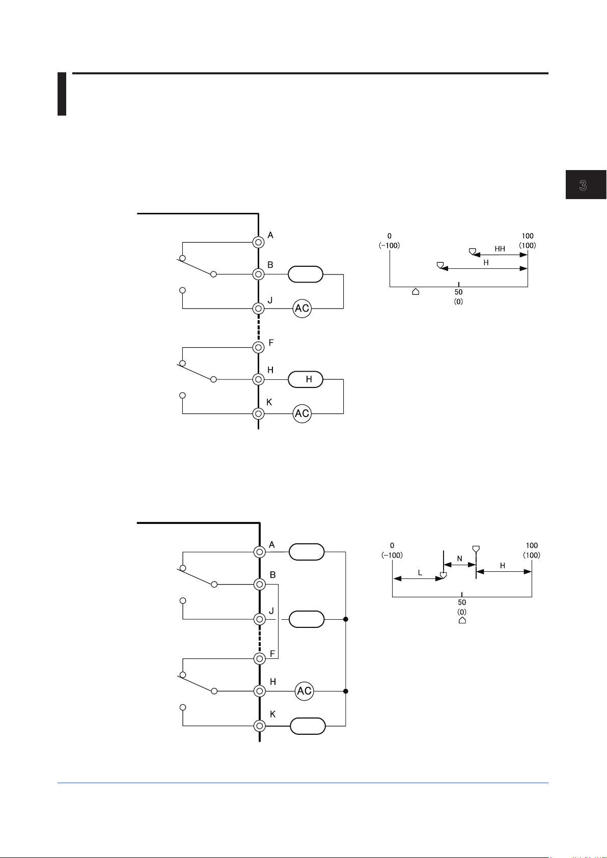
3.2.1 High-limit and High-high-limit Alarms
Set the direct action (DIRECT) for the alarm actions of both alarms 1 and 2. Then wire the
terminals as illustrated in Figure 3-2.
SKYD Alarm Unit
H
H
Alarm 1 setting
Input (deviation)
value
Alarm 2 setting
3
3
Installation
Alarm output terminal
Figure 3-2 External Wiring - Example 1
F0302.ai
3.2.2 Three-position Alarm
Set the reverse action (REVERSE) for the alarm action of alarm 1, and the direct action
(DIRECT) for the alarm action of alarm 2. Then wire the terminals as illustrated in Figure 3-3.
SKYD Alarm Unit
N
L
H
Alarm output terminal
Figure 3-3 External Wiring - Example 2
Alarm
Alarm 2 setting
Alarm 1 setting
Input (deviation) value
F0302.ai
IM 01B04K01-02E
3-3
Page 18

3.2 Example of Alarm Wiring
Applicable Cables
(1) Signal circuit wiring
(2) Alarm circuit wiring
(3) Power supply wiring
• Cross-sectional area of the cable conductor: 0.5 to 0.75 mm
2
• Examples of applicable cables: Single core PVC insulated flexible cable (VSF)
stranded wires (JIS C 3306); heat-resistant vinyl-insulated cable (UL style 1007)
• Cross-sectional area of the cable conductor: 0.5 to 1.25 mm
2
• Examples of applicable cables: 600 V PVC insulated cable (IV) stranded wires (JIS C
3307); PVC insulated cable for electric appliances (KIV) stranded wires (JIS C 3316);
heat-resistant vinyl-insulated cable (UL style 1007)
• Cross-sectional area of the cable conductor: 1.25 to 2.00 mm
2
• Examples of applicable cables: 600 V PVC insulated cable (IV) stranded wires (JIS C
3307)
3-4
IM 01B04K01-02E
Page 19
1
2
3
1
2
3
Chapter 4 Principles of Operation
4.1 Principle of Operation
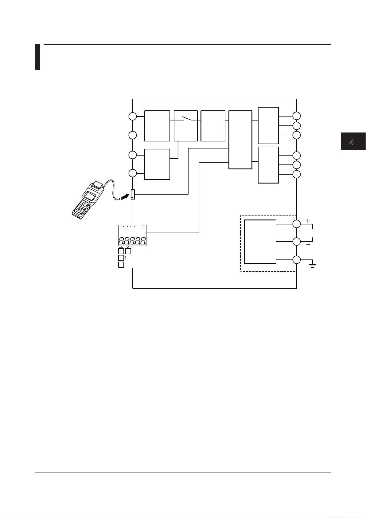
Input signals are converted to digital data by the A/D conversion circuit. The resulting digital
data is processed (square root calculation, etc.) by the microcomputer, and the alarm relay
is then energized/de-energized by alarm calculation processing (comparison, etc.).
1
2
5
6
Handy
Terminal
SET
Figure 4-1 Hardware Function Block Diagram
Input
processing
circuit 1
Input
processing
circuit 2
(*1)
Display setter (*2)
*1: SKYD-30x only
*2: SKYD-x04 only
*3: Except SKYD-10x
Multiplexer
conversion
A/D
circuit
Micro-
processor
Relay
output 1
Relay
output 2
(*3)
Power
supply circuit
A
B
J
F
H
K
L
Power
supply
N
GND
F0401.ai
App
4
Principles of Operation
IM 01B04K01-02E
4-1
Page 20
4.2 Description of Functions
The following describes the functions of the SKYD-10x/20x and SKYD-30x.
4.2.1 SKYD-10x/20x Functions
Input signal
A/D conversion
1 to 5 VDC
Normalization
INPUT1
Square root calculation
LINEARIZE1
LOW CUT1
Scaling (*1)
Bias (*1)
PV1
Alarm detection 1
Alarm relay connection 1
BIAS1
SET POINT1
HYSTERESIS1
ALM1 ACTION
ON DELAY1
OFF DELAY1
RLY1 ACTION
Relay output 1 Relay output 2
Figure 4-2 Software Function Block Diagram
The alphabet codes in the figure are the names of BRAIN communication parameters.
*1: SKYD- 04 only
RLY1 TEST
SCH1
SCL1
DP1
SKYD-20 only
Alarm detection 2
Alarm relay connection 2
SET POINT2
HYSTERESIS2
ALM2 ACTION
ON DELAY2
OFF DELAY2
RLY2 ACTION
RLY2 TEST
F0402.ai
4-2
IM 01B04K01-02E
Page 21

1
2
3
1
2
3
4.2 Description of Functions
●ExplanationofInputprocessingblock
• A/D conversion:
Performs A/D conversion on input signals.
• Normalization:
A/D-converted signals are converted to a scale of 1 to 5 V DC. (INPUT1)
• Square root calculation (LINEARIZE1):
When square root calculation is set to ON, the input processing block performs square
root calculation on the input signal.
The low-cut point (LOW CUT1) can be set to the square root calculation. The figure
below shows operation when the input signal is near the low-cut point. This low-cut
point is provided with a hysteresis of 0.2%.
Input after low-cut processing
App
4
Principles of Operation
When X
X - 1 + 1
≤1V: Y=X
Input (X)
F0403.ai
Y = 2 x
X =
Y Y,X: 1 to 5 (V)
Low-cut point
Hysteresis fixed at 8 mV (0.2%)
• Scaling (SKYD-x04 only):
The display in engineering unit is available according to the SCH1, SCL1 and DP1
parameter settings.
The value after scaling (or, when the bias function is used, the value obtained by
adding bias to this value) becomes PV1.
SCH1, SCL1, DP1 setting (default: 0.0 to 100.0)
<Setting Method>
(1) Set the decimal point position matched to the unit system actually in use at DP1.
(Example: two digits past the decimal point)
(2) Register the measuring input scale range at SCH1 and SCL1.
(Example: SCH1=20.00, SCL1=0.00)
(Example)
1V 5V
0.0 (SCL1) 100.0 (SCH1)
0.00 (SCL1) 20.00 (SCH1)
IM 01B04K01-02E
Decimal point position registered at DP1.
Default scale
Measuring input scale
(after scaling)
F0404.ai
4-3
Page 22

4.2 Description of Functions
Reverse scaling (SCH1 < SCL1) is also possible.
A setting error occurs when SCH1 is set to equal SCL1.
● ExplanationofAlarmdetectionblock
• Bias:
A bias value (BIAS1) can be added to scaling values.
This allows error to be compensated when there is an error between the input value
and the indicated value.
Bias can be set within the range ±10% [(SCH1 - SCL1) x 0.1] of the scaling width.
The input value displayed on the display setter on the front panel (PV1 in the BRAIN
communications parameter) is the value after addition of bias.
In the following description, n is "1" for SKYD-10x, and "1" or "2" for SKYD-20x.
• Alarm detection n:
Performs alarm detection.
• ALMn ACTION: Alarm action
Direct .................. The alarm state is entered when the input value is at the preset
alarm set point or higher.
Reverse...............The alarm state is entered when the input value is at the preset
alarm set point or lower.
• SET POINTn: Alarm set point
• HYSTERESISn: Alarm hysteresis (See Figure 4-4.)
• ON DELAYn: Alarm ON delay
Sets the dead time until the alarm turns ON.
An alarm state is entered when the input value is in the alarm range for the duration
set at ON DELAYn.
If input returns to the normal range before the time set at ON DELAYn is reached, the
alarm does not turn ON.
• OFF DELAYn: Alarm OFF delay
Sets the dead time until the alarm turns OFF.
A normal state is entered when the input value is in the normal range for the duration
set at OFF DELAYn.
If input returns to the alarm range before the time set at OFF DELAYn is reached, the
alarm does not turn OFF.
4-4
• For ON DELAY/OFF DELAY, if you change the time during a delay, cancel the delay
operation, and restart operation with the set delay time.
• The alarm function does not work for 3 seconds after power ON.
● Relayoutputblock
• RLYn ACTION: Alarm relay action
Energized at normal operation ............ The relay is energized when the alarm
detection result is a normal state.
De-energized at normal operation....... The relay is energized when the alarm detection
result is an alarm state.
• RLYn TEST: Relay action test
This function is for testing relay action.
Relays can be turned ON/OFF without influencing the currently alarm detection result.
Direction of alarm relay action: De-energized at normal operation (Factory-shipped settings)
ALMn Direction of alarm action Input value < Set point Set point < Input value
DIR Direct (high-limit alarm) Output relay de-energized Output relay energized
RVS Reverse (low-limit alarm) Output relay energized Output relay de-energized
Direction of alarm relay action: Energized at normal operation
ALMn Direction of alarm action Input value < Set point Set point < Input value
DIR Direct (high-limit alarm) Output relay energized Output relay de-energized
RVS Reverse (low-limit alarm) Output relay de-energized Output relay energized
IM 01B04K01-02E
Page 23

1
2
3
1
2
3
4.2.2 SKYD-30x Functions
4.2 Description of Functions
Input signal 1
A/D conversion
1 to 5 VDC
Normalization
INPUT1
Square root calculation (*1)
Scaling (*1)
Bias (*1)
PV1
Deviation (subtraction)
INPUT DEV
Alarm detection 1
Alarm relay connection 1
*1: SKYD-304 only
LINEARIZE1
LOW CUT1
SCH1
SCL1
DP1
BIAS1
SET POINT1
HYSTERESIS1
ALM1 ACTION
ON DELAY1
OFF DELAY1
RLY1 ACTION
RLY1 TEST
Relay output 1 Relay output 2
Figure 4-3 Software Function Block Diagram
Input signal 2
A/D conversion
Normalization
INPUT2
Square root calculation (*1)
Scaling (*1)
Bias (*1)
PV2
Alarm detection 2
Alarm relay connection 2
1 to 5 VDC
BIAS2
*1: SKYD-304 only
HYSTERESIS2
ALM2 ACTION
OFF DELAY2
SET POINT2
ON DELAY2
RLY2 ACTION
RLY2 TEST
F0405.ai
App
4
Principles of Operation
The alphabet symbols in the figure are the names of BRAIN communication parameters.
In the following descriptions, n is "1" or "2".
● Input processing block
Functions are the same as SKYD-10x/20x except that there are two inputs.
• Input deviation processing block
Input deviation INPUT DEV is the value of "PV1 - PV2".
● Alarm detection block
Functions are the same as SKYD-20x except that the detection target is input deviation
INPUT DEV.
● Relay output block
Functions are the same as SKYD-20x.
IM 01B04K01-02E
4-5
Page 24

4.3 Example of Alarm Function Setting
This section describes the alarm function setting showing the example using the alarm
function parameters.
4.3.1 Condition of Alarm Function
Set the following conditions.
(1) Condition for Alarm 1
The alarm is output when the status where the input value is 80% or more continues for 1
second or more.
The alarm is released when the status where the input value is 70% or less continues for
2 seconds or more.
(2) Condition for Alarm 2
The alarm is output when the input value is 15% or less.
The alarm is released when the input value is 20% or more.
4.3.2 Parameters of Alarm Function
The table below shows the parameters the condition of alarm function described in 4.3.1 is
placed to.
Table 4-1 Table of Parameter Setting Example for Alarm 1 and Alarm 2 (SKYD-20x)
Item Alarm 1 Alarm 2
Alarm set point E01: SET POINT1 80% E02: SET POINT2 15%
Direction of alarm action E07: ALM1 ACTION DIRECT E08: ALM2 ACTION REVERSE
Alarm hysteresis E09: HYSTERESIS1 10% E10: HYSTERESIS2 5%
Alarm ON delay E15: ON DELAY1 1 s E16: ON DELAY2 0 s
Alarm OFF delay E17: OFF DELAY1 2 s E18: OFF DELAY2 0 s
Parameter Set point Parameter Set point
4.3.3 Operating Condition of Alarm Function
Refer to the following figure for operating condition of alarm 1 and alarm 2.
Alarm condition established
100
Alarm-1 set point >
Alarm-2 set point >
Alarm-1 Direct
action
Alarm-2 Reverse
action
80
60
40
20
Alarm-2 hysteresis (5%)
15
0
De-energized
Figure 4-4 Alarm Action
Alarm-released condition established
1 s 2 s
Energized
De-energized
Alarm-1 hysteresis (10%)
Alarm condition established
Alarm-released condition established
Elapsed time (s)
De-energized
Energized De-energized
F0406.ai
4-6
IM 01B04K01-02E
Page 25

1
2
3
App
1
2
3
4
Chapter 5 Setting
Setting
Items to Confirm before Start of Operation
Before you start operation, inspect and confirm the following items:
(1) Draw out the internal unit from the rack case, and make sure that the specified fuses are
properly mounted in the fuse holders at the rear of the internal unit.
(2) When inserting the internal unit into the rack case, firmly connect the multi-pin connectors
for connecting the internal unit and the case.
(3) Make sure that power plugs are properly connected to the power outlet.
(4) Make sure that external wiring to the terminal block is properly connected.
Refer to Section 7.1, “Action in Fault Condition” for how to detect device error by
alarm output.
5
Setting
IM 01B04K01-02E
5-1
Page 26

5.1 Names of Components
The following shows the names of SKYD components.
ALM SP
1
2
Alarm 1,2 relay action indicator lamps (ALM1,2)
Alarm 1,2 set point indicator lamps (SP1,2)
1 2
Display setter
Data digit feed key
Parameter selection key
Tag plate
Alarm 1,2 relay action indicator lamps (ALM1,2)
BRAIN connector (w/ cover)
Key setting enable switch
(ENBL switch)
Name plate
Other than SKYD-x04
SKYD-x04
Output terminal block
SET
Main board
Data change key
SET
Data setting fix key
Terminal block cover/handle
for drawing out internal unit
Rack case
Input terminal block
Multi-pin connector
Power plug
Figure 5-1 Names of Components
5-2
F0501.ai
IM 01B04K01-02E
Page 27

1
2
3
App
1
2
3
4
5.2 Setting Jumper
The SKYD is provided with the following jumpers.
Other SKYDs excluding the SKYD-x04 are not provided with the ALM1, 2 jumpers.
(Can be set by using the JHT200 Handy Terminal.)
Jumper Code Jumper Name Except SKYD-x04 SKYD-x04
W. P. Parameter Write Protect Available Available
ALM1 Alarm 1 action setting jumper Not available Available
ALM2 Alarm 2 action setting jumper
(except SKYD-10x)
• Parameter Write Protect jumper
When this jumper is set to ON, changing of parameters by the key switches and Handy
Terminal is disabled. “LOC” will be displayed on the display setter if the “→” switch is
pressed with the SP1 or SP2 parameter displayed on the display setter.
To cancel the “LOC” display and return to the previous display, press any key.
• Alarm action setting jumper
This jumper is for setting the direction of alarm action.
The table below shows the relationship between direction of alarm action and direction of
relay action.
Direction of alarm relay action: De-energized at normal operation
ALMn Direction of alarm action Input value < Set point Set point < Input value
DIR Direct (high-limit alarm) Output relay de-energized Output relay energized
RVS Reverse (low-limit alarm) Output relay energized Output relay de-energized
Not available Available
5
Setting
Direction of alarm relay action: Energized at normal operation
ALMn Direction of alarm action Input value < Set point Set point < Input value
DIR Direct (high-limit alarm) Output relay energized Output relay de-energized
RVS Reverse (low-limit alarm) Output relay de-energized Output relay energized
IM 01B04K01-02E
5-3
Page 28

5.2 Setting Jumper
5.2.1 Check of Setting Jumper and its Location
The setting jumpers are located on the main board of the internal unit.
Draw out the internal unit, and check the current jumper settings.
Current jumper settings can also be checked on the JHT200 Handy Terminal.
Parameter Write Protect A55: WRT PROTECT
Direction of alarm 1 action E07: ALM1 ACTION
Direction of alarm 2 action (except SKYD-10x) E08: ALM2 ACTION
Parameter Write
Protect
ON disables
changing of
parameters.
Jumper Name Parameter Name
Direction of alarm
action
Direct
action
selected
Reverse
action
selected
Setting jumpers
(factory-set default)
F0502.ai
Figure 5-2 Setting Jumper
Change of Setting Jumper
Follow the procedure below to change the setting jumpers:
(a) Pull the terminal block cover toward you to draw out the internal unit from the rack case.
(b) Check the jumpers on the main board of the internal unit, and change their settings as
desired. Use tweezers or another fine-tipped object to change the setting jumpers.
(c) Return the internal unit to the rack case.
(d) Return the terminal block cover to its original position.
5-4
F0502.ai
IM 01B04K01-02E
Page 29

1
2
3
App
1
2
3
4
5.3 Setting of Parameters
This instrument has BRAIN communication parameters for specifying functions and
adjusting input. Connect JHT200 Handy Terminal (*1) to the instrument to display or set
parameters (modular jack conversion adapter (E9786WH) is required )
On the SKYD model with display setter (SKYD-x04), input indication (engineering unit) can
be displayed and alarm set points can be display/set on the front panel.
For details on parameters, refer to the Parameter Lists.
*1: BT200 BRAIN Terminal of YOKOGAWA ELECTRIC Corporation can also be used.
When connecting the JHT200 Handy Terminal, the adapter for modular-jack (model E9786WH)
is required. When using the BT200 BRAIN Terminal of YOKOGAWA Electric Corporation, the
communication cable of 5-pin connector type (model F9182EE) and the adapter for modularjack
(model E9786WH) are required.
5.3.1 Parameter Change Disable Function
The SKYD is provided with a parameter change disable function for preventing parameter
settings from being changed by operator error.
Table 5-1 Parameter Change Disable Function
Disable Setting Method Disable Cancel
Parameter Write
Protect jumper
Enable switch
(SKYD-x04 only)
Set W.P. jumper on the main
board to “ON”.
Changes cannot be made if no
settings are made for 30 minutes
after operating any key switch
on the front panel in a setting
change enable state.
Method
Set W.P. jumper on
the main board to
“OFF”.
Press the Enable
switch.
5
Setting
Description of Disable
Operation
● Changing of parameter
setting by key switches.
● Changing of parameter
setting by Handy Terminal.
● Changing of parameter
setting by key switches.
5.3.2 Setting of Parameters Using Display Setter (SKYD-x04)
On the SKYD-x04, you can change alarm set point using the display setter on the front
panel.
Other parameters are changed using the JHT200 Handy Terminal.
The table below describes the relationship between key switch operations and migration of
display states.
Table 5-2 Relationship between Key Switch Operations and Migration of Display States
Key
Switch
∆ Displays the next
→ Advances to the setting
↑ Displays the previous
SET No operation Advances to the setting fix
ENBL Enters setting change enable state.
Display Mode Setting Change Mode Setting Fix Mode Indicator Out Mode
parameter.
change mode when a
settable or changeable
parameter is displayed in
the setting change enabled
state. (*1)
parameter.
Enable switch is disabled if the Parameter Write Protect jumper is set to “ON”.
*1: When the Parameter Write Protect jumper on the main board is set to “ON”, the SKYD will not
advance to the setting change mode. In this state, “LOC” is displayed on the display setter.
Cancels the newly changed
values, returns to the
display mode, and displays
the next parameter.
Moves setting digit. Returns to the setting
Changes the set point. No operation
mode.
Display Function
Cancels the newly changed
values, returns to the
display mode, and displays
the next parameter.
change mode, and moves
to the next digit.
Fixes the set point, and
advances to the display
mode.
This mode is entered if no
key switches are operated
for 30 minutes when the
display mode parameter is
set to “OFF”.
The display mode is
returned to if any key switch
is pressed in the indicator
out mode.
IM 01B04K01-02E
5-5
Page 30

5.3 Setting of Parameters
Indicator out mode is
entered if no key switch is
operated for 30 minutes
when display mode
parameter is "OFF".
Indicator out mode Display mode
Display mode is returned to
when any key switch is
pressed.
Moves to setting
Cancels new set point
value, returns to display
mode, and displays next
parameter.
Setting fix mode Setting change mode
(all digits flashing)
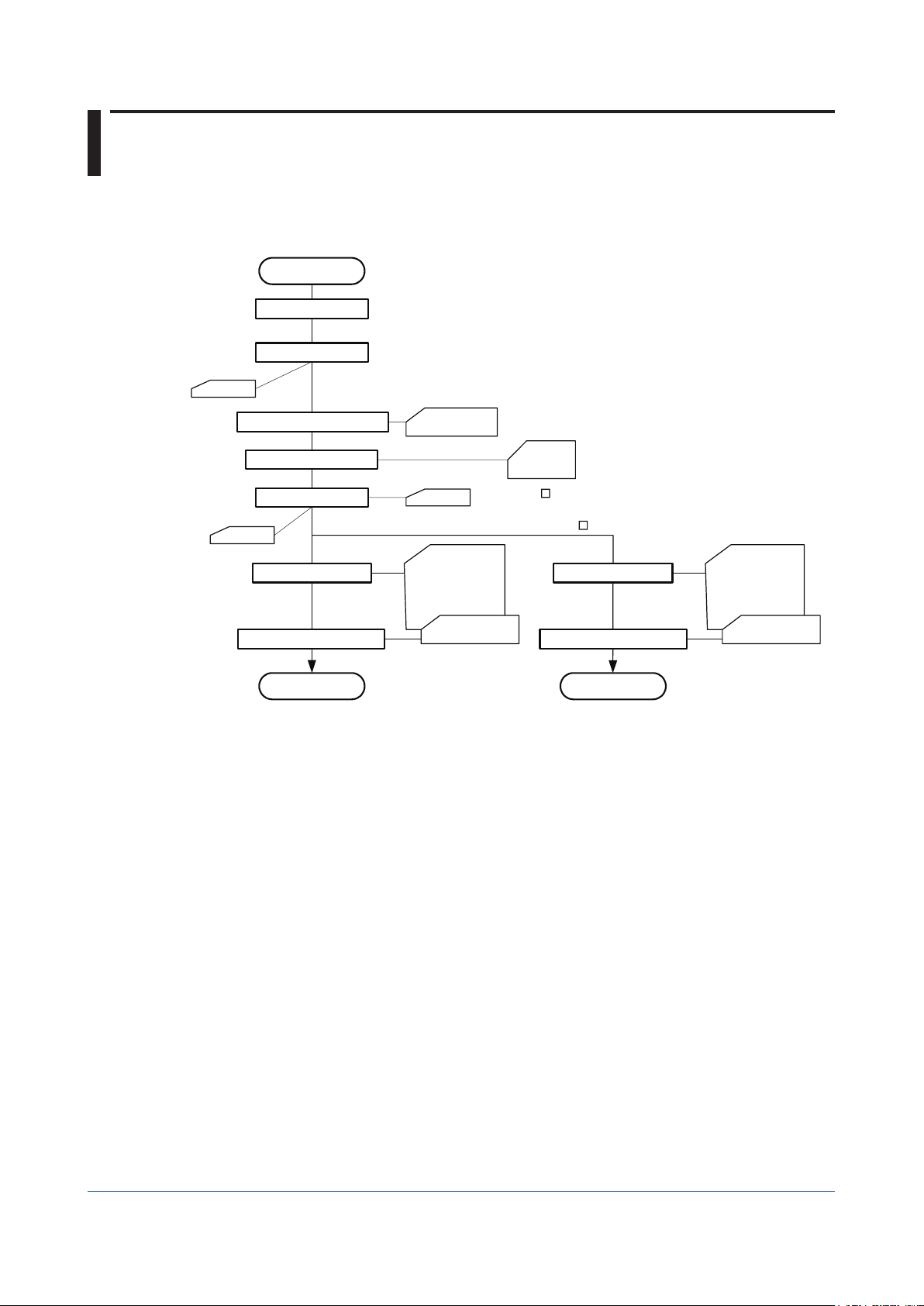
Figure 5-3 Key Switch Operations and Migration of Display States
Fixes set point, and moves
to display mode.
Moves to setting fix
mode.
Returns to setting change
mode, and moves to next digit.
change mode.
Displays previous parameter.
Displays next parameter.
Feeds digit.
Increments value.
Switching the Display
Each press of the ∆ key switches the display data.
Cancels new set point,
returns to display mode,
and displays next
parameter.
F0503.ai
Power on
Press key.
Input value (PV1) is
displayed.
SP1 /SP2 lamps out
In this example,
"40.00"
Figure 5-4 Progression of Display Screen
Alarm 1 set point (SP1)
is displayed.
SP1 lamp lit
In this example,
"50.00"
LED Indicator Lamps
The table below lists the type of LED indicator lamps on the front panel and their lighting
conditions.
LED Lamp Color Lighting Conditions Remarks
ALM1 Yellow Lit when alarm 1 output relay is energized
ALM2 Yellow Lit when alarm 2 output relay is energized SKYD-20x, -30x only
SP1 Green Lit when alarm 1 set point (SP1) is displayed on the
SP2 Green Lit when alarm 2 set point (SP2) is displayed on the
display setter
display setter
Press key.
Press key.
Alarm 2 set point (SP2)
is displayed.
SP2 lamp lit
In this example,
"30.00"
SKYD-x04 only
SKYD-204, -304 only
F0504.ai
5-6
IM 01B04K01-02E
Page 31

1
2
3
App
1
2
3
4
Setting Parameters
Display the desired parameter (e.g. alarm set point), and follow the procedure below to
change its set point.
AL M S P
1
2
1 2
SET
AL M S P
1
2
1 2
SET
5.3 Setting of Parameters
(1) Input value (60.00) is displayed at power ON.
Press the - key. The SP1 lamp lights, and the alarm 1 set point is displayed.
(2) The alarm 1 set point (80.00) is displayed.
Press the - key. In the case of the SKYD-104, the SP1 lamp goes out, and the
input value is displayed.
In the case of the SKYD-204/304, the SP2 lamp lights, and
the alarm 2 set point is displayed.
AL M SP
1
2 1 2
Alarm 2 set point (30.00) is
displayed. (SKYD-204/304 only)
5
Setting
(3) Press the ENBL switch to enter setting change enable state.
(4) Set the alarm set point. (Change the alarm 1 set point to "70.00" from "80.00".)
Alarm set points whose SP lamp is lit can be changed.
Press the - key.
Press the - key.
Press the - key.
Figure 5-5 Setting Parameters
SET
The uppermost digit on the display flashes.
Hold down the key to move the flashing section to the digit
on the right.
This increments the value at the flashing digit. Hold down the
key to feed the value to "7".
All parameter digits flash. Pressing the key again
causes "70.00" to light. (This fixes the new parameter
settings.).
SET
F0505.ai
● WhentheParameterWriteProtectjumperonthemainboardissetto“ON”,the
SKYD will not advance to the setting change mode. In this state, “LOC” is dis-
played on the display setter.
● Donotturnoffthepoweroftheinstrumentduringparametersetting.
IM 01B04K01-02E
5-7
Page 32

5.3 Setting of Parameters
Display at Power ON
The model with display setter displays REV NO. (revision number of software for the SKYD)
for about 2 seconds after power ON.
Example of display (REV NO.10)
LOC Display
When “LOC” is displayed, this indicates that parameter settings cannot be changed.
(The Parameter Write Protect jumper on the main board is set to “ON”.)
To cancel the “LOC” display and return to the previous display, press any key.
Indicator Out Mode Display
In this mode, only the decimal point is displayed on the display setter.
When the display mode parameter (DSP MODE) is set to “OFF”, and no key operation is
performed for 30 minutes, the SKYD moves to the indicator out mode.
To cancel this mode and return to the display mode, press any key switch.
I/O signal processing and calculations are performed as usual even in the indicator out
mode.
If the self check discovers an error (A/D conversion error, EEPROM error, EEPROMSUM
error) in the indicator out mode, this mode is canceled, and the error is displayed. Also,
the SKYD does not move to the indicator out mode when an error (A/D conversion error,
EEPROM error, EEPROMSUM error) occurs.
1 2 1 2
Moves to indicator
out mode if no key is
operated for 30
minutes.
Indicator out mode
Only decimal point is lit.
Figure 5-6 Indicator Out Mode
Press any key.
1 2 1 2
Normal operation
mode
F0506.ai
5-8
IM 01B04K01-02E
Page 33

1
2
3
App
1
2
3
4
5.3.3 Setting of Parameters Using Handy Terminal
For details of operation and adjusting procedures of JHT200 Handy Terminal, refer to
the instruction manual “JHT200 Handy Terminal” (IM 77J50H01-01EN).
<Connection>
Cable of 5-pin
connector type
(F9182EE)
JHT200
Handy Terminal
Figure 5-7 Connecting the Handy Terminal
5.3 Setting of Parameters
BRAIN connector
5
Setting
Adapter for modular jack
(E9786WH)
F0504.ai
IM 01B04K01-02E
5-9
Page 34

5.4 Parameter List
BRAIN communication parameters for SKYD are as follows.
On the SKYD-x04, only the input value can be displayed, and the alarm set point can be
displayed and set on the display setter on the front panel. Other, parameters are displayed
and set using the Handy Terminal.
5.4.1 SKYD-10x Parameter List
No.
Initial
display
01 Model Name MODEL Displays the model name. Displayed
02 Tag Number TAG NO Displays the tag number that is set.
03 Self Check SELF CHK Displays the result (GOOD/ERROR) of the self check.
A Display 1 DISPLAY1
A01
A03
A15
A54
A55
A56 REV NO. REV NO. Displays the device revision No.
A58 MENU REV MENU REV Displays the revision No. of the parameter group.
A60 Self Check SELF CHK Displays the result (GOOD/ERROR) of the self check.
B Display 2 DISPLAY2
B01 Analog Input 1 Same as item A
B03 PV1
B15 Alarm 1 Relay
B60 Self Check
Parameter
Name
Analog Input 1 INPUT1 Input value before input processing (square root or scaling)
PV1 PV1 Input value (engineering unit) after input processing (square
Alarm 1 Relay
Display
Status Display STATUS Displays the value added to the value (Hex) indicating the
Parameter Write
Protect
Display
Symbol Description Display
(unit: V)
root or scaling)
RLY1 STATUS Displays the state of the alarm 1 relay.
DE-ENERGIZED: De-energized
ENERGIZED: Energized
self check result.
0000: Normal
0001: EEPROM error
0002: EEPROMSUM error
0004: Low input cut state
0008: Input range exceeded
0010: Setting error
0040: Power interruption during operation
1000: A/D conversion error
WRT PROTECT Displays the state of the Parameter Write Protect jumper.
OFF: Setting of parameters enabled
ON: Setting of parameters disabled
Conditions
on all
Displayed
on all
Displayed on
SKYD-104
Displayed
on all
5-10
IM 01B04K01-02E
Page 35

1
2
3
App
1
2
3
4
5.4 Parameter List
No.
D Setting Parameters SET(I/O)
D01 Tag Number 1 TAG NO.1 8 alphanumerics can be
D02 Tag Number 2 TAG NO.2 8 alphanumerics can be
D03 Comment 1 COMMENT1 8 alphanumerics can be
D04 Comment 2 COMMENT2 8 alphanumerics can be
D17 Linearization 1 LINEARIZE1 Specifies square root
D19 Low Cut 1 LOW CUT1 Specifies low-cut point
D40 Input Decimal Point
D41 Input Scale L SCL1 Sets the display value at
D42 Input Scale H SCH1 Sets the display value at
D46 PV1 PV1 Displays the input value
D47 Input 1 Bias BIAS1 Adds the bias value to
D51 Display Mode DSP MODE Selects the display setter
D60 Self Check SELF CHK Result of self check (GOOD/ERROR) of the self check. Displayed on all
Parameter Name Symbol Description Setting Range Factory-set
entered.
entered.
entered.
Position
entered.
calculation ON/OFF.
during square root
calculation.
DP1 Sets the position of the
decimal point for the input
scale (SCH1, SCL1).
0% input
100% input
after input processing
(scaling).
the value after input
processing, and displays as
the PV1.
state after 30 minutes
elapses after a key switch
operation.
OFF: Power save mode
Only the decimal point
is displayed.
ON: Constant ON mode
Data is displayed at
all times regardless of
elapsed time.
*1: Initialized when changing SCH1, SCL1
OFF
SQR
0.3 to 100.0 % 1.0 % Displayed on
#####
####.#
###.##
##.###
-9999 to 9999
(engineering unit)
-9999 to 9999
(engineering unit)
±10% of scaled
span (EUS) *1
OFF
ON
Value
OFF Displayed on
####.# Displayed on
0.0
100.0
±0% of span
(EUS) *1
ON
Display
Conditions
Displayed on all
SKYD-100, -104
SKYD-100, -104
Displayed when
LINEARIZE1 =
SQR
SKYD-104
5
Setting
IM 01B04K01-02E
5-11
Page 36

5.4 Parameter List
No.
E Setting Alarm
E01 Alarm 1 Set Point SET POINT1 Alarm 1 set point
E03 Alarm 1 Set Point SET POINT1 Alarm 1 set point
E07 Alarm 1 Action ALM1 ACTION Displays the direction
E09 Alarm 1 Hysteresis
E15 Alarm 1 ON Delay ON DELAY1 Sets the dead time until the
E17 Alarm 1 OFF Delay OFF DELAY1 Sets the dead time until
E19 Alarm 1 Relay
D60 Self Check SELF CHK Displays the result
Parameter Name Symbol Description Setting Range Factory-set
Parameters
Action
SET(ALM)
Setting range SKYD-100: -999.9 to 999.9%
(*1) SKYD-104: -19999 to 32000 (decimal point position set at
DP1)
Default SKYD-100: 100.0%
SKYD-104: When ALM1 ACTION=DIRECT, SCH1
When ALM1 ACTION=REVERSE, SCL1
On the SKYD-104, this range is initialized when SCH1 and/or
SCL1 are changed.
Setting range (*1) SKYD-101: 0.0 to 100.0 (default: 10.0)
(direct/reverse) of action of
alarm 1.
The setting can be changed
on models except SKYD-
104.
On the SKYD-104, displays
the state of the jumpers on
HYSTERESIS1
RLY1 ACTION Specifies the direction of
*1: For details on the Alarm Setting and Accuracy Warranty Range, see "2.1 Standard
Specifications."
the main board.
Sets the hysteresis until the alarm 1 alarm state is canceled.
Setting range Except SKYD-104: 0.0 to 100.0%
SKYD-104: 0 to 100% of span (EUS) after scaling
Default Except SKYD-104: 2.0%
SKYD-104: 2.0% of span (EUS) after scaling
This range is initialized when SCH1 and/or SCL1 are changed.
alarm is output after alarm
1 enters the alarm state.
alarm output is stopped
after alarm 1 is released
from the alarm state.
alarm 1 relay action.
NRM DE-ENERGIZED:
De-energized during
normal operation
NRM ENERGIZED:
Energized during
normal operation
(GOOD/ERROR) of the self check.
Value
DIRECT
REVERSE
0 to 999 s 0 s
0 to 999 s 0 s
NRM
DE-ENERGIZED
NRM
ENERGIZED
DIRECT Displayed on all
NRM
DEENERGIZED
Display
Conditions
Displayed on
SKYD-100, -104
Displayed on
SKYD-101
5-12
IM 01B04K01-02E
Page 37

1
2
3
App
1
2
3
4
5.4 Parameter List
No.
P Adjustment
P03 Input 1 Zero
P04 Input 1 Span
P60 Self Check SELF CHK Displays the result (GOOD/ERROR) of the self check.
Q Test Parameters TEST
Q04 Alarm 1 Forced
Q60 Self Check SELF CHK Displays the result (GOOD/ERROR) of the self check.
Parameter Name Symbol Description Setting Range Factory-set
Parameters
Adjustment
Adjustment
Output
ADJUST
ZERO ADJ1 Performs zero adjustment (0% side) on input 1.
SPAN ADJ1 Performs span adjustment (100% side) on input 1.
RLY1 TEST Forcibly executes relay
*1: After the test ends, press the OK key to cancel the forced output state and set to the normal
operation state.
n.nnn V RST
n.nnn V INC
n.nnn V HINC
n.nnn V HDEC
n.nnn V DEC
n.nnn indicates the current input value.
Increase or decrease “n.nnn” until the target value is reached.
INC/DEC : Increase/decrease “n.nnn.”
HINC/HDEC : Increase/decrease “n.nnn” more rapidly than INC/
DEC.
RST : When a reset is made, the adjustment values return to their
factory settings.
The adjustment method is the same as ZERO ADJ1.
output regardless of the
input state. (*1)
DE-ENERGIZED
ENERGIZED
Value
Display
Conditions
Display on all.
Display on all.
5
Setting
IM 01B04K01-02E
5-13
Page 38

5.4 Parameter List
5.4.2 SKYD-20x Parameter List
No.
Initial
display
01 Model Name MODEL Displays the model name. Displayed
02 Tag Number TAG NO Displays the tag number that is set.
03 Self Check SELF CHK Displays the result (GOOD/ERROR) of the self check.
A Display 1 DISPLAY1
A01
A03
A15
A16
A54
A55
A56 REV NO. REV NO. Displays the device revision No.
A58 MENU REV MENU REV Displays the revision No. of the parameter group.
A60 Self Check SELF CHK Displays the result (GOOD/ERROR) of the self check.
B Display 2 DISPLAY2
B01 Analog Input 1 Same as item A
B03 PV1
B15 Alarm 1 Relay
B16 Alarm 2 Relay
B60 Self Check
Parameter
Name
Analog Input 1 INPUT1 Input value before input processing (square root or scaling)
PV1 PV1 Input value (engineering unit) after input processing (square
Alarm 1 Relay
Display
Alarm 2 Relay
Display
Status Display STATUS Displays the value added to the value (Hex) indicating the
Parameter Write
Protect
Display
Display
Symbol Description Display
(unit: V)
root or scaling)
RLY1 STATUS Displays the state of the alarm 1 relay.
DE-ENERGIZED: De-energized
ENERGIZED: Energized
RLY2 STATUS Displays the state of the alarm 2 relay.
DE-ENERGIZED: De-energized
ENERGIZED: Energized
self check result.
0000: Normal
0001: EEPROM error
0002: EEPROMSUM error
0004: Low input cut state
0008: Input range exceeded
0010: Setting error
0040: Power interruption during operation
1000: A/D conversion error
WRT PROTECT Displays the state of the Parameter Write Protect jumper.
OFF: Setting of parameters enabled
ON: Setting of parameters disabled
Conditions
on all
Displayed
on all
Displayed on
SKYD-204
Displayed
on all
5-14
IM 01B04K01-02E
Page 39

1
2
3
App
1
2
3
4
5.4 Parameter List
No.
D Setting Parameters SET(I/O)
D01 Tag Number 1 TAG NO.1 8 alphanumerics can be
D02 Tag Number 2 TAG NO.2 8 alphanumerics can be
D03 Comment 1 COMMENT1 8 alphanumerics can be
D04 Comment 2 COMMENT2 8 alphanumerics can be
D17 Linearization 1 LINEARIZE1 Specifies square root
D19 Low Cut 1 LOW CUT1 Specifies low-cut point
D40 Input Decimal Point
D41 Input Scale L SCL1 Sets the conversion
D42 Input Scale H SCH1 Sets the conversion
D46 PV1 PV1 Displays the input value
D47 Input 1 Bias BIAS1 Adds the bias value to
D51 Display Mode DSP MODE Selects the display setter
D60 Self Check SELF CHK Result of self check
Parameter Name Symbol Description Setting Range Factory-set
entered.
entered.
entered.
entered.
calculation ON/OFF.
during square root
calculation.
Position
DP1 Sets the position of the
decimal point for the input
scale (SCH1, SCL1).
standard value at 1V input
to scale and display the
input value in engineering
units.
standard value at 5V input
to scale and displays the
input value in engineering
units.
after input processing
(scaling).
the value after input
processing, and displays as
the PV1.
state after 30 minutes
elapses after a key switch
operation.
OFF: Power save mode
Only the decimal point
is displayed.
ON: Constant ON mode
Data is displayed at
all times regardless of
elapsed time.
(GOOD/ERROR) of the self check.
*1: Initialized when changing SCH1, SCL1
Value
OFF
SQR
0.3 to 100.0 % 1.0 % Displayed on
#####
####.#
###.##
##.###
-9999 to 9999
(engineering unit)
-9999 to 9999
(engineering unit)
±10% of scaled
span (EUS) *1
OFF
ON
OFF Displayed on
####.# Displayed on
0.0
100.0
±0% of span
(EUS) *1
ON
Display
Conditions
Displayed on all
SKYD-200, -204
SKYD-200, -204
Displayed when
LINEARIZE1=SQR
SKYD-204
Displayed on all
5
Setting
IM 01B04K01-02E
5-15
Page 40

5.4 Parameter List
No.
E Setting
E01 Alarm 1 Set Point SET POINT1 Alarm 1 set point
E02 Alarm 2 Set Point SET POINT2 Alarm 2 set point
E03 Alarm 1 Set Point SET POINT1 Alarm 1 set point
E04 Alarm 2 Set Point SET POINT2 Alarm 2 set point
E07 Alarm 1 Action ALM1 ACTION Displays the direction (direct/
Parameter Name Symbol Description Setting
SET(ALM)
Parameters(alarm)
Setting range SKYD-200: -999.9 to 999.9%
(*1) SKYD-204: -19999 to 32000 (decimal point position set at
DP1)
Default SKYD-200: 100.0%
SKYD-204: When ALM1 ACTION=DIRECT, SCH1
When ALM1 ACTION=REVERSE, SCL1
On the SKYD-204, this range is initialized when SCH1 and/or
SCL1 are changed.
Setting range SKYD-200: -999.9 to 999.9%
SKYD-204: -19999 to 32000 (decimal point position set at
DP1)
Default SKYD-200: 100.0%
SKYD-204: When ALM2 ACTION=DIRECT, SCH1
When ALM2 ACTION=REVERSE, SCL1
On the SKYD-204, this range is initialized when SCH1 and/or
SCL1 are changed.
Setting range SKYD-201: 0.0 to 100.0 (default: 10.0)
Setting range SKYD-201: 0.0 to 100.0 (default: 10.0)
reverse) of action of
alarm 1.
The setting can be changed on
models except SKYD-204.
On the SKYD-204, displays the
state of the jumpers on the main
board.
Range
DIRECT
REVERSE
Factory-set
Value
DIRECT Displayed on all
Display
Conditions
Displayed on
SKYD-200, -204
Displayed on
SKYD-200, -204
Displayed on
SKYD-201
Displayed on
SKYD-201
E08 Alarm 2 Action ALM2 ACTION Displays the direction (direct/
E09 Alarm 1 Hysteresis
E10 Alarm 2 Hysteresis
E15 Alarm 1 ON Delay ON DELAY1 Sets the dead time until the
E16 Alarm 2 ON Delay ON DELAY2 Sets the dead time until the
E17 Alarm 1 OFF Delay OFF DELAY1 Sets the dead time until alarm
E18 Alarm 2 OFF Delay OFF DELAY2 Sets the dead time until alarm
HYSTERESIS1
HYSTERESIS2
reverse) of action of
alarm 2.
The setting can be changed on
models except SKYD-204.
On the SKYD-204, displays the
state of the jumpers on the main
board.
Sets the hysteresis until the alarm 1 alarm state is canceled.
Setting range Except SKYD-204: 0.0 to 100.0%
SKYD-204: 0 to 100% of span (EUS) after scaling
Default Except SKYD-204: 2.0%
SKYD-204: 2.0% of span (EUS) after scaling
On the SKYD-204, this range is initialized when SCH1 and/or
SCL1 are changed.
Sets the hysteresis until the alarm 2 alarm state is canceled.
The setting range and default are the same as alarm 1
hysteresis.
On the SKYD-204, this range is initialized when SCH1 and/or
SCL2 are changed.
alarm is output after alarm 1
enters the alarm state.
alarm is output after alarm 2
enters the alarm state.
output is stopped after alarm 1
is released from the alarm state.
output is stopped after alarm 2
is released from the alarm state.
DIRECT
REVERSE
0 to 999 s 0 s
0 to 999 s 0 s
0 to 999 s 0 s
0 to 999 s 0 s
REVERSE
5-16
IM 01B04K01-02E
Page 41

1
2
3
App
1
2
3
4
5.4 Parameter List
No.
E19 Alarm 1 Relay
E20 Alarm 2 Relay
D60 Self Check SELF CHK Displays the result
Parameter Name Symbol Description Setting
Action
Action
RLY1 ACTION Specifies the direction of alarm
1 relay action.
NRM DE-ENERGIZED:
De-energized during normal
operation
NRM ENERGIZED:
Energized during normal
operation
RLY2 ACTION Specifies the direction of alarm
2 relay action.
NRM DE-ENERGIZED:
De-energized during normal
operation
NRM ENERGIZED:
Energized during normal
operation
(GOOD/ERROR) of the self check.
*1: For details on the Alarm Setting and Accuracy Warranty Range, see "2.1 Standard
Specifications."
Range
NRM
DEENERGIZED
NRM
ENERGIZED
NRM
DEENERGIZED
NRM
ENERGIZED
Factory-set
Value
NRM
DEENERGIZED
NRM
DEENERGIZED
Display
Conditions
Displayed on all
5
Setting
IM 01B04K01-02E
5-17
Page 42

5.4 Parameter List
No.
P Adjustment
P03 Zero Adjustment
P04 Span Adjustment
P60 Self Check SELF CHK Displays the result
Q Test Parameters TEST
Q04 Alarm 1 Forced
Q05 Alarm 2 Forced
Q60 Self Check SELF CHK Displays the result
Parameter Name Symbol Description Setting Range Factory-set
Parameters
(Input 1)
(Input 1)
Output
Output
ADJUST
ZERO ADJ1 Performs zero adjustment (0% side) on input 1.
SPAN ADJ1 Performs span adjustment (100% side) on input 1.
RLY1 TEST Forcibly executes relay
RLY2 TEST
*1: After the test ends, press the OK key to cancel the forced output state and set to the normal
operation state.
n.nnn V RST
n.nnn V INC
n.nnn V HINC
n.nnn V HDEC
n.nnn V DEC
n.nnn indicates the current input value.
Increase or decrease “n.nnn” until the target value is reached.
INC/DEC : Increase/decrease “n.nnn.”
HINC/HDEC : Increase/decrease “n.nnn” more rapidly than INC/
DEC.
RST : When a reset is made, the adjustment values return to their
factory settings.
The adjustment method is the same as ZERO ADJ1.
(GOOD/ERROR) of the self check.
output regardless of the
input state.(*1)
(GOOD/ERROR) of the self check.
DE-ENERGIZED
ENERGIZED
Value
Display
Conditions
Displayed
on all
Displayed
on all
5-18
IM 01B04K01-02E
Page 43

1
2
3
App
1
2
3
4
5.4.3 SKYD-30x Parameter List
5.4 Parameter List
No.
Initial
display
01 Model Name MODEL Displays the model name. Displayed
02 Tag Number TAG NO Displays the tag number that is set.
03 Self Check SELF CHK Displays the result (GOOD/ERROR) of the self check.
A Display 1 DISPLAY1
A01
A02
A08 Input Deviation INPUT DEV Deviation value (PV1-PV2) after input processing Displayed
A15
A16
A54
A55
A56 REV NO. REV NO. Displays the device revision No.
A58 MENU REV MENU REV Displays the revision No. of the parameter group.
A60 Self Check SELF CHK Displays the result (GOOD/ERROR) of the self check.
B Display 2 DISPLAY2
B01 Analog Input 1 Same as item A
B02 Analog Input 2
B08 Input Deviation
B15 Alarm 1 Relay
B16 Alarm 2 Relay
B60 Self Check
Parameter
Name
Analog Input 1 INPUT1 Input value before input processing (square root or scaling)
Analog Input 2 INPUT2 Input value before input processing (square root or scaling)
Alarm 1 Relay
Display
Alarm 2 Relay
Display
Status Display STATUS Displays the value added to the value (Hex) indicating the
Parameter Write
Protect
Display
Display
Symbol Description Display
(unit: V)
(unit: V)
RLY1 STATUS Displays the state of the alarm 1 relay.
DE-ENERGIZED: De-energized
ENERGIZED: Energized
RLY2 STATUS Displays the state of the alarm 2 relay.
DE-ENERGIZED: De-energized
ENERGIZED: Energized
self check result.
0000: Normal
0001: EEPROM error
0002: EEPROMSUM error
0004: Low input cut state
0008: Input range exceeded
0010: Setting error
0040: Power interruption during operation
1000: A/D conversion error
WRT PROTECT Displays the state of the Parameter Write Protect jumper.
OFF: Setting of parameters enabled
ON: Setting of parameters disabled
Conditions
on all
Displayed on
SKYD-304
on all
5
Setting
IM 01B04K01-02E
5-19
Page 44

5.4 Parameter List
No.
D Setting Parameters SET(I/O)
D01 Tag Number 1 TAG NO.1 8 alphanumerics can be
D02 Tag Number 2 TAG NO.2 8 alphanumerics can be
D03 Comment 1 COMMENT1 8 alphanumerics can be
D04 Comment 2 COMMENT2 8 alphanumerics can be
D17 Input 1 Square Root
D19 Input 1 Low-cut LOW CUT1 Specifies low-cut point
D40 Input Decimal Point
D41 Input Scale L SCL1 Sets the conversion
D42 Input Scale H SCH1 Sets the conversion
D46 PV1 PV1 Displays the input value
D47 Input 1 Bias BIAS1 Adds the bias value to
D48 PV2 PV2 Displays the input value
D49 Input 2 Bias BIAS2 Adds the bias value to
D51 Display Mode DSP MODE Selects the display setter
D60 Self Check SELF CHK Result of self check
Parameter Name Symbol Description Setting Range Factory-set
entered.
entered.
entered.
Calculation
LINEARIZE1 Specifies square root
DP1 Sets the position of the
Position
*1: Initialized when changing SCH1, SCL1
entered.
calculation ON/OFF.
during square root
calculation.
decimal point for the input
scale (SCH1, SCL1).
standard value at 1V input
to scale and display the
input value in engineering
units.
standard value at 5V input
to scale and displays the
input value in engineering
units.
after input processing
(scaling).
the value after input
processing, and displays as
the PV1.
after input processing
(scaling).
the value after input
processing, and displays as
the PV2.
state after 30 minutes
elapses after a key switch
operation.
OFF: Power save mode
Only the decimal point
is displayed.
ON: Constant ON mode
Data is displayed at
all times regardless of
elapsed time.
(GOOD/ERROR) of the self check.
Value
OFF
SQR
0.3 to 100.0 % 1.0 %
#####
####.#
###.##
##.###
-9999 to 9999
(engineering unit)
-9999 to 9999
(engineering unit)
±10% of scaled
span (EUS) *1
±10% of scaled
span (EUS) *1
OFF
ON
OFF Displayed on
####.# Displayed on
0.0
100.0
±0% of span
(EUS) *1
±0% of span
(EUS) *1
ON
Display
Conditions
Displayed on all
SKYD-304
Displayed on
SKYD-304
and when
LINEARIZE1=SQR
SKYD-304
Displayed on all
5-20
IM 01B04K01-02E
Page 45

1
2
3
App
1
2
3
4
5.4 Parameter List
No.
E Setting
E05 Alarm 1 Set
E06 Alarm 2 Set
E07 Alarm 1 Action ALM1 ACTION Displays the direction (direct/reverse)
E08 Alarm 2 Action ALM2 ACTION Displays the direction (direct/reverse)
E09 Alarm 1
E10 Alarm 2
E15 Alarm 1 ON
E16 Alarm 2 ON
E17 Alarm 1 OFF
E18 Alarm 2 OFF
E19 Alarm 1 Relay
E20 Alarm 2 Relay
E60 Self Check SELF CHK Displays the result (GOOD/ERROR) of the self check.
Parameter
Name
Parameters
(alarm)
Point
Point
Hysteresis
Hysteresis
Delay
Delay
Delay
Delay
Action
Action
Symbol Description Setting Range Factory-set
SET(ALM)
SET POINT1 Alarm 1 set point
SET POINT2 Alarm 2 set point
HYSTERESIS1
HYSTERESIS2
ON DELAY1 Sets the dead time until the alarm is
ON DELAY2 Sets the dead time until the alarm is
OFF DELAY1 Sets the dead time until alarm output
OFF DELAY2 Sets the dead time until alarm output
RLY1 ACTION Specifies the direction of alarm 1 relay
RLY2 ACTION Specifies the direction of alarm 2 relay
*1: For details on the Alarm Setting and Accuracy Warranty Range, see "2.1 Standard Specifications."
Setting range SKYD-302: -999.9 to 999.9%
(*1) SKYD-304: -19999 to 32000 (decimal point position set at DP1)
Default SKYD-302: 100.0%
SKYD-304: When ALM1 ACTION= DIRECT, SCH1-SCL1
When ALM1 ACTION= REVERSE, SCL1-SCH1
On the SKYD-304, this range is initialized when SCH1 and/or SCL1
are changed.
Setting range SKYD-302: -999.9 to 999.9%
(*1) SKYD-304: -19999 to 32000 (decimal point position set at DP1)
Default SKYD-302: -100.0%
SKYD-304: When ALM2 ACTION=DIRECT, SCH1-SCL1
When ALM2 ACTION=REVERSE, SCL1-SCH1
On the SKYD-304, this range is initialized when SCH1 and/or SCL1
are changed.
of action of alarm 1.
The setting can be changed on
models except SKYD-304.
On the SKYD-304, displays the state
of the jumpers on the main board.
of action of alarm 2.
The setting can be changed on
models except SKYD-304.
On the SKYD-304, displays the state
of the jumpers on the main board.
Sets the hysteresis until the alarm 1 alarm state is canceled.
Setting range SKYD-302: 0.0 to 100.0%
SKYD-304: 0 to 100% of span (EUS) after scaling
Default SKYD-302: 2.0%
SKYD-304: 2.0% of span (EUS) after scaling
On the SKYD-304, this range is initialized when SCH1 and/or SCL1
are changed.
Sets the hysteresis until the alarm 2 alarm state is canceled.
The setting range and default are the same as alarm 1 hysteresis.
On the SKYD-304, this range is initialized when SCH1 and/or SCL1
are changed.
output after alarm 1 enters the alarm
state.
output after alarm 2 enters the alarm
state.
is stopped after alarm 1 is released
from the alarm state.
is stopped after alarm 2 is released
from the alarm state.
action.
NRM DE-ENERGIZED: De-energized
during normal operation
NRM ENERGIZED: Energized during
normal operation
action.
NRM DE-ENERGIZED: De-energized
during normal operation
NRM ENERGIZED: Energized during
normal operation
DIRECT
REVERSE
DIRECT
REVERSE
0 to 999 s 0 s
0 to 999 s 0 s
0 to 999 s 0 s
0 to 999 s 0 s
NRM
DEENERGIZED
NRM
ENERGIZED
NRM
DEENERGIZED
NRM
ENERGIZED
Value
DIRECT Displayed on
REVERSE
NRM
DEENERGIZED
NRM
DEENERGIZED
Display
Conditions
Display on all
all
Displayed on
all
5
Setting
IM 01B04K01-02E
5-21
Page 46

5.4 Parameter List
No.
P Adjustment
P03 Zero Adjustment
P04 Span Adjustment
P05 Zero Adjustment
P06 Span Adjustment
P60 Self Check SELF CHK Displays the result (GOOD/ERROR) of the self check. Displayed
Q Test Parameters TEST
Q04 Alarm 1 Forced
Q05 Alarm 2 Forced
Q60 Self Check SELF CHK Displays the result (GOOD/ERROR) of the self check.
Parameter Name Symbol Description Setting Range Factory-set
Parameters
(Input 1)
(Input 1)
(Input 2)
(Input 2)
Output
Output
ADJUST
ZERO ADJ1 Performs zero adjustment (0% side) on input 1.
SPAN ADJ1 Performs span adjustment (100% side) on input 1.
SPAN ADJ2 Zero adjustment (0% side) of input 2
SPAN ADJ2 Span adjustment (100% side) of input 2
RLY1 TEST Forcibly executes relay output
RLY2 TEST
*1: After the test ends, press the OK key to cancel the forced output state and set to the normal
operation state.
n.nnn V RST
n.nnn V INC
n.nnn V HINC
n.nnn V HDEC
n.nnn V DEC
n.nnn indicates the current input value.
Increase or decrease “n.nnn” until the target value is reached.
INC/DEC : Increase/decrease “n.nnn.”
HINC/HDEC : Increase/decrease “n.nnn” more rapidly than INC/
DEC.
RST : When a reset is made, the adjustment values return to their
factory settings.
The adjustment method is the same as ZERO ADJ1.
Adjustment method is the same as ZERO ADJ1.
• On SKYD-304 only
Adjustment method is the same as ZERO ADJ1.
• On SKYD-304 only
regardless of the input state. (*1)
DEENERGIZED
ENERGIZED
Value
Display
Conditions
Displayed
on all
on all
Displayed
on all
5-22
IM 01B04K01-02E
Page 47

1
2
3
App
1
2
3
5
4
Chapter 6 Maintenance
Maintenance
This chapter describes the calibration procedures that can be done in the instrument room
or service shop.
6
Maintenance
IM 01B04K01-02E
6-1
Page 48

6.1 Test Equipment
For efficient maintenance of this alarm unit, it is recommended that the user have the
following test equipment manufactured by Yokogawa or their equivalent.
● DC Voltage/Current Standard, Yokogawa GS200 or the equivalent……......... 1 set
(2 units are required in the case of the deviation alarm)
● Digital Voltmeter, Yokogawa DM7560 or the equivalent…............................... 1 set
● Handy Terminal, JHT200 (BT200)…………….................................................. 1 set
● Modular jack conversion adapter, Part No. E9786WH….................................. 1 set
6-2
IM 01B04K01-02E
Page 49

1
2
3
App
1
2
3
5
4
6.2 Check of Input
The JHT200 Handy Terminal is required for checking input.
• For details of operation and adjusting procedures of JHT200 Handy Terminal, refer
to the instruction manual ‘‘JHT200 Handy Terminal’’ (IM 77J50H01-01EN).
• Do not turn off the power of the instrument during adjustment.
6.2.1 Check for SKYD-10x and SKYD-20x
Only one input is supported on the SKYD-10x/20x.
The adjustment parameters are as follows:
P03: Zero Adjustment (Input 1)
P04: Span Adjustment (Input 1)
For details on adjusting these parameters, refer to the instruction manual “JHT200 Handy
Terminal (IM 77J50H01-01EN).”
Use JHT200 Handy Terminal for adjustment.
The procedure for adjustment is describes below.
(a) Connect the test equipment corresponding to each of input referring to Figure 6-1.
(b) Set the parameter write protect (W.P.) of setting jumper to OFF.
(c) Turn on the power while the equipment is connected to the instrument, and allow a warm-
up period of about 5 minutes.
(d) Connect JHT200 Handy Terminal.
(e) Call P03: ZERO ADJ1 of the adjustment item (P: ADJUST).
(f) Apply an input equivalent to 0% of the input range. Check the input value and the input
display value of P03: ZERO ADJ1.
(g) If the input value does not correspond to the display value of P03, adjust it using P03
parameter.
(h) Select INC (addition) or DEC (subtraction) for adjustment. (Selecting RST resets the
adjusted value and retrieves the factory-set default.) When the error is large, select HINC
or HDEC for adjustment using a value ten times as large as INC or DEC.
(i) Perform the same procedure for the 100% of input range. Use the parameter P04: SPAN
ADJ1.
(j) After completing the adjustment, set the parameter write protect (W.P.) of setting jumper
to ON as necessary.
6
Maintenance
Yokogawa DM7560
or the equivalent
Digital Multimeter
(Measured with
resistance range)
Yokogawa GS200
or the equivalent
DC Voltage/
Current Standard
Figure 6-1 Wiring for Adjustment (SKYD-10x, -20x)
IM 01B04K01-02E
J K
DB
F
CA
531
2 4 6
H
87
Power Supply
F0601.ai
6-3
Page 50

6.2 Check of Input
6.2.2 Check for SKYD-30x
Two inputs are supported on the SKYD-30x. Adjust Input 1 and Input 2 referring to “6.2.1
Check for SKYD-10x and SKYD-20x”.
The adjustment parameters are as follows:
P03, P04: Zero/Span Adjustment (Input 1)
P05, P06: Zero/Span Adjustment (Input 2)
Yokogawa DM7560
or the equivalent
Digital Multimeter
(Measured with
resistance range)
Yokogawa GS200
or the equivalent
DC Voltage/
Current Standard
Input 1
Yokogawa GS200
or the equivalent
DC Voltage/
urrent Standard
Figure 6-2 Wiring for Adjustment (SKYD-30x)
Input 2
J K
DB
F
CA
531
2 4 6
H
87
Power Supply
F0601.ai
6-4
IM 01B04K01-02E
Page 51

1
2
3
App
1
2
3
5
4
6.3 Check of Alarm Set Point
• For details of operation and adjusting procedures of JHT200 Handy Terminal, refer
to the instruction manual ‘‘JHT200 Handy Terminal’’ (IM 77J50H01-01E).
• Do not turn off the power of the instrument during adjustment.
6.3.1 Check for SKYD-10x and SKYD-20x
Use JHT200 Handy Terminal for check.
The procedure for check is describes below.
(a) Connect the test equipment corresponding to each of input referring to Figure 6-1
through Figure 6-2.
(b) Set the parameter write protect (W.P.) of setting jumper to OFF.
(c) Turn on the power while the equipment is connected to the instrument, and allow a warm-
up period of about 5 minutes.
(d) Connect JHT200 Handy Terminal.
(e) Call the setting (alarm) items, E: SET(ALM).
(f) Set “DIRECT” for E07: ALM1 ACTION.
(g) Set “NRM DE-ENERGIZED” for E19: RLY1 ACTION.
(h) Set a value equivalent to 0% for E01: SET POINT1. (Example: Set “0.0”.)
(i) Vary the input and confirm that the voltage when the alarm1 relay action indicator lamp on
front panel turns on is within ±0.2% of measuring range.
(j) Then set a value equivalent to 50% for SET POINT1. Confirm that the voltage when the
alarm1 relay action indicator lamp on front panel turns on is within ±0.2% of measuring
range.
(k) Set a value equivalent to 100% for SET POINT1. Confirm that the voltage when the
alarm1 relay action indicator lamp on front panel turns on is within ±0.2% of measuring
range.
(l) For SKYD-2xx, set E08 and E20 of alarm 2 as described above. Set the value equivalent
to 0%, 50% and 100% for E02 and confirm as above.
(m) After completing the check, set the parameter write protect (W.P.) of setting jumper to
ON as necessary.
6
Maintenance
6.3.2 Check for SKYD-30x
Two inputs are supported on the SKYD-30x. The deviation alarm operates in conjunction
with the input deviation. Input deviation is the difference between input 1 and input 2. The
formula is “input deviation = input 1-input 2”. For example, if input 1 is 5V and input 2 is 3V,
the difference is 2V and the input deviation is + 50%.
Set the alarm set value to E05: SET POINT1 or E06: SET POINT2 in the same way as
SKYD-10x and -20x, and check the deviation alarm action.
Table 6-1 Relationship between Relay Action Indicator Lamp and Alarm Output
Indicator Lamp Condition of Alarm Output
ON (illuminated) Between terminals A and B OPEN
Between terminals J and B CLOSE
Between terminals F and H OPEN
Between terminals K and H CLOSE
OFF (extinguished) Between terminals A and B CLOSE
Between terminals J and B OPEN
Between terminals F and H CLOSE
Between terminals K and H OPEN
IM 01B04K01-02E
6-5
Page 52

6.4 List of Replaceble Parts
Contact YOKOGAWA’s sales office or sales representative when replacing the spare
parts.
Part Name Part Number Recommended
Fuse S9510VK Approx. 3 years If the fuse breaks or if the
Power supply
unit
L3510YA: Standard
L3510YF:
L3510YT: Option code /A2TB
L3510YR: Option code /A2ER
Option codes /TB,
/FBP, or /REK
replacement period
replacement period elapses,
please have the item replaced.
5-10 years As the aluminum electrolytic
capacitors used in the power
supply unit are subject to
deterioration from temperature
and other operating conditions,
we recommend the replacement
period on the left.
Reference
6-6
IM 01B04K01-02E
Page 53

1
2
3
App
1
2
3
5
6
4
Chapter 7 Troubleshooting
Troubleshooting
If any fault occurs in the instrument, note the symptoms and follow Section 7.1.
7
Troubleshooting
IM 01B04K01-02E
7-1
Page 54

7.1 Action in Fault Condition.
The SKYD has a self check function for detecting device errors on the actual SKYD itself.
Details of SKYD errors can be confirmed on the display setter on the front panel and in the
STATUS parameter using the JHT200 Handy Terminal.
The blinking error display means failure.
Indication
on Display
Setter (*1)
Out Same state as power OFF
Out Power supply error,
Out Lamp: All out
(AD.ER)
Blinking
(EEP.ER)
Blinking
(SU.ER)
Blinking
Indication on Handy Terminal Device Operation Cause of Error Remedy
STATUS
(*2)
1000 ERROR AD ERROR Lamp: All out
0001 ERROR EEPROM
0002 ERROR EEPROM SUM
0008 ERROR INPUT OVER
0010 ERROR RANGE SET
0004 GOOD LOW_CUT Input at low-cut point or
0040 GOOD None Lamp: Normal action
0000 GOOD - - - -
SELF
CHK
Error
Information
Lamp: All out
Alarm output:
NO: Open, NC: Closed
Key switch: Disabled
Communications: Stopped
Alarm output: Normal
Key switch: Disabled
Communications: Normal
action
Alarm output:
NO: Open, NC: Closed
Key switch: Disabled
Communications: Normal
action
ERROR
ERROR
RANGE
ERROR
*1: On the SKYD-x04, the error details are indicated in alphabet characters.
Note, however, that blinking errors are also displayed when parameter set point are displayed.
When two or more errors occur, high priority errors are displayed.
The table shows the errors in order of priority.
*2: STATUS error code is to be the addition display (hexadecimal number) when two errors or more
occur.
*3: If errors continue even when the input is within the range, the input circuit is broken. Contact
YOKOGAWA's sales office or sales representative.
Lamp: All out
Alarm output:
NO: Open, NC: Closed
Key switch: Disabled
Communications: Unstable
Lamp: All out
Alarm output:
NO: Open, NC: Closed
Key switch: Disabled
Communications: Unstable
Lamp: Normal action
Alarm output:
NO: Open, NC: Closed
Key switch: Enabled
Communications: Normal
action
Alarm output: Normal
Key switch: Enabled
Communications: Normal
action
Hardware error Contact YOKOGAWA's
broken fuse
Display malfunction
A/D conversion error
EEPROM error
EEPROMSUM error
(Parameter error)
Out of input range
-25 to +125%
SCH1 and SCL1 are
same values.
less
Power interruption during
operation
sales office or sales
representative.
Set the input within the
range.(*3)
Set SCH1 or SCL1
again.
Apply the input greater
than the low-cut point.
Write "0000" at the
STATUS display on the
Handy Terminal.
7-2
If any of the following errors occurs, alarm output is de-energized. Set “NRM
ENERGIZED” (normally energized) to the BRAIN communication parameters E19 and
E20 to detect the following errors by alarm output contacts.
Hardware error, Power supply error, Broken fuse, A/D conversion error, EEPROM
malfunction and Parameter error.
IM 01B04K01-02E
Page 55

1
2
3
App
1
2
3
5
6
7
4
Chapter 8 Power Supply Terminal Connections (Option /TB, /A2TB, and /REK)
Power Supply Terminal Connections (Options /TB,
/A2TB, and /REK)
If you specify the terminal block to which the power source is directly connected (option
codes: /TB, /A2TB, and /REK), the external wiring to the terminal block is necessary;
therefore, drawing out the internal unit requires previous turning off of the power source and
disconnection of the wiring from the terminal block.
8
Power Supply Terminal Connections (Option /TB, /A2TB, and /REK)
IM 01B04K01-02E
8-1
Page 56

8.1 External View and Names of Components
Output Terminal Block
Output Terminal Cover
Power Fuse
Power Terminal Cover
Input Terminal Block
Power Terminal
Power and Ground Terminal connection
(Connection screw: M4)
Input Terminal Cover
Figure 8-1 External View and Names of Components
L N
Symbol
L
N
Description
+
Power supply
Ground
8-2
IM 01B04K01-02E
Page 57

1
2
3
App
1
2
3
5
6
7
4
8.2 Power Supply and Ground Wiring
(1) All cable ends must be furnished with crimp-on type solderless lugs (for 4 mm screws).
(2) Examples of applicable cables:
Cross-sectional area of the cable conductor: 2.0 mm
For the power supply, use cable having a cross-sectional area of at least 1.25 mm
Applicable cable: 600 V vinyle insulated cable (IV) stranded wires, conforming to JIS
C3307.
PVC insulated cables for electric appliances (KIV) stranded wires,
conforming to JIS C3316.
Note *: Power supply cables should be determined from the instrument power
consumption-they must have conductors with cross-sectional area of at least
1.25 mm2.
(3) Wirings to power supply and ground terminals should be made after completion of signal
terminal wirings.
(When signal terminal wirings are made after completion of power supply wiring, pull the
internal unit approximately half way out of the housing. Do not remove the power terminal
block.)
(4) After completing the power supply and ground wiring, mount the power terminal cover.
2
. *
2
.
8
Power Supply Terminal Connections (Option /TB, /A2TB, and /REK)
IM 01B04K01-02E
8-3
Page 58

Blank
Page 59

General
Specications
Model SKYD (Style S)
Alarm Unit
GS 01B04K01-02E
n GENERAL
The Model SKYD Alarm Unit accepts input signals,
and provides absolute or deviation alarm outputs.
Absolute alarms are output after comparison of input
signals from a single source with one or two setpoints,
and deviation alarms are output after comparison of
input signals from two sources with two setpoints.
Direct or reverse alarm action can be selected for
each of the alarm output settings. The front panel is
provided with an alarm LED for conrming alarm relay
operation (when relay is energized).
The JHT200 Handy Terminal* is used for setting Alarm
Unit parameters. On the SKYD model with display
setter (SKYD-04), input indication (engineering unit)
and alarm settings can be set on the front panel.
*: The BT200 BRAIN Terminal of YOKOGAWA
Electric Corporation can also be connected.
The adapter for modular jack (E9786WH) is
required for connecting the JHT200 Handy
Terminal to the Alarm Unit.
n STANDARD SPECIFICATIONS
Input Signals
Input: 1 to 5 V DC
Number of inputs: 1 (SKYD-1/2 type) or 2 (SKYD-3
Load Resistance: 1 MΩ
Square root extraction (absolute alarm only)
Computation: E = 2 E – 1 + 1
When E1 is less than low cut, E0 = E1
E0: Input Signal (after square root calculation),
E
1: Input Signal (before square root calculation)
Output Signals
Output: Relay contact
Contact Capacity: 100 V AC, 1 A (resistive load)
220 V AC, 0.5 A (resistive load)
30 V DC, 1 A (resistive load)
110 V DC, 0.1 A (resistive load)
Contact Life Expectancy: 600,000 times
Number of Outputs:
1 (SKYD-1 type) or 2 (SKYD-2/3
Alarm Functions
Alarm operation: 1 input absolute alarm (SKYD-1/2
2 input deviation alarm (SKYD-3
type)
0 1
type)
type)
type)
Alarm Setting
Input absolute alarm: 0 to 100%
Input deviation alarm: -100 to +100%
Hysteresis: 0 to 100%
Alarm ON/OFF delay: 0 to 999 sec.
<Following setting ranges only on SKYD-04>
Input absolute alarm/deviation alarm:
-9999 to +9999 (engineering unit)
Hysteresis: 0 to 9999 (engineering unit)
Direction of alarm action: Direct/reverse
Excluding SKYD-04
Selection by parameter setting
SKYD-04 Selection by jumper switch setting
Direction of alarm relay action (at normal operation):
De-energized/energized
Direction of alarm relay action: De-energized setting at normal operation
Action
Direct Relay de-energized Relay energized
Reverse Relay energized Relay de-energized
Direction of alarm relay action: Energized setting at normal operation
Action
Direct Relay energized Relay de-energized
Reverse Relay de-energized Relay energized
Input value or
deviation value
Input value or
deviation value
Alarm Output: 1 transfer contact for each setting
NO: (Normally Open) means open when relay is
not energized.
NC: (Normally Closed) means closed when relay
is not energized.
BRAIN Communication Function:
Alarm action is set and this function is specied
by the JHT200 Handy Terminal*.
Setting
value
Setting
value
Setting
value
Setting
value
Input value or
deviation value
Input value or
deviation value
GS 01B04K01-02E
©Copyright Jan. 1983(YK)
12th Edition Sep. 2019(YK)
Page 60

2
Indicator setting function (SKYD-04):
Digital indicator 5-digit 7-segment LED (1 line)
Indication range:
-19999 to +32000 (decimal point
At input value/input deviation value indication,
SP indicator is not indicated.
LED indicators (ALM: yellow, SP: green)
Alarm action indication (ALM1/2)
Alarm setting value indication (SP1/2)
Setter Setting (→, ↑, SET, ) switches 4
Setting enable switch 1
Alarm setting values can be set.
Indication Function (excluding SKYD-04):
Digital indicator is not provided
LED indicators (ALM1/2: yellow)
Alarm action indicators (ALM1/2)
selectable)
Lit at relay energized state
Lit when alarm setpoint is displayed.
(ALM2 and SP2 are provided on
SKYD-2/3 type only.)
Lit at relay energized state
(ALM2 is provided on SKYD-2/3 type
only.)
n MOUNTING AND APPEARANCE
Mounting: Rack mounting
Wiring
Signal Wiring: ISO M4 size (4 mm) screws on
Power and Ground Wiring
100 V version: JIS C 8303 two-pin plug with
Power supply terminal type (option
220 V version: CEE 7 VII (CENELEC standard)
Power supply terminal type (option
External Dimensions (depth behind panel):
180 (H) x 48 (W) x 300 (D) (mm)
Weight: 1.7 kg (including rack-mounting case)
terminal block
earthing contact
Cable Length: 300 mm
code /TB)
plug (option code /A2ER)
Cable length: 300 mm
code /A2TB)
n STANDARD PERFORMANCE
Accuracy: ±0.2% of span
Maximum Power Consumption
SKYD-1 type 35 mA 3.2 VA 4.7 VA
SKYD-2, 3 type 45 mA 3.8 VA 5.3VA
±0.5% of span with square root
characteristic
Model
24 V DC 100 V AC 220 V AC
Power Supply
Power Supply Input Voltage: AC/DC both usage
100 V version: DC drive 20 to 130 V, no polarity
AC drive 80 to 138 V, 47 to 63 Hz
220 V version: DC drive 120 to 340 V, no polarity
AC drive 138 to 264 V, 47 to 63 Hz
Insulation Resistance
Between Input/alarm output terminal and Ground:
100 MΩ/500 V DC
Between Power and Ground: 100 MΩ/500 V DC
Dielectric Strength
Between Input terminals and Ground:
500 V AC for 1 minute
Between Alarm output terminal/Power and Ground:
1000 V AC for 1 minute (100 V version)
1500 V AC for 1 minute (220 V version)
n NORMAL OPERATING CONDITIONS
Ambient Temperature: 0 to 50°C
Ambient Humidity: 5 to 90%RH (non-condensing)
Operating environment: Area free of hydrogen sulde
Continuous vibration: (at 5 to 9 Hz) Half amplitude of
Impact: 49 m/s
Installation altitude: 2,000 m or less above sea level
Warm-up time: 15 minutes or more after the power is
2
times each
or less, 11 ms, 3 axes, 6 directions, 3
turned on
gas and other corrosive
gases and dust and where
the device is not exposed to
sea breeze or direct sunlight.
1.5 mm or less
(at 9 to 150 Hz) 4.9m/s
1 oct/min for 90 minutes each
in the three axis directions
2
or less,
n TRANSPORT AND STORAGE
CONDITIONS
Temperature: -25 to 70°C
Temperature change rate: 20°C per hour or less
Humidity: 5 to 95%RH (no condensation)
n OPTIONS
/NHR: Without rack case (internal unit only)
/FBP: Power supply fuse bypass
/LOCK: Power supply plug with lock
/WSW: With spring washer
/REK: Mount to same line with EK series rack
/TB: With power supply terminal
/A2TB: 220V version with power supply terminal
/A2ER: 220V version with power supply plug
n POWER SUPPLY AND ISOLATION
Power Supply Rated Voltage:
100 V version:
24-110 VDC
100-120 VAC
220 V version:
135-300 VDC
200-240 VAC
All Rights Reserved. Copyright © 2002, Yokogawa Electric Corporation
, -10 %, +10 %, 60 mA
, -10 %, +10 %, 50/60 Hz, 6.0 VA
, -10 %, +10 %, 10 mA
, -10 %, +10 %, 50/60 Hz, 8.0 VA
GS 01B04K01-02E
Sep.17, 2019-00
Page 61

n TERMINAL CONNECTIONS
3
Terminal arrangement
OUT
K
J
HFDCB
A
3
5
1
2
4
6
8
7
IN
Terminal
Designation
A NC
Description
Alarm output 1
B COM
C
D
F NC Alarm output 2
(*1)
H COM
J NO
K NO
Do not connect to the output terminal when the terminal is not in use.
*1: Except SKYD-1 type.
Terminal
Designation
1 +
2 -
Description
Input 1
3
4
5 +
6 -
Input 2
(*2)
7
8
*2: For SKYD-3 type only.
All Rights Reserved. Copyright © 2002, Yokogawa Electric Corporation
GS 01B04K01-02E
Sep.17, 2019-00
Page 62

n EXTERNAL DIMENSIONS
Power supply plug type
180
48
4
Cable length: 300 mm
136
22
30052
SKYD-x00
SKYD-x01
SKYD-x02
SKYD-x04
Trigonometry
Unit: mm
General tolerance = ±(value of tolerance class IT18 based on JIS B 0401-2016) / 2
Power supply terminal type(option /TB or /A2TB)
180
F01.ai
52
13622
48
SKYD-x00
SKYD-x01
SKYD-x02
All Rights Reserved. Copyright © 2002, Yokogawa Electric Corporation
SKYD-x04
Power supply
terminal block
L N
Trigonometry
Unit: mm
General tolerance = ±(value of tolerance class IT18 based on JIS B 0401-2016) / 2
71 300
Power and Ground Terminal connection
(Connection screw: M4)
Symbol
Description
+
L
-
N
Power supply
Ground
GS 01B04K01-02E
F02.ai
Sep.17, 2019-00
Page 63

Power supply terminal type(option /REK)
5
200
2-ø7
5 190
48
SKYD-x00
SKYD-x01
SKYD-x02
SKYD-x04
52
71 300
Power supply
terminal block
L N
Power and Ground Terminal connection
(Connection screw: M4)
Symbol
Description
+
L
-
N
Power supply
Ground
Trigonometry
Unit: mm
General tolerance = ±(value of tolerance class IT18 based on JIS B 0401-2016) / 2
32 136
F03.ai
All Rights Reserved. Copyright © 2002, Yokogawa Electric Corporation
GS 01B04K01-02E
Sep.17, 2019-00
Page 64

n MODEL & SUFFIX CODES
Model Sux Codes Option Codes Descriptions
SKYD Alarm Unit
Alarm-1-2
Sux Code 0 Always 0
Setting Scale
Style Code *S Style S
Option Codes
-3
0
1
(*1)
2
4
/NHR
/FBP
/LOCK
(*4) (*5)
*1: In the case of two set points, the setting ranges of one set point/two set points are the same.
*2: The value obtained by squaring the setting value functions as the alarm setting value.
*3: 2-input deviation alarm only
*4: /LOCK, /REK, /TB, and /A2TB cannot be specied together.
*5: /FBP and /A2TB cannot be specied together.
/WSW
/REK
/TB
/A2TB
/A2ER
1 input, 1 setpoint absolute alarm
1 input, 2 setpoints absolute alarms
2 inputs, 2 setpoints deviation alarms
0 to 100 linear
0 to 10 square root
-100 to +100 linear (deviation alarm)
Actual scale (with display setter)
Without rack case
Power supply fuse bypass
Power supply plug with lock
With spring washer
Mount to same line with EK series rack
With power supply terminal
220V version with power supply terminal
220V version with power supply plug
(*2)
6
6
(*3)
n ACCESSORIES
Alarm label: 1 sheet
n ORDERING INSTRUCTIONS
1. Model and sux codes and option codes, if necessary
All Rights Reserved. Copyright © 2002, Yokogawa Electric Corporation
Subject to change without notice.
GS 01B04K01-02E
Sep.17, 2019-00
Page 65

Revision Information
Title : Model SKYD (Style S) Alarm Unit
Manual No. : IM 01B04K01-02E
Jul. 2002/8th
Renewal
Feb. 2003/9th
Correct
May 2004/10th
Change of the company name.
Oct 2019/11th
Change of the style number.
Written by Yokogawa Electric Corporation
Published by Yokogawa Electric Corporation
2-9-32 Nakacho, Musashino-shi, Tokyo 180-8750, JAPAN
i
Page 66

YOKOGAWA ELECTRIC CORPORATION
Headquarters
9-32, Nakacho, 2-chome, Musashino-shi, Tokyo, 180-8750 JAPAN
Phone : 81-422-52-5555
Branch Sales Offices
Osaka, Nagoya, Kurashiki, Hiroshima, Fukuoka, Kitakyusyu
YOKOGAWA CORPORATION OF AMERICA
Head Office
12530 West Airport Blvd, Sugar Land, Texas 77478, USA
Phone : 1-281-340-3800 Fax : 1-281-340-3838
Georgia Office
2 Dart Road, Newnan, Georgia 30265, USA
Phone : 1-800-888-6400 Fax : 1-770-254-0928
YOKOGAWA AMERICA DO SUL LTDA.
Praca Acapulco, 31 - Santo Amaro, Sáo Paulo/SP, BRAZIL, CEP-04675-190
Phone : 55-11-5681-2400 Fax : 55-11-5681-4434
YOKOGAWA EUROPE B. V.
Euroweg 2, 3825 HD Amersfoort, THE NETHERLANDS
Phone : 31-88-4641000 Fax : 31-88-4641111
YOKOGAWA ELECTRIC CIS LTD.
Grokholsky per 13 Building 2, 4th Floor 129090, Moscow, RUSSIA
Phone : 7-495-737-7868 Fax : 7-495-737-7869
YOKOGAWA CHINA CO., LTD.
3F Tower D Cartelo Crocodile Building, No.568 West Tianshan Road,
Shanghai 200335, CHINA
Phone : 86-21-62396262 Fax : 86-21-62387866
YOKOGAWA ELECTRIC KOREA CO., LTD.
(Yokogawa B/D, Yangpyeong-dong 4-Ga), 21, Seonyu-ro 45-gil, Yeongdeungpo-gu,
Seoul, 07209, KOREA
Phone : 82-2-2628-6000 Fax : 82-2-2628-6400
YOKOGAWA ENGINEERING ASIA PTE. LTD.
5 Bedok South Road, Singapore 469270, SINGAPORE
Phone : 65-6241-9933 Fax : 65-6241-2606
YOKOGAWA INDIA LTD.
Plot No.96, Electronic City Complex, Hosur Road, Bangalore - 560 100, INDIA
Phone : 91-80-4158-6000 Fax : 91-80-2852-0625
YOKOGAWA AUSTRALIA PTY. LTD.
Tower A, 112-118 Talavera Road, Macquarie Park NSW 2113, AUSTRALIA
Phone : 61-2-8870-1100 Fax : 61-2-8870-1111
YOKOGAWA MIDDLE EAST & AFRICA B.S.C.(C)
P.O. Box 10070, Manama, Building 577, Road 2516, Busaiteen 225, Muharraq,
BAHRAIN
Phone : 973-17-358100 Fax : 973-17-336100
Oct. '18
 Loading...