

Page 1

User’s
Manual
Model SKYD (Style R)
Alarm Unit
IM 01B04K01-02E
IM 01B04K01-02E
10th Edition
Page 2

Page 3

Model SKYD (Style R)
Alarm Unit
Contents
1. INTRODUCTION........................................................................................... 1-1
1.1 Inspection.................................................................................................................1-2
1.2 Documentation Conventions.................................................................................. 1-3
1.3 Notice........................................................................................................................1-3
2. GENERAL..................................................................................................... 2-1
2.1 Standard Specifications..........................................................................................2-2
2.2 Model and Suffix Codes.......................................................................................... 2-3
2.3 Accessory................................................................................................................. 2-3
3. INSTALLATION............................................................................................ 3-1
3.1 External Wiring......................................................................................................... 3-1
3.2 Example of Alarm Wiring........................................................................................ 3-2
3.2.1 High-limit and High-high-limit Alarms......................................................3-2
3.2.2 Three-position Alarm...............................................................................3-3
4. PRINCIPLES OF OPERATION..................................................................... 4-1
4.1 Principle of Operation ............................................................................................. 4-1
4.2 Description of Functions ........................................................................................ 4-2
4.2.1 SKYD-10x/20x Functions........................................................................ 4-2
4.2.2 SKYD-30x Functions...............................................................................4-5
4.3 Example of Alarm Function Setting.......................................................................4-6
4.3.1 Condition of Alarm Function....................................................................4-6
4.3.2 Parameters of Alarm Function ................................................................ 4-6
4.3.3 Operating Condition of Alarm Function...................................................4-6
5. SETTING....................................................................................................... 5-1
5.1 Names of Components............................................................................................ 5-2
5.2 Setting Jumper......................................................................................................... 5-3
5.2.1 Check of Setting Jumper and its Location .............................................. 5-4
5.2.2 Change of Setting Jumper ......................................................................5-4
5.3 Setting of Parameters.............................................................................................. 5-5
5.3.1 Parameter Change Disable Function......................................................5-5
5.3.2 Setting of Parameters Using Display Setter (SKYD-x04) ....................... 5-5
5.3.3 Setting of Parameters Using Handy Terminal......................................... 5-9
5.4 Parameter List........................................................................................................5-10
5.4.1 SKYD-10x Parameter List..................................................................... 5-10
5.4.2 SKYD-20x Parameter List..................................................................... 5-14
5.4.3 SKYD-30x Parameter List..................................................................... 5-19
Toc-1
IM 01B04K01-02E 10th Edition
IM 01B04K01-02E 10th Edition : 2004.05.01-00
Page 4

Toc-2
6. MAINTENANCE............................................................................................ 6-1
6.1 Test Equipments......................................................................................................6-1
6.2 Check of Input..........................................................................................................6-1
6.2.1 Check for SKYD-10x and SKYD-20x Types ...........................................6-1
6.2.2 Check for SKYD-30x Type...................................................................... 6-1
6.3 Replacement of Fuse............................................................................................... 6-2
6.4 Replacement of Capacitor ...................................................................................... 6-2
6.5 Replacement of Relays .......................................................................................... 6-3
7. TROUBLESHOOTING.................................................................................. 7-1
7.1 Troubleshooting Flowchart .................................................................................... 7-1
7.2 Action in Fault Condition........................................................................................7-2
7.3 Replacement of Parts.............................................................................................. 7-3
7.3.1 Replacement Procedure ......................................................................... 7-3
7.3.2 Replacement of Power Supply Unit ........................................................ 7-4
7.3.3 Replacement of Main Board.................................................................... 7-4
7.3.4 Replacement of Display (SKYD-x04 only) .............................................. 7-4
Appendix /TB Power Supply Terminal Connections (Option) ..............App.-1
Appendix-1 GENERAL.............................................................................................. App.-1
Appendix-2 APPLICABLE INSTRUMENTS............................................................. App.-1
Appendix-3 NAMES OF COMPONENTS AND POWER TERMINAL SYMBOLS... App.-1
Appendix-4 POWER SUPPLY AND GROUND WIRING.......................................... App.-2
IM 01B04K01-02E 10th Edition : 2004.05.01-00
Page 5

<Toc> <1. INTRODUCTION>
1. INTRODUCTION
This manual describes the functions and operations of the SKYD Alarm Unit.
Intended Readers
This manual is intended for personnel in charge of:
z Installation and wiring
z Instrumentation and setup of functions
z Operation and monitoring of the controller
z Maintenance of equipment
Related Documents
The following documents all relate to the SKYD Alarm Unit. Read them as necessary.
The codes enclosed in parentheses are the document numbers.
z Rack-Mounted Instruments (IM 1B4F2-01E)
Describes mounting and wiring for YS80 rack-mounted instruments.
z Model JHT200 Handy Terminal (IM JF81-02E)
Describes operation of JHT200.
z YEWSERIES 80 Installation Manual (TI 1B4A9-01E)
Describes the installation conditions of YS80 instruments.
1-1
IM 01B04K01-02E 10th Edition : 2004.05.01-00
Page 6
<Toc> <1. INTRODUCTION>
1.1 Inspection
The SKYD alarm unit is shipped only after stringent inspection at the factory. Visually inspect the product upon delivery to make sure it is not damaged in any way.
Store the box and inner packing material of the package in a safe place / they may be
needed if there is a problem with the product and it needs to be sent back for repair.
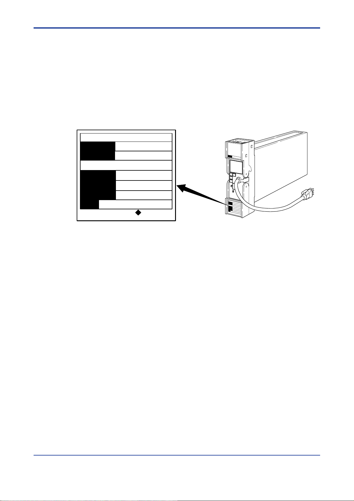
Check of Model and Suffix Codes
The model and suffix codes are indicated on the Name plate attached to the front cover
of the instrument. Crosscheck this information with the model and suffix codes of Section 2.2 to ensure that the product is as specified in the order.
ALARM UNIT
MODEL
SUFFIX
SKYD
-204*R
1-2
SUPPLY
INPUT
MODEL
80-138VAC 47-63 Hz
/20-130VDC 90mA AT 20VDC
1〜5 VDC
TypeK
NO.
YOKOGAWA
Yokogawa Electric Corporation
Figure 1-1 Name Plate
Confirmation of the Package Contents
Check the package contents against the list below. If anything is missing or damaged,
immediately contact the sales office from which you purchased the product or your
nearest Yokogawa representative.
z SKYD Alarm Unit ............................................................................................ 1
z Alarm Label (Parts No.: L4040JA).................................................................. 1 sheet
z Fuse (Parts No.: S9510VK)............................................................................ 1
z User’s Manual (This manual).......................................................................... 1
Made in Korea
IM 01B04K01-02E 10th Edition : 2004.05.01-00
Page 7

<Toc> <1. INTRODUCTION>
1.2 Documentation Conventions
This manual uses the following notational conventions.
Symbols
The following symbols are used in this manual.
WARNING
Indicates that operating the hardware or software in a particular manner may damage it
or result in a system failure.
NOTE
Draws attention to information that is essential for understanding the operation and/or
features of the product.
TIP
Gives additional information to complement the present topic and/or describes terms
specific to this document.
See Also
Gives reference locations for further information on the topic.
Description of Displays
Some of the representations of product displays shown in this manual may be exaggerated, simplified, or partially omitted for reasons of convenience when explaining them.
1-3
1.3 Notice
This User’s Manual
z This manual should be passed on to the end user. Keep at least one extra copy of
the manual in a safe place.
z Read this manual carefully to gain a thorough understanding of how to operate this
product before you start using it.
z This manual is intended to describe the functions of this product. Yokogawa Electric
Corporation (hereinafter simply referred to as Yokogawa) does not guarantee that
these functions are suited to the particular purpose of the user.
z Under absolutely no circumstances may the contents of this manual, in part or in
whole, be transcribed or copied without permission.
z The contents of this manual are subject to change without prior notice.
z Every effort has been made to ensure accuracy in the preparation of this manual.
Should any errors or omissions come to your attention however, please contact your
nearest Yokogawa representative or sales office.
IM 01B04K01-02E 10th Edition : 2004.05.01-00
Page 8

<Toc> <1. INTRODUCTION>
Protection, Safety, and Prohibition against Unauthorized Modification
z In order to protect the product and the system controlled by it against damage and
ensure its safe use, make certain that all of the instructions and precautions relating
to safety contained in this document are strictly adhered to. Yokogawa does not guarantee safety if products are not handled according to these instructions.
z The following safety symbols are used on the product and in this manual.
If this symbol is indicated on the product, the operator should refer to the explanation
given in the user’s manual in order to avoid personal injury or death to either themselves or other personnel, and/or damage to the instrument. The manual describes
that the operator should exercise special care to avoid shock or other dangers that
may result in injury or loss of life.
Protective ground terminal:
This symbol indicates that the terminal must be connected to ground prior to operating the equipment.
1-4
Function ground terminal:
This symbol indicates that the terminal must be connected to ground prior to operating the equipment.
AC voltage:
This symbol indicates that AC voltage is present.
DC voltage:
This symbol indicates that DC voltage is present.
z Do not turn off the power of the product during adjustment.
z Be sure to confirm the parameters such as alarm set point referring to ''5.4 Parameter
List'' before installing the product in a system or plant. After confirming them, install
the product in a system or plant and turn on the power.
z If protection/safety circuits are to be used for the product or the system controlled by
it, they should be externally installed on the product.
z When you replace the parts or consumables of the product, only use those specified
by Yokogawa .
z Do not modify the product.
Force Majeure
z Yokogawa does not make any warranties regarding the product except those men-
tioned in the WARRANTY that is provided separately.
z Yokogawa assumes no liability to any party for any loss or damage, direct or indirect,
caused by the use or any unpredictable defect of the product.
IM 01B04K01-02E 10th Edition : 2004.05.01-00
Page 9

<Toc> <1. INTRODUCTION>
1-5
1.4 About Compatibility with the Conventional Model (Style A)
z The operation and function differ from the conventional model.
Read this manual carefully to gain a thorough understanding of how to operate this
product before you start using it.
z Be sure to confirm the parameters such as Alarm set point and setting jumper refer-
ring to ''5. Setting'' before installing the product in a system or plant. After confirming
them, install the product in a system or plant and turn on the power.
IM 01B04K01-02E 10th Edition : 2004.05.01-00
Page 10

<Toc> <1. INTRODUCTION>
Blank Page
1-6
IM 01B04K01-02E 10th Edition : 2004.05.01-00
Page 11
<Toc> <2. GENERAL>
2. GENERAL
The Model SKYD Alarm Unit provides two types of alarms : absolute alarm that is
output after comparison of one input signal with one or two alarm set points, and
deviation alarm that is output after comparison of the deviation between two
inputs with two alarm set points.
Direct or reverse alarm action can be selected for each of the alarm output set
points. The front panel is provided with an alarm LED indicator lamp for
confirming alarm relay action (when relay is energized).
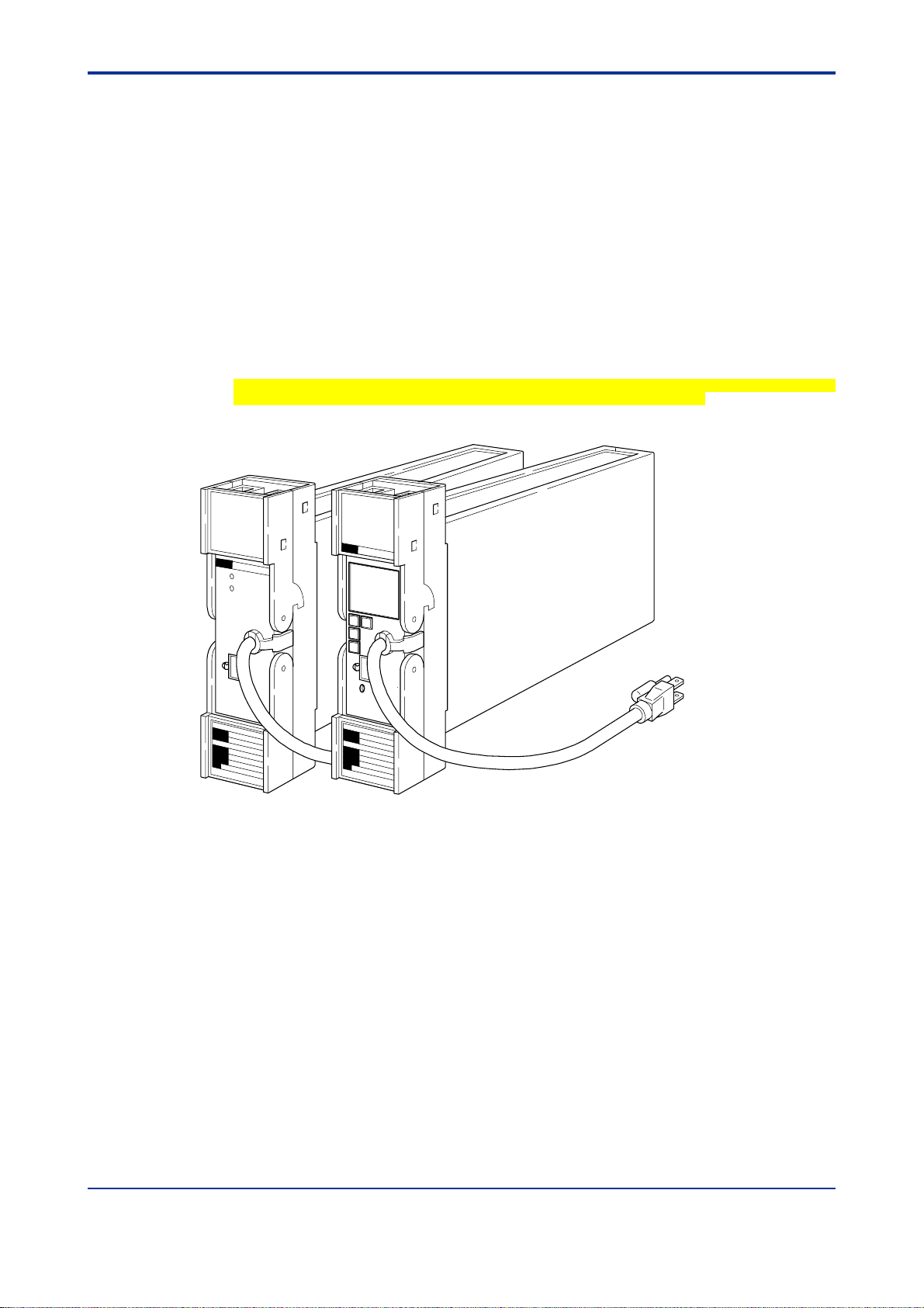
The JHT200 Handy Terminal
On the SKYD model with display setter (SKYD-x04), input indication (engineering
unit) can be displayed and alarm set points can be displayed / set on the front
panel.
*1: The modular jack conversion adapter (E9786WH) is required for connecting the JHT200 Handy Terminal to the
Alarm Unit.
The 5 pin-connector type communication cable (F9182EE) and modular jack conversion adapter (E9786WH) is
required for connecting the BT200 BRAIN Terminal of YOKOGAWA ELECTRIC Corporation
(*1)
is used for setting the SKYD parameters.
2-1
Figure 2-1 External View
IM 01B04K01-02E 10th Edition : 2004.05.01-00
Page 12

<Toc> <2. GENERAL>
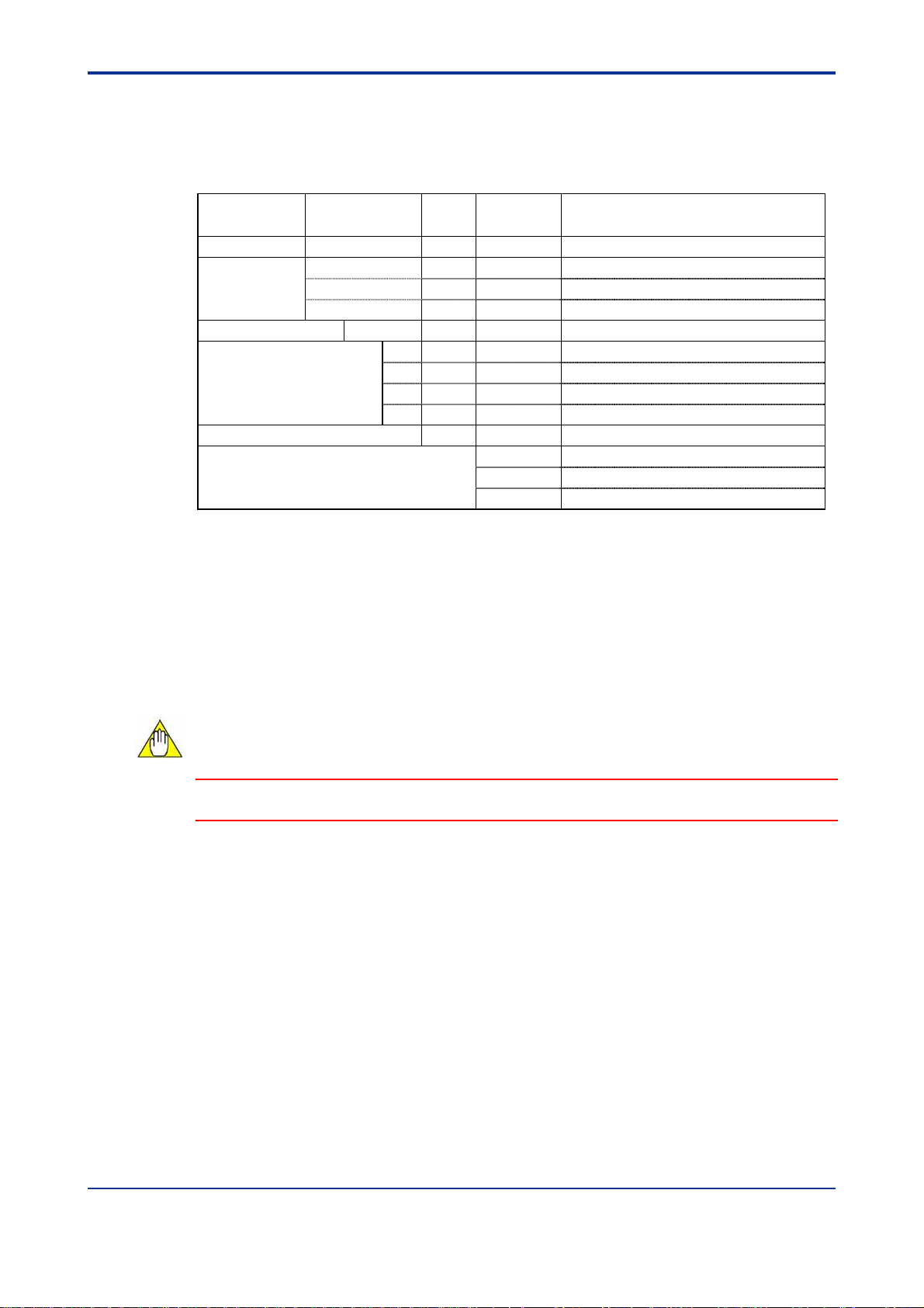
2.1 Standard Specifications
The following table shows the SKYD standard specifications.
Table 2-1 Standard Specifications
Item Description
Input Signal 1 to 5 V DC Input resistance: 1MΩ
Number of Input 1 or 2 inputs (as per sales order)
Output Signal Relay contacts (NO and NC contacts)
Contact Capacity: 100 V AC, 1 A (resistive load)
220 V AC, 0.5 A (resistive load)
110 V DC, 0.1 A (resistive load)
30 V DC, 1 A (resistive load)
Contact service life: 600,000 times
Number of Output 1 or 2 outputs (as per sales order)
Alarm Action Direct or Reverse
(1) Input absolute alarm
1-input and 1-set point, or 1-input and 2-set point
(2) 2-input deviation alarm
2-input and 2-setpoint
Hysteresis and ON/OFF delay can also be set.
Alarm Setting and
Accuracy
Warranty Range
Setting Accuracy ±0.2% of span (±0.5% of span for the version with square root characteristic)
Power Supply AC or DC (no change to instument)
Power
Consumption
Ambient
Temperature and
Ambient Humidity
Mounting Indoor, rack mounting
Weight 1.7 kg
Setting method: By display setter on the front panel (SKYD-x04 only)
By JHT200 Handy Terminal (sold separately)
Alarm setting/accuracy warranty range
Absolute alarm: 0 to 100% of input signal
2-input deviation alarm: -100 to +100% of deviation signal
100 V version DC: 20 to 130 V (no polarity)
AC: 80 to 138 V, 47 to 63 Hz
200 V version DC: 120 to 340 V (no polarity)
AC: 138 to 264 V, 47 to 63 Hz
SKYD-10x 24 V DC, 50 mA
100 V AC, 4.8 VA
220 V AC, 8.0 VA
SKYD-20x
SKYD-30x
0 to 50°C, 5 to 90%RH (non-condensing)
24 V DC, 70 mA
100 V AC, 5.8 VA
220 V AC, 8.7 VA
2-2
IM 01B04K01-02E 10th Edition : 2004.05.01-00
Page 13
<Toc> <2. GENERAL>
2.2 Model and Suffix Codes
The following table shows the SKYD model and suffix codes.
Table 2-2 Model and Suffix Codes
Model Suffix Codes Style
SKYD Alarm Unit
Alarm
0 Always 0
Setting Scale (*1)
Style Code *R Style R
Option
*1: In the case of 2-set point, the setting ranges of set point 1 / set point 2 are the same.
*2: The value obtained by squaring the set point functions as the alarm set point.
*3: 2-input deviation alarm only
-1 1-input, 1-set point absolute alarm
-2 1-input, 2-set point absolute alarm
-3 2-input, 2-set point deviation alarm
0 0 to 100 linear
1 0 to 10 square root (*2)
2 -100 to 0 to +100 linear (*3)
4 Actual scale (with display setter)
Optional
Suffix Codes
/A2ER 220 V power supply
/NHR Without case
/TB Power supply terminal type
Description
2-3
2.3 Accessory
Fuse 1 A: 1
Alarm Label: 1 sheet
NOTE
The fuse (S9510VK) is the dedicated fuse, Do not use it for other products.
IM 01B04K01-02E 10th Edition : 2004.05.01-00
Page 14

<Toc> <2. GENERAL>
Blank Page
2-4
IM 01B04K01-02E 10th Edition : 2004.05.01-00
Page 15
<Toc> <3. INSTALLATION>
3. INSTALLATION
For details of the installation procedure and wiring precautions, refer to the
technical information “YEWSERIES 80 Installation Manual” (TI 1B4A9-01E) or the
instruction manual “Installation of Rack-Mounted Instruments” (IM 1B4F2-01E).
3.1 External Wiring
(a) All cable ends must be furnished with crimp-on type solderless lugs (for 4mm
screws)..
(b) Draw out the internal unit from the rack case.
(c) Connect the cables to the correct terminals referring to Figure 3-1.
(d) Return the internal unit into the rack case after completing the wiring.
(e) Always return the terminal block cover to its original position after completing the
wiring.
NOTE
3-1
The terminal block cover cannot be returned to its original position if the internal unit is
not installed its original position in the rack case. Securely return the terminal block
cover because it also functions as lock for the internal unit.
J K
B
A
Front view
may differ
according
to device.
1
2
C
H
D
F
5
3
4
6
7 8
*1: Not provided for SKYD-10x.
*2: SKYD-30x only.
Note: When output is not used, the terminals are opened.
COM: Common
NC: Contact closes when relay is de-energized
NO: Contact opens when relay is de-energized
Figure 3-1 Terminal Layout and Terminal Wiring
Terminal
Designation
A NC Alarm output 1
B COM
C
D
F NC Alarm output 2(*1)
H COM
J NO
K NO
1 +
2 3
4
5 +
6 7
8
Input (1 to 5 V DC)
Input 2 (1 to 5 V DC) (*2)
Description
IM 01B04K01-02E 10th Edition : 2004.05.01-00
Page 16
<Toc> <3. INSTALLATION>
3.2 Example of Alarm Wiring
The SKYD alarm unit provides various types or alarms depending on the setting of the
alarm action or the method of connecting the alarm output terminals. Thus, the
necessary wiring should be made with reference to the following two examples:
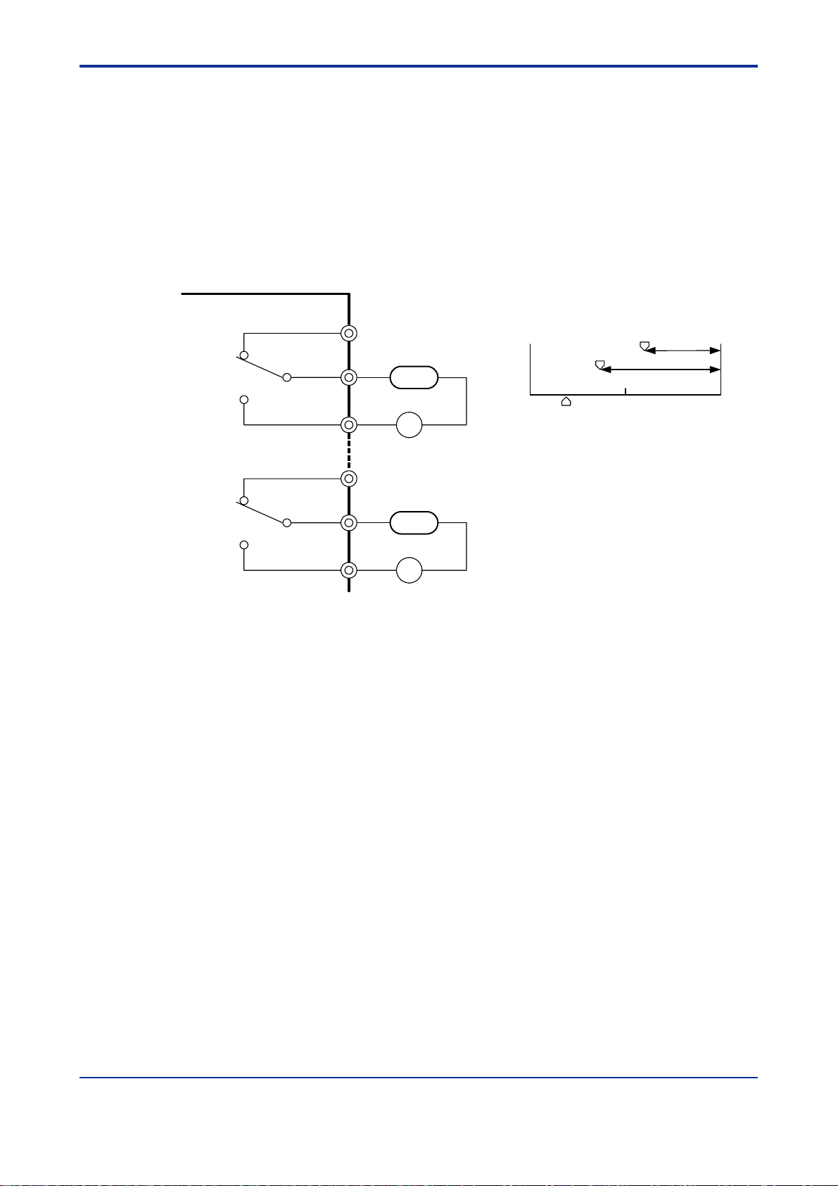
3.2.1 High-limit and High-high-limit Alarms
Set the direct action (DIRECT) for the alarm actions of both alarms 1 and 2. Then wire
the terminals as illustrated in Figure 3-2.
SKYD Alarm Unit
A
B
H
0
(-100)
Alarm 2 setting
Alarm 1 setting
3-2
100
(100)
HH
H
J
AC
F
H
K
AC
Alarm output terminal
Figure 3-2 External Wiring - Example 1
HH
Input (deviation)
value
50
(0)
IM 01B04K01-02E 10th Edition : 2004.05.01-00
Page 17
<Toc> <3. INSTALLATION>
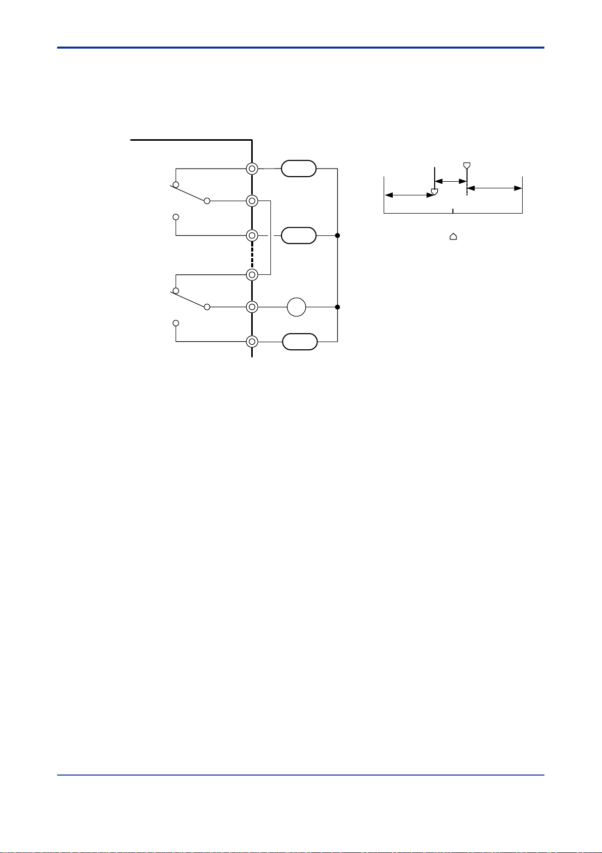
3.2.2 Three-position Alarm
Set the reverse action (REVERSE) for the alarm action of alarm 1, and the direct action
(DIRECT) for the alarm action of alarm 2. Then wire the terminals as illustrated in Figure
3-3.
3-3
SKYD Alarm Unit
Alarm output terminal
Figure 3-3 External Wiring - Example 2
Applicable Cables
(1) Signal circuit wiring
• Cross-sectional area of the cable conductor: 0.5 to 0.75 mm
• Examples of applicable cables: Single core PVC insulated flexible cable (VSF)
(2) Alarm circuit wiring
• Cross-sectional area of the cable conductor: 0.5 to 1.25 mm
• Examples of applicable cables: 600 V PVC insulated cable (IV) stranded wires (JIS
(3) Power supply wiring
• Cross-sectional area of the cable conductor: 1.25 to 2.00 mm
• Examples of applicable cables: 600 V PVC insulated cable (IV) stranded wires
A
N
0
(-100)
B
J
L
Alarm 2 setting
N
L
Alarm 1 setting
50
(0)
Input (deviation) value
100
(100)
H
F
H
AC
K
H
Alarm
2
stranded wires (JIS C 3306);
heat-resistant vinyl-insulated cable (UL style 1007)
2
C 3307);
PVC insulated cable for electric appliances (KIV)
stranded wires (JIS C 3316);
heat-resistant vinyl-insulated cable (UL style 1007)
2
(JIS C 3307)
IM 01B04K01-02E 10th Edition : 2004.05.01-00
Page 18

<Toc> <3. INSTALLATION>
Blank Page
3-4
IM 01B04K01-02E 10th Edition : 2004.05.01-00
Page 19
<Toc> <4. PRINCIPLES OF OPERATION>
4. PRINCIPLES OF OPERATION
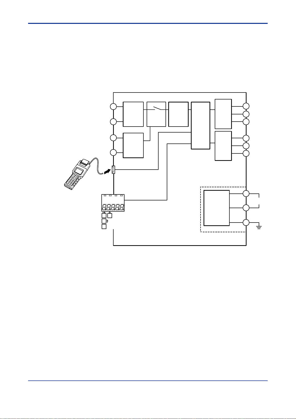
4.1 Principle of Operation
Input signals are converted to digital data by the A/D conversion circuit. The resulting
digital data is processed (square root calculation, etc.) by the microcomputer, and the
alarm relay is then energized/de-energized by alarm calculation processing (comparison,
etc.).
4-1
1
2
5
6
Handy
Terminal
SET
Input
processing
circuit 1
Input
processing
circuit 2
(*1)
Display setter (*2)
*1: SKYD-30x only
*2: SKYD-x04 only
*3: Except SKYD-10x
Multiplexer
Figure 4-1 Hardware Function Block Diagram
A/D
conversion
circuit
Micro-
processor
Relay
output 1
Relay
output 2
(*3)
Power
supply circuit
A
B
J
F
H
K
L+
Power
supply
N−
GND
IM 01B04K01-02E 10th Edition : 2004.05.01-00
Page 20
<Toc> <4. PRINCIPLES OF OPERATION>
4.2 Description of Functions
The following describes the functions of the SKYD-10x/20x and SKYD-30x.
4.2.1 SKYD-10x/20x Functions
Input signal
A/D conversion
1 to 5 VDC
Normalization
INPUT1
4-2
Square root calculation
Scaling (*1)
Bias (*1)
PV1
Alarm detection 1
Alarm relay connection 1
LINEARIZE1
LOW CUT1
BIAS1
SET POINT1
HYSTERESIS1
ALM1 ACTION
ON DELAY1
OFF DERAY1
RLY1 ACTION
RLY1 TEST
SCH1
SCL1
DP1
*1: SKYD- 04 only
□
SKYD-20 only
□
Alarm detection 2
Alarm relay connection 2
SET POINT2
HYSTERESIS2
ALM2 ACTION
ON DELAY2
OFF DERAY2
RLY2 ACTION
RLY2 TEST
Relay output 1 Relay output 2
Figure 4-2 Software Function Block Diagram
The alphabet codes in the figure are the names of BRAIN communication parameters.
IM 01B04K01-02E 10th Edition : 2004.05.01-00
Page 21

<Toc> <4. PRINCIPLES OF OPERATION>
z Explanation of Input processing block
• A/D conversion:
Performs A/D conversion on input signals.
• Normalization:
A/D-converted signals are converted to a scale of 1 to 5 V DC. (INPUT1)
• Square root calculation (LINEARIZE1):
When square root calculation is set to ON, the input processing block performs
square root calculation on the input signal.
The low-cut point (LOW CUT1) can be set to the square root calculation. The figure
below shows operation when the input signal is near the low-cut point. This low-cut
point is provided with a hysteresis of 0.2%.
Input after low-cut processing
(Y)
5V
4-3
X - 1 + 1
≤1V: Y=X
5V
Input (X)
1V
1V
Hysteresis fixed at 8 mV (0.2%)
Low-cut point
Y = 2 x
X = Y Y,X: 1 to 5 (V)
When X
• Scaling (SKYD-x04 only):
The display in engineering unit is available according to the SCH1, SCL1 and DP1
parameter settings.
The value after scaling (or, when the bias function is used, the value obtained by
adding bias to this value) becomes PV1.
SCH1, SCL1, DP1 setting (default: 0.0 to 100.0)
<Setting Method>
(1) Set the decimal point position matched to the unit system actually in use at DP1.
(Example: two digits past the decimal point)
(2) Register the measuring input scale range at SCH1 and SCL1.
(Example: SCH1=20.00, SCL1=0.00)
(Example)
1V 5V
0.0 (SCL1) 100.0 (SCH1)
0.00 (SCL1) 20.00 (SCH1)
Decimal point position registered at DP1.
Default scale
Measuring input scale
(after scaling)
IM 01B04K01-02E 10th Edition : 2004.05.01-00
Page 22

<Toc> <4. PRINCIPLES OF OPERATION>
NOTE
Reverse scaling (SCH1 < SCL1) is also possible.
A setting error occurs when SCH1 is set to equal SCL1.
• Bias:
A bias value (BIAS1) can be added to scaling values.
This allows error to be compensated when there is an error between the input value
and the indicated value.
Bias can be set within the range ±10% [(SCH1 - SCL1) x 0.1] of the scaling width.
The input value displayed on the display setter on the front panel (PV1 in the
BRAIN communications parameter) is the value after addition of bias.
z Explanation of Alarm detection block
In the following description, n is "1" for SKYD-10x, and "1" or "2" for SKYD-20x.
• Alarm detection n:
Performs alarm detection.
• ALMn ACTION: Alarm action
Direct .................. The alarm state is entered when the input value exceeds the
preset alarm set point.
Reverse...............The alarm state is entered when the input value is at the preset
alarm value or lower.
• SET POINTn: Alarm set point
• HYSTERESISn: Alarm hysteresis
• ON DELAYn: Alarm ON delay
Sets the dead time until the alarm turns ON.
An alarm state is entered when the input value is in the alarm range for the duration
set at ON DELAYn.
If input returns to the normal range before the time set at ON DELAYn is reached,
the alarm does not turn ON.
• OFF DELAYn: Alarm OFF delay
Sets the dead time until the alarm turns OFF.
A normal state is entered when the input value is in the normal range for the
duration set at OFF DELAYn.
If input returns to the alarm range before the time set at OFF DELAYn is reached,
the alarm does not turn OFF.
4-4
NOTE
• When the ON delay/OFF delay settings are changed during a delay, delay action is
discontinued, the current alarm or normal state is returned to, and the delay action is
performed from that state.
• The alarm function does not work for 3 seconds after power ON.
IM 01B04K01-02E 10th Edition : 2004.05.01-00
Page 23

<Toc> <4. PRINCIPLES OF OPERATION>
z Relay output block
• RLYn ACTION: Alarm relay action
Energized at normal operation............ The relay is energized when the alarm
detection result is a normal state.
De-energized at normal operation....... The relay is energized when the alarm
detection result is an alarm state.
• RLYn TEST: Relay action test
This function is for testing relay action.
Relays can be turned ON/OFF without influencing the currently alarm detection
result.
4.2.2 SKYD-30x Functions
4-5
Input signal 1
A/D conversion
Normalization
INPUT1
Square root calculation (*1)
Scaling (*1)
Bias (*1)
PV1
Deviation (subtraction)
INPUT DEV
Alarm detection 1
Alarm relay connection 1
Relay output 1 Relay output 2
1 to 5 VDC
BIAS1
*1: SKYD-304 only
LINEARIZE1
LOW CUT1
SCH1
SCL1
DP1
SET POINT1
HYSTERESIS1
ALM1 ACTION
ON DELAY1
OFF DERAY1
RLY1 ACTION
RLY1 TEST
INPUT2
Input signal 2
A/D conversion
Normalization
Square root calculation (*1)
Scaling (*1)
Bias (*1)
PV2
Alarm detection 2
Alarm relay connection 2
1 to 5 VDC
BIAS2
*1: SKYD-304 only
HYSTERESIS2
ALM2 ACTION
OFF DERAY2
SET POINT2
ON DELAY2
RLY2 ACTION
RLY2 TEST
Figure 4-3 Software Function Block Diagram
The alphabet symbols in the figure are the names of BRAIN communication parameters.
In the following descriptions, n is "1" or "2".
z Input processing block
Functions are the same as SKYD-10x/20x except that there are two inputs.
• Input deviation processing block
Input deviation INPUT DEV is the value of "PV1 - PV2".
z Alarm detection block
Functions are the same as SKYD-20x except that the detection target is input
deviation INPUT DEV.
z Relay output block
Functions are the same as SKYD-20x.
IM 01B04K01-02E 10th Edition : 2004.05.01-00
Page 24

<Toc> <4. PRINCIPLES OF OPERATION>
4.3 Example of Alarm Function Setting
This section describes the alarm function setting showing the example using the alarm
function parameters.
4.3.1 Condition of Alarm Function
Set the following conditions.
(1) Condition for Alarm 1
The alarm is output when the status where the input value is 80% or more continues
for 1 second or more.
The alarm is released when the status where the input value is 70% or less
continues for 2 seconds or more.
(2) Condition for Alarm 2
The alarm is output when the input value is 15% or less.
The alarm is released when the input value is 20% or more.
4.3.2 Parameters of Alarm Function
The table below shows the parameters the condition of alarm function described in 4.3.1
is placed to.
Table 4-1 Table of Parameter Setting Example for Alarm 1 and Alarm 2 (SKYD-20x)
Item
Parameter Set point Parameter Set point
Alarm set point E01: SET POINT1 80% E02: SET POINT2 15%
Direction of alarm
E07: ALM1 ACTION DIRECT E08: ALM2 ACTION REVERSE
action
Alarm hysteresis E09: HYSTERESIS1 10% E10: HYSTERESIS2 5%
Alarm ON delay E15: ON DELAY1 1 s E16: ON DELAY2 0 s
Alarm OFF delay E17: OFF DELAY1 2 s E18: OFF DELAY2 0 s
Alarm 1 Alarm 2
4-6
4.3.3 Operating Condition of Alarm Function
Refer to the following figure for operating condition of alarm 1 and alarm 2.
[℃]
Alarm condition established
100
Alarm-1 set point >
Alarm-2 set point >
Alarm-1 Direct
action
Alarm-2 Reverse
action
80
60
40
20
Alarm-2 hysteresis (5%)
15
0
De-energized
Figure 4-4 Alarm Action
Alarm-released condition established
1 s 2 s
Alarm condition established
Energized
De-energized
Alarm-1 hysteresis (10%)
Alarm-released condition established
De-energized
Energized De-energized
Elapsed time (s)
IM 01B04K01-02E 10th Edition : 2004.05.01-00
Page 25

<Toc> <5. SETTING>
5. SETTING
Items to Confirm before Start of Operation
Before you start operation, inspect and confirm the following items:
(1) Draw out the internal unit from the rack case, and make sure that the specified fuses
are properly mounted in the fuse holders at the rear of the internal unit.
(2) When inserting the internal unit into the rack case, firmly connect the multi-pin
connectors for connecting the internal unit and the case.
(3) Make sure that power plugs are properly connected to the power outlet.
(4) Make sure that external wiring to the terminal block is properly connected.
NOTE
Refer to Section 7.2, “Action in Fault Condition” for how to detect device error by alarm
output.
5-1
IM 01B04K01-02E 10th Edition : 2004.05.01-00
Page 26

<Toc> <5. SETTING>
5.1 Names of Components
The following shows the names of SKYD components.
Alarm 1,2 relay action indicator lamps (ALM1,2)
ALM SP
1
2
Alarm 1,2 set point indicator lamps (SP1,2)
12
Display setter
Data digit feed key
Parameter selection key
5-2
Tag plate
Alarm 1,2 relay action indicator lamps (ALM1,2)
BRAIN connector (w/ cover)
Key setting enable switch
(ENBL switch)
Name plate
SKYD- 01
x
x
SKYD- 02
xx
SKYD- 03
SKY D- 04
Output terminal block
SET
Main board
Data change key
Data setting fix key
SET
Terminal block cover/handle
for drawing out internal unit
Rack case
Input terminal block
Multi-pin connector
Power plug
Figure 5-1 Names of Components
IM 01B04K01-02E 10th Edition : 2004.05.01-00
Page 27

<Toc> <5. SETTING>
5.2 Setting Jumper
The SKYD is provided with the following jumpers.
Other SKYDs excluding the SKYD-x04 are not provided with the ALM1, 2 jumpers.
Jumper Code Jumper Name Except SKYD-x04 SKYD-x04
W.P. Parameter Write Protect Available Available
ALM1 Alarm 1 action setting jumper Not available Available
ALM2 Alarm 2 action setting jumper
(except SKYD-10x)
• Parameter Write Protect jumper
When this jumper is set to ON, changing of parameters by the key switches and
Handy Terminal is disabled. "LOC" will be displayed on the display setter if the ""
switch is pressed with the SP1 or SP2 parameter displayed on the display setter.
To cancel the "LOC" display and return to the previous display, press any key.
• Alarm action setting jumper
This jumper is for setting the direction of alarm action.
The table below shows the relationship between direction of alarm action and
direction of relay action.
Direction of alarm relay action: De-energized at normal operation
Not available Available
5-3
ALMn Direction of alarm action Input value < Set point Set point < Input value
DIR Direct (high-limit alarm) Output relay de-energized Output relay energized
RVS Reverse (low-limit alarm) Output relay energized Output relay de-energized
Direction of alarm relay action: Energized at normal operation
ALMn Direction of alarm action Input value < Set point Set point < Input value
DIR Direct (high-limit alarm) Output relay energized Output relay de-energized
RVS Reverse (low-limit alarm) Output relay de-energized Output relay energized
IM 01B04K01-02E 10th Edition : 2004.05.01-00
Page 28

<Toc> <5. SETTING>
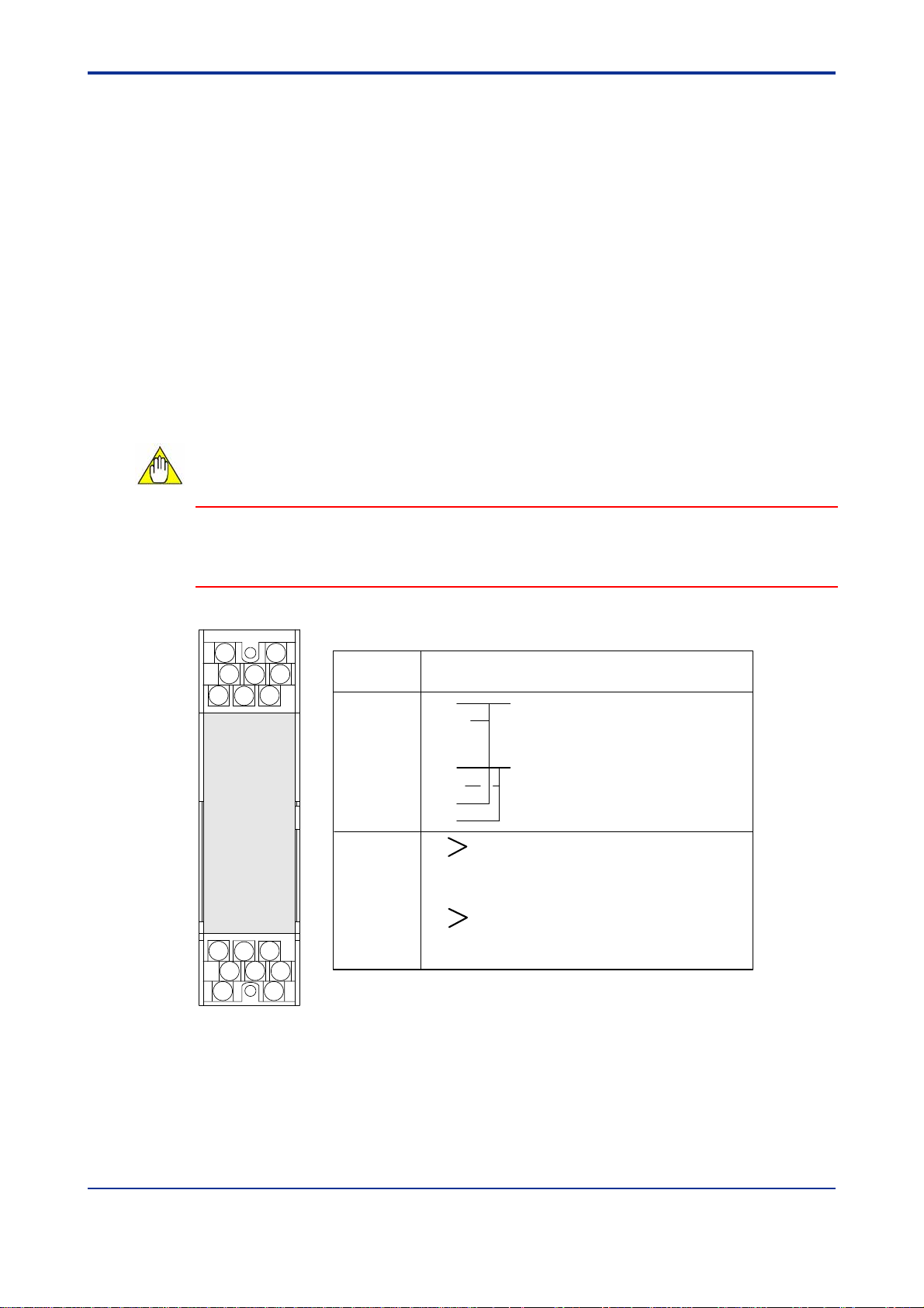
5.2.1 Check of Setting Jumper and its Location
The setting jumpers are located on the main board of the internal unit.
Draw out the internal unit, and check the current jumper settings.
Current jumper settings can also be checked on the JHT200 Handy Terminal.
Jumper Name Parameter Name
Parameter Write Protect
Direction of alarm 1 action
Direction of alarm 2 action (except SKYD-10x)
A55:WRT PROTECT
E07:ALM1 ACTION
E08:ALM2 ACTION
5-4
Parameter Write
Protect
ON disables
changing of
parameters.
Direction of alarm
action
Direct
action
selected
Reverse
action
selected
Setting jumpers
(factory-set default)
Figure 5-2 Setting Jumper
5.2.2 Change of Setting Jumper
Follow the procedure below to change the setting jumpers:
(a) Pull the terminal block cover toward you to draw out the internal unit from the rack
case.
(b) Check the jumpers on the main board of the internal unit, and change their settings
as desired. Use tweezers or another fine-tipped object to change the setting jumpers.
(c) Return the internal unit to the rack case.
(d) Return the terminal block cover to its original position.
IM 01B04K01-02E 10th Edition : 2004.05.01-00
Page 29

<Toc> <5. SETTING>
5.3 Setting of Parameters
5-5
This instrument has BRAIN communication parameters for specifying functions and
adjusting input. Connect JHT200 Handy Terminal
(*1)
to the instrument to display or set
parameters (modular jack conversion adapter (E9786WH) is required )
On the SKYD model with display setter (SKYD-x04), input indication (engineering unit)
can be displayed and alarm set points can be display/set on the front panel.
For details on parameters, refer to the Parameter Lists.
*1: BT200 BRAIN Terminal of YOKOGAWA ELECTRIC Corporation can also be used.
5.3.1 Parameter Change Disable Function
The SKYD is provided with a parameter change disable function for preventing
parameter settings from being changed by operator error.
Table 5-1 Parameter Change Disable Function
Disable Setting Method Disable Cancel Method Description of Disable Operation
Parameter
Write Protect
jumper
Enable
switch
(SKYD-x04
only)
Set W.P. jumper on the main
board to "ON".
Changes cannot be made if no
settings are made for 30
minutes after operating any key
switch on the front panel in a
setting change enable state.
Set W.P. jumper on the
main board to "OFF".
Press the Enable switch. y Changing of parameter setting by
y Changing of parameter setting by
key switches.
y Changing of parameter setting by
Handy Terminal.
key switches.
5.3.2 Setting of Parameters Using Display Setter (SKYD-x04)
On the SKYD-x04, you can change alarm set point using the display setter on the front
panel.
Other parameters are changed using the JHT200 Handy Terminal.
The table below describes the relationship between key switch operations and migration
of display states.
Table 5-2 Relationship between Key Switch Operations and Migration of Display
States
Switch
Display Mode Setting Change Mode Setting Fix Mode Indicator Out Mode
△
→
↑
SET No operation
ENBL
Displays the next
parameter.
Advances to the setting
change mode when a
settable or changeable
parameter is displayed in
the setting change enabled
state.
Displays the next
parameter.
Enters setting change enable state.
Enable switch is disabled if the Parameter Write Protect jumper is set to "ON".
*1: When the Parameter Write Protect jumper on the main board is set to "ON", the SKYD will not advance to the setting
(*1)
change mode. In this state, "LOC" is displayed on the display setter.
Display Function Key
Cancels the newly
changed values,
returns to the display
mode, and displays
the next parameter.
Moves setting digit.
Changes the set point. No operation
Advances to the
setting fix mode.
Cancels the newly
changed values, returns
to the display mode, and
displays the next
parameter.
Returns to the setting
change mode, and
moves to the next digit.
Fixes the set point, and
advances to the display
mode.
This mode is
entered if no key
switches are
operated for 30
minutes when the
display mode
parameter is set to
"OFF".
The display mode is
returned to if any
key switch is
pressed in the
indicator out mode.
IM 01B04K01-02E 10th Edition : 2004.05.01-00
Page 30

<Toc> <5. SETTING>
Indicator out mode is
entered if no key switch is
operated for 30 minutes
when display mode
parameter is "OFF".
Indicator out mode Display mode
Display mode is returned to
when any key switch is
pressed.
Cancels new set point
value, returns to display
mode, and displays next
parameter.
Setting fix mode Setting change mode
(all digits flashing)
△
SET
Fixes set point, and moves
to display mode.
Moves to setting fix
mode.
Returns to setting change
→
mode, and moves to next digit.
↑
Displays previous parameter.
△
Displays next parameter.
→
Moves to setting
change mode.
SET
△
(1digitflashing)
→
Feeds digit.
↑
Increments value.
Cancels new set point,
returns to display mode,
and displays next
parameter.
Figure 5-3 Key Switch Operations and Migration of Display States
5-6
Switching the Display
Each press of the △ key switches the display data.
ALM
Power on
Input value (PV1) is
displayed.
ALM/SP lamps out
In this example,
"40.00"
Figure 5-4 Progression of Display Screen
LED Indicator Lamps
Press △ key.
ALMSP
1 2 1 21 2 1 2 1 2
SP
Press △ key.
Alarm 1 set point (SP1)
is displayed.
SP1 lamp lit
In this example,
"50.00"
ALM
SP
1 2
Press △ key.
Alarm 2 set point (SP2)
is displayed.
SP2 lamp lit
In this example,
"30.00"
The table below lists the type of LED indicator lamps on the front panel and their lighting
conditions.
LED Lamp Color Lighting Conditions Remarks
ALM1 Yellow Lit when alarm 1 output relay is energized
ALM2 Yellow Lit when alarm 2 output relay is energized SKYD-20x, -30x only
SP1 Green Lit when alarm 1 set point (SP1) is displayed on
the display setter
SP2 Green Lit when alarm 2 set point (SP2) is displayed on
the display setter
IM 01B04K01-02E 10th Edition : 2004.05.01-00
SKYD-x04 only
SKYD-204, -304 only
Page 31

<Toc> <5. SETTING>
Setting Parameters
Display the desired parameter (e.g. alarm set point), and follow the procedure below to
change its set point.
ALM SP
1
2
12
(1) Input value (60.00) is displayed at power ON.
5-7
SET
ALM SP
1
2
SET
12
Press the - key. The SP1 lamp lights, and the alarm 1 set point is displayed.
→
(2) The alarm 1 set point (80.00) is displayed.
Press the - key. In the case of the SKYD-104, the SP1 lamp goes out, and the
→
input value is displayed.
In the case of the SKYD-204/304, the SP2 lamp lights, and
→
the alarm 2 set point is displayed.
ALM SP
1
2 12
Alarm 2 set point (30.00) is
displayed. (SKYD-204/304 only)
(3) Press the ENBL switch to enter setting change enable state.
(4) Set the alarm set point. (Change the alarm 1 set point to "70.00" from "80.00".)
Alarm set points whose SP lamp is lit can be changed.
Press the - key.
The uppermost digit on the display flashes.
→
Hold down the key to move the flashing section to the digit
on the right.
Press the - key.
This increments the value at the flashing digit. Hold down the
→
key to feed the value to "7".
Press the - key.
SET
All parameter digits flash. Pressing the key again
→
SET
causes "70.00" to light. (This fixes the new parameter
settings.).
Figure 5-5 Setting Parameters
NOTE
When the Parameter Write Protect jumper on the main board is set to "ON", the SKYD
will not advance to the setting change mode. In this state, "LOC" is displayed on the
display setter.
IM 01B04K01-02E 10th Edition : 2004.05.01-00
Page 32

<Toc> <5. SETTING>
Display at Power ON
The model with display setter displays REV NO. (revision number of software for the
SKYD) for about 3 seconds after power ON.
Example of display (REV NO.2)
LOC Display
When "LOC" is displayed, this indicates that parameter settings cannot be changed.
(The Parameter Write Protect jumper on the main board is set to "ON".)
To cancel the "LOC" display and return to the previous display, press any key.
Indicator Out Mode Display
In this mode, only the decimal point is displayed on the display setter.
When the display mode parameter (DSP MODE) is set to "OFF", and no key operation is
performed for 30 minutes, the SKYD moves to the indicator out mode.
To cancel this mode and return to the display mode, press any key switch.
I/O signal processing and calculations are performed as usual even in the indicator out
mode.
If the self check discovers an error (A/D conversion error, EEPROM error,
EEPROMSUM error) in the indicator out mode, this mode is canceled, and the error is
displayed. Also, the SKYD does not move to the indicator out mode when an error (A/D
conversion error, EEPROM error, EEPROMSUM error) occurs.
ALM SP
1 2 1 2
Press any key.
ALM SP
1 2 1 2
5-8
Moves to indicator
out mode if no key is
operated for 30
minutes.
Indicator out mode
Only decimal point is lit.
Figure 5-6 Indicator Out Mode
Normal operation
mode
IM 01B04K01-02E 10th Edition : 2004.05.01-00
Page 33

<Toc> <5. SETTING>
5.3.3 Setting of Parameters Using Handy Terminal
NOTE
For details of operation and adjusting procedures of JHT200 Handy Terminal, refer to
the instruction manual “JHT200 Handy Terminal” (IM JF81-02E).
5-9
<Connection>
JHT200
Handy Terminal
Figure 5-7 Connecting the Handy Terminal
Cable of 5-pin
connector type
(F9182EE)
BRAIN connector
Modular jack conversion adapter
(E9786WH)
IM 01B04K01-02E 10th Edition : 2004.05.01-00
Page 34

<Toc> <5. SETTING>
5.4 Parameter List
BRAIN communication parameters for SKYD are as follows.
On the SKYD-x04, only the input value can be displayed, and the alarm set point can be
displayed and set on the display setter on the front panel. Other, parameters are
displayed and set using the Handy Terminal.
5.4.1 SKYD-10x Parameter List
No. Parameter Name Symbol Description Display Conditions
Initial
display
01 Model Name MODEL Displays the model name.
02 Tag Number TAG NO
03 Self Check SELF CHK Displays the result (GOOD/ERROR) of the self check.
A Display 1 DISPLAY1
A01 Analog Input 1 INPUT1 Input value before input processing (square root or scaling)
A03 PV1 PV1 Input value (engineering unit) after input processing (square
A15 Alarm 1 Relay
Display
A54 Status Display STATUS Displays the value added to the value (Hex) indicating the
A55 Parameter Write
Protect
A56 Rev No. REV NO. Displays the device revision No.
A58 MENU REV MENU REV Displays the revision No. of the parameter group.
A60 Self Check SELF CHK Di splays the result (GOOD/ERROR) of the self check.
RLY1 STATUS Displays the state of the alarm 1 relay.
WRT PROTECT Displays the state of the Parameter Write Protect jumper.
Displays the tag number that is set.
(unit: V)
root or scaling)
DE-ENERGIZED: De-energized
ENERGIZED: Energized
self check result.
0000: Normal
0001: EEPROM error
0002: EEPROMSUM error
0004: Low input cut state
0008: Input range exceeded
0010: Setting error
0040: Power interruption during operation
1000: A/D conversion error
OFF: Setting of parameters enabled
ON: Setting of parameters disabled
Displayed on all
Displayed on all
Displayed on SKYD104
Displayed on all
5-10
IM 01B04K01-02E 10th Edition : 2004.05.01-00
Page 35

<Toc> <5. SETTING>
No. Parameter Name Symbol Description Setting Range Default Display Conditions
B Display 2 DISPLAY2
B01 Analog Input 1
B03 PV1
B15 Alarm 1 Relay
Display
B60 Self Check
D Setting Parameters SET(I/O)
D01 Tag Number 1 TAG NO.1 8 alphanumerics can be entered.
D02 Tag Number 2 TAG NO.2 8 alphanumerics can be entered.
D03 Comment 1 COMMENT1 8 alphanumerics can be entered.
D04 Comment 2 COMMENT2 8 alphanumerics can be entered.
D17 Linearization 1 LINEARIZE1 Specifies square root calculation
D19 Low Cut 1 LOW CUT1 Specifies low-cut point during
D40 Input Decimal Point
Position
D41 Input Scale L SCL1 Sets the conversion standard
D42 Input Scale H SCH1 Sets the conversion standard
D46 PV1 PV1 Displays the input value after
D47 Input 1 Bias BIAS1 Adds the bias value to the value
D51 Display Mode DSP MODE Selects the display setter state
D60 Self Check SELF CHK Result of self check
*1: Setting range is ±10% of span (EUS) after scaling. This range is initialized when SCH1 and SCL1 are changed.
Same as item A
ON/OFF.
square root calculation.
DP1 Sets the position of the decimal
point for the input scale (SCH1,
SCL1).
value at 1V input to scale and
display the input value in
engineering units.
value at 5V input to scale and
displays the input value in
engineering units.
input processing (scaling).
after input processing, and
displays as the PV1.
after 30 minutes elapses after a
key switch operation.
OFF: Power save mode
Only the decimal point is
displayed.
ON: Constant ON mode
Data is displayed at all
times regardless of
elapsed time.
(GOOD/ERROR) of the self
check.
Displayed on all
OFF
SQR
0.3 to 100.0 % 1.0 % Displayed when
#####.
####.#
###.##
##.###
-9999 to 9999
(engineering unit)
-9999 to 9999
(engineering unit)
-19999 to 32000
(engineering unit)
*1
OFF
ON
Displayed on all
OFF Displayed except on
SKYD-101
LINEARIZE1=SQR
####.#
0.0
100.0
0
(engineering
unit) *1
ON
Displayed on SKYD104
5-11
IM 01B04K01-02E 10th Edition : 2004.05.01-00
Page 36

<Toc> <5. SETTING>
/
No. Parameter Name Symbol Description Setting Range Default
E Setting Alarm
Parameters
E01 Alarm 1 Set Point SET POINT1 Alarm 1 set point
E03 Alarm 1 Set Point SET POINT1 Alarm 1 set point
E07 Alarm 1 Action ALM1 ACTION Displays the direction
E09 Alarm 1 Hysteresis HYSTERESIS1 Sets the hysteresis until the alarm 1 alarm state is canceled.
E15 Alarm 1 ON Delay ON DELAY1 Sets the dead time until
E17 Alarm 1 OFF Delay OFF DELAY1 Sets the dead time until
E19 Alarm 1 Relay
Action
E60 Self Check SELF CHK Displays the result
*1: For details on the Alarm Setting and Accuracy Warranty Range, see "2.1 Standard Specifications."
SET(ALM)
Setting range SKYD-100: -999.9 to 999.9%
(*1) SKYD-104: -19999 to 32000 (decimal point
Default SKYD-100: 100.0%
SKYD-104: When ALM1 ACTION=
When ALM1 ACTION=
On the SKYD-104, this range is initialized when SCH1
and/or SCL1 are changed.
Setting range (*1) SKYD-101: 0.0 to 100.0 (default: 10.0)
(direct
reverse) of action
of alarm 1 .
The setting can be
changed on models
except SKYD-104.
On the SKYD-104,
displays the state of the
jumpers on the main
board.
Setting range Except SKYD-104: 0.0 to 100.0%
SKYD-104: 0 to 100% of span
Default Except SKYD-104: 2.0%
SKYD-104: 2.0% of span (EUS)
This range is initialized when SCH1 and/or SCL1 are
changed.
the alarm is output after
alarm 1 enters the alarm
state.
alarm output is stopped
after alarm 1 is released
from the alarm state.
RLY1 ACTION Specifies the direction
of alarm 1 relay action.
NRM DE-ENERGIZED:
De-energized during
normal operation
NRM ENERGIZED:
Energized during normal
operation
(GOOD/ERROR) of the
self check.
position set at DP1)
DIRECT, SCH1
REVERSE, SCL1
DIRECT
REVERSE
0 to 999 s 0 s
0 to 999 s 0 s
NRM DEENERGIZED
NRM
ENERGIZED
DIRECT
(EUS) after scaling
after scaling
NRM DEENERGIZED
5-12
Display
Conditions
Displayed on
SKYD-100/-104
Displayed on
SKYD-101
Displayed on all
IM 01B04K01-02E 10th Edition : 2004.05.01-00
Page 37

<Toc> <5. SETTING>
No. Parameter Name Symbol Description
P Adjustment
Parameters
P03 Input 1 Zero
Adjustment
P04 Input 1 Span
Adjustment
P60 Self Check SELF CHK Displays the result (GOOD/ERROR) of
Q Test Parameters TEST
Q04 Alarm 1 Forced
Output
Q60 Self Check SELF CHK Displays the result (GOOD/ERROR) of
*1: After the test ends, press the OK key to cancel the forced output state and set to the normal operation state.
ADJUST
ZERO ADJ1 Performs zero adjustment (0% side) on input 1.
n.nnn V RST
n.nnn V INC
n.nnn V HINC
n.nnn V HDEC
n.nnn V DEC
n.nnn indicates the current input value.
Increase or decrease “n.nnn” until the target value is reached.
INC/DEC : Increase/decrease “n.nnn.”
HINC/HDEC : Increase/decrease “n.nnn” more rapidly than
INC/DEC.
RST : When a reset is made, the adjustment values return to their
factory settings.
SPAN ADJ1 Performs span adjustment (100%
side) on input 1.
The adjustment method is the same as
ZERO ADJ1.
the self check.
RLY1 TEST Forcibly executes relay output
regardless of the input state. (*1)
the self check.
Setting
Range
DEENERGIZED/
ENERGIZED
Default
5-13
Display
Conditions
Displayed on all
Display on all.
IM 01B04K01-02E 10th Edition : 2004.05.01-00
Page 38

<Toc> <5. SETTING>
5.4.2 SKYD-20x Parameter List
No. Parameter Name Symbol Description Display
Initial
display
A01 Analog Input 1 INPUT1 Input value before input processing (square root or scaling)
A03 PV1 PV1 Input value (engineering unit) after input processing (square
A15 Alarm 1 Relay
A16 Alarm 2 Relay
A54 Status Display STATUS Displays the value added to the value (Hex) indicating the
A55 Parameter Write
A56 Rev No. REV NO. Displays the device revision No.
A58 MENU REV MENU REV Displays the revision No. of the parameter group.
A60 Self Check SELF CHK Displays the result (GOOD/ERROR) of the self check.
01 Model Name MODEL Displays the model name.
02 Tag Number TAG NO
03 Self Check SELF CHK Displays the result (GOOD/ERROR) of the self check.
A Display 1 DISPLAY1
RLY1 STATUS Displays the state of the alarm 1 relay.
Display
RLY2 STATUS Displays the state of the alarm 2 relay.
Display
WRT PROTECT Displays the state of the Parameter Write Protect jumper.
Protect
Displays the tag number that is set.
(unit: V)
root or scaling)
DE-ENERGIZED: De-energized
ENERGIZED: Energized
DE-ENERGIZED: De-energized
ENERGIZED: Energized
self check result.
0000: Normal
0001: EEPROM error
0002: EEPROMSUM error
0004: Low input cut state
0008: Input range exceeded
0010: Setting error
0040: Power interruption during operation
1000: A/D conversion error
OFF: Setting of parameters enabled
ON: Setting of parameters disabled
5-14
Conditions
Displayed on all
Displayed on all
Displayed on
SKYD-204
Displayed on all
IM 01B04K01-02E 10th Edition : 2004.05.01-00
Page 39

<Toc> <5. SETTING>
No. Parameter Name Symbol Description Setting Range Default Display Conditions
B Display 2 DISPLAY2
B01 Analog Input 1
B03 PV1
B15 Alarm 1 Relay
Display
B16 Alarm 2 Relay
Display
B60 Self Check
D Setting
Parameters
D01 Tag Number 1 TAG NO.1 8 alphanumerics can be
D02 Tag Number 2 TAG NO.2 8 alphanumerics can be
D03 Comment 1 COMMENT1 8 alphanumerics can be
D04 Comment 2 COMMENT2 8 alphanumerics can be
D17 Linearization 1 LINEARIZE1 Specifies square root
D19 Low Cut 1 LOW CUT1 Specifies low-cut point
D40 Input Decimal
Point Position
D41 Input Scale L SCL1 Sets the conversion
D42 Input Scale H SCH1 Sets the conversion
D46 PV1 PV1 Displays the input value after
D47 Input 1 Bias BIAS1 Adds the bias value to the
D51 Display Mode DSP MODE Selects the display setter
D60 Self Check SELF CHK Result of self check
*1: Setting range is ±10% of span (EUS) after scaling. This range is initialized when SCH1 and SCL1 are changed.
Same as item A
SET(I/O)
entered.
entered.
entered.
entered.
calculation ON/OFF.
during square root
calculation.
DP1 Sets the position of the
decimal point for the input
scale (SCH1, SCL1).
standard value at 1V input to
scale and display the input
value in engineering units.
standard value at 5V input to
scale and displays the input
value in engineering units.
input processing (scaling).
value after input processing,
and displays as the PV1.
state after 30 minutes
elapses after a key switch
operation.
OFF: Power save mode
Only the decimal point
is displayed.
ON: Constant ON mode
Data is displayed at all
times regardless of
elapsed time.
(GOOD/ERROR) of the self
check.
OFF
SQR
0.3 to 100.0 % 1.0 % Displayed when
#####.
####.#
###.##
##.###
-9999 to 9999
(engineering
unit)
-9999 to 9999
(engineering
unit)
-19999 to 32000
(engineering
unit) *1
OFF
ON
Displayed on all
OFF Displayed except on
####.#
0.0
100.0
0
(engineering
unit) *1
ON
Displayed on all
SKYD-201
LINEARIZE1=SQR
Displayed on SKYD204
5-15
IM 01B04K01-02E 10th Edition : 2004.05.01-00
Page 40

<Toc> <5. SETTING>
No. Parameter Name Symbol Description Setting Range Default
E Setting
Parameters(alarm)
E01 Alarm 1 Set Point SET POINT1 Alarm 1 set point
E02 Alarm 2 Set Point SET POINT2 Alarm 2 set point
E03 Alarm 1 Set Point SET POINT1 Alarm 1 set point
E04 Alarm 2 Set Point SET POINT2 Alarm 2 set point
E07 Alarm 1 Action ALM1 ACTION Displays the direction
E08 Alarm 2 Action ALM2 ACTION Displays the direction
E09 Alarm 1 Hysteresis HYSTERESIS1 Sets the hysteresis until the alarm 1 alarm state is canceled.
E10 Alarm 2 Hysteresis HYSTERESIS2 Sets the hysteresis until the alarm 2 alarm state is canceled.
SET(ALM)
Setting range SKYD-200: -999.9 to 999.9%
(*1) SKYD-204: -19999 to 32000 (decimal point
position set at DP1)
Default SKYD-200: 100.0%
SKYD-204: When ALM1 ACTION=DIRECT,
SCH1
When ALM1 ACTION=REVERSE,
SCL1
On the SKYD-204, this range is initialized when SCH1 and/or
SCL1 are changed.
Setting range SKYD-200: -999.9 to 999.9%
SKYD-204: -19999 to 32000 (decimal point
position set at DP1)
Default SKYD-200: 100.0%
SKYD-204: When ALM2 ACTION=DIRECT,
SCH1
When ALM2 ACTION=REVERSE,
SCL1
On the SKYD-204, this range is initialized when SCH1 and/or
SCL1 are changed.
Setting range SKYD-201: 0.0 to 100.0 (default: 10.0)
Setting range SKYD-201: 0.0 to 100.0 (default: 10.0)
DIRECT
(direct/reverse) of action of
alarm 1 .
The setting can be changed
on models except SKYD-204.
On the SKYD-204, displays
the state of the jumpers on the
main board.
(direct/reverse) of action of
alarm 2 .
The setting can be changed
on models except SKYD-204.
On the SKYD-204, displays
the state of the jumpers on the
main board.
Setting range Except SKYD-204: 0.0 to 100.0%
SKYD-204: 0 to 100% of span (EUS)
Default Except SKYD-204: 2.0%
SKYD-204: 2.0% of span (EUS) after
On the SKYD-204, this range is initialized when SCH1 and/or
SCL1 are changed.
The setting range and default are the same as alarm 1
hysteresis.
On the SKYD-204, this range is initialized when SCH1 and/or
SCL2 are changed.
REVERSE
DIRECT
REVERSE
after scaling
scaling
DIRECT
REVERSE
5-16
Display
Conditions
Displayed on
SKYD-200/-204
Displayed on
SKYD-200/-204
Displayed on
SKYD-201
Displayed on
SKYD-201
Displayed on all
IM 01B04K01-02E 10th Edition : 2004.05.01-00
Page 41

<Toc> <5. SETTING>
No. Parameter Name Symbol Description Setting Range Default
E15 Alarm 1 ON Delay ON DELAY1 Sets the dead time until the
alarm is output after alarm 1
enters the alarm state.
E16 Alarm 2 ON Delay ON DELAY2 Sets the dead time until the
alarm is output after alarm 2
enters the alarm state.
E17 Alarm 1 OFF
Delay
E18 Alarm 2 OFF
Delay
E19 Alarm 1 Relay
Action
E20 Alarm 2 Relay
Action
E60 Self Check SELF CHK Displays the result
*1: For details on the Alarm Setting and Accuracy Warranty Range, see "2.1 Standard Specifications."
OFF DELAY1 Sets the dead time until alarm
output is stopped after alarm 1 is
released from the alarm state.
OFF DELAY2 Sets the dead time until alarm
output is stopped after alarm 2 is
released from the alarm state.
RLY1 ACTION Specifies the direction of alarm 1
relay action.
NRM DE-ENERGIZED:
De-energized during normal
operation
NRM ENERGIZED: Energized
during normal operation
RLY2 ACTION Specifies the direction of alarm 2
relay action.
NRM DE-ENERGIZED:
De-energized during normal
operation
NRM ENERGIZED: Energized
during normal operation
(GOOD/ERROR) of the self
check.
0 to 999 s 0 s
0 to 999 s 0 s
0 to 999 s 0 s
0 to 999 s 0 s
NRM DEENERGIZED
NRM
ENERGIZED
NRM DEENERGIZED
NRM
ENERGIZED
NRM DEENERGIZED
NRM DEENERGIZED
5-17
Display
Conditions
Displayed on
all
IM 01B04K01-02E 10th Edition : 2004.05.01-00
Page 42

<Toc> <5. SETTING>
No. Parameter Name Symbol Description Setting Range Default
P Adjustment
Parameters
P03 Zero Adjustment
(Input 1)
P04 Span Adjustment
(Input 1)
P60 Self Check SELF CHK Displays the result
Q Test Parameters TEST
Q04 Alarm 1 Forced
Output
Q05 Alarm 2 Forced
Output
Q60 Self Check SELF CHK Displays the result
*1: After the test ends, press the OK key to cancel the forced output state and set to the normal operation state.
ADJUST
ZERO ADJ1 Performs zero adjustment (0% side) on input 1.
n.nnn V RST
n.nnn V INC
n.nnn V HINC
n.nnn V HDEC
n.nnn V DEC
n.nnn indicates the current input value.
Increase or decrease “n.nnn” until the target value is reached.
INC/DEC : Increase/decrease “n.nnn.”
HINC/HDEC : Increase/decrease “n.nnn” more rapidly than
INC/DEC.
RST : When a reset is made, the adjustment values return to
their factory settings.
SPAN ADJ1 Performs span adjustment
(100% side) on input 1.
The adjustment method is the
same as ZERO ADJ1.
(GOOD/ERROR) of the self
check.
RLY1 TEST
RLY2 TEST
Forcibly executes relay output
regardless of the input state.
(*1)
(GOOD/ERROR) of the self
check.
DEENERGIZED/
ENERGIZED
5-18
Display
Conditions
Displayed on all
Displayed on all
IM 01B04K01-02E 10th Edition : 2004.05.01-00
Page 43

<Toc> <5. SETTING>
5.4.3 SKYD-30x Parameter List
5-19
No. Parameter Name Symbol Description
Initial display
01 Model Name MODEL Displays the model name.
02 Tag Number TAG NO
03 Self Check SELF CHK Displays the result (GOOD/ERROR) of the self check.
A Display 1 DISPLAY1
A01 Analog Input 1 INPUT1 Input value before input processing (square root or scaling)
A02 Analog Input 2 INPUT2 Input value before input processing (square root or scaling)
A08 Input Deviation INPUT DEV Deviation value (PV1-PV2) after input processing
A15 Alarm 1 Relay
Display
A16 Alarm 2 Relay
Display
A54 Status Display STATUS Displays the value added to the value (Hex) indicating the
A55 Parameter Write
Protect
A56 Rev No. REV NO. Displays the device revision No.
A58 MENU REV MENU REV Displays the revision No. of the parameter group.
A60 Self Check SELF CHK Displa ys the result (GOOD/ERROR) of the self check.
B Display 2 DISPLAY2
B01 Analog Input 1
B02 Analog Input 2
B08 Input Deviation
B15 Alarm 1 Relay
Display
B16 Alarm 2 Relay
Display
B60 Self Check
RLY1 STATUS Displays the state of the alarm 1 relay.
RLY2 STATUS Displays the state of the alarm 2 relay.
WRT PROTECT Displays the state of the Parameter Write Protect jumper.
Same as item A
Displays the tag number that is set.
(unit: V)
(unit: V)
DE-ENERGIZED: De-energized
ENERGIZED: Energized
DE-ENERGIZED: De-energized
ENERGIZED: Energized
self check result.
0000: Normal
0001: EEPROM error
0002: EEPROMSUM error
0004: Low input cut state
0008: Input range exceeded
0010: Setting error
0040: Power interruption during operation
1000: A/D conversion error
OFF: Setting of parameters enabled
ON: Setting of parameters disabled
Display
Conditions
Displayed on all
Displayed on
SKYD-304
Displayed on all
IM 01B04K01-02E 10th Edition : 2004.05.01-00
Page 44

<Toc> <5. SETTING>
No. Parameter Name Symbol Description Setting Range Default Display Conditions
D Setting Parameters SET(I/O)
D01 Tag Number 1 TAG NO.1 8 alphanumerics can be
entered.
D02 Tag Number 2 TAG NO.2 8 alphanumerics can be
entered.
D03 Comment 1 COMMENT1 8 alphanumerics can be
entered.
D04 Comment 2 COMMENT2 8 alphanumerics can be
entered.
D17 Input 1 Square Root
Calculation
D19 Input 1 Low-cut LOW CUT1 Specifies low-cut point
D40 Input Decimal Point
Position
D41 Input Scale L SCL1 Sets the conversion
D42 Input Scale H SCH1 Sets the conversion
D46 PV1 PV1 Displays the input value after
D47 Input 1 Bias BIAS1 Adds the bias value to the
D48 PV2 PV2 Displays the input value after
D49 Input 2 Bias BIAS2 Adds the bias value to the
LINEARIZE1 Specifies square root
calculation ON/OFF.
during square root
calculation.
DP1 Sets the position of the
decimal point for the input
scale (SCH1, SCL1).
standard value at 1V input to
scale and display the input
value in engineering units.
standard value at 5V input to
scale and displays the input
value in engineering units.
input processing (scaling).
value after input processing,
and displays as the PV1.
input processing (scaling).
value after input processing,
and displays as the PV2.
OFF
SQR
0.3 to 100.0 % 1.0 % Displayed on SKYD-
#####.
####.#
###.##
##.###
-9999 to 9999
(engineering
unit)
-9999 to 9999
(engineering
unit)
-19999 to 32000
(engineering
unit) *1
-19999 to 32000
(engineering
unit) *1
OFF Displayed on SKYD-
####.#
0.0
100.0
0
(engineering
unit) *1
0
(engineering
unit) *1
5-20
Displayed on all
304
304 and when
LINEARIZE1=SQR
Displayed on SKYD304
D51 Display Mode DSP MODE Selects the display setter
state after 30 minutes
elapses after a key switch
operation.
OFF: Power save mode
Only the decimal point
is displayed.
ON: Constant ON mode
Data is displayed at all
times regardless of
elapsed time.
D60 Self Check SELF CHK Result of self check
(GOOD/ERROR) of the self
check.
*1: Setting range is ±10% of span (EUS) after scaling. This range is initialized when SCH1 and SCL1 are changed.
OFF
ON
Displayed on all
ON
IM 01B04K01-02E 10th Edition : 2004.05.01-00
Page 45

<Toc> <5. SETTING>
No. Parameter Name Symbol Description Setting Range Default
E Setting Parameters
(alarm)
E05 Alarm 1 Set Point SET POINT1 Alarm 1 set point
E06 Alarm 2 Set Point SET POINT2 Alarm 2 set point
E07 Alarm 1 Action ALM1 ACTION Displays the direction
E08 Alarm 2 Action ALM2 ACTION Displays the direction
E09 Alarm 1 Hysteresis
E10 Alarm 2 Hysteresis
E15 Alarm 1 ON Delay ON DELAY1 Sets the dead time until the
E16 Alarm 2 ON Delay ON DELAY2 Sets the dead time until the
*1: For details on the Alarm Setting and Accuracy Warranty Range, see "2.1 Standard Specifications."
SET(ALM)
HYSTERESIS1
HYSTERESIS2
Setting range SKYD-302: -999.9 to 999.9%
(*1) SKYD-304: -19999 to 32000 (decimal point
position set at DP1)
Default SKYD-302: 100.0%
SKYD-304: When ALM1 ACTION= DIRECT,
SCH1-SCL1
When ALM1 ACTION= REVERSE,
SCL1-SCH1
On the SKYD-304, this range is initialized when SCH1 and/or
SCL1 are changed.
Setting range SKYD-302: -999.9 to 999.9%
(*1) SKYD-304: -19999 to 32000 (decimal point
position set at DP1)
Default SKYD-302: -100.0%
SKYD-304: When ALM2 ACTION=DIRECT,
SCH1-SCL1
When ALM2 ACTION=REVERSE,
SCL1-SCH1
On the SKYD-304, this range is initialized when SCH1 and/or
SCL1 are changed.
DIRECT
(direct/reverse) of action of
alarm 1 .
The setting can be changed
on models except SKYD-
304.
On the SKYD-304, displays
the state of the jumpers on
the main board.
(direct/reverse) of action of
alarm 2 .
The setting can be changed
on models except SKYD-
304.
On the SKYD-304, displays
the state of the jumpers on
the main board.
Sets the hysteresis until the alarm 1 alarm state is canceled.
Setting range SKYD-302: 0.0 to 100.0%
SKYD-304: 0 to 100% of span (EUS)
Default SKYD-302: 2.0%
SKYD-304: 2.0% of span (EUS) after
On the SKYD-304, this range is initialized when SCH1 and/or
SCL1 are changed.
Sets the hysteresis until the alarm 2 alarm state is canceled.
The setting range and default are the same as alarm 1
hysteresis.
On the SKYD-304, this range is initialized when SCH1 and/or
SCL1 are changed.
alarm is output after alarm 1
enters the alarm state.
alarm is output after alarm 2
enters the alarm state.
REVERSE
DIRECT
REVERSE
after scaling
scaling
0 to 999 s 0 s
0 to 999 s 0 s
DIRECT
REVERSE
5-21
Display
Conditions
Display on all
Displayed on all
IM 01B04K01-02E 10th Edition : 2004.05.01-00
Page 46

<Toc> <5. SETTING>
5-22
No. Parameter Name Symbol Description Setting Range Default
E17 Alarm 1 OFF
Delay
E18 Alarm 2 OFF
Delay
E19 Alarm 1 Relay
Action
E20 Alarm 2 Relay
Action
E60 Self Check SELF CHK Displays the result (GOOD/ERROR) of
P Adjustment
Parameters
P03 Zero Adjustment
(Input 1)
P04 Span Adjustment
(Input 1)
P05 Zero Adjustment
(Input 2)
P06 Span Adjustment
(Input 2)
P07 Zero Adjustment
(Input 1)
P08 Span Adjustment
(Input 1)
P60 Self Check SELF CHK Displays the result (GOOD/ERROR) of
Q Test Parameters TEST
Q04 Alarm 1 Forced
Output
Q05 Alarm 2 Forced
Output
Q60 Self Check SELF CHK Displays the result (GOOD/ERROR) of
*1: After the test ends, press the OK key to cancel the forced output state and set to the normal operation state.
OFF DELAY1 Sets the dead time until alarm output is
OFF DELAY2 Sets the dead time until alarm output is
RLY1 ACTION Specifies the direction of alarm 1 relay
RLY2 ACTION Specifies the direction of alarm 2 relay
ADJUST
ZERO ADJ1 Performs zero adjustment (0% side) on input 1.
SPAN ADJ1 Performs span adjustment (100% side)
ZERO ADJ2 Zero adjustment (0% side) of input 2
SPAN ADJ2 Span adjustment (100% side) of input 2
ZERO ADJ1 Zero adjustment (0% side) of input 1
SPAN ADJ1 Span adjustment (100% side) of input 1
RLY1 TEST
RLY2 TEST
stopped after alarm 1 is released from
the alarm state.
stopped after alarm 2 is released from
the alarm state.
action.
NRM DE-ENERGIZED:
De-energized during normal operation
NRM ENERGIZED: Energized during
normal operation
action.
NRM DE-ENERGIZED:
De-energized during normal operation
NRM ENERGIZED: Energized during
normal operation
the self check.
n.nnn V RST
n.nnn V INC
n.nnn V HINC
n.nnn V HDEC
n.nnn V DEC
n.nnn indicates the current input value.
Increase or decrease “n.nnn” until the target value is reached.
INC/DEC : Increase/decrease “n.nnn.”
HINC/HDEC : Increase/decrease “n.nnn” more rapidly than INC/DEC.
RST : When a reset is made, the adjustment values return to their
factory settings.
on input 1.
The adjustment method is the same as
ZERO ADJ1.
Adjustment method is the same as
ZERO ADJ1.
• On SKYD-304 only
Adjustment method is the same as
ZERO ADJ1.
• On SKYD-304 only
Adjustment method is the same as P03.
Adjustment method is the same as P04.
the self check.
Forcibly executes relay output
regardless of the input state. (*1)
the self check.
0 to 999 s 0 s
0 to 999 s 0 s
NRM DEENERGIZED
NRM
ENERGIZED
NRM DEENERGIZED
NRM
ENERGIZED
RESET
EXCUTE
RESET
EXCUTE
Displayed on
DEENERGIZED
ENERGIZED
NRM DEENERGIZED
NRM DEENERGIZED
RESET
RESET
Display
Conditions
Displayed on
all
Displayed on
Rev No.3 or
later
Displayed on
Rev No.1 and
No.2
all
Displayed on
all
IM 01B04K01-02E 10th Edition : 2004.05.01-00
Page 47

<Toc> <6. MAINTENANCE>
6. MAINTENANCE
This chapter describes the simple maintenance procedures and fuse replacements that
can be done in the instrument room or service shop.
6.1 Test Equipments
For efficient maintenance of this alarm unit, it is recommended that the user have the
following test equipment manufactured by Yokogawa or their equivalent.
6-1
Device Model Name Number
DC voltage/current standard 7651 1 each 2 units are required in the
Analog tester 2415 1
Handy Terminal JHT200 (BT200) 1
Modular jack conversion adapter Part No. E9786WH 1
6.2 Check of Input
The JHT200 Handy Terminal is required for checking input.
NOTE
• For details of operation and adjusting procedures of JHT200 Handy Terminal, refer
to the instruction manual ‘‘JHT200 Handy Terminal’’ (IM JF81-02E).
• Do not turn off the power of the instrument during adjustment.
Remarks
of Units
case of the deviation alarm
6.2.1 Check for SKYD-10x and SKYD-20x
Only one input is supported on the SKYD-10x/20x.
The adjustment parameters are as follows:
P3: Zero Adjustment (Input 1)
P4: Span Adjustment (Input 1)
For details on adjusting these parameters, refer to the instruction manual "JHT200
Handy Terminal (IM JF81-02E)."
6.2.2 Check for SKYD-30x
Two inputs are supported on the SKYD-30x. Perform "6.2.1 Check for SKYD-10x/20x"
for both Input 1 and Input 2.
The adjustment parameters are as follows:
P3: Zero Adjustment (Input 1) (Rev No.3 or later models)
P4: Span Adjustment (Input 1) (Rev No.3 or later models)
P7: Zero Adjustment (Input 1) (Rev No.1 or No.2 models)
P8: Span Adjustment (Input 1) (Rev No.1 or No.2 models)
P5: Zero Adjustment (Input 2) (Rev No.3 or later models)
P6: Span Adjustment (Input 2) (Rev No.3 or later models)
IM 01B04K01-02E 10th Edition : 2004.05.01-00
Page 48

<Toc> <6. MAINTENANCE>
6.3 Replacement of Fuse
When the fuse blows or requires replacement, replace it according to the following
procedure. Recommended replacement interval: About 3 years.
Before replacing a fuse, turn off the power to the instrument.
NOTE
• When a fuse has blown, check for the cause first because a fuse itself may not be
responsible for the problem. Then replace the fuse.
• Use the dedicated fuse (S9510VK). Do not use a fuse for other products.
(1) Remove the fuse holder cap, then pull the fuse out in the direction shown in Figure
6-1.
(2) When installing a new fuse, use a fuse with the correct rating. Fasten the cap
securely.
6-2
Figure 6-1 Replacement of Fuse
6.4 Replacement of Capacitor
Degradation of the aluminum electrolytic capacitor used in the power supply unit
depends on operating temperature condition or operating environment.
Recommended replacement interval: 5 to 10 years.
NOTE
• Ask your nearest Yokogawa sales staff to replace the capacitor.
• Do not replace the capacitor by yourself, because the parts number of power
supply unit (refer to CMPL 01B04K01-02E) and capacitor to be used are different
according to the power supply specifications.
IM 01B04K01-02E 10th Edition : 2004.05.01-00
Page 49

<Toc> <6. MAINTENANCE>
6.5 Replacement of Relays
The relays used for alarm action are influenced and deteriorate according to the
connected load and number of ON/OFF switching operations. We recommend replacing
relays at the following replacement cycle:
600,000 ON/OFF switching operations with rated load connected
(equivalent to 10 years with one operation every 10 minutes)
NOTE
• Ask your nearest Yokogawa sales staff to replace relays.
• Do not replace relays by yourself, because the parts number of the relays to be
used are different according to the relay specifications.
6-3
IM 01B04K01-02E 10th Edition : 2004.05.01-00
Page 50

<Toc> <4. PRINCIPLES OF OPERATION>
Blank Page
4-1
IM 01B04K01-02E
8th Edition : 2002.7.31-00
Page 51

<Toc> <7. TROUBLESHOOTING>
7. TROUBLESHOOTING
If any fault occurs in the instrument, note down the symptoms, and follow Section 7.1
Troubleshooting Flowchart.
To find the fault, first wire the instruments according to the maintenance wiring diagram,
apply an input signal, and note down the symptoms.
If the fault also requires replacement of the power supply unit, main board or display, or
is difficult to find, contact your nearest Yokogawa sales staff.
7.1 Troubleshooting Flowchart
Instrument operates
abnormally.
7-1
Is alarm inoperable?
NO
Contact
output error
NO
Alarm action point
setting error
NO
Display error?
NO
NO
Recheck instrument
abnormality.
YES
YES
YES
YES
Replace and check
display again.
Normal?
NO
Is fuse down?
NO
AD.ER, EEP.ER,
SU.ER ?
NO
YES
Replace main board
and recheck.
YES
Replace fuse and
recheck.
(See section 6.3)
YES
(See
subsection
7.3.3)
Power voltage normal?
End
YES
NO
Turn on again at
rated power voltage
and recheck.
NO
YES
YES
End
(See
subsection
7.3.2)
End
Normal?
NO
Replace power supply unit
and recheck.
Normal?
Recheck instrument
abnormality.
Figure 7-1 Troubleshooting Flowchart
IM 01B04K01-02E 10th Edition : 2004.05.01-00
Page 52

<Toc> <7. TROUBLESHOOTING>
7.2 Action in Fault Condition
The SKYD has a self check function for detecting device errors on the actual SKYD itself.
Details of SKYD errors can be confirmed on the display setter on the front panel and in
the STATUS parameter using the JHT200 Handy Terminal.
The blinking error display means failure.
on Display
Setter (*1)
Out Hardware error
Out
Out
(AD.ER)
Blinking
(EEP.ER)
Blinking
(SU.ER)
Blinking
0008 ERROR
0010 ERROR
0004 GOOD LOW_CUT
0040 GOOD None
Indication on Handy Terminal Indication
STATUS
(*2)
1000 ERROR AD ERROR
0001 ERROR
0002 ERROR
SELF
CHK
Error
Information
EEPROM
ERROR
EEPROM
SUM
ERROR
INPUT
OVER
RANGE
RANGE SET
ERROR
0000 GOOD - - - -
Note 1: On the SKYD-x04, the error details are indicated in alphabet characters.
Note, however, that blinking errors are also displayed when parameter set point are displayed.
When two or more errors occur, high priority errors are displayed.
The table shows the errors in order of priority.
Note 2: STATUS error code is to be the addition display (hexadecimal number) when two errors or more occur.
Device Operation Cause of Error Remedy
Same state as power OFF
Lamp: All out
Alarm output:
NO: Open, NC: Closed
Key switch: Disabled
Communications: Stopped
Lamp: All out
Alarm output: Normal
Key switch: Disabled
Communications: Normal action
Lamp: All out
Alarm output:
NO: Open, NC: Closed
Key switch: Disabled
Communications: Unstable
Lamp: All out
Alarm output:
NO: Open, NC: Closed
Key switch: Disabled
Communications: Unstable
Lamp: Normal action
Alarm output:
NO: Open, NC: Closed
Key switch: Enabled
Communications: Normal action
Lamp: Normal action
Alarm output: Normal
Key switch: Enabled
Communications: Normal action
Power supply
error, broken fuse
Display
malfunction
A/D conversion
error
EEPROM error
EEPROMSUM
error
(Parameter error)
Out of input range
-25 to +125%
SCH1 and SCL1
are same values.
Input at low-cut
point or less
Power interruption
during operation
7-2
Replace the main
board.
Replace power board.
Replace fuse.
Replace the display.
Replace the main board.
Replace the main board.
Set SCH1 or SCL1
again.
Write "0000" at the
STATUS display on the
Handy Terminal.
NOTE
If any of the following errors occurs, alarm output is de-energized. Set “NRM
ENERGIZED” (normally energized) to the BRAIN communication parameters E19 and
E20 to detect the following errors by alarm output contacts.
Hardware error, Power supply error, Broken fuse, A/D conversion error, EEPROM
malfunction and Parameter error.
IM 01B04K01-02E 10th Edition : 2004.05.01-00
Page 53

<Toc> <7. TROUBLESHOOTING>
7.3 Replacement of Parts
WARNING
Replacement of parts must be performed by trained service personnel with the required
electrical knowledge and skills. If customer service personnel are to replace parts, first
thoroughly read this user’s manual to familiarize yourself with the procedure.
7.3.1 Replacement Procedure
The following replacement procedures are described:
• Replacement of Power Supply Unit
• Replacement of Main Board
• Replacement of Display
7-3
Internal Unit
Figure 7-2 Disassembled View
IM 01B04K01-02E 10th Edition : 2004.05.01-00
Page 54

<Toc> <7. TROUBLESHOOTING>
NOTE
• Limit the number of disassembled parts to a minimum when disassembling the
SKYD during replacement of parts.
• Perform disassembly and assembly carefully.
7.3.2 Replacement of Power Supply Unit
(a) Pull the terminal cover (13) toward you to draw out the internal unit from the rack
case.
(b) Unplug the connector (1) from the power supply unit (2).
(c) Remove two screws (3) to separate the power supply unit (2) from the bracket (10).
(d) Assemble the new power supply unit following steps (c) through (a).
7-4
NOTE
• Use the power supply unit for style R for replacement (refer to CMPL).
• The power supply unit of former style without compatibility cannot be used.
7.3.3 Replacement of Main Board
(a) Remove the power supply unit (2).
(Refer to Subsection 7.3.2 for operating procedure.)
(b) Remove two screws (8) to separate the bracket (9).
(c) Remove four screws (4) to separate the bracket (10) and the front bracket (5) from
the main board (6).
(d) Assemble the new main board following steps (c) through (a).
7.3.4 Replacement of Display (SKYD-x04 only)
(a) Remove the connector (1) from the power supply unit (2).
(b) Remove two screws (8) to separate the bracket (9).
(c) Remove two screws (4) to separate the front bracket (5) from the main board (6).
(d) Assemble the new front bracket following steps (c) through (a).
IM 01B04K01-02E 10th Edition : 2004.05.01-00
Page 55

<Toc> <Appendix /TB POWER SUPPLY TERMINAL CONNECTIONS (Option)>
App.-1
Appendix /TB Power Supply Terminal
Connections (Option)
Appendix-1 GENERAL
If you specify the optional terminal block (option suffix code /TB), the power supply is
connected directly to the terminal block. So, drawing out the internal unit requires turning
off the power supply and disconnecting the wiring from the terminal block.
Appendix-2 APPLICABLE INSTRUMENTS
Model Description
STED
SKYD
SALD
SDAU
SPLR
SIND
SISD
SDBT
SDBS
SDBU-21
mV, Temperature and Potentiometer/Voltage Converters
Alarm Unit
mV and Temperature Alarm Unit
Digital Alarm Unit
Programmable Computing Unit
Integrator
Isolator
Distributor (for 1 point)
Distributor (for 4 points)
Distributor (for 1 point)
Appendix-3 NAMES OF COMPONENTS AND
POWER TERMINAL SYMBOLS
Figure 1 Names of Parts and Power Terminal
IM 01B04K01-02E 10th Edition : 2004.05.01-00
Page 56

<Toc> <Appendix /TB POWER SUPPLY TERMINAL CONNECTIONS (Option)>
App.-2
Appendix-4 POWER SUPPLY AND GROUND
WIRING
(1) All cable ends must be furnished with crimp-on type solderless lugs (for 4 mm
screws).
(2) Examples of applicable cables:
Cross-sectional area of the cable conductor: 2.0 mm
For the power supply, use cable having a cross-sectional area of at least 1.25 mm
Applicable cable: 600 V PVC insulated cable (IV) stranded wires, conforming to JIS
C3307.
PVC insulated cables for electric appliances (KIV) stranded wires,
conforming to JIS C3316.
Note *: Power supply cables should be determined from the instrument power consumption. They must have
conductors with cross-sectional area of at least 1.25mm2.
(3) Wirings to power supply and ground terminals should be made after completion of
signal terminal wirings.
(When signal terminal wirings are made after completion of power supply wiring, pull
the internal unit approximately half way out of the housing. Do not remove the power
terminal block.)
(4) After completing the power supply and ground wiring, mount the power terminal
cover.
2
*
2
.
IM 01B04K01-02E 10th Edition : 2004.05.01-00
Page 57

Customer
20
20
20
1
15
3
7
20
6
12
2
10
11
20
4
5
16
Maintenance
Parts List
Model SKYD (Style R)
Alarm Unit
All Right Reserved, Copyright © 2002, Yokogawa Electric Corporation.
Subject to change without notice. Printed in Japan.
CMPL 01B04K01-02E
8th Edition: May 2004
Page 58

Qty
Model
SKYD-100
SKYD-101
SKYD-104
SKYD-200
SKYD-201
SKYD-204
SKYD-302
Item Part No. Description
1 L3040DA 1 1 Main Board Assembly
L3040DB 1 1 Main Board Assembly
L3040DC 1 Main Board Assembly
L3040DD 1 Main Board Assembly
L3040DE 1 Main Board Assembly
L3040DF 1 Main Board Assembly
SKYD-304
2
2 A1211JS 1 1 1 1 1 1 1 1 Socket & Holder
3 L4040EA 1 1 1 1 1 1 1 1 Cap
4 L3040YB 1 1 1 1 1 1 1 1 Power Supply Unit (for 100V Version)
L3040YS 1 1 1 1 1 1 1 1 Power Supply Unit (for 220V Version)
5 S9510VK 1 1 1 1 1 1 1 1 Fuse(1A)
6 E9713CA 1 1 1 1 1 1 1 1 Cover
7 E9713CK 1 1 1 1 1 1 1 1 Cover
10 E9713EG 1 1 1 1 1 1 1 1 Cable Assembly(for 100V Version)
E9713FS 1 1 1 1 1 1 1 1 Cable Assembly(for 220V Version)
11 E9713CE 1 1 1 1 1 1 1 1 Cover
12 S9079PB 1 1 1 1 1 1 1 1 Bushing
15 Y9422NP 1 1 1 1 1 1 1 1 Tag No. Label (blank)
16 L4040JA 1 1 1 1 1 1 1 1 Label (blank)
20 Y9306JB 8 8 8 8 8 8 8 8 Pan H. Screw, M3x6
CMPL 01B04K01-02E 7th Edition : 2002.07.31-00
Page 59

Customer
4
8
76
3
1
2
5
Maintenance
Parts List
/TB
Power Supply Terminals
For Rack-Mounted Instruments
(Option)
All Right Reserved, Copyright © 1984, Yokogawa Electric Corporation.
Subject to change without notice. Printed in Japan.
CMPL 01B04F02-11E
8th Edition: May 2004
Page 60

Part No. Qty Descripion
Item
1
−−−
2
E9713CJ
3
−−−
4
E9713ET
5
S9510VK
6
E9713CV
7
Y9306JB
8
E9714DM
Table 1. Power Supply Unit Part Number.
Model
SPLR
STED, SISD, SDBT
SALD, SKYD, SIND, SDAU
SDBS, SDBU-21
SPCM
1
Power Supply Unit (see Table 1)
1
Cover
1
Bracket (see Table 2)
1
Terminal Assembly
1
Fuse (1A)
1
Cover
2
Pan H. Screw, M3 × 6
1
Label (1A/250V)
Power Supply Unit Part No.Applicable Instruments
100 V Version 200 V Version
E9715YH
L3040YH
L3040YJ
E9715YK
E9715YL
Table 2. Bracket Part Number.
Applicable Instruments
Model
STED-110/310/410
STED-210
STED-710
SISD,SIND-100/200, SDBT-21
SKYD-200/201/302
SKYD-100/101,SALD-110/310
SKYD-204/304
SKYD-104
SALD-210/710
SALD-724
SALD-214/714
SIND-104/204
SDBS
SDBT-11
SDAU-xxx/TB
SDAU-100/RLY4/TB
SDAU-270/RLY4/TB
SDAU-xxx/TB/COM
SDAU-100/RLY4/TB/COM
SDAU-270/RLY4/TB/COM
Bracket Part No.
L4040CA
L4040CB
L4040CC
L4040CE
L4040CG
L4040CH
L4040CL
L4040CM
L4040CQ
L4040CS
L4040CT
L4040CX
E9713DR
E9713DL
L4040DA
L4040DB
L4040DE
L4040DF
Page 61

<Toc>
Revision Information
Title :Model SKYD (Style R) Alarm Unit
Manual No. :IM 01B04K01-02E
Jul. 2002/8th
Renewal
Feb. 2003/9th
Correct
May 2004/10th
Change of the company name.
i
Written by Yokogawa Electric Corporation
Published by Yokogawa Electric Corporation
2-9-32 Nakacho, Musashino-shi, Tokyo 180-8750, JAPN
IM 01B04K01-02E 10thEdition : 2004.05.01-00
Page 62

Blank Page
Page 63

Page 64

YOKOGAWA ELECTRIC CORPORATION
Network Solutions Business Div.
2-9-32, Nakacho, Musashino-shi, Tokyo, 180-8750 JAPAN
Phone: +81-422-52-7179 Facsimile: +81-422-52-6793
Sales Branch Offices
Tokyo, Nagoya, Osaka, Hiroshima, Fukuoka
YOKOGAWA CORPORATION OF AMERICA
Headquaters
2 Dart Road, Newnan, GA. 30265-1094 U.S.A.
Phone: +1-770-253-7000 Facsimile: +1-770-251-0928
Sales Branch Offices / Texas, Chicago, Detroit, San Jose
YOKOGAWA EUROPE B. V.
Headquaters
Databankweg 20, 3821 AL Amersfoort THE NETHERLANDS
Phone: +31-334-64-1611 Facsimile: +31-334-64-1610
Sales Branch Offices / Houten (The Netherlands), Wien (Austria), Zaventem
(Belgium), Ratingen (Germany), Madrid (Spain), Bratislava (Slovakia), Runcorn
(United Kingdom), Milano (Italy), Velizy villacoublay(France), Johannesburg(Republic
of South Africa)
YOKOGAWA AMERICA DO SUL S.A.
Headquarters & Plant
Praca Acapulco, 31-Santo Amaro, Sao Paulo/SP, BRAZIL CEP-04675-190
Phone: +55-11-5681-2400 Facsimile: +55-11-5681-4434
YOKOGAWA ENGINEERING ASIA PTE. LTD.
Head office
5 Bedok South Road, Singapore 469270 SINGAPORE
Phone: +65-6241-9933 Facsimile: +65-6241-2606
YOKOGAWA ELECTRIC KOREA CO., LTD.
Seoul Sales office
395-70, Shindaebang-dong, Dongjak-gu, Seoul,156-010, KOREA
Phone: +82-2-3284-3000 Facsimile: +82-2-3284-3019
YOKOGAWA TAIWAN CORPORATION
Head office
17F, No.39, Sec. 1, Chung Hwa Road Taipei, 100 TAIWAN
Phone: +886-2-2314-9166 Facsimile: +886-2-2314-9918
YOKOGAWA AUSTRALIA PTY. LTD.
Head office
Centrecourt D1, 25-27 Paul Street North, North Ryde, N. S. W. 2113, AUSTRALIA
Phone: +61-2-9805-0699 Facsimile: +61-2-9888-1844
YOKOGAWA INDIA LTD.
Head office
40/4 Lavelle Road, Bangalore, 560 001, INDIA
Phone: +91-80-227-1513 Facsimile: +91-80-227-4270
LTD. YOKOGAWA ELECTRIC
Grokholskiy per. 13, Build. 2, 4th Floor, 129010, Moscow, RUSSIA FEDERATION
Phone: +7-095-737-7868 Facsimile: +7-095-737-7869
 Loading...