

Page 1

User ’s
Manual
Model SISD (Style S)
Isolator
Yokogawa Electric Corporation
IM 01B04N01-02E
10th Edition
Page 2

Page 3

Contents
Chapter 1 Introduction
1.1 Inspection ............................................................................................................................ 1-2
1.2 Documentation Conventions ............................................................................................... 1-3
1.3 Notice .................................................................................................................................. 1-4
Chapter 2 General
2.1 Standard Specifications ......................................................................................................2-2
2.2 Model and Suffix Codes ......................................................................................................2-3
Chapter 3 Installation
3.1 External Wiring .................................................................................................................... 3-2
Chapter 4 Principles of Operation
4.1 Principle of Operation ..........................................................................................................4-1
Chapter 5 Setting
5.1 Names of Components .......................................................................................................5-2
5.2 Setting Jumper .................................................................................................................... 5-3
5.2.1 Check of Setting Jumper and Its Position ..............................................................................5-3
5.3 Setting of Parameters .........................................................................................................5-4
5.3.1 Configuration of Parameters ..................................................................................................5-5
5.3.2 Description of Parameters ......................................................................................................5-5
5.4 Parameter List ..................................................................................................................... 5-6
1
1
2
2
3
3
App
4
5
6
7
8
Chapter 6 Maintenance
6.1 Test Equipment ...................................................................................................................6-2
6.2 Adjustment ..........................................................................................................................6-3
6.3 List of Replaceble Parts ......................................................................................................6-5
Chapter 7 Troubleshooting
7.1 Action in Fault Condition .....................................................................................................7-2
Chapter 8 Power Supply Terminal Connections (Options /TB, /A2TB, and /REK)
8.1 External View and Names of Components .........................................................................8-2
8.2 Power Supply And Ground Wiring .......................................................................................8-3
General Specifications
IM 01B04N01-02E
Toc-1
Page 4

Blank
Page 5

Chapter 1 Introduction
Introduction
This manual describes the functions and operations of the SISD Isolator.
● IntendedReaders
This manual is intended for personnel in charge:
• Installation and wiring
• Instrumentation and setup of the function
• Operation and monitoring of the controller
• Maintenance of equipment
● RelatedDocuments
The following documents all relate to the SISD Isolator. Read them as necessary.
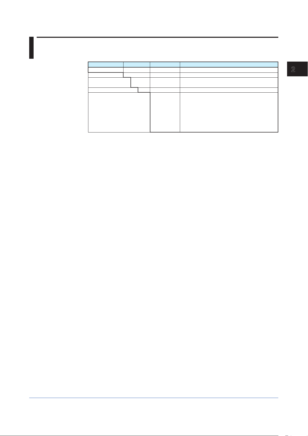
Manual Title Manual No. Description
Rack-Mounted Instruments IM 1B4F2-01E Describes mounting and wiring for the YS80 rack-mounted instruments.
Model VJ77 PC-based
Parameters Setting Tool
Model JHT200 Handy Terminal IM 77J50H01-01EN Describes operation of JHT200.
IM 77J01J77-01E Describes operation for the VJ77 parameters setting tool..
1
1
Introduction
IM 01B04N01-02E
1-1
Page 6
1.1 Inspection
The SISD isolator is shipped only after stringent inspection at the factory. Visually inspect
the product upon delivery to make sure it is not damaged in any way.
Store the box and inner packing material of the package in a safe place - they may be
needed if there is a problem with the product and it needs to be sent back for repair.
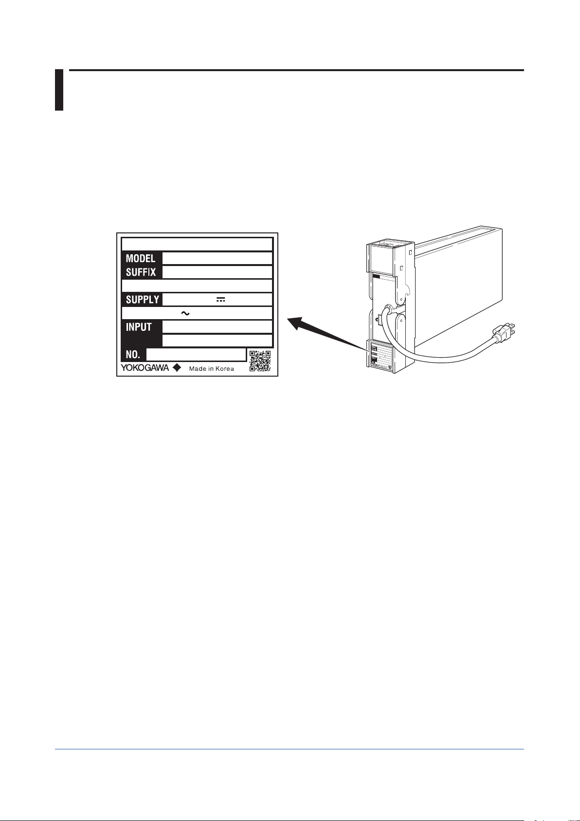
Check of Model and Suffix Codes
The model and suffix codes are indicated on the Name plate attached to the front cover of
the instrument. Crosscheck this information with the model and suffix codes of Section 2.2
to ensure that the product is as specified in the order.
ISOLATOR
SISD
-100*S
24-110VDC
100-120VAC 50/60Hz
100mA
7.0VA
1-5VDC
ISOLATOR
SISD
-100*S
24-110VDC
100-120VAC 50/60Hz
XXXXXXXXX
Figure 1-1 Name plate for Thermocouple Input (Description example)
100mA
1-5VDC
7.0VA
XXXXXXXXX
Confirmation of the Package Contents
Check the package contents against the list below. If anything is missing or damaged,
immediately contact the sales office from which you purchased the product or your nearest
Yokogawa representative.
• SISD Isolator .....................................................................................................1
• Precautions on the Use of the YS80 Series ......................................................1
Downloadable Electronic Manuals
You can download the latest manuals from the following website:
To view the User’s Manuals, use Adobe Acrobat Reader of Adobe Systems Incorporated.
http://www.yokogawa.com/ns/ys/
F0101.ai
1-2
IM 01B04N01-02E
Page 7
1.2 Documentation Conventions
This manual uses the following notational conventions.
Symbols
The following symbols are used in this manual.
Markings
Indicates that operating the hardware or software in a particular
manner may damage it or result in a system failure.
Draws attention to information that is essential for understanding the
operation and/or features of the product.
1
1
Introduction
Description of Displays
Some of the representations of product displays shown in this manual may be exaggerated,
simplified, or partially omitted for reasons of convenience when explaining them.
QR Code
The product has a QR Code pasted for efficient plant maintenance work and asset
information management. It enables confirming the specifications of purchased products and
user’s manuals.
For more details, please refer to the following URL.
https://www.yokogawa.com/qr-code
QR Code is a registered trademark of DENSO WAVE INCORPORATED.
Note
Gives additional information to complement the present topic and/or
describe terms specific to this document.
Gives reference locations for further information on the topic.
IM 01B04N01-02E
1-3
Page 8
1.3 Notice
This Instruction Manual
• This manual should be passed on to the end user. Keep at least one extra copy of the
manual in a safe place.
• Read this manual carefully to gain a thorough understanding of how to operate this
product before you start using it.
• This manual is intended to describe the functions of this product. Yokogawa Electric
Corporation (hereinafter simply referred to as Yokogawa) does not guarantee that these
functions are suited to the particular purpose of the user.
• Under absolutely no circumstances may the contents of this manual, in part or in whole,
be transcribed or copied without permission.
• The contents of this manual are subject to change without prior notice.
• Every effort has been made to ensure accuracy in the preparation of this manual. Should
any errors or omissions come to your attention however, please contact your nearest
Yokogawa representative or sales office.
Protection, Safety, and Prohibition against Unauthorized Modification
• The following safety symbols are used on the product and in this manual.
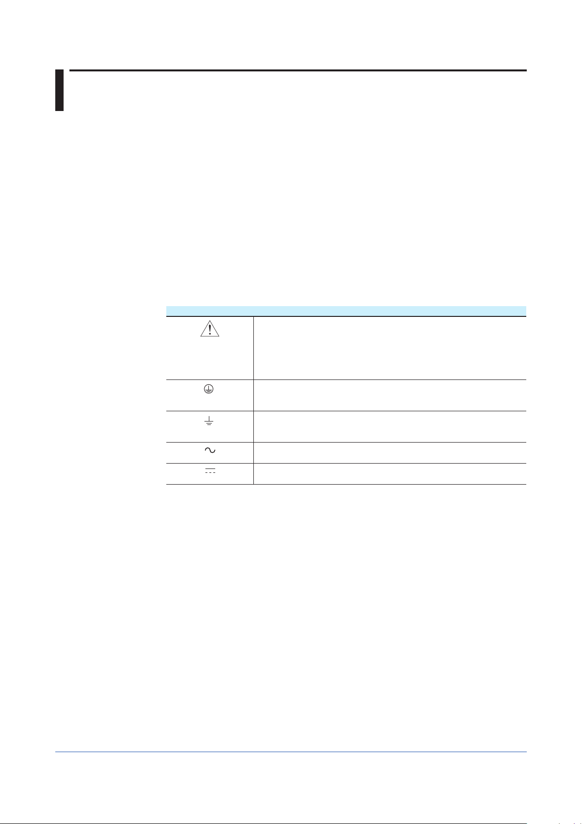
Markings
If this symbol is indicated on the product, the operator should refer
to the explanation given in the instruction manual in order to avoid
personal injury or death to either themselves or other personnel, and/
or damage to the instrument. The manual describes that the operator
should exercise special care to avoid shock or other dangers that may
result in injury or loss of life.
Protective ground terminal:
This symbol indicates that the terminal must be connected to ground
prior to operating the equipment.
Function ground terminal:
This symbol indicates that the terminal must be connected to ground
prior to operating the equipment.
AC voltage:
This symbol indicates that AC voltage is present.
DC voltage:
This symbol indicates that DC voltage is present.
• In order to protect the product and the system controlled by it against damage and ensure
its safe use, make certain that all of the instructions and precautions relating to safety
contained in this document are strictly adhered to. Yokogawa does not guarantee safety
if products are not handled according to these instructions.
• If protection/safety circuits are to be used for the product or the system controlled by it,
they should be externally installed on the product.
• Do not turn off the power of the product during adjustment and parameter setting.
• Be sure to confirm the parameters referring to ‘‘5.4 Parameter List’’ before installing the
product in a system or plant. After confirming them, install the product in a system or plant
and turn on the power.
• When you replace the parts or consumables of the product, only use those specified by
Yokogawa.
• If the product is to be used in systems with special requirements for human safety, such
in as nuclear power and radiation related equipment, railway facilities, aircraft facilities,
and medical devices, please consult with your sales representative.
• Do not modify the product.
Force Majeure
1-4
• Yokogawa does not make any warranties regarding the product except those mentioned
in the WARRANTY that is provided separately.
• Yokogawa assumes no liability to any party for any loss or damage, direct or indirect,
caused by the use or any unpredictable defect of the product.
IM 01B04N01-02E
Page 9
121
Chapter 2 General
General
The SISD isolator receives 1 to 5 V DC input signals and outputs 1 to 5 V DC and 4 to 20
mA DC signals which are isolated from the input signal and the power supply.
With the VJ77 Parameter Setting Tool you can do the following:
• Read/write all parameters at once
• Save read parameters to a file
• Copy parameters to other devices of the same model and suffix code (only with style
code R or S).
2
General
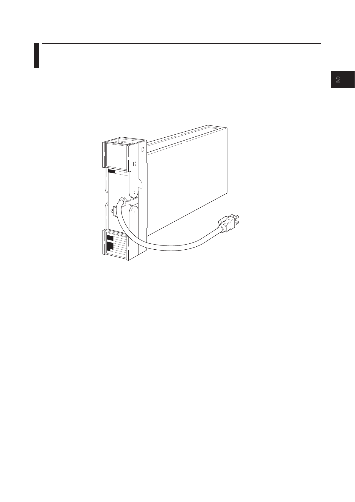
Figure 2-1 External View
F0201.ai
IM 01B04N01-02E
2-1
Page 10

2.1 Standard Specifications
Please see the General Specifications (GS 01B04N01-02E) at the end of this manual.
2-2
IM 01B04N01-02E
Page 11
121
2.2 Model and Suffix Codes
Model Suffix Codes Option Codes Description
SISD Isolator
Number of Input -1 1 input
Square Root Function 00
Style Code *S Style S
Option Codes
*1: /LOCK, /REK, /TB, /A2TB, and /A2ER cannot be specified together.
*2: /FBP, /A2TB, and /A2ER cannot be specified together.
(*1) (*2)
01
/NHR
/FBP
/LOCK
/WSW
/REK
/TB
/A2TB
/A2ER
Not provided
Provided
Without rack case
Power supply fuse bypass
Power supply plug with lock
With spring washer
Mount to same line with EK series rack
With power supply terminal
220V version with power supply terminal
220V version with power supply plug
2
General
IM 01B04N01-02E
2-3
Page 12

Blank
Page 13

1
2
1
2
Chapter 3 Installation
Installation
For details of the installation procedure and wiring precautions, refer to the instruction
manual “Installation of Rack-Mounted Instruments” (IM 1B4F2-01E).
3
3
Installation
IM 01B04N01-02E
3-1
Page 14

3.1 External Wiring
(a) To prepare cables for connection to each terminal, install crimp-on solderless lugs for
4 mm screw on the end of each cable.
(b) Draw the internal unit out from the rack case.
(c) Connect the cables to the correct terminals referring to Table 3-1.
(d) Replace the internal unit into the rack case after completing the wiring.
(e) Always replace the terminal cover after completing the wiring.
The terminal cover cannot be replaced if the internal unit is not installed in the rack
case. The terminal cover should be securely replaced because it has the function of
locking the internal unit.
Terminal arrangement
OUT
K
J
HFDCB
A
3
5
1
2
4
6
8
7
IN
Figure 3-1 Terminal Layout
Applicable Cables
(1) Signal circuit wiring
• Cross-sectional area of the cable conductor: 0.5 to 0.75 mm
• Examples of applicable cables: Single core PVC insulated flexible cable (VSF)
(2) Power supply wiring
• Cross-sectional area of the cable conductor: 1.25 to 2.00 mm
• Examples of applicable cables: 600 V PVC insulated cable (1 V) stranded wires (JIS
Table 3-1 Terminal Wiring
Terminal
Designation
A +
B C
D
F +
H J
K
Do not connect to the output terminal when the terminal is not in use.
Terminal
Designation
1 +
2 3
4
5
6
7
8
Output1 (1 to 5 V DC)
Output2 (4 to 20 mA DC)
Input (1 to 5 V DC)
Description
Description
2
stranded wires (JIS C 3306); heat-resistant vinylinsulated cable (UL style 1007)
2
C 3307);PVC insulated cable for electrical apparatus
(KIV) stranded wires (JIS C 3316)
3-2
IM 01B04N01-02E
Page 15
1
2
3
App
1
2
3
Chapter 4 Principles of Operation
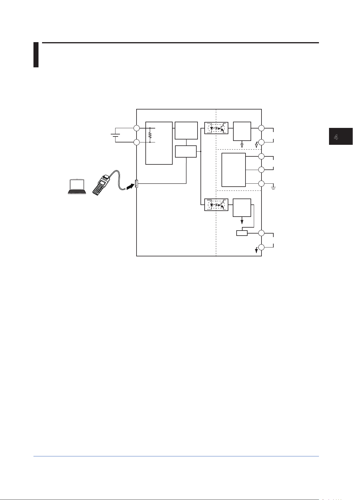
4.1 Principle of Operation
Input signal Ein passes through high-input resistor Rin (1 MΩ, 0 V input at input burnout),
and is converted into digital data in A/D conversion circuit. The digital data has signal
processing (square root characteristic etc.) in micro-processor to be Pulse Width Modulation
(PWM), then is converted into 1 to 5 V DC or 4 to 20 mA DC signals in output circuit through
optical-isolation circuit.
Input (Ein)
PC
(VJ77)
Figure 4-1 Functional Block Diagram
Handy
Terminal
+
1
–
Rin
2
Input
Processing
Circuit
Conversion
processor
A/D
Circuit
Micro-
Isolation Circuit
Isolation Circuit
Power
Supply
Circuit
Output
Circuit
Output
Circuit
V/I
+
A
Output 1 (1 to 5 V DC)
–
B
L+
Supply
N–
GND
+
F
Output 2 (4 to 20 mA DC)
–
H
F0401.ai
4
Principles of Operation
IM 01B04N01-02E
4-1
Page 16

Blank
Page 17

1
2
3
App
1
2
3
4
Chapter 5 Setting
Setting
Items to Confirm before Start of Operation
Before you start operation, inspect and confirm the following items:
(1) Draw out the internal unit from the rack case, and make sure that the specified fuses are
properly mounted in the fuse holders at the rear of the internal unit.
(2) When inserting the internal unit into the rack case, firmly connect the multi-pin connectors
for connecting the internal unit and the case.
(3) Make sure that power plugs are properly connected to the power outlet.
(4) Make sure that external wiring to the terminal block is properly connected.
The SISD isolator is made for operation by simply turning on the power once the installation
and wiring are completed. The isolator does not require parameter settings and the like if
there is no change in the specifications at order.
5
Setting
IM 01B04N01-02E
5-1
Page 18
5.1 Names of Components
Tag plate
BRAIN connector
(w / cover)
Name plate
Output terminal block
Main board
Rack case
Input terminal block
Multi-pin connector
Two-pole plug with earthing contact
Figure 5-1 Names of Component
Terminal cover and handle for
drawing out the internal unit
F0501.ai
5-2
IM 01B04N01-02E
Page 19

1
2
3
App
1
2
3
4
5.2 Setting Jumper
This instrument has the following setting jumpe:
• Parameter Write Protect (JP2): ON/OFF
5.2.1 Check of Setting Jumper and Its Position
Setting jumper is on the main board of the internal unit.
Check the setting jumper in the following procedure.
(a) Pull forward the terminal cover, and draw the internal unit out from the rack case.
(b) Check that the jumper on the main board of the internal unit is set to obtain the desired
action.
(c) Use the tweezers to change the position of jumper.
(d) Put the internal unit back into the rack case.
(e) Replace the terminal cover.
Position and function of setting jumper
Parameter
write protect
(W.P.)
ON
Setting jumper (factory-set default)
5
Setting
OFF
ON:
Parameter change
by a PC (VJ77) or
the Handy Terminal
is prohibited.
Figure5-2. Function and Set Point of Jumper
JP2
F0502.ai
IM 01B04N01-02E
Operation is not guaranteed if the jumper is not set.
5-3
Page 20
5.3 Setting of Parameters
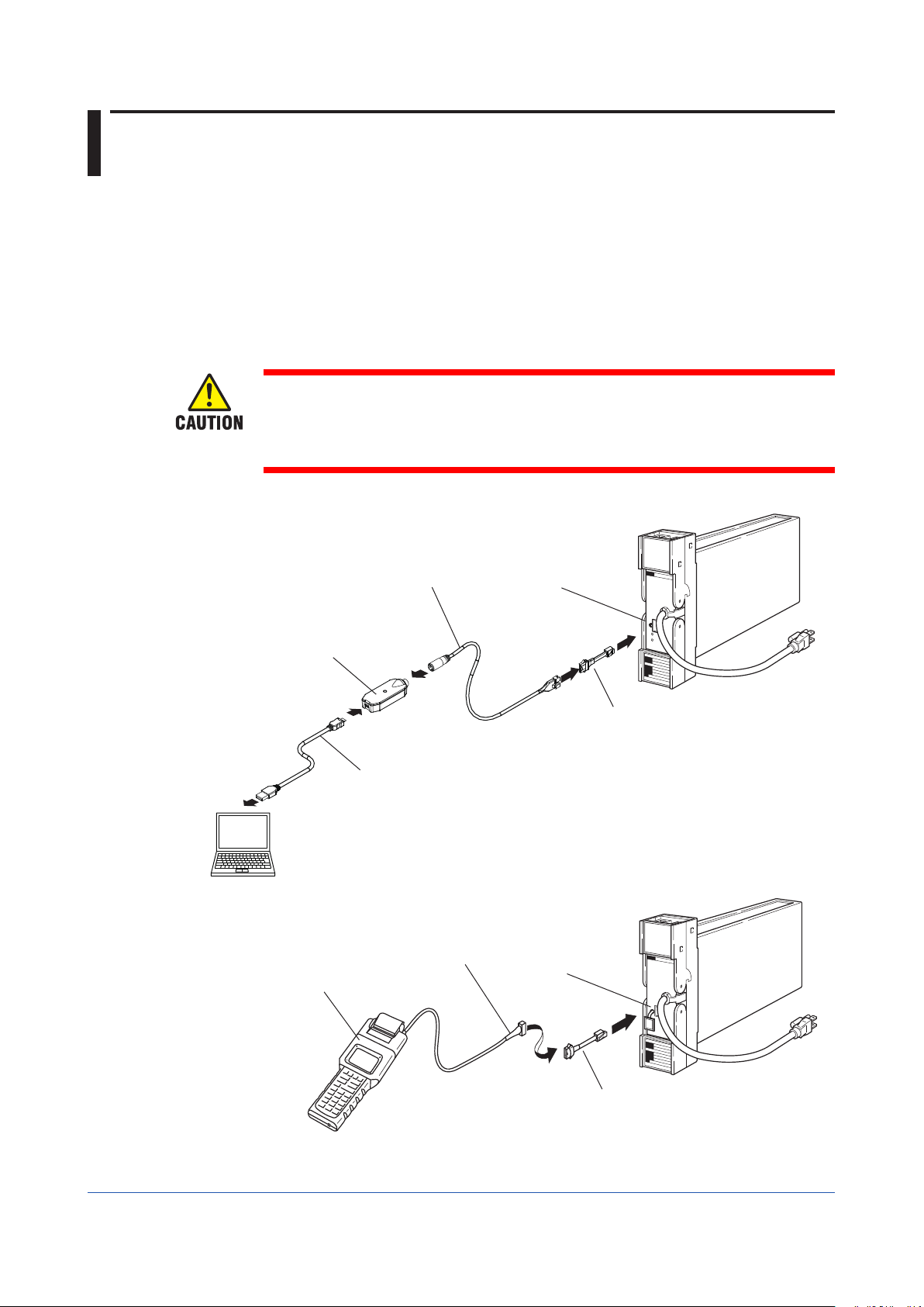
This instrument has BRAIN communication parameters for specifying functions and
adjusting input. Connect a PC (VJ77) or the JHT200 Handy Terminal (Note1) to the
instrument to dis-play or set parameters.
Note 1: BT200 BRAIN Terminal of Yokogawa Electric Corporation can also be used.
When connecting a PC (VJ77) or the JHT200 Handy Terminal, the adapter for
modular-jack (model E9786WH) is required. When using the BT200 BRAIN
Terminal of YOKOGAWA Electric Corporation, the communication cable of
5-pin connector type (model F9182EE) and the adapter for modularjack (model
E9786WH) are required.
• For details of operation and adjusting procedures of VJ77 Parameters Setting Tool,
refer to the instruction manual “Model VJ77 PC-based Parameters Setting Tool” (IM
77J01J77-01E).
• For details of operation and adjusting procedures of JHT200 Handy Terminal, refer
to the instruction manual “JHT200 Handy Terminal” (IM 77J50H01-01EN).
<Connection>
JUXTA communication cable
Dedicated adapter
for VJ77 (L4506HA)
PC
JHT200
Handy Terminal
MicroUSB (USB2.0) cable
JUXTA communication cable
BRAIN connector
Modular-jack
conversion adapter
BRAIN connector
Figure 5-3 Connection
5-4
Adapter for modular jack
(E9786WH)
F0503.ai
IM 01B04N01-02E
Page 21
1
2
3
App
1
2
3
4
5.3.1 Configuration of Parameters
BRAIN communication parameters consist of the following parameters.
• Display (A & B parameters)
• Settings of Input and output (D parameters)
• Adjustment (P parameters)
• Test (Q parameters)
5.3.2 Description of Parameters
The description of main parameters is as follows.
● Input/output-related parameters
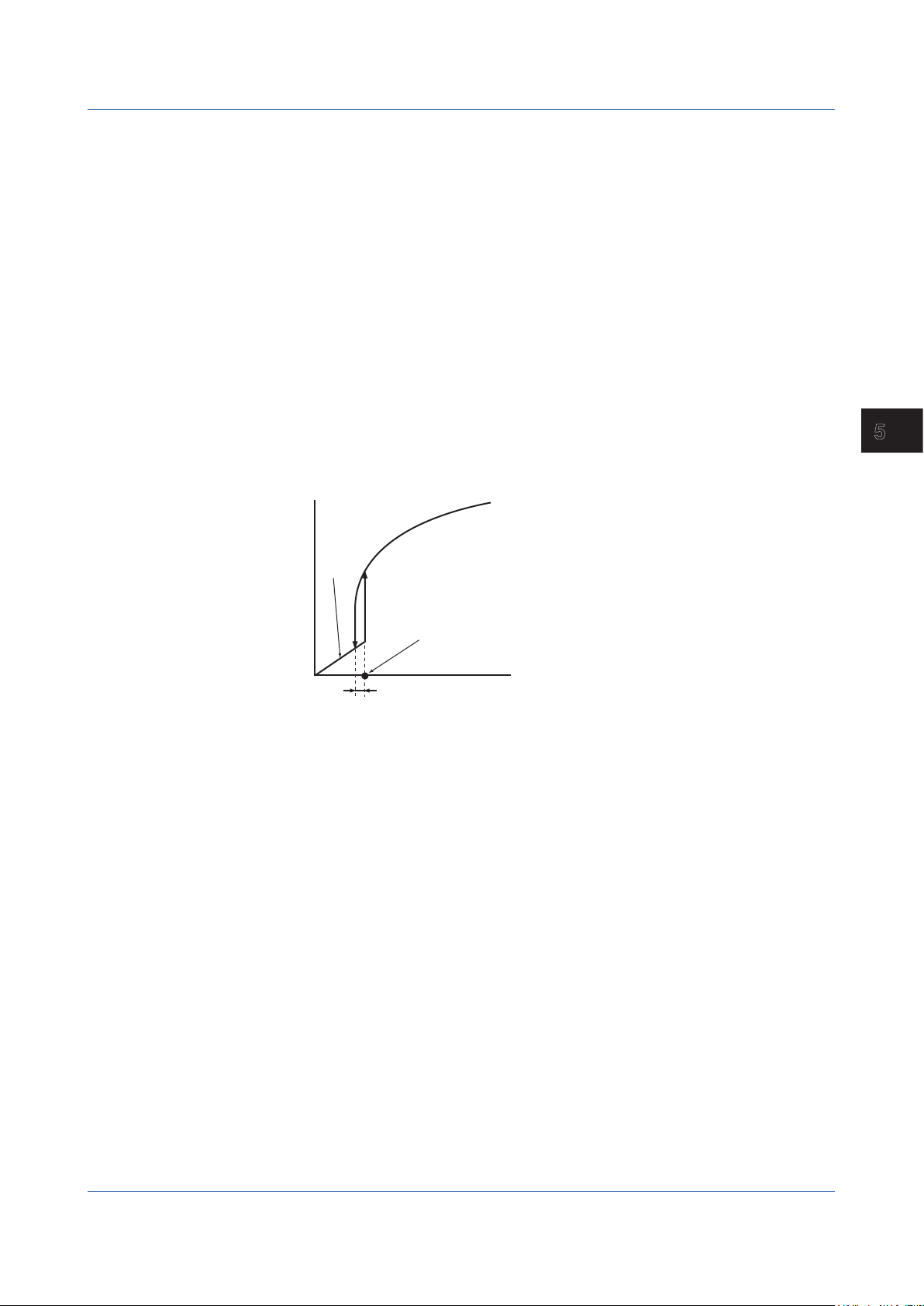
(1) D17: LINEARIZE1
Sets the available/unavailable of square-root characteristic.
(2) D19: LOW CUT1
Sets the low cut point.
The input signal and output signal are shown in the figure below.
If there are square roots, perform square root calculation. You can set a low cut
point (LOW CUT1) for square root calculations. The operation in the vicinity of the
low cut point is shown in the figure below.
A 0.2% hysteresis is used for the low cut point.
Output Signal (Y)
5.3 Setting of Parameters
5
Setting
Y = X
Low cut point
0
Hysteresis (fixed to 0.2%)
(3) D33: OUT1 DR and D34: OUT2 DR
Sets the action direction for output 1 and output 2.
If you set REVERSE, outputs 5 V (or 20 mA) for 0% and 1 V (or 4 mA) for 100%.
● Adjustment-related parameters
(1) P03: ZERO ADJ1
Performs Zero adjustment of input.
(2) P04: SPAN ADJ1
Performs Span adjustment of input.
(3) P13: OUT1 0% (Note1)
Adjusts 0% of output 1.
(4) P14: OUT1 100% (Note1)
Adjusts 100% of output 1.
(5) P15: OUT2 0% (Note1)
(6) P16: OUT2 100% (Note1)
Adjusts 0% of output 2.
Adjusts 100% of output 2.
Input Signal (X)
IM 01B04N01-02E
● Test-related parameters
(1) Q02: OUT1 TEST (Note1)
Outputs the set value forcibly regardless of input condition.
Q03 has the same function.
Note1: After completing adjustment and test, press the [F4] (OK) key of the Handy Terminal
to return to normal condition (release of forced output).
5-5
Page 22

5.4 Parameter List
BRAIN communication parameters for SISD are as follows.
No. Symbol Parameter Name Setting Range Unit Factory-set Value Setting Type
01 MODEL Model Name –––– Display
02 TAG NO Tag Number –––– Display
03 SELF CHK Self Check GOOD/ERROR –––– Display
<Display Parameters>
A DISPLAY1 Menu Name
A01 INPUT1 Input Display V Display
A09 OUTPUT1 Output1 Display % Display
A10 OUTPUT2 Output2 Display % Display
A54 STATUS Status Display (Note1) 0000 to FFFF –––– Display
A55 WRT PROTECT Parameter Write Protect ON/OFF –––– OFF Display
A56 REV NO. Revision number –––– Display
A58 MENU REV Menu Revision number –––– Display
A60 SELF CHK Self Check GOOD/ERROR –––– Display
B DISPLAY2 Menu Name
B01 INPUT1 Input Display V Display
B09 OUTPUT1 Output1 Display % Display
B10 OUTPUT2 Output2 Display % Display
B60 SELF CHK Self Check GOOD/ERROR –––– Display
<Setting Parameters>
D SET(I/O) Menu Name
D01 TAG NO.1 Tag Number1 Up to 8-single-byte –––– Alphanumeric
D02 TAG NO.2 Tag Number2 Up to 8-single-byte –––– Alphanumeric
D03 COMMENT1 Comment1 Up to 8-single-byte –––– Alphanumeric
D04 COMMENT2 Comment2 Up to 8-single-byte –––– Alphanumeric
D17 LINEARIZE1 Linearize OFF/SQR –––– OFF
D19 LOW CUT1 Low Cut 0.3 to 100.0 % 1.0 Real Number
D33 OUT1 DR Output1 Direction DIRECT/REVERSE –––– DIRECT Selection
D34 OUT2 DR Output2 Direction DIRECT/REVERSE –––– DIRECT Selection
D60 SELF CHK Self Check GOOD/ERROR –––– Display
<Adjustment Parameters>
P ADJUST Menu Name
P03 ZERO ADJ1 Zero Adjustment Note2 Selection
P04 SPAN ADJ1 Span Adjustment Note2 Selection
P13 OUT1 0% Output1 0% -20.00 to 20.00 % 0.00 Real Number
P14 OUT1 100% Output1 100% -20.00 to 20.00 % 0.00 Real Number
P15 OUT2 0% Output2 0% -20.00 to 20.00 % 0.00 Real Number
P16 OUT2 100% Output2 100% -20.00 to 20.00 % 0.00 Real Number
P60 SELF CHK Self Check GOOD/ERROR –––– Display
<Test Parameters>
Q TEST Menu Name
Q02 OUT1 TEST Output1 Test -25.0 to 125.0 % 0.0 Real Number
Q03 OUT2 TEST Output2 Test -25.0 to 125.0 % 0.0 Real Number
Q60 SELF CHK Self Check GOOD/ERROR –––– Display
Note 1: The condition of the instrument is displayed.
Note 2: V RST/V INC/V HINC/V HDEC/V DEC
SQR for SISD-101
Selection
5-6
IM 01B04N01-02E
Page 23

1
2
3
App
1
2
3
5
4
Chapter 6 Maintenance
Maintenance
This chapter describes the calibration procedures that can be done in the instrument room
or service shop.
6
Maintenance
IM 01B04N01-02E
6-1
Page 24

6.1 Test Equipment
For efficient maintenance of this isolator, it is recommended that the user have the following
test equipment manufactured by Yokogawa or their equivalent.
● DC Voltage/Current Standard, Yokogawa GS200 or the equivalent…...…….. 1 set
● Digital Voltmeter, Yokogawa DM7560 or the equivalent.................................. 1 set
● PC, VJ77 Parameters Setting Tool.................................................................. 1 set
● Handy Terminal, JHT200 (BT200)................................................................... 1 set
● Modular jack conversion adapter, Part No. E9786WH.................................... 1 set
6-2
IM 01B04N01-02E
Page 25

1
2
3
App
1
2
3
5
4
6.2 Adjustment
• For details of operation and adjusting procedures of VJ77 Parameters Setting Tool,
refer to the instruction manual “Model VJ77 PC-based Parameters Setting Tool” (IM
77J01J77-01E).
• For details of operation and adjusting procedures of JHT200 Handy Terminal, refer
to the instruction manual ‘‘JHT200 Handy Terminal’’ (IM 77J50H01-01EN).
• Donotturnothepoweroftheinstrumentduringadjustment.
Use a PC (VJ77) or the JHT200 Handy Terminal for adjustment.
The procedure is shown below using the JHT200 Handy Terminal as an example.
Adjust SISD using JHT200 Handy Terminal.
(a) Connect the equipment as illustrated in Figure 6-1.
(b) Set the Parameter Write Protect (W.P.) of setting jumper to OFF. (Refer to ‘‘5.2 Setting
Jumper’’.)
(c) Turn on the power, and allow the equipment to warm up for about 5 minutes under this
condition.
(d) Connect JHT200 Handy Terminal.
<Connection>
6
Maintenance
JUXTA communication cable
Dedicated adapter
for VJ77 (L4506HA)
MicroUSB (USB2.0) cable
PC
JUXTA communication cable
JHT200
Handy Terminal
BRAIN connector
Modular-jack
conversion adapter
BRAIN connector
Figure 6-1 Connection
IM 01B04N01-02E
Adapter for modular jack
(E9786WH)
F0601.ai
6-3
Page 26

6.2 Adjustment
(e) Call the adjustment item (P: ADJUST).
(f) P03: ZERO ADJ1 is displayed.
(g) Apply an input equivalent to 0% of the input range. Check the input value and the input
display of P03: ZERO ADJ1. If the input value does not correspond to the display value,
select P03: ZERO ADJ1 to enter the adjustment mode. Mainly select INC (addition) or
DEC (subtraction) for adjustment. (Selecting RST resets the adjusted value and retrieves the factory-set default.) Selecting HINC or HDEC performs adjustment using a
value ten times as large as INC or DEC.
(h) Apply an input equivalent to 100% of the input range. Check the input value and the
in- put display of P04: SPAN ADJ1. If the input value does not correspond to the display
value, select P04: SPAN ADJ1 to enter the adjustment mode. Mainly select INC (addition) or DEC (subtraction) for adjustment. (Selecting RST resets the adjusted value and
retrieves the factory-set default.) Selecting HINC or HDEC performs adjustment using a
value ten times as large as INC or DEC.
(i) After completing the adjustment, set the parameter write protect (W.P.) of setting jumper
to ON. (Refer to ‘‘5.2 Setting Jumper’’.)
Yokogawa DM7560 or the equivalent
Digital Voltmeter
Digital Voltmeter
Note: The broken line shows
4 to 20 mA DC output
test circuit.
Yokogawa GS200 or the equivalent
DC Voltage/Current
Standard
Figure 6-2 Adjustment
250 0.05 %
–
+
+
–
+
–
J K
DB H
FCA
531
2 4 6
87
Power supply
F0602.ai
6-4
IM 01B04N01-02E
Page 27

1
2
3
App
1
2
3
5
4
6.3 List of Replaceble Parts
Contact YOKOGAWA’s sales office or sales representative when replacing the spare
parts.
Part Name Part Number Recommended
Fuse S9510VK Approx. 3 years If the fuse breaks or if the
Power supply
unit
L3510YA: Standard
L3510YF:
L3510YT: Option code /A2TB
L3510YR: Option code /A2ER
Option codes /TB,
/FBP, or /REK
replacement period
replacement period elapses,
please have the item replaced.
5-10 years As the aluminum electrolytic
capacitors used in the power
supply unit are subject to
deterioration from temperature
and other operating conditions,
we recommend the replacement
period on the left.
Reference
6
Maintenance
IM 01B04N01-02E
6-5
Page 28

Blank
Page 29

1
2
3
App
1
2
3
5
6
4
Chapter 7 Troubleshooting
Troubleshooting
If any fault occurs in the instrument, note the symptoms and follow Section 7.1.
7
Troubleshooting
IM 01B04N01-02E
7-1
Page 30

7.1 Action in Fault Condition
The output condition and error codes (BRAIN communication parameters) in fault condition
are shown in the table below.
• STATUS is displayed in A54 of A: DISPLAY (display), and SELF CHK is displayed in
60 of each item.
• STATUS error code is to be the addition display (hexadecimal number) when two
errors or more occur.
BRAIN Communication Parameter
aDisplay
STATUS SELF CHK Error Information
(*1)
0001 ERROR EEPROM ERROR Output: 0% or less
0002 ERROR EEPROM SUM
ERROR
1000 ERROR AD ERROR Output: 0% or less
0008 ERROR INPUT OVER
RANGE
0004 GOOD LOW_CUT Output: Normal action
0040 GOOD None Output: Normal action
0000 GOOD None Output: Normal action
*1: Displayed when calling 60: SELF CHK.
*2: If errors continue even when the input is within the range, the input circuit is broken.
Contact YOKOGAWA's sales office or sales representative.
Output Condition Description of Error Remedy
Same state as power off
Output: 0% or less
Communication: Stopped
Communication: Undefined
Output: 0% or less
Communication: Undefined
Communication: Normal action
Output: Normal action
Communication: Normal action
Communication: Normal action
Communication: Normal action
Communication: Normal action
Hardware failure Contact YOKOGAWA's sales
Power failure, Fuse
broken
EEPROM error
Parameter error
A/D conversion error
Excessive input, out of
-25 to 125%
Input below the square
root characteristic with
low-cut
Check power failure
during operation
- -
office or sales representative.
Set the input within the range.
(*2)
Apply the input greater than
the low-cut point.
Write "0000" at the
STATUS display of BRAIN
communication parameter
7-2
IM 01B04N01-02E
Page 31

1
2
3
App
1
2
3
5
6
7
4
Chapter 8 Power Supply Terminal Connections (Options /TB, /A2TB, and /REK)
Power Supply Terminal Connections (Options /TB,
/A2TB, and /REK)
If you specify the terminal block to which the power source is directly connected (option
codes: /TB, /A2TB, and /REK), the external wiring to the terminal block is necessary;
therefore, drawing out the internal unit requires previous turning off of the power source and
disconnection of the wiring from the terminal block.
8
Power Supply Terminal Connections (Options /TB, /A2TB, and /REK)
IM 01B04N01-02E
8-1
Page 32
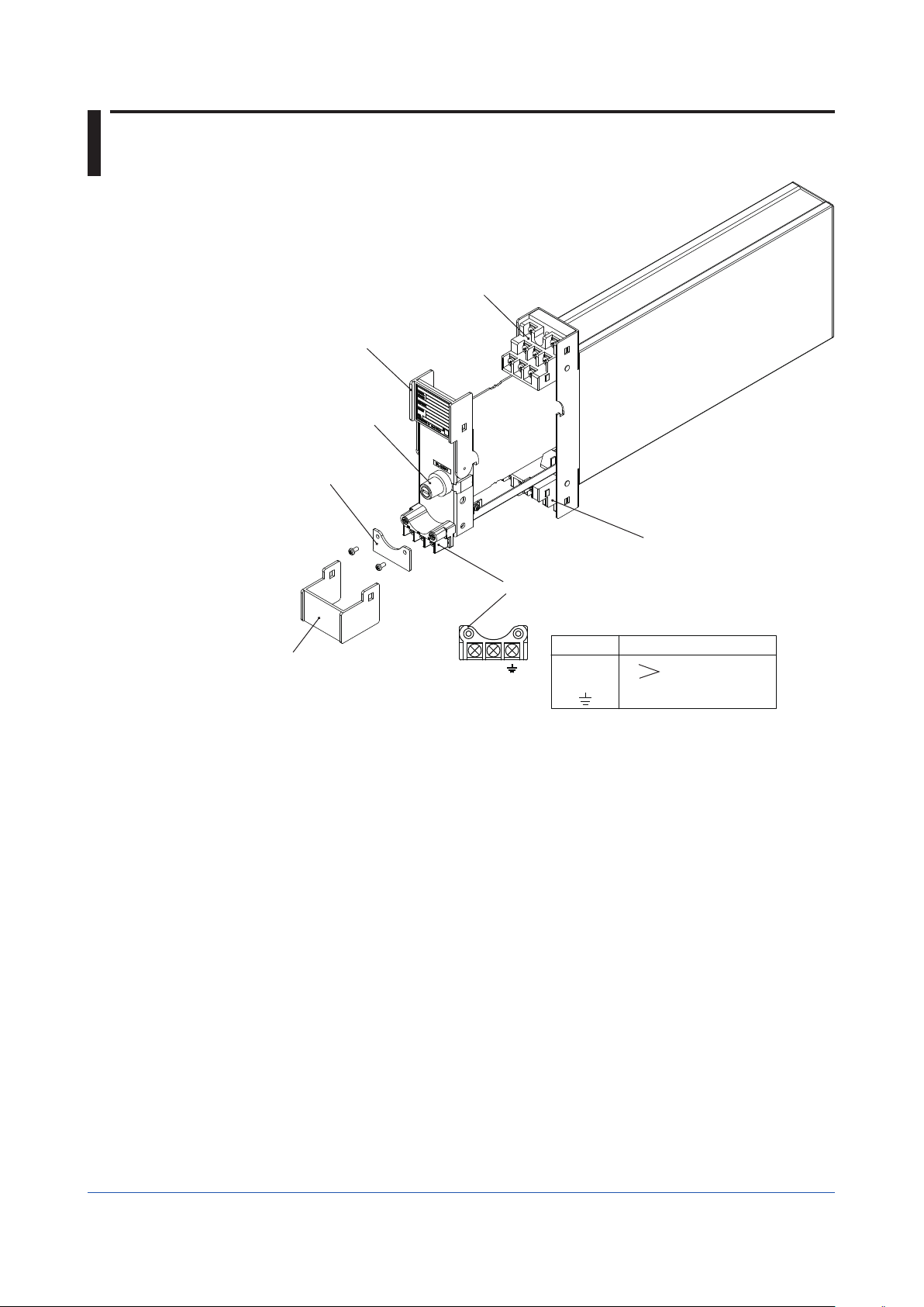
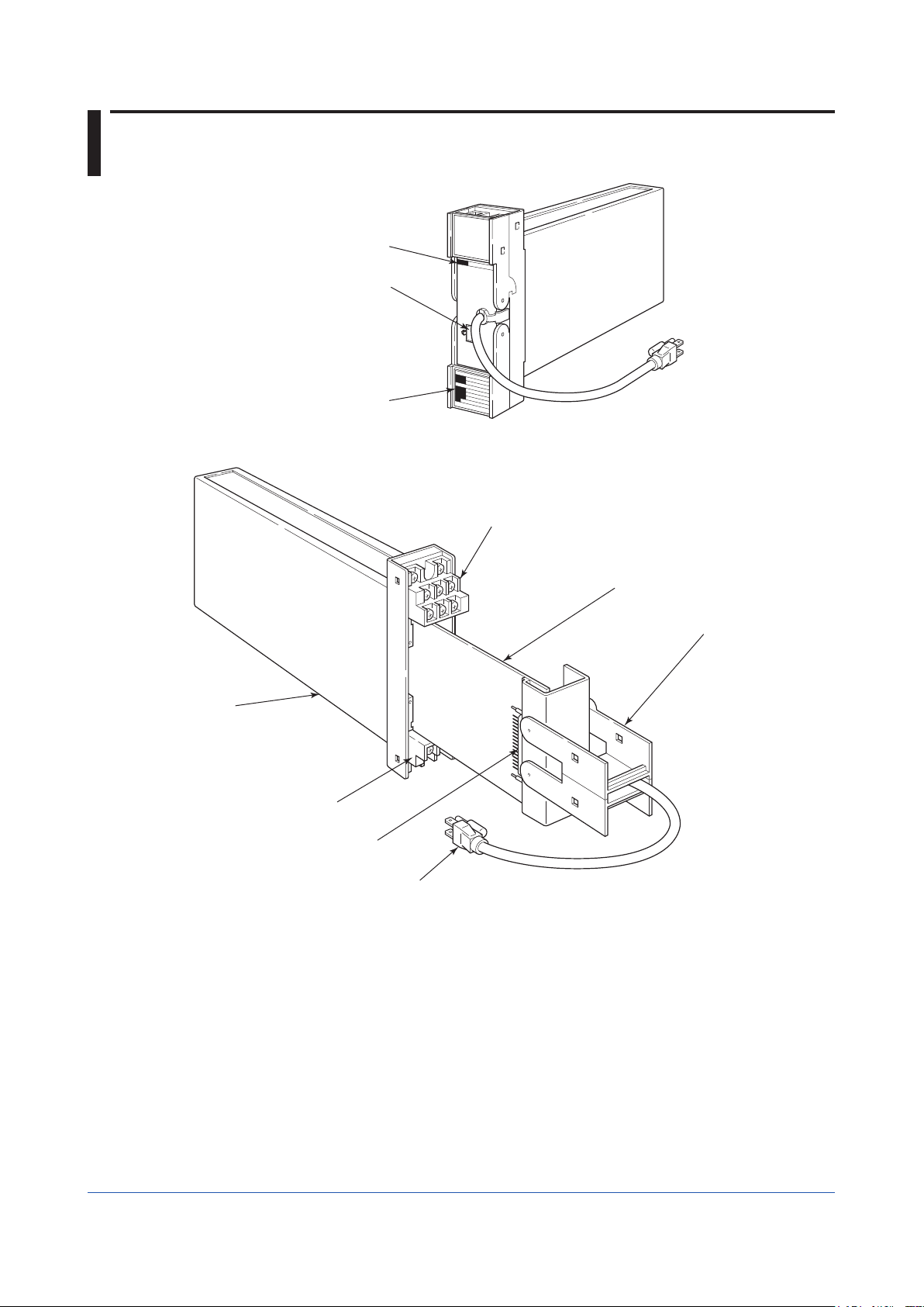
8.1 External View and Names of Components
Output Terminal Block
Output Terminal Cover
Power Fuse
Power Terminal Cover
Input Terminal Block
Power Terminal
Power and Ground Terminal connection
(Connection screw: M4)
Description
+
L
-
N
Ground
Power supply
Input Terminal Cover
Symbol
L N
Figure 8-1 External View and Names of Components
8-2
IM 01B04N01-02E
Page 33

1
2
3
App
1
2
3
5
6
7
4
8.2 Power Supply And Ground Wiring
(1) All cable ends must be furnished with crimp-on type solderless lugs (for 4 mm screw).
(2) Examples of applicable cables:
Cross-sectional area of the cable conductor: 2.0 mm
Applicable cable: 600 V vinyle insulated cable (IV) stranded wires, conforming to JIS
C3307.
Vinyle sheathed cables for electric appliances (KIV) stranded
wires, conforming to JIS C3316.
Note *: Power supply cables should be determined from the instrument power
consumption-they must have conductors with cross-sectional area of at least
1.25 mm
(3) Wirings to power supply and ground terminals should be made after completion of signal
terminal wirings. (To facilitate connecting input signal, pull the internal unit approximately
half way out of the housing. Do not remove the power terminal block.)
(4) After completing the power supply and ground wiring, mount the power terminal cover.
2
.
2
. *
8
Power Supply Terminal Connections (Options /TB, /A2TB, and /REK)
IM 01B04N01-02E
8-3
Page 34

Blank
Page 35
General
Computation: E = 2 E – 1 + 1
E : Output Signal from computation function, E : Input Signal
0
Specications
Model SISD (Style S)
Isolator
GS 01B04N01-02E
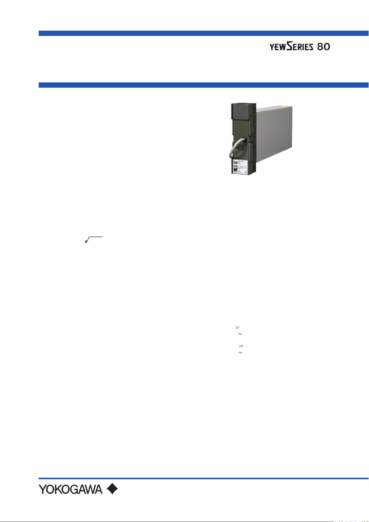
n GENERAL
The Model SISD Isolator accepts a 1 to 5V DC input
signal. The input signal is isolated from the power
supply common and from the Isolator output signal.
There are two outputs: 1 to 5V and 4 to 20mA DC.
With the VJ77 Parameter Setting Tool you can do the
following:
· Read/write all parameters at once
·Savereadparameterstoale
· Copy parameters to other devices of the same model
andsuxcode(onlywithstylecodeRorS).
n STANDARD SPECIFICATIONS
Input Signal
Input: 1 to 5V DC(one input)
Input Resistance: 1 MΩ
Square Root Characteristic
0
1
Lowcut Function: At E1 is less than 1% , the output is
proportional to input.
Output Signals
Output: 1 to 5V DC(one output), 4 to 20 mA
Load Resistance: At least 2 kΩ(1 to 5 V DC output),
DC(one output)
up to 750 Ω (4 to 20 mA DC output)
BRAIN Communication Function
Setting of each parameter, monitoring of input/output
values, and conguration by a PC (VJ77), JHT200
Handy Terminal* or BT200 BRAIN Terminal*.
*: When connecting a PC (VJ77) or the JHT200
Handy Terminal, the adapter for modular-jack
(model E9786WH) is required. When using the
BT200 BRAIN Terminal of YOKOGAWA Electric
Corporation, the communication cable of 5-pin
connector type (model F9182EE) and the adapter
for modular-jack (model E9786WH) are required.
n MOUNTING AND APPEARANCE
Mounting: Rack mounting.
Wiring
Signal Wiring: ISO M4 size (4mm) screws on
Power and Ground Wiring
100 V version: JIS C 8303 two-pin plug with
Cable length: 300 mm
Power supply terminal type (option
220 V version: CEE 7 VII(CENELEC standard)
terminal block.
earthing contact(IEC A5-15, UL458)
code /TB)
plug (option code /A2ER).
Cable length: 300 mm
Power supply terminal type (option
External Dimensions: 180 (H)× 48(W)× 300 (D)
Weight: 1.7 kg (including rack-mounting case)
code /A2TB)
Depth behind panel(mm)
n STANDARD PERFORMANCE
Accuracy: ±0.2% of span(±0.5% of span with square
Maximum Power Consumption:
root characteristic)
70 mA with 24 V DC supply,
5.0 VA with 100 V AC supply,
6.0 VA with 220 V AC supply.
n POWER SUPPLY AND ISOLATION
Power Supply Rated Voltage:
100 V version:
24-110 VDC
100-120 VAC
220 V version:
135-300 VDC
200-240 VAC
Power Supply Input Voltage: AC/DC both usage
100 V version: DC drive 20 to 130 V, no polarity
AC drive 80 to 138 V, 47 to 63 Hz
220 V version: DC drive 120 to 340 V, no polarity
AC drive 138 to 264 V, 47 to 63 Hz
Insulation Resistance
Between I/O terminals and Ground:
100 MΩ/500 V DC
Between Power and Ground:
100 MΩ/500 V DC.
Dielectric Strength
Between I/O terminals and Ground:
500 V AC for 1 minute.
Between Power and Ground:
1000 V AC for 1 minute(100 V version)
1500 V AC for 1 minute(220 V version)
Between Input terminal and Output terminal:
1000 V AC for 1 minute
, -10 %, +10 %, 100 mA
, -10 %, +10 %, 50/60 Hz, 7.0 VA
, -10 %, +10 %, 15 mA
, -10 %, +10 %, 50/60 Hz, 10.0 VA
GS 01B04N01-02E
©Copyright Jan. 1983 (YK)
13th Edition Jan. 2021 (YK)
Page 36

n NORMAL OPERATING CONDITIONS
Ambient Temperature: 0 to 50 °C
Ambient Humidity: 5 to 90% relative humidity
(non-condensing)
Operating environment: Area free of hydrogen sulde
gas and other corrosive
gases and dust and where
the device is not exposed to
sea breeze or direct sunlight.
Continuous vibration: (at 5 to 9 Hz) Half amplitude of
1.5 mm or less
(at 9 to 150 Hz) 4.9m/s
2
or less,
1 oct/min for 90 minutes each
in the three axis directions
Impact: 49 m/s
2
or less, 11 ms, 3 axes, 6 directions, 3
times each
Installation altitude: 2,000 m or less above sea level
Warm-up time: 15 minutes or more after the power is
turned on
n TRANSPORT AND STORAGE
CONDITIONS
Temperature: -25 to 70°C
Temperature change rate: 20°C per hour or less
Humidity: 5 to 95%RH (no condensation)
2
n OPTIONS
/NHR: Without rack case (internal unit only)
/FBP: Power supply fuse bypass
/LOCK: Power supply plug with lock
/WSW: With spring washer
/REK: Mount to same line with EK series rack
/TB: With power supply terminal
/A2TB: 220V version with power supply terminal
/A2ER: 220V version with power supply plug
n TERMINAL CONNECTIONS
Terminal arrangement
OUT
K
J
HFDCB
A
3
5
1
2
4
6
8
7
IN
Terminal
Designation
A +
B -
C
D
F +
H J
K
Do not connect to the output terminal when the terminal is not in use.
Terminal
Designation
1 +
2 -
3
4
5
6
7
8
Output1 (1 to 5 V DC)
Output2 (4 to 20 mA DC)
Input (1 to 5 V DC)
Description
Description
All Rights Reserved. Copyright © 2001, Yokogawa Electric Corporation
GS 01B04N01-02E
Jan.12, 2021-00
Page 37

n EXTERNAL DIMENSIONS
Power supply plug type
3
180
48
Cable length:300 mm
Trigonometry
Unit: mm
General tolerance = ±(value of tolerance class IT18 based on JIS B 0401-2016) / 2
Power supply terminal type(option /TB or /A2TB)
136
22
30052
F01.ai
52
180
48
Power supply
terminal block
L N
Trigonometry
Unit: mm
General tolerance = ±(value of tolerance class IT18 based on JIS B 0401-2016) / 2
All Rights Reserved. Copyright © 2001, Yokogawa Electric Corporation
71 300
Power and Ground Terminal connection
(Connection screw: M4)
Symbol
Description
+
L
-
N
Power supply
Ground
GS 01B04N01-02E
13622
F02.ai
Jan.12, 2021-00
Page 38

Power supply terminal type(option /REK)
4
200
2-ø7
1905
52
32 136
48
Power supply
terminal block
L N
71 300
Power and Ground Terminal connection
(Connection screw: M4)
Symbol
Description
+
L
-
N
Power supply
Ground
Trigonometry
Unit: mm
General tolerance = ±(value of tolerance class IT18 based on JIS B 0401-2016) / 2
F03.ai
All Rights Reserved. Copyright © 2001, Yokogawa Electric Corporation
GS 01B04N01-02E
Jan.12, 2021-00
Page 39

n MODEL AND SUFFIX CODES
Model Sux Codes Option Codes Descriptions
SISD Isolator
Number of
Input
Square Root
Function
Style Code *S Style S
Option Codes
*1: /LOCK, /REK, /TB, /A2TB, and /A2ER cannot be specied together.
*2: /FBP, /A2TB, and /A2ER cannot be specied together.
-1 1 input
00 Not provided
01 Provided
(*1) (*2)
/NHR
/FBP
/LOCK
/WSW
/REK
/TB
/A2TB
/A2ER
Without rack case
Power supply fuse bypass
Power supply plug with lock
With spring washer
Mount to same line with EK series rack
With power supply terminal
220V version with power supply terminal
220V version with power supply plug
n ORDERING INSTRUCTIONS
Specify the following when ordering:
Model and sux codes and option codes, if necessary.
5
5
All Rights Reserved. Copyright © 2001, Yokogawa Electric Corporation
Subject to change without notice.
GS 01B04N01-02E
Jan.12, 2021-00
Page 40

Page 41

Revision Information
Title : Model SISD (Style S) Isolator
Manual No. : IM 01B04N01-02E
8th Edition/May 2004
Change of the company name.
9th Edition/Oct. 2019
Change of the style number.
10th Edition/Jan. 2021
VJ77 parameter setting tool (R3.01 or later) support
Written by Yokogawa Electric Corporation
Published by Yokogawa Electric Corporation
2-9-32 Nakacho, Musashino-shi, Tokyo 180-8750, JAPAN
i
Page 42

YOKOGAWA ELECTRIC CORPORATION
Headquarters
9-32, Nakacho, 2-chome, Musashino-shi, Tokyo, 180-8750 JAPAN
Phone : 81-422-52-5555
Branch Sales Offices
Osaka, Nagoya, Kurashiki, Hiroshima, Fukuoka, Kitakyusyu
YOKOGAWA CORPORATION OF AMERICA
Head Office
12530 West Airport Blvd, Sugar Land, Texas 77478, USA
Phone : 1-281-340-3800 Fax : 1-281-340-3838
Georgia Office
2 Dart Road, Newnan, Georgia 30265, USA
Phone : 1-800-888-6400 Fax : 1-770-254-0928
YOKOGAWA AMERICA DO SUL LTDA.
Praca Acapulco, 31 - Santo Amaro, Sáo Paulo/SP, BRAZIL, CEP-04675-190
Phone : 55-11-5681-2400 Fax : 55-11-5681-4434
YOKOGAWA EUROPE B. V.
Euroweg 2, 3825 HD Amersfoort, THE NETHERLANDS
Phone : 31-88-4641000 Fax : 31-88-4641111
YOKOGAWA ELECTRIC CIS LTD.
Grokholsky per 13 Building 2, 4th Floor 129090, Moscow, RUSSIA
Phone : 7-495-737-7868 Fax : 7-495-737-7869
YOKOGAWA CHINA CO., LTD.
3F Tower D Cartelo Crocodile Building, No.568 West Tianshan Road,
Shanghai 200335, CHINA
Phone : 86-21-62396262 Fax : 86-21-62387866
YOKOGAWA ELECTRIC KOREA CO., LTD.
(Yokogawa B/D, Yangpyeong-dong 4-Ga), 21, Seonyu-ro 45-gil, Yeongdeungpo-gu,
Seoul, 07209, KOREA
Phone : 82-2-2628-6000 Fax : 82-2-2628-6400
YOKOGAWA ENGINEERING ASIA PTE. LTD.
5 Bedok South Road, Singapore 469270, SINGAPORE
Phone : 65-6241-9933 Fax : 65-6241-2606
YOKOGAWA INDIA LTD.
Plot No.96, Electronic City Complex, Hosur Road, Bangalore - 560 100, INDIA
Phone : 91-80-4158-6000 Fax : 91-80-2852-0625
YOKOGAWA AUSTRALIA PTY. LTD.
Tower A, 112-118 Talavera Road, Macquarie Park NSW 2113, AUSTRALIA
Phone : 61-2-8870-1100 Fax : 61-2-8870-1111
YOKOGAWA MIDDLE EAST & AFRICA B.S.C.(C)
P.O. Box 10070, Manama, Building 577, Road 2516, Busaiteen 225, Muharraq,
BAHRAIN
Phone : 973-17-358100 Fax : 973-17-336100
Oct. '18
 Loading...