

General
Specications
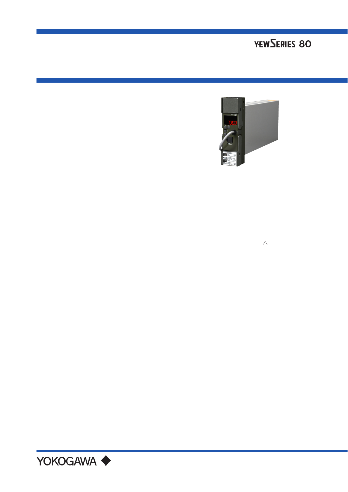
Model SIND (Style S)
Integrator
GS 01B04M01-02E
n GENERAL
The SIND Integrator is a voltage-to-pulse converter
that converts 1 to 5 V DC inputs to corresponding
pulse frequency output. It can be used with a YS80
series SICD counter to totalize ow quantity.
Two integrating modes are available: proportional
integration that directly totalizes the input, and square
root integration that totalizes square-root values.
A PC (VJ77) or the JHT200 Handy Terminal* is used
for setting the Integrator parameters. On the SIND
model with display setter (SIND-04), input indication
can be displayed and integrating ratio and low input
cut o can be displayed / set on the front panel.
With the VJ77 Parameter Setting Tool you can do the
following:
· Read/write all parameters at once
· Save read parameters to a le
· Copy parameters to other devices of the same model
and sux code (only with style code R or S).
*: The BT200 BRAIN Terminal of YOKOGAWA
Electric Corporation can also be connected.
The adapter for modular jack (E9786WH) is
required for connecting a PC (VJ77) or the
JHT200 Handy Terminal to the Integrator.
n STANDARD SPECIFICATIONS
Indication Setting Function (SIND-04):
Digital indicator 5-digit 7-segment LED (1
Indication range: -19999 to +32000 (decimal
At input value indication LED indicator is out.
LED indicators (PPH, LCT: green)
At integrating ratio (PPH) indication: Lit
At low cuto level indication (LCT): Lit
Setter Setting (→, ↑, SET,
Setting enable switch 1
Integrating ratio and low input cuto can
be set.
row)
point selectable)
) switches 4
Input Signals
Input: 1 to 5 V DC
Number of inputs: 1
Input resistance: 1 MΩ
Output signal
Output: Transistor contact or SICD
Number of outputs: 2
Load current:
Transistor contact 30 V DC, 150 mA or less
SICD counter drive pulse 24 V DC, 150 mA or less
Integration mode: Proportional or square root
Integrating ratio range: 1 to 10000 pph
Pulse ON Time: 30 ms and 60 ms*
*2: Number of outputs becomes 1 as two outputs are
shared.
Low input cuto:
In proportional integration mode: Input cuto level
set to 0 to 10% of input signal.
In square-root integration mode: Input cuto level
set to 0.3 to 10% of input signal.
BRAIN Communication Function:
Parameters are set and functions specied by a PC
(VJ77) or the JHT200 Handy Terminal*.
counter drive pulse (24 V DC)
2
n MOUNTING AND APPEARANCE
Mounting: Rack mounting
Wiring
Signal Wiring: ISO M4 size (4 mm) screws on
terminal block
Power and Ground Wiring
100 V version: JIS C 8303 two-pin plug with
earthing contact
Cable length: 300 mm
Power supply terminal type
(option code /TB)
200 V version: CEE 7 VII (CENELEC standard)
plug (option code /A2ER)
Cable length: 300 mm
Power supply terminal type
(option code /A2TB)
External Dimensions (depth behind panel):
180 (H) x 48 (W) x 300 (D) (mm)
Weight: 1.7 kg (including rack-mounting
case)
GS 01B04M01-02E
©Copyright Jan. 1983(YK)
10th Edition Jan. 2021(YK)

2
n STANDARD PERFORMANCE
Accuracy: ±0.5% of span
Maximum Power Consumption
Integrating
ratio
1000 pph 100 mA 7.3 VA 10.2 VA
10000 pph 190 mA 10.8 VA 13.7 VA
24 V DC 100 V AC 220 V AC
Power Supply
n POWER SUPPLY AND ISOLATION
Power Supply Rated Voltage:
100 V version:
24-110 VDC
100-120 VAC
220 V version:
135-300 VDC
200-240 VAC
Power Supply Input Voltage: AC/DC both usage
100 V version: DC drive 20 to 130 V, no polarity
AC drive 80 to 138 V, 47 to 63 Hz
220 V version: DC drive 120 to 340 V, no polarity
AC drive 138 to 264 V, 47 to 63 Hz
Insulation Resistance
Between I/O terminals and Ground: 100 MΩ/500 V
Between Power and Ground: 100 MΩ/500 V DC
Dielectric Strength
Between I/O terminals and Ground:
500 V AC for 1 minute
Between Power and Ground:
1000 V AC for 1 minute (100 V version)
1500 V AC for 1 minute (220 V version)
, -10 %, +10 %, 250 mA
, -10 %, +10 %, 50/60 Hz, 14.0 VA
, -10 %, +10 %, 30 mA
, -10 %, +10 %, 50/60 Hz, 15.0 VA
DC
n OPTIONS
/NHR: Without rack case (internal unit only)
/FBP: Power supply fuse bypass
/LOCK: Power supply plug with lock
/WSW: With spring washer
/REK: Mount to same line with EK series rack
/TB: With power supply terminal
/A2TB: 220V version with power supply terminal
/A2ER: 220V version with power supply plug
n NORMAL OPERATING CONDITIONS
Ambient Temperature: 0 to 50°C
Ambient Humidity: 5 to 90%RH (non-condensing)
Operating environment: Area free of hydrogen sulde
Continuous vibration: (at 5 to 9 Hz) Half amplitude of
Impact: 49 m/s
Installation altitude: 2,000 m or less above sea level
Warm-up time: 15 minutes or more after the power is
2
or less, 11 ms, 3 axes, 6 directions, 3
times each
turned on
gas and other corrosive
gases and dust and where
the device is not exposed to
sea breeze or direct sunlight.
1.5 mm or less
(at 9 to 150 Hz) 4.9m/s
1 oct/min for 90 minutes each
in the three axis directions
2
or less,
n TRANSPORT AND STORAGE
CONDITIONS
Temperature: -25 to 70°C
Temperature change rate: 20°C per hour or less
Humidity: 5 to 95%RH (no condensation)
All Rights Reserved. Copyright © 2002, Yokogawa Electric Corporation
GS 01B04M01-02E Jan.12, 2021-00

n TERMINAL CONNECTIONS
F01.ai
[WIRING EXAMPLE]
3
Terminal arrangement
OUT
K
J
HFDCB
A
3
5
1
2
4
6
8
7
IN
Terminal
Designation
A B
C D
F +
SICD Counter Drive Pulse
SICD drive pulse-1
(*1, 3, 4)
SICD drive pulse-2
(*1, 3, 4)
Description
Transistor Contact
+
COM
+
Transistor contact-1
(*2, 3, 4)
Transistor contact-2
(*2, 3, 4)
H
J
K
Do not connect to the output terminal when the terminal is not in use.
SIND Integrator
J K
H
D
ABC
+
Pulse Output (to computer etc.)
F
+
SICD Counter
1
2
*1: Pulse signals can also be used to drive an electromagnetic counter of rating
24 V DC, 150 mA or less.
*2: Transistor contact output can be used to provide a pulse output signal to a
computer or used to drive another counter when combined with an external
power supply.
*3: When terminals A and C are shorted, a pulse signal with ON time of 60 ms
is generated across between terminals A-C and F, and terminals A-C and B.
*4: When a counter other than SICD is used, connect a surge voltage
protective diode in parallel with the counter coil.
Terminal
Designation
1
2
3
4
5
6
7
8
Description
+
Input
-
(1 to 5 V DC)
All Rights Reserved. Copyright © 2002, Yokogawa Electric Corporation
GS 01B04M01-02E
Jan.12, 2021-00

n EXTERNAL DIMENSIONS
Power supply plug type
180
48
4
Cable length: 300 mm
136
22
30052
SIND-x00
SIND-x04
Trigonometry
Unit: mm
General tolerance = ±(value of tolerance class IT18 based on JIS B 0401-2016) / 2
Power supply terminal type(option /TB or /A2TB)
180
48
SIND-x00
SIND-x04
Power supply
terminal block
L N
52
71 300
Power and Ground Terminal connection
(Connection screw: M4)
Symbol
Description
+
L
-
N
Power supply
Ground
F02.ai
136
22
Trigonometry
Unit: mm
General tolerance = ±(value of tolerance class IT18 based on JIS B 0401-2016) / 2
All Rights Reserved. Copyright © 2002, Yokogawa Electric Corporation
F03.ai
GS 01B04M01-02E Jan.12, 2021-00

Power supply terminal type(option /REK)
5
200
2-ø7
190
5
48
SIND-x00
SIND-x04
52
71 300
Power supply
terminal block
L N
Power and Ground Terminal connection
(Connection screw: M4)
Symbol
Description
+
L
-
N
Power supply
Ground
Trigonometry
Unit: mm
General tolerance = ±(value of tolerance class IT18 based on JIS B 0401-2016) / 2
32 136
F04.ai
All Rights Reserved. Copyright © 2002, Yokogawa Electric Corporation
GS 01B04M01-02E
Jan.12, 2021-00

n MODEL & SUFFIX CODES
Model Sux Codes Option Codes Descriptions
SIND Integrator
Output
Indication
setter
Style Code *S Style S
Option Codes
-1
-2
00
04
/NHR
/FBP
/LOCK
(*2) (*3)
*1: When square-root output is specied, SIND is shipped as a square-root integrating mode. This mode is changeable to
proportional output type by a PC (VJ77) or the JHT200 Handy Terminal.
*2: /LOCK, /REK, /TB, /A2TB, and /A2ER cannot be specied together.
*3:/FBP, /A2TB, and /A2ER cannot be specied together.
/WSW
/REK
/TB
/A2TB
/A2ER
Proportional output
Square-root output
Not provided
Provided
Without rack case
Power supply fuse bypass
Power supply plug with lock
With spring washer
Mount to same line with EK series rack
With power supply terminal
220V version with power supply terminal
220V version with power supply plug
(*1)
n ACCESSORIES
Integrating ratio label: 1 sheet
6
n ORDERING INSTRUCTIONS
1. Model and sux codes and option codes, if necessary
All Rights Reserved. Copyright © 2002, Yokogawa Electric Corporation
Subject to change without notice.
GS 01B04M01-02E6Jan.12, 2021-00
 Loading...