

Page 1
User’s
Manual
DPharp
Differential Pressure and
Pressure Transmitters
Manual Change No. 12-021-2
For the products of EJX and EJA-E series with any of the following option codes, please refer to
this manual change for handling cautions of ATEX approval.
Model Option code
EJX110A, EJX115A, EJX118A, EJX120A,
EJX130A, EJX210A, EJX310A, EJX430A,
EJX438A, EJX440A, EJX510A, EJX530A,
EJX610A, EJX630A
EJX110A, EJX115A, EJX118A, EJX120A,
EJX130A, EJX210A, EJX310A, EJX430A,
EJX438A, EJX440A, EJX510A, EJX530A,
EJX610A, EJX630A,
EJA110E, EJA115E, EJA118E, EJA120E,
EJA130E, EJA210E, EJA310E, EJA430E,
EJA438E, EJA440E, EJA510E, EJA530E
Applicable part of this
manual change
/KF21, /KS2
( I )
/KS26
( II )
Oct. 15, 2012
Page 2
<2.HandlingCautions>
(I)
ATEXCertication
(1) TechnicalData
a. ATEXIntrinsicallySafeType
Caution for ATEX Intrinsically safe type.
Note 1. Model EJX Series pressure transmitters
with optional code /KS2 for potentially
explosive atmospheres:
• No. KEMA 03ATEX1544 X
• Applicable Standard:
EN 50014:1997, EN 50020:2002,
EN 50284:1999, EN 50281-1-1:1998
• Type of Protection and Marking code:
EEx ia IIC T4
• Group: II
• Category: 1G, 1D
• Ambient Temperature for gas-proof:
–50 to 60°C
• Process Temperature (Tp.): 120°C max.
• Maximum Surface Temperature for dustproof:
T85°C (Tamb.: –40* to 60°C, Tp.: 80°C)
T100°C (Tamb.: –40* to 60°C, Tp.: 100°C)
T120°C (Tamb.: –40* to 60°C, Tp.: 120°C)
* –15°C when /HE is specied.
• Enclosure: IP66 and IP67
Note 2. Electrical Data
• In type of explosion protection intrinsic
safety EEx ia IIC only for connection to a
certied intrinsically safe circuit with following
maximum values:
Ui = 30 V, Ii = 200 mA, Pi = 0.9 W,
Effective internal capacitance; Ci = 10 nF,
Effective internal inductance; Li = 0 mH
Note 3. Installation
• All wiring shall comply with local installation
requirements. (Refer to the installation
diagram)
Note 4. Maintenance and Repair
• The instrument modication or parts
replacement by other than authorized
representative of Yokogawa Electric
Corporation is prohibited and will void KEMA
Intrinsically safe Certication.
Note 5. Special Conditions for Safe Use
• In the case where the enclosure of the
Pressure Transmitter is made of aluminium,
if it is mounted in an area where the use of
category 1 G apparatus is required, it must
be installed such, that, even in the event of
rare incidents, ignition sources due to impact
and friction sparks are excluded.
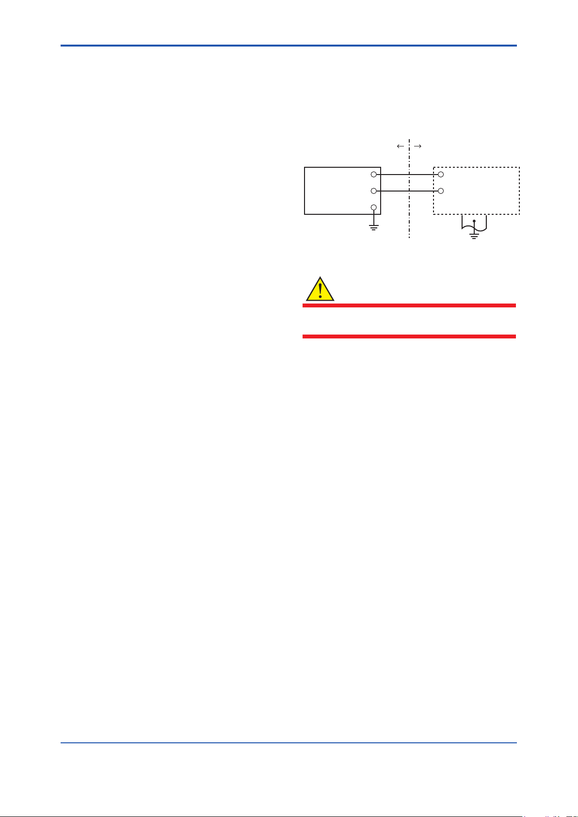
[Installation Diagram]
Hazardous Location
Transmitter
+
Supply
–
*1: In any safety barriers used the output current must be
limited by a resistor “R” such that Imaxout-Uz/R.
WARNING
Nonhazardous Location
+
Safety Barrier
–
F0206.ai
To satisfy IP66 or IP67, apply waterproof glands
to the electrical connection port.
b. ATEXFlameproofType
Caution for ATEX ameproof type.
Note 1. Model EJX Series pressure transmitters
with optional code /KF21 for potentially
explosive atmospheres:
• No. KEMA 07ATEX0109
• Applicable Standard: EN 60079-0:2006,
EN 60079-1:2004, EN 61241-0:2006,
EN 61241-1:2004
• Type of Protection and Marking Code: Ex d
IIC T6...T4, Ex tD A21 IP6x T85, T100, T120
• Group: II
• Category: 2G, 2D
• Enclosure: IP66 and IP67
• Temperature Class for gas-poof:
T6, T5, and T4
• Ambient Temperature for gas-proof:
–50 to 75°C (T6), –50 to 80°C (T5), and
–50 to 75°C (T4)
• Maximum Process Temperature (Tp.) for
gas-proof:
85°C (T6), 100°C (T5), and 120°C (T4)
• Maximum Surface Temperature for dustproof:
T85°C (Tamb.: –40* to 40°C, Tp.: 80°C)
T100°C (Tamb.: –40* to 60°C, Tp.: 100°C)
T120°C (Tamb.: –40* to 80°C, Tp.: 120°C)
* –15°C when /HE is specied.
*1
Page 3
<2.HandlingCautions>
Note 2. Electrical Data
• Supply voltage: 42 V dc max.
• Output signal: 4 to 20 mA
Note 3. Installation
• All wiring shall comply with local installation
requirement.
• The cable entry devices shall be of a certied
ameproof type, suitable for the conditions of
use.
Note 4. Operation
• Keep the “WARNING” label attached to the
transmitter.
WARNING: AFTER DE-ENERGIZING,
DELAY 5 MINUTES BEFORE OPENING.
WHEN THE AMBIENT TEMP.≥65°C, USE
HEAT-RESISTING CABLES≥90°C.
• Take care not to generate mechanical
sparking when accessing to the instrument
and peripheral devices in a hazardous
location.
Note 5. Maintenance and Repair
• The instrument modication or part
replacement by other than an authorized
representative of Yokogawa Electric
Corporation is prohibited and will void KEMA
Flameproof Certication.
WARNING
(3) Installation
WARNING
• All wiring shall comply with local installation
requirements and the local electrical code.
• There is no need for conduit seal in Division
1 and Division 2 hazardous locations
because this product is sealed at the factory.
(4) Operation
WARNING
• OPEN CIRCUIT BEFORE REMOVING
COVER. INSTALL IN ACCORDANCE WITH
THIS USER’S MANUAL
• Take care not to generate mechanical
sparking when access to the instrument and
peripheral devices in a hazardous location.
(5) MaintenanceandRepair
WARNING
The instrument modication or parts replacement
by other than an authorized Representative of
Yokogawa Electric Corporation is prohibited and
will void the certication.
To satisfy IP66 or IP67, apply waterproof glands
to the electrical connection port.
(2) ElectricalConnection
A mark indicating the electrical connection type is
stamped near the electrical connection port. These
marks are as followed.
Screw Size Marking
ISO M20 × 1.5 female
ANSI 1/2 NPT female
M
A or W
Location of the mark
F0208.ai
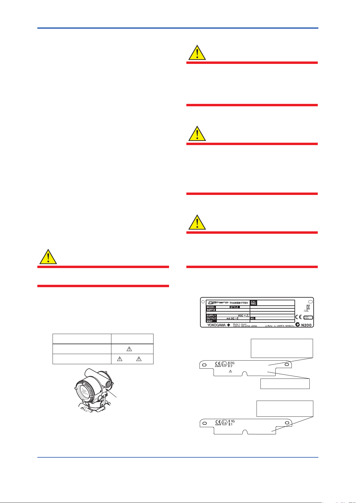
(6) NamePlate
● Name plate
● Tag plate for flameproof type
No. KEMA 07ATEX0109
Ex d IIC T6...T4, Ex tD A21, IP6X
Enlcosure : IP66, IP67
TEMP. CLASS T6 T5 T4
MAX PROCESS TEMP.(Tp.) 85 100 120 °C
Tamb. -50 to 75 80 75 °C
T85°C(Tamb.:40°C, Tp.:80°C),T100°C(Tamb.:60°C, Tp.:100°C),
T120°C(Tamb.:80°C, Tp.:120°C) Min.Tamb.:-40(-15)°C(for Dust)
D
WARNING
AFTER DE-ENERGIZING, DELAY 5 MINUTES
BEFORE OPENING.
WHEN THE AMBIENT TEMP. ≥ 65°C,
USE THE HEAT-RESISTING CABLES ≥ 90°C
● Tag plate for intrinsically safe type
No. KEMA 03ATEX1544 X
EEx ia IIC T4
IP66 and IP67
Tamb. -50 to 60°C MIN. Tamb.:-40(-15)°C(for DUST)
MAX. PROCESS TEMP.(Tp.) 120°C
T85°C(Tp.:80°C), T100°C(Tp.:100°C), T120°C(Tp.:120°C)
Ui=30V, Ii=200mA , Pi=0.9W, Ci=10nF, Li=0
D
F0209.ai
Page 4

<2.HandlingCautions>
91K819857 032
MODEL: Specied model code.
STYLE: Style code.
SUFFIX: Specied sufx code.
SUPPLY: Supply voltage.
OUTPUT: Output signal.
MWP: Maximum working pressure.
CAL RNG: Specied calibration range.
NO.: Serial number and year of production*1.
TOKYO 180-8750 JAPAN:
The manufacturer name and the address*2.
*1: The rst digit in the nal three numbers of the serial
number appearing after “NO.” on the nameplate
indicates the year of production. The following is an
example of a serial number for a product that was
produced in 2010:
The year 2010
*2: “180-8750” is a zip code which represents the
following address.
2-9-32 Nakacho, Musashino-shi, Tokyo Japan
(II)
ATEXCertication
(1) TechnicalData
a. ATEXIntrinsicallySafeType
Caution for ATEX Intrinsically safe type.
Note 1. EJX/EJA-E series pressure transmitters
with optional code /KS26 for potentially
explosive atmospheres:
• No. KEMA 04ATEX1116 X
• Applicable Standard: EN 60079-0:2009,
EN 60079-11:2007/EN 60079-11:2012,
EN 60079-26:2007, EN 60079-27:2008,
EN 61241-11:2006
Note 2. Ratings
Type of Protection and Marking Code:
Ex ia IIC/IIB T4 Ga
Ex ia IIIC T85°C T100°C T120°C Db
Group: II
Category: 1G, 2D
Ambient Temperature for EPL Ga: –40 to 60°C
Ambient Temperature for EPL Db: –30* to 60°C
* –15°C when /HE is specied.
Maximum Process Temperature (Tp.): 120°C
Maximum Surface Temperature for EPL Db.
T85°C (Tp.: 80°C)
T100°C (Tp.: 100°C)
T120°C (Tp.: 120°C)
Ambient Humidity:
0 to 100% (No condensation)
Degree of Protection of the Enclosure:
IP66 / IP67
Electrical Data
• When combined with Trapezoidal and
Rectangular output characteristic FISCO
model IIC barrier
Ui = 17.5 V, Ii = 380 mA, Pi = 5.32 W,
Ci = 3.52 nF, Li = 0 μH
• When combined with Linear characteristic
barrier
Ui = 24 V, Ii = 250 mA, Pi = 1.2 W,
Ci = 3.52 nF, Li = 0 μH
• When combined with Trapezoidal or
Rectangular output characteristic FISCO
model IIB barrier
Ui = 17.5 V, Ii = 460 mA, Pi = 5.32 W,
Ci = 3.52 nF, Li = 0 μH
Page 5

<2.HandlingCautions>
Note 3. Installation
• All wiring shall comply with local installation
requirements. (Refer to the installation
diagram)
Note 4. Maintenance and Repair
• The instrument modication or parts
replacement by other than authorized
representative of Yokogawa Electric
Corporation is prohibited and will void
DEKRA Intrinsically safe Certication.
Note 5. Special Conditions for Safe Use
WARNING
• In the case where the enclosure of the
Pressure Transmitter is made of aluminium,
if it is mounted in an area where the use of
category 1 G apparatus is required, it must
be installed such, that even in the event of
rare incidents, ignition sources due to impact
and friction sparks are excluded.
• Electrostatic charge may cause an explosion
hazard. Avoid any actions that cause the
generation of electrostatic charge, such as
rubbing with a dry cloth on coating face of
the product.
• In the case where the enclosure of the
Pressure Transmitter is made of aluminum,
if it is mounted in an area where the use of
category 2D apparatus is required, it shall
be installed in such a way that the risk from
electrostatic discharges and propagating
brush discharges caused by rapid ow of
dust is avoided.
• To satisfy IP66 or IP67, apply waterproof
glands to the electrical connection port.
• When the lightning protector option is
specied, the apparatus is not capable
of withstanding the 500V insulation test
required by EN60079-11.
This must be taken into account when
installing the apparatus.
Note 6. Installation Instructions
[Installation Diagram]
Terminator
Terminator
+
Safety Barrier
+
−
−
+
SUPPLY
−
+
−
+
−
Hazardous Location
Non-Hazardous Location
Pressure
Transmitter
Transmitter
Transmitter
• In the rating 1(*1), the output current of the
barrier must be limited by a resistor ‘Ra’ such
that Io = Uo/Ra.
• In the rating 2(*2), the output of the barrier
must be the characteristics of the trapezoid
or the rectangle and this transmitter can be
connected to Fieldbus equipment which are
in according to the FISCO model.
• The terminators may be built in by a barrier.
• More than one transmitter may be connected
to the power supply line.
• The terminator and the safety barrier shall be
certied.
Electrical data:
Maximum Input Voltage Ui: 24 V
Maximum Input Current Ii: 250 mA
Maximum Input Power Pi: 1.2 W
Maximum Internal Capacitance Ci: 3.52 nF
Maximum Internal Inductance Li: 0 μH
or
Maximum Input Voltage Ui: 17.5 V
Maximum Input Current Ii: 380 mA
Maximum Input Power Pi: 5.32 W
Maximum Internal Capacitance Ci: 3.52 nF
Maximum Internal Inductance Li: 0 μH
or
Maximum Input Voltage Ui: 17.5 V
Maximum Input Current Ii: 460 mA
Maximum Input Power Pi: 5.32 W
Maximum Internal Capacitance Ci: 3.52 nF
Maximum Internal Inductance Li: 0 μH
F0212.ai
*1:
Rating 1
*2:
Rating 2
Page 6

<2.HandlingCautions>
(2) ElectricalConnection
A mark indicating the electrical connection type is
stamped near the electrical connection port. These
marks are as follows.
Screw Size Marking
ISO M20 × 1.5 female
ANSI 1/2 NPT female
M
N or W
Location of the mark
F0214.ai
(3) Installation
WARNING
• All wiring shall comply with local installation
requirements and the local electrical code.
• There is no need for a conduit seal in
Division 1 and Division 2 hazardous
locations because this product is sealed at
the factory.
(4) Operation
WARNING
(6) NamePlate
Name plate
CAL
MODEL
SUFFIX
SUPPLY
OUTPUT
MWP
STYLE
mA DC
RNG
V DC
NO.
Made in Japan
TOKYO 180-8750 JAPAN
: Refer to USER'S MANUAL.
Tag plate for intrinsically safe type
No. KEMA 04ATEX1116 X
Ex ia IIC/IIB T4 Ga Ta:-40 to 60°C
Ex ia IIIC T85°C T100°C T120°C Db Ta:-30(-15) to 60°C
MAX PROCESS TEMP.(Tp.):120°C
T85°C(Tp.:80°C), T100°C(Tp.:100°C), T120°C(Tp.:120°C)
Enclosure: IP66/IP67
FISCO field device(IIC/IIB)
Entity parameters Ui=24V, Ii=250mA, Pi=1.2W, Ci=3.52nF, Li=0μH
D
WARNING
POTENTIAL ELECTROSTATIC CHARTGING HAZARD - SEE USER'S MANUAL.
F0213.ai
STYLE: Style code.
SUFFIX: Specied sufx code.
SUPPLY: Supply voltage.
OUTPUT: Output signal.
MWP: Maximum working pressure.
CAL RNG: Specied calibration range.
NO.: Serial number and year of production*1.
TOKYO 180-8750 JAPAN:
The manufacturer name and the address*2.
*1: The rst digit in the nal three numbers of the serial
number appearing after “NO.” on the name plate
indicates the year of production. The following is an
example of a serial number for a product that was
produced in 2010:
91K819857 032
• OPEN CIRCUIT BEFORE REMOVING
COVER. INSTALL IN ACCORDANCE WITH
THIS USER’S MANUAL
• Take care not to generate mechanical
sparking when accessing the instrument and
peripheral devices in a hazardous location.
(5) MaintenanceandRepair
WARNING
The instrument modication or part replacement
by other than an authorized Representative of
Yokogawa Electric Corporation is prohibited and
will void the certication.
The year 2010
*2: “180-8750” is the Zip code for the following address.
2-9-32 Nakacho, Musashino-shi, Tokyo Japan
Page 7

User’s
Manual
DPharp
Differential Pressure and
Pressure Transmitters
Manual Change No. 12-026
Please use this manual change for the manuals listed below.
For following models, the contents in the attached sheet should be used to replace the original contents.
1. Applicable manuals, sections, and corresponding items
IM No. and Edition Model
IM 01C25A01-01E (6th) EJX series and EJA-E series 3.3 (I)
IM 01C25H01-01E (8th) EJX118A, EJX438A, EJA118E, and EJA438E
IM 01C25T01-06E (3rd)
IM 01C25T03-01E (4th)
IM 01C25F01-01E (9th)
EJX series and EJA-E series
for HART communication protocol
EJX series and EJA-E series
for BRAIN communication protocol
EJX510A, EJX530A, EJX610A, EJX630A,
EJA510E, and EJA530E
Applicable Sections
of Each Manual
4.3 (I)
8.1 to 8.3 (III)
3.3.14 (II)
3.2.3 (20) (II)
9.4 (IV)
Corresponding
Items in the
Attached Section 2
Nov. 30, 2012
Page 8

2. Contents of change
(I) Transmitter Mounting (for EJA118E, EJX118A,
EJA438E, and EJX438A)
Please replace the original contents as follows when
the transmitter cannot be installed at least 600 mm
below the HP process connection.
IMPORTANT
The transmitter should be installed at least 600 mm below
the high pressure (HP) process connection to ensure a
positive head pressure of ll uid. Pay special attention to
vacuum applications.
If it can not be installed at least 600 mm below the HP
process connection, please use the equation below:
(P–P0)
h= × 0.102 [mm]
ds
h: Vertical height between the HP process connection
and the transmitter (mm)
h≤0: Install the transmitter at least h (mm) below the
HP process connection
h>0: Install the transmitter at most h (mm) above the
HP process connection
P: Pressure in the tank (Pa abs)
P0: Minimum working pressure limit of the transmitter (Pa
abs). See below table.
[For ll uid code A, B, C, D, E]
Wetted parts
material code
SW
SE
SY
HW
TW
UW
[For ll uid code 1, 2, 4]
Wetted parts
material code
SW
SE
SY
HW
TW
ds: Specic gravity of ll uid (at 25°C). See below table.
Fill uid code A, 1, 4 B C, 2 D E
ds: Specic
gravity
Capillary
length
1 to 5m 6790 3190
6 to 10m 10030 3520
1 to 5m 6790 3190
6 to 10m 10030 3520
1 to 5m 3190
6 to 10m 3520
1 to 5m 19150 6140
6 to 10m 8290
1 to 5m 9620 3620
6 to 10m 4210
1 to 5m 9540 4750
6 to 10m 6050
Capillary
length
1 to 5m 2570 320
6 to 10m 4680 530
1 to 5m 2570 320
6 to 10m 4680 530
1 to 5m 320
6 to 10m 530
1 to 5m 10220 2050
6 to 10m 3450
1 to 5m 4270 570
6 to 10m 960
1.07 0.94 1.09
Process connection size
code
2, 8 3 4,W
Process connection size
code
2, 8 3 4,W
1.90 to
1.92
1.09
(II) Capillary Fill Fluid Density Compensation (for
EJA118E, EJX118A, EJA438E, and EJX438A)
Please use the following constant value [B] of ll uid
for the capillary ll uid density compensation when ll
uid code 1, 2, or 4 is specied.
Table A. Constant value [B] of ll uid
Fill uid code 1, 2, 4
Constant value [B] mmH2O 0.75
2
Kgf/cm
kPa 0.00745
mbar 0.07453
atm 0.000074
inH2O 0.02992
psi 0.00108
mmHg 0.05592
0.0000745
Page 9

(III) Specications regarding ll uid code 1, 2, and 4 (for EJA118E, EJX118A, EJA438E, and EJX438A)
Please use the following additional contents for each item on the section 10, when ll uid code 1, 2, or 4 is specied.
8.1 Standard Specications (for EJA118E, EJX118A, EJA438E, and EJX438A)
Working Pressure Limits (Page 8-2): See below table.
Fill uid Working pressure
High temp. and high vacuum use
High vacuum use
0.013 kPa abs (0.0019 psi abs) to ange rating pressure
For atmospheric pressure or below, see gure 8.a, 8.b, and 8.c.
Transmitter ambient
temperature range
(for fill fluid code 1)
100(14.5)
Working
pressure
kPa abs
(psi abs)
10(1.4)
Process temperature
for fill fluid code 1
*1
Transmitter ambient
temperature range
(for fill fluid code 2)
Flange max.
working
pressure
Atmospheric
pressure
Working
pressure
kPa abs
(psi abs)
100(14.5)
10(1.4)
Process temperature
for fill fluid code 2
*1
Transmitter ambient
temperature range
(for fill fluid code 4)
Flange max.
working
pressure
Atmospheric
pressure
Working
pressure
kPa abs
(psi abs)
100(14.5)
10(1.4)
*1
Process temperature
for fill fluid code 4
Flange max.
working
pressure
Atmospheric
pressure
2.7(0.38)
1(0.14)
0.1(0.014)
0.013(0.0019)
0.01(0.0014)
-50 0 50 100 150 200 250 300 350
Temperature (°C)
Figure 8.a. Working Pressure and
Process Temperature
(Fill uid: silicone oil for high
temp. and high vacuum use)
2.7(0.38)
1(0.14)
0.1(0.014)
0.013(0.0019)
0.01(0.0014)
-50 0 50 100 150 200 250 300 350
Temperature (°C)
Figure 8.b. Working Pressure and
Process Temperature
(Fill uid: silicone oil for high
temp. and high vacuum use)
2.7(0.38)
1(0.14)
0.1(0.014)
0.013(0.0019)
0.01(0.0014)
-50 0 50 100 150 200 250 300 350
Figure 8.c Working Pressure and
*1: The upper ambient temperature limit is 50°(122°F) in the following combinations.
Process Temperature Limits (Page 8-2): See below table.
Code Process temperature Ambient temperature Working pressure Specic gravity
Silicone oil
(high temp. and
1
high vacuum use)
Silicone oil
(high temp. and
2
high vacuum use)
Silicone oil
(high vacuum use)
*1: In case of wetted parts material code TW (Tantalum), process temperature limit is up to 200°C (392°F).
*2: The upper ambient temperature limit is 50°C(122°F) in the following combinations.
4
–10 to 250°C*1
(14 to 482°F)
10 to 310°C
(50 to 590°F)
–10 to 100°C
(14 to 212°F)
–10 to 60°C*2
(14 to 140°F)
10 to 60°C*2
(50 to 140°F)
–10 to 60°C*2
(14 to 140°F)
0.013 kPa abs
(0.0019 psi abs)
to ange rating
pressure
Process connection style code Process connection size code
W (Flush type) 2 (2-inch) or 8 (1 1/2-inch)
E (Extension type) 3 (3-inch)
Temperature (°C)
Process Temperature
(Fill uid: silicone oil for high
vacuum use)
1.07
1.09
1.07
Page 10

8.2 Model and Sufx Codes (for EJA118E, EJX118A, EJA438E, and EJX438A)
Fill uid
-1……
-2……
-4……
*1: In case of wetted parts material code TW (Tantalum), process temperature limit is up to 200°C (392°F)
*2: Not applicable for wetted parts material code TW (Tantalum).
*3: Not applicable for process connection size code 8 (1 1/2-inch).
*4: Not applicable for ashing connection ring code 1, 2, A, and B.
*5: Not applicable for wetted parts material code UW (Titanium).
*6: The upper ambient temperature limit is 50°C (122°F) in the following combinations.
[Process temperature] [Ambient temperature]
High temp. and high vacuum use (Silicone oil) *1 –10 to 250°C –10 to 60°C
High temp. and high vacuum use (Silicone oil) *2 10 to 310°C 10 to 60°C
High vacuum use (Silicone oil) –10 to 100°C –10 to 60°C
Process connection style code Process connection size code
W (Flush type) 2 (2-inch) or 8 (1 1/2-inch)
E (Extension type) 3 (3-inch)
8.3 Optional Specications (for EJA118E, EJX118A, EJA438E, and EJX438A)
Teon lm* Diaphragm protection from sticky process uid by FEP Teon lm attached with
uorinated oil.
TF1
Operation range: 20 to 150°C, 0 to 2 MPa (Not applicable for vacuum service).
*: Applicable for the combination of ush type (process connection style code W) and ushing connection ring code 0.
Not applicable for Fill uid code 1, 2, or 4.
(IV) Dimensions for Process connection code 8 and 9 (for EJA510E, EJX510A, EJX610A, EJA530E, EJX530A, and
EJX630A)
9.4 Dimensions
With Process connections code 8 and 9
Regarding process connection code 8 and 9, the appearance of process connection part has been changed in
January, 2013.
The difference can be distinguished by the 3-digit marking engraved on the side of hexagonal nut part.
Marking (3 digits):
=Numerical character such as `3´: See figure (a).
=Alphabet such as `N´: See figure (b).
(a) (b)
24(0.94)
172
(6.77)
ø6
(0.24)
5(0.20) 20(0.78)
172
ø6
(0.24)
(6.77)
5(0.20)
 Loading...