

Page 1

User ’s
Manual
CA500, CA550
Multifunction Process
Calibrator
Getting Started Guide
IM CA500-02EN
1st Edition
Page 2

Product Registration
Thank you for purchasing YOKOGAWA products.
YOKOGAWA provides registered users with a variety of information and
services.
Please allow us to serve you best by completing the product registration
form accessible from our homepage.
http://tmi.yokogawa.com/
Page 3

Page 4
Thank you for purchasing the CA500/CA550 Multifunction Process Calibrator. This
Getting Started Guide focuses on the handling precautions, basic operations, and
specifications of the CA500 and CA550.
To ensure correct use, please read this manual thoroughly before operation. Keep
this manual in a safe place for quick reference.
List of Manuals
The following three manuals, including this one, are provided as manuals for the
CA500 and CA550.
Please read all manuals.
Manual Title Manual No. Description
CA500, CA550 Multifunction Process
Calibrator
User’s Manual
CA500, CA550 Multifunction Process
Calibrator
Getting Started Guide
CA500, CA550 Multifunction Process
Calibrator
User’s Manual
“전기용품 및 생활용품 안전관리법”
관련일차전지에 대한 대응
The “-EN”, “-Z1”, and “KO” in the manual number are the language code.
Contact information of Yokogawa offices worldwide is provided on the following
sheet.
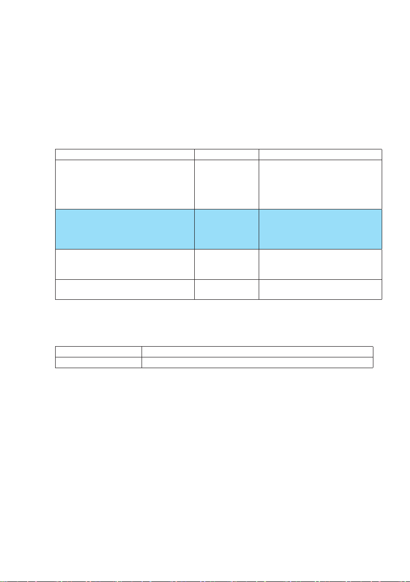
Manual No. Description
PIM113-01Z2 List of worldwide contacts
IM CA500-01EN The supplied CD contains the PDF
file of this manual. This manual
explains the instrument’s standard
features and how to use these
features.
IM CA500-02EN This document. This guide explains
the handling precautions, basic
operations, and specifications of
this instrument.
IM CA500-92Z1 A manual for China.
PIM 902-01KO A manual for Korea.
1st Edition: October 2019 (YMI)
All Rights Reserved, Copyright © 2019, Yokogawa Test & Measurement Corporation
Printed in Japan
IM CA500-02EN
1
Page 5

Notes
• The contents of this manual are subject to change without prior notice as a result
of continuing improvements to the instrument’s performance and functions. The
figures given in this manual may differ from those that actually appear on your
screen.
• Every effort has been made in the preparation of this manual to ensure the
accuracy of its contents. However, should you have any questions or find any
errors, please contact your nearest YOKOGAWA dealer.
• Copying or reproducing all or any part of the contents of this manual without the
permission of YOKOGAWA is strictly prohibited.
Trademarks
• Adobe and Acrobat are either registered trademarks or trademarks of Adobe
Systems Incorporated.
• HART is a registered trademark of FieldComm Group.
• In this manual, the ® and TM symbols do not accompany their respective
registered trademark or trademark names.
• Company and product names are trademarks or registered trademarks of their
respective holders.
Revisions
1st Edition: October 2019
2
IM CA500-02EN
Page 6

Checking the Contents of the Package
To prevent condensation, before opening the package, allow it to adjust to the
ambient temperature. In particular, if you move the package from a cool location to a
hot location, allow it to adjust to the ambient temperature for at least an hour before
opening the package.
Unpack the box, and check the following before operating the instrument. If the
wrong items have been delivered, if items are missing, or if there is a problem with
the appearance of the items, contact your nearest YOKOGAWA dealer.
CA500/CA550
Check that the product that you received is what you ordered by referring to the
model name on the name plate on the rear panel of the main unit. For reference, the
model name and specifications of the products are listed below.
MODEL Suffix Code* Description
CA500 -F1
CA550
* For products whose suffix code contains “Z,” an exclusive manual may be
included. Please read it along with the standard manual.
** A model without either the HART or BRAIN communication function. This suffix
code is always added for the CA500.
*** Either F2 or F3 is always added for the CA550.
Please contact your dealer for sales area.
HART/BRAIN communication function will be supported in the near future.
-F2
-F3
**
***
***
Multifunction process calibrator
Multifunction process calibrator (with HART
communication function)
HART/BRAIN (CA550 only)
HART (CA550 only)
No. (Instrument number)
When contacting the dealer from which you purchased the instrument, please give
them the instrument number.
IM CA500-02EN
3
Page 7

Standard Accessories
The following accessories are included. Check that all contents are present and
undamaged.
No Name Model or
Part No.
1 Lead cable for source 98020 1 set 1 red, 2 black, 1.7 m
2 Source/measurement
lead cable
3 Binding post (red-black
pair)*
4 Binding post (red-red
pair)*
5 USB cable A1421WL 1 pc. USB Type A to Type B, 2 m
6 Shoulder strap B8070CY 1 pc.
7 Soft case B8080FQ 1 pc. For accessories
8 Batteries - 4 pcs. AA alkaline batteries (LR6)
9 CD A1031US 1 copy User’s Manual (PDF)
10 Manuals IM CA500-02EN
98035 1 pc. 3 red, 1 black, 1.7 m
99045 1 set One short plate included
99046 1 set One short plate included
IM CA500-92Z1
PIM 902-01KO
PIM 113-01Z2
* Before using the included binding post, remove the short plate attached to the
binding post.
Standard accessories are not covered by warranty.
Quantity Notes
7 mm fork terminal to alligator clip
L plug terminal to alligator clip
1 copy
each
This manual.
A manual for China.
A manual for Korea.
Not Included depending on the
specifications.
List of contacts
Manual CD
The English folder in the CD contains the PDF files shown below. The CD also
contains Japanese manuals.
File Name Manual Title Manual No.
CA500,CA550 Users_manual.pdf CA500, CA550 Multifunction
Process Calibrator User’s
Manual
IM CA500-01EN
To view the above PDF data, you need Acrobat Reader or a software application
that can open PDF.
4
IM CA500-02EN
Page 8

Optional Accessories (Sold separately)
The optional accessories below are available for purchase separately. For
information about ordering accessories, contact your nearest YOKOGAWA dealer.
Item Model Min. Q’ty Specifications
Lead cable 98064 1 1 red, 1 black, 1.7 m
L plug terminal to alligator clip
Grabber clip 98026 1 1 red-black pair, 2 m, separate type
RJ sensor 90080 1 Pt100 JIS AA class or equivalent,
Thermometer operating temperature range: -10°C
to +55°C
8-polar miniDin connector, 1.5 m shielded cable
Fork terminal (M3 terminal block compatible)
Thermocouple Mini
Plug Set 1
Thermocouple Mini
Plug Set 2
Soft Carrying Case SU2006A 1
* Accessories (sold separately) are not covered by warranty.
90040 1 K (yellow)/ E (violet)/ J (black)/ T (blue)/R•S (green)/
B•U (white)/ G (red, green)/D (red, white)/ C (red)/
N (orange)
90045 1 K (yellow)/ E (violet)/ J (black)/ T (blue)
IM CA500-02EN
5
Page 9
Conventions Used in This Guide
Prefixes k and K
This manual distinguishes prefixes k and K used before units as follows:
k: Denotes 1000. Example: 100 kS/s (sample rate)
K: Denotes 1024. Example: 720 KB (file size)
Displayed Characters
Bold characters in procedural explanations are used to indicate panel keys and soft
keys that are used in the procedure and menu items that appear on the screen.
Notes and Cautions
The notes and cautions in this guide are categorized using the following symbols.
Improper handling or use can lead to injury to the user or damage to the
instrument. This symbol appears on the instrument to indicate that the user
must refer to the user’s manual for special instructions. The same symbol
appears in the corresponding place in the user’s manual to identify those
instructions. In the manual, the symbol is used in conjunction with the word
“WARNING” or “CAUTION.”
WARNING
CAUTION
Note
French
Une manipulation ou une utilisation incorrectes risquent de blesser
AVERTISSEMENT
6
Calls attention to actions or conditions that could cause serious
or fatal injury to the user, and precautions that can be taken to
prevent such occurrences.
Calls attention to actions or conditions that could cause light
injury to the user or damage to the instrument or user’s data,
and precautions that can be taken to prevent such occurrences.
Calls attention to information that is important for the proper operation of the
instrument.
l’utilisateur ou d’endommager l’instrument. Ce symbole apparaît sur
l’instrument pour indiquer à l’utilisateur qu’il doit se reporter au manuel
de l’utilisateur afin d’y lire les instructions spécifiques correspondantes.
Ce même symbole apparaît à la section correspondante du manuel de
l’utilisateur pour signaler lesdites instructions. Dans le manuel de l’utilisateur,
ce symbole est accompagné des termes AVERTISSEMENT et ATTENTION.
Attire l’attention sur des gestes ou des conditions
susceptibles de provoquer des blessures graves (voire
mortelles), et sur les précautions de sécurité pouvant
prévenir de tels accidents.
IM CA500-02EN
Page 10

ATTENTION
Attire l’attention sur des gestes ou des conditions
susceptibles de provoquer des blessures légères
ou d’endommager l’instrument ou les données
de l’utilisateur, et sur les précautions de sécurité
susceptibles de prévenir de tels accidents.
IM CA500-02EN
7
Page 11
Safety Precautions
This product is designed to be used by a person with specialized knowledge. The
general safety precautions described herein must be observed during all phases
of operation. If the product is used in a manner not specified in this guide, the
protection provided by the product may be impaired. YOKOGAWA assumes no
liability for the customer’s failure to comply with these requirements.
This manual is part of the product and contains important information. Store
this manual in a safe place close to the instrument so that you can refer to it
immediately. Keep this manual until you dispose of the instrument.
The following symbols are used on this instrument.
Handle with care. Refer to the user’s manual or service manual. This symbol
appears on dangerous locations on the instrument which require special
instructions for proper handling or use. The same symbol appears in the
corresponding place in the manual to identify those instructions.
Direct current Functional ground
French
À manipuler délicatement. Toujours se reporter aux manuels d’utilisation et
d’entretien. Ce symbole a été apposé aux endroits dangereux de l’instrument
pour lesquels des consignes spéciales d’utilisation ou de manipulation ont
été émises. Le même symbole apparaît à l’endroit correspondant du manuel
pour identifier les consignes qui s’y rapportent.
Courant direct Borne de terre fonctionnelle
Failure to comply with the precautions below could lead to injury
or death or damage to the instrument.
WARNING
Use the Instrument Only for Its Intended Purpose
This instrument sources and measures DC voltage and DC
current. Use this instrument only for these purposes.
Check the Physical Appearance
Do not use the instrument if there is a problem with its physical
appearance.
Batteries
• Do not mix new and old batteries or mix different brands or types
of batteries. The batteries may leak, heat up, or burst due to their
characteristic differences.
• Never replace the batteries with the main unit turned on.
8
IM CA500-02EN
Page 12

Do Not Operate in an Explosive Atmosphere
Do not use this instrument in the presence of flammable gases or
vapors. Doing so is extremely dangerous.
Do Not Remove the Covers or Disassemble or Alter the
Instrument
Only qualified YOKOGAWA personnel may remove the covers and
disassemble or alter the instrument.
The inside of the instrument is dangerous because parts of it have
high voltages.
Measurement Category
The measurement category of this instrument’s signal input
terminals is Other (O). Do not use it to measure the main power
supply or for Measurement Categories II, III, and IV.
Install or Use the Instrument in Appropriate Locations
• This instrument is not dust-proof or water-proof. Do not install or
use this instrument outdoors, in a location subject to rain or water,
or a location full of dust.
• Install the instrument so that you can immediately turn off the
power if an abnormal or dangerous condition occurs.
External Connections
Before connecting the instrument to the DUT or external control
circuit or before touching a circuit, turn off its power and check
that it has no voltage. To prevent electric shock and accidents,
connect the ground of the probes or input connectors to the ground
potential of the device under measurement.
IM CA500-02EN
Handling
• Never use the instrument if the instrument or your hand is wet or
when condensation or other water droplets are on the instrument.
• Never open the battery cover while a measurement is in progress.
Signal Input
Do not apply signals that exceed the measurement range.
Lead cable
• Use the probes supplied by Yokogawa for this instrument.
• Do not use deteriorated or damaged lead cables.
• Check the conduction of the lead cable before using it.
• Do not use the lead cable for source (98020) to make
measurements.
When making a measurement, be sure to use the source/
measurement lead cable (98035).
9
Page 13

Accessories
• Use the accessories specified in this manual. Moreover, use the
accessories of this product only with Yokogawa products that
specify them as accessories.
• Use the accessories of this product within the rated range of each
accessory. When using several accessories together, use them
within the specification range of the accessory with the lowest
rating.
• Do not use faulty accessories.
Damaged Cable
If the cable is torn and the inner metal is exposed or if a color
different from the outer sheath appears, stop using the cable
immediately.
CD
Never play this CD, which contains the user’s manuals, in an audio
CD player. Doing so may cause loss of hearing or speaker damage
due to the high-volume sound that may be produced.
CAUTION
Operating Environment Limitations
This product is classified as Class A (for use in industrial
environments). Operation of this product in a residential area may
cause radio interference, in which case the user will be required to
correct the interference.
10
Operating Environment
This instrument is not dust-proof or water-proof.
French
AVERTISSEMENT
Ne faites de cet équipement que l’utilisation pour laquelle il a
été conçu
Cet équipement est un calibreur pour l’équipement de mesure de
tension/courant, pour l’équipement de termocouple/mesure et pour
l’équipement de RTD/mesure. Utilisez cet équipement à des fins de
calibrage uniquement.
Inspecter l’apparence physique
Ne pas utiliser l’instrument si son intégrité physique semble être
compromise.
IM CA500-02EN
Page 14

Batteries
• Ne pas mélanger des batteries neuves et des batteries usagées,
ni des batteries de marques ou de types différents. Les batteries
risquent de fuir, de chauffer ou d’éclater en raison de leurs
différentes caractéristiques.
• Ne jamais remplacer les batteries lorsque la mesure est en cours.
Ne pas utiliser dans un environnement explosif
Ne pas utiliser l’instrument en présence de gaz ou de vapeurs
inflammables. Cela pourrait être extrêmement dangereux.
Ne pas retirer le capot, ni démonter ou modifier l’instrument
Seul le personnel YOKOGAWA qualifié est habilité à retirer le capot
et à démonter ou modifier l’instrument. Certains composants à
l’intérieur de l’instrument sont à haute tension et par conséquent,
représentent un danger.
Catégorie de mesure
La catégorie de mesure des terminaux d’entrée de signal de ce
produit est Autre(O). Ne pas l’utiliser pour mesurer l’alimentation
électrique, ni pour les catégories de mesureII, III et IV.
Installer et utiliser l’instrument aux emplacements appropriés
• Cet instrument n’est pas étanche à la poussière ni à l’eau. Ne pas
installer, ni utiliser cet instrument à l’extérieur, dans un endroit
exposé à la pluie ou à l’eau, ou dans un endroit poussiéreux.
• Installer l’instrument de manière à pourvoir immédiatement le
débrancher du secteur en cas de fonctionnement anormal ou
dangereux
IM CA500-02EN
Connexions Externes
Avant de brancher cet instrument au dispositif en essai (DUT) ou au
circuit de commande externe, ou avant de toucher un circuit, mettre
l’instrument hors tension et vérifier l’absence de tension. Pour éviter
un choc électrique ou des accidents, brancher la terre des sondes
ou les connecteurs d’entrée au potentiel de terre de l’appareil faisant
l’objet de la mesure.
Manipulation
• Ne jamais utiliser cet instrument si l’instrument ou votre main est
mouillé, ou la condensation ou la goutte d’eau sont adhérées à
l’instrument.
• Ne jamais ouvrir le couvercle de batterie pendant la mesure est en
cours.
Signal d’Entrée
Ne pas appliquer de signaux qui dépassent la plage de mesure.
11
Page 15

Câble de Raccordement
• Utiliser les sondes fournies par Yokogawa pour cet instrument.
• Ne pas utiliser des câbles de raccordement détériorés ou
endommagés.
• Vérifier la conduction de câble de raccordement avant l’utiliser.
• Ne pas utiliser le câble de raccordement pour la source (98020)
pour faire des mesures.
Lors de la mesure, veiller à utiliser le câble de raccordement de la
source/mesure (98035).
Accessoires
• Utiliser les accessoires spécifiés dans ce manuel. En outre, utiliser
les accessoires de ce produit uniquement avec des produits
Yokogawa pour lesquels ils sont spécifiés comme accessoires.
• Utiliser les accessoires de ce produit dans la plage nominale de
chaque accessoire. Lors de l’utilisation de plusieurs accessoires
ensemble, les utiliser dans la plage spécifiée de l’accessoire avec
la tension nominale la plus basse.
• Ne pas utiliser d’accessoires défectueux.
Câble de signal endommagé
Si le câble de signal est déchiré et que le métal intérieur est exposé
ou si une couleur différente de la gaine externe est visible, arrêter
immédiatement d’utiliser ce câble.
CD
Ce CD contient les manuels d’utilisation. Ne jamais insérer ce CD
dans un lecteur de CD audio. Cela pourrait entraîner une perte
d’audition ou l’endommagement des enceintes en raison du volume
potentiellement élevé des sons produits.
ATTENTION
Limitations relatives à l’environnement opérationnel
Ce produit est un produit de classe A (pour environnements
industriels). L’utilisation de ce produit dans un zone résidentielle peut
entraîner une interférence radio que l’utilisateur sera tenu de rectifier.
Environnement Opérationnel
Cet instrument n’est pas étanche à la poussière ni à l’eau.
12
IM CA500-02EN
Page 16
Regulations and Sales in Each Country or Region
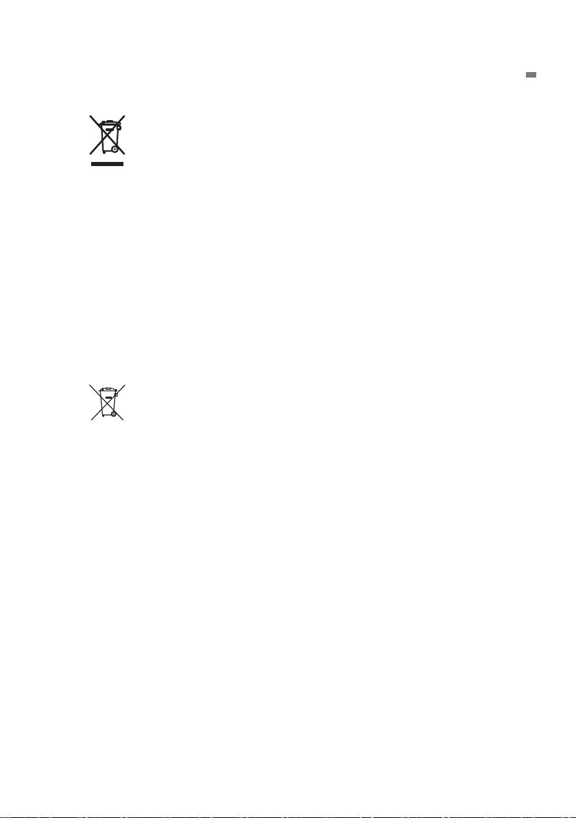
Waste Electrical and Electronic Equipment
Waste Electrical and Electronic Equipment (WEEE), Directive
(This directive is valid only in the EU.)
This product complies with the WEEE directive marking
requirement. This marking indicates that you must not discard this
electrical/electronic product in domestic household waste.
Product Category
With reference to the equipment types in the WEEE directive, this
product is classified as a “Monitoring and control instruments”
product.
When disposing products in the EU, contact your local Yokogawa
Europe B.V. office.
Do not dispose in domestic household waste.
EU Battery Directive
(This directive is valid only in the EU.)
Batteries are included in this product. This marking indicates
they shall be sorted out and collected as ordained in EU Battery
Directive.
Battery type:
1. Lithium battery
You cannot replace batteries by yourself. When you need to
replace batteries, contact your local Yokogawa Europe B.V.office.
2. Alkaline battery
When disposing of alkaline batteries, follow the domestic law
concerning disposal. Take the proper action to dispose batteries
in accordance with the established collection system in the
European Economic Area. For the battery removal procedure,
see page 31.
Authorized Representative in the EEA
Yokogawa Europe B.V. is the authorized representative of Yokogawa Test &
Measurement Corporation for this product in the EEA. To contact Yokogawa Europe
B.V., see the separate list of worldwide contacts, PIM 113-01Z2.
Disposing of the Instrument
When disposing of the instrument, follow the laws and ordinances of your country or
region.
IM CA500-02EN
13
Page 17

Contents
Product Registration .............................................................................................................. i
Checking the Contents of the Package ................................................................................ 3
Conventions Used in This Guide ..........................................................................................6
Safety Precautions ............................................................................................................... 8
Regulations and Sales in Each Country or Region ............................................................ 13
1 Component Names and Functions
1.1 Front Panel ..............................................................................................................15
1.2 Side Panel and Rear Panel......................................................................................17
1.3 Display ..................................................................................................................... 18
2 Preparation before Use
2.1 Handling Precautions ............................................................................................... 21
2.2 Installing the Instrument ........................................................................................... 23
2.3 Connecting Cables ...................................................................................................26
2.4 Loading and Removing Batteries ............................................................................. 31
2.5 Supplying Power through the USB Terminal ............................................................ 33
2.6 Turning the Power On and Off .................................................................................34
2.7 Setting the Date and Time .......................................................................................35
3 Common Operations
3.1 Opening and Closing Setup Screens ....................................................................... 37
3.2 Setup Screen Operation ..........................................................................................37
3.3 Selection Menu Operation .......................................................................................38
3.4 Specifying Values .....................................................................................................38
3.5 Setting Alphanumeric Characters ............................................................................ 39
4 Troubleshooting, Maintenance, and Inspection
4.1 Troubleshooting .......................................................................................................40
4.2 Error Codes, Error Messages, and Corrective Actions ............................................41
4.3 Displaying Instrument Information ...........................................................................42
4.4 Recommended Replacement Parts, Consumable Parts, and Calibration ............... 42
5. Specifications
5.1 DC Voltage, DC Current, Resistance and Pulse Source ........................................43
5.2 DC Voltage, DC Current, Resistance and Pulse Measurement ..............................45
5.3 Temperature Measurement (TC) and Thermocouple Calibration Voltage Source ...47
5.4 Temperature Measurement (RTD) and Resistance Source for RTD Calibration ..... 60
5.5 Common Specifications ........................................................................................... 63
5.6 General Specifications ............................................................................................. 64
14
IM CA500-02EN
Page 18
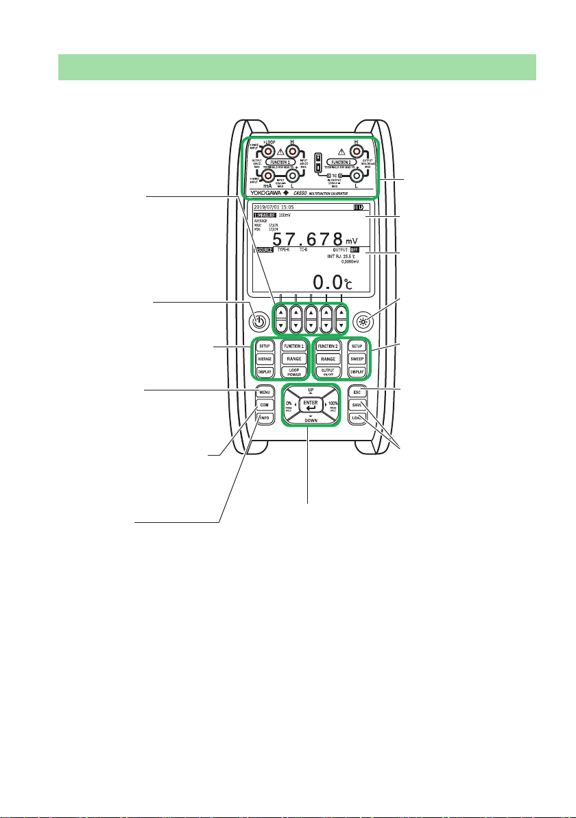
1 Component Names and Functions
1.1 Front Panel
I/O terminals
Arrow keys
Increases or decreases the
number at the
corresponding digit or
selects the corresponding
item from the selection
menu
POWER key
Turns the power on and off
Function 1 setup keys
(see page 16)
MENU key
Displays an
instrument setup
menu
COM key (CA550 only)
Performs HART/BRAIN
(to be supported in the
near future)
INFO key
Displays information about the
instrument and the wiring
diagram of the specified
function
Cursor keys and ENTER key
(see page 16)
Display area
(Function 1)
Display area
(Function 2)
Light key
Turns on the display
light
Function 2 setup
keys
(see page 16)
ESC key
Cancels settings or
returns to the previous
screen
File key
Saves and loads
measured values
IM CA500-02EN
15
Page 19
1 Component Names and Functions
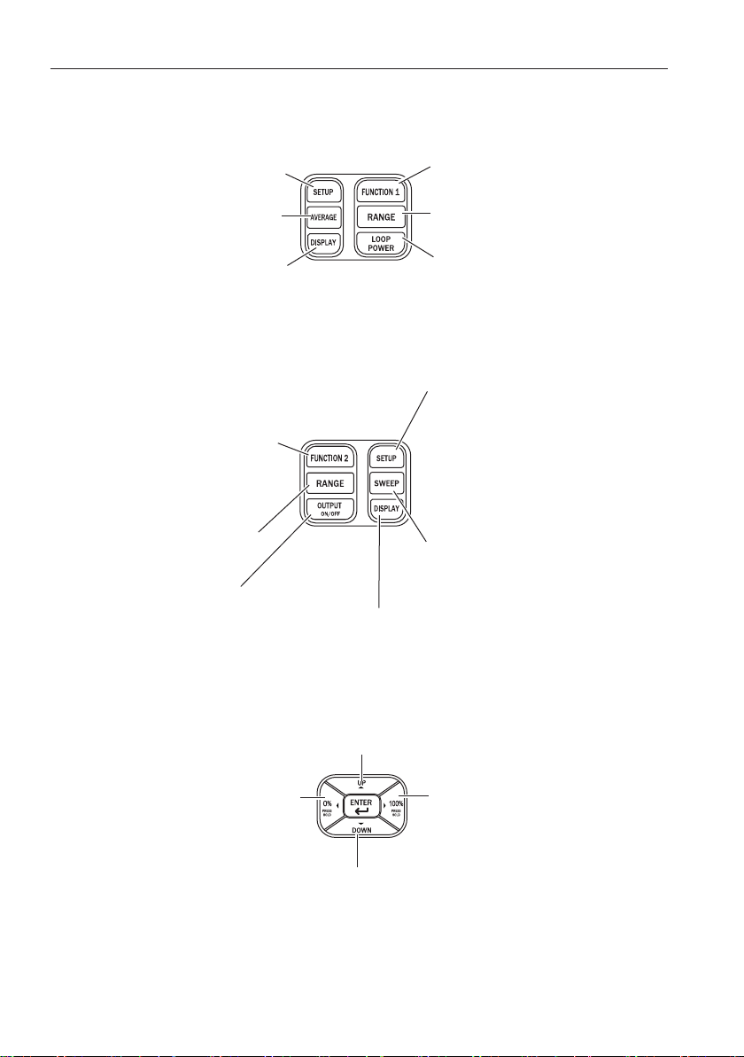
Function Set Keys
Function 1 setup keys
Sets the 0 and 100% value
and the pulse contact input
on/off
Turns on/off the moving
average function and the
max/min display
Turns on/off the 0 and 100%
value displays and selects
whether to show the
measured value or percentage
on the main display
Function 2 setup keys
Selects thermocouple
measurement and source
function (voltage, current,
resistance, RTD, pulse,
thermocouple, off)
Selects the source
range
Turns the source
on or off
Selects the measurement
function (voltage, current,
resistance, RTD, pulse, off)
Selects the measurement
range
Turns on and off the loop
power supply (when current is
being measured)
Sets the 0 and 100% value,
number of divisions, sweep
settings, temperature
measurement/source items
(thermocouple terminal
selection, burnout, etc.), and
pulse source items (amplitude,
pulse count, pulse contact
output on/off)
Selects the sweep to be
executed (linear, step,
program)
Turns on and off the 0 and 100% value displays
and selects whether to show the source value
or percentage on the main display
Cursor Keys and ENTER Key
On screens displaying the source value, the following functions can be executed.
Steps up the source value according to the specified number of divisions
Sets the source value to the
0% value. To set the 0%
value, hold down the key. The
displayed source value is set
to 0%.
Steps down the source value according to the specified
number of divisions
On various setup menus, use the cursor keys to select settings and the ENTER key
to confirm the settings.
16
Sets the source value to the
100% value. To set the 100%
value, hold down the key. The
displayed source value is set to
100%.
IM CA500-02EN
Page 20
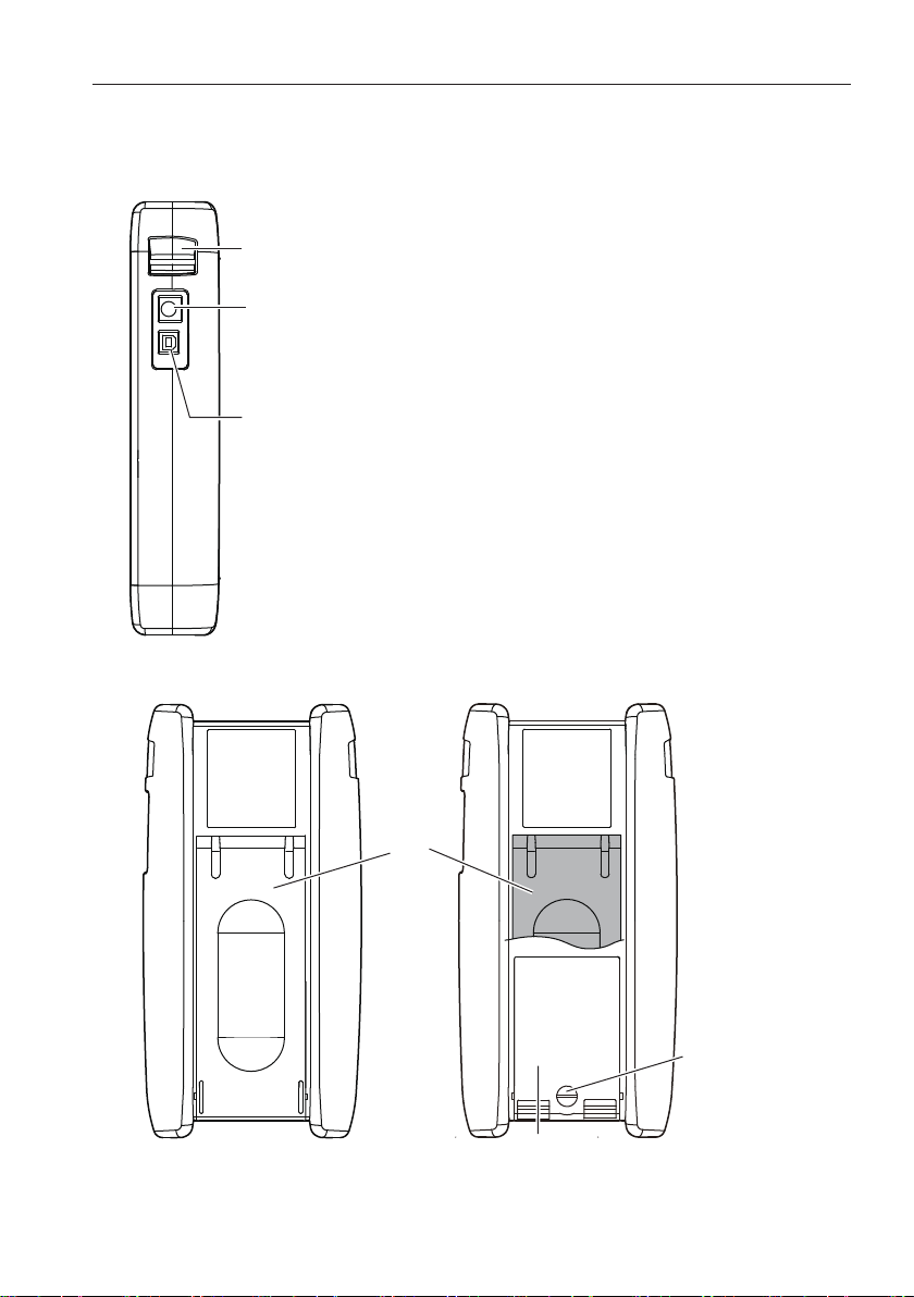
1.2 Side Panel and Rear Panel
Side panel
Shoulder strap fastening area (see page 25)
RJ sensor connector
Connect an external RJ sensor(sold
separately).
USB port (type B)
Can be used to control the instrument remotely
from a PC and supply power to the instrument.
On the CA550, data control can be performed
according to the USB mass storage class.
Rear Panel
1 Component Names and Functions
IM CA500-02EN
Stand
Battery cover
lock key
Battery cover
17
Page 21

1 Component Names and Functions
1.3 Display
Displayed when pulse contact input is on and
function is set to PULSE
Average display
Displayed when auto power-off is on
Measurement
range
Date/time
Function 1
display
Function 2
display
Source/measurement range
Displayed when pulse contact output is on and
function is set to PULSE
Sweep mode
State of sweep
0, 100% value
Displayed when display
light is on
Displayed when
communication
resistance is on
0, 100% value
Thermocouple type
Power supply state
USB:
Battery:
Source state
Sub display 3
Sub display 2
Sub display 1
Main display
(source value
and unit)
USB
(level)
LOOP POWER
output state
Sub display 3
Sub display 2
Sub display 1
Main display
(measured value
and unit)
Function 1 and 2 Displays
The top area of the screen shows the function 1 information and the bottom area
the function 2 information.
18
IM CA500-02EN
Page 22

1 Component Names and Functions
Main Displays and Sub Displays
Each time you press the DISPLAY key of function 1 or 2, the main display switches
between showing the physical value and percentage. When the main display is
showing the physical value, sub display 1 shows the percentage, and vice versa.
Sub display 2 shows the thermoelectromotive force of a thermocouple, the
resistance of an RTD.
Sub display 3 shows the temperature of a reference junction or the amplitude
voltage.
The 0% and 100% values can be shown or hidden using DISPLAY.
Function Main display Sub display 1 Sub display 2 Sub display 3
DC voltage Measure value/
source value
Percentage Measure value/
DC current Measure value/
source value
Percentage Measure value/
Resistance Measure value/
source value
Percentage Measure value/
Thermocouple Measure value/
source value
temperature
(
Percentage Measure value/
RTD Measure value/
source value
temperature
(
Percentage Measure value/
Frequency Measure value/
source value
Percentage Measure value/
Percentage — —
— —
source value
Percentage — —
— —
source value
Percentage — —
— —
source value
Percentage Measure value/
source value
)
source value
temperature
(
Percentage Measure value/
)
source value
temperature
(
Percentage — —
source value
voltage
(
)
Measure value/
source value
voltage
)
(
)
source value
(resistance )
Measure value/
source value
(resistance )
)
— —
Temperature monitor
(reference junction
temperature)
Temperature monitor
(reference junction
temperature)
—
—
IM CA500-02EN
19
Page 23

1 Component Names and Functions
Select Menu
When setting a function, available options are displayed at the bottom of the screen.
Press the arrow key corresponding to the option you want to select.
For two-row selection menus, the up arrow key corresponds to the top area and the
down arrow key to the bottom area.
Select menu
Initializes the settings
Confirms the settings and
closes the setup screen
20
IM CA500-02EN
Page 24

2 Preparation before Use
2.1 Handling Precautions
Safety Precautions
If you are using this instrument for the first time, make sure to thoroughly read the
safety precautions given on pages 8 to 12.
Unplug If Abnormal Behavior Occurs
If you notice smoke or unusual odors coming from the instrument, immediately
turn off the power, remove the batteries if possible, and contact your nearest
YOKOGAWA dealer. Also, turn off the power to source/measurement targets that
are connected to the input terminals.
Do Not Remove the Case
Do not remove the case from the instrument. Some parts of the instrument
use high voltages and are extremely dangerous. For internal inspection and
adjustment, contact your nearest YOKOGAWA dealer.
Operating Environment and Conditions
This instrument complies with the EMC standard under specific operating
environment and operating conditions. If the installation, wiring, and so on are
not appropriate, the compliance conditions of the EMC standard may not be met.
In such cases, the user will be required to take appropriate measures.
General Handling Precautions
Do Not Place Objects on Top of the Instrument
Never place other instruments or objects containing water on top of the
instrument, otherwise a breakdown may occur.
Do Not Subject the Inputs and Outputs to Mechanical Shock
If the input connectors or adapters are subjected to mechanical shock, they may
be damaged. The instrument may not perform measurements correctly due to
damage or deformation that is not visible to the naked eye.
Do Not Damage the LCD
Because the LCD can be easily scratched, do not allow any sharp objects near
it. In addition, observe the following:
• Do not apply vibration or shock.
• Do not apply strong shock to the LCD.
• Do not place objects on the LCD.
IM CA500-02EN
21
Page 25

2 Preparation before Use
Remove the Batteries during Extended Non-Use
Remove the batteries from the main unit.
When Carrying the Instrument
First, turn off the device under measurement. Next, turn off the instrument.
When USB power supply is in use, remove the USB cable. Then, remove all the
cables.
Attaching the Shoulder Strap
Attach the shoulder belt to prevent dropping the instrument. For instructions on
how to attach the shoulder strap, see page 25.
When Cleaning the Instrument
When cleaning the case or the operation panel, gently wipe the outer surface
using a damp, well-wrung, soft, clean cloth. The instrument can malfunction if
water enters inside the instrument.
Do not use chemicals such as benzene or thinner. These can cause discoloring
and deformation.
Other Precautions
• Keep electrically charged objects away from the input terminals. They may
damage the internal circuitry.
• Do not cover the case or operation panel with a volatile material or leave
rubber or vinyl products in contact with the case or operation panel for a long
time.
Notes on generating accurate source
In a small output range, the error in the source value may become large due to
changes in the temperature of the output terminals caused by (1) the conductor
making contact when wiring, (2) changes in the temperature inside the instrument
due to 4-20mA simulation or loop power, or (3) the movement of the surrounding air.
In such situations, wait until the output stabilizes.
In addition, while the instrument is generating output, be careful to keep the output
terminal temperature from changing due to the effects air conditioning, other heat
sources, and the like.
Storage Precautions
Avoid the following kinds of places for storing the instrument:
• Where the temperature falls outside the storage temperature and humidity ranges
• In direct sunlight or near heat sources
• Where an excessive amount of soot, steam, dust, or corrosive gas is present
• Where the level of mechanical vibration is high
• On an unstable surface
• Where an excessive amount of soot, dust, salt, or iron is present
22
IM CA500-02EN
Page 26

2.2 Installing the Instrument
WARNING
• Install the instrument so that you can immediately turn off the
power if an abnormal or dangerous condition occurs.
• Do not use the instrument to measure locations that fall under
Measurement Categories II, III, and IV.
CAUTION
This instrument is equipped with voltage and current source and
measurement features. Do not use the instrument when it is wet.
Doing so may damage the instrument.
French
AVERTISSEMENT
• Installer l’instrument de manière à pourvoir immédiatement le
débrancher du secteur en cas de fonctionnement anormal ou
dangereux.
• N’utilisez pas cet équipement pour mesurer des points tombant
sous les catégories de mesure II, III et IV.
2 Preparation before Use
ATTENTION
• Cet équipement est doté de fonctions de mesure et de source
de courant et de tension. N’utilisez pas l’équipement lorsqu’il est
mouillé. Le cas échéant, un endommagement de l’équipement
risquerait de se produire.
IM CA500-02EN
23
Page 27

2 Preparation before Use
Installation Conditions
Install the instrument in a place that meets the following conditions.
• Operating Altitude and Ambient Temperature and Humidity
• Use the instrument in the following environment.
• Ambient temperature -10°C to 50°C
• Ambient humidity 80% RH or less for -10°C to 40°C, 50% RH or less
for over 40°C
No condensation
• Operating altitude Up to 2000 m
Note
• To ensure high accuracy, operate the instrument within 23°C ± 5°C.
• When using the instrument in a place where the ambient humidity is 30% or less, take
measures to prevent static electricity such as using an anti-static mat.
• Condensation may occur if the instrument is moved to another place where the ambient
temperature or humidity is higher, or if the temperature changes rapidly.
In such cases, allow the instrument adjust to the new environment for at least an hour
before using the instrument.
Install the instrument in a proper location by referring to “Safety Precautions” on
page 8.
Do not install the instrument in the following places, as it can cause incorrect
measurements or damage the instrument.
• In direct sunlight or near heat sources
• In an environment with excessive amounts of soot, steam, dust, or corrosive gas
• Near strong magnetic field sources
• Near noise sources, such as high-voltage equipment or power lines
• Where the level of mechanical vibration is high
• On an unstable surface
• Outdoors or in locations subject to rain or water
24
IM CA500-02EN
Page 28

2 Preparation before Use
Measurement Category
The measurement category of this instrument is Other (O).
Measurement
Category
O(None, Other) Other circuits that are not directly
CAT II For measurements performed on circuits
CAT III For measuring facility circuits Distribution boards, circuit
CAT IV For measurements performed on power
Description Notes
Circuits that are not powered
connected to the mains.
that are connected to low-voltage
installations
source circuits
from the mains
Household appliances,
portable tools, etc.
breakers, etc.
Entrance cables, cable
systems, etc.
The estimated transient overvoltage that may appear at the CA500 and CA550
signal input terminals is 500 V.
Fastening the Shoulder Strap
Fasten the shoulder strap to the strap fastening area at the top section on each side
of the instrument.
Pass the shoulder strap through the fastening area and then the buckle as shown in
the figure. Attach the left and right sides in the same manner.
Pass the belt back
through the buckle again
and tighten it.
Buckle
IM CA500-02EN
25
Page 29

2 Preparation before Use
2.3 Connecting Cables
WARNING
Maximum Voltage Application Between Terminals And Earth
The maximum voltage application between measurement terminals
and earth is 50 VDC, and that of the source terminals is 30 VDC. To
prevent electric shock, do not exceed these voltages.
Source Terminals
To prevent electric shock, observe the following:
• Be careful not apply voltages exceeding the ratings of each
terminal.
• Be sure to use the included source lead cables.
Measurement Terminals
• Be careful not apply voltages exceeding the ratings of each
terminal.
• Before connecting or disconnecting measurement/source lead
cables from the device under measurement, turn off the device
under measurement. Connecting or disconnecting measurement/
source lead cables with the device under measurement turned on
is extremely dangerous.
• If you connect the H voltage input terminal and mA current
input terminal incorrectly, the device under measurement or this
instrument may break.
Be sure to check that the measurement function setting and the
terminal connection are correct.
26
CAUTION
• Do not apply a voltage to the output terminal for measurements
other than temperature measurements using a thermal couple.
If you apply a voltage by mistake, the internal circuit may break.
French
AVERTISSEMENT
Application de la Tension Maximale Entre les Bornes et la Terre
L’application de la tension maximale entre les bornes et la terre est
50 VDC, et celle des bornes de source est 30 VDC. Pour éviter le
choc électrique, ne pas dépasser ces tensions.
IM CA500-02EN
Page 30

2 Preparation before Use
Bornes de Source
Pour éviter le choc électrique, observer les points suivants:
• Veiller à ne pas appliquer les tensions dépassant les tensions
nominales de chaque borne.
• Veiller à utiliser les câbles de raccordement de la source fournis.
Bornes de Mesure
• Veiller à ne pas appliquer les tensions dépassant les tensions
nominales de chaque borne.
• Avant de brancher ou débrancher des câbles de raccordement de
la mesure/source de l’appareil faisant l’objet de la mesure, mettre
l’appareil hors tension. Il est extrêmement dangereux de brancher
ou débrancher des câbles de raccordement de la mesure/source
pendant que l’appareil faisant l’objet de la mesure est en cours.
• Si vous branchez incorrectement le borne de la tension d’entrée “H”
et le borne du courant d’entrée “mA”, l’appareil faisant l’objet de la
mesure ou cet instrument pourrait casser.
Veiller à vérifier que le réglage de la fonction de mesure et le
branchement de la borne sont corrects.
ATTENTION
• Ne pas appliquer de tension sur la borne de sortie pour les
mesures autres que les mesures de la température qui utilisent
une sonde thermocouple.
Si vous appliquez la tension par erreur, le circuit d’interne pourrait
casser..
Note
Pressing INFO displays a wiring diagram of the selected function.
Before Using the Binding Post
Before using the included binding post, remove the short plate attached to the
binding post.
Inserting or Removing Lead Cables
Insert or remove lead cables straight from the instrument’s terminals.
Do not apply force at an angle.
IM CA500-02EN
27
Page 31

HART Communicator
(BRAIN Terminal)
transmitter
2 Preparation before Use
DC Voltage Source
DC Voltage Measurement
+
−
20 mA simulate
DC current source
4
+
V
−
L
+
30V/
A
−
DC Current Measurement
+
+
4-20 mA
Distributor
−
−
Loop Power
28
+
Two-wire
−
IM CA500-02EN
Page 32

Thermocouple Source
When using the TC-A mini plug terminal
−
2 Preparation before Use
Thermocouple measurement
When using the TC-A mini plug terminal
V
+
−
+
When using the banana plug*
Resistance/RTD Source*
Resistance/RTD Measurement (3W)
Pulse Source
+
V
−
−
When using the banana plug*
Resistance/RTD Measurement (4W)
Ω
Resistance/RTD Measurement (2W)
Pulse Measurement (4W)
−
+
+
−
+
Hz
−
*: Example of using a binding post
Attach according to the terminal color.
Before using the included binding post, remove the short plate attached to the binding
post.
IM CA500-02EN
29
Page 33

2 Preparation before Use
Using Thermocouple Mini Plugs
The TC-A terminal is a dedicated thermocouple mini plug terminal.
Using the thermocouple mini plug results in more stable reference junction
compensation then using a banana terminal.
Use the same type of thermocouple mini plug as the plug on the item to be
calibrated (thermocouple or range of the device to be calibrated).
(Use the thermocouple mini plug set 90040 or 90045 or a thermocouple mini plug
that you prepared.)
To connect the plug and the item to be calibrated, use the same type of
thermocouple or compensating lead wire as that used on the item to be calibrated.
(Prepare your own thermocouple or compensating lead wires.)
30
IM CA500-02EN
Page 34

2.4 Loading and Removing Batteries
WARNING
• Never replace the batteries with the main unit turned on.
• Insert batteries with the correct polarity as shown inside the battery
holder. Otherwise, the batteries may leak, heat up, or burst.
• Do not mix new and old batteries or mix different brands or types
of batteries. The batteries may leak, heat up, or burst due to their
characteristic differences.
• When replacing batteries, be sure to remove the lead cables.
French
AVERTISSEMENT
• Ne retirez pas les piles lorsque le boîtier principal est en marche.
• Inserer les batteries en observant la polarite correcte. A defaut, les
batteries risquent de fuir, de chauffer ou d’eclater.
• Ne pas mélanger des batteries neuves et des batteries usagées,
ni des batteries de marques ou de types différents. Les batteries
risquent de fuir, de chauffer ou d’éclater en raison de leurs
différentes caractéristiques.
• Lors du remplacement des batteries, veillez a retirer les cables de
plomb.
2 Preparation before Use
1.
2.
3.
IM CA500-02EN
Turn the power off.
Lift the rear panel stand.
Using a coin or the like, turn the battery cover lock key to the left
(counterclockwise) by 90°.
Turn the lock key to the
left (counterclockwise).
Locked
Unlocked
Lock key
Stand
Battery cover
31
Page 35

2 Preparation before Use
Remove the battery cover.
4.
Insert new batteries into the battery holder. Insert the batteries in the correct
5.
orientation according to the polarity markings in the battery holder.
Attach the battery cover. Insert the battery cover tab into the battery holder
6.
hole, and close the battery cover.
+
-
+
+
-
+
-
Turn the lock key to the right (clockwise) by 90°.
7.
Battery Life
The battery life after replacing with new batteries is about 16 hours (at 5 V range,
10 kΩ load) at an ambient temperature of 23±5°C. Due to the characteristics
of batteries, the battery life is typically reduced as the ambient temperature is
decreased.
Battery level
The remaining battery power is displayed with an indicator as shown below.
Low
32
Level High
+5.3 V or more
*: The voltage indicates the remaining battery power.
Less than +5.3 V
+4.7 V or more
Less than +4.7 V
+4.1 V or more
Less than +4.1 V
IM CA500-02EN
Page 36

2 Preparation before Use
2.5 Supplying Power through the USB Terminal
WARNING
• Use a USB power supply that can supply stable power and that
complies with the specifications of this instrument
• For details on handling the USB power supply, follow the
instruction manual of the power supply.
French
AVERTISSEMENT
• Utilisez une alimentation USB pouvant fournir une alimentation
stable et conforme aux spécifications de cet instrument.
• Pour les détails de la manipulation de l’adaptateur d’alimentation
USB, suivez le manuel d’instruction de l’adaptateur.
Using the included USB cable, connect the USB power supply to the USB
1.
port on the side panel of this instrument.
Note
• If both the batteries and USB power supply are available and the preferred power supply
is set to batteries, the battery level is displayed instead of “USB”. The batteries argues for
the power supply. For instructions on how to change the preferred power supply setting,
see the “Other Functions” in the Users Manual (IM CA500-01EN) in the CD.
• Please use the USB power supply that can supply a current of 500 mA or more.
IM CA500-02EN
33
Page 37

2 Preparation before Use
2.6 Turning the Power On and Off
Before Turning On the Power, Check That:
• The instrument is installed properly. See section 2.2, “Installation.”
• The batteries are inserted properly. See section 2.4, “Loading and Removing
Batteries.”
• The USB power supply is connected properly. See section 2.5, “Supplying Power
through the USB Terminal.”
Turning the Power On
Press (POWER key) on the front panel.
1.
When the self-test is completed, measurement value and output value are
displayed.
If an error occurs during a self-test, an error code and “Push Any Key” are
displayed. Check the details of the error in “Self-Test Errors” on page 41, and
press any key. The measured value and source value are displayed.
If the symptom persists even after you turn the power off and then back on
again, contact your nearest YOKOGAWA dealer.
Power-On Operation
When the power is turned on, a self-test starts automatically.
If the instrument does not power on properly, turn the power off, and check that:
• The dry cells are inserted properly.
• The USB power supply is connected properly.
• New and old dry cells are not being used together.
• Batteries of different types or different brands are being used together.
• Check whether the power supply that you are using can supply a current of
500 mA or more.
If the instrument still does not work properly, contact your nearest YOKOGAWA
dealer for repairs.
34
IM CA500-02EN
Page 38

Turning the Power Off
CAUTION
• Do not turn off the instrument when the instrument’s output is turned
on. Doing so can damage the instrument. It can also cause damage
to the devices connected to the instrument. Turn off the output first
and then the instrument.
French
ATTENTION
• Ne mettez pas l’instrument hors tension lorsque sa sortie
est activée. Cela pourrait endommager l’instrument ou les
périphériques connectés à l’instrument. Eteignez d’abord la sortie,
puis l’instrument.
2 Preparation before Use
Press
1.
.
2.7 Setting the Date and Time
This section explains how to set the date and time.
For details on the operation, see chapter 3, “Common Operations.”
Press MENU.
1.
Press the cursor keys to select Device Setup.
2.
Press ENTER. A Device Setup screen appears.
3.
Press the cursor keys several times to display Device Setup 2/2.
4.
Press the cursor keys to select Date Format.
5.
Set the date display format.
Set the date.
Press ENTER. A setup screen appears for the date display format.
6.
Use the cursor keys to select the date display format, and then press
7.
ENTER.
YYYY: year (Gregorian), MM: month, DD: day
Set the time.
Initializes the settings
Confirms the settings and
closes the setup screen
IM CA500-02EN
35
Page 39

2 Preparation before Use
Use the cursor keys to select Date, and then press ENTER. The date is
8.
displayed at the bottom of the screen.
Using the arrow keys corresponding to the digits you want to set, set the
9.
year, month, and day.
Press ENTER. The date is set.
10.
Use the cursor keys to select Time, and then press ENTER. The time is
11.
displayed at the bottom of the screen.
Using the arrow keys for the digits you want to set, set the hour, minute, and
12.
second.
Press ENTER. The time is set.
13.
From the selection menu, EXIT SETUP. The settings are confirmed, and the
14.
setup screen closes.
36
IM CA500-02EN
Page 40

3 Common Operations
closes the setup screen
Use the cursor keys (UP and DOWN key) to select an item.
3.1 Opening and Closing Setup Screens
To open a setup screen, press the appropriate key on a screen showing the
measured value or source value.
After entering the settings, to confirm the settings and close the screen, select Exit
Setup from the selection menu.
When you press the ESC key to close the screen, the changes are not applied.
Initializes the settings
Confirms the settings and
3.2 Setup Screen Operation
On the setup screen, the highlighted item is selected.
To open the next menu, press ENTER.
To change the selected item, press the cursor keys (UP/DOWN key).
ENTER key
Selected item
The operation varies depending on the item you are setting.
Items selected from a list of options:
When you select an item, the available options are displayed in the selection
menu (see section 3.3).
Items that require a value to be set:
Select an item, and then press ENTER. The value appears at the bottom of
the screen (see section 3.4).
Items that require alphanumeric characters to be set:
Select an item, and then press ENTER. A window appears for entering
alphanumeric characters (see section 3.5).
IM CA500-02EN
37
Page 41

3 Common Operations
3.3 Selection Menu Operation
When a selection menu appears at the bottom of the screen, use the arrow keys to
make selections.
When the setup menu has one row
Select items
When the setup menu has two rows
Select items in the top row
Select items in the bottom row
3.4 Specifying Values
Select the item you want to set the value of and press ENTER to display the value
at the bottom of the screen. If the source value is displayed, you can change it
directly.
Using the arrow keys corresponding to the digits you want to set, set the value.
After setting the value using the arrow keys, press ENTER to confirm the value.
When setting the source value, you do not need to press ENTER.
38
Increases or decreases the number (with
carrying and borrowing).
IM CA500-02EN
Page 42

to select the character
3 Common Operations
3.5 Setting Alphanumeric Characters
Select an item you want to set alphanumeric characters for and press ENTER to
display a window for entering alphanumeric characters.
Character input position
Use the cursor keys
and the ENTER key to input the character.
Switches the selected character to
“number + uppercase character” or
“symbol + lowercase character”
Confirms the character string and
closes the set up screen
IM CA500-02EN
39
Page 43

4 Troubleshooting, Maintenance, and
Inspection
4.1 Troubleshooting
Faults and Corrective Actions
If servicing is necessary, or if the instrument does not operate properly even after
you have attempted to deal with the problem according to the instructions in this
section, contact your nearest YOKOGAWA dealer.
Problems and Solutions Reference Page
The instrument
does not turn on.
The power turns
off.
The screen is dark. Increase the display light setting. IM CA500-01EN
The screen turns
off.
The display is odd. Confirm that the ambient temperature and humidity
The measured or
source value is
odd.
A self-test error
appears at poweron.
* User’s manual in the CD
Check the battery level. 32
Check that the batteries are inserted correctly.
Or, check that the USB power supply adapter is
connected properly.
Check the battery level. 32
Check whether the power supply that you are using
can supply a current of 500 mA or more.
Set auto power-off to OFF. IM CA500-01EN
are within their specified ranges.
Confirm that the display is not being affected by
noise.
Restart the instrument. 34
Check the battery level. 32
Check whether the power supply that you are using
can supply a current of 500 mA or more.
Check that connections are correct. 26
Confirm that the ambient temperature and humidity
are within their specified ranges.
When using the included binding post for sourcing
thermoelectromotive force of a thermocouple, check
that the short bar has been removed.
This indicates that the settings have been initialized
due to an error in the setting information stored in
the instrument.
If the error appears every time at power-on, repair is
necessary.
There is an error in the calibration data stored in the
instrument.
If the error appears every time at power-on, repair is
necessary.
31 to 33
33
24
24
33
24
–
–
–
*
*
40
IM CA500-02EN
Page 44

4 Troubleshooting, Maintenance, and Inspection
4.2 Error Codes, Error Messages, and Corrective Actions
Information and Warning Messages
No. Message Cause Corrective Action
01 Memory error Insufficient free internal
memory space
02 Low power error Low battery level
Low USB power
Error Messages
No. Message Cause Corrective Action
31 Memory error The measurement adjustment data saved
in EEPROM is inappropriate.
32 Memory error The source adjustment data saved in
EEPROM is inappropriate.
Communication Errors
No. Message Cause Corrective Action
11 Communication
Errors
12 Communication
Errors
13 Communication
Errors
Received an undefined
command
Incorrect command
parameter
Received a command that
cannot be executed in the
instrument’s current condition
Delete unneeded data.
Replace the batteries, or switch to
a USB power supply that meets the
power supply specifications.
Servicing is required.
Servicing is required.
Send a correct command.
Specify the parameter correctly.
Check the instrument condition, and
send the command again.
Self-Test Errors
No. Message Cause Corrective Action
53 RTC error RTC backup power supply
error
Initialize the date and time.
81 CPU board error Measurement CPU error Servicing is required.
83 CPU board error Source CPU error Servicing is required.
IM CA500-02EN
Servicing is required
41
Page 45

Wiring diagram corresponding to
4 Troubleshooting, Maintenance, and Inspection
4.3 Displaying Instrument Information
The instrument information can be displayed.
Press INFO.
1.
the range setting of Function 1
and Function 2
Model
Recent inspection date or calibration date
Inspection Date (performed at YOKOGAWA)
Factory Calibration Date (performed at YOKOGAWA)
Serial number
Firmware version
4.4 Recommended Replacement Parts, Consumable Parts, and Calibration
Recommended Replacement Parts and Consumable Parts
YOKOGAWA guarantees the instrument for the period and under the conditions of
the product warranty.
Calibration
To ensure accuracy, we recommend periodic calibration.
Recommended calibration period: 1 year
42
IM CA500-02EN
Page 46

5. Specifications
5.1 DC Voltage, DC Current, Resistance and Pulse Source
DC Voltage Source
Accuracy (1 year)
Range Resolution Source Range
100 mV 1 μV ±110.000 mV 0.015% + 10 μV 0.015% + 5 μV Maximum output
1-5V 0.1 mV 0.0000 to
6.0000 V
5 V 0.1 mV ±6.0000 V 0.015% + 0.5 mV Maximum output
30 V 1 mV ±33.000 V 0.015% + 5 mV Maximum output
Accuracy guaranteed under +23°C±5°C, 20 to 80%RH
Add a temperature coefficient of 0.005% of Range/°C for -10°C to +18°C and +28°C
to +50°C.
The source accuracy is defined for the following conditions.
• The specified cable is used to source the signal.
• The effect of the voltage drop in the cable is excluded.
• The effect of the aging of the instrument is excluded.
±(% of setting + offset)
CA500 CA550
0.015% + 0.5 mV Maximum output
Notes
current: 10 mA
current: 10 mA
Value output function
supporting square
root computation is
available.
current: 10 mA
current: 1 mA
DC Current Source
Accuracy (1 year)
Range Resolution Source Range
20 mA 1
4-20 mA 1
20 mA
SIMULATE
1
μA
μA
μA
±24.000 mA
0.000 to
24.000 mA
(4.000 mA steps)
0.000 to
+24.000 mA
Accuracy guaranteed under +23°C±5°C, 20 to 80%RH
Add a temperature coefficient of 0.005% of Range/°C for -10°C to +18°C and +28°C
to +50°C.
IM CA500-02EN
±(% of setting + offset)
CA500 CA550
0.015% + 3 μA 0.010% + 2 μA
0.015% + 3 μA 0.010% + 2 μA
0.015% + 3 μA 0.010% + 2 μA
Notes
Source voltage: 0 to
+20 V
Source voltage: 0 to
+20 V
Value output function
supporting square
root computation is
available.
External power
supply +5 to +28 V
43
Page 47

5. Specifications
The source accuracy is defined for the following conditions.
• The specified cable is used to source the signal.
• The effect of the voltage drop in the cable is excluded.
• The effect of the aging of the instrument is excluded.
Resistance Source
Range
Resolution
400 Ω 10 mΩ
4000 Ω 100 mΩ
Source Range Accuracy (1 year)
±(% of setting + offset)
CA500 CA550
0.00 to 440.00 Ω
0.0 to 4400.0 Ω
0.020% + 0.1 Ω
0.020% + 0.5 Ω 0.015% + 0.2 Ω Allowable
0.015% + 0.05 Ω
Accuracy guaranteed under +23°C±5°C, 20 to 80%RH
Add a temperature coefficient of 0.005% of Range/°C for -10°C to +18°C and +28°C
to +50°C.
The source accuracy is defined for the following conditions.
• The specified cable is used to source the signal.
• The effect of the voltage drop in the cable is excluded.
• The effect of the aging of the instrument is excluded.
1: Accuracy when using the included binding post (99045).
1
Allowable
measurement current:
0.1 to 3 mA
measurement current:
0.05 to 0.6 mA
Notes
Frequency/Pulse Source
Range
Resolution
500Hz
0.01 Hz
5000Hz
0.1 Hz
50kHz
0.001 kHz
CPM 0.1 /min
Accuracy guaranteed under +23°C±5°C, 20 to 80%RH
Add a temperature coefficient of 0.005% of Range/°C for -10°C to +18°C and +28°C
to +50°C.
The source accuracy is defined for the following conditions.
• The specified cable is used to source the signal.
• The effect of the voltage drop in the cable is excluded.
• The effect of the aging of the instrument is excluded.
Source Range
1.00 to 550.00 Hz
1.0 to 5500.0 Hz
0.001 to 50.000 kHz
1.0 to 1100.0 /min
1-Year Accuracy
±(% of setting + offset)
CA500 CA550
0.005% + 0.01 Hz
0.005% + 0.1 Hz
+0.005% + 0.001 kHz
0.5 /min
Notes
Square wave, 50% Duty Cycle,
+0.1 to +15 V
Pulse count: Continuous, 1 to
999999 cycles
Maximum load current: 10 mA
Non-voltage contact compatible
44
IM CA500-02EN
Page 48

5. Specifications
5.2 DC Voltage, DC Current, Resistance and Pulse Measurement
DC Voltage Measurement
Range Resolution
100 mV 1 μV ±110.000 mV 0.015% + 10 μV 0.015% + 5 μV Input resistance:
5 V 0.1 mV ±6.0000 V 0.015% + 0.5 mV Input resistance:
50 V 1 mV ±55.000 V 0.015% + 5 mV Input resistance:
Measurement
Range
Accuracy guaranteed under +23°C±5°C, 20 to 80%RH
Add a temperature coefficient of 0.005% of Range/°C for -10°C to +18°C and +28°C
to +50°C.
DC Current Measurement
Range Resolution
50 mA 1 μA ±60.000 mA 0.015% + 3 μA 0.010% + 2 μA Input resistance:
Accuracy guaranteed under +23°C±5°C, 20 to 80%RH
Add a temperature coefficient of 0.005% of Range/°C for -10°C to +18°C and +28°C
to +50°C.
Measurement
Range
Accuracy (1 year)
±(% of reading + offset)
CA500 CA550
Accuracy (1 year)
±(% of reading + offset)
CA500 CA550
Notes
1 GΩ or more
Approx.1 MΩ
Approx.1 MΩ
Notes
10 Ω or less
IM CA500-02EN
45
Page 49

5. Specifications
Resistance Measurement
Range
400 Ω
4000 Ω
Resolution
10 mΩ
100 MΩ
Measurement
Range
0.00 to 440.00 Ω
0.0 to 4400.0 Ω
Accuracy (1 year)
±(% of setting + offset)
CA500 CA550
0.020% + 0.1 Ω
0.020% + 0.5 Ω 0.015% +0.2 Ω
0.015% +0.05 Ω
Notes
Voltage applied current
measurement method
Typical value:
1 mA(0 Ω)
781
240
μA(400 Ω)
μA(4 kΩ)
Accuracy guaranteed under +23°C±5°C, 20 to 80%RH
Add a temperature coefficient of 0.005% of Range/°C for -10°C to +18°C and +28°C
to +50°C.
Accuracies through four-wire system measurement
For accuracies through three-wire system measurement, add 0.05
0.2
Ω
for 4000
Ω range
. However, this assumes that the resistances of all cables are
Ω
for 400
the same.
Assume the accuracies through two-wire system measurement to be the same as
those through three-wire system measurement. However, cable resistance are not
taken into consideration.
Pulse Measurement
Range
500Hz 0.01 Hz 1.00 to 550.00 Hz 0.005% +0.01 Hz Measurement time: 1.0 s
5000Hz 0.1 Hz 1.0 to 5500.0 Hz 0.005% +0.1 Hz
50kHz 0.001 kHz 0.001 to 50.000 kHz 0.005% +0.001 kHz
PULSE
COUNT
Accuracy guaranteed under +23°C±5°C, 20 to 80%RH
Add a temperature coefficient of 0.005% of Range/°C for -10°C to +18°C and +28°C
to +50°C.
Resolution
1 0 to 99999 2 Maximum integration time:
Measurement
Range
1-Year Accuracy
±(% of setting + offset)
CA500 CA550
Notes
0.5 V to 30 Vpp
Non-voltage contact
compatible
60 min, 0.5 V to 30 Vpp
Non-voltage contact
compatible
Ω range
,
Loop Power Supply
Supply voltage Notes
24 V ±2 V
46
Communication resistance: OFF
Maximum load current: 24 mA
IM CA500-02EN
Page 50

5. Specifications
5.3 Temperature Measurement (TC) and Thermocouple Calibration Voltage Source
When the TC-A terminal (thermocouple plug terminal)
and reference junction compensation using the internal
temperature sensor are in use
Source Accuracy (common to CA500 and CA550 )
Accuracy (1 year, t: source temperature)
Thermocouple
K
E
J
T
N
L
U
R
S
B
C
XK
A
Temperature Range Source Accuracy
[°C]
±
-200.0°C ≤ t < 0.0°C 0.5+|t| x 0.30% IEC60584-1
0.0°C ≤ t < +500.0°C 0.5
+500.0°C ≤ t ≤ +1372.0°C 0.5+(t-500) x 0.03%
-250.0°C ≤ t < -200.0°C 1.1+(|t|-200) x 2.00% IEC60584-1
-200.0°C ≤ t <0.0°C 0.5+|t| x 0.30%
0.0°C ≤ t < +500.0°C 0.5
+500.0°C ≤ t ≤ +1000.0°C 0.5+(t-500) x 0.02%
-210.0°C ≤ t < 0.0°C 0.5+|t| x 0.30% IEC60584-1
0.0°C ≤ t≤ +1200.0°C 0.5+t x 0.02%
-250.0°C ≤ t < -200.0°C 1.1+(|t|-200) x 2.50% IEC60584-1
-200.0°C ≤ t < 0.0°C 0.5+|t| x 0.30%
0.0°C ≤ t ≤ +400.0°C 0.5
-200.0°C ≤ t < 0.0°C 0.6+|t| x 0.40% IEC60584-1
0.0°C ≤ t ≤ +1300.0°C 0.6
-200.0°C ≤ t < 0.0°C 0.5+|t| x 0.15% DIN 43710
0.0°C ≤ t≤ +900.0°C 0.5
-200.0°C ≤ t < 0.0°C 0.5+|t| x 0.20% DIN 43710
0.0°C ≤ t≤ +600.0°C 0.5
-20.0°C ≤ t < 0.0°C 2.0 IEC60584-1
0.0°C ≤ t < +100.0°C 2.0
+100.0°C ≤ t ≤ +1767.0°C 1.4
-20.0°C ≤ t < 0.0°C 2.0 IEC60584-1
0.0°C ≤ t < +100.0°C 2.0
+100.0°C ≤ t ≤ +1768.0°C 1.4
+600.0°C ≤ t < +800.0°C 1.2 IEC60584-1
+800.0°C ≤ t < +1000.0°C 1.0
+1000.0°C ≤ t ≤ +1820.0 °C 1.0
0.0°C ≤ t < +1000.0°C 0.8 IEC60584-1
+1000.0°C ≤ t ≤ +2315.0°C 0.8+(t-1000) x 0.06%
-200.0°C ≤ t < 0.0°C 0.4+|t| x 0.20% GOST R
0.0°C ≤ t < +300.0°C 0.4
+300.0°C ≤ t ≤ +800.0°C 0.5
0.0°C ≤ t < +1000.0°C 1.0 IEC60584-1
+1000.0°C ≤ t ≤ +2500.0°C 1.0+(t-1000) x 0.06%
Specification
1985
1985
8.585-2001
1, 2
1, 2
1, 2
1, 2
1
1, 2
1, 2
1, 2
1
IM CA500-02EN
47
Page 51

5. Specifications
Accuracy (1 year, t: source temperature)
Thermocouple
D
(W3Re/W25Re)
G
(W/W26Re)
Temperature Range Source Accuracy
[°C]
±
0.0°C ≤ t < +300.0°C 1.4 ASTM E1751/
+300.0°C ≤ t < +1500.0°C 1.2
+1500.0°C ≤ t ≤ +2315.0°C 1.8
+100.0°C ≤ t < +300.0°C 1.4 ASTM E1751/
+300.0°C ≤ t < +1500.0°C 1.2
+1500.0°C ≤ t ≤ +2315.0°C 1.8
0.0°C ≤ t < +100.0°C 0.6 ASTM E1751/
PLATINEL II
+100.0°C ≤ t < +1000.0°C 0.8
+1000.0°C ≤ t ≤ +1395.0°C 1.0
0.0°C ≤ t < +500.0°C 10.0 ASTM E1751
PR20-40
+500.0°C ≤ t < +1000.0°C 3.0
+1000.0°C ≤ t ≤ +1888.0°C 2.0
Accuracy guaranteed under +23°C±5°C, 20 to 80%RH
Add a temperature coefficient of 0.05°C/°C for -10°C to +18°C and +28°C to
+50°C.
Display resolution of source/measured values: 0.1°C
1 Complies also with JIS C 1602
2 The setting can be changed to comply with IPTS-68 (JIS C 1602 1981).
Measurement Accuracy (common to CA500 and CA550 )
Accuracy (1 year, t: measurement temperature)
Thermocouple
K
E
J
T
N
L
U
Temperature Range Measurement
Accuracy
±
[°C]
-200.0°C ≤ t < 0.0°C 0.5+|t| x 0.30% IEC60584-1
0.0°C ≤ t < +500.0°C 0.5
+500.0°C ≤ t ≤ +1372.0°C 0.5+(t-500) x 0.02%
-250.0°C ≤ t < -200.0°C 1.1+(|t|-200) x 2.00% IEC60584-1
-200.0°C ≤ t <0.0°C 0.5+|t| x 0.30%
0.0°C ≤ t < +500.0°C 0.5
+500.0°C ≤ t ≤ +1000.0°C 0.5+(t-500) x 0.02%
-210.0°C ≤ t < 0.0°C 0.5+|t| x 0.30% IEC60584-1
0.0°C ≤ t≤ +1200.0°C 0.5+|t| x 0.02%
-250.0°C ≤ t < -200.0°C 1.1+(|t|-200) x 2.50% IEC60584-1
-200.0°C ≤ t < 0.0°C 0.5+|t| x 0.30%
0.0°C ≤ t ≤ +400.0°C 0.5
-200.0°C ≤ t < 0.0°C 0.6+|t| x 0.30% IEC60584-1
0.0°C ≤ t ≤ +1300.0°C 0.6
-200.0°C ≤ t < 0.0°C 0.5+|t| x 0.15% DIN 43710
0.0°C ≤ t≤ +900.0°C 0.5
-200.0°C ≤ t < 0.0°C 0.5+|t| x 0.20% DIN 43710
0.0°C ≤ t≤ +600.0°C 0.5
Specification
E1751M
E1751M
E1751M
Specification
1985
1985
1, 2
1, 2
1, 2
1, 2
1,
48
IM CA500-02EN
Page 52

5. Specifications
Accuracy (1 year, t: measurement temperature)
Thermocouple
R
S
B
C
XK
A
D
(W3Re/W25Re)
G
(W/W26Re)
PLATINEL II
PR20-40
Temperature Range Measurement
Accuracy
-20.0°C ≤ t < 0.0°C 2.0 IEC60584-1
0.0°C ≤ t < +100.0°C 1.4
+100.0°C ≤ t ≤ +1767.0°C 1.4
-20.0°C ≤ t < 0.0°C 2.0 IEC60584-1
0.0°C ≤ t < +100.0°C 1.4
+100.0°C ≤ t ≤ +1768.0°C 1.4
+600.0°C ≤ t < +800.0°C 1.5 IEC60584-1
+800.0°C ≤ t < +1000.0°C 1.2
+1000.0°C ≤ t ≤ +1820.0 °C 1.1
0.0°C ≤ t < +1000.0°C 0.8 IEC60584-1
+1000.0°C ≤ t ≤ +2315.0°C 0.8+(t-1000) x 0.06%
-200.0°C ≤ t < 0.0°C 0.4+|t| x 0.20% GOST R
0.0°C ≤ t < +300.0°C 0.4
+300.0°C ≤ t ≤ +800.0°C 0.5
0.0°C ≤ t < +1000.0°C 1.0 IEC60584-1
+1000.0°C ≤ t ≤ +2500.0°C 1.0+(t-1000) x 0.06%
0.0°C ≤ t < +300.0°C 1.8 ASTM E1751/
+300.0°C ≤ t < +1500.0°C 1.2
+1500.0°C ≤ t ≤ +2315.0°C 2.2
+100.0°C ≤ t < +300.0°C 1.8 ASTM E1751/
+300.0°C ≤ t < +1500.0°C 1.2
+1500.0°C ≤ t ≤ +2315.0°C 2.2
0.0°C ≤ t < +100.0°C 1.8 ASTM E1751/
+100.0°C ≤ t < +1000.0°C 1.8
+1000.0°C ≤ t ≤ +1395.0°C 2.2
0.0°C ≤ t < +500.0°C 11.0 ASTM E1751
+500.0°C ≤ t < +1000.0°C 4.0
+1000.0°C ≤ t ≤ +1888.0°C 2.0
±
Specification
[°C]
8.585-2001
E1751M
E1751M
E1751M
Accuracy guaranteed under +23°C±5°C, 20 to 80%RH
Add a temperature coefficient of 0.05°C/°C for -10°C to +18°C and +28°C to
+50°C.
Display resolution of source/measured values: 0.1°C
1 Complies also with JIS C 1602
2 The setting can be changed to comply with IPTS-68 (JIS C 1602 1981).
Accuracy with respect to the measurement or source temperature (t) is
expressed as constant or a linear equation of t.
Example: Accuracy for Thermocouple K (terminal A) measurement value of
1000.0°C = ±(0.5 + (1000.0-500)×0.02%)°C = ±0.6°C
1, 2
1, 2
1, 2
1
IM CA500-02EN
49
Page 53

5. Specifications
When terminal B (banana terminal) and reference junction
compensation using the internal temperature sensor are
in use
Source Accuracy (common to CA500 and CA550 )
Accuracy (1 year, t: source temperature)
Thermocouple
K
E
J
T
N
L
U
R
S
B
C
XK
A
D
(W3Re/W25Re)
Temperature Range Source Accuracy
[°C]
±
-200.0°C ≤ t < 0.0°C 1.0+|t| x 0.75% IEC60584-1
0.0°C ≤ t < +500.0°C 1.0
+500.0°C ≤ t ≤ +1372.0°C 1.0+(t-500) x 0.04%
-250.0°C ≤ t < -200.0°C 2.0+(|t|-200) x 7.00% IEC60584-1
-200.0°C ≤ t < 0.0°C 1.0+|t| x 0.50%
0.0°C ≤ t < +500.0°C 1.0
+500.0°C ≤ t ≤ +1000.0°C 1.0
-210.0°C ≤ t < 0.0°C 1.0+|t| x 0.50% IEC60584-1
0.0°C ≤ t ≤ +1200.0°C 1.0+t x 0.02%
-250.0°C ≤ t < -200.0°C 2.5+(|t|-200) x 7.00% IEC60584-1
-200.0°C ≤ t < 0.0°C 1.0+|t| x 0.75%
0.0°C ≤ t ≤ +400.0°C 1.0
-200.0°C ≤ t < 0.0°C 1.0+|t| x 0.75% IEC60584-1
0.0°C ≤ t ≤ +1300.0°C 1.0
-200.0°C ≤ t < 0.0°C 1.0+|t| x 0.20% DIN 43710
0.0°C ≤ t ≤ +900.0°C 1.0
-200.0°C ≤ t < 0.0°C 1.0+|t| x 0.30% DIN 43710
0.0°C ≤ t ≤ +600.0°C 1.0
-20.0°C ≤ t < 0.0°C 1.6+|t-100| x 0.50% IEC60584-1
0.0°C ≤ t < +100.0°C 1.6+|t-100| x 0.50%
+100.0°C ≤ t ≤ +1767.0°C 1.6
-20.0°C ≤ t < 0.0°C 1.6+|t-100| x 0.50% IEC60584-1
0.0°C ≤ t < +100.0°C 1.6+|t-100| x 0.50%
+100.0°C ≤ t ≤ +1768.0°C 1.6
+600.0°C ≤ t < +800.0°C 1.2 IEC60584-1
+800.0°C ≤ t < +1000.0°C 1.0
+1000.0°C ≤ t ≤ +1820.0°C 1.0
0.0°C ≤ t < +1000.0°C 1.3 IEC60584-1
+1000.0°C ≤ t ≤ +2315.0°C 1.3+(t-1000) x 0.08%
-200.0°C ≤ t < 0.0°C 1.0+|t| x 0.50% GOST R
0.0°C ≤ t < +300.0°C 1.0
+300.0°C ≤ t ≤ +800.0°C 1.0
0.0°C ≤ t < +1000.0°C 1.5 IEC60584-1
+1000.0°C ≤ t ≤ +2500.0°C 1.5+(t-1000) x 0.08%
0.0°C ≤ t < +300.0°C 1.4 ASTM E1751/
+300.0°C ≤ t < +1500.0°C 1.2
+1500.0°C ≤ t ≤ +2315.0°C 1.8
Specification
1985
1985
8.585-2001
E1751M
1, 2
1, 2
1, 2
1, 2
1
1, 2
1, 2
1, 2
1
50
IM CA500-02EN
Page 54

5. Specifications
Accuracy (1 year, t: source temperature)
Thermocouple
G
(W/W26Re)
Temperature Range Source Accuracy
[°C]
±
+100.0°C ≤ t < +300.0°C 1.4 ASTM E1751/
+300.0°C ≤ t < +1500.0°C 1.2
+1500.0°C ≤ t ≤ +2315.0°C 1.8
Specification
E1751M
0.0°C ≤ t < +100.0°C 1.0 ASTM E1751/
PLATINEL II
+100.0°C ≤ t < +1000.0°C 1.0
E1751M
+1000.0°C ≤ t ≤ +1395.0°C 1.2
0.0°C ≤ t < +500.0°C 10.0 ASTM E1751
PR20-40
+500.0°C ≤ t < +1000.0°C 3.0
+1000.0°C ≤ t ≤ +1888.0°C 2.0
Accuracy guaranteed under +23°C±5°C, 20 to 80%RH
Add a temperature coefficient of 0.05°C/°C for -10°C to +18°C and +28°C to
+50°C.
Display resolution of source/measured values: 0.1°C
Accuracy when using the included binding post (99045).
1 Complies also with JIS C 1602
2 The setting can be changed to comply with IPTS-68 (JIS C 1602 1981).
Measurement Accuracy (common to CA500 and CA550 )
Accuracy (1 year, t: measurement temperature)
Thermocouple
K
E
J
T
N
L
U
R
Temperature Range Measurement
Accuracy
±
[°C]
-200.0°C ≤ t < 0.0°C 1.0+|t| x 0.75% IEC60584-1
0.0°C ≤ t < +500.0°C 1.0
+500.0°C ≤ t ≤ +1372.0°C 1.0+(t-500) x 0.04%
-250.0°C ≤ t < -200.0°C 2.0+(|t|-200) x 7.00% IEC60584-1
-200.0°C ≤ t < 0.0°C 1.0+|t| x 0.50%
0.0°C ≤ t < +500.0°C 1.0
+500.0°C ≤ t ≤ +1000.0°C 1.0
-210.0°C ≤ t < 0.0°C 1.0+|t| x 0.50% IEC60584-1
0.0°C ≤ t ≤ +1200.0°C 1.0+t x 0.02%
-250.0°C ≤ t < -200.0°C 2.5+(|t|-200) x 7.00% IEC60584-1
-200.0°C ≤ t < 0.0°C 1.0+|t| x 0.75%
0.0°C ≤ t ≤ +400.0°C 1.0
-200.0°C ≤ t < 0.0°C 1.0+|t| x 0.75% IEC60584-1
0.0°C ≤ t ≤ +1300.0°C 1.0
-200.0°C ≤ t < 0.0°C 1.0+|t| x 0.20% DIN 43710
0.0°C ≤ t ≤ +900.0°C 1.0
-200.0°C ≤ t < 0.0°C 1.0+|t| x 0.30% DIN 43710
0.0°C ≤ t ≤ +600.0°C 1.0
-20.0°C ≤ t < 0.0°C 1.6+|t-100| x 0.50% IEC60584-1
0.0°C ≤ t < +100.0°C 1.6+|t-100| x 0.50%
+100.0°C ≤ t ≤ +1767.0°C 1.6
Specification
1985
1985
1, 2
1, 2
1, 2
1, 2
1
1, 2
IM CA500-02EN
51
Page 55

5. Specifications
Accuracy (1 year, t: measurement temperature)
Thermocouple
S
B
C
XK
A
D
(W3Re/W25Re)
G
(W/W26Re)
PLATINEL II
PR20-40
Temperature Range Measurement
Accuracy
-20.0°C ≤ t < 0.0°C 1.6+|t-100| x 0.50% IEC60584-1
0.0°C ≤ t < +100.0°C 1.6+|t-100| x 0.50%
+100.0°C ≤ t ≤ +1768.0°C 1.6
+600.0°C ≤ t < +800.0°C 1.5 IEC60584-1
+800.0°C ≤ t < +1000.0°C 1.2
+1000.0°C ≤ t ≤ +1820.0°C 1.1
0.0°C ≤ t < +1000.0°C 1.3 IEC60584-1
+1000.0°C ≤ t ≤ +2315.0°C 1.3+(t-1000) x 0.08%
-200.0°C ≤ t < 0.0°C 1.0+|t| x 0.50% GOST R
0.0°C ≤ t < +300.0°C 1.0
+300.0°C ≤ t ≤ +800.0°C 1.0
0.0°C ≤ t < +1000.0°C 1.5 IEC60584-1
+1000.0°C ≤ t ≤ +2500.0°C 1.5+(t-1000) x 0.08%
0.0°C ≤ t < +300.0°C 1.8 ASTM E1751/
+300.0°C ≤ t < +1500.0°C 1.2
+1500.0°C ≤ t ≤ +2315.0°C 2.2
+100.0°C ≤ t < +300.0°C 1.8 ASTM E1751/
+300.0°C ≤ t < +1500.0°C 1.2
+1500.0°C ≤ t ≤ +2315.0°C 2.2
0.0°C ≤ t < +100.0°C 1.8 ASTM E1751/
+100.0°C ≤ t < +1000.0°C 1.8
+1000.0°C ≤ t ≤ +1395.0°C 2.2
0.0°C ≤ t < +500.0°C 11.0 ASTM E1751
+500.0°C ≤ t < +1000.0°C 4.0
+1000.0°C ≤ t ≤ +1888.0°C 2.0
±
[°C]
Accuracy guaranteed under +23°C±5°C, 20 to 80%RH
Add a temperature coefficient of 0.05°C/°C for -10°C to +18°C and +28°C to
+50°C.
Display resolution of source/measured values: 0.1°C
Accuracy when using the included binding post (99045).
1 Complies also with JIS C 1602
2 The setting can be changed to comply with IPTS-68 (JIS C 1602 1981).
Specification
1, 2
1, 2
1
8.585-2001
E1751M
E1751M
E1751M
52
IM CA500-02EN
Page 56

5. Specifications
When terminal B (banana terminal) and reference junction
compensation using the external RJ sensor (sold
separately) are in use
Source Accuracy (common to CA500 and CA550 )
Accuracy (1 year, t: source temperature)
Thermocouple
K
E
J
T
N
L
U
R
S
B
C
XK
A
D
(W3Re/W25Re)
Temperature Range Source Accuracy
[°C]
±
-200.0°C ≤ t < 0.0°C 0.7+|t| x 0.40% IEC60584-1
0.0°C ≤ t < +500.0°C 0.7
+500.0°C ≤ t ≤ +1372.0°C 0.7+(t-500) x 0.03%
-250.0°C ≤ t < -200.0°C 1.3+(|t|-200) x 5.00% IEC60584-1
-200.0°C ≤ t < 0.0°C 0.7+|t| x 0.30%
0.0°C ≤ t < +500.0°C 0.7
+500.0°C ≤ t ≤ +1000.0°C 0.7+(t-500) x 0.02%
-210.0°C ≤ t < 0.0°C 0.7+|t| x 0.30% IEC60584-1
0.0°C ≤ t ≤ +1200.0°C 0.7+t x 0.02%
-250.0°C ≤ t < -200.0°C 1.7+(|t|-200) x 5.00% IEC60584-1
-200.0°C ≤ t < 0.0°C 0.7+|t| x 0.50%
0.0°C ≤ t ≤ +400.0°C 0.7
-200.0°C ≤ t < 0.0°C 0.8+|t| x 0.50% IEC60584-1
0.0°C ≤ t ≤ +1300.0°C 0.8
-200.0°C ≤ t < 0.0°C 0.7+|t| x 0.15% DIN 43710
0.0°C ≤ t ≤ +900.0°C 0.7
-200.0°C ≤ t < 0.0°C 0.7+|t| x 0.30% DIN 43710
0.0°C ≤ t ≤ +600.0°C 0.7
-20.0°C ≤ t < 0.0°C 1.4+|t-100| x 0.50% IEC60584-1
0.0°C ≤ t < +100.0°C 1.4+|t-100| x 0.50%
+100.0°C ≤ t ≤ +1767.0°C 1.4
-20.0°C ≤ t < 0.0°C 1.4+|t-100| x 0.50% IEC60584-1
0.0°C ≤ t < +100.0°C 1.4+|t-100| x 0.50%
+100.0°C ≤ t ≤ +1768.0°C 1.4
+600.0°C ≤ t < +800.0°C 1.2 IEC60584-1
+800.0°C ≤ t < +1000.0°C 1.0
+1000.0°C ≤ t ≤ +1820.0°C 1.0
0.0°C ≤ t < +1000.0°C 1.0 IEC60584-1
+1000.0°C ≤ t ≤ +2315.0°C 1.0+(t-1000) x 0.08%
-200.0°C ≤ t < 0.0°C 0.6+|t| x 0.30% GOST R
0.0°C ≤ t < +300.0°C 0.6
+300.0°C ≤ t ≤ +800.0°C 0.7
0.0°C ≤ t < +1000.0°C 1.2 IEC60584-1
+1000.0°C ≤ t ≤ +2500.0°C 1.2+(t-1000) x 0.06%
0.0°C ≤ t < +300.0°C 1.4 ASTM E1751/
+300.0°C ≤ t < +1500.0°C 1.2
+1500.0°C ≤ t ≤ +2315.0°C 1.8
Specification
1, 2
1, 2
1, 2
1, 2
1
1985
1985
1, 2
1, 2
1, 2
1
8.585-2001
E1751M
IM CA500-02EN
53
Page 57

5. Specifications
Accuracy (1 year, t: source temperature)
Thermocouple
G
(W/W26Re)
Temperature Range Source Accuracy
[°C]
±
+100.0°C ≤ t < +300.0°C 1.4 ASTM E1751/
+300.0°C ≤ t < +1500.0°C 1.2
+1500.0°C ≤ t ≤ +2315.0°C 1.8
0.0°C ≤ t < +100.0°C 0.6 ASTM E1751/
PLATINEL II
+100.0°C ≤ t < +1000.0°C 0.8
+1000.0°C ≤ t ≤ +1395.0°C 1.0
0.0°C ≤ t < +500.0°C 10.0 ASTM E1751
PR20-40
+500.0°C ≤ t < +1000.0°C 3.0
+1000.0°C ≤ t ≤ +1888.0°C 2.0
Accuracy guaranteed under +23°C±5°C, 20 to 80%RH
Add a temperature coefficient of 0.05°C/°C for -10°C to +18°C and +28°C to
+50°C.
Display resolution of source/measured values: 0.1°C
Accuracy when using the included binding post (99045).
1 Complies also with JIS C 1602
2 The setting can be changed to comply with IPTS-68 (JIS C 1602 1981).
Measurement Accuracy (common to CA500 and CA550 )
Accuracy (1 year, t: measurement temperature)
Thermocouple
K
E
J
T
N
L
U
R
Temperature Range Measurement
Accuracy
±
[°C]
-200.0°C ≤ t < 0.0°C 0.7+|t| x 0.40% IEC60584-1
0.0°C ≤ t < +500.0°C 0.7
+500.0°C ≤ t ≤ +1372.0°C 0.7+(t -500) x 0.03%
-250.0°C ≤ t < -200.0°C 1.3+(|t|-200) x 5.00% IEC60584-1
-200.0°C ≤ t < 0.0°C 0.7+|t| x 0.30%
0.0°C ≤ t < +500.0°C 0.7
+500.0°C ≤ t ≤ +1000.0°C 0.7+(t-500) x 0.02%
-210.0°C ≤ t < 0.0°C 0.7+|t| x 0.30% IEC60584-1
0.0°C ≤ t ≤ +1200.0°C 0.7+t x 0.02%
-250.0°C ≤ t < -200.0°C 1.7+(|t|-200) x 5.00% IEC60584-1
-200.0°C ≤ t < 0.0°C 0.7+|t| x 0.50%
0.0°C ≤ t ≤ +400.0°C 0.7
-200.0°C ≤ t < 0.0°C 0.8+|t| x 0.50% IEC60584-1
0.0°C ≤ t ≤ +1300.0°C 0.8
-200.0°C ≤ t < 0.0°C 0.7+|t| x 0.15% DIN 43710
0.0°C ≤ t ≤ +900.0°C 0.7
-200.0°C ≤ t < 0.0°C 0.7+|t| x 0.30% DIN 43710
0.0°C ≤ t ≤ +600.0°C 0.7
-20.0°C ≤ t < 0.0°C 1.4+|t-100| x 0.50% IEC60584-1
0.0°C ≤ t < +100.0°C 1.4+|t-100| x 0.50%
+100.0°C ≤ t ≤ +1767.0°C 1.4
Specification
E1751M
E1751M
Specification
1985
1985
1, 2
1, 2
1, 2
1, 2
1
1, 2
54
IM CA500-02EN
Page 58

5. Specifications
Accuracy (1 year, t: measurement temperature)
Thermocouple
S
B
C
XK
A
D
(W3Re/W25Re)
G
(W/W26Re)
PLATINEL II
PR20-40
Temperature Range Measurement
Accuracy
-20.0°C ≤ t < 0.0°C 1.4+|t-100| x 0.50% IEC60584-1
0.0°C ≤ t < +100.0°C 1.4+|t-100| x 0.50%
+100.0°C ≤ t ≤ +1768.0°C 1.4
+600.0°C ≤ t < +800.0°C 1.5 IEC60584-1
+800.0°C ≤ t < +1000.0°C 1.2
+1000.0°C ≤ t ≤ +1820.0°C 1.1
0.0°C ≤ t < +1000.0°C 1.0 IEC60584-1
+1000.0°C ≤ t ≤ +2315.0°C 1.0+(t-1000) x 0.08%
-200.0°C ≤ t < 0.0°C 0.6+|t| x 0.30% GOST R
0.0°C ≤ t < +300.0°C 0.6
+300.0°C ≤ t ≤ +800.0°C 0.7
0.0°C ≤ t < +1000.0°C 1.2 IEC60584-1
+1000.0°C ≤ t ≤ +2500.0°C 1.2+(t-1000) x 0.06%
0.0°C ≤ t < +300.0°C 1.8 ASTM E1751/
+300.0°C ≤ t < +1500.0°C 1.2
+1500.0°C ≤ t ≤ +2315.0°C 2.2
+100.0°C ≤ t < +300.0°C 1.8 ASTM E1751/
+300.0°C ≤ t < +1500.0°C 1.2
+1500.0°C ≤ t ≤ +2315.0°C 2.2
0.0°C ≤ t < +100.0°C 1.8 ASTM E1751/
+100.0°C ≤ t < +1000.0°C 1.8
+1000.0°C ≤ t ≤ +1395.0°C 2.2
0.0°C ≤ t < +500.0°C 11.0 ASTM E1751
+500.0°C ≤ t < +1000.0°C 4.0
+1000.0°C ≤ t ≤ +1888.0°C 2.0
±
[°C]
Specification
8.585-2001
E1751M
E1751M
E1751M
Accuracy guaranteed under +23°C±5°C, 20 to 80%RH
Add a temperature coefficient of 0.05°C/°C for -10°C to +18°C and +28°C to
+50°C.
Display resolution of source/measured values: 0.1°C
Accuracy when using the included binding post (99045).
1 Complies also with JIS C 1602
2 The setting can be changed to comply with IPTS-68 (JIS C 1602 1981).
1, 2
1, 2
1
IM CA500-02EN
55
Page 59

5. Specifications
When terminal B (banana terminal) is in use and reference
junction compensation is off
Source Accuracy (common to CA500 and CA550 )
Accuracy (1 year, t: source temperature)
Thermocouple
K
E
J
T
N
L
U
R
S
B
C
XK
A
D
(W3Re/W25Re)
Temperature Range Source Accuracy
[°C]
±
-200.0°C ≤ t < 0.0°C 0.3+|t| x 0.20% IEC60584-1
0.0°C ≤ t < +500.0°C 0.3
+500.0°C ≤ t ≤ +1372.0°C 0.3+(t-500) x 0.02%
-250.0°C ≤ t < -200.0°C 0.3+|t| x 0.30% IEC60584-1
-200.0°C ≤ t <0.0°C 0.3+|t| x 0.30%
0.0°C ≤ t < +500.0°C 0.3
+500.0°C ≤ t ≤ +1000.0°C 0.3+(t-500) x 0.02%
-210.0°C ≤ t < 0.0°C 0.3+|t| x 0.20% IEC60584-1
0.0°C ≤ t ≤ +1200.0°C 0.3+t x 0.02%
-250.0°C ≤ t < -200.0°C 0.7+(|t|-200) x 1.00% IEC60584-1
-200.0°C ≤ t < 0.0°C 0.3+|t| x 0.20%
0.0°C ≤ t ≤ +400.0°C 0.3
-200.0°C ≤ t < 0.0°C 0.5+|t| x 0.20% IEC60584-1
0.0°C ≤ t ≤ +1300.0°C 0.5
-200.0°C ≤ t < 0.0°C 0.3+|t| x 0.10% DIN 43710
0.0°C ≤ t ≤ +900.0°C 0.3
-200.0°C ≤ t < 0.0°C 0.3+|t| x 0.10% DIN 43710
0.0°C ≤ t ≤ +600.0°C 0.3
-20.0°C ≤ t < 0.0°C 1.8 IEC60584-1
0.0°C ≤ t < +100.0°C 1.2
+100.0°C ≤ t ≤ +1767.0°C 1.2
-20.0°C ≤ t < 0.0°C 1.8 IEC60584-1
0.0°C ≤ t < +100.0°C 1.2
+100.0°C ≤ t ≤ +1768.0°C 1.2
+600.0°C ≤ t < +800.0°C 1.1 IEC60584-1
+800.0°C ≤ t < +1000.0°C 0.9
+1000.0°C ≤ t ≤ +1820.0°C 0.9
0.0°C ≤ t < +1000.0°C 0.6 IEC60584-1
+1000.0°C ≤ t ≤ +2315.0°C 0.6+(t-1000) x 0.06%
-200.0°C ≤ t < 0.0°C 0.2+|t| x 0.10% GOST R
0.0°C ≤ t < +300.0°C 0.2
+300.0°C ≤ t ≤ +800.0°C 0.3
0.0°C ≤ t < +1000.0°C 0.8 IEC60584-1
+1000.0°C ≤ t ≤ +2500.0°C 0.8+(t-1000) x 0.06%
0.0°C ≤ t < +300.0°C 1.2 ASTM E1751/
+300.0°C ≤ t < +1500.0°C 1.0
+1500.0°C ≤ t ≤ +2315.0°C 1.6
Specification
1985
1985
8.585-2001
E1751M
1, 2
1, 2
1, 2
1, 2
1
1, 2
1, 2
1, 2
1
56
IM CA500-02EN
Page 60

5. Specifications
Accuracy (1 year, t: source temperature)
Thermocouple
G
(W/W26Re)
Temperature Range Source Accuracy
[°C]
±
+100.0°C ≤ t < +300.0°C 1.2 ASTM E1751/
+300.0°C ≤ t < +1500.0°C 1.0
+1500.0°C ≤ t ≤ +2315.0°C 1.6
Specification
E1751M
0.0°C ≤ t < +100.0°C 0.4 ASTM E1751/
PLATINEL II
+100.0°C ≤ t < +1000.0°C 0.6
E1751M
+1000.0°C ≤ t ≤ +1395.0°C 0.8
0.0°C ≤ t < +500.0°C 10.0 ASTM E1751
PR20-40
+500.0°C ≤ t < +1000.0°C 3.0
+1000.0°C ≤ t ≤ +1888.0°C 2.0
Accuracy guaranteed under +23°C±5°C, 20 to 80%RH
Add a temperature coefficient of 0.05°C/°C for -10°C to +18°C and +28°C to
+50°C.
Display resolution of source/measured values: 0.1°C
Accuracy when using the included binding post (99045).
1 Complies also with JIS C 1602
2 The setting can be changed to comply with IPTS-68 (JIS C 1602 1981).
Measurement Accuracy (common to CA500 and CA550 )
Accuracy (1 year, t: measurement temperature)
Thermocouple
K
E
J
T
N
L
U
R
Temperature Range Measurement
Accuracy
±
[°C]
-200.0°C ≤ t < 0.0°C 0.3+|t| x 0.20% IEC60584-1
0.0°C ≤ t < +500.0°C 0.3
+500.0°C ≤ t ≤ +1372.0°C 0.3+(t-500) x 0.02%
-250.0°C ≤ t < -200.0°C 0.3+|t| x 0.30% IEC60584-1
-200.0°C ≤ t <0.0°C 0.3+|t| x 0.30%
0.0°C ≤ t < +500.0°C 0.3
+500.0°C ≤ t ≤ +1000.0°C 0.3+(t-500) x 0.02%
-210.0°C ≤ t < 0.0°C 0.3+|t| x 0.20% IEC60584-1
0.0°C ≤ t ≤ +1200.0°C 0.3+t x 0.02%
-250.0°C ≤ t < -200.0°C 0.7+(|t|-200) x 1.00% IEC60584-1
-200.0°C ≤ t < 0.0°C 0.3+|t| x 0.20%
0.0°C ≤ t ≤ +400.0°C 0.3
-200.0°C ≤ t < 0.0°C 0.5+|t| x 0.20% IEC60584-1
0.0°C ≤ t ≤ +1300.0°C 0.5
-200.0°C ≤ t < 0.0°C 0.3+|t| x 0.10% DIN 43710
0.0°C ≤ t ≤ +900.0°C 0.3
-200.0°C ≤ t < 0.0°C 0.3+|t| x 0.10% DIN 43710
0.0°C ≤ t ≤ +600.0°C 0.3
-20.0°C ≤ t < 0.0°C 1.8 IEC60584-1
0.0°C ≤ t < +100.0°C 1.2
+100.0°C ≤ t ≤ +1767.0°C 1.2
Specification
1985
1985
1, 2
1, 2
1, 2
1, 2
1
1, 2
IM CA500-02EN
57
Page 61

5. Specifications
Accuracy (1 year, t: measurement temperature)
Thermocouple
S
B
C
XK
A
D
(W3Re/W25Re)
G
(W/W26Re)
PLATINEL II
PR20-40
Temperature Range Measurement
Accuracy
-20.0°C ≤ t < 0.0°C 1.8 IEC60584-1
0.0°C ≤ t < +100.0°C 1.2
+100.0°C ≤ t ≤ +1768.0°C 1.2
+600.0°C ≤ t < +800.0°C 1.3 IEC60584-1
+800.0°C ≤ t < +1000.0°C 1.0
+1000.0°C ≤ t ≤ +1820.0°C 0.9
0.0°C ≤ t < +1000.0°C 0.6 IEC60584-1
+1000.0°C ≤ t ≤ +2315.0°C 0.6+(t-1000) x 0.06%
-200.0°C ≤ t < 0.0°C 0.2+|t| x 0.10% GOST R
0.0°C ≤ t < +300.0°C 0.2
+300.0°C ≤ t ≤ +800.0°C 0.3
0.0°C ≤ t < +1000.0°C 0.8 IEC60584-1
+1000.0°C ≤ t ≤ +2500.0°C 0.8+(t-1000) x 0.06%
0.0°C ≤ t < +300.0°C 1.6 ASTM E1751/
+300.0°C ≤ t < +1500.0°C 1.0
+1500.0°C ≤ t ≤ +2315.0°C 2.0
+100.0°C ≤ t < +300.0°C 1.6 ASTM E1751/
+300.0°C ≤ t < +1500.0°C 1.0
+1500.0°C ≤ t ≤ +2315.0°C 2.0
0.0°C ≤ t < +100.0°C 1.6 ASTM E1751/
+100.0°C ≤ t < +1000.0°C 1.6
+1000.0°C ≤ t ≤ +1395.0°C 2.0
0.0°C ≤ t < +500.0°C 11.0 ASTM E1751
+500.0°C ≤ t < +1000.0°C 4.0
+1000.0°C ≤ t ≤ +1888.0°C 2.0
±
[°C]
Accuracy guaranteed under +23°C±5°C, 20 to 80%RH
Add a temperature coefficient of 0.05°C/°C for -10°C to +18°C and +28°C to
+50°C.
Display resolution of source/measured values: 0.1°C
Accuracy when using the included binding post (99045).
1 Complies also with JIS C 1602
2 The setting can be changed to comply with IPTS-68 (JIS C 1602 1981).
Specification
1, 2
1, 2
1
8.585-2001
E1751M
E1751M
E1751M
58
IM CA500-02EN
Page 62

5. Specifications
Common Specifications
Source/measurement temperature to voltage conversion function
Terminal type selection function: TC-A/TC-B terminal
Temperature monitor function: Temperature measurement of the reference
junction compensation sensor for the selected
terminal type
Reference junction compensation function: Can be disabled when using the
TC-B terminal
An external reference junction compensation sensor can be selected when
using the TC-B terminal.
Burnout detection function: Turns burnout detection on and off (during
measurement)
Reference junction compensation sensor: NTC thermistor (TC-A, TC-B)
Temperature scale selection function: ITS-90/IPTS68
TC types K, E, J, T, R, S, and B can also handle the IPTS-68 temperature
scale.
External RJ Sensor 90080 (sold separately) Specifications
Used sensor: RTD Pt100 (four-wire system)
Standalone accuracy: JIS AA class or equivalent
Regulation current: 1 mA
Operating temperature range: -10°C to 55°C
Y terminal: M3 screw compatible
IM CA500-02EN
59
Page 63

5. Specifications
5.4 Temperature Measurement (RTD) and Resistance Source for RTD Calibration
CA500
60
RTD
PT100
PT200
PT500
PT1000
Cu10
Ni120
PT50
PT50G
PT100G
Cu50M
Cu100M
Coef Source/measurement accuracy (1 year,
t: source/measurement temperature)
Temperature Range
3851 -200.0°C ≤ t < +100.0°C 0.3 0.1 to 3 mA IEC60751
+100.0°C ≤ t ≤ +800.0°C 0.3+(t-100) x
3850 -200.0°C ≤ t < +100.0°C 0.3 0.1 to 3 mA JIS C 1604
+100.0°C ≤ t ≤ +630.0°C 0.3+(t-100) x
3916 -200.0°C ≤ t < +100.0°C 0.3 0.1 to 3 mA JIS C 1604
+100.0°C ≤ t ≤ +510.0°C 0.3+(t-100) x
3926 -200.0°C ≤ t < +100.0°C 0.3 0.1 to 3 mA Minco
+100.0°C ≤ t ≤ +630.0°C 0.3+(t-100) x
3851 -200.0°C ≤ t < +100.0°C 0.3 0.05 to
+100.0°C ≤ t ≤ +630.0°C 0.3+(t-100) x
3851 -200.0°C ≤ t < +100.0°C 0.3 0.05 to
+100.0°C ≤ t ≤ +630.0°C 0.3+(t-100) x
3851 -200.0°C ≤ t < +100.0°C 0.2 0.05 to
+100.0°C ≤ t ≤ +630.0°C 0.2+(t-100) x
427 -100.0°C ≤ t ≤ +260.0°C 1.5 0.1 to 3 mA Minco
627 -80.0°C ≤ t ≤ +260.0°C 0.2 0.1 to 3 mA Minco
3851 -200.0°C ≤ t < +100.0°C 0.4 0.1 to 3 mA IEC60751
+100.0°C ≤ t ≤ +630.0°C 0.4+(t-100) x
- -200.0°C ≤ t < +100.0°C 0.4 0.1 to 3 mA GOST R
+100.0°C ≤ t ≤ +800.0°C 0.4+(t-100) x
- -200.0°C ≤ t < +100.0°C 0.3 0.1 to 3 mA GOST R
+100.0°C ≤ t ≤ +630.0°C 0.3+(t-100) x
- -180.0°C ≤ t ≤ +200.0°C 0.4 0.1 to 3 mA GOST R
- -180.0°C ≤ t ≤ +200.0°C 0.3 0.1 to 3 mA GOST R
CA500
0.033%
0.033%
0.033%
0.033%
0.033%
0.033%
0.033%
0.033%
0.033%
0.033%
±
[°C]
Allowable
Excitation
Current
3 mA
0.6 mA
0.6 mA
Standard,
Citation
1
1989
(Pt100)
1989
(JPt100)
Application Aid
#18
IEC60751
IEC60751
IEC60751
Application Aid
#18
Application Aid
#18
8.625-2006
8.625-2006
8.625-2006
8.625-2006
1
1
1
1
IM CA500-02EN
Page 64

5. Specifications
Accuracy guaranteed under +23°C±5°C, 20 to 80%RH
Add a temperature coefficient of 0.05°C/°C for -10°C to +18°C and +28°C to
+50°C.
Accuracies through four-wire system measurement
For accuracies through three-wire system measurement, add 1.0°C for Cu10,
0.6°C for Pt50, Pt50G, and Cu50M, and 0.3°C for other RTDs. However, this
assumes that the resistances of all cables are the same.
Assume the accuracies through two-wire system measurement to be the same
as those through three-wire system measurement. However, cable resistance
are not taken into consideration.
Display resolution of source/measured values: 0.1°C
1 Complies also with JIS C 1604
CA550
RTD
PT100
PT200
PT500
PT1000
Cu10
Ni120
PT50
Coef Source/measurement accuracy (1 year,
t: source/measurement temperature)
Temperature Range
3851 -200.0°C ≤ t < +100.0°C 0.1 0.1 to 3 mA IEC60751
+100.0°C ≤ t ≤ +800.0°C 0.1+(t-100) x
3850 -200.0°C ≤ t < +100.0°C 0.1 0.1 to 3 mA JIS C 1604
+100.0°C ≤ t ≤ +630.0°C 0.1+(t-100)x
3916 -200.0°C ≤ t < +100.0°C 0.1 0.1 to 3 mA JIS C 1604
+100.0°C ≤ t ≤ +510.0°C 0.1+(t-100)x
3926 -200.0°C ≤ t < +100.0°C 0.1 0.1 to 3 mA Minco
+100.0°C ≤ t ≤ +630.0°C 0.1+(t-100)x
3851 -200.0°C ≤ t < +100.0°C 0.1 0.05 to
+100.0°C ≤ t ≤ +630.0°C 0.1+(t-100)x
3851 -200.0°C ≤ t < +100.0°C 0.1 0.05 to
+100.0°C ≤ t ≤ +630.0°C 0.1+(t-100)x
3851 -200.0°C ≤ t < +100.0°C 0.1 0.05 to
+100.0°C ≤ t ≤ +630.0°C 0.1+(t-100)x
427 -100.0°C ≤ t ≤ +260.0°C 1.2 0.1 to 3 mA Minco
627 -80.0°C ≤ t ≤ +260.0°C 0.1 0.1 to 3 mA Minco
3851 -200.0°C ≤ t < +100.0°C 0.2 0.1 to 3 mA IEC60751
+100.0°C ≤ t ≤ +630.0°C 0.2+(t-100)x
CA550
0.033%
0.033%
0.033%
0.033%
0.033%
0.033%
0.033%
0.033%
±
[°C]
Allowable
Excitation
Current
3 mA
0.6 mA
0.6 mA
Standard,
Citation
1
1989
(Pt100)
1989
(JPt100)
Application Aid
#18
IEC60751
IEC60751
IEC60751
Application Aid
#18
Application Aid
#18
1
1
1
1
IM CA500-02EN
61
Page 65

5. Specifications
RTD
PT50G
PT100G
Cu50M
Cu100M
Coef Source/measurement accuracy (1 year,
t: source/measurement temperature)
Temperature Range
- -200.0°C ≤ t < +100.0°C 0.2 0.1 to 3 mA GOST R
+100.0°C ≤ t ≤ +800.0°C 0.2+(t-100)x
- -200.0°C ≤ t < +100.0°C 0.1 0.1 to 3 mA GOST R
+100.0°C ≤ t ≤ +630.0°C 0.1+(t-100)x
- -180.0°C ≤ t ≤ +200.0°C 0.2 0.1 to 3 mA GOST R
- -180.0°C ≤ t ≤ +200.0°C 0.1 0.1 to 3 mA GOST R
CA550
0.033%
0.033%
±
[°C]
Allowable
Excitation
Current
Accuracy guaranteed under +23°C±5°C, 20 to 80%RH
Add a temperature coefficient of 0.05°C/°C for -10°C to +18°C and +28°C to
+50°C.
Accuracies through four-wire system measurement
For accuracies through three-wire system measurement, add 1.0°C for Cu10,
0.6°C for Pt50, Pt50G, and Cu50M, and 0.3°C for other RTDs. However, this
assumes that the resistances of all cables are the same.
Assume the accuracies through two-wire system measurement to be the same
as those through three-wire system measurement. However, cable resistance
are not taken into consideration.
Display resolution of source/measured values: 0.1°C
1 Complies also with JIS C 1604
Source Section
• Resistance value conversion function
• Overcurrent input warning: When the upper of allowable excitation current is
exceeded
• The source accuracy is defined for the following conditions.
• The included binding post (99045) is used to source the signal.
• The specified cable is used to source the signal.
• The effect of the voltage drop in the cable is excluded.
• The effect of the aging of the instrument is excluded.
Measurement Section
• Wiring system: Select 2W, 3W, or 4W.
• Burnout detection: Only the measurement cable on the HI side is detected.
• Measurement current: 1 mA (0 Ω), 781 μA (400 Ω), 240 μA (4 kΩ)
• Allowable cable resistance: 10 Ω or less
Standard,
Citation
8.625-2006
8.625-2006
8.625-2006
8.625-2006
62
IM CA500-02EN
Page 66

5. Specifications
5.5 Common Specifications
Common Source Section Specifications
Source section voltage limiter Approx. -5 V to 36 V
Source section current limiter Approx. 30 mA
Sweep function Step/Linear/Programr
Interval time 5 to 600 s
Maximum load C≤10 μF, L≤10 mH
Output resistance 20 mΩ or less
Output response
DC Voltage/DC Current/TC: Approx. 250 ms
RTD/Resistance: Approx. 1 ms
Common Measurement Section Specifications
CMRR: 120 dB (50/60 Hz)
NMRR: 60 dB (50/60 Hz)
Rating between terminals: Between H/L terminals: 50 V
Between LOOP/mA terminals: 30 V
Between mA/L terminals: 50 mA
Current terminal input protection: PTC protection
Maximum voltage application between measurement terminals and earth: 50Vpeak
IM CA500-02EN
63
Page 67

5. Specifications
5.6 General Specifications
Item Specifications
Operating
environment
Storage
environment
Display Monochrome dot matrix LCD
Built-in light Select always on, always off, or off approximately 10 minutes after
Display update rate Approx. 1 s
Warm-up time Approx. 5 minutes
Language English (default), Japanese, Chinese, Korean, Russian
Battery DC 5 V ± 10%, Maximum 500 mA, Four AA alkaline batteries
Auto power-off Approx. 30 minutes (default value: disabled)
Maximum voltage
application between
terminals and earth
Insulation resistance Between FUNCTION1 terminal and FUNCTION2 terminal:
Withstand voltage Between FUNCTION1 terminal and FUNCTION2 terminal: 500 VAC
Number of Saved Data
Values
Interface CA500: USB B Communication Device Class
Dimensions Approx. 130 (W) × 260 (H) × 53 (D) mm
Weight Approx. 900 g (including batteries)
Safety standards EN 61010-1
Ambient
-10 to +50°C
temp
Ambient
humidity
80%RH or less for -10 to 40°C (no condensation)
50%RH or less for over 40°C to 50°C (no condensation)
Altitude 2000 m or less
Ambient
-20 to 60°C
temp
Ambient
90%RH or less (no condensation)
humidity
last operation.
With a light control function
Battery life: Approx. 16 hours (measurement ON, 5V output/10kΩ or
more)
Measurement terminal: 50 V, source terminal: 30 V
At least 50 MΩ (500 VDC)
for 10 seconds
CA500: Up to 100 results
CA550: Up to 250 CSV files
CA550: USB B Communication Device Class
USB B Mass Storage Class
Overvoltage Category I
Pollution degree 2
EN 61010-2-030
Measurement Category Other (O)
1
2
3
64
IM CA500-02EN
Page 68

5. Specifications
Item Specifications
EMC Emissions Compliant standards: EN 61326-1 Class A, EN 55011 Class A Group1
EMC Regulatory Arrangement in Australia and New Zealand EN
55011 Class A, Group 1
Korea Electromagnetic Conformity Standard
This product is classified as Class A (for use in industrial
environments). Operation of this product in a residential area may
cause radio interference, in which case the user will be required to
correct the interference.
Cable conditions
Output terminal
Use the included measurement leads (98020; length: 1.7 m).
Measurement terminal
Use the included measurement leads (98035; length: 1.7 m).
External RJC terminal
Use the 90080 (length: 1.5 m), sold separately.
TC mini plug terminal
Use the 90040 or 90045, sold separately.
Cable length: 1.7 m
USB port
Use a shielded USB cable (3 m in length or less).
Immunity Compliant standard:
EN 61326-1 Table2 (for use in industrial locations)
Influence in the immunity test environment:
Within ±10% of the range setting
Cable conditions
Measurement terminal
Short
External RJC terminal
Short
TC mini plug termina
Short
Cable conditions other than the above are the same as the cable
conditions for emissions.
Environmental
standard
1 The LCD may include a few defective pixels (within 2 points over the total number of
pixels). The LCD may contain some pixels that are always illuminated or that never light.
Please be aware that these are not defects.
2 The overvoltage category (installation category) is a value used to define the transient
overvoltage condition and includes the rated impulse withstand voltage. Overvoltage
Category I applies to equipment that is connected to a circuit that has been designed to
suppress overvoltage caused by transient phenomena to an adequately low level.
3 Pollution Degree applies to the degree of adhesion of a solid, liquid, or gas that
deteriorates withstand voltage or surface resistivity. Pollution degree 2 applies to normal
indoor atmospheres (with only non-conductive pollution).
Compliant standard:
EN50581 Monitoring and control instruments including those for
industrial use
(
한국 전자파적합성기준
)
IM CA500-02EN
65
Page 69

5. Specifications
External Dimensions
Unit: mm
130
53
260
Unless otherwise specified, tolerances are ±3% (however, tolerances
are ±0.3 mm when below 10 mm).
66
IM CA500-02EN
 Loading...