

Page 1

User ’s
Manual
CA500, CA550
Multifunction Process
Calibrator
IM CA500-01EN
1st Edition
Page 2

Thank you for purchasing the CA500/CA550 Multifunction Process Calibrator. This user’s manual
explains the features, operating procedures, and handling precautions of the CA500 and CA550. To
ensure correct use, please read this manual thoroughly before operation.
After reading this manual, keep it in a safe place. The following manuals, including this one, are
provided as manuals for the CA500 and CA550. Please read all manuals.
Manual Title Manual No. Description
CA500, CA550
Multifunction Process Calibrator
User’s Manual
CA500, CA550
Multifunction Process Calibrator
Getting Started Guide
CA500 Multifunction Process Calibrator
Userʼs Manual
“전기용품 및 생활용품 안전관리법”
관련일차전지에 대한 대응
IM CA500-01EN This document. The manual explains all
the instrument features.
It is included in the accompanying CD.
IM CA500-02EN Provided as a printed manual. This
guide explains the handling precautions,
basic operations, and specifications of
the instrument.
IM CA500-92Z1 Document for China.
PIM 902-01KO Document for Korea.
The “EN”, “Z1”, and “KO” in the manual numbers are the language codes.
Contact information of Yokogawa offices worldwide is provided on the following sheet.
Document No. Description
PIM 113-01Z2 List of worldwide contacts
Notes
• The contents of this manual are subject to change without prior notice as a result of continuing
improvements to the instrument’s performance and functions. The figures given in this manual
may differ from those that actually appear on your screen.
• Every effort has been made in the preparation of this manual to ensure the accuracy of its
contents. However, should you have any questions or find any errors, please contact your
nearest YOKOGAWA dealer.
• Copying or reproducing all or any part of the contents of this manual without the permission of
YOKOGAWA is strictly prohibited.
Trademarks
• Microsoft, Internet Explorer, Windows, Windows 8, and Windows 10 are registered trademarks
or trademarks of Microsoft Corporation in the United States and/or other countries.
• Adobe and Acrobat are either registered trademarks or trademarks of Adobe Systems
Incorporated.
• HART is a registered trademark of FieldComm Group.
• In this manual, the TM and ® symbols do not accompany their respective registered trademark
or trademark names.
• Other company and product names are trademarks or registered trademarks of their respective
holders.
1st Edition: October 2019 (YMI)
All Rights Reserved, Copyright © 2019 Yokogawa Test & Measurement Corporation
IM CA500-01EN
i
Page 3

Revisions
• October, 2019 1st Edition
ii
IM CA500-01EN
Page 4
Conventions Used in This Manual
Prefixes k and K
This manual distinguishes prefixes k and K used before units as follows:
k: Denotes 1000. Example: 100 kS/s (sample rate)
K: Denotes 1024. Example: 720 KB (file size)
Displayed Characters
Bold characters in procedural explanations are used to indicate panel keys and soft keys that
are used in the procedure and menu items that appear on the screen.
Notes and Cautions
The notes and cautions in this manual are categorized using the following symbols.
Improper handling or use can lead to injury to the user or damage to the
instrument. This symbol appears on the instrument to indicate that the
user must refer to the user’s manual for special instructions. The same
symbol appears in the corresponding place in the user’s manual to identify
those instructions. In the manual, the symbol is used in conjunction with
the word “WARNING” or “CAUTION.”
WARNING
CAUTION
Note
Calls attention to actions or conditions that could cause serious or fatal
injury to the user, and precautions that can be taken to prevent such
occurrences.
Calls attention to actions or conditions that could cause light injury to the
user or damage to the instrument or user’s data, and precautions that
can be taken to prevent such occurrences.
Calls attention to information that is important for the proper operation of the
instrument.
IM CA500-01EN
iii
Page 5
How to Read This Manual
1
2
3
4
5
This document provides descriptions with the procedure first followed by the explanation.
In the procedure section, steps for configuring the settings are provided.
In the explanation section, the details of the configure functions are provided.
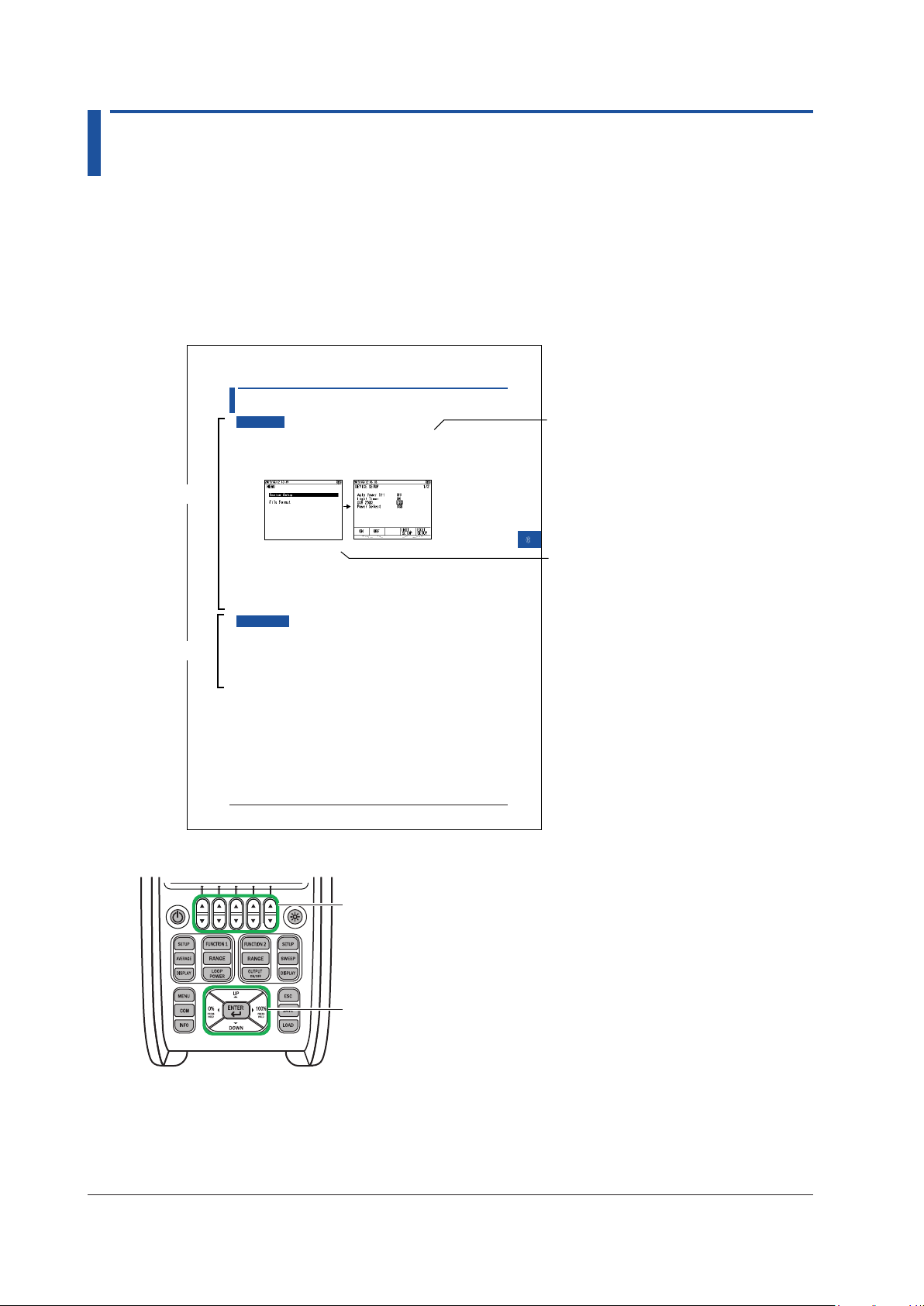
How the Procedure Is Described
In the procedure section, the panel keys and the names on the menus that are used in the steps
are indicated in bold text.
6.2 Turning Communication Resistance On or Off
Panel key
Procedure
Procedure
1.
With the source value and measurement value displayed, press MENU. A menu screen
appears.
2.
Use the cursor keys to select Device Setup, and then press ENTER. A Device Setup screen
appears.
3.
Use the cursor keys to select &20ȍ. ON and OFF appear in the selection menu.
6
Other Settings
Menu display
6-3
Explanation
4.
Use the arrow keys to select ON or OFF
Confirming the Settings
5.
Press the arrow key corresponding to EXIT SETUP. The settings are confirmed, and a screen
appears showing the source value and measurement value.
Pressing ESC causes the instrument to discard the settings and return to the menu screen.
To initialize the settings, pressing the arrow key corresponding to INIT SETUP.
Description
:KHQWKHFRPPXQLFDWLRQUHVLVWDQFHLVWXUQHGRQDȍUHVLVWRULVFRQQHFWHGWRWKH9ORRS
power output inside the instrument. The communication resistance is used to provide amplitude
to the HART communication signals or BRAIN communication signals superimposed in the
transmission line.
Set this to off when communication signals are not superimposed in the transmission line.
IM CA500-01EN
In addition, “arrow keys” and “cursor keys” indicate the following keys.
Arrow keys
Cursor keys
iv
IM CA500-01EN
Page 6

Contents
Conventions Used in This Manual ................................................................................................... iii
How to Read This Manual ................................................................................................................iv
Chapter 1 Features
1.1 System Configuration and Block Diagram ..................................................................... 1-1
1.2 Source Function ............................................................................................................. 1-2
1.3 Sweep function ............................................................................................................... 1-8
1.4 Measurement Function ................................................................................................ 1-12
1.5 Calibration Function for Field Instruments ................................................................... 1-17
1.6 Saving and Loading CA500 Data ................................................................................. 1-18
1.7 Saving and Loading CA550 Data ................................................................................. 1-20
1.8 Other Features ............................................................................................................. 1-24
Chapter 2 Source
2.1 DC Voltage Source ......................................................................................................... 2-1
2.2 DC Current Source ......................................................................................................... 2-3
2.3 Resistance Source ......................................................................................................... 2-5
2.4 Voltage Source Corresponding to TC Thermoelectromotive Force ............................... 2-7
2.5 Resistance Source Corresponding to the RTD Temperature ....................................... 2-10
2.6 Frequency and Pulse Source ....................................................................................... 2-12
2.7 Setting the 0% and 100% Values ................................................................................. 2-16
2.8 Dividing and Generating the Source Values ................................................................ 2-18
2.9 Sweep Source .............................................................................................................. 2-20
Chapter 3 Measurement
3.1 DC Voltage Measurement .............................................................................................. 3-1
3.2 DC Current Measurement .............................................................................................. 3-3
3.3 Resistance Measurement .............................................................................................. 3-5
3.4 Temperature Measurement Using Thermocouples ........................................................ 3-7
3.5 Temperature Measurement Using RTDs ...................................................................... 3-10
3.6 Frequency and Pulse Measurement ............................................................................ 3-12
3.7 Setting the 0% and 100% Values ................................................................................. 3-14
3.8 Setting the Tolerance (CA550) ..................................................................................... 3-16
3.9 Average Value Display ................................................................................................. 3-17
1
2
3
4
5
6
7
Index
Chapter 4 Calibrating Field Instruments (CA550)
4.1 Calibration Procedure .................................................................................................... 4-1
4.2 Setting Calibration Conditions ........................................................................................ 4-2
4.3 Saving Calibration Results ............................................................................................. 4-5
Chapter 5 Saving Data
5.1 Saving Data Manually .................................................................................................... 5-1
5.2 Saving Sweeps .............................................................................................................. 5-4
5.3 Loading and Deleting Saved Data ................................................................................. 5-7
5.4 Copying Saved Data to a PC (CA550) ........................................................................... 5-9
5.5 Saved Data Format (CA550) ........................................................................................ 5-10
IM CA500-01EN
v
Page 7

Contents
Chapter 6 Other Features
6.1 Auto Power-off, Turning the Light Timer On and Off, and Turning the Light On and Off 6-1
6.2 Turning Communication Resistance On or Off ............................................................... 6-3
6.3 Setting the Priority Power Supply ................................................................................... 6-4
6.4 Setting the Decimal Symbol and CSV Separator ........................................................... 6-5
6.5 Setting the Date Display Format .................................................................................... 6-6
6.6 Setting the Language ..................................................................................................... 6-7
6.7 Formatting (Initializing) the Internal Memory .................................................................. 6-8
Chapter 7 USB Function
7.1 USB Interface Features and Specifications ................................................................... 7-1
7.2 Connecting through the USB Interface .......................................................................... 7-2
7.3 List of Commands .......................................................................................................... 7-3
7.4 Commands ..................................................................................................................... 7-5
7.5 Error Codes .................................................................................................................. 7-19
7.6 Status Byte Format ...................................................................................................... 7-20
Index
vi
IM CA500-01EN
Page 8
Chapter 1 Features
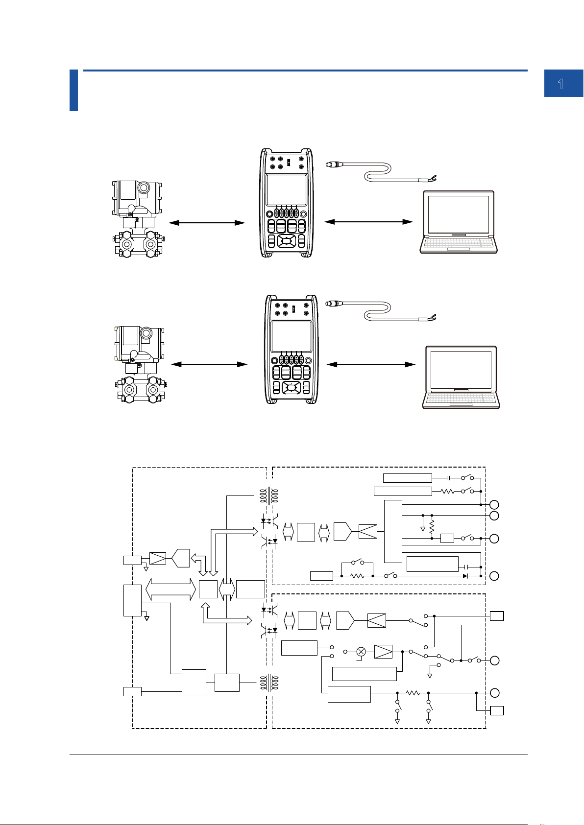
1.1 System Configuration and Block Diagram
System Configuration
RJ sensor (sold separately)
DC voltage, DC
current, resistance,
TC, RTD, pulse
CA500
DC voltage, DC
current, resistance,
TC, RTD, pulse
USB interface
(communication)
PCField instrument
RJ sensor (sold separately)
USB interface
(communication/mass
storage)
1
Features
HART/BRAIN
communication
Field instrument
Block Diagram
Power Source/Communication Port
R.J.
INPUT
USB B
BATT.
ADC
Power
source
control
CPU
DC/DC
Display
CA550
DC/DC
DC/DC
FUNCTION 1 part
CPU
DC/DC
FUNCTION 2 part
CPU
Reference
voltage source
USB interface
(HART/BRAIN modem)
Frequency counter
Constant voltage source
ADC
250Ω
ADC
DCV
DCA
Setting
OHM
Excess volatge / excess
current protection
Current voltage
conversion
OUTPUT
Power AMP
Input
circuit
Current detection
Shunt resistance
Communication
modem
TC-A
TC-A
DCVDCA
PTC
FRQ
PC
FRQ
OHM
DCA
OUTPUT
H
L
mA
+LOOP
+TC-A
H
L
-TC-A
IM CA500-01EN
1-1
Page 9
1.2 Source Function
The source function generates DC voltage, DC current, resistance, voltage corresponding to the
electromotive force of thermocouples, voltage corresponding to the resistance of RTDs (pseudo-
resistance), and pulse signals.
It can be used simultaneously with measurement functions other than temperature measurement
using thermocouples.
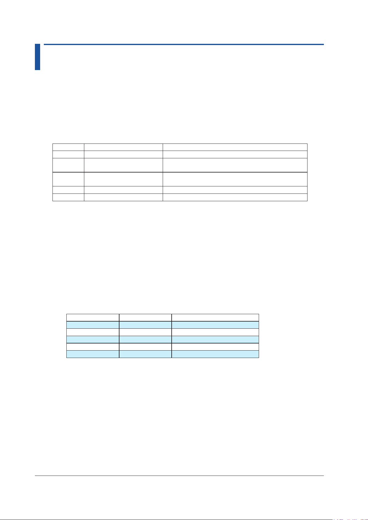
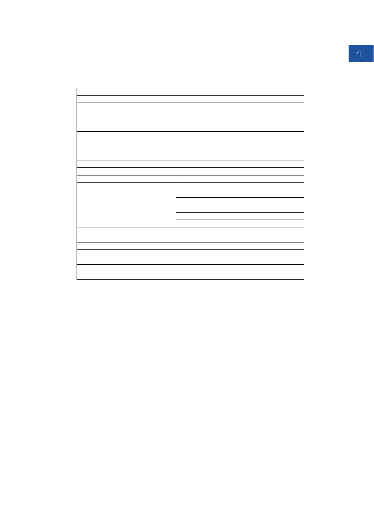
DC Voltage
This function generates the following DC voltages.
Range Source Range Notes
100 mV ±110.000 mV Maximum output current: 10 mA
1-5 V 0.0000 V to +6.0000 V Maximum output current: 10 mA
Can be used as calibration signals for 1, 2, 3, 4, 5 V.
(1-5 V√) 0.0000 V to +6.0000 V Maximum output current: 10 mA
Values for square root operation
5 V ±6.0000 V Maximum output current: 10 mA
30 V ±33.000 V Maximum output current: 1 mA
1-5 V Range
The interval between 0% and 100% is equally divided by four, and the 0%, 25%, 50%, 75%,
and 100% values are output.
With the default settings, you can change the output between 1 V, 2 V, 3 V, 4 V, and 5 V in 1
V steps by pressing the UP or DOWN key. This is convenient when calibrating the five points
from 1 to 5 V.
Square Root Output Function (1-5 V√)
Values corresponding to the square root of 0%, 25%, 50%, 75% and 100% values are
generated. You can change the output using the UP or DOWN key. This can be used as
calibration signals for the square root output of differential pressure transmitters.
Percentage and source value
Percentage 1-5 V source value Square root output (1-5V√)
0% 1.0000 V 1.0000 V
25% 2.0000 V 1.2500 V
50% 3.0000 V 2.0000 V
75% 4.0000 V 3.2500 V
100% 5.0000 V 5.0000 V
1-2
IM CA500-01EN
Page 10

1.2 Source Function
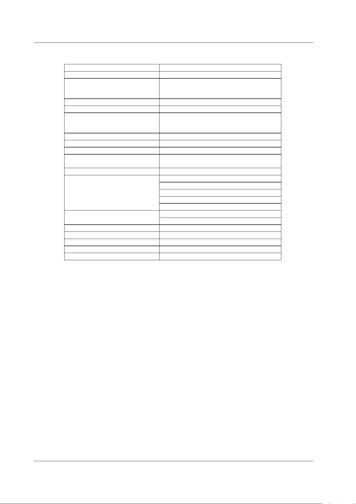
DC Current
This function generates the following DC currents.
Range Source Range Notes
20 mA ±24.000 mA Output voltage: 0 to 20 V
4-20 mA 0.000 mA to 24.00 mA Output voltage: 0 to 20 V
Can be used as calibration signals for 4, 8, 12, 16, 20 mA.
(4-20 mA√) 0.000 mA to 24.00 mA Output voltage: 0 to 20 V
Values for square root operation
4-20 mA
Simulate
4-20 mA Range
The interval between 0% and 100% is equally divided by four, and the 0%, 25%, 50%, 75%,
and 100% values are output.
With the default settings, you can change the output between 4 mA, 8 mA, 12 mA, 16 mA, and
20 mA in 4 mA steps by pressing the UP or DOWN key. This is convenient when calibrating
the five points from 4 to 20 mA.
Square Root Output Function (4-20 mA√)
Values corresponding to the square root of 0%, 25%, 50%, 75% and 100% values are
generated. You can change the output using the UP or DOWN key. This can be used as
calibration signals for the square root output of differential pressure transmitters.
Percentage and source value
Percentage 4-20 mA source value Square root output (4-20 mA√)
0% 4.000 mA 4.000 mA
25% 8.000 mA 5.000 mA
50% 12.000 mA 8.000 mA
75% 16.000 mA 13.000 mA
100% 20.000 mA 20.000 mA
0.000 mA to 24.000 mA External power supply 5 V to 28 V
1
Features
Simulate (20 mA Simulate) Function
You can connect this instrument to a distributor and simulate a two-wire transmitter. This is
valid when the range is set to 4-20 mA Simulate.
CA500/CA550
H
L
4-20mA
+
Distributor
—
IM CA500-01EN
1-3
Page 11
1.2 Source Function
Resistance
This function generates the following resistances.
Range Source Range Notes
400Ω 0.00 Ω ~ 440.00 Ω Allowable measurement current: 0.1 mA to 3 mA
4000Ω 0.0 Ω ~ 4400.0 Ω Allowable measurement current: 0.05 mA to 0.6 mA
Resistance Source Method
A pseudo-resistance (R=V/I) is sourced by generating a voltage (V=R×I) corresponding to the
resistance [R] set on the instrument across the output terminals for the current for measuring
resistance [I] supplied to the device to be calibrated such as a resistance measuring
instrument and RTD thermometer.
Therefore, this instrument can be used only for instruments that measure pseudo-resistance
using a current for measuring resistance.
How to Source Accurately
• When measuring resistance using a two-wire system, use lead cables with low resistance.
Because the source resistance is calibrated without including the voltage drop of the
leaked cables, the lead cable resistance will result in error.
• To source the resistance accurately, use of the three-wire system or four-wire system.
Calibration target
CA500/CA550
Red
Black
(three-wire
measuring instrument)
H
L
L’
1-4
IM CA500-01EN
Page 12
1.2 Source Function
Thermoelectromotive Force of a Thermocouple
Thermoelectromotive force corresponding to the following temperatures is generated for each
thermocouple type.
Thermocouple Source Range Notes
K -200.0°C to +1372.0°C IEC 60584-1
E -250.0°C to +1000.0°C IEC 60584-1
J -210.0°C to +1200.0°C IEC 60584-1
T -250.0°C to +400.0°C IEC 60584-1
N -200.0°C to +1300.0°C IEC 60584-1
L -200.0°C to +900.0°C DIN 43710
U -200.0°C to +600.0°C DIN 43710
R -20.0°C to +1767.0°C IEC 60584-1
S -20.0°C to +1768.0°C IEC 60584-1
B +600.0°C to +1820.0°C IEC 60584-1
C 0.0°C to +2315.0°C IEC 60584-1
XK -200.0°C to +800.0°C GOST R 8.585-2001
A 0.0°C to +2500.0°C IEC 60584-1
D (W3Re/W25Re) 0.0°C to +2315.0°C ASTM E1751/E1751M-09e1
G (W/W26Re) +100.0°C to +2315.0°C ASTM E1751/E1751M-09e1
PLATINEL II 0.0°C to +1395.0°C ASTM E1751/E1751M-09e1
PR20-40 0.0°C to +1888.0°C ASTM E1751/E1751M-09e1
*: Complies also with JIS C 1602
**: The setting can be changed to comply with IPTS-68 (JIS C 1602 1981).
*, **
*, **
*, **
*, **
*
*, **
*, **
*, **
*
1
Features
Temperature Scale
This instrument complies with ITS-90 and IPTS-68.
Connection Terminals
This instrument is equipped with the following two types of terminals.
TC-A (TC mini plug)
A thermocouple is connected to the instrument using a thermocouple mini plug set,
sold separately. Reference junction compensation using an external RJ sensor (sold
separately) is not possible.
TC-B (banana plug)
Reference junction compensation using the internal RJ sensor or an external RJ sensor is
possible.
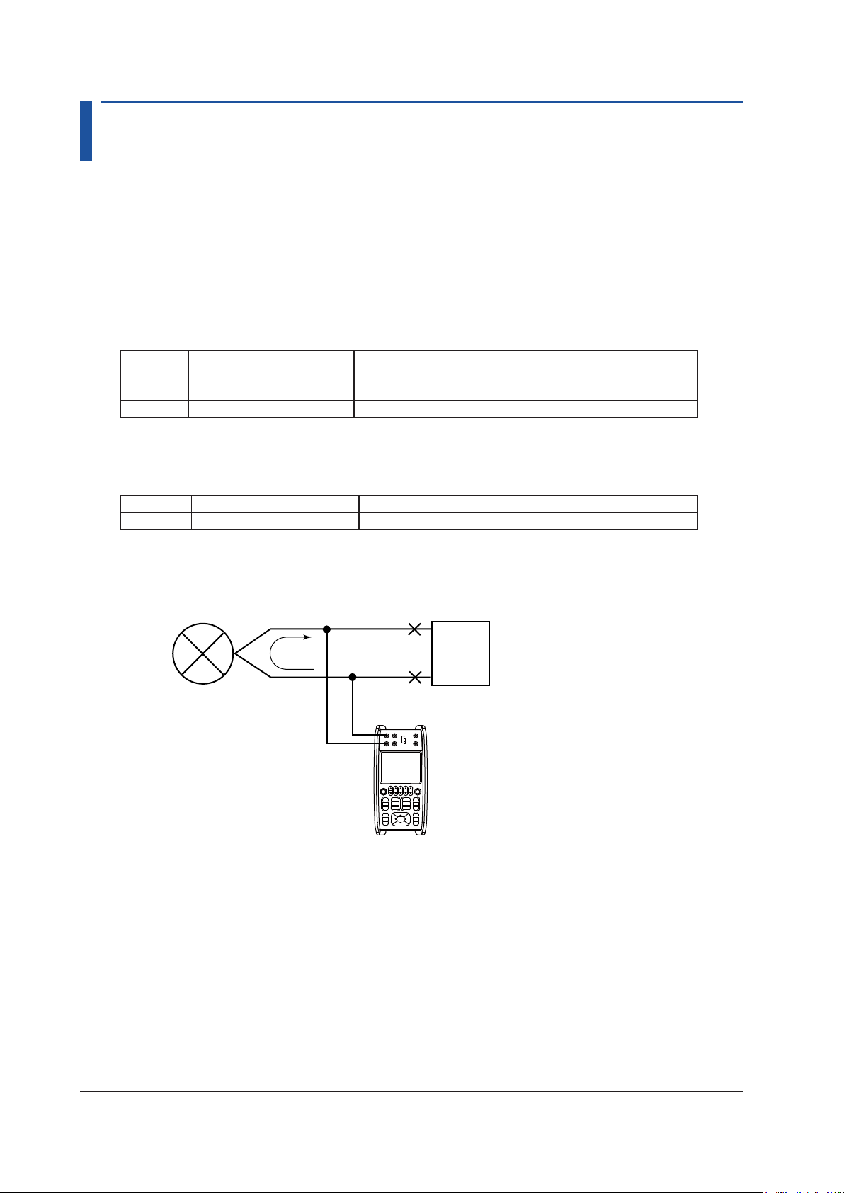
Reference Junction Compensation
The instrument measures the temperature of the contact using an RJ sensor and generates a
voltage based on the temperature component. This instrument can perform reference junction
compensation using the internal RJ sensor or an external RJ sensor.
When an instrument with a built-in reference junction temperature compensation is to be
calibrated, the reference junction temperature of the device to be calibrated is measured using
an external RJ sensor.
Calibrating only the thermometer
CA500/CA550
H
L
Calibration target
H
L
Calibrating including the thermocouple
CA500/CA550
Calibration target
H
L
H
L
H
L
H
L
IM CA500-01EN
External RJ sensor
Source/measurement
lead cable
Thermocouple
Internal RJ sensor or
external RJ sensor
Internal RJ sensor
Thermocouple
1-5
Page 13
1.2 Source Function
Resistance of an RTD
Resistance corresponding to the following temperatures is generated for each RTD type.
RTD Source Range Notes
PT100 (PT100 (3851)) -200.0°C to 800.0°C EC 60751
JPT100 (PT100 (3916)) -200.0°C to 510.0°C JIS C 1604 1989 (JPt100)
PT100 (3850) -200.0°C to 630.0°C JIS C 1604 1989 (Pt100)
PT100 (3926) -200.0°C to 630.0°C Minco Application Aid #18
PT200 -200.0°C to 630.0°C IEC 60751
PT500 -200.0°C to 630.0°C IEC 60751
PT1000 -200.0°C to 630.0°C IEC 60751
Cu10 -100.0°C to 260.0°C Minco Application Aid #18
Ni120 -80.0°C to 260.0°C Minco Application Aid #18
PT50 -200.0°C to 630.0°C IEC 60751
PT50G -200.0°C to 800.0°C GOST R 8.625-2006
PT100G -200.0°C to 630.0°C GOST R 8.625-2006
Cu50M -180.0°C to 200.0°C GOST R 8.625-2006
Cu100M -180.0°C to 200.0°C GOST R 8.625-2006
*
*
*
*
*
*: Complies also with JIS C 1604
Frequency
Pulse signals are generated at the following frequencies.
Range Source Range Notes
500 Hz 1.00 Hz to 550.00 Hz
5000 Hz 1.0 Hz to 5500.0 Hz
50 kHz 0.001 kHz to 50.000 kHz
CPM 1.0 to 1100.0/min Generates a signal with a specified number of
pulses per minute
The sweep function cannot be used.
For source range CPM, you can set the frequency using the number of pulses to generate per
minute.
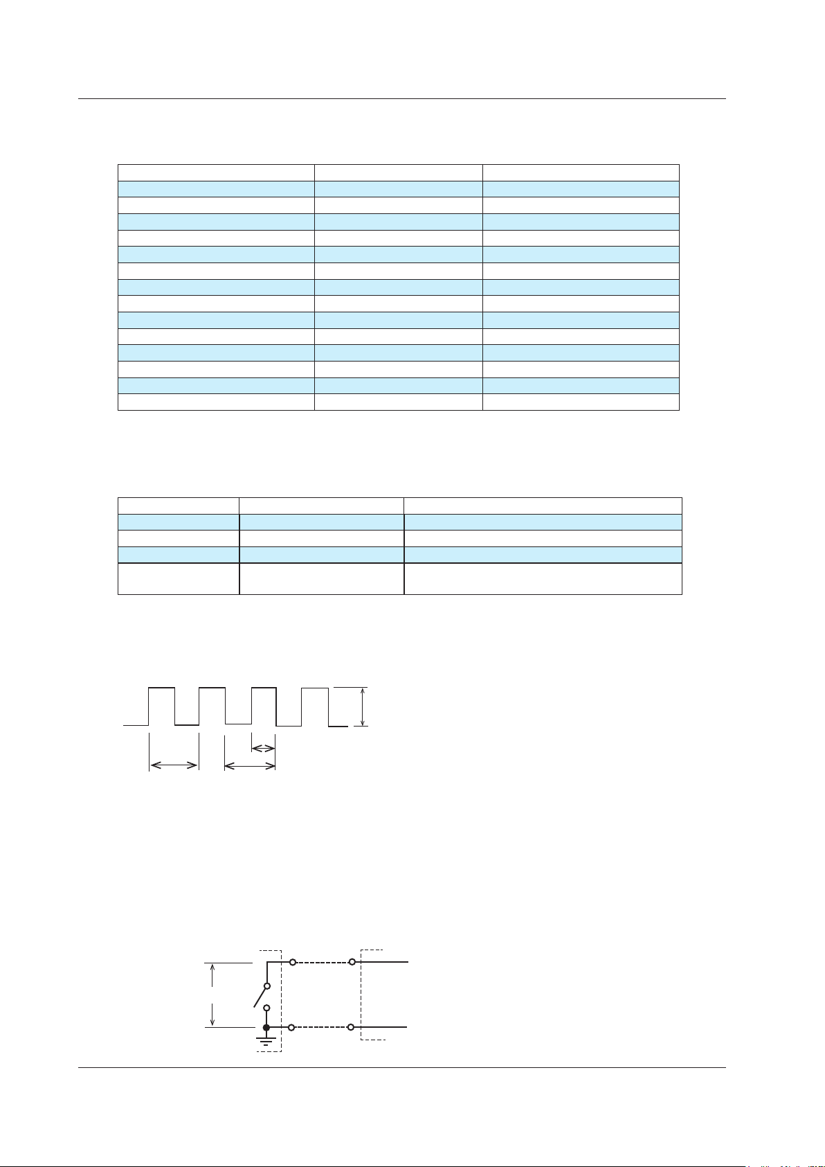
This instrument outputs waveforms at 50% duty cycle.
1-6
Amplitude
h
1 pulse
Frequency = pulse count/s, CPM = pulse count/min
Duty: (h/t)×100%
t
Contact Output
If the contact output is set on during frequency output, a contact signal can be output with the
specified frequency or number of pulses.
The instrument’s
output terminal
H
0.5 to 30 VDC
L
Input terminal of the
output destination device
H
L
IM CA500-01EN
Page 14
1.2 Source Function
0% and 100% Values
These values become references for the source values when dividing or sweeping the source
values.
When the source is to be generated in divisions, the interval between 0% and 100% is divided
equally by a specified number, and the source value is changed stepwise through key operation.
In a linear sweep, the source value is varied linearly from 0% to 100% or from 100% to 0% over a
specified time period.
In a step sweep, the interval from 0% to 100% is divided equally by a specified number, and the
source value is automatically varied stepwise.
Number of Divisions
The interval between 0% and 100% is divided equally by a specified number, and the source value
is changed stepwise by operating the cursor keys (UP and DOWN keys).
For example, if 0% is set to 50 mV, 100% is set to 100 mV, and the number division is set to 4,
each time you press UP, the source value changes as follows: 0% (50 mV), 25% (62.5 mV), 50% (75
mV), 75% (87.5 mV), 100% (100 mV).
When the source range is 1-5V, 1-5V√, 4-20mA, 4-20mA√, or 4-20mA Simulate, the number
divisions is fixed to 4.
1
Features
Display Switching
You can select the value to show on the main display of the function 2 display area between a
physical value such as a voltage or a percentage.
In the case of a temperature measurement using a thermocouple or RTD, the thermal electromotive
force or resistance can be shown in sub display 2. Moreover, in the case of a temperature
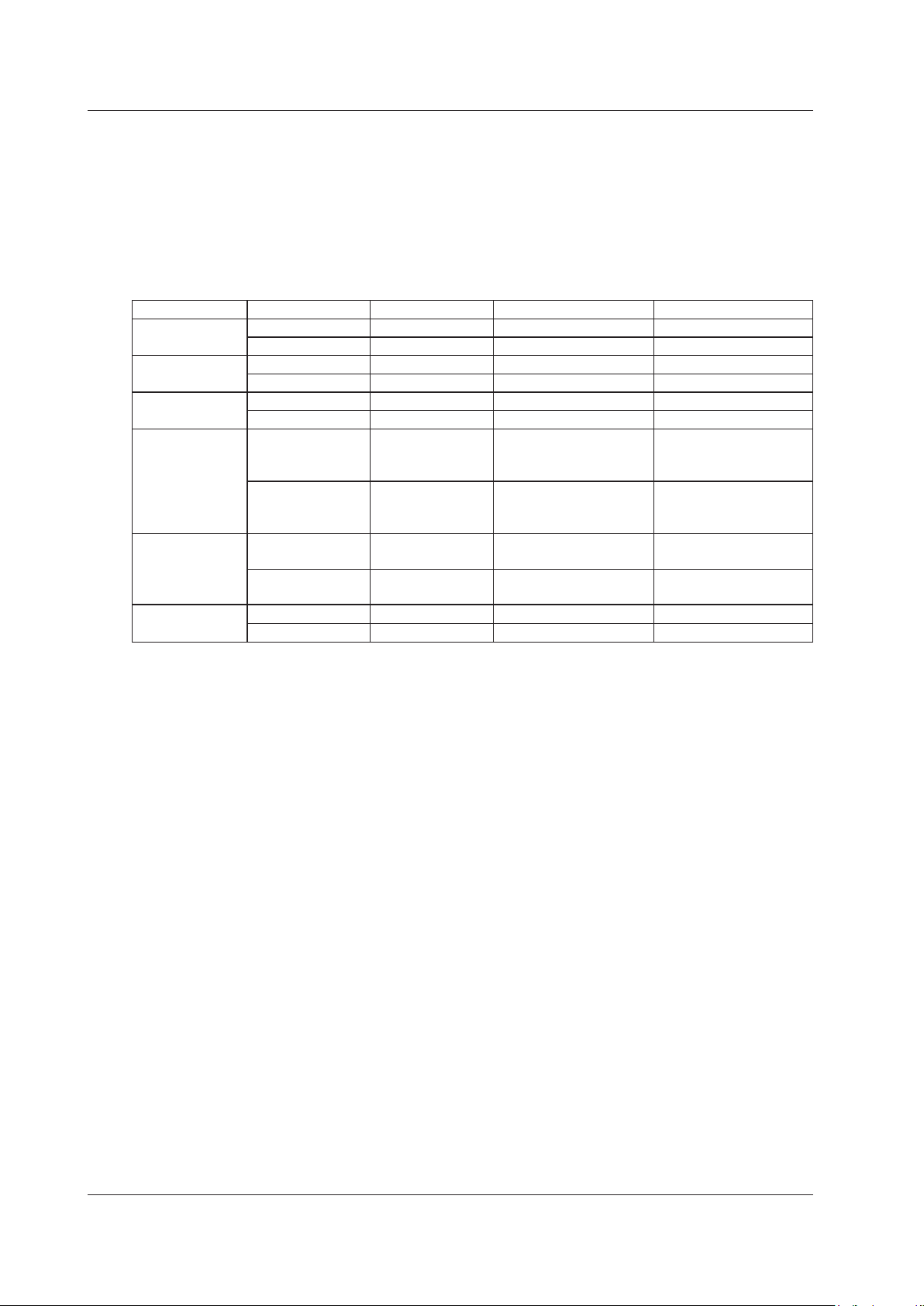
measurement using a thermocouple, the reference junction temperature can also be shown.
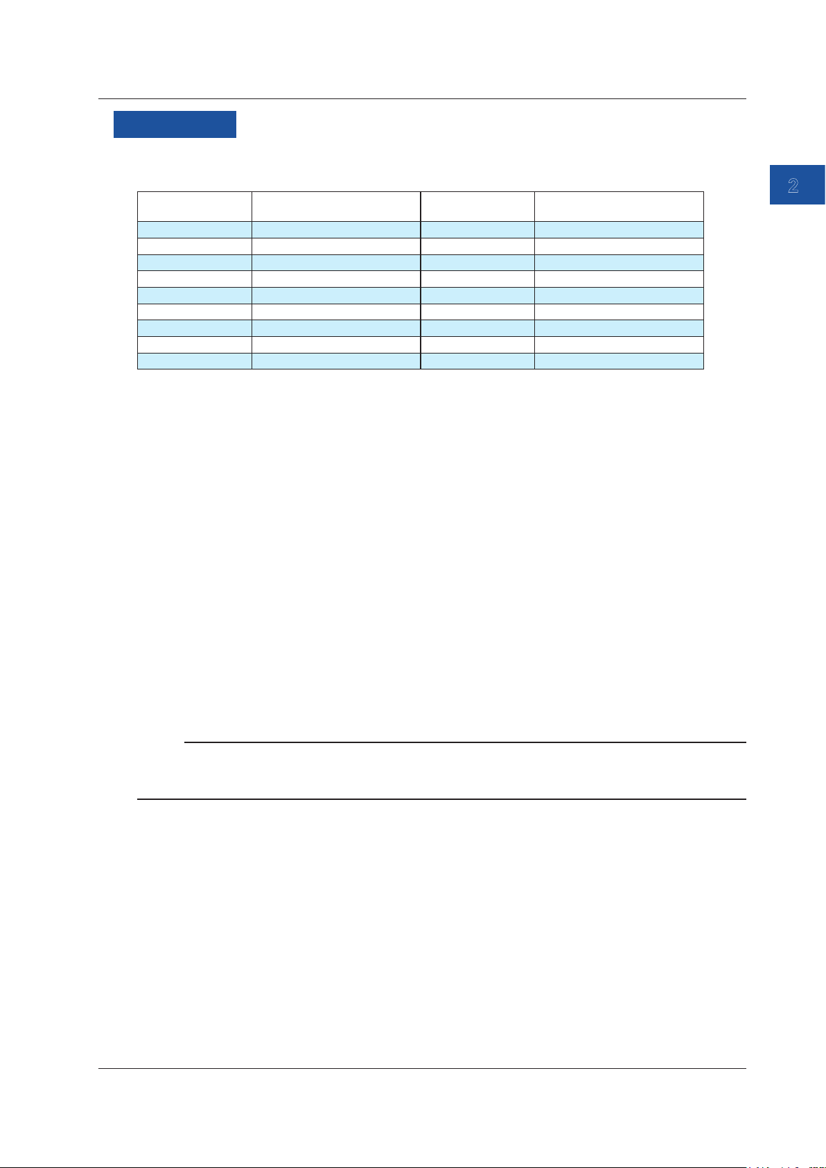
Function Main display Sub display 1 Sub display 2 Sub display 3
DC voltage Source value Percentage — —
Percentage Source value — —
DC Current Source value Percentage — —
Percentage Source value — —
Resistance Source value Percentage — —
Percentage Source value — —
Thermocouple Source value (°C) Percentage Source value(voltage) Temperature monitor
(reference junction
temperature)
Percentage Source value (°C) Source value(voltage) Temperature monitor
(reference junction
temperature)
RTD Source value (°C) Percentage Source value (resistance ) —
Percentage Source value (°C) Source value (resistance ) —
Frequency Source value Percentage — —
Percentage Source value — —
The source value or percentage shown in the main display area can also be changed directly using
arrow keys.
IM CA500-01EN
1-7
Page 15
1.3 Sweep function
The source value can be varied according to a process set in advance.
There are three types: linear sweep, step sweep, and program sweep.
This cannot be used when the source function is set the frequency.
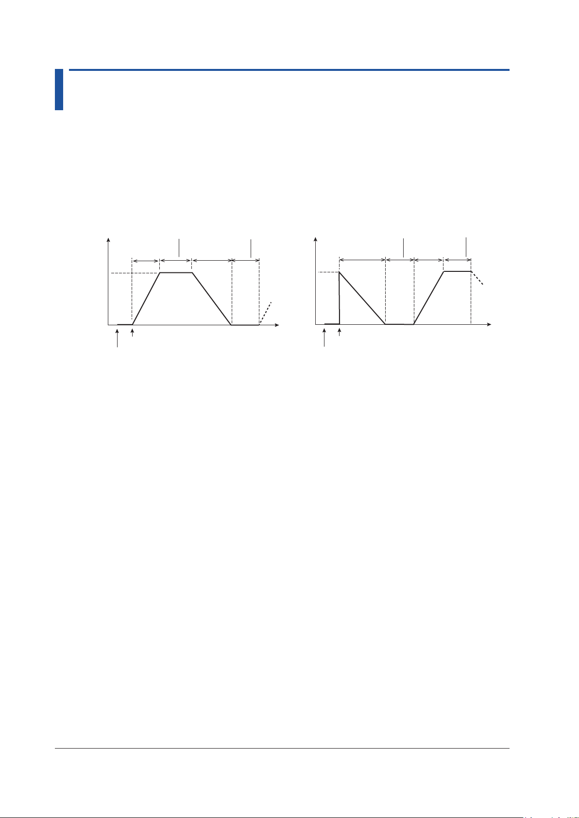
Linear Sweep
The source value is varied linearly from 0% to 100% (sweep up) or from 100% to 0% (sweep
down).
Source
value
100%
0%
Interval
Sweep time
(rise time)
Sweep start (UP key)
Output on
time
Sweep time
(fall time)
Interval
time
Source
value
Time
100%
0%
Interval
time
Sweep time
(fall time)
Sweep start (DOWN key)
Output on
Sweep time
(rise time)
Interval
time
Time
Sweep Time
The time period during which the source value is varied. You can set the rise time and fall time
separately.
Interval Time
The time period during which the source value is held when the source value reaches 0% or
100% after sweeping.
1-8
IM CA500-01EN
Page 16
Output on (OUTPUT key)
1.3 Sweep Function
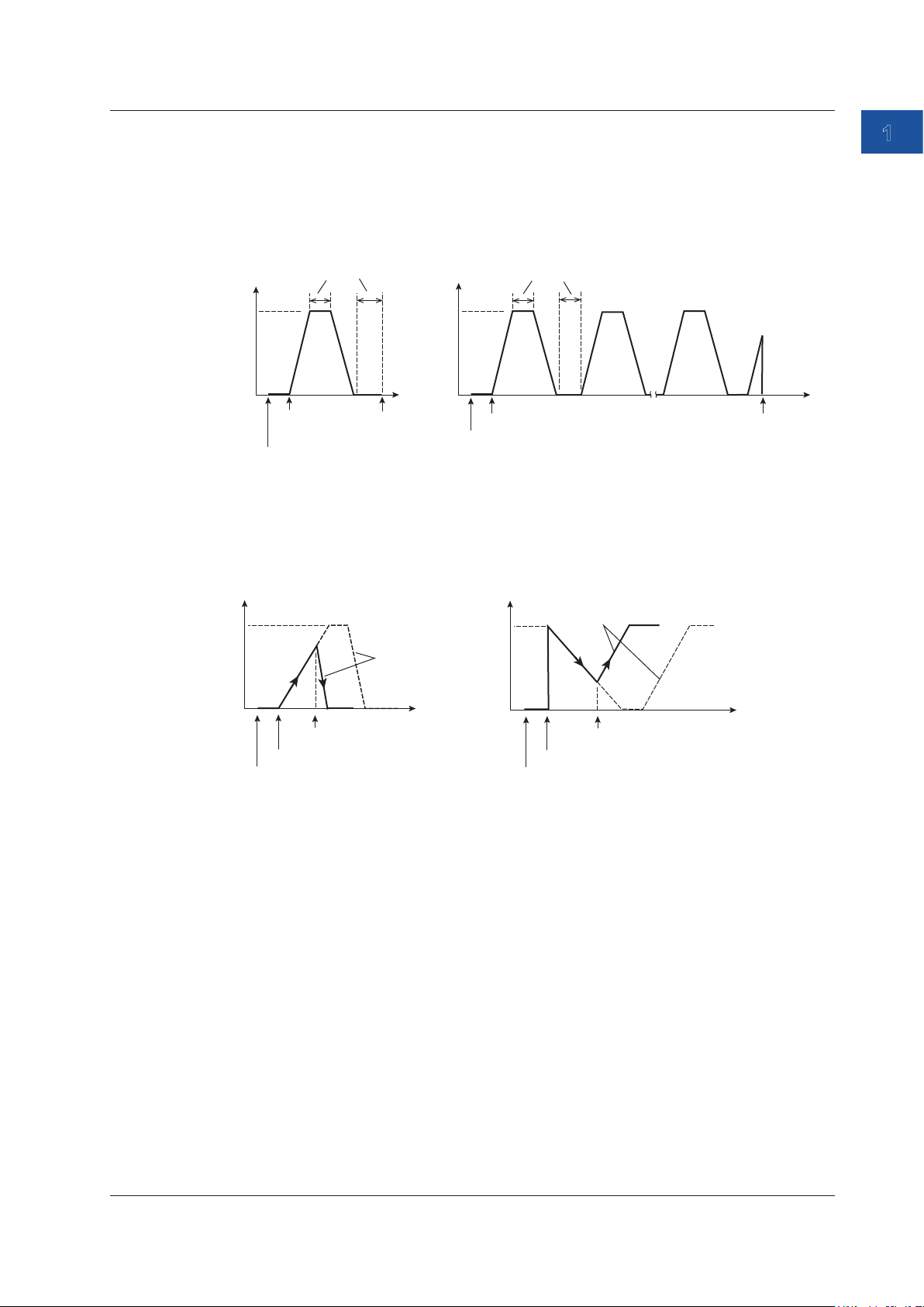
Repetition
Sweeping is repeated until the source is turned off. If sweeping is performed for one iteration,
sweeping stops automatically when the interval time elapses after sweeping.
Repetition: Off
Source
value
100%
0%
Sweep start
(UP key)
Interval
time
Repetition: On
Source
value
100%
0%
Time
Sweep stop
Interval time
Sweep start (UP key)
Output on (OUTPUT key)
Output off
(OUTPUT key)
Time
Operation While Sweeping Is in Progress
If you press UP or DOWN while sweeping is in progress (including the interval time) the suite
direction changes.
1
Features
Sweep up->Sweep down
100%
Same slope
0%
DOWN key
Sweep start (UP key)
Output on (OUTPUT key)
Sweep down->Sweep up
100%
0%
Output on (OUTPUT key)
Same slope
UP key
Sweep start
(DOWN key)
If you press OUTPUT while sweeping is in progress, the source turns off.
IM CA500-01EN
1-9
Page 17
1.3 Sweep Function
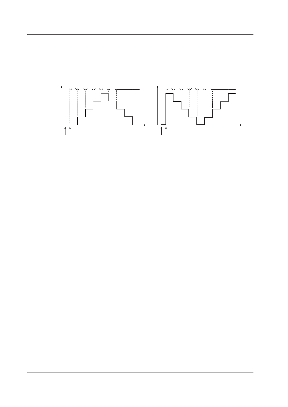
Step Sweep
The source value interval from 0% to 100% is divided equally by a specified number, and the
source value is varied stepwise.
The source time of each step is set with interval time.
Source
value
100%
0%
t
Sweep start (UP key)
Output on
t
t
t: Interval time
t
t
t
Source
t
Time
value
100%
0%
t
t
t
Sweep start (DOWN key)
Output on
t t
t
t: Interval time
t t t
t
t
Number of Divisions
The source value interval from 0% to 100% is divided by the specified number. The variation
of each step is given by
Variation = (100% source value - 0% source value)/number of divisions.
Given 0% source value = 1 V, 100% source value = 5 V, number of divisions = 4,
(5 V-1 V)/4 = 1 V.
The source value is stepped up or down by 1 V.
Interval Time
The time period during which the source value of each step is held.
Time
Repetition
Sweep up->Sweep down or Sweep down->Sweep up can be performed once to complete the
sweep, or this cycle can be repeated until the output is turned off.
Saving Data
After sweeping, source values, measure values, and other data can be saved to files.
For details, see section 1.6, “Saving and Loading CA500 Data”, or section 1.7, “Saving and
Loading CA550 Data”.
1-10
IM CA500-01EN
Page 18
1.3 Sweep Function
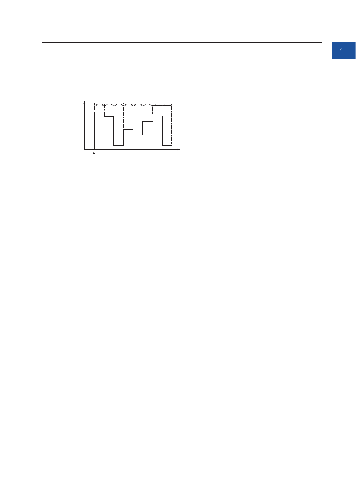
Program Sweep
The CA500 and CA550 generate up to 10 and 20 specified values, respectively, in order by
switching.
You can set source values to match specific calibration points.
2
Source
value
100%
0%
1
t
Output on
t
Interval Time
The time period during which each source value is held.
Source Number
You can assign source values to each number from 1 to 10 on the CA500 and 1 to 20 on the
CA550.
When the output is turned on, the specified source values are generated in order from source
number 1.
The source time of each source number is the interval time.
4
3
t
5
t
t
7
6
t
t
Source number
8
t
Interval time
Time
1
Features
Saving Data
After sweeping, source values, measure values, and other data can be saved to files.
For details, see section 1.6, “Saving and Loading CA500 Data”, or section 1.7, “Saving and
Loading CA550 Data”.
Calibration Target Information (CA550)
On the CA550, you can set the model number, serial number, tag number, and loop name of
the device to be calibrated and include them in the saved data.
IM CA500-01EN
1-11
Page 19
1.4 Measurement Function
The measurement function measures DC voltage, DC current, resistance, temperature, and pulse
signals.
It can be used simultaneously with source functions other than temperature measurement using
thermocouples.
Temperature measurement using thermocouples can be performed simultaneously with another
measurement.
DC voltage
This function measures the following DC voltages.
Range Measurement Range Notes
100 mV ±110.000 mV Input resistance: 1 GΩ or more
5 V ±6.0000 V Input resistance: Approx.1 MΩ
50 V ±55.000 V Input resistance: Approx.1 MΩ
DC Current
This function measures the following DC currents.
Range Measurement Range Notes
50 mA ±60.000 mA Input resistance: 10 Ω or less
Loop Power
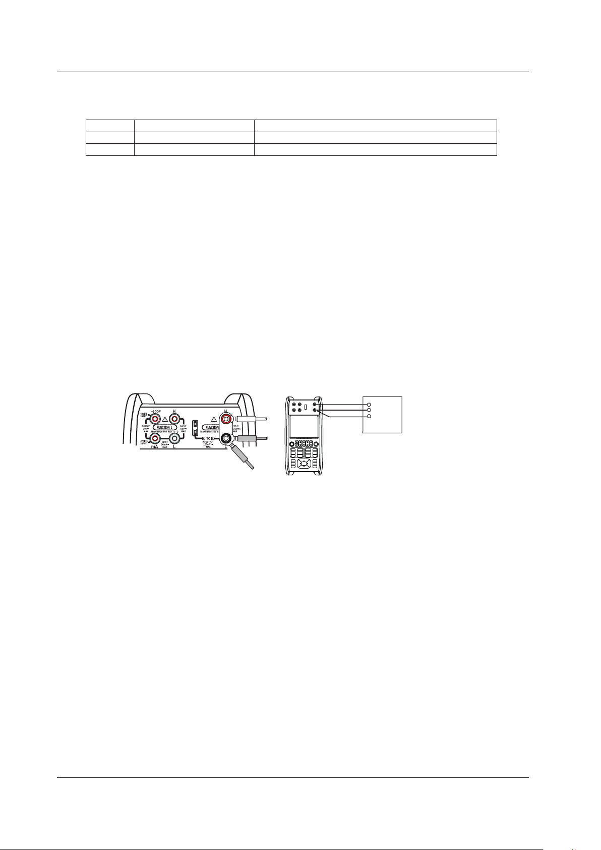
A loop test can be performed by applying a constant voltage of 24 VDC to a two-wire
transmitter and measuring the transfer signal.
—
H
L
Distributor
+
Two-wire transmitter
4-20mA
24VDC
CA500/CA550
1-12
IM CA500-01EN
Page 20
1.4 Measurement Function
Resistance
This function measures the following resistances.
Range Measurement Range Notes
400Ω 0.00 Ω ~ 440.00 Ω
4000Ω 0.0 Ω ~ 4400.0 Ω
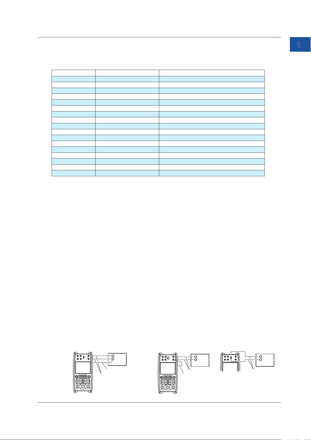
Wiring Systems
The following wiring systems are available: two-wire, three-wire, and four-wire.
Two-wire system: Because measurements include the resistance of measurement lead
cables and contact resistance, errors become large. Use this when the
resistance of the DUT is sufficiently larger then the resistance of the
measurement lead cables and contact resistance.
Three-wire system: By making the length of the three measurement lead cables the same,
measurements can be made without hardly being affected by the
resistance of the lead cables.
Four-wire system: Measurements can be made by eliminating the resistance of measurement
lead cables and contact resistance. Use this when you want to make
accurate measurements.
Voltage applied current measurement method
Typical values: 1 mA@0 Ω, 781 μA@400 Ω, 240 μA@4 kΩ
1
Features
Temperature Measurement Using Thermocouples
Temperature is measured using the following thermocouples.
Thermocouple Measurement Range Notes
K -200.0°C to +1372.0°C IEC 60584-1
E -250.0°C to +1000.0°C IEC 60584-1
J -210.0°C to +1200.0°C IEC 60584-1
T -250.0°C to +400.0°C IEC 60584-1
N -200.0°C to +1300.0°C IEC 60584-1
L -200.0°C to +900.0°C DIN 43710
U -200.0°C to +600.0°C DIN 43710
R -20.0°C to +1767.0°C IEC 60584-1
S -20.0°C to +1768.0°C IEC 60584-1
B +600.0°C to +1820.0°C IEC 60584-1
C 0.0°C to +2315.0°C IEC 60584-1
XK -200.0°C to +800.0°C GOST R 8.585-2001
A 0.0°C to +2500.0°C IEC 60584-1
D (W3Re/W25Re) 0.0°C to +2315.0°C ASTM E1751/E1751M
G (W/W26Re) +100.0°C to +2315.0°C ASTM E1751/E1751M
PLATINEL II 0.0°C to +1395.0°C ASTM E1751/E1751M
PR20-40 0.0°C to +1888.0°C ASTM E1751/E1751M
*: Complies also with JIS C 1602
**: The setting can be changed to comply with IPTS-68 (JIS C 1602 1981).
Temperature Scale
This instrument complies with ITS-90 and IPTS-68.
*, **
*, **
*, **
*, **
*
*, **
*, **
*, **
*
IM CA500-01EN
1-13
Page 21
1.4 Measurement Function
Connection Terminals
This instrument is equipped with the following two types of terminals.
TC-A terminal (TC mini plug)
A thermocouple is connected to the instrument using a thermocouple mini plug set, sold
separately. Reference junction compensation using an external RJ sensor (sold separately) is
not possible.
TC-B terminal (banana plug)
Reference junction compensation using the internal RJ sensor or an external RJ sensor is
possible.
Reference Junction Compensation
The instrument measures the temperature of the reference contact using an RJ sensor and
makes measurements based on that temperature.
This instrument can perform reference junction compensation using the internal temperature
sensor or an external RJ sensor.
When using the TC-A mini plug terminal, you cannot use an external RJ sensor.
Burnout
Thermocouple burnout is detected. When a burnout is detected, this instrument displays “B
OUT” on the screen.
Temperature Measurement Using RTDs
Temperature is measured using the following RTDs.
RTD Measurement range Notes
PT100 (PT100 (3851)) -200.0°C to 800.0°C EC 60751
JPT100 (PT100 (3916)) -200.0°C to 510.0°C JIS C 1604 1989 (JPt100)
PT100 (3850) -200.0°C to 630.0°C JIS C 1604 1989 (Pt100)
PT100 (3926) -200.0°C to 630.0°C Minco Application Aid #18
PT200 -200.0°C to 630.0°C IEC 60751
PT500 -200.0°C to 630.0°C IEC 60751
PT1000 -200.0°C to 630.0°C IEC 60751
Cu10 -100.0°C to 260.0°C Minco Application Aid #18
Ni120 -80.0°C to 260.0°C Minco Application Aid #18
PT50 -200.0°C to 630.0°C IEC 60751
PT50G -200.0°C to 800.0°C GOST R 8.625-2006
PT100G -200.0°C to 630.0°C GOST R 8.625-2006
Cu50M -180.0°C to 200.0°C GOST R 8.625-2006
Cu100M -180.0°C to 200.0°C GOST R 8.625-2006
*: Complies also with JIS C 1604
Wiring Systems
The following RTD wiring systems are available: two-wire, three-wire, and four-wire.
Two-wire system: Because the resistance in the lead wires connecting the RTD and the
instrument is included in the measurement, errors become large. Use this when
the RTD and the instrument are close.
Three-wire system: By making the length of the three measurement lead wires connecting the
RTD and the instrument the same, measurements can be made without hardly
being affected by the resistance of the lead cables.
Four-wire system: Measurements can be made without being affected by the resistance in
the lead wires connecting the RTD and the instrument.
1-14
*
*
*
*
*
IM CA500-01EN
Page 22
1.4 Measurement Function
Frequency
This function measures the following frequencies.
Range Measurement range Notes
500 Hz 1.00 Hz to 550.0 Hz
5000 Hz 1.0 Hz to 5500.0 Hz
50 kHz 0.001 kHz to 50.000 kHz
Pulse count 0 to 99999 The number of pulses is counted within a unit
time period.
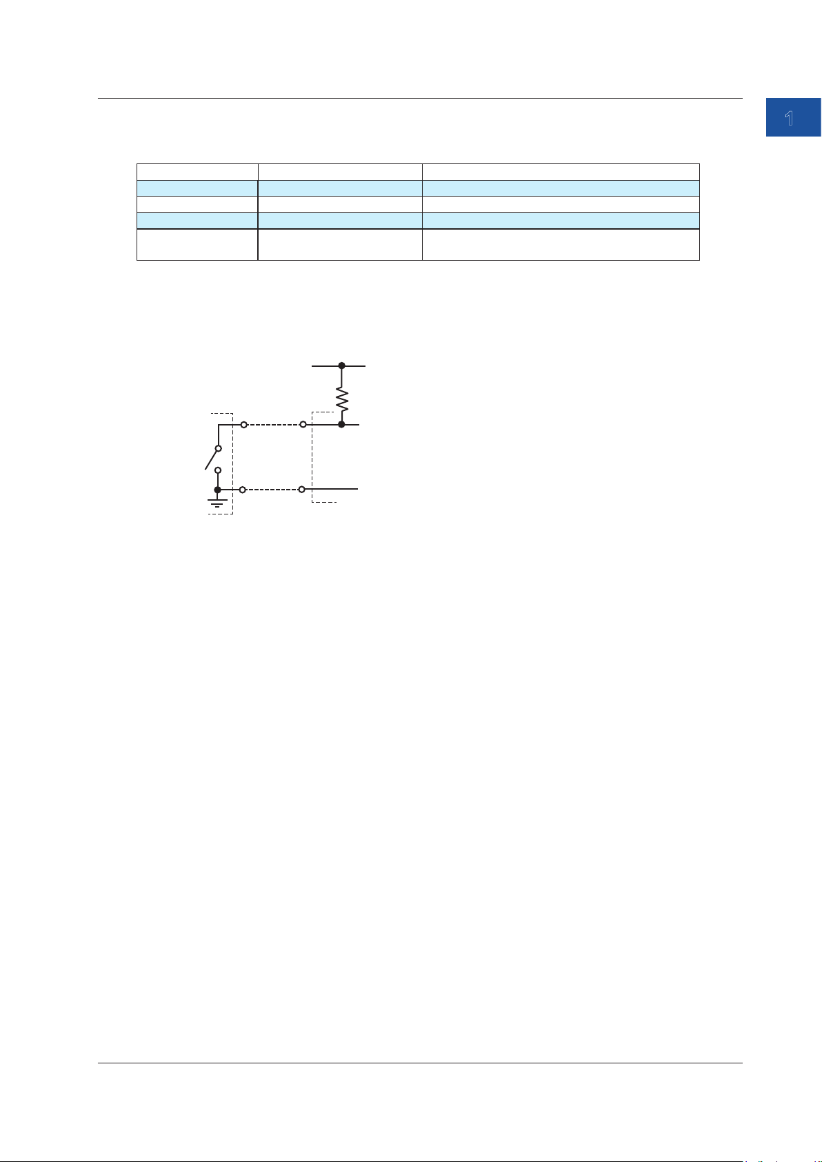
Contact Input
The frequency or the number of signals per minute can be measured through a contact input
using a non-voltage contact.
Vcc (approx. 5 V)
H
L
H
L
Approx. 100 kΩ
1
Features
Measurement
signal
The instrument’s
input terminal
Averaging
Moving average values for every five measured values and the maximum value (MAX) and
minimum value (MIN) of the moving average values are displayed on the screen.
0% and 100% Values
By mapping the output value (specified according to the specifications of the device to be
calibrated) to the 0% or 100% source value of this instrument, you can determine the output value
of the device to be calibrated for the source value.
For example, if the source value of 0% is 1 V and that of 100% is 5 V and the output values are
4 mA and 20 mA when 1 V and 5 V are input to the device be calibrated, assign 4 mA to the
measured value of 0% and 20 mA to that of 100%.
In this situation, the output value (specified according to the specifications of the device to be
calibrated) is 8 mA for a source value of 2 V of this instrument.
4 mA + (20 mA - 4 mA)×(2 V - 1 V)/(5 V - 1 V) = 8 mA
The CA550 calculates the error in the actual output value relative to the output value (specified
according to the specifications of the device to be calibrated) that is mapped to the source value.
Furthermore, this instrument calculates the measurement value percentages relative to the
specified 0% value and 100% value.
IM CA500-01EN
1-15
Page 23
1.4 Measurement Function
Display Switching
You can select the value to show on the main display of the function 1 display area (function 2
display area for temperature measurements using a thermocouple) between a physical value such
as a voltage or a percentage.
In the case of a temperature measurement using a thermocouple or RTD, the thermal electromotive
force or resistance can be shown in sub display 2. Moreover, in the case of a temperature
measurement using a thermocouple, the reference junction temperature can also be shown.
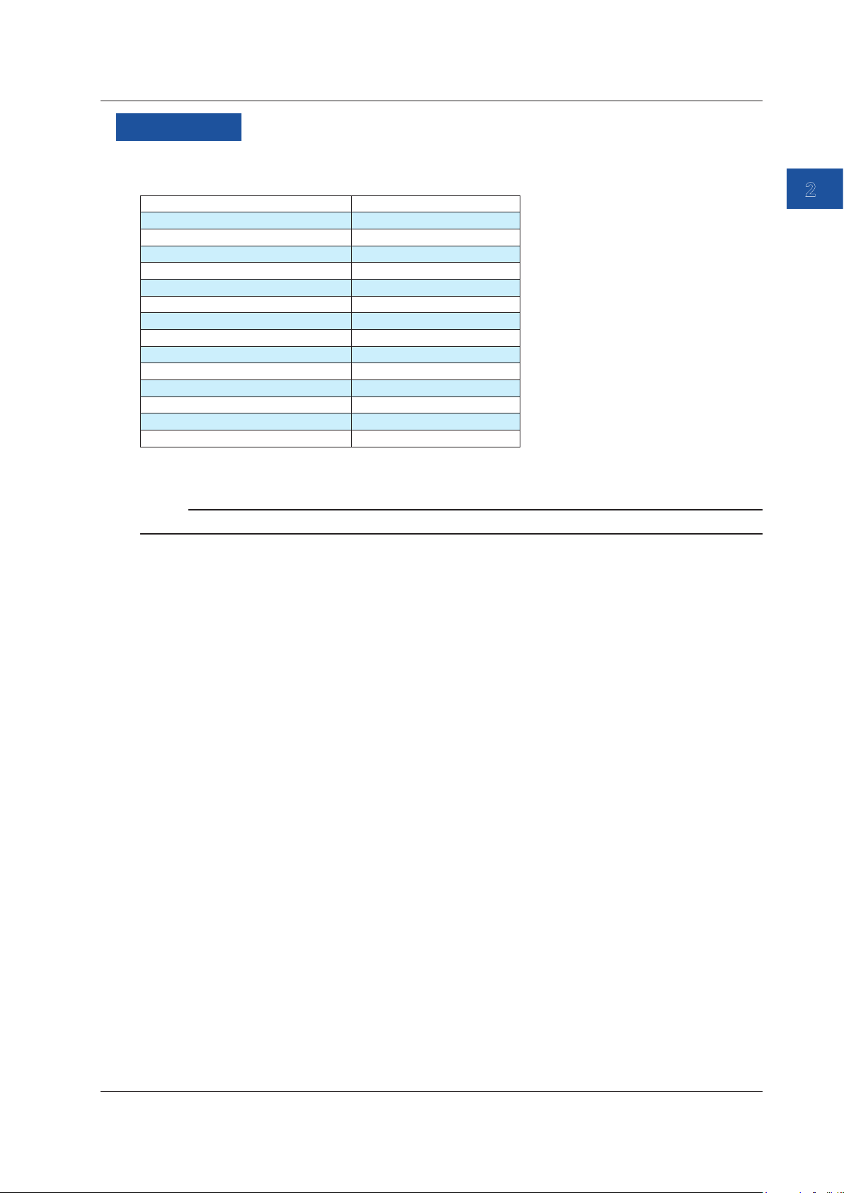
Function Main display Sub display 1 Sub display 2 Sub display 3
DC voltage Measured value Percentage — —
Percentage Measured value — —
DC Current Measured value Percentage — —
Percentage Measured value — —
Resistance Measured value Percentage — —
Percentage Measured value — —
Thermocouple Measured value
(°C)
Percentage Measured value
RTD Measured value
(°C)
Percentage Measured value
Frequency Measured value Percentage — —
Percentage Measured value — —
Percentage Measured value (voltage) Temperature monitor
(reference junction
temperature)
Measured value (voltage) Temperature monitor
(°C)
Percentage Measured value
(resistance)
Measured value
(°C)
(resistance)
(reference junction
temperature)
—
—
1-16
IM CA500-01EN
Page 24

1.5 Calibration Function for Field Instruments
The following functions are available to efficiently calibrate field instruments.
1-5V Range
DC voltages from 1 to 5 V, which are common instrumentation signals, are generated in 1 V steps.
This is useful when calibrating the five input signals: 1 V, 2 V, 3 V, 4 V, and 5 V.
4-20 mA Range
DC currents from 4 to 20 mA, which are common instrumentation signals, are generated in 4 mA
steps.
This is useful when calibrating the five input signals: 4 mA, 8 mA, 12 mA, 16 mA, and 20 mA.
Program Sweep (CA550)
By using the CA550 program sweep function, you can assign instrument information such as the
calibration target model number, serial number, and tag number. The assigned information can be
saved as CSV data along with source values, measured values, and errors.
Because measured values, source values, errors, pass/fail judgment results, and the like can be
saved to a file automatically after a program sweep is completed, this is useful for recording data
before adjustment or data after adjustment.
1
Features
Errors and Pass/Fail Judgment (CA550)
The instrument determines the error in the actual output value of the device to be calibrated relative
to the output value (specified according to the specifications of the device to be calibrated) that is
mapped to the source value.
Moreover, the instrument indicates pass or fail depending on whether the measured value is within
the tolerance set in advance.
You can view the errors and pass/fail judgments in the files saved automatically by the program
sweep function.
IM CA500-01EN
1-17
Page 25
1.6 Saving and Loading CA500 Data
For details on the CA550, see section 1.7.
Saving Data
The following three methods are available to save data.
• Save data by pressing the SAVE key
• Save data automatically after the completion of a step sweep
• Save data automatically after the completion of a program sweep
A total of 100 data entries (memory numbers 1 to 100) can be saved using the above three
methods.
Saving Data Using the SAVE Key
The date and time, information such as the specified function and range, and the measured
value and source value when the SAVE key is pressed are saved.
Auto Save in Step Sweeps or Program Sweeps
The date and time, information such as the specified function and range, the source value and
measured value of each sweep step, and sweep conditions are saved.
Data is saved in a dedicated format of this instrument. Data can be transmitted to a PC using
communication commands.
Memory Number
Saved data is automatically assigned a memory number from 01 to 100.
This also applies when data is saved automatically in a step sweep or program sweep. The data of
each step is assigned a memory number.
Saved Information
The following information is saved.
Function1 Information
Saved data Notes
Measured value
Function
Range
0% value
100% value
Contact input setting
Count time
1-18
IM CA500-01EN
Page 26

1.6 Saving and Loading CA500 Data
Function2 Information
Saved Data Notes
Source value
Function
Range
0% value
100% value
Sweep setting* Interval time
Repeat
Saving Data ON/OFF
Temperature
setting
Frequency setting Amplitude voltage setting
TC measurement
settings
Contact output setting ON/OFF
Thermocouple terminal TC-A/TC-B
TC-B RJC setting ON/OFF
Burnout setting ON/OFF
TC scale standard setting IPTS-68/ITS-90
Temperature unit °C
Pulse count setting
0% value
100% value
* Not saved when using the SAVE key.
Loading Data
Specify the memory number containing the saved data to load the information. The instrument
settings are changed to the loaded settings.
Measured value and source value are shown in the Function1 and Function2 display positions.
1
Features
IM CA500-01EN
1-19
Page 27

1.7 Saving and Loading CA550 Data
For details on the CA500, see section 1.6.
Saving Data
The following three methods are available to save data.
• Save data by pressing the SAVE key
• Save data automatically after the completion of a step sweep
• Save data automatically after the completion of a program sweep
Saving Data Using the SAVE Key
Information such as the specified function and range, and the date and time, measured value,
and source value when the SAVE key is pressed are saved. Each time you press SAVE, the
measurement data is added to the same file. However, a new file is created in the following
cases.
• When a setting is changed on the Device Setup screen
• When the function or range is changed
• When the number of save data points exceeds 2000
• When the power is turned off
Auto Save in Step Sweeps
Information such as the specified function and range, the date and time, source value, and
measured value at the completion of each sweep step, and sweep conditions are saved.
Auto Save in Program Sweeps
Calibration target information, information such as the specified function and range, the date
and time, source value, and measured value at the completion of each sweep step, and
sweep conditions are saved as calibration data of field instruments.
The data format is CSV. You can select a comma, semicolon, or tab for the data separator.
In addition, you can select the measured value to be saved, the decimal symbol of the source
value, and the date and time format.
1-20
IM CA500-01EN
Page 28
1.7 Saving and Loading CA550 Data
Saved Information
The following information is saved.
Saving Data Using the SAVE Key
Saved Data Notes
MODEL CA550
FILE TYPE 0: Manually saved data using the SAVE key
1: Automatically saved data by a step sweep
2: Calibration data by a program sweep
CSV SEPARATOR 0: Comma, 1: Semicolon, 2: Tab
DECIMAL POINT 0: Period, 1: Comma
DATE FORMAT 0: YYYY/MM/DD
1: DD/MM/YYYY
2: MM/DD/YYYY
Range Measurement range, source range
0% VALUE
100% VALUE
CONTACT (contact I/O) 0: OFF, 1:ON
TC SETTING
(temperature setting)
FREQUENCY SETTING
(frequency setting)
No. Number
DATE Measurement date YYYY/MM/DD
TIME Measurement time hh:mm:ss
MEASURE Measured value
SOURCE Source value
Thermocouple terminal setting. 0: TC-A, 1: TC-B
TC-B RJC setting. 0: OFF, 1:ON
Burnout setting. 0: OFF, 1:ON
TC scale standard setting. 0: ITS-90, 1:IPTS-68
Temperature unit. 0: °C
Amplitude voltage setting
Pulse count setting
1
Features
IM CA500-01EN
1-21
Page 29
1.7 Saving and Loading CA550 Data
Saving Data Using Step Sweep
Saved data Notes
MODEL CA550
FILE TYPE 0: Manually saved data using the SAVE key
CSV SEPARATOR 0: Comma, 1: Semicolon, 2: Tab
DECIMAL POINT 0: Period, 1: Comma
DATE FORMAT 0: YYYY/MM/DD
Range Measurement range, source range
0% VALUE
100% VALUE
DIVISION NUMBER (number of
divisions)
CONTACT (contact I/O) 0: OFF, 1:ON
TC SETTING
(temperature setting)
FREQUENCY SETTING
(frequency setting)
No. Number
DATE Measurement date YYYY/MM/DD
TIME Measurement time hh:mm:ss
MEASURE Measured value
SOURCE Source value
1: Automatically saved data by a step sweep
2: Calibration data by a program sweep
1: DD/MM/YYYY
2: MM/DD/YYYY
Thermocouple terminal setting. 0: TC-A, 1: TC-B
TC-B RJC setting. 0: OFF, 1:ON
Burnout setting. 0: OFF, 1:ON
TC scale standard setting. 0: ITS-90, 1:IPTS-68
Temperature unit. 0: °C
Amplitude voltage setting
Pulse count setting
1-22
IM CA500-01EN
Page 30
1.7 Saving and Loading CA550 Data
Saving Data Using Program Sweep
Saved data Notes
MODEL CA550
FILE TYPE 0: Manually saved data using the SAVE key
1: Automatically saved data by a step sweep
2: Calibration data by a program sweep
CSV SEPARATOR 0: Comma, 1: Semicolon, 2: Tab
DECIMAL POINT 0: Period, 1: Comma
DATE FORMAT 0: YYYY/MM/DD
1: DD/MM/YYYY
2: MM/DD/YYYY
Range Measurement range, source range
0% VALUE
100% VALUE
CONTACT (contact I/O) 0: OFF, 1:ON
TC SETTING
(temperature setting)
FREQUENCY SETTING
(frequency setting)
MODEL NO. Model number
TAG NO. Tag number
SERIAL NO. Serial number
CALIBRATION DATE Calibration date
CALIBRATOR S/N CA550 serial number
No. Calibration point number
DATE Calibration date YYYY/MM/DD
TIME Calibration time of the calibration point hh:mm:ss
MEASURE Measured value
SOURCE Source value
ERROR% Error
PASS/FAIL Pass/fail
Thermocouple terminal setting. 0: TC-A, 1: TC-B
TC-B RJC setting. 0: OFF, 1:ON
Burnout setting. 0: OFF, 1:ON
TC scale standard setting. 0: ITS-90, 1:IPTS-68
Temperature unit. 0: °C
Amplitude voltage setting
Pulse count setting
YYYY/MM/DD
1
Features
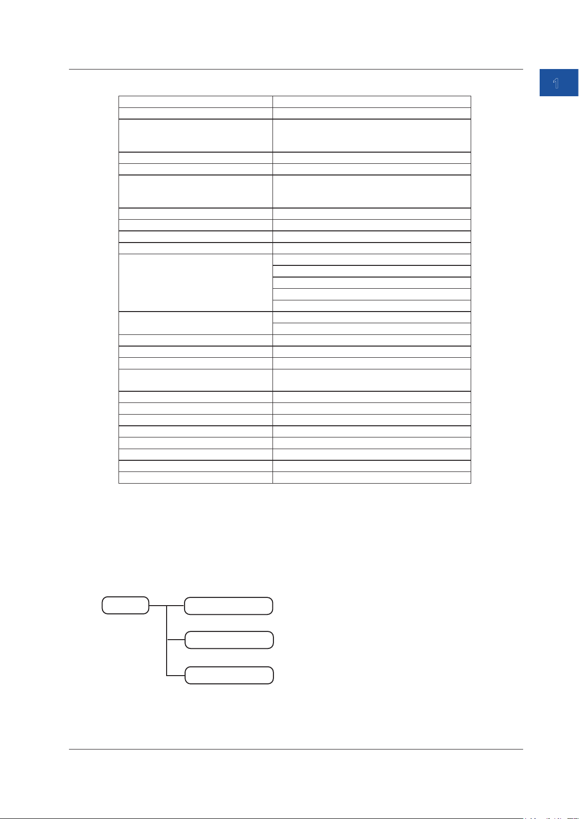
Loading Data
Only the data saved using program sweep can be loaded.
Folder Structure
The following figure shows the CA550 folder structure.
Data saved with the SAVE key is saved.
Measurement/source data (.csv) of step
sweeps is saved.
Measurement/source data (.csv) of program
sweeps is saved.
IM CA500-01EN
Root
SaveData
SweepData
CalibrationData
1-23
Page 31

1.8 Other Features
Communication Function
You can connect the instrument to a PC through the USB port. You can remotely control the
instrument from a PC or use the instrument as a USB device on the PC.
Remote Control
You can use dedicated communication commands to remotely control the instrument from a
PC. The following operations can be controlled remotely.
• CA500/CA550 configuration (limited features)
• CA500/CA550 configuration retrieval (limited features)
• Measured data retrieval
USB Mass Storage (CA550)
You can use the instrument as a PC’s USB mass storage device.
From a PC, you can access the instrument’s internal memory and read the data.
Data cannot be written to the instrument’s internal memory from a PC.
Auto Power-off
When the auto power-off feature is enabled, the instrument automatically turns off if there is no user
interaction for about 30 minutes. Auto power-off is automatically disabled (the icon also disappears)
in the following situations.
• Pulse count is in progress.
• The output is on.
• Sweeping is in progress.
• Power is being supplied through USB.
Turning the Screen Light On and Off
To reduce battery consumption, you can turn off the screen light or adjust the brightness between
two levels.
Further, the screen light can be turned off automatically when there is no user interaction with the
instrument for a given period.
Note
If the screen light is turned on in a dark location, white spots may appear on the screen.
This is due to the material characteristics of the light guide of the screen and has no effect on the
performance of the instrument.
Communication Resistance
This instrument has an built-in 250 Ω communication resistor. When communicating with a
transmitter, you do not need to prepare a separate external resistor.
Power Supply Priority
When both batteries and USB power supply are available, priority can be given to either source.
When the priority power supply cannot be used, a switch is made to the other part supply.
1-24
IM CA500-01EN
Page 32

1.8 Other Features
CSV Separator
The CSV separator can be set to a comma, semicolon, or tab.
Decimal Point
The decimal point can be set to a period or comma.
Date Display Format
You can select the date display format from the following:
YYYY/MM/DD
DD/MM/YYYY
MM/DD/YYYY
YYYY: year (Gregorian), MM: month, DD: day
The format is applied to the date and time displayed in the upper left of the screen, the date and
time on the LOAD screen, and the date and time saved in CSV files from the CA550.
Language
You can select the language used on the screen from the following:
English, Japanese, Chinese, Korean, Russian
1
Features
Formatting the Internal Memory
You can format the internal memory.
The format type is quick format (logical format).
Instrument Information
You can view the model (CA500/CA550), serial number, firmware version, and most recent
inspection date or calibration date.
A simple wiring diagram is displayed according to the Function 1 and Function 2 settings.
IM CA500-01EN
1-25
Page 33
Chapter 2 Source
1
2.1 DC Voltage Source
Procedure
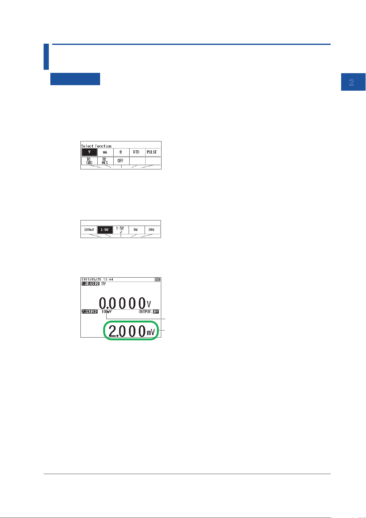
Setting the Function
1.
With the source value and measurement value displayed, press FUNCTION 2. The function
options are displayed.
2.
Use the arrow keys to select V. The display returns to the source and measurement value
display.
Setting the Source Range
3.
Under Function 2, press RANGE.
4.
Use the arrow keys to set the source range. The display returns to the source and measurement
value display.
Setting the Source Value
2
Source
5.
With the source value and measurement value displayed, use the arrow keys to set the source
value.
Source range
Source value
When the source range is 1-5V or 1-5V√, pressing UP or DOWN changes the source value at a
given interval.
Turning the Source On and Off
6.
With the source value and measurement value displayed, press OUTPUT ON/OFF.
The displayed voltage is generated. OUTPUT:OFF on the screen changes to OUTPUT:ON.
To turn off the source, press OUTPUT ON/OFF again.
7.
When the source range is 1-5V or 1-5V√, press UP or DOWN to change the source value.
Divided Source
See section 2.8, “Dividing and Generating the Source Values”.
Sourcing with the Sweep Function
See section 2.9, “Sweep Source”.
IM CA500-01EN
2-1
Page 34

2.1 DC Voltage Source
Description
Source Range
You can select from the following five source ranges.
Range Source Range
100 mV ±110.000 mV
1-5 V 0.0000 V to +6.0000 V
1-5 V√ 0.0000 V to +6.0000 V
Values for square root operation
5 V ±6.0000 V
30 V ±33.000 V
1-5V
The interval between 0% and 100% is equally divided by four, and the 0%, 25%, 50%,
75%, and 100% values are output. By default, because the 0% value is assigned to 1.0000
V and the 100% value is assigned to 5.0000 V, this can be used as a calibration signal for
instruments that use 1 to 5 V as input signals.
Square Root Commendation Function (1-5V√)
This can be used as a calibration signal for instruments that output the square root of input
signals.
Values for square root operation are generated.
Source Value
Voltages within each source range are generated.
In the default setting of the 1-5V range, 1 V to 5 V are divided into four, and 1 V, 2 V, 3 V, 4 V, and 5
V are generated.
In the default setting of the 1-5V√ range, 1 V to 5 V are divided into four, and values corresponding
to the square root of 1 V, 2 V, 3 V, 4 V, and 5 V are generated.
Source value = (%/100)×(%/100)×(100% value - 0% value) + 0%
In the default setting of the 1-5V√ range, 0% = 1 V and 100% = 5 V, so for 25% = 2 V,
Source value = (25/100)×(25/100)×(5 V - 1 V) + 1 V = 1.25 V.
Notes about Sourcing
Be careful not to short the output terminals.
When the output terminals are shorted, the output is automatically turned off by the protection
function.
2-2
IM CA500-01EN
Page 35
1
2.2 DC Current Source
Procedure
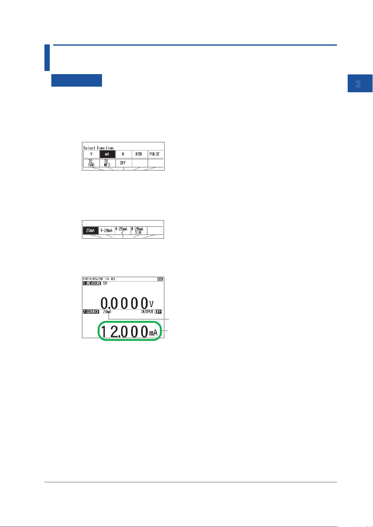
Setting the Function
1.
With the source value and measurement value displayed, press FUNCTION 2. The function
options are displayed.
2.
Use the arrow keys to select mA. The display returns to the source and measurement value
display.
Setting the Source Range
3.
Under Function 2, press RANGE.
4.
Use the arrow keys to set the source range. The display returns to the source and measurement
value display.
Setting the Source Value
5.
With the source value and measurement value displayed, use the arrow keys to set the source
value.
2
Source
Source range
Source value
When the source range is 4-20mA, 4-20mA√ or 4-20mA Simulate, pressing UP or DOWN
changes the source value at a given interval.
Turning the Source On and Off
6.
With the source value and measurement value displayed, press OUTPUT ON/OFF.
The source value set in step five is output, and OUTPUT:OFF on the screen changes to
OUTPUT:ON.
To turn off the source, press OUTPUT ON/OFF again.
7.
When the source range is 4-20mA, 4-20mA√ or 4-20mA Simulate, press UP or DOWN to
change the source value.
Divided Source
See section 2.8, “Dividing and Generating the Source Values”.
Sourcing with the Sweep Function
See section 2.9, “Sweep Source”.
IM CA500-01EN
2-3
Page 36

2.2 DC Current Source
Description
Source Range
You can select from the following four source ranges.
Range Source Range
20 mA ±24.000 mA
4-20 mA 0.000 mA to 24.000 mA
4-20 mA√ 0.000 mA to 24.000 mA
4-20 mA Sim 0.000 mA to 24.000 mA
4-20mA
The interval between 0% and 100% is equally divided by four, and the 0%, 25%, 50%, 75%,
and 100% values are output. By default, because the 0% value is assigned to 4.000 mA
and the 100% value is assigned to 20.000 mA, this can be used as a calibration signal for
instruments that use 4 to 20 mA as input signals.
Square Root Computation Function (4-20 mA√)
This can be used as a calibration signal for instruments that output the square root of input
signals.
DC currents corresponding to the square root of 4 mA, 8 mA, 12 mA, 16 mA, and 20 mA are
generated.
4-20 mA Simulate
Currents ranging from 0 to 20 mA that simulate transfer signals are generated. This can be
used to perform a loop check on the source value by connecting to a distributor or the like.
CA500/CA550
H
L
4-20mA
+
Distributor
—
Output 1 to 5 V
Source Value
Currents within each source range are generated.
In the default setting of the 4-20mA and 4-20mA Simulate ranges, 4 mA to 20 mA are divided into
four, and 4 mA, 8 mA, 12 mA, 16 mA, and 20 mA are generated.
In the default setting of the 4-20mA√ range, 4 mA to 20 mA are divided into four, and values
corresponding to the square root of 4 mA, 8 mA, 12 mA, 16 mA, and 20 mA are generated.
Source value = (%/100)×(%/100)×(100% value - 0% value) + 0% value
In the 4-20mA√ range, 0% = 4 mA and 100% = 20 mA, so for 25% = 8 mA,
Source value = (25/100)×(25/100)×(20 mA - 4 mA) + 4 mA = 5 mA.
Notes about Sourcing
Be careful not to open the output terminals.
When the output terminals are opened, the output is automatically turned off by the protection
function.
2-4
IM CA500-01EN
Page 37

1
2.3 Resistance Source
Procedure
Setting the Function
1.
With the source value and measurement value displayed, press FUNCTION 2. The function
options are displayed.
2.
Use the arrow keys to select Ω. The display returns to the source and measurement value
display.
Setting the Source Range
3.
Under Function 2, press RANGE.
4.
Use the arrow keys to set the source range. The display returns to the source and measurement
value display.
Setting the Source Value
2
Source
5.
With the source value and measurement value displayed, use the arrow keys to set the source
value.
Source range
Source value
Turning the Source On and Off
6.
With the source value and measurement value displayed, press OUTPUT ON/OFF.
The source value set in step five is output, and OUTPUT:OFF on the screen changes to
OUTPUT:ON.
To turn off the source, press OUTPUT ON/OFF again.
Divided Source
See section 2.8, “Dividing and Generating the Source Values”.
Sourcing with the Sweep Function
See section 2.9, “Sweep Source”.
IM CA500-01EN
2-5
Page 38

2.3 Resistance Source
Description
Source Range
You can select from the following two source ranges.
Range Source Range
400 Ω 0.00 Ω ~ 440.00 Ω
4000 Ω 0.0 Ω ~ 4400.0 Ω
Note
If the allowable measurement current exceeds the upper limit, the source value display blinks.
2-6
IM CA500-01EN
Page 39
1
2.4 Voltage Source Corresponding to TC Thermoelectromotive Force
Procedure
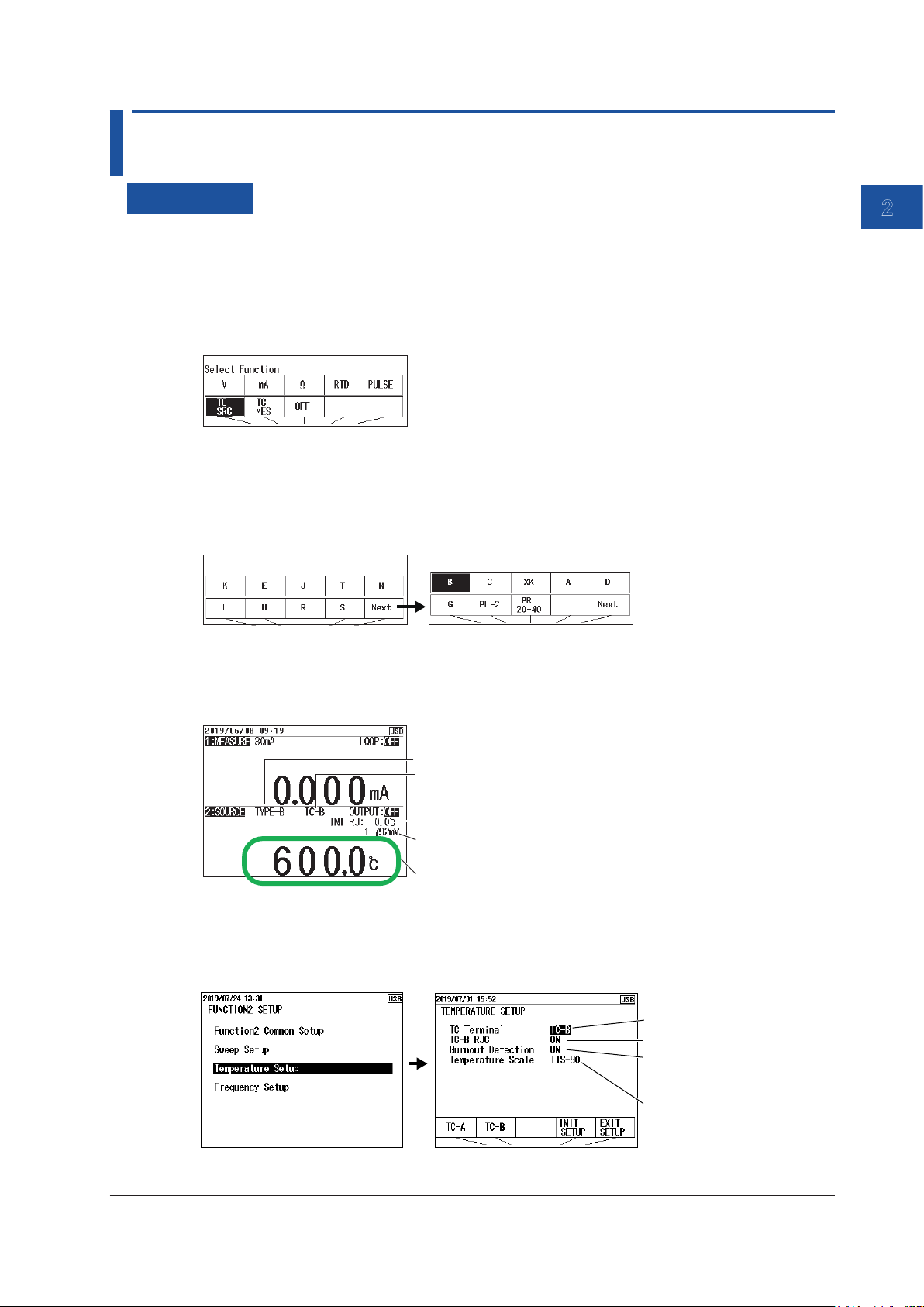
Setting the Function
1.
With the source value and measurement value displayed, press FUNCTION 2. The function
options are displayed.
2.
Use the arrow keys to select TC SRC (source). The display returns to the source and
measurement value display.
Setting the Source Range (TC Type)
3.
Under Function 2, press RANGE.
4.
Use the arrow keys to set the TC type. The display returns to the source and measurement
value display.
2
Source
Setting the Source Value
5.
With the source value and measurement value displayed, use the arrow keys to set the source
value.
Source range
Terminal to use
Reference junction temperature
Thermoelectromotive force corresponding
to the set temperature
Source value
Selecting the Terminal
6.
With the source value and measurement value displayed, press SETUP under Function 2.
7.
Select Temperature Setup, and press ENTER. A Temperature Setup setup screen appears.
Set the terminal.
Set the RJC sensor.
Turn burnout on or off.
(measurement setting
see section 3.4)
Set the temperature
scale.
8.
Select TC Terminal. TC-A and TC-B appear in the selection menu.
IM CA500-01EN
2-7
Page 40

2.4 Voltage Source Corresponding to TC Thermoelectromotive Force
9.
Using the arrow keys, select TC-A to use the TC-A terminal (thermocouple mini plug) or TC-B
to use TC-B.
To finish entering the settings here, proceed to step 14.
Setting the Reference Junction Compensation (RJC) (when using the TC-B
terminal)
10.
Select TC-B RJC. ON and OFF appear in the selection menu.
11.
Use the arrow keys to set RJC to ON or OFF.
To finish entering the settings here, proceed to step 14.
Setting the Temperature Scale
12.
Select Temperature Scale. Options appear in the selection menu.
13.
Use the arrow keys to set the temperature scale.
Confirming the Settings
14.
Press the arrow key corresponding to EXIT SETUP. The settings are confirmed, and a screen
appears showing the source value and measurement value.
The cancel the settings, press ESC to return to the screen in step 6.
To initialize the settings, pressing the arrow key corresponding to INIT SETUP.
Turning the Source On and Off
15.
With the source value and measurement value displayed, press OUTPUT ON/OFF.
The source value set in step five is output, and OUTPUT:OFF on the screen changes to
OUTPUT:ON.
To turn off the source, press OUTPUT ON/OFF again.
Divided Source
See section 2.8, “Dividing and Generating the Source Values”.
Sourcing with the Sweep Function
See section 2.9, “Sweep Source”.
2-8
IM CA500-01EN
Page 41
2.4 Voltage Source Corresponding to TC Thermoelectromotive Force
1
Description
Source Range (TC Type)
You can select from the following 17 TC types.
TC type
(thermocouple)
K -200.0°C to +1372.0°C B +600.0°C to +1820.0°C
E -250.0°C to +1000.0°C C 0.0°C to +2315.0°C
J -210.0°C to +1200.0°C XK -200.0°C to +800.0°C
T -250.0°C to +400.0°C A 0.0°C to +2500.0°C
N -200.0°C to +1300.0°C D (W3Re/W25Re) 0.0°C to +2315.0°C
L -200.0°C to +900.0°C G (W/W26Re) +100.0°C to +2315.0°C
U -200.0°C to +600.0°C PLATINEL II 0.0°C to +1395.0°C
R -20.0°C to +1767.0°C PR20-40 0.0°C to +1888.0°C
S -20.0°C to +1768.0°C - -
Match the TC type of this instrument to that of the measuring instrument.
Source range TC type
(thermocouple)
Source range
Output Terminal
Set whether to use the TC-A terminal (dedicated thermocouple mini plug) or TC-B terminal (banana
terminal).
If you select TC-A terminal, you cannot use an external RJ sensor (sold separately).
When using the TC-B terminal, we recommend that you use the included binding post (99045).
2
Source
Turning Reference Junction Compensation (RJC) On and Off
When using the TC-B terminal, set whether to perform RJC (ON/OFF).
ON: If an external RJ sensor is connected, the external RJ sensor is used to perform
reference junction compensation.
If an external RJ sensor is not connected, the internal RJ sensor is used to perform
reference junction compensation.
OFF: Reference junction compensation is not performed.
When the TC-A terminal is used, the internal RJ sensor is always used to perform reference
junction compensation.
Note
• The internal RJ sensor measures the temperature of the instrument’s terminal.
• When the temperature inside the instrument is high, wait for the temperature to decrease before use.
• For the external RJ sensor, use the 90080 RJ sensor, sold separately.
Temperature Scale
TC types K, E, J, T, R, S, and B can also handle the IPTS-68 temperature scale..
IPTS-68: The international temperature scale standard of 1968
ITS-90: The international temperature scale standard of 1990
Notes about Sourcing
If you perform a temperature measurement or temperature source using an RJC immediately after
using loop power or simulating 20 mA, the measured value or source value may be affected by the
temperature rise inside the instrument. Wait for the temperature inside instrument to stabilize before
using it.
IM CA500-01EN
2-9
Page 42

2.5 Resistance Source Corresponding to the RTD Temperature
Procedure
Setting the Function
1.
With the source value and measurement value displayed, press FUNCTION 2. The function
options are displayed.
2.
Use the arrow keys to select RTD. The display returns to the source and measurement value
display.
Setting the Source Range (RTD Type)
3.
Under Function 2, press RANGE.
4.
Use the arrow keys to set the RTD type. The display returns to the source and measurement
value display.
Setting the Source Value
5.
With the source value and measurement value displayed, use the arrow keys to set the source
value.
RTD type
Source value
Turning the Source On and Off
6.
With the source value and measurement value displayed, press OUTPUT ON/OFF.
The source value set in step five is output, and OUTPUT:OFF on the screen changes to
OUTPUT:ON.
To turn off the source, press OUTPUT ON/OFF again.
Divided Source
See section 2.8, “Dividing and Generating the Source Values”.
Sourcing with the Sweep Function
See section 2.9, “Sweep Source”.
2-10
IM CA500-01EN
Page 43
2.5 Resistance Source Corresponding to the RTD Temperature
1
Description
Source Range (RTD Type)
You can select from the following 14 RTD types.
RTD Measurement range
PT100 (PT100 JIS (3851)) -200.0°C to 800.0°C
JPT100 (PT100 former JIS (3916)) -200.0°C to 510.0°C
PT100 (3850) -200.0°C to 630.0°C
PT100 (3926) -200.0°C to 630.0°C
PT200 -200.0°C to 630.0°C
PT500 -200.0°C to 630.0°C
PT1000 -200.0°C to 630.0°C
Cu10 -100.0°C to 260.0°C
Ni120 -80.0°C to 260.0°C
PT50 -200.0°C to 630.0°C
PT50G -200.0°C to 800.0°C
PT100G -200.0°C to 630.0°C
Cu50M -180.0°C to 200.0°C
Cu100M -180.0°C to 200.0°C
Match the RTD type of this instrument to that of the measuring instrument.
2
Source
Note
If the excitation current exceeds the upper limit, the source value display blinks.
IM CA500-01EN
2-11
Page 44

2.6 Frequency and Pulse Source
Procedure
Setting the Function
1.
With the source value and measurement value displayed, press FUNCTION 2. The function
options are displayed.
2.
Use the arrow keys to select PULSE. The display returns to the source and measurement value
display.
Setting the Source Range
3.
Under Function 2, press RANGE.
4.
Use the arrow keys to set the source range. The display returns to the source and measurement
value display.
Setting the Source Value
5.
With the source value and measurement value displayed, use the arrow keys to set the source
value.
Source range
Source value
2-12
IM CA500-01EN
Page 45

2.6 Frequency and Pulse Source
1
Setting the Pulse Signal Amplitude
6.
With the source value and measurement value displayed, press SETUP under Function 2.
7.
Select Frequency Setup, and press ENTER. A Frequency Setup setup screen appears.
Set the amplitude.
Set the pulse count.
8.
Select Amplitude Voltage, and press ENTER. The settings are displayed at the bottom of the
screen.
9.
Use the arrow keys to select the amplitude, and then press ENTER.
To finish entering the settings here, proceed to step 12.
Setting the Number of Pulses to Source
10.
Select Pulse Count, and press ENTER. The settings are displayed at the bottom of the screen.
2
Source
11.
Use the arrow keys to select the number of pulses to source, and then press ENTER.
If you set the number to 0, Continue will be selected.
Setting the Amplitude and the Number of Pulses
12.
Press the arrow key corresponding to EXIT SETUP. The settings are confirmed, and the screen
reverts to show the source value and measurement value.
The cancel the settings, press ESC to return to the screen and step 6.
To initialize the settings, pressing the arrow key corresponding to INIT SETUP.
Turning the Contact Output On and Off
13.
With the source value and measurement value displayed, press SETUP under Function 2.
14.
Select Frequency Setup, and press ENTER. A Frequency Setup setup screen appears.
Turn the contact
output on or off.
15.
Select Contact Output. ON and OFF appear in the selection menu.
16.
Use the arrow keys to set the contact output to ON or OFF. To generate contact signals, select
ON.
IM CA500-01EN
2-13
Page 46

2.6 Frequency and Pulse Source
Confirming the Contact Output
17.
Press the arrow key corresponding to EXIT SETUP. The settings are confirmed, and the screen
reverts to show the source value and measurement value.
The cancel the settings, press ESC to return to the screen and step 14.
To initialize the settings, pressing the arrow key corresponding to INIT SETUP.
Turning the Source On and Off
18.
With the source value and measurement value displayed, press OUTPUT ON/OFF.
The source value set in step 5 is output. The signal is generated according to the specified
pulse count.
To turn off the source, press OUTPUT ON/OFF again.
Divided Source
See section 2.8, “Dividing and Generating the Source Values”.
2-14
IM CA500-01EN
Page 47

Description
1
Source Range
You can select from the following four source ranges.
Range Source Range
500 Hz 1.00 Hz to 550.00 Hz
5000 Hz 1.0 Hz to 5500.0 Hz
50 kHz 0.001 kHz to 50.000 kHz
CPM 1.0 to 1100.0/min
If you select CPM, set the number of pulses to generate per minute.
Bandwidth
Set the voltage of the high side of the pulse signal. The low side is 0 V.
Set the voltage in the range of 0.1 V to 15.0 V.
The default setting is 0.1 V.
Duty Cycle
The duty cycle of the pulse signals that this instrument generates is 50%.
2.6 Frequency and Pulse Source
2
Source
Pulse Count
Set the number of pulses to generate.
If you set the number to 0, the instrument continuously generates pulse signals at the specify
frequency.
Contact Output
If you turn on the contact output, the non-voltage contact is turned on then off at the specify
frequency or the number of pulses/min.
Be careful not to apply a voltage exceeding 30 VDC to the source terminal of this instrument.
The instrument’s
output terminal
H
0.5 to 30 VDC
L
When you turn on the contact output, the amplitude setting is ignored.
Input terminal of the
output destination device
H
L
IM CA500-01EN
2-15
Page 48
2.7 Setting the 0% and 100% Values
Procedure
Setting Values Using the 0% and 100% Keys
1.
With the source value and measurement value displayed, use the arrow keys to set the 0%
source value.
2.
Hold down the 0% cursor key. The specified source value is assigned to the 0% value.
3.
Use the arrow keys to set the 100% source value.
4.
Hold down the 100% cursor key. The specified source value is assigned to the 100% value.
When you display the percentage value,
you can check the 0% or 100% values.
When you hold down the 0% or 100% key,
this value is assigned to 0% or 100%.
Note
If you display the percentage on the screen using the DISPLAY key, you can view the assigned 0% and
100% values.
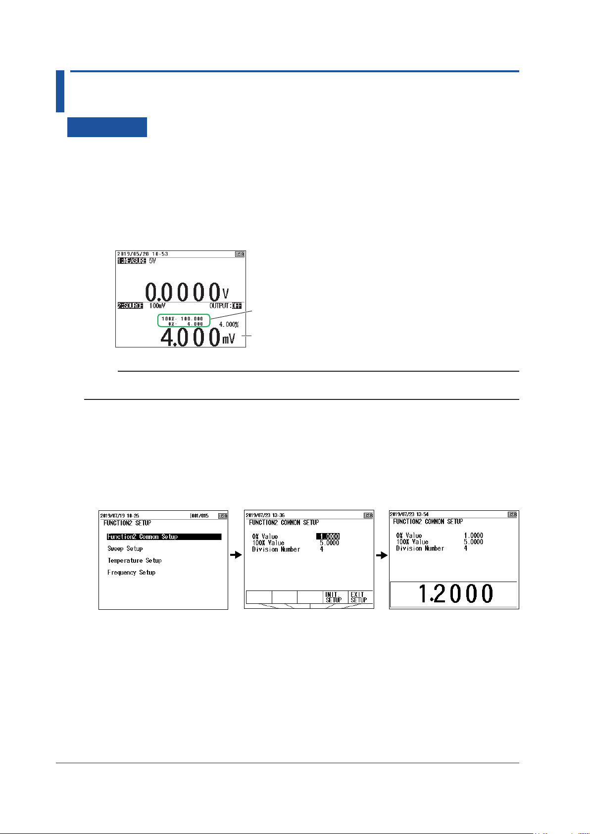
Setting Values Using the Setup Menu
1.
With the source value and measurement value displayed, press SETUP under Function 2.
2.
Use the arrow keys to select Function2 Common Setup, and then press ENTER.
3.
Use the arrow keys to select the 0% Value value, and then press ENTER. The settings are
displayed at the bottom of the screen.
4.
Use the arrow keys to set the 0% value, and then press ENTER.
5.
Likewise, set the 100% value.
6.
Press the arrow key corresponding to EXIT SETUP. The settings are confirmed, and a screen
appears showing the source value and measurement value.
The cancel the settings, press ESC to return to the screen in step 2.
To initialize the settings, press the arrow key corresponding to INIT SETUP.
2-16
IM CA500-01EN
Page 49

2.7 Setting the 0% and 100% Values
1
Generating the 0% and 100% Values
1.
With the source value and measurement value displayed, press 0% or 100%.
The source value is set to the 0% or 100% value.
2.
Press OUTPUT ON/OFF. OUTPUT:OFF on the screen changes to OUTPUT:ON, and are
displayed 0% or 100% value is generated.
To turn off the source, press OUTPUT ON/OFF again.
Description
0% and 100% Values
Set the values within each source range.
These values become the divided source range or sweep source range.
2
Source
IM CA500-01EN
2-17
Page 50
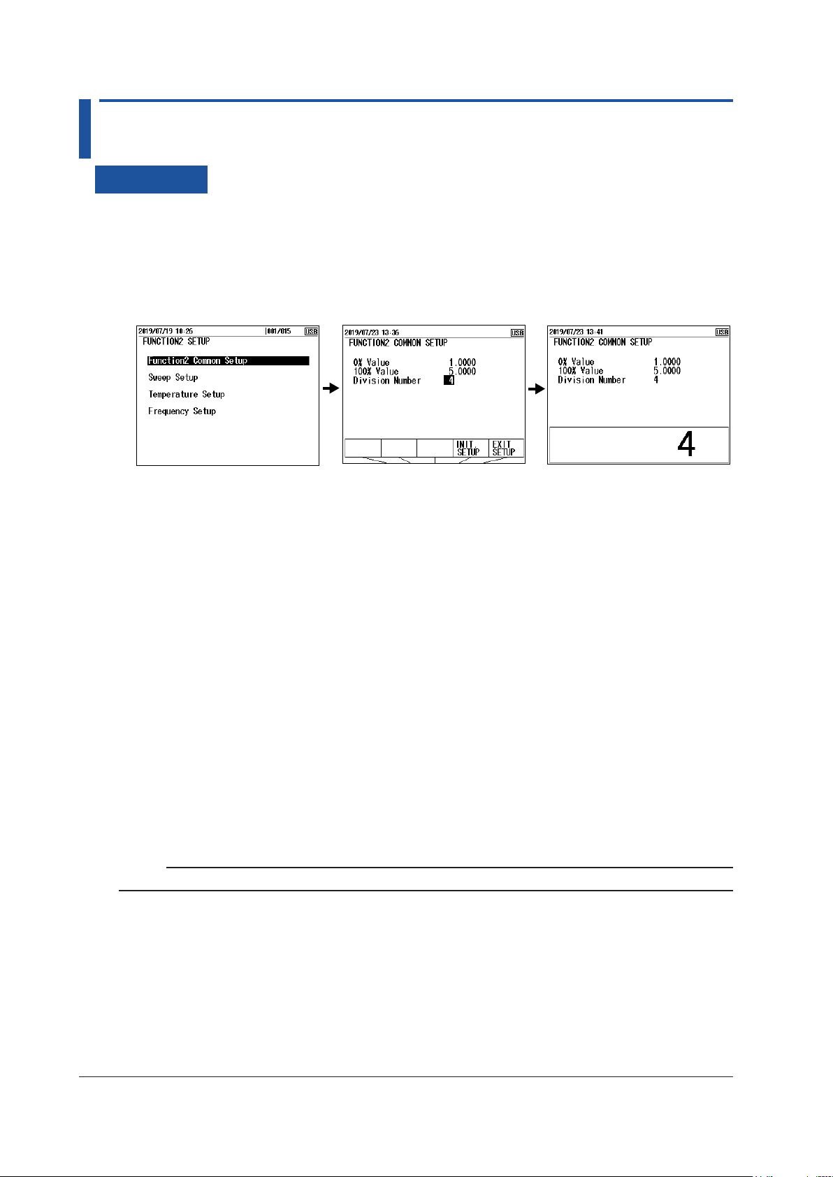
2.8 Dividing and Generating the Source Values
Procedure
Setting the Number of Divisions
1.
With the source value and measurement value displayed, press SETUP under Function 2.
2.
Use the cursor keys to select Function2 Common Setup, and then press ENTER.
3.
Use the cursor keys to select the Division Number value, and then press ENTER. The settings
are displayed at the bottom of the screen.
4.
Use the arrow keys to set the number divisions from the 0% value to the 100% value, and press
ENTER.
When the source range is 1-5V, 1-5V√, 4-20mA, 4-20mA√, or 4-20mA Simulate, the number
divisions is fixed to 4.
5.
Press the arrow key corresponding to EXIT SETUP. The settings are confirmed, and a screen
appears showing the source value and measurement value.
The cancel the settings, press ESC to return to the screen and step 2.
To initialize the settings, pressing the arrow key corresponding to INIT SETUP.
Turning the Source On and Off
6.
With the source value and measurement value displayed, press OUTPUT ON/OFF.
The displayed source value is output, and OUTPUT:OFF on the screen changes to
OUTPUT:ON.
To turn off the source, press OUTPUT ON/OFF again.
Increasing or Decreasing the Source Value
7.
Press UP or DOWN. The source value increases or decreases by the specified division width.
Note
You can change the source value to the 0% or 100% value by pressing the 0% or 100% key.
2-18
IM CA500-01EN
Page 51

2.8 Dividing and Generating the Source Values
1
Description
Number of Divisions
The range from the 0% value to the 100% value is divided and output.
For example, if the number of divisions is set to 5, the 0%, 20%, 40%, 60%, 80%, and 100% values
are generated.
You can change the source value using the UP and DOWN keys.
100%
80%
2
Source
60%
UP key
UP key
40%
UP key
20%
UP key
0%
UP key
DOWN key
DOWN key
DOWN key
DOWN key
DOWN key
The number divisions can be set in the range of 1 to 20.
When the source range is 1-5V, 1-5V√, 4-20mA, 4-20mA√, or 4-20mA Simulate, the number divisions
is fixed to 4.
Note
When you use the step sweep function, the source value of each step can be held for the same time period,
and the source value can be stepped up or down automatically (see “Step Sweep” in section 2.9, “Sweep
Source”).
IM CA500-01EN
2-19
Page 52
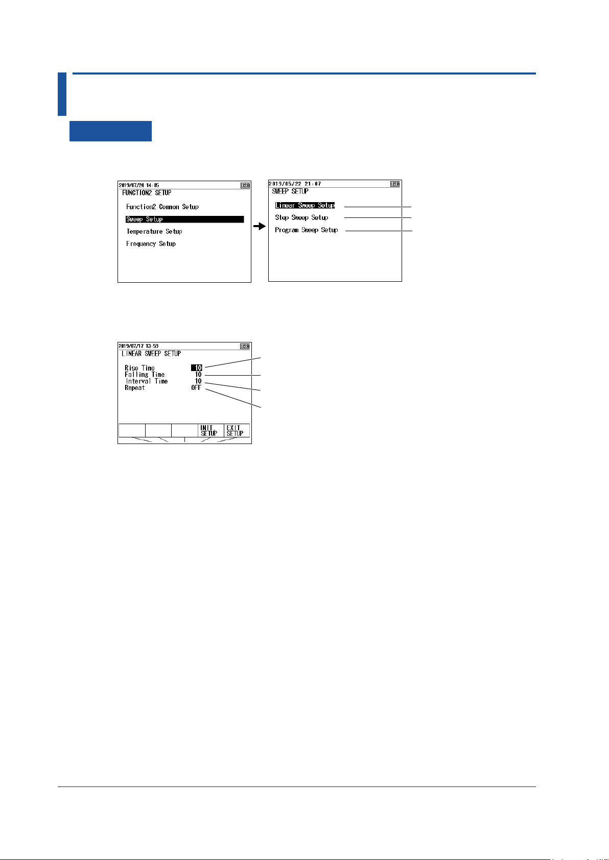
2.9 Sweep Source
Procedure
1.
With the source value and measurement value displayed, press SETUP under Function 2.
2.
Select Sweep Setup, and press ENTER.
Set the linear sweep.
Set the step sweep.
Setting and Executing Linear Sweeps
3.
Select Linear Sweep Setup, and press ENTER.
Set the rise time.
Set the fall time.
Set the interval time.
Turn repeat on or off.
Set the program sweep.
Setting the Rise and Fall Times
4.
Select Rise Time or Falling Time, press ENTER. The settings are displayed at the bottom of
the screen.
5.
Use the arrow keys to set the rise time or fall time, and press ENTER.
Setting the Interval Time
6.
Select Interval Time, and press ENTER. The settings are displayed at the bottom of the
screen.
7.
Use the arrow keys to set the interval time, and then press ENTER.
Turning Repeat On and Off
8.
Select Repeat. ON and OFF appear in the selection menu.
9.
Use the arrow keys to set the sweep repeat to ON or OFF.
Confirming the Settings
10.
Press the arrow key corresponding to EXIT SETUP. The settings are confirmed, and a screen
appears showing the source value and measurement value.
The cancel the settings, press ESC to return to the screen and step 2.
To initialize the settings, pressing the arrow key corresponding to INIT SETUP.
2-20
IM CA500-01EN
Page 53

2.9 Sweep Source
1
Executing a Linear Sweep
11.
With the source value and measurement value displayed, press SWEEP under Function 2
several times to display LINEAR SWEEP on the screen.
Press SWEEP to display
LINEAR SWEEP.
12.
Press OUTPUT ON/OFF to turn on the source.
13.
Press UP or DOWN. Sweeping starts..
When you press UP, the 0% source values displayed, and sweeping starts from 0% to 100%.
When you press DOWN, the 100% source values displayed, and sweeping starts from 100% to
0%.
If repeat is set to OFF, sweeping stops automatically after one cycle is executed. Press
OUTPUT ON/OFF to turn off the source.
2
Source
If repeat is set to ON, sweeping continues until you turn off the source.
Setting and Executing Step Sweeps
3.
Select Step Sweep Setup, and press ENTER.
Set the interval time.
Turn repetition on or off.
Setting the Interval Time
4.
Select Interval Time, and press ENTER. A list of options appears.
5.
Use the arrow keys to set the interval time, and then press ENTER.
The number of steps is determined by the number of divisions of the divided source (see
section 2.8, “Dividing and Generating the Source Values”).
Turning Repeat On and Off
Turn data save on or off.
6.
Select Repeat. ON and OFF appear in the selection menu.
7.
Use the arrow keys to set the sweep repetition to ON or OFF.
IM CA500-01EN
2-21
Page 54

2.9 Sweep Source
Turning Data Save On and Off
8.
Select Data Save. ON and OFF appear in the selection menu.
9.
Use the arrow keys to set data save to ON or OFF.
When you set this to on, the measurement values and source values are saved automatically
when the sweep is completed.
Confirming the Settings
10.
Press the arrow key corresponding to EXIT SETUP. The settings are confirmed, and a screen
appears showing the source value and measurement value.
The cancel the settings, press ESC to return to the screen and step 2.
To initialize the settings, pressing the arrow key corresponding to INIT SETUP.
Executing a Step Sweep
11.
With the source value and measurement value displayed, press SWEEP under Function 2
several times to display STEP SWEEP on the screen.
The source value display is set to the value assigned to 0%.
Press SWEEP to
display STEP SWEEP.
12.
Press OUTPUT ON/OFF to turn on the source.
13.
Press UP or DOWN. Sweeping starts.
When you press UP, the 0% source values displayed, and sweeping starts from 0% to 100%.
When you press DOWN, the 100% source values displayed, and sweeping starts from 100% to
0%.
If repeat is set to OFF, sweeping stops automatically after one cycle is executed. Press
OUTPUT ON/OFF to turn off the source.
If repeat is set to ON, sweeping continues until you turn off the source.
2-22
IM CA500-01EN
Page 55
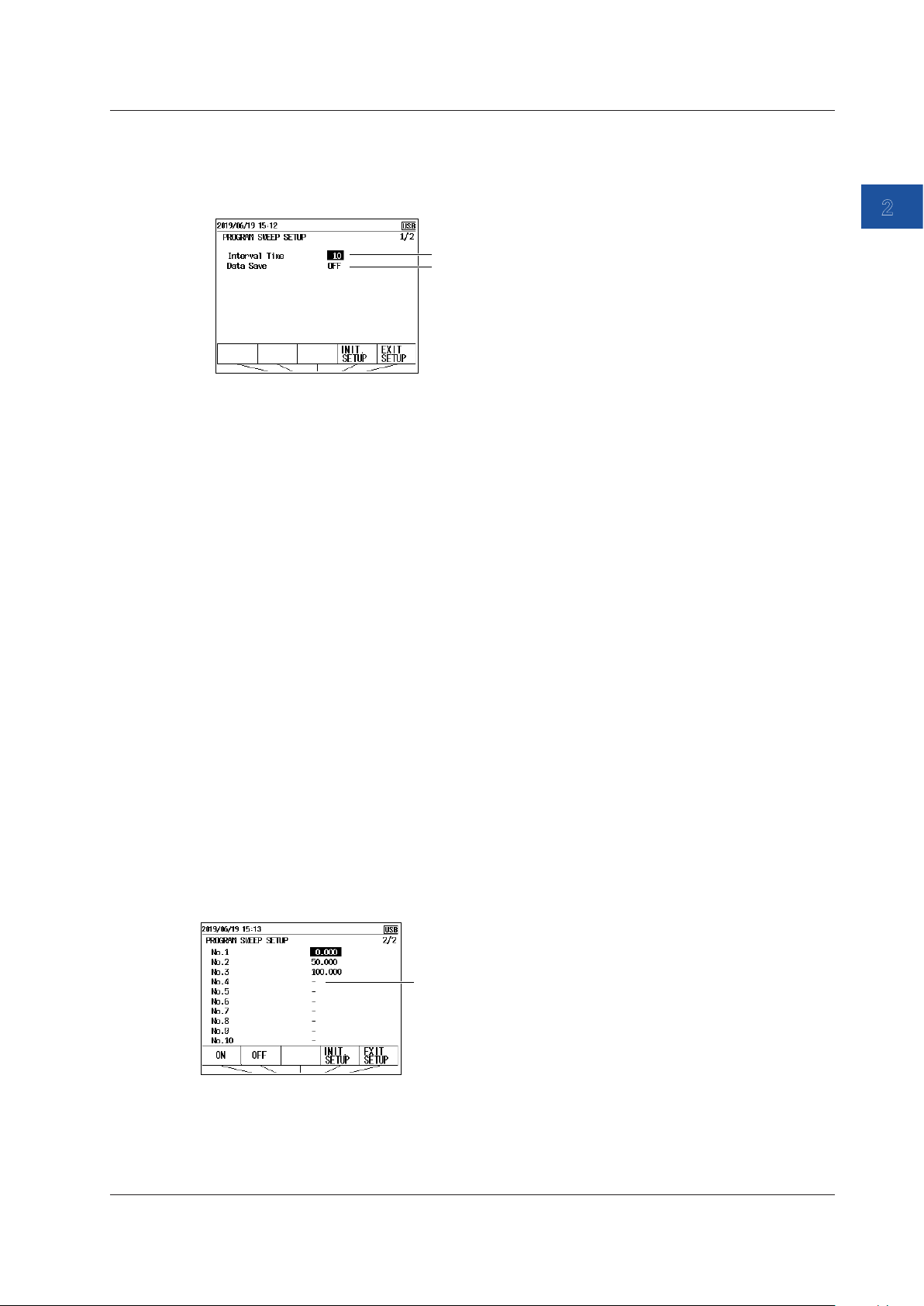
Setting and Executing Program Sweeps (CA500)
1
3.
Select Program Sweep Setup, and press ENTER.
2.9 Sweep Source
CA500
Set the interval time.
Turn data save on or off.
Setting the Interval Time
4.
Select Interval Time, and press ENTER. A list of options appears.
5.
Use the arrow keys to set the interval time, and then press ENTER.
Turning Data Save On and Off
6.
Select Data Save. ON and OFF appear in the selection menu.
7.
Use the arrow keys to set data save to ON or OFF.
When you set this to on, the measurement values and source values are saved automatically
when the sweep is completed.
Setting the Source Value
2
Source
8.
Use the cursor keys to display page 2/2 of Program Sweep Setup.
9.
Select No.1 under Output Data. ON and OFF appear.
10.
Use the arrow keys to select ON, and then press ENTER. The settings are displayed at the
bottom of the screen.
11.
Use the arrow keys to select the source value (%), and then press ENTER.
12.
Likewise, set the source values of Output Data No.2 to No.10.
For the numbers you will not use, use the arrow keys to select OFF. “-” is displayed for the
source value.
If you set a number to off, the instrument sweeps up to the last number that has a source value
assigned. Then, it returns to No.1, and continues the signal generation.
OFF
IM CA500-01EN
2-23
Page 56
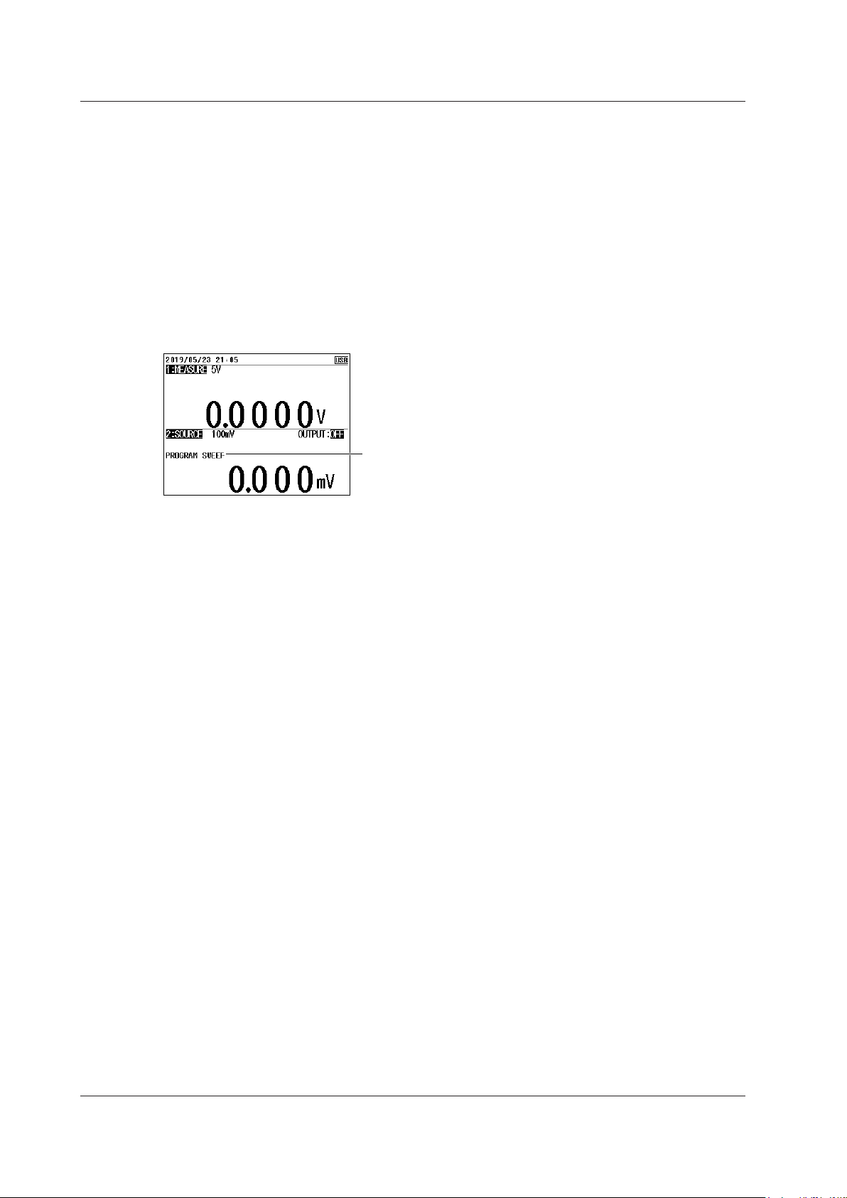
2.9 Sweep Source
Confirming the Settings
13.
Press the arrow key corresponding to EXIT SETUP. The settings are confirmed, and a screen
appears showing the source value and measurement value.
The cancel the settings, press ESC to return to the screen and step 2.
To initialize the settings, pressing the arrow key corresponding to INIT SETUP.
Executing a Program Sweep
14.
With the source value and measurement value displayed, press SWEEP under Function 2
several times to display PROGRAM SWEEP on the screen.
The source value display is set to the value assigned to source value No. 1.
Press SWEEP to display
PROGRAM SWEEP.
15.
Press OUTPUT ON/OFF to turn on the source.
16.
Press UP or DOWN.
The source values are generated in order from No. 1 according to the settings.
When the last specified number is reached, the instrument returns to No. 1 and continues the
signal generation.
To stop a sweep, press OUTPUT ON/OFF.
2-24
IM CA500-01EN
Page 57

Setting and Executing Program Sweeps (CA550)
1
3.
Select Program Sweep Setup, and press ENTER.
2.9 Sweep Source
CA550
Set the interval time.
Turn data save on or off.
Set the model of the calibration target.
Set the serial number of the calibration target.
Set the tag number of the calibration target.
Set the loop number of the calibration target.
* Output settings are on pages 2/3 and 3/3.
Setting the Interval Time
4.
Select Interval Time, and press ENTER. A list of options appears.
5.
Use the arrow keys to set the interval time, and then press ENTER.
Turning Data Save On and Off
6.
Select Data Save. ON and OFF appear in the selection menu.
7.
Use the arrow keys to set data save to ON or OFF.
When you set this to on, the measurement values and source values are saved automatically
when the sweep is completed.
Setting the Calibration Target Information (when necessary)
2
Source
8.
Select Model Number, and press ENTER. An alphanumeric character input window appears.
9.
Enter the model number of the instrument to be calibrated.
Use the cursor keys to select characters, and then press ENTER. Press the arrow key
corresponding to DONE to confirm the entered character string.
For details on the alphanumeric input window, see chapter 3, “Common Operations,” Getting
Started Guide (IM CA500-02EN).
10.
Likewise, set information for Serial Number, Tag Number, and Loop Number.
IM CA500-01EN
2-25
Page 58

2.9 Sweep Source
Setting the Source Value
11.
Use the cursor keys to display page 2/3 of Program Sweep Setup.
12.
Select No.1 under Output Data. ON and OFF appear.
13.
Use the arrow keys to select ON, and then press ENTER. The settings are displayed at the
bottom of the screen.
14.
Use the arrow keys to select the source value (%), and then press ENTER.
15.
Likewise, set the source values of Output Data No.2 to No.20.
For the numbers you will not use, use the arrow keys to select OFF. “-” is displayed for the
source value.
If you set a number to off, the instrument sweeps up to the last number that has a source value
assigned. Then, sweeping stops.
Set the source value on page 2/3 or 3/3.
OFF
Confirming the Settings
16.
Press the arrow key corresponding to EXIT SETUP. The settings are confirmed, and a screen
appears showing the source value and measurement value.
The cancel the settings, press ESC to return to the screen and step 2.
To initialize the settings, pressing the arrow key corresponding to INIT SETUP.
Executing a Program Sweep
17.
With the source value and measurement value displayed, press SWEEP under Function 2
several times to display PROGRAM SWEEP on the screen.
The source value display is set to the value assigned to source value No. 1.
Press SWEEP to display
PROGRAM SWEEP.
18.
Press OUTPUT ON/OFF to turn on the source.
19.
Press UP or DOWN.
The source values are generated in order from No. 1 according to the settings.
When the last specified number is reached, sweeping stops automatically.
To stop a sweep in progress, press OUTPUT ON/OFF.
2-26
IM CA500-01EN
Page 59

Sweep in progress
2.9 Sweep Source
1
Description
Displayed during a Sweep
While a sweep is in progress, RUNNING is displayed on the Function2 screen.
Displays RUNNING
Linear Sweep
The source value changes linearly from the 0% value to the 100% value or from the 100% value to
the 0% value.
For instructions on how to set the 0% and 100% values, see section 2.7, “Setting the 0% and 100%
Values”.
2
Source
Interval
time
Source
value
Time
100%
0%
Fall time
Sweep start (DOWN key)
Output on
Interval
time
Rise time
Interval
time
Source
value
100%
0%
Interval
time
Rise time
Sweep start (UP key)
Output on
Fall time
Note
In a linear sweep, the percent value changes linearly. In the 1-5V√ or 4-20mA√ source range, the source
voltage or current is the square root of each percentage.
Rise Time and Fall Time
These are the times during which the source value is varied from 0% to 100% or from 100% to
0%. You can specify 5 to 600 s.
Interval Time
This is the time during which the source value is held at 0% or 100% after the rise or fall time.
You can specify 5 to 600 s.
Time
IM CA500-01EN
Repeat
The interval for the signal to rise and fall or to fall and rise is considered a cycle. Set whether
to stop the sweep after one cycle (OFF) or repeat it (ON).
If you select OFF, sweeping stops after one cycle is completed. If you change the sweep
direction while sweeping is in progress, sweeping stops when the interval time elapses after
reaching the 0% or 100% value after the change.
If you select ON, sweeping continues until the source is turned off with the OUTPUT ON/OFF
key.
2-27
Page 60

Output on
t: Interval time
t: Interval time
Source
Source
2.9 Sweep Source
Operation While Sweeping Is in Progress
• If you press the UP or DOWN key while sweeping is in progress, you can change the
sweep direction.
• Pressing any of the following keys while sweeping stops the sweeping.
FUNCTION2, RANGE2, ESC, or OUTPUT
Pressing any other keys except the power key does not affect the sweeping operation. Some
keys are disabled during sweeping.
Step Sweep
The source value interval from 0% to 100% is divided equally by a specified number, and the
source value is varied stepwise.
For instructions on how to set the 0% and 100% values, see section 2.7, “Setting the 0% and 100%
Values”.
value
100%
0%
t
Sweep start (UP key)
t
t
t
t
t
t
t
t
Time
value
100%
t
t
0%
Sweep start (DOWN key)
Output on
t t
t t t
t
t
Time
Note
In a step sweep, percentages are equally divided. In the 1-5V√ or 4-20mA√ source range, the source
voltage or current is the value for square root operation.
Interval Time
The time period during which the source value of each step is held. You can specify 5 to 600 s.
Repeat
The interval for the signal to rise and fall or to fall and rise is considered a cycle. Set whether
to stop the sweep after one cycle (OFF) or repeat it (ON).
If set to OFF, sweeping stops after one cycle is executed, and sweeping stops, and the source
value is held.
If you change the sweep direction while sweeping is in progress, the source turns off when the
interval time elapses after reaching the 0% or 100% value after the change.
If you select ON, sweeping continues until the source is turned off with the OUTPUT ON/OFF
key.
2-28
Saving Data
The source value and measurement value of each step are automatically saved. The
maximum number of data values that can be saved on the CA500 is 100. The maximum
number of data values that can be saved in a single file on the CA550 is 2000, the maximum
number of files that can be saved is 250. For details, see section 5.2, “Saving Sweeps”.
Number of Divisions
The number divisions is used for divided output. See section 2.8, “Dividing and Generating the
Source Values”.
IM CA500-01EN
Page 61

2.9 Sweep Source
1
Operation While Sweeping Is in Progress
• If you press the UP or DOWN key while sweeping is in progress, you can change the
sweep direction.
• Pressing any of the following keys while sweeping stops the sweeping.
FUNCTION2, RANGE2, ESC, or OUTPUT
Pressing any other keys except the power key does not affect the sweeping operation. Some
keys are disabled during sweeping.
Program Sweep
Assigned source values in the 0% to 100% range are generated in order by number for a given
time period.
You can assign up to 10 source values on the CA500 and 20 source values on the CA550.
2
Source
Source
value
100%
0%
1
t
Output on
2
t
4
3
t
5
t
t
7
6
t
t
Source number
8
t
Interval time
Time
Interval Time
The time period during which the source value of each step is held.
You can specify 5 to 600 s.
Source Values (No.1 to No.10 (CA500), No.1 to No.20 (CA550)
Set the source values in percentages.
If not all source values are assigned and there is a source number set off or a unused source
number, the instrument sweeps up to the number that a source value is assigned to. Then,
on the CA500, the source value returns to No.1 and sweeping continues. On the CA550,
sweeping stops.
The source time of each number is the time set with the interval time.
Saving Data (Data Save)
The source value and measurement value of each step are automatically saved. The
maximum number of data values that can be saved on the CA500 is 100. The maximum
number of data values that can be saved in a single file on the CA550 is 2000, the maximum
number of files that can be saved is 250.
Calibration Target Information (Model Number, Serial Number, Tag
Number, Loop Number, CA550 only)
Set the calibration target model name, serial number, tag number, and loop number using up
to 33 characters.
The set information is included in the data that is automatically saved during sweeping.
IM CA500-01EN
2-29
Page 62

2.9 Sweep Source
Operation While Sweeping Is in Progress
Pressing any of the following keys while sweeping stops the sweeping.
FUNCTION2, RANGE2, ESC, or OUTPUT
Pressing any other keys except the power key does not affect the sweeping operation. Some
keys are disabled during sweeping.
2-30
IM CA500-01EN
Page 63

1
2
Chapter 3 Measurement
3.1 DC Voltage Measurement
Procedure
Setting the Function
1.
With the source value and measurement value displayed, press FUNCTION 1. The function
options are displayed.
2.
Use the arrow keys to select V. The display returns to the source and measurement value
display.
Set the measuring range.
3.
Under Function 1, press RANGE.
4.
Use the arrow keys to set the measurement range. The display returns to the source and
measurement value display.
3
Measurement
Setting the 0% and 100% Values (when necessary)
5.
Set the 0% and 100% values according to section 3.7, “Setting the 0% and 100% Values”.
IM CA500-01EN
3-1
Page 64
3.1 DC Voltage Measurement
Description
Measurement Range
You can select from the following three measurement ranges.
Range Measurement Range
100 mV ±110.000 mV
5 V ±6.0000 V
50 V ±55.000 V
0% Value and 100% Value
Assign an output value (specified according to the specifications of the device to be calibrated) to
the 0% or 100% measurement value of this instrument, which is mapped to the 0% or 100% source
value of this instrument.
The instrument displays errors, pass/fail judgment results (CA550), measurement percentages
relative to the assigned value.
3-2
IM CA500-01EN
Page 65

1
2
3.2 DC Current Measurement
Procedure
Setting the Function
1.
With the source value and measurement value displayed, press FUNCTION 1. The function
options are displayed.
2.
Use the arrow keys to select mA. The display returns to the source and measurement value
display.
Set the measuring range.
3.
Under Function 1, press RANGE.
4.
Use the arrow keys to set the measurement range. The display returns to the source and
measurement value display.
3
Measurement
Setting the 0% and 100% Values (when necessary)
5.
Set the 0% and 100% values according to section 3.7, “Setting the 0% and 100% Values”.
Loop Power Source (when performing loop tests)
6.
Press LOOP POWER. LOOP on the screen is turned on, and the instrument generates a 24
VDC loop power.
To stop the source, press LOOP POWER again.
IM CA500-01EN
3-3
Page 66
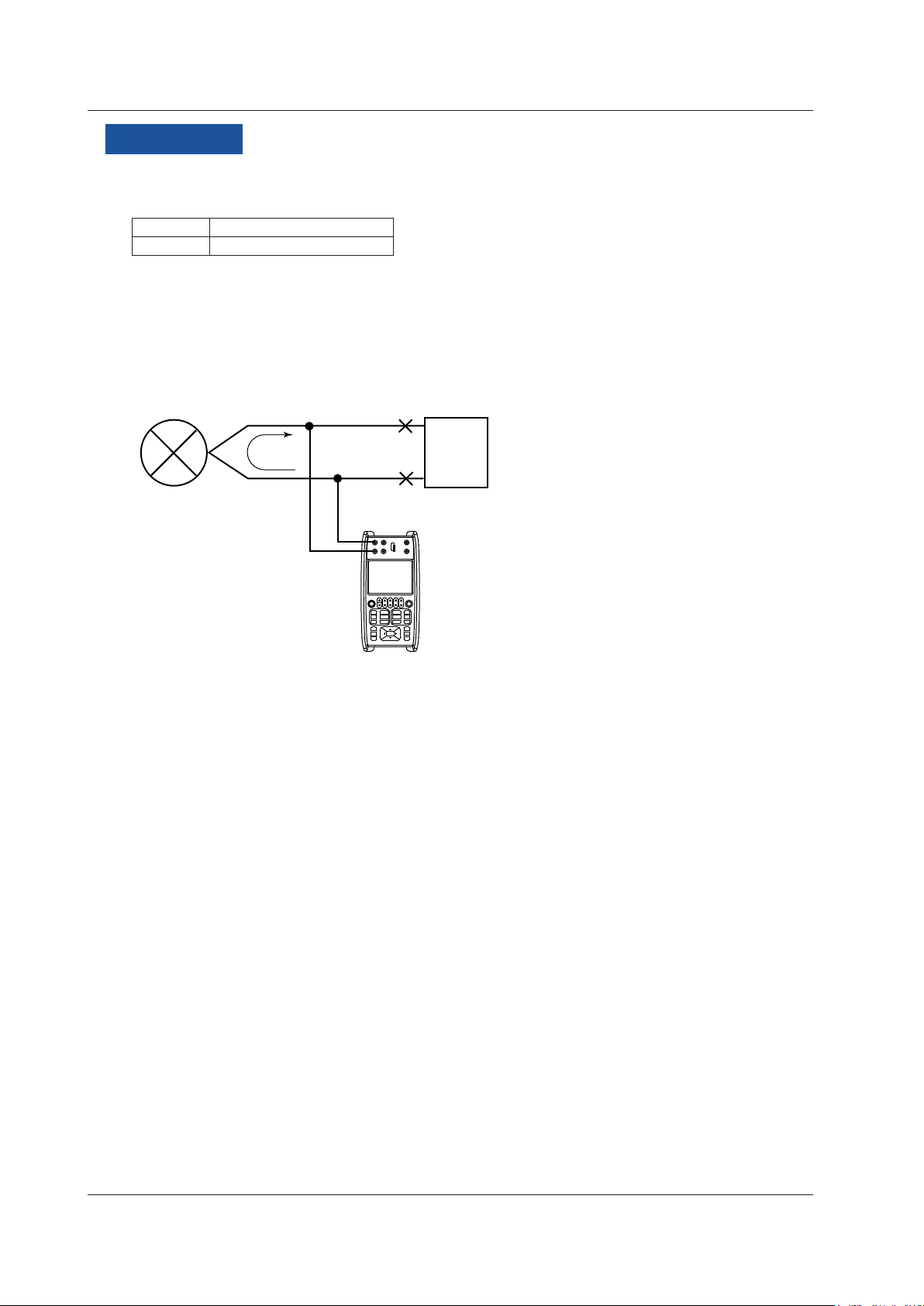
3.2 DC Current Measurement
Description
Measurement Range
The only available measurement range is 50 mA.
Range Measurement Range
50 mA ±60.000 mA
Loop Power
Loop power can be generated during DC current measurement.
Transfer signals can be measured while supplying a constant voltage of 24 VDC to the two-wire
transmitter.
The two-wire transmitter and distributor are not connected.
—
H
L
Distributor
+
Two-wire transmitter
4-20mA
24 VDC
CA500/CA550
3-4
IM CA500-01EN
Page 67
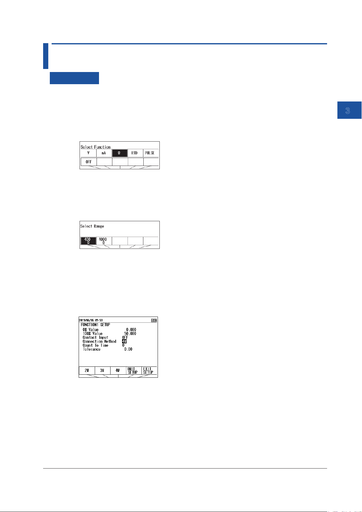
1
2
3.3 Resistance Measurement
Procedure
Setting the Function
1.
With the source value and measurement value displayed, press FUNCTION 1. The function
options are displayed.
2.
Use the arrow keys to select Ω. The display returns to the source and measurement value
display.
Set the measuring range.
3.
Under Function 1, press RANGE.
4.
Use the arrow keys to set the measurement range. The display returns to the source and
measurement value display.
3
Measurement
Setting the 0% and 100% Values (when necessary)
5.
Set the 0% and 100% values according to section 3.7, “Setting the 0% and 100% Values”.
Setting the Wiring System
6.
With the source value and measurement value displayed, press SETUP under Function 1.
7.
User cursor keys to select Connection Method. Wiring systems appear in the selection menu.
8.
Use the arrow keys to set the wiring system.
9.
Press the arrow key corresponding to EXIT SETUP. The settings are confirmed, and the screen
reverts to show the source value and measurement value.
The cancel the settings, press ESC to return to the screen and step 6.
To initialize the settings, pressing the arrow key corresponding to INIT SETUP.
IM CA500-01EN
3-5
Page 68

3.3 Resistance Measurement
Description
Measurement Range
You can select from the following two measurement ranges.
Range Measurement Range
400Ω 0.00 Ω ~ 440.00 Ω
4000Ω 0.0 Ω ~ 4400.0 Ω
Wiring Systems
You can select from 2W (two-wire), 3W (three-wire), and 4W (four-wire).
This setting is shared with the RTD.
3-6
IM CA500-01EN
Page 69
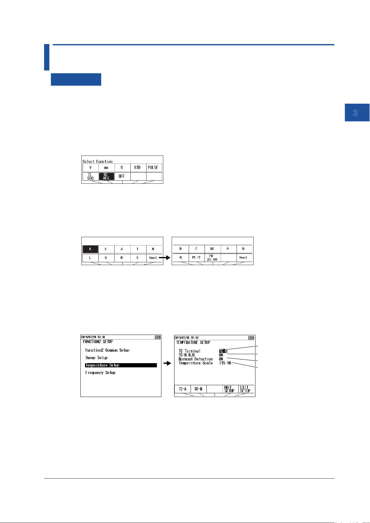
1
2
3.4 Temperature Measurement Using Thermocouples
Procedure
Setting the Function
1.
With the source value and measurement value displayed, press FUNCTION 2. The function
options are displayed.
Temperature measurement using a thermocouple is configured using Function 2.
2.
Use the arrow keys to select TC MES (Measure). The display returns to the source and
measurement value display.
Setting the Measurement Range (TC Type)
3.
Under Function 2, press RANGE.
4.
Use the arrow keys to set the TC type. The display returns to the source and measurement
value display.
3
Measurement
Setting the 0% and 100% Values (when necessary)
5.
Set the 0% and 100% values according to section 3.7, “Setting the 0% and 100% Values”.
Selecting the Terminal
6.
With the source value and measurement value displayed, press SETUP under Function 2.
7.
Select Temperature Setup, and press ENTER. A Temperature Setup setup screen appears.
Set the terminal.
Set the RJC sensor.
8.
Select TC Terminal. TC-A and TC-B appear in the selection menu.
9.
Using the arrow keys, select TC-A to use the TC-A terminal (thermocouple mini plug) or TC-B
to use TC-B.
Turn burnout on or off.
Set the temperature
scale.
To finish entering the settings here, proceed to step 16.
IM CA500-01EN
3-7
Page 70

3.4 Temperature Measurement Using Thermocouples
Setting the Reference Junction Compensation (RJC) (when using the TC-B
terminal)
10.
Select TC-B RJC. ON and OFF appear in the selection menu.
11.
Use the arrow keys to set RJC to ON or OFF.
To finish entering the settings here, proceed to step 16.
Turning Burnout On and Off
12.
Select Burnout Detection. ON and OFF appear in the selection menu.
13.
Using the arrow keys, select ON to use burnout detection or OFF otherwise.
To finish entering the settings here, proceed to step 16.
Setting the Temperature Scale
14.
Select Temperature Scale. Options appear in the selection menu.
15.
Use the arrow keys to set the temperature scale.
Confirming the Settings
16.
Press the arrow key corresponding to EXIT SETUP. The settings are confirmed, and the screen
reverts to show the source value and measurement value.
The cancel the settings, press ESC to return to the screen and step 6.
To initialize the settings, pressing the arrow key corresponding to INIT SETUP.
Description
Measurement Range (TC Type)
Set the TC type to use.
TC type (thermocouple) Measurement range
K -200.0°C to +1372.0°C
E -250.0°C to +1000.0°C
J -210.0°C to +1200.0°C
T -250.0°C to +400.0°C
N -200.0°C to +1300.0°C
L -200.0°C to +900.0°C
U -200.0°C to +600.0°C
R -20.0°C to +1767.0°C
S -20.0°C to +1768.0°C
B +600.0°C to +1820.0°C
C 0.0°C to +2315.0°C
XK -200.0°C to +800.0°C
A 0.0°C to +2500.0°C
D (W3Re/W25Re) 0.0°C to +2315.0°C
G (W/W26Re) +100.0°C to +2315.0°C
PLATINEL II 00.0°C to +1395.0°C
PR20-40 0.0°C to +1888.0°C
3-8
IM CA500-01EN
Page 71

1
2
3.4 Temperature Measurement Using Thermocouples
Input Terminal
Set whether to use the TC-A terminal (dedicated thermocouple mini plug) or TC-B terminal.
If you select TC-A, you cannot use an external RJ sensor (sold separately).
When using the TC-B, we recommend that you use the included binding post (99045).
Turning Reference Junction Compensation (RJC) On and Off
When using the TC-B terminal (banana terminal), set whether to perform RJC (ON/OFF).
ON: If an external RJ sensor is connected, the external RJ sensor is used to perform
reference junction compensation.
If an external RJ sensor is not connected, the internal RJ sensor is used to perform
reference junction compensation.
OFF: Reference junction compensation is not performed.
When the TC-A terminal is used, the internal temperature sensor is always used to perform
reference junction compensation.
Note
• The internal RJ sensor measures the temperature of the instrument’s terminal.
• When the temperature inside the instrument is high, wait for the temperature to decrease before use.
• For the external RJ sensor, use the 90080 RJ sensor, sold separately.
3
Measurement
Burnout
When burnout detection is turned on, the instrument detects burnouts in the thermocouple circuit
and displays “B.OUT (Burnout)” on the screen.
Temperature Scale
You can select from the following temperature scales.
IPTS-68: The international temperature scale standard of 1968
ITS-90: The international temperature scale standard of 1990
Notes about Measurement
If you perform a temperature measurement or temperature source using an RJC immediately after
using loop power or simulating 20 mA, the measured value or source value may be affected by the
temperature rise inside the instrument. Wait for the temperature inside instrument to stabilize before
using it.
IM CA500-01EN
3-9
Page 72
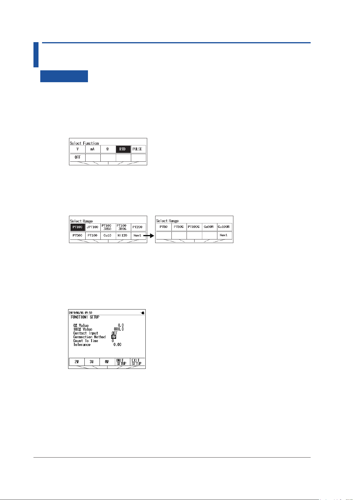
3.5 Temperature Measurement Using RTDs
Procedure
Setting the Function
1.
With the source value and measurement value displayed, press FUNCTION 1. The function
options are displayed.
2.
Use the arrow keys to select RTD. The display returns to the source and measurement value
display.
Setting the Measurement Range (RTD Type)
3.
Under Function 1, press RANGE.
4.
Use the arrow keys to set the RTD type. The display returns to the source and measurement
value display.
Setting the 0% and 100% Values (when necessary)
5.
Set the 0% and 100% values according to section 3.7, “Setting the 0% and 100% Values”.
Setting the Wiring System
6.
With the source value and measurement value displayed, press SETUP under Function 1.
7.
User cursor keys to select Connection Method. Wiring systems appear in the selection menu.
8.
Use the arrow keys to set the wiring system.
9.
Press the arrow key corresponding to EXIT SETUP. The settings are confirmed, and the screen
reverts to show the source value and measurement value.
The cancel the settings, press ESC to return to the screen and step 6.
To initialize the settings, pressing the arrow key corresponding to INIT SETUP.
3-10
IM CA500-01EN
Page 73

1
2
3.5 Temperature Measurement Using RTDs
Description
Measurement Range (RTD Type)
Set the RTD type to use.
RTD Measurement Range
PT100 (PT100 JIS (3851)) -200.0°C to 800.0°C
JPT100 (PT100 former JIS (3916)) -200.0°C to 510.0°C
PT100 (3850) -200.0°C to 630.0°C
PT100 (3926) -200.0°C to 630.0°C
PT200 -200.0°C to 630.0°C
PT500 -200.0°C to 630.0°C
PT1000 -200.0°C to 630.0°C
Cu10 -100.0°C to 260.0°C
Ni120 -80.0°C to 260.0°C
PT50 -200.0°C to 630.0°C
PT50G -200.0°C to 800.0°C
PT100G -200.0°C to 630.0°C
Cu50M -180.0°C to 200.0°C
Cu100M -180.0°C to 200.0°C
Wiring Systems
You can select from 2W (two-wire), 3W (three-wire), and 4W (four-wire).
This setting is shared with resistance measurement.
3
Measurement
IM CA500-01EN
3-11
Page 74

3.6 Frequency and Pulse Measurement
Procedure
Setting the Function
1.
With the source value and measurement value displayed, press FUNCTION 1. The function
options are displayed.
2.
Use the arrow keys to select PULSE. The display returns to the source and measurement value
display.
Setting the Measurement Range
3.
Under Function 1, press RANGE.
4.
Use the arrow keys to set the measurement range. The display returns to the source and
measurement value display.
Setting the 0% and 100% Values (when necessary)
5.
Set the 0% and 100% values according to section 3.7, “Setting the 0% and 100% Values”.
Setting the Contact Input and Setting the Count Time of the Pulse Count (when
the measurement range is set to PULSE COUNT)
6.
With the source value and measurement value displayed, press SETUP under Function 1.
7.
User cursor keys to select Contact Input. Options appear in the selection menu.
Set the contact input.
8.
Use the arrow keys to set the contact input.
9.
Use the cursor keys to select Count To Time, and then press ENTER. The settings are
displayed at the bottom of the screen.
Set the count time.
10.
Use the arrow keys to select the measurement time, and then press ENTER.
You can set the measurement range to 1 minute to 60 minutes in steps of number 1 minute.
3-12
IM CA500-01EN
Page 75
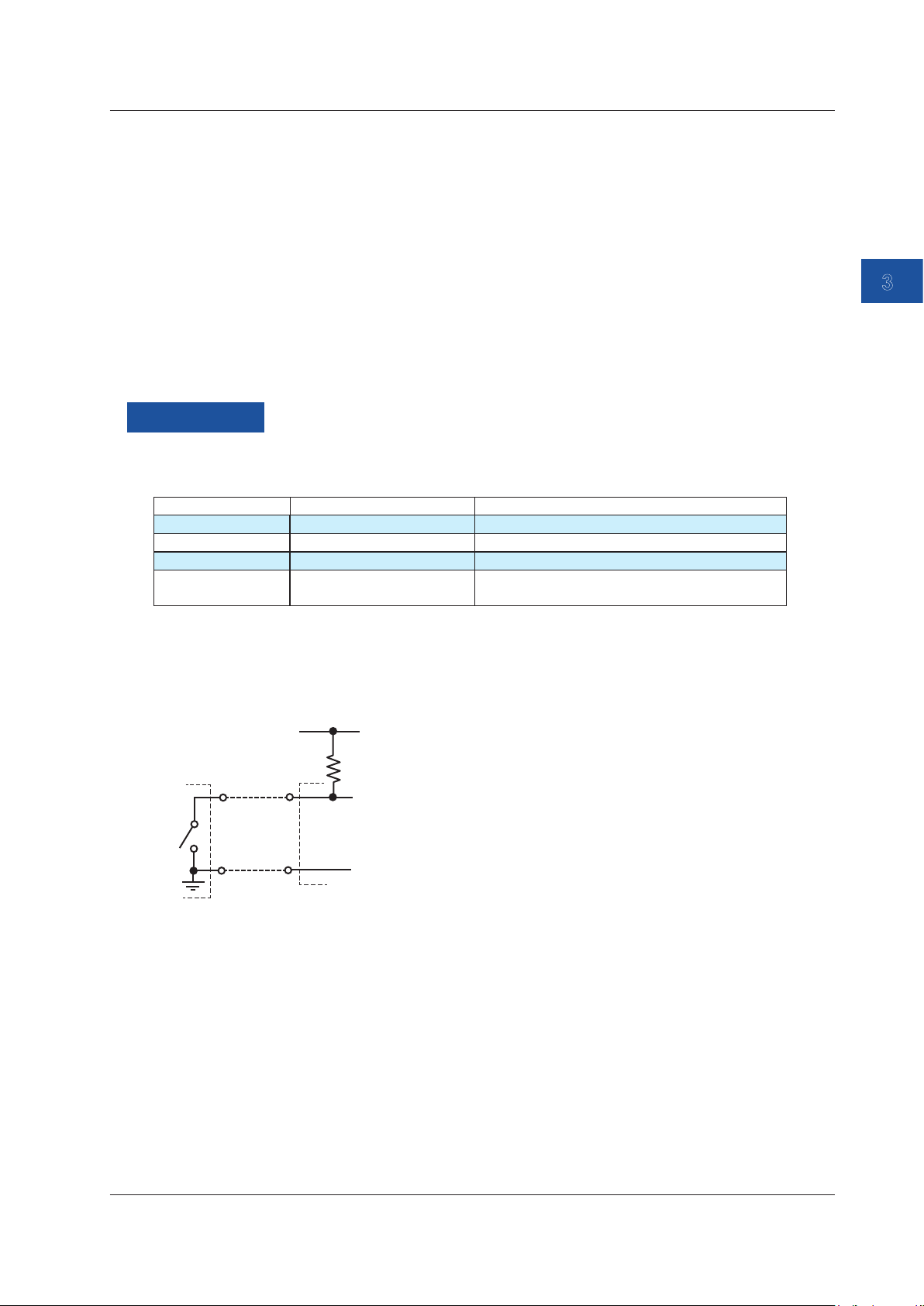
1
2
Measurement
signal
Approx. 100 kΩ
Vcc (approx. 5 V)
3.6 Frequency and Pulse Measurement
11.
Press the arrow key corresponding to EXIT SETUP. The settings are confirmed, and the screen
reverts to show the source value and measurement value.
The cancel the settings, press ESC to return to the screen and step 6.
To initialize the settings, pressing the arrow key corresponding to INIT SETUP.
Starting a Pulse Count (When the Measurement Range Is COUNT)
12.
With the source value and measurement value displayed, press ENTER.
RUNNING and the count time are displayed on the Function1 screen.
When the measurement time elapses, pulse count stops automatically.
To cancel counting while pulse count is in progress, press ENTER again.
Description
Measurement Range
You can select from the following four measurement ranges.
Range Measurement Range Notes
500 Hz 1.00 Hz to 550.00 Hz frequency, measuring
5000 Hz 1.0 Hz to 5500.0 Hz frequency, measuring
50 kHz 0.001 kHz to 50.000 kHz frequency, measuring
PULSE COUNT 0 to 99999 The number of pulses is counted within a unit
time period.
3
Measurement
Contact Input
The frequency (when the range is set to 500 Hz, 5000 Hz, or 50 kHz) at which the contact turns on
or off is measured. Or, the on/off count (when the range is set to PULSE COUNT) is taken.
H
L
H
L
The instrument’s
input terminal
Count Time of the Pulse Count
Set the time for counting pulses in units of minutes.
When the contact input is on, this is the time over which the number of on/off iterations of the
contact is counted.
Displaying the Measured Values
When the measurement signal frequency is low, it may take some time before the measurement
result is displayed. During this time, the screen displays “- - - - -.”
If the frequency is outside the measurement range, “OL” is displayed.
IM CA500-01EN
3-13
Page 76

3.7 Setting the 0% and 100% Values
Procedure
Measurements Other Than Temperature Measurements Using a
Thermocouple
1.
With the source value and measurement value displayed, press SETUP under Function 1.
2.
Use the cursor keys to select the 0% Value value, and then press ENTER. The settings are
displayed at the bottom of the screen.
3.
Use the arrow keys to select the 0% value, and then press ENTER.
4.
Likewise, set the 100% value.
5.
Press the arrow key corresponding to EXIT SETUP. The settings are confirmed, and the screen
reverts to show the source value and measurement value.
The cancel the settings, press ESC to return to the screen and step 1.
To initialize the settings, pressing the arrow key corresponding to INIT SETUP.
Temperature Measurements Using a Thermocouple
1.
With the source value and measurement value displayed, press SETUP under Function 2.
2.
Use the cursor keys to select Function2 Common Setup, and then press ENTER. A screen
appears for setting the 0% and 100% values.
3.
Use the cursor keys to select the 0% Value value, and then press ENTER. The settings are
displayed at the bottom of the screen.
4.
Use the arrow keys to select the 0% value, and then press ENTER.
5.
Likewise, set the 100% value.
6.
Press the arrow key corresponding to EXIT SETUP. The settings are confirmed, and the screen
reverts to show the source value and measurement value.
The cancel the settings, press ESC to return to the screen and step 1.
To initialize the settings, pressing the arrow key corresponding to INIT SETUP.
3-14
IM CA500-01EN
Page 77

1
2
3.7 Setting the 0% and 100% Values
Switching the Display
1.
When making measurements other than temperature measurements using a thermocouple,
press DISPLAY under Function1. When measuring temperature using a thermocouple, press
DISPLAY under Function2. The measurement value and percentage displays switch.
Measurements other than temperature
measurements using a thermocouple
Measured value
0% and 100% values
% display of the
measured value
% display of the
measured value
Measured
value
3
Measurement
Measured value
Temperature measurement
using a thermocouple
0% and 100% values
% display of the
measured value
% display of the
measured value
Measured
value
Description
0% and 100% Values
Assign an output value (specified according to the specifications of the device to be calibrated) to
the 0% or 100% measurement value of this instrument, which is mapped to the 0% or 100% source
value of this instrument.
The instrument displays errors, pass/fail judgment results (CA550), measurement percentages
relative to the assigned value.
IM CA500-01EN
3-15
Page 78

3.8 Setting the Tolerance (CA550)
Procedure
1.
With the source value and measurement value displayed, press SETUP under Function 1.
2.
Use the cursor keys to select the Tolerance value, and then press ENTER. The settings are
displayed at the bottom of the screen.
3.
Use the arrow keys to select the tolerance, and then press ENTER. The range is 0.00 to
10.00%.
4.
Press the arrow key corresponding to EXIT SETUP. The settings are confirmed, and the screen
reverts to show the source value and measurement value.
The cancel the settings, press ESC to return to the screen and step 1.
To initialize the settings, pressing the arrow key corresponding to INIT SETUP.
Description
Set the tolerance relative to the reference value for making pass/fail judgments on measurement
values.
The reference value is an output value (specified according to the specifications of the device to be
calibrated) mapped to this instrument’s source value (the input value to the device to be calibrated).
The pass/fail judgment result is recorded in the file saved by the CA550 program sweep.
For details on saving program sweeps, see section 5.2, “Saving Sweeps.”
3-16
IM CA500-01EN
Page 79

1
2
3.9 Average Value Display
Maximum
Average
Minimum
Procedure
1.
With the source value and measurement value displayed, press AVERAGE under Function 1.
The average, maximum, and minimum values are displayed on the FUNCTION 1 screen.
Description
Moving average values for every five measured values and the maximum value (MAX) and
minimum value (MIN) of the moving average values are displayed.
3
Measurement
IM CA500-01EN
3-17
Page 80

Chapter 4 Calibrating Field Instruments (CA550)
1
2
3
4.1 Calibration Procedure
This section explains how to calibrate field instruments using the CA550 program sweep.
Workflow
Start
Setup
Calibration before adjustment
(As Found)
Adjust the field instrument
Calibration after adjustment
(As Left)
Within the
specifications?
End
Set the source, measurement, and program
sweep according to the calibration target.
Execute a program sweep
(Save the device information, source value,
measurement value, judgment result)
Execute a program sweep
(Save the device information, source value,
measurement value, judgment result)
4
Calibrating Field Instruments (CA550)
Calibration before Adjustment
Before adjusting a field instrument, check the output value at each calibration point.
Apply a signal to the device to be calibrated using the source function of this instrument and
measure the output signal on this instrument.
Compare the value measured on this instrument to the specifications of the device to be calibrated.
The instrument’s source values, measurement values, judgment results, and calibration target
information are saved in this instrument in CSV format.
Calibration after Adjustment
After adjustment, check whether the output from the device to be calibrated is within the
specifications at the same calibration points as those of the calibration before adjustment. If further
adjustment is necessary, perform readjustment and calibration again.
By comparing the calibration data before adjustment and calibration data after adjustment, you can
maintain the continuity in the measurement values of the field instrument.
IM CA500-01EN
4-1
Page 81
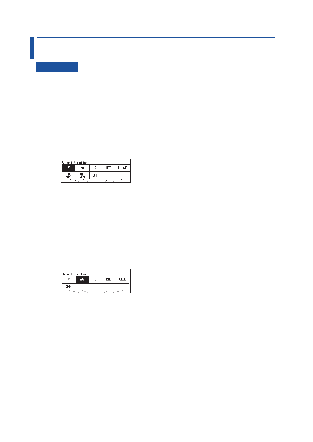
4.2 Setting Calibration Conditions
Procedure
Setting the Source and Measurement
Set the source range and measurement range of this instrument according to the input signal and
output signal of the device to be calibrated.
Setting the Source Range (Function 2)
For details on the source range, see chapter 2.
1.
With the source value and measurement value displayed, press FUNCTION 2. The function
options are displayed.
2.
Use the arrow keys to set the function of your choice. The display returns to the source and
measurement value display.
3.
Under Function 2, press RANGE.
4.
Use the arrow keys to set the source range. The display returns to the source and measurement
value display.
Setting the Measurement Range (Function 1)
For details on the measurement range, see chapter 3.
1.
With the source value and measurement value displayed, press FUNCTION 1. The function
options are displayed.
2.
Use the arrow keys to set the function of your choice. The display returns to the source and
measurement value display.
3.
Under Function 1, press RANGE.
4.
Use the arrow keys to set the measurement range. The display returns to the source and
measurement value display.
4-2
IM CA500-01EN
Page 82

4.2 Setting Calibration Conditions
1
2
3
Setting a Program Sweep
Set the program sweep to generate signals at each calibration point.
For details on program sweep, see section 2.9, “Sweep Source”.
1.
With the source value and measurement value displayed, press SETUP under Function 2.
2.
Select Sweep Setup, and press ENTER.
3.
Select Program Sweep Setup, and press ENTER.
Set the interval time.
Turn data save on or off.
Set the model of the calibration target.
4.
Set the interval time, data save, and device information.
Set data save to on.
Set the serial number of the calibration target.
Set the tag number of the calibration target.
Set the loop number of the calibration target.
* Output settings are on pages 2/3 and 3/3.
Setting the Source Value
5.
Use the cursor keys to display page 2/3 of Program Sweep Setup.
6.
Set the source value of each calibration point in order by number from No. 1.
If a number is set to OFF, the instrument sweeps up to that number and sweeping stops.
4
Calibrating Field Instruments (CA550)
Set the source value on
page 2/3 or 3/3.
OFF
Confirming the Settings
7.
Press the arrow key corresponding to EXIT SETUP. The settings are confirmed, and a screen
appears showing the source value and measurement value.
The cancel the settings, press ESC to return to the screen and step 2.
To initialize the settings, pressing the arrow key corresponding to INIT SETUP.
IM CA500-01EN
4-3
Page 83

4.2 Setting Calibration Conditions
Setting the Tolerance
1.
With the source value and measurement value displayed, press SETUP under Function 1.
2.
Use the cursor keys to select Tolerance, and then press ENTER.
3.
Use the arrow keys to select the tolerance, and then press ENTER. The range is 0.00 to
10.00%.
4.
Press the arrow key corresponding to EXIT SETUP. The settings are confirmed, and the screen
reverts to show the source value and measurement value.
The cancel the settings, press ESC to return to the screen and step 1.
To initialize the settings, pressing the arrow key corresponding to INIT SETUP.
Description
A field instrument is calibrated using the source function, measurement function, and program
sweep.
Tolerance
Set the tolerance for judging measurement values as a percentage.
Set the tolerance as a percentage of the output value specified according to the specifications of
the device to be calibrated.
Judging Measurement Values
Measurement results are judged pass or fail depending on whether the measurement values are
within the tolerance.
Judgment results are saved along with the tolerance and the differences between the measurement
values and reference values.
4-4
IM CA500-01EN
Page 84

1
2
3
4.3 Saving Calibration Results
By setting Data Save of the program sweep function to ON, you can save source values,
measurement values, judgment results, device information, and so on in CSV format.
The saved data can be displayed on this instrument or saved to a PC.
For details on the data format, see section 5.5, “Saved Data Format (CA550)”.
Note
• On this instrument, you can set the data separator of CSV files to comma, semicolon, or tab. When
opening a CSV file in Excel or the like, check the data separator setting that was used when the data
was saved.
• If the operating system of the PC connected to this instrument is Windows 8.1, you need to install a CDC
system definition file for YOKOGAWA products in the PC.
For details on how to obtain the system definition file, access the following YOKOGAWA’s webpage, and
download the file.
https://www.yokogawa.com/jp-ymi/tm/F-SOFT/
Displaying Saved Data
See section 5.3, “Loading and Deleting Saved Data”.
Saving Data to a PC
section 5.4, “Copying Saved Data to a PC (CA550)”See
4
Calibrating Field Instruments (CA550)
IM CA500-01EN
4-5
Page 85

1
2
3
4
Chapter 5 Saving Data
5.1 Saving Data Manually
Procedure
1.
While sourcing or measurement is in progress, press SAVE. The source value and
measurement value are saved to the internal memory of this instrument when SAVED is
pressed.
Description
The method to save data is different between the CA500 and CA550.
CA500
You can save the date and time, the selected function, range, measurement value, and source
value when SAVE is pressed.
Number of Data Values That Can Be Saved
A total of up to 100 data entries can be saved including the saved sweep data.
Memory numbers from 001 to 100 are automatically assigned to the data entries.
Saving is not possible beyond 100 data entries. Delete unneeded data.
List of saved data
5
Saving Data
Saves up to 100 data entries
Data Format
The format that data is saved in is exclusive to this instrument.
You can load and display the data on this instrument. For instructions on how to load data, see
section 5.3, “Loading and Deleting Saved Data”.
Data can also be loaded into a PC using communication commands.
Saved Information
The following information is saved.
Function1 Information
Saved data Notes
Measured value
Function
Range
0% value
100% value
Contact input setting
Count time
IM CA500-01EN
5-1
Page 86

5.1 Saving Data Manually
Function2 Information
Saved data Notes
Source value
Function
Range
0% value
100% value
Temperature setting Thermocouple terminal setting TC-A/TC-B
TC-B RJC setting ON/OFF
Burnout setting ON/OFF
TC scale standard setting IPTS-68/ITS-90
Temperature unit °C
Frequency setting Amplitude voltage setting
Pulse count setting
TC measurement
settings
Contact output setting ON/OFF
0% value
100% value
CA550
You can save to a CSV file the date and time, the selected range, measurement value, and source
value when SAVE is pressed.
Number of Data Values and Files That Can Be Saved
The maximum number of data entries that can be saved in a single CSV file is 2000.
Data is saved to the same file until any of the following conditions is met.
• When the FUNCTION1 SETUP or FUNCTION2 SETUP is changed
• When the function or range of Function 1 and Function 2 is changed
• When the number of save data points exceeds 2000
• When the power is turned off
Up to 250 CSV files can be saved.
Data Format
The data save format is CSV.
You can save data to a PC through USB and open it using Excel or other PC software
applications.
The data separator is the symbol specified in section 6.4, “Setting the Decimal Symbol and
CSV Separator”.
File Name
The following file name is automatically assigned.
YYYYMMDDhhmmss_xx.csv
YYYYMMDDhhmmss: year, month, day, hour, minute, and second when the first data
entry was saved
YYYY: year, MM: month, DD: day, hh: hour, mm: minute, ss: second
xx: A sequence number starting from 00 that is assigned when the save date and time
overlaps
5-2
IM CA500-01EN
Page 87

1
2
3
4
5.1 Saving Data Manually
Saved Information
The following information is saved.
Saved data Notes
MODEL CA550
FILE TYPE 0: Manually saved data using the SAVE key
1: Automatically saved data by a step sweep
2: Calibration data by a program sweep
CSV SEPARATOR 0: Comma, 1: Semicolon, 2: Tab
DECIMAL POINT 0: Period, 1: Comma
DATE FORMAT 0: YYYY/MM/DD
1: DD/MM/YYYY
2: MM/DD/YYYY
Range Measurement range, source range
0% VALUE
100% VALUE
CONTACT (contact I/O) 0: OFF, 1:ON
TC SETTING
(temperature setting)
FREQUENCY SETTING
(frequency setting)
No. Number
DATE Measurement date YYYY/MM/DD
TIME Measurement time hh:mm:ss
MEASURE Measurement value
SOURCE Source value
Thermocouple terminal setting. 0: TC-A, 1: TC-B
TC-B RJC setting. 0: OFF, 1:ON
Burnout setting. 0: OFF, 1:ON
TC scale standard setting. 0: ITS-90, 1:IPTS-68
Temperature unit. 0: °C
Amplitude voltage setting
Pulse count setting
5
Saving Data
IM CA500-01EN
5-3
Page 88

5.2 Saving Sweeps
Procedure
1.
Set DATA SAVE to ON in the step sweep or program sweep settings according to section 2.9,
“Sweep Source”.
2.
Execute a sweep. After the sweep is completed, the source values and measurement values of
each step are saved.
Description
When a step sweep or program sweep is completed, the source values and measurement values
of each step are saved automatically.
CA500
The saved information is the same as that explained in “Saving Data Manually” and Section 5.1.
A total of up to 100 data entries can be saved including manually save data.
Depending on the number-of-steps setting, 100 data entries may be exceeded when a sweep is
saved. In this situation, an error message is displayed when a sweep is started.
Data is saved in a dedicated format of this instrument.
If you abort a sweep, the data up to that point is saved.
5-4
IM CA500-01EN
Page 89
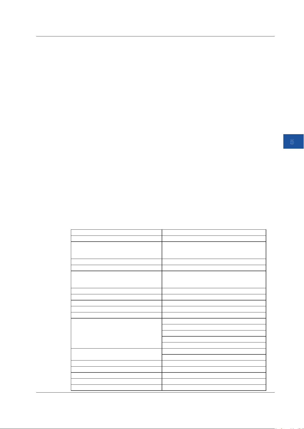
1
2
3
4
5.2 Saving Sweeps
CA550
For a step sweep, the same information as that explained in “Saving Data Manually” in Section 5.1
is saved in a single CSV file. If you abort a sweep, the data up to that point is saved.
For a program sweep, the same information as that explained in “Saving Data Manually” in Section
5.1 and the calibration target information are saved in a single CSV file. If you abort a sweep, the
data is not saved.
A total of up to 250 step sweep and program sweep files can be saved.
File Name
The following file name is automatically assigned.
Step sweep: YYYYMMDDhhmmss_xx.csv
YYYYMMDDhhmmss: year, month, day, hour, minute, and second
when the data entry was saved
YYYY: year, MM: month, DD: day, hh: hour, mm: minute, ss: second
xx: A sequence number starting from 00 that is assigned when the
save date and time overlaps
Program sweep: Tag No. + YYYYMMDDhhmm_xx.csv
YYYYMMDDhhmm: year, month, day, hour, and minute when the data
entry was saved
xx: A sequence number starting from 00 that is assigned when the
save date and time overlaps
5
Saving Data
Saved Information
The following information is saved.
Saving Data Using Step Sweep
Saved data Notes
MODEL CA550
FILE TYPE 0: Manually saved data using the SAVE key
1: Automatically saved data by a step sweep
2: Calibration data by a program sweep
CSV SEPARATOR 0: Comma, 1: Semicolon, 2: Tab
DECIMAL POINT 0: Period, 1: Comma
DATE FORMAT 0: YYYY/MM/DD
1: DD/MM/YYYY
2: MM/DD/YYYY
Range Measurement range, source range
0% VALUE
100% VALUE
DIVISION NUMBER (number of divisions)
CONTACT (contact I/O) 0: OFF, 1:ON
IM CA500-01EN
TC SETTING
(temperature setting)
FREQUENCY SETTING
(frequency setting)
No. Number
DATE Measurement date YYYY/MM/DD
TIME Measurement time hh:mm:ss
MEASURE Measurement value
SOURCE Source value
Thermocouple terminal setting. 0: TC-A, 1: TC-B
TC-B RJC setting. 0: OFF, 1:ON
Burnout setting. 0: OFF, 1:ON
TC scale standard setting. 0: ITS-90, 1:IPTS-68
Temperature unit. 0: °C
Amplitude voltage setting
Pulse count setting
5-5
Page 90

5.2 Saving Sweeps
Saving Data Using Program Sweep
Saved data Notes
MODEL CA550
FILE TYPE 0: Manually saved data using the SAVE key
CSV SEPARATOR 0: Comma, 1: Semicolon, 2: Tab
DECIMAL POINT 0: Period, 1: Comma
DATE FORMAT 0: YYYY/MM/DD
Range Measurement range, source range
0% VALUE
100% VALUE
CONTACT (contact I/O)
TC SETTING
(temperature setting)
FREQUENCY SETTING
(frequency setting)
MODEL NO. Model number
TAG NO. Tag number
SERIAL NO. Serial number
CALIBRATION DATE Calibration date
CALIBRATOR S/N CA550 serial number
No. Calibration point number
DATE Calibration date YYYY/MM/DD
TIME Calibration time of the calibration point hh:mm:ss
MEASURE Measurement value
SOURCE Source value
ERROR% Error
PASS/FAIL Pass/fail
1: Automatically saved data by a step sweep
2: Calibration data by a program sweep
1: DD/MM/YYYY
2: MM/DD/YYYY
0: OFF, 1:ON
Thermocouple terminal setting. 0: TC-A, 1: TC-B
TC-B RJC setting. 0: OFF, 1:ON
Burnout setting. 0: OFF, 1:ON
TC scale standard setting. 0: ITS-90, 1:IPTS-68
Temperature unit. 0: °C
Pulse count setting
YYYY/MM/DD
Errors and Pass/Fail Judgment
The instrument determines the error in the actual output value of the measured calibration target
relative to the output value (specified according to the specifications of the device to be calibrated)
that is mapped to the source value and saves it as a percentage.
The instrument judges pass or fail depending on whether the value is within the tolerance specified
in the SETUP menu of Function 1.
Proper judgment cannot be made unless the 0% or 100% measurement value of this instrument is
assigned to the output value (specified according to the specification of the device to be calibrated)
that is mapped to the 0% or 100% source value of this instrument.
5-6
IM CA500-01EN
Page 91
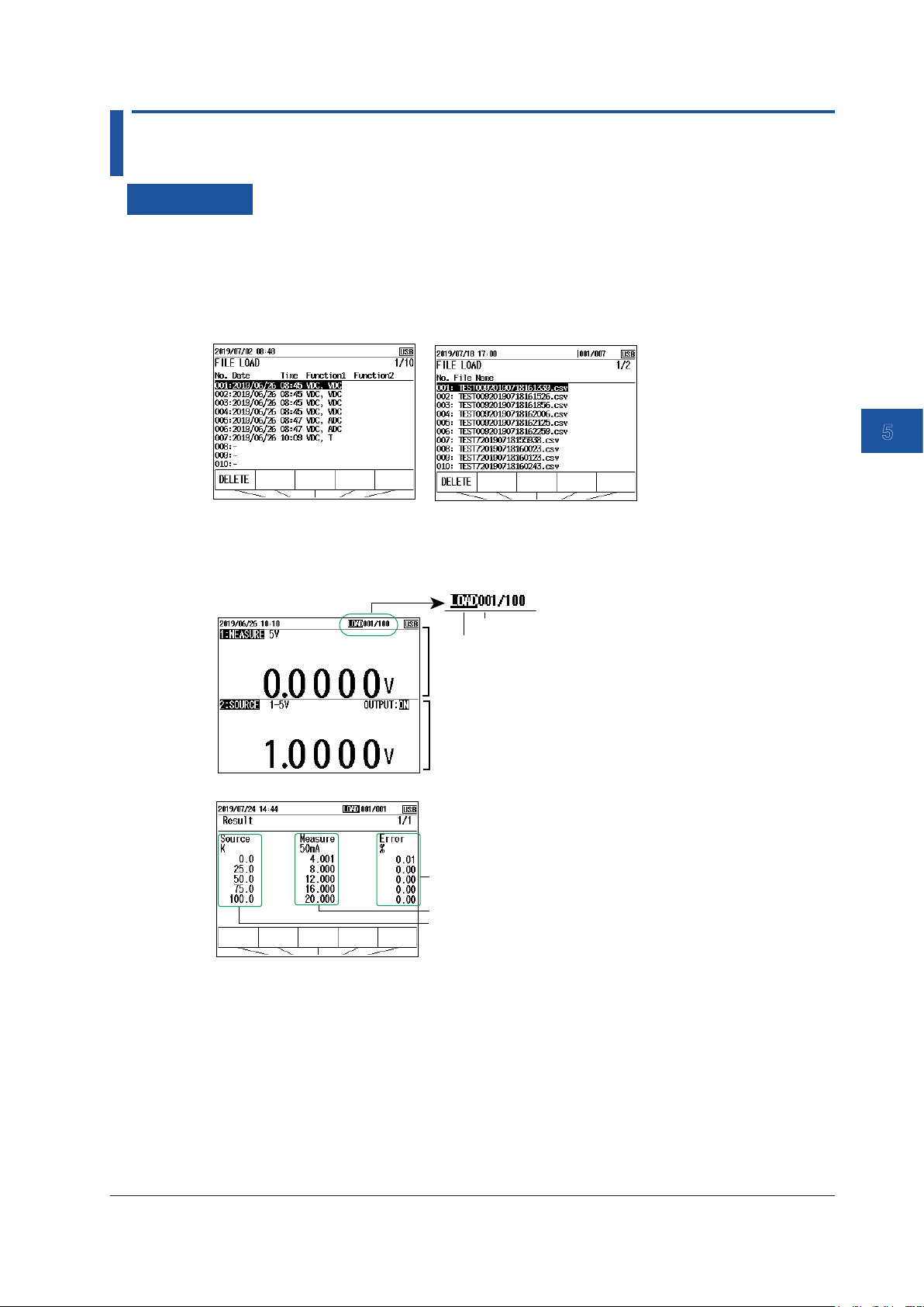
1
2
3
4
5.3 Loading and Deleting Saved Data
Procedure
1.
With the source value and measurement value displayed, press LOAD. A list of saved data is
displayed.
On the CA500, a list of data saved using the SAVE key is displayed. On the CA550, a list of
CSV files saved using program sweeps is displayed.
CA500
2.
Use the cursor keys to select the data you want to load, and then press ENTER.
The screen displays the loaded source value and measurement value (“LOAD” appears at the
top of the screen).
CA500
CA550
CA550
Memory number
LOAD is displayed on the load screen.
Function 1 data
Function 2 data
5
Saving Data
Error relative to the reference value
Measurement value of each step
The specified step in the program sweep
3.
Use the cursor keys to change the displayed data.
4.
On the CA500, when you press ENTER, the settings in the loaded file are applied to the
CA500.
5.
When you press ESC, the screen returns to the overview screen of step 1.
IM CA500-01EN
5-7
Page 92

5.3 Loading and Deleting Saved Data
Delete data.
1.
With the source value and measurement value displayed, press LOAD. A list of saved data is
displayed.
List of saved data
Deletes the selected data
2.
Use the cursor keys to select the data you want to delete, and then press DELETE. A
confirmation message appears.
3.
To delete, press ENTER. To cancel deleting, press ESC.
To delete data that cannot be loaded, format the internal memory (see section 6.7, “Formatting
(Initializing) the Internal Memory”).
Description
You can load saved data to view measurement values and source values and change the settings
according to the loaded data settings.
Data That Can Be Loaded
The following data can be loaded.
CA500: Data saved manually, data saved using step sweep or program sweep
CA550: File save using program sweep
Deleting Data
When the saved data or the number of files reaches the upper limit, data can no longer be saved. If
this occurs, you need to delete data or files.
Data saved on the CA500 or data saved automatically using the CA550 program sweep can be
deleted on the ROAD screen. To delete other types of data, format the internal memory.
5-8
IM CA500-01EN
Page 93

1
2
3
4
5.4 Copying Saved Data to a PC (CA550)
Procedure
1.
Connect this instrument to a PC through USB. This instrument is displayed as a USB storage
device on the PC.
2.
Copy the necessary data to the PC.
Description
CSV data saved on the CA550 can be copied to a PC.
Folder Structure
The following figure shows the CA550 folder structure.
Root
SaveData
Data saved with the SAVE key is saved.
5
Saving Data
SweepData
CalibrationData
Measurement/source data (.csv) of step
sweeps is saved.
Measurement/source data (.csv) of program
sweeps is saved.
Note
• Data cannot be written to or deleted from the CA500 internal memory from a PC.
• The CA550 internal memory information displayed on the PC is not updated automatically. To update the
information, remove the USB cable, or restart the CA550.
USB Interface Specifications
Electrical and mechanical specifications Complies with USB Rev.1.1
Connector Type B connector (receptacle)
Number of ports 1
Power supply Self powered, bus powered
PC system requirements A PC running Windows 8.1 or Windows 10 with a standard USB
port.
CDC(Communication Device Class)
This instrument uses CDC to communicate with a PC.
If the operating system of the PC connected to this instrument is Windows 8.1, you need to install a
CDC system definition file for YOKOGAWA products in the PC.
For details on how to obtain the system definition file, access the following YOKOGAWA’s webpage,
and download the file.
This is not necessary on Windows 10.
https://www.yokogawa.com/jp-ymi/tm/F-SOFT/
File name: YKCDC system definition file
IM CA500-01EN
5-9
Page 94

5.5 Saved Data Format (CA550)
The saved data (CSV) format on the CA550 is as follows:
Data Saved Using the SAVE Key
MODEL CA550
FILE TYPE 0
CSV SEPARATOR 0
DECIMAL POIINT 1
DATE FORMAT 0
RANGE 4-20mA Type-K
0%VALUE 4 0
100%VALUE 20 100
CONTACT 0 0
TC SETTING 0 0 1 0
FREQUENCY SETTING 1.0 0
No. DATE TIME FUNCTION2 FUNCTION1
1 xxxx/xx/xx xx:xx:xx ±xxx.xx ±xx.xxx
2 xxxx/xx/xx xx:xx:xx ±xxx.xx ±xx.xxx
3 xxxx/xx/xx xx:xx:xx ±xxx.xx ±xx.xxx
4 xxxx/xx/xx xx:xx:xx ±xxx.xx ±xx.xxx
Data Saved Using Step Sweep
MODEL CA550
FILE TYPE 2
CSV SEPARATOR 0
DECIMAL POIINT 1
DATE FORMAT 0
RANGE 4-20mA Type-K
0%VALUE 4 0
100%VALUE 20 100
CONTACT 0 0
TC SETTING 0 0 1 0
FREQUENCY SETTING 1.0 0
No. DATE TIME FUNCTION2 FUNCTION1
1 xxxx/xx/xx xx:xx:xx ±xxx.xx ±xx.xxx
2 xxxx/xx/xx xx:xx:xx ±xxx.xx ±xx.xxx
3 xxxx/xx/xx xx:xx:xx ±xxx.xx ±xx.xxx
4 xxxx/xx/xx xx:xx:xx ±xxx.xx ±xx.xxx
5 xxxx/xx/xx xx:xx:xx ±xxx.xx ±xx.xxx
6 xxxx/xx/xx xx:xx:xx ±xxx.xx ±xx.xxx
7 xxxx/xx/xx xx:xx:xx ±xxx.xx ±xx.xxx
8 xxxx/xx/xx xx:xx:xx ±xxx.xx ±xx.xxx
9 xxxx/xx/xx xx:xx:xx ±xxx.xx ±xx.xxx
10 xxxx/xx/xx xx:xx:xx ±xxx.xx ±xx.xxx
Function1 settings
Function2 settings
Measurement/source
value
5-10
IM CA500-01EN
Page 95

1
2
3
4
5.5 Saved Data Format (CA550)
Data Saved Using Program Sweep
MODEL CA550
FILE TYPE 2
CSV SEPARATOR 0
DECIMAL POIINT 1
DATE FORMAT 0
RANGE 4-20mA Type-K
0%VALUE 4 0
100%VALUE 20 100
CONTACT 0 0
TC SETTING 0 0 1 0
FREQUENCY SETTING 1.0 0
TAG NO TAG-01
SERIAL NO. 91Mxxyyyy
CALIBRATION DATE yyyy/mm/dd
CALIBRATOR S/N 91Mxxyyyy
No. DATE TIME FUNCTION2 FUNCTION1 ERROR% PASS/FAIL
1 xxxx/xx/xx xx:xx:xx ±xxx.xx ±xx.xxx ±xxx.xx PASS
2 xxxx/xx/xx xx:xx:xx ±xxx.xx ±xx.xxx ±xxx.xx PASS
3 xxxx/xx/xx xx:xx:xx ±xxx.xx ±xx.xxx ±xxx.xx PASS
4 xxxx/xx/xx xx:xx:xx ±xxx.xx ±xx.xxx ±xxx.xx PASS
5 xxxx/xx/xx xx:xx:xx ±xxx.xx ±xx.xxx ±xxx.xx FAIL
6 xxxx/xx/xx xx:xx:xx ±xxx.xx ±xx.xxx ±xxx.xx PASS
7 xxxx/xx/xx xx:xx:xx ±xxx.xx ±xx.xxx ±xxx.xx PASS
8 xxxx/xx/xx xx:xx:xx ±xxx.xx ±xx.xxx ±xxx.xx PASS
9 xxxx/xx/xx xx:xx:xx ±xxx.xx ±xx.xxx ±xxx.xx PASS
10 xxxx/xx/xx xx:xx:xx ±xxx.xx ±xx.xxx ±xxx.xx PASS
5
Saving Data
IM CA500-01EN
5-11
Page 96

1
2
3
4
5
Chapter 6 Other Features
6.1 Auto Power-off, Turning the Light Timer On and Off, and Turning the Light On and Off
Procedure
1.
With the source value and measurement value displayed, press MENU. A menu screen
appears.
2.
Use the cursor keys to select Device Setup, and then press ENTER. A Device Setup screen
appears.
Turn auto power-off on and off
3.
Use the cursor keys to select Auto Power Off. ON and OFF appear in the selection menu.
Turn auto power-off
on and off.
Turn the light timer
on or off.
6
Other Settings
4.
Use the arrow keys to select ON or OFF.
To finish entering the settings here, proceed to step 7.
Turning the Light Timer On and Off
5.
User cursor keys to select Light Timer. ON and OFF appear in the selection menu.
6.
Use the arrow keys to select ON or OFF
Confirming the Settings
7.
Press the arrow key corresponding to EXIT SETUP. The settings are confirmed, and a screen
appears showing the source value and measurement value.
Pressing ESC causes the instrument to discard the settings and return to the menu screen.
To initialize the settings, pressing the arrow key corresponding to INIT SETUP.
Turning the Light On and Off and Adjusting the Brightness
1.
Press on the instrument’s front panel. Each time you press the soft key, the setting toggles
between ON (dark), bright, and OFF.
IM CA500-01EN
6-1
Page 97

6.1 Auto Power-off, Turning the Light Timer On and Off, and Turning the Light On and Off
Description
Auto Power-off
Auto power-off is a function that automatically turns off the power when about 30 minutes elapses
after the last user interaction with the instrument.
Auto power-off is automatically disabled (the icon also disappears) in the following situations.
• Pulse count is in progress.
• The output is on.
• Sweeping is in progress.
• Power is being supplied through USB.
Light Timer
Light timer is a function that automatically turns off the screen light when about 10 minutes elapses
after the last user interaction with the instrument.
To turn the screen light on again, press the
key.
Turning the Light (screen light) On and Off
Using the key, you can turn the screen light on and off and change the brightness between two
levels.
Note
If the screen light is turned on in a dark location, white spots may appear on the screen.
This is due to the material characteristics of the light guide of the screen and has no effect on the
performance of the instrument.
6-2
IM CA500-01EN
Page 98

1
2
3
4
5
6.2 Turning Communication Resistance On or Off
Procedure
1.
With the source value and measurement value displayed, press MENU. A menu screen
appears.
2.
Use the cursor keys to select Device Setup, and then press ENTER. A Device Setup screen
appears.
3.
Use the cursor keys to select COM 250Ω. ON and OFF appear in the selection menu.
4.
Use the arrow keys to select ON or OFF
Other Settings
Confirming the Settings
6
5.
Press the arrow key corresponding to EXIT SETUP. The settings are confirmed, and a screen
appears showing the source value and measurement value.
Pressing ESC causes the instrument to discard the settings and return to the menu screen.
To initialize the settings, pressing the arrow key corresponding to INIT SETUP.
Description
When the communication resistance is turned on, a 250 Ω resistor is connected to the 24 V loop
power output inside the instrument. The communication resistance is used to provide amplitude
to the HART communication signals or BRAIN communication signals superimposed in the
transmission line.
Set this to off when communication signals are not superimposed in the transmission line.
IM CA500-01EN
6-3
Page 99

6.3 Setting the Priority Power Supply
Procedure
1.
With the source value and measurement value displayed, press MENU. A menu screen
appears.
2.
Use the cursor keys to select Device Setup, and then press ENTER. A Device Setup screen
appears.
3.
User cursor keys to select Power Select. USB (USB power supply) and BATT. (Batteries)
appear on the selection menu.
4.
Use the arrow keys to set the priority power supply.
Confirming the Settings
5.
Press the arrow key corresponding to EXIT SETUP. The settings are confirmed, and a screen
appears showing the source value and measurement value.
Pressing ESC causes the instrument to discard the settings and return to the menu screen.
To initialize the settings, pressing the arrow key corresponding to INIT SETUP.
Description
When batteries and USB power supply are both available for running the instrument, you can select
the power supply to prioritize.
If either the batteries or USB power supply becomes unavailable, a switch is made to the available
power supply.
6-4
IM CA500-01EN
Page 100
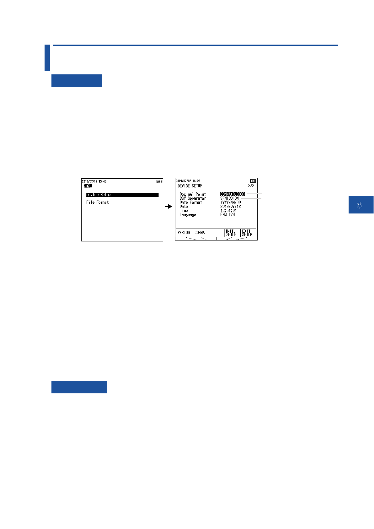
1
2
3
4
5
6.4 Setting the Decimal Symbol and CSV Separator
Procedure
1.
With the source value and measurement value displayed, press MENU. A menu screen
appears.
2.
Use the cursor keys to select Device Setup, and then press ENTER. A Device Setup screen
appears.
3.
Press the cursor keys several times to display Device Setup 2/2.
Decimal Symbol
4.
User cursor keys to select Decimal Point. PERIOD ( . ) and COMMA ( , ) appear on the
selection menu.
Set the decimal symbol.
Set the CSV separator.
6
Other Settings
5.
Use the arrow keys to set the symbol to use for the decimal point.
To finish entering the settings here, proceed to step 8.
CSV Separator
6.
Use the cursor keys to select CSV Separator. COMMA ( , ), SEMI COLON ( ; ) and TAB appear
on the selection menu.
7.
Use the cursor keys to set the symbol to use for the CSV separator.
Confirming the Settings
8.
Press the arrow key corresponding to EXIT SETUP. The settings are confirmed, and a screen
appears showing the source value and measurement value.
Pressing ESC causes the instrument to discard the settings and return to the menu screen.
To initialize the settings, pressing the arrow key corresponding to INIT SETUP.
Description
Set the decimal symbol and CSV separator that are used when saving the data sourced and
measured by this instrument.
Data can be saved according to the specifications of the software that the data will be used in.
IM CA500-01EN
6-5
 Loading...