

Page 1

User ’s
Manual
CA310 Volt mA Calibrator
CA320 TC Calibrator
CA330 RTD Calibrator
Getting Started Guide
IM CA310-02EN
3rd Edition
Page 2
Thank you for purchasing the CA310 Volt mA Calibrator, CA320 TC Calibrator, or CA330 RTD Calibrator. This operation guide focuses
on the handling precautions, basic operations, and specifications of the CA310/CA320/CA330.
To ensure correct use, please read this manual thoroughly before beginning operation. Keep this manual in a safe place for quick
reference in the event that a question arises.
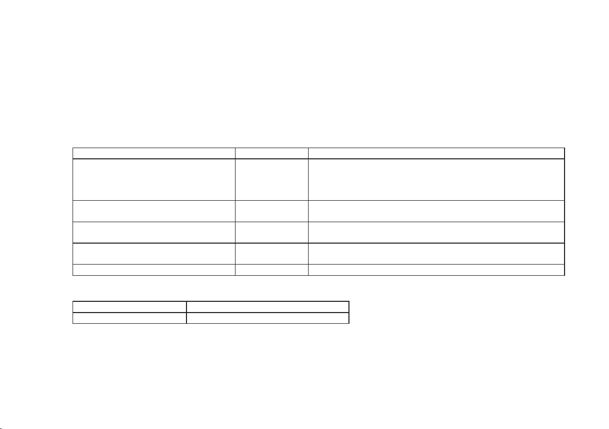
List of Manuals
The following five manuals, including this one, are provided as manuals for the CA310/CA320/CA330.
Please read all manuals.
Manual Title Manual No. Description
CA310 Volt mA Calibrator
CA320 TC Calibrator
CA330 RTD Calibrator
Getting Started Guide
CA310 Volt mA Calibrator
User’s Manual
CA320 TC Calibrator
User’s Manual
CA330 RTD Calibrator
User’s Manual
CA310/CA320/CA330 User’s Manual IM CA310-92Z1 For China
Contact information of Yokogawa offices worldwide is provided on the following sheet.
Manual No. Description
PIM113-01Z2 List of worldwide contacts
IM CA310-02EN This guide. The guide explains the handling precautions and basic
operations of the CA310/CA320/CA330 and provides a list of
specifications.
IM 310-01Z2 This manual explains how to use CA310.
IM 320-01Z2 This manual explains how to use CA320.
IM 330-01Z2 This manual explains how to use CA330.
3rd Edition: October 2017 (YMI)
All Rights Reserved, Copyright © 2015, Yokogawa Test & Measurement Corporation
Printed in Japan
IM CA310-02EN
1
Page 3

Notes
• The contents of this manual are subject to change without prior notice as a result of continuing improvements to the instrument’s
performance and functionality. The figures given in this manual may differ from those that actually appear on your screen.
• Every effort has been made in the preparation of this manual to ensure the accuracy of its contents. However, should you have any
questions or find any errors, please contact your nearest YOKOGAWA dealer.
• Copying or reproducing all or any part of the contents of this manual without the permission of YOKOGAWA is strictly prohibited.
Trademarks
• Adobe, Acrobat, and PostScript are either registered trademarks or trademarks of Adobe Systems Incorporated.
• In this manual, the ® and TM symbols do not accompany their respective registered trademark or trademark names.
• Other company and product names are trademarks or registered trademarks of their respective companies.
Revisions
November 2015 1st Edition
October 2016 2nd Edition
October 2017 3rd Edition
2
IM CA310-02EN
Page 4

Product Registration
Thank you for purchasing YOKOGAWA products.
YOKOGAWA provides registered users with a variety of information and services.
Please allow us to serve you best by completing the product registration form accessible from our
homepage.
IM CA310-02EN
http://tmi.yokogawa.com/
3
Page 5

Checking the Contents of the Package
Unpack the box and check the contents before operating the instrument. If the wrong items have been delivered, if items are missing, or
if there is a problem with the appearance of the items, contact your nearest YOKOGAWA dealer.
CA310/CA320/CA330
Check that the product that you received is what you ordered by referring to the model name on the name plate on the rear panel of the
main unit. For reference, the model name and specifications of the products are listed below.
Model Suffix Code Specifications
CA310 Volt mA Calibrator
CA320 TC Calibrator
CA330 RTD Calibrator
For products whose suffix code contains “Z,” an exclusive manual may be included. Please read it along with the standard manual.
4
IM CA310-02EN
Page 6
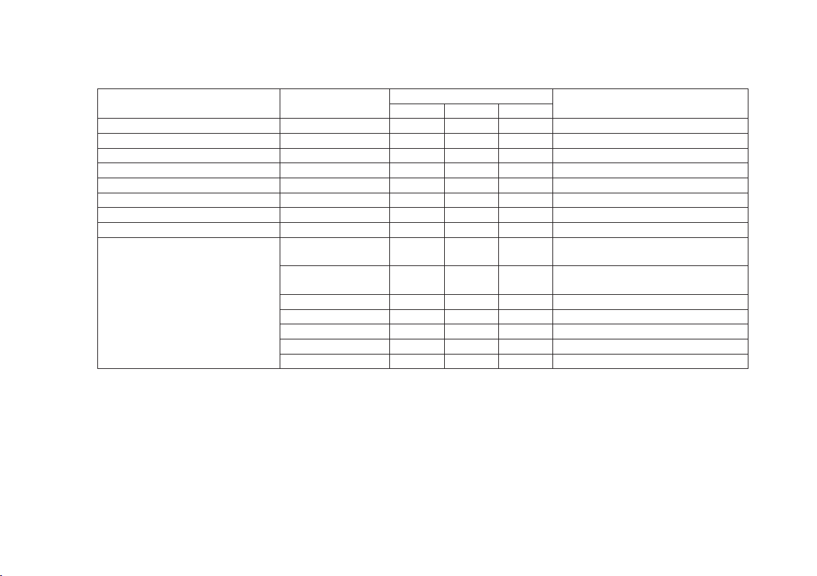
Standard Accessories
The following accessories are included. Make sure that all accessories are present and undamaged.
Item
Lead cable 98064 1 — — For the CA310 1 red, 1 black
Lead cable 98040 — 1 — For the CA320 1 red, 1 black
Lead cable 98035 — — 1 For the CA330 3 red, 1 black
Binding post (red-black pair) 99045 — 1 1 One short plate included
Binding post (red-red pair) 99046 — — 1 One short plate included
Batteries — 4 4 4 AA alkaline batteries (LR6)
Portable case B9108NK 1 1 1
Antiskid rubber — 1 1 1 Antiskid rubber for the bottom panel
Manuals IM CA310-02EN 1 1 1 Getting Started Guide
* Standard accessories are not covered by warranty of this instrument.
Model or
Component Number
IM CA310-02JA 1 1 1 Japanese manual
IM CA310-02Z2 1 — — User’s manual for the CA310
IM CA320-02Z2 — 1 — User’s manual for the CA320
IM CA330-02Z2 — — 1 User’s manual for the CA330
IM CA310-92Z1 1 1 1 Document for China
PIM 113-01Z2 1 1 1 List of contacts
CA310 CA320 CA330
Quantity
Notes
For CA310, CA320, and CA330
For CA310, CA320, and CA330
IM CA310-02EN
5
Page 7
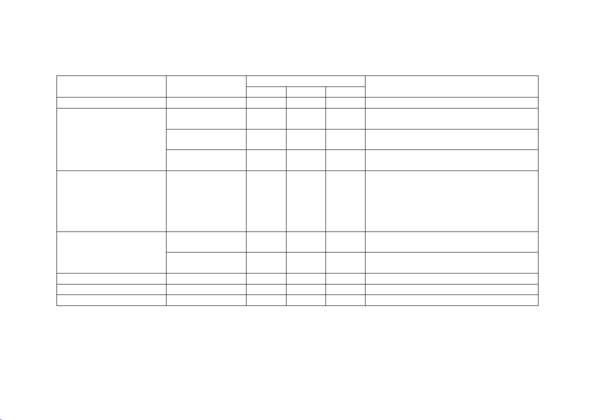
Optional Accessories (Sold separately)
The following optional accessories are available for purchase separately. For information about ordering accessories, contact your
nearest YOKOGAWA dealer.
Model or
Component Number
93060
Rubber boots
Item
1
AC adapter 94012
94013
94016
RJ sensor 90080 —
TC mini plug set 90040 —
90045 —
Grabber clip 98025
Strap 97040
Accessory case B9108XA
* Optional accesories(sold separately) are not covered by warranty of this instrument.
1 When rubber boots are attached, the CA310/CA320/CA330 cannot be stored in the portable case.
2 Cannot be used simultaneously with the included binding post (99045/99046).
Applicable To
CA310 CA320 CA330
P P P
P P P
P P P
P P P
P P
P
P
P
2
— PT100 JIS AA class or equivalent
— 10 types
— 4 types
2
P
P P P
P P P
Notes
For protecting the main unit
Input:100 VAC
Operating temperature range: -10°C to 40°C
Input:120 VAC
Operating temperature range: -10°C to 40°C
Input: 220 VAC
Operating temperature range: -10°C to 40°C
Thermometer operating temperature range:
-10°C to 55°C
8-polar miniDin connector
Shielded cable 1.5 m
Y terminal (compatible with M3 terminal blocks)
K/T/J/E/R(S)/G/C/D/N/B(U)
K/T/J/E
Red-black pair, separate type (2 m)
For rubber boots
6
IM CA310-02EN
Page 8
Safety Precautions
This product is designed to be used by a person with specialized knowledge.
The general safety precautions described herein must be observed during all phases of operation. If the product is used in a manner
not specified in this guide, the protection provided by the product may be impaired. YOKOGAWA assumes no liability for the customer’s
failure to comply with these requirements.
This manual is part of the product and contains important information. Store this manual in a safe place close to the instrument so that
you can refer to it immediately. Keep this manual until you dispose of the instrument.
IM CA310-02EN
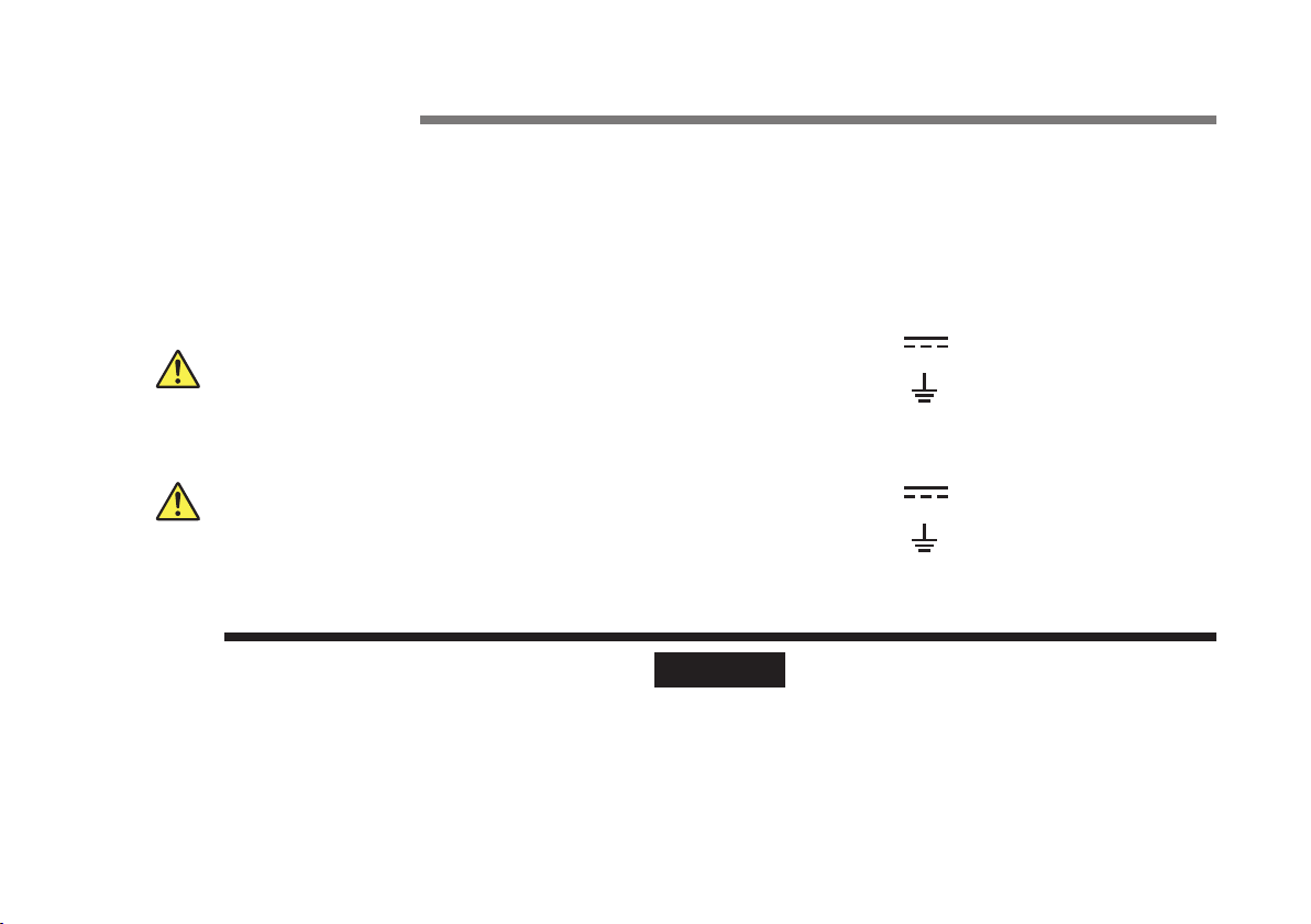
The following symbols are used on this instrument.
Warning: handle with care. Refer to the user’s manual or service manual.
This symbol appears on dangerous locations on the meter which require
special instructions for proper handling or use. The same symbol appears in
the corresponding place in the manual to identify those instructions.
Direct current
Functional ground
French
Avertissement : À manipuler délicatement. Toujours se reporter aux manuels
d’utilisation et d’entretien. Ce symbole a été apposé aux endroits dangereux
de l’instrument pour lesquels des consignes spéciales d’utilisation ou
de manipulation ont été émises. Le même symbole apparaît à l’endroit
correspondant du manuel pour identifier les consignes qui s’y rapportent.
Courant direct
Borne de terre fonctionnelle
Failure to comply with the precautions below could lead to injury or death or damage to the instrument.
WARNING
Use the Instrument Only for Its Intended Purpose
This instrument is a calibrator for the voltage/current measuring instrument (CA310), thermocouple/measuring
instrument (CA320), and RTD/measuring instrument (CA330). Use this instrument only as a calibrator.
Check the Physical Appearance
Do not use the instrument if there is a problem with its physical appearance.
7
Page 9

AC adapter
Only use the dedicated AC adapter for the instrument.
Batteries
• Do not mix new and old batteries or mix different brands or types of batteries. The batteries may leak, heat up, or
burst due to their characteristic differences.
• Never replace the batteries while measurement is in progress.
Do Not Operate in an Explosive Atmosphere
Do not use this instrument in the presence of flammable gases or vapors. Doing so is extremely dangerous.
Do Not Remove Covers or Disassemble or Alter the Instrument
Only qualified YOKOGAWA personnel may remove the covers and disassemble or alter the instrument.
Measurement Category
The measurement category of this instrument’s signal input terminals is Other (O). Do not use it to measure the main
power supply or for Measurement Categories II, III, and IV.
Install or Use the Instrument in Appropriate Locations
• Do not install the instrument outdoors or in locations subject to rain or water. Or, use the instrument in such locations.
• Install the instrument so that you can immediately turn off the power if an abnormal or dangerous condition occurs.
Wiring
• Be sure to use the included lead cables.
• The maximum voltage application between all I/O terminals and earth is 50 VDC (measurement terminal of CA310)
or 42 VDC (other than the measurement terminal of CA310). Do not apply voltages that exceed 50 VDC or 42 VDC .
Doing so may cause electric shock or burns or may damage the instrument.
• Always turn off the power of the device under measurement before connecting it. Connecting or disconnecting lead
cables without turning off the device under measurement is extremely dangerous.
• Do not connect current circuits to the CA310 voltage input terminal. Likewise, do not connect voltage circuits to the
current input terminal. Improper connection may cause electric shock or burns or may damage the device under
measurement or the instrument.
• Do not apply currents that exceed the maximum allowable input current to the CA310 current input terminal.
8
IM CA310-02EN
Page 10

CAUTION
Operating Environment Limitations
This product is a Class A (for industrial environment) product. Operation of this product in a residential area may cause
radio interference in which case the user will be required to correct the interference.
French
AVERTISSEMENT
Ne faites de cet équipement que l’utilisation pour laquelle il a été conçu
Cet équipement est un calibreur pour l’équipement de mesure de tension/courant (CA310), pour l’équipement de
termocouple/mesure (CA320) et pour l’équipement de RTD/mesure (CA330). Utilisez cet équipement à des fins de
calibrage uniquement.
Inspecter l’apparence physique
Ne pas utiliser l’instrument si son intégrité physique semble être compromise.
Adaptateur c.a.
Utiliser exclusivement l’adaptateur c.a. dédié pour l’instrument.
Batteries
• Ne pas mélanger des batteries neuves et des batteries usagées, ni des batteries de marques ou de types différents.
Les batteries risquent de fuir, de chauffer ou d’éclater en raison de leurs différentes caractéristiques.
• Ne jamais remplacer les batteries lorsque la mesure est en cours.
Ne pas utiliser dans un environnement explosif
Ne pas utiliser l’instrument en présence de gaz ou de vapeurs inflammables. Cela pourrait être extrêmement
dangereux.
Ne pas retirer le capot, ni démonter ou modifier l’instrument
Seul le personnel YOKOGAWA qualifié est habilité à retirer le capot et à démonter ou modifier l’instrument.
IM CA310-02EN
9
Page 11

Catégorie de mesure
La catégorie de mesure des terminaux d’entrée de signal du CA310, CA320, CA330 est Autre(O). Ne pas l’utiliser pour
mesurer l’alimentation électrique, ni pour les catégories de mesureII, III et IV.
Installer et utiliser l’instrument aux emplacements appropriés
• Ne pas installer, ni utiliser l’instrument à l’extérieur ou dans des lieux exposés à la pluie ou à l’eau.
• Installer l’instrument de manière à pourvoir immédiatement le débrancher du secteur en cas de fonctionnement
anormal ou dangereux.
Câblage
• Veillez à utiliser tous les câbles fournis.
• La tension maximum autorisée entre toutes les bornes I/O et la terre est de 50 V c.c. (borne mesure du CA310) ou
de 42 V c.c. (autre que la borne de mesure du CA310). N’appliquez pas de tension supérieure à 50 V c.c (CA310) ou
à 42 V c.c (CA320/CA330). Le cas échéant vous vous exposeriez à des risques de choc électrique ou de brûlure ou
vous risqueriez d’endommager l’équipement.
• Mettez toujours le dispositif à mesurer hors tension avant de le connecter à l’équipement. Il est extrêmement
dangereux de brancher ou débrancher des câbles sans avoir préalablement mis le dispositif à mesurer hors tension.
• Ne branchez pas de circuits de courant sur la borne d’entrée de tension du CA310. Ne branchez pas non plus de
circuits sous tension sur la borne d’entrée de courant. Un branchement incorrect vous exposerait à des risques de
choc électrique ou de brûlure, ou risquerait d’endommager l’appareil à mesurer ou l’équipement.
• N’appliquez pas de courant supérieur au courant d’entrée maximum admissible à la borne d’entrée de courant du
CA310.
ATTENTION
Limitations relatives à l’environnement opérationnel
Ce produit est un produit de classe A (pour environnements industriels). L’utilisation de ce produit dans un zone
résidentielle peut entraîner une interférence radio que l’utilisateur sera tenu de rectifier.
10
IM CA310-02EN
Page 12

Conventions Used in This Guide
Notes
The notes and cautions in this guide are categorized using the following symbols.
Improper handling or use can lead to injury to the user or damage to the instrument. This symbol appears
on the instrument to indicate that the user must refer to the manual for special instructions. The same
symbol appears in the corresponding place in the manual to identify those instructions. In the manual, the
symbol is used in conjunction with the word “WARNING” or “CAUTION.”
IM CA310-02EN
WARNING
Calls attention to actions or conditions that could cause serious or fatal injury to the user, and precautions
that can be taken to prevent such occurrences.
French
AVERTISSEMENT
CAUTION
Attire l’attention sur des gestes ou des conditions susceptibles de provoquer des blessures graves (voire
mortelles), et sur les précautions de sécurité pouvant prévenir de tels accidents.
Calls attention to actions or conditions that could cause light injury to the user or damage to the instrument
or user’s data, and precautions that can be taken to prevent such occurrences.
French
ATTENTION
Note
Attire l’attention sur des gestes ou des conditions susceptibles de provoquer des blessures légères ou
d’endommager l’instrument ou les données de l’utilisateur, et sur les précautions de sécurité susceptibles
de prévenir de tels accidents.
Calls attention to information that is important for the proper operation of the instrument.
11
Page 13
Waste Electrical and Electronic Equipment (WEEE), Directive
(This directive is valid only in the EU.)
This product complies with the WEEE directive marking requirement. This marking indicates that you must not discard this
electrical/electronic product in domestic household waste.
Product Category
With reference to the equipment types in the WEEE directive, this product is classified as a “Monitoring and control instruments”
product. When disposing products in the EU, contact your local Yokogawa Europe B.V. office. Do not dispose in domestic
household waste.
EU Battery Directive
(This directive is valid only in the EU.)
Batteries are included in this product. This marking indicates they shall be sorted out and collected as ordained in the EU battery
directive.
Battery type:
Alkaline
When disposing of alkaline batteries, follow the domestic law concerning disposal. Take the proper action to dispose
batteries in accordance with the established collection system in the European Economic Area. For the battery removal
procedure, see page 26.
Authorized Representative in the EEA
Yokogawa Europe B.V. is the authorized representative of Yokogawa Test & Measurement Corporation for this product in the EEA. To
contact Yokogawa Europe B.V., see the separate list of worldwide contacts, PIM 113-01Z2.
12
IM CA310-02EN
Page 14

Contents
Product Registration ................................................................3
Checking the Contents of the Package ...................................4
Safety Precautions ..................................................................7
Conventions Used in This Guide ...........................................11
Waste Electrical and Electronic Equipment (WEEE),
Directive ................................................................................12
EU Battery Directive ..............................................................12
Authorized Representative in the EEA ..................................12
Names and Functions of Parts ...........................14
Front Panel, Side Panel, and Rear Panel .............................14
Keys ......................................................................................15
Display ..................................................................................17
Making Preparations for Measurements ............18
Handling Precautions ............................................................18
Installing the Instrument ........................................................20
Connecting Cables ................................................................23
Using Thermocouple Mini Plugs (CA320 only) .....................25
Installing and Removing Batteries .........................................26
Connecting the AC Adapter ................................................... 27
Turning the Power On and Off ..............................................28
Common Operations ...........................................29
Troubleshooting, Maintenance, and
Inspection
Troubleshooting ....................................................................32
Recommended Replacement Parts, Consumable Parts, and
Calibration .............................................................................33
Disposing of the Instrument ..................................................33
.............................................................32
Specifications .......................................................34
CA310 ...................................................................................34
CA320 ...................................................................................36
CA330 ...................................................................................46
Common Specifications ........................................................49
External Dimensions .............................................................51
IM CA310-02EN
13
Page 15
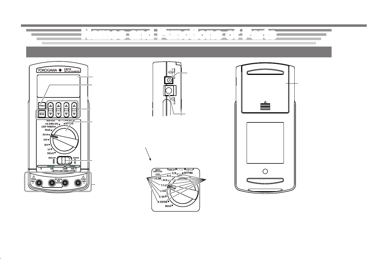
Names and Functions of Parts
Battery cover
Front Panel, Side Panel, and Rear Panel
CA310 example
14
Display
POWER key
Turns the power on
and off.
Keys
Rotary switch
Selects the range and
sensor type. You can
also select the setup
mode (SETTING).
Measurement/
source switch
TYPE1
I/O terminals
CA320
AC adapter jack
Connect the AC
adapter, an
accessory sold
separately.
RJ sensor
connector
(CA320 only)
Connect an RJ
sensor.
TYPE2
IM CA310-02EN
Page 16
Source
CA310
CA320/
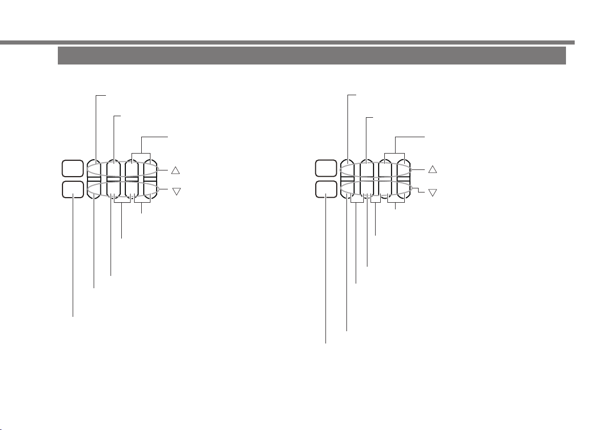
Names and Functions of Parts
Keys
Set the output to 100% in span check.
Set to 0% when sweeping is stopped or paused.
Increases the output span by 25% in span
check.
Press simultaneously during
normal output to set the display
span to 100%.
▲▲▲▲▲▲▲
POWER
OUTPUT
ON/OFF
key
Increases the number
▲
key
Decreases the number
Press simultaneously during normal
output to set the display span to 0 %.
Press simultaneously to switch between
normal output, span check, step sweep, and
linear sweep.
Decreases the output span by 25% in span check.
Pauses or resumes sweeping in sweep mode.
Set the output to 0% in span check.
OUTPUT ON/OFF key
Turns the output on and off Starts or
stops sweeping in sweep mode.
CA330
Set to 0% when sweeping is stopped or paused.
Increases the output span by 25% in span
Set the output to 100% in span check.
check.
Press simultaneously during
normal output to set the display
span to 0%.
▲▲▲▲▲▲▲
POWER
TYPE
▲
key
Increases the number
key
Decreases the number
Press simultaneously during normal
output to set the display span to 100 %.
Press simultaneously to switch between
normal output, span check, step sweep, and
linear sweep.
Decreases the output span by 25% in span check.
Press simultaneously to switch the sub display item
(voltage corresponding to temperature (CA320) or
resistance (CA330), span % display, RJ sensor
temperature (CA320)).
Set the output to 0% in span check.
TYPE key
Select the sensor.
Stops or resumes sweeping in sweep mode.
IM CA310-02EN
15
Page 17

CA310
CA320/CA330
Press simultaneously to switch the sub display item
Names and Functions of Parts
Measurement
▲▲▲▲▲▲▲
POWER
OUTPUT
ON/OFF
▲
OUTPUT ON/OFF key
Turns LOOP POWER on and off if
LOOP POWER is in use.
▲▲▲▲▲▲▲
POWER
TYPE
▲
(voltage corresponding to temperature, span %
display, RJ sensor temperature (CA320)).
On the CA330, select the wiring system from 2W
(two-wire), 3W (three-sire), and 4W (four-wire).
TYPE key
Select the sensor.
16
IM CA310-02EN
Page 18

11
CA310
CA320
IM CA310-02EN
2
8
16
CA330
Names and Functions of Parts
Display
No. Description
1 Appears in measurement mode
2 Appears in source mode
3 Battery level
4 Appears during sourcing (blinks when sweeping is paused)
5 Appears when the HART/BRAIN communication resistor is
enabled*
6 Sub display. Displays options in setup mode.
7 Sub display unit
8 Output method
Normal output (outputs the specified value): not
displayed
Span check (manual step): SPAN
Step sweep:
Linear sweep:
9 Main display unit
10 Calibration mode (not displayed normally)
11 Appears when auto power off is enabled
12 Main display
13 Selection status of the TC connection terminal
When the thermocouple mini plug terminal is in use: A
When the banana terminal is in use: B
14 RJ sensor setup mode
RJ sensor off: not displayed
When internal RJ sensor is set: RJ
When external RJ sensor is set: EXT RJ
15 Appears when the temperature standard is set to IPTS-68
16 Sensor selection status based on the TYPE key
Wiring system. Two-wire: 2W, three-wire: 3W, four-wire: 4W
17
* Appears only for LOOP POWER even when it is set to ON.
17
6
7
9
10
15
3 4 5
1
12
13 14
17
Page 19

Making Preparations for Measurements
Handling Precautions
Safety Precautions
If you are using this instrument for the first time, make sure to thoroughly read “Safety Precautions,” on pages 7 to 10.
Unplug If Abnormal Behavior Occurs
If you notice smoke or unusual odors coming from the instrument, immediately turn off the power, remove the batteries if possible, and
contact your nearest YOKOGAWA dealer.
General Handling Precautions
Do Not Place Objects on Top of the Instrument
Never place objects such as other instruments or objects that contain water on top of the instrument. Doing so may damage the
instrument.
Do Not Subject the Inputs and Outputs to Mechanical Shock
If the I/O connectors or adapters are subjected to mechanical shock, they may be damaged. The instrument may not perform
measurements correctly due to damage or deformation that is not visible to the naked eye.
Do Not Scratch the LCD
Because the LCD can be easily scratched, do not allow any sharp objects near it. Also, do not apply vibration or shock to it. Furthermore,
do not apply strong shock to the LCD or place objects on top of it.
Remove the Batteries during Extended Non-Use
Remove the batteries from the main unit. Remove the AC adapter power cord from the outlet.
When Carrying the Instrument
Remove the power cord and connecting cables.
When Cleaning the Instrument
When cleaning the case or the operation panel, gently wipe the outer surface using a damp, well-wrung, soft, clean cloth. The instrument
can malfunction if water enters inside the instrument.
Do not use chemicals such as benzene or thinner. Doing so may cause discoloring and deformation.
18
IM CA310-02EN
Page 20

Making Preparations for Measurements
Other Precautions
• Keep electrically charged objects away from the input terminals. They may damage the internal circuitry.
• Do not cover the case or operation panel with a volatile material or leave rubber or vinyl products in contact with the case or operation
panel for a long time.
Storage Precautions
Avoid the following kinds of places for storing the instrument:
• Where the temperature falls outside the storage temperature and humidity ranges
• In direct sunlight or near heat sources
• In an environment with excessive amounts of soot, steam, dust, or corrosive gas
• In an environment subject to large levels of mechanical vibration
• On an unstable surface
• Where an excessive amount of soot, dust, salt, or iron is present
IM CA310-02EN
19
Page 21

Making Preparations for Measurements
Installing the Instrument
WARNING
• Install the instrument so that you can immediately turn off the power if an abnormal or dangerous condition occurs.
• Do not use the instrument to measure locations that fall under Measurement Categories II, III, and IV.
CAUTION
This instrument is equipped with voltage and current source and measurement features. Do not use the instrument
when it is wet. Doing so may damage the instrument.
French
AVERTISSEMENT
• Installer l’instrument de manière à pourvoir immédiatement le débrancher du secteur en cas de fonctionnement
anormal ou dangereux.
• N’utilisez pas cet équipement pour mesurer des points tombant sous les catégories de mesure II, III et IV.
ATTENTION
Cet équipement est doté de fonctions de mesure et de source de courant et de tension. N’utilisez pas l’équipement
lorsqu’il est mouillé. Le cas échéant, un endommagement de l’équipement risquerait de se produire.
20
IM CA310-02EN
Page 22

Making Preparations for Measurements
Installation Conditions
Install the instrument in a place that meets the following conditions.
• Operating Altitude and Ambient Temperature and Humidity
• Use the instrument in the following environment.
• Ambient temperature: –10°C to 55°C
• Ambient humidity: 20% RH to 80% RH; no condensation
• Operating altitude: 2000 m or less
Note
• To ensure accurate use, operate the instrument within 23°C ± 5°C.
• When using the instrument in a place where the ambient humidity is 30% or less, take measures to prevent static electricity such as
using an anti-static mat.
• Condensation may occur if the instrument is moved to another place where the ambient temperature or humidity is higher, or if the
temperature changes rapidly.
In such cases, before you use the instrument, allow it to adjust to the surrounding temperature for at least an hour.
Do not install the instrument in the following places.
• In direct sunlight or near heat sources
• In an environment with excessive amounts of soot, steam, dust, or corrosive gas
• Near strong magnetic field sources
• Near noise sources, such as high-voltage equipment or power lines
• In an environment subject to large levels of mechanical vibration
• On an unstable surface
• In an environment where ignition or explosion may occur, such as in explosive gas
IM CA310-02EN
21
Page 23

Antiskid rubber
Making Preparations for Measurements
Measurement Category
The measurement category of this instrument is Other (O).
Measurement Category Description Notes
O(None, Other) Other circuits that are not directly connected to the
mains.
CAT II For measurements performed on circuits that are
connected to low-voltage installations
Circuits that are not powered from the
mains
Household appliances, portable tools,
etc.
CAT III For measuring facility circuits Distribution boards, circuit breakers, etc.
CAT IV For measurements performed on power source
Entrance cables, cable systems, etc.
circuits
Portable Case and Antiskid Rubber
How to Use the Portable Case
Unfasten the hook on the strap end and hooks on the sides of the case cover, and open the cover.
1.
Rotate the case 180° around the hook on the company logo end of the case.
2.
The hook on the company logo end cannot be unfastened.
Overlap the case cover over the bottom of the case, and fasten the hook on the strap end and hooks on the sides of the case cover.
3.
Antiskid rubber
Affix the included antiskid rubber to the location indicated in the following figure.
22
(included)
IM CA310-02EN
Page 24

Connecting Cables
500 mV, 5 V, 30 V, or 50 V range
20 mA or 50 mA range
LOOP POWER
20 mA range mA SIMULATE
DC voltage measurement circuit DC current measurement circuit
500 mV, 5 V, or 30 V range
To connect the CA310, use the included lead cable.
CA310 (measurement)
DC voltage source DC current source
CA310 (source)
Making Preparations for Measurements
– +
Two-wire
transmitter
Hart Communicator
IM CA310-02EN
V
A
– +
Distributor
23
Page 25

CA320 (measurement)
CA320 (source)
included with the CA320, remove the
* The Lo banana terminal and the Lo thermocouple mini plug terminal are shorted internally.
CA330 (measurement 4 W)
CA330 (source)
CA330 (measurement 3 W)
CA330 (measurement 2 W)
(Lo)
(Hi)
(Hi)
(Lo)
Making Preparations for Measurements
Thermocouple mini plug terminal
TC
SENSE
INPUT
(Hi)
(Hi)
4W
Short bar
SEMSE
INPUT
Banana terminal
TC
SEMSE
INPUT
(Lo)
(Lo)
RTD
(Lo)(Hi)
3W
Short bar
Thermocouple mini plug terminal
Thermocouple measurement circuit for temperature
transmitter, temperature converter, etc.
SENSE
(Hi)
Example of using a binding post
Attach according to the terminal color.
INPUT
Resistance measurement terminal of temperature
transmitter, temperature converter, etc.
SEMSE
V
INPUT
(Hi)
RTD
V
SEMSE
INPUT
(Lo)
(Lo)
Example of using a binding post
Attach according to the terminal color.
*: Before using the binding post
short bar from the binding post.
SENSE
(Hi)
INPUT
(Hi)
INPUT
(Lo)
RTD
*
SEMSE
(Lo)
24
IM CA310-02EN
Page 26

Making Preparations for Measurements
Using Thermocouple Mini Plugs (CA320 only)
The CA320’s terminal A is a dedicated thermocouple mini plug terminal.
Using a thermocouple mini plug enables higher accuracy and more stable thermocouple measurement and sourcing than a banana
terminal.
Use the same type of thermocouple mini plug as the plug on the item to be calibrated (thermocouple or range of the device to be
calibrated).
(Use the thermocouple mini plug set 90040 or 90045 or a thermocouple mini plug that you prepared.)
To connect the plug and the item to be calibrated, use the same type of thermocouple or compensating lead wire as that used on the
item to be calibrated. (Prepare your own thermocouple or compensating lead wires.)
When terminal A is in use, reference junction compensation based on the internal temperature sensor is applied.
IM CA310-02EN
25
Page 27

Making Preparations for Measurements
Installing and Removing Batteries
WARNING
• Do not remove the batteries with the main unit turned on.
• Never replace the batteries while measurement is in progress.
• Insert batteries with the correct polarity. Otherwise, the batteries may leak, heat up, or burst.
• Do not mix new and old batteries or mix different brands or types of batteries. The batteries may leak, heat up, or burst
due to their characteristic differences.
• When replacing batteries, be sure to remove the lead cables.
French
AVERTISSEMENT
• Ne retirez pas les piles lorsque le boîtier principal est en marche.
• Ne jamais remplacer les batteries lorsque la mesure est en cours.
• Inserer les batteries en observant la polarite correcte. A defaut, les batteries risquent de fuir, de chauffer ou d’eclater.
• Ne pas mélanger des batteries neuves et des batteries usagées, ni des batteries de marques ou de types différents.
Les batteries risquent de fuir, de chauffer ou d’éclater en raison de leurs différentes caractéristiques.
• Lors du remplacement des batteries, veillez a retirer les cables de plomb.
Turn the power off.
1.
Push the battery cover on the rear panel in the direction of the arrow, and open the cover.
2.
Remove the old batteries, and insert new batteries with the correct polarities.
3.
Attach the battery cover. Close the cover completely until you hear a click.
4.
26
IM CA310-02EN
Page 28

Connecting the AC Adapter
WARNING
• Do not connect or remove the AC adapter with the main unit turned on.
• Only use the dedicated AC adapter for the instrument.
• Do not place objects on top of the AC adapter or power cord, and keep them away from heat sources. When removing
the plug from the power outlet, do not pull on the cord. Pull from the plug.
• For details on handling the AC adapter, follow the instruction manual of the AC adapter.
French
AVERTISSEMENT
• Ne branchez pas ni ne débranchez l’adaptateur c.a. lorsque le boîtier principal est en marche.
• Utiliser uniquement l’adaptateur de CA dédié et le câble d’alimentation de cet instrument.
• Ne posez pas d’objets sur l’adaptateur c.a. ni sur le cordon d’alimentation, et maintenez ces derniers à l’écart de toute
source de chaleur. Ne tirez pas sur le cordon d’alimentation lorsque vous débranchez la prise de la source d’alimentation.
Tirez sur la prise.
• Pour des détails sur l’utilisation de l’adaptateur c.a., consultez le mode d’emploi de l’adaptateur c.a.
Turn the power off.
1.
Connect the AC adapter’s DC cable to the AC adapter jack on the instrument’s side panel.
2.
Connect the AC adapter to an AC power supply.
3.
Making Preparations for Measurements
IM CA310-02EN
27
Page 29

Making Preparations for Measurements
Turning the Power On and Off
Before Turning On the Power, Check That:
• The instrument is installed properly. See “Installing the Instrument.”
• The batteries are inserted properly. See “Installing and Removing Batteries.”
Turning the Power On
1. Hold down the POWER key on the front panel.
Power-On Operation
When the power is turned on, a memory check starts automatically.
If the instrument does not power on properly, turn the power off, and check that:
• The dry cells are inserted properly.
• New and old dry cells are not being used together.
• Batteries of different types or different brands are being used together.
If the instrument still does not work properly, contact your nearest YOKOGAWA dealer for repairs.
Turning the Power Off
1. Hold down the POWER key until OFF appears.
28
IM CA310-02EN
Page 30

Common Operations
±1000 counts
±10000 counts
When setting
±1 count
±100 counts
Selecting the Range and Sensor
Use the rotary switch to select the range and sensor.
On the CA320, use the TYPE key to select TYPE1 or TYPE2.
On the CA330, if you select PT100 and EXTRA, use the TYPE key to select the sensor type.
Switching between MEASURE (Measurement mode) and SOURCE (Source Mode)
Use the measure/source switch to select MEASURE (measurement mode) or SOURCE (source mode).
Note
• On the CA320 or CA330, if you select SOURCE, the display shows ON, and output starts.
• On the CA310, if you select SOURCE, use the
current is output.
Set the output value in source mode.
OUTPUT ON/OFF key to turn the output on. The display shows ON, and voltage or
Setting the Output Value
temperature
IM CA310-02EN
▲▲▲▲▲▲▲
±100 counts
▲
±1 count
▲▲▲▲▲▲▲
±1000 counts
▲
±10 counts
29
Page 31

Pauses or resumes sweeping
Set the output value of span check.
±1 count
Common Operations
Setting the Output Mode
There are four output modes: normal output, span check, step sweep, and linear sweep. Press the keys simultaneously in the
following figure to select normal output (no display),
(span check), (step sweep), (linear sweep).
▲▲▲▲▲▲▲
▲
Set to 100% of span
Set to 0% of span
Press simultaneously to
set the output mode.
On the CA310, press the OUTPUT ON/OFF key to start or stop sweeping. On the CA320/CA330, press the TYPE key to do the same.
When sweeping is stopped or paused, you can press the left-most key to set the output span to 0%.
▲▲▲▲▲▲▲
▲
±100 counts
±25% steps of span
CAUTION
Be careful that the output value does not exceed the allowable input value of the target device.
French
ATTENTION
Veillez à éviter que la valeur de sortie ne dépasse la tolérance d’entrée de la cible de sortie.
30
IM CA310-02EN
Page 32

Use the rotary switch to select SETTING.
Selects the setting
Setting
Options
CA310
CA320
CA330
Disp.
*: Default value
Common Operations
Configuring the Instrument
POWER
CA310
CA320
CA330
Selects an option
▲▲▲▲▲▲▲
OUTPUT
ON/OFF
TYPE
to confirm
to confirm
▲
Auto power-off
Backlight
Sweep time
HART BRAIN communication
ON
ON/OFF
15s
ON/OFF
resistance
Temp. measurement/source terminal
RJ sensor (banana terminal)
Burnout detection
Temperature reference
Extended sensor
Initializes the span setting
Initializes the settings
A*/B
ON
ON
ITS-90
*
D
—
—
*
/OFF
*
/TIMER
*
/30s/45s/60s
*
*
/OFF
*
/OFF
*
/IPTS-68
/G/PL2
—
—
—
—
—
—
—
—
—
—
—
—
IM CA310-02EN
31
Page 33

Troubleshooting, Maintenance, and Inspection
Troubleshooting
Faults and Corrective Actions
If servicing is necessary, or if the instrument does not operate properly even after you have attempted to deal with the problem according
to the instructions in this section, contact your nearest YOKOGAWA dealer.
Problems and Solutions
The power does not turn on. Check that the remaining battery power is sufficient. 17
Check that the batteries are inserted correctly. 26
The power turns off. Check that the remaining battery power is sufficient. 17
The screen is dark. Turn the backlight on. 31
The screen turns off. Set auto power-off to OFF. 31
The display is odd. Confirm that the ambient temperature and humidity are within their
The measured or source value
is odd.
specified ranges.
Confirm that the display is not being affected by noise. 21
Restart the instrument. 28
Check that the remaining battery power is sufficient. 17
Check that the measurement/source switch is set properly. 29
Check that connections are correct. 23, 24
Confirm that the ambient temperature and humidity are within their
specified ranges.
When using the included binding post on the CA320, check that the short
bar has been removed.
Reference
Page
21
21
24
32
IM CA310-02EN
Page 34

Troubleshooting, Maintenance, and Inspection
Problems and Solutions
“Err60” appears at power-on. This indicates that the settings have been initialized due to an error in the
“Err61” and “Err63” appear at
power-on.
“Err30” appears when the
span 0% or span 100% value
is set.
setting information stored in the CA310, CA320, or CA330.
If the error appears every time at power-on, repair is necessary.
There is an error in the calibration data stored in the CA310, CA320, or
CA330.
If the error appears every time at power-on, repair is necessary.
If the span 0% value is set greater than or equal to the span 100% value,
an error occurs. Set to a value less than the span 100% value.
If the span 100% value is set less than or equal to the span 0% value, an
error occurs. Set to a value greater than the span 0% value.
Recommended Replacement Parts, Consumable Parts, and Calibration
Recommended Replacement Parts, Consumable Parts, and Calibration
Recommended Replacement Parts and Consumable Parts
YOKOGAWA guarantees the instrument for the period and under the conditions of the product warranty.
All parts of this instrument are covered by the one-year warranty.
Calibration
To ensure accurate measurement, we recommend periodic calibration.
Recommended calibration period: 1 year
Disposing of the Instrument
When disposing of the instrument, follow the laws and ordinances of your country or region.
Reference
Page
-
-
15
IM CA310-02EN
33
Page 35

Specifications
CA310
Measurement Specifications
Function Range Measurement Range Resolution
Voltage 500 mV 0.00 to ±550.00 mV 10 μV 0.015% 50 μV Input resistance: Approx.1 MΩ
5 V 0.0000 to ±5.5000 V 0.1 mV 0.015% 0.5 mV Input resistance: Approx.1 MΩ
30 V 0.000 to ±33.000 V 1 mV 0.015% 5 mV Input resistance: Approx.1 MΩ
50 V 0.000 to ±55.000 V 1 mV 0.015% 5 mV Input resistance: Approx.1 MΩ
Current 20 mA 0.000 to ±24.000 mA 1 μA 0.015% 3 μA Input resistance: 10 Ω or lower
50 mA 0.000 to ±60.000 mA 1 μA 0.015% 3 μA Input resistance: 10 Ω or lower
LOOP
POWER
At the ambient temperature (Ta) of +23°C±5°C.
For the accuracies of other ambient temperature ranges (Ta<18°C, Ta>28°C), add the temperature coefficient 0.005% of Range/°C.
CMRR Approx. 120 dB (50/60 Hz)
NMRR Approx. 60 dB (50/60 Hz)
Measurement terminal maximum input Voltage terminals 50 VDC
Current terminals 50 mADC
Current terminal input protection PTC protection
Measurement display update rate Approx. 1 s
Measurement terminal voltage to ground 50 Vpeak
20 mA 0.000 to +24.000 mA 1 μA 0.015% 3 μA
Supply voltage: 24 V±1 V (when HART communication resistance is off. Maximum load current: 24 mA)
24 V±6 V (when HART communication resistance is on. Maximum load current: 20 mA)
Accuracy (1 year)
of Reading Offset
Notes
34
IM CA310-02EN
Page 36

Specifications
Source Specifications
Function Range Source Range Resolution
Voltage 500 mV 0.00 to +550.00 mV 10 μV 0.015% 50 μV Maximum output current: 10 mA
5 V 0.0000 to +5.5000 V 0.1 mV 0.015% 0.5 mV Maximum output current: 10 mA
30 V 0.000 to +33.000 V 1 mV 0.015% 5 mV Maximum output current: 1 mA
Current 20 mA 0.000 to +24.000 mA 1 μA 0.015% 3 μA Compliance voltage: +24 V
20 mA SIMULATE 0.000 to +24.000 mA 1 μA 0.015% 3 μA External power supply: +5 V to +28 V
At the ambient temperature (Ta) of +23°C ±5°C.
For the accuracies of other ambient temperature ranges (Ta<18°C, Ta>28°C), add the temperature coefficient 0.005% of Range/°C.
Source section voltage limiter Approx. 36 V
Source section current limiter Approx. 30 mA
Sweep function Step (25%)/linear
Step time 15 s, 30 s, 45 s, 60 s
Maximum load C≤0.1 μF, L≤10 mH
Output resistance 10 mΩ or less
Output response 300 ms or less
Source terminal voltage to ground 42 Vpeak
Accuracy (1 year)
of Setting Offset
Notes
IM CA310-02EN
35
Page 37

Specifications
CA320
TC Source/Measurement Specifications
Using Terminal A (Thermocouple Plug Terminal), Reference Junction Compensation Based on Internal
Temperature Sensor (t: measurement/source temperature)
Accuracy (1 year)
Thermocouple
K
E
J
T
N
L
U
R
Temperature Range Source Accuracy [°C]
-200.0°C ≤ t < 0.0°C 0.5+|t| x 0.3% 0.5+|t| x 0.3% IEC60584-1
0.0°C ≤ t < +500.0°C 0.5 0.5
+500.0°C ≤ t ≤ +1372.0°C 0.5+(t-500) x 0.03% 0.5+(t-500) x 0.02%
-250.0°C ≤ t < -200.0°C 1.1+(|t|-200) x 2.0% 1.1+(|t|-200) x 2.0% IEC60584-1
-200.0°C ≤ t <0.0°C 0.5+|t| x 0.3% 0.5+|t| x 0.3%
0.0°C ≤ t < +500.0°C 0.5 0.5
+500.0°C ≤ t ≤ +1000.0°C 0.5+(t-500) x 0.02% 0.5+(t-500) x 0.02%
-210.0°C ≤ t < 0.0°C 0.5+|t| x 0.3% 0.5+|t| x 0.3% IEC60584-1
0.0°C ≤ t≤ +1200.0°C 0.5+t x 0.02% 0.5+t x 0.02%
-250.0°C ≤ t < -200.0°C 1.1+(|t|-200) x 2.5% 1.1+(|t|-200) x 2.5% IEC60584-1
-200.0°C ≤ t < 0.0°C 0.5+|t| x 0.3% 0.5+|t| x 0.3%
0.0°C ≤ t ≤ +400.0°C 0.5 0.5
-200.0°C ≤ t < 0.0°C 0.6+|t| x 0.4% 0.6+|t| x 0.3% IEC60584-1
0.0°C ≤ t ≤ +1300.0°C 0.6 0.6
-200.0°C ≤ t < 0.0°C 0.5+|t| x 0.15% 0.5+|t| x 0.15% DIN 43710
0.0°C ≤ t≤ +900.0°C 0.5 0.5
-200.0°C ≤ t < 0.0°C 0.5+|t| x 0.2% 0.5+|t| x 0.2% DIN 43710
0.0°C ≤ t≤ +600.0°C 0.5 0.5
-20.0°C ≤ t < 0.0°C 2.0 2.0 IEC60584-1
0.0°C ≤ t < +100.0°C 2.0 1.4
+100.0°C ≤ t ≤ +1767.0°C 1.4 1.4
Measurement
Accuracy [°C]
JIS C1602
Specification
36
IM CA310-02EN
Page 38

Specifications
Accuracy (1 year)
Thermocouple
S
B
C
XK
A
D
(W3Re/
W25Re)
Extra
TC
These do not include thermocouple errors.
At an ambient temperature (Ta) of 23±5°C, using the internal reference junction compensation function. For the accuracies of other ambient
temperatures (Ta<18°C, Ta>28°C), add the temperature coefficient 0.05°C/°C.
Source/measured value display resolution: 0.1°C
The temperature of the thermocouple plug is balanced with the ambient temperature.
G
(W/W26Re)
PLATINEL II
Temperature Range Source Accuracy [°C]
-20.0°C ≤ t < 0.0°C 2.0 2.0 IEC60584-1
0.0°C ≤ t < +100.0°C 2.0 1.4
+100.0°C ≤ t ≤ +1768.0°C 1.4 1.4
+600.0°C ≤ t < +800.0°C 1.2 1.5 IEC60584-1
+800.0°C ≤ t < +1000.0°C 1.0 1.2
+1000.0°C ≤ t ≤ +1820.0 °C 1.0 1.1
0.0°C ≤ t < +1000.0°C 0.8 0.8 IEC60584-1
+1000.0°C ≤ t ≤ +2315.0°C 0.8+(t-1000) x 0.06% 0.8+(t-1000) x 0.06%
-200.0°C ≤ t < 0.0°C 0.4+|t| x 0.2% 0.4+|t| x 0.2% GOST R 8.585-2001
0.0°C ≤ t < +300.0°C 0.4 0.4
+300.0°C ≤ t ≤ +800.0°C 0.5 0.5
0.0°C ≤ t < +1000.0°C 1.0 1.0 IEC60584-1
+1000.0°C ≤ t ≤ +2500.0°C 1.0+(t-1000) x 0.06% 1.0+(t-1000) x 0.06%
0.0°C ≤ t < +300.0°C 1.4 1.8 ASTM E1751/E1751M–09e1
+300.0°C ≤ t < +1500.0°C 1.2 1.2
+1500.0°C ≤ t ≤ +2315.0°C 1.8 2.2
+100.0°C ≤ t < +300.0°C 1.4 1.8 ASTM E1751/E1751M–09e1
+300.0°C ≤ t < +1500.0°C 1.2 1.2
+1500.0°C ≤ t ≤ +2315.0°C 1.8 2.2
0.0°C ≤ t < +100.0°C 0.6 1.8 ASTM E1751/E1751M–09e1
+100.0°C ≤ t < +1000.0°C 0.8 1.8
+1000.0°C ≤ t ≤ +1395.0°C 1.0 2.2
Measurement
Accuracy [°C]
Specification
IM CA310-02EN
37
Page 39

Specifications
Using Terminal B (Banana Terminal), Reference Junction Compensation Based on Internal Temperature Sensor
(t: measurement/source temperature)
Accuracy (1 year)
Thermocouple
K
E
J
T
N
L
U
R
S
Temperature Range Source Accuracy [°C]
-200.0°C ≤ t < 0.0°C 1.0+|t| x 0.75% 1.0+|t| x 0.75% EC60584-1
0.0°C ≤ t < +500.0°C 1.0 1.0
+500.0°C ≤ t ≤ +1372.0°C 1.0+(t-500) x 0.04% 1.0+(t-500) x 0.04%
-250.0°C ≤ t < -200.0°C 2.0+(|t|-200) x 7.0% 2.0+(|t|-200) x 7.0% IEC60584-1
-200.0°C ≤ t < 0.0°C 1.0+|t| x 0.5% 1.0+|t| x 0.5%
0.0°C ≤ t < +500.0°C 1.0 1.0
+500.0°C ≤ t ≤ +1000.0°C 1.0 1.0
-210.0°C ≤ t < 0.0°C 1.0+|t| x 0.5% 1.0+|t| x 0.5% IEC60584-1
0.0°C ≤ t ≤ +1200.0°C 1.0+t x 0.02% 1.0+t x 0.02%
-250.0°C ≤ t < -200.0°C 2.5+(|t|-200) x 7.0% 2.5+(|t|-200) x 7.0% IEC60584-1
-200.0°C ≤ t < 0.0°C 1+|t| x 0.75% 1+|t| x 0.75%
0.0°C ≤ t ≤ +400.0°C 1.0 1.0
-200.0°C ≤ t < 0.0°C 1.0+|t| x 0.75% 1.0+|t| x 0.75% IEC60584-1
0.0°C ≤ t ≤ +1300.0°C 1.0 1.0
-200.0°C ≤ t < 0.0°C 1.0+|t| x 0.2% 1.0+|t| x 0.2% DIN 43710
0.0°C ≤ t ≤ +900.0°C 1.0 1.0
-200.0°C ≤ t < 0.0°C 1.0+|t| x 0.3% 1.0+|t| x 0.3% DIN 43710
0.0°C ≤ t ≤ +600.0°C 1.0 1.0
-20.0°C ≤ t < 0.0°C 1.6+|t-100| x 0.5% 1.6+|t-100| x 0.5% IEC60584-1
0.0°C ≤ t < +100.0°C 1.6+|t-100| x 0.5% 1.6+|t-100| x 0.5%
+100.0°C ≤ t ≤ +1767.0°C 1.6 1.6
-20.0°C ≤ t < 0.0°C 1.6+|t-100| x 0.5% 1.6+|t-100| x 0.5% IEC60584-1
0.0°C ≤ t < +100.0°C 1.6+|t-100| x 0.5% 1.6+|t-100| x 0.5%
+100.0°C ≤ t ≤ +1768.0°C 1.6 1.6
Measurement
Accuracy [°C]
JIS C1602
Specification
38
IM CA310-02EN
Page 40

Specifications
Accuracy (1 year)
Thermocouple
B
C
XK
A
D
(W3Re/
W25Re)
Extra
TC
These do not include thermocouple errors.
At an ambient temperature (Ta) of 23±5°C, using the internal reference junction compensation function. For the accuracies of other ambient
temperatures (Ta<18°C, Ta>28°C), add the temperature coefficient 0.05°C/°C.
Source/measured value display resolution: 0.1°C
The temperature of the terminals or binding post is balanced with the ambient temperature.
G
(W/W26Re)
PLATINEL II
Temperature Range Source Accuracy [°C]
+600.0°C ≤ t < +800.0°C 1.2 1.5 IEC60584-1
+800.0°C ≤ t < +1000.0°C 1.0 1.2
+1000.0°C ≤ t ≤ +1820.0°C 1.0 1.1
0.0°C ≤ t < +1000.0°C 1.3 1.3 IEC60584-1
+1000.0°C ≤ t ≤ +2315.0°C 1.3+(t-1000) x 0.08% 1.3+(t-1000) x 0.08%
-200.0°C ≤ t < 0.0°C 1.0+|t| x 0.5% 1.0+|t| x 0.5% GOST R 8.585-2001
0.0°C ≤ t < +300.0°C 1.0 1.0
+300.0°C ≤ t ≤ +800.0°C 1.0 1.0
0.0°C ≤ t < +1000.0°C 1.5 1.5 IEC60584-1
+1000.0°C ≤ t ≤ +2500.0°C 1.5+(t-1000) x 0.08% 1.5+(t-1000) x 0.08%
0.0°C ≤ t < +300.0°C 1.4 1.8 ASTM E1751/E1751M–09e1
+300.0°C ≤ t < +1500.0°C 1.2 1.2
+1500.0°C ≤ t ≤ +2315.0°C 1.8 2.2
+100.0°C ≤ t < +300.0°C 1.4 1.8 ASTM E1751/E1751M–09e1
+300.0°C ≤ t < +1500.0°C 1.2 1.2
+1500.0°C ≤ t ≤ +2315.0°C 1.8 2.2
0.0°C ≤ t < +100.0°C 1.0 1.8 ASTM E1751/E1751M–09e1
+100.0°C ≤ t < +1000.0°C 1.0 1.8
+1000.0°C ≤ t ≤ +1395.0°C 1.2 2.2
Measurement
Accuracy [°C]
Specification
IM CA310-02EN
39
Page 41

Specifications
Using Terminal B (Banana Terminal), Reference Junction Compensation Based on External RJ Sensor (sold separately)
(t: measurement/source temperature)
Accuracy (1 year)
Thermocouple
K
E
J
T
N
L
U
R
S
Temperature Range Source Accuracy [°C]
-200.0°C ≤ t < 0.0°C 0.7+|t| x 0.4% 0.7+|t| x 0.4% EC60584-1
0.0°C ≤ t < +500.0°C 0.7 0.7
+500.0°C ≤ t ≤ +1372.0°C 0.7+(t-500) x 0.03% 0.7+(t-500) x 0.03%
-250.0°C ≤ t < -200.0°C 1.3+(|t|-200) x 5.0% 1.3+(|t|-200) x 5.0% IEC60584-1
-200.0°C ≤ t < 0.0°C 0.7+|t| x 0.3% 0.7+|t| x 0.3%
0.0°C ≤ t < +500.0°C 0.7 0.7
+500.0°C ≤ t ≤ +1000.0°C 0.7+(t-500) x 0.02% 0.7+(t-500) x 0.02%
-210.0°C ≤ t < 0.0°C 0.7+|t| x 0.3% 0.7+|t| x 0.3% IEC60584-1
0.0°C ≤ t ≤ +1200.0°C 0.7+t x 0.02% 0.7+t x 0.02%
-250.0°C ≤ t < -200.0°C 1.7+(|t|-200) x 5.0% 1.7+(|t|-200) x 5.0% IEC60584-1
-200.0°C ≤ t < 0.0°C 0.7+|t| x 0.5% 0.7+|t| x 0.5%
0.0°C ≤ t ≤ +400.0°C 0.7 0.7
-200.0°C ≤ t < 0.0°C 0.8+|t| x 0.5% 0.8+|t| x 0.5% IEC60584-1
0.0°C ≤ t ≤ +1300.0°C 0.8 0.8
-200.0°C ≤ t < 0.0°C 0.7+|t| x 0.15% 0.7+|t| x 0.15% DIN 43710
0.0°C ≤ t ≤ +900.0°C 0.7 0.7
-200.0°C ≤ t < 0.0°C 0.7+|t| x 0.3% 0.7+|t| x 0.3% DIN 43710
0.0°C ≤ t ≤ +600.0°C 0.7 0.7
-20.0°C ≤ t < 0.0°C 1.4+|t-100| x 0.5% 1.4+|t-100| x 0.5% IEC60584-1
0.0°C ≤ t < +100.0°C 1.4+|t-100| x 0.5% 1.4+|t-100| x 0.5%
+100.0°C ≤ t ≤ +1767.0°C 1.4 1.4
-20.0°C ≤ t < 0.0°C 1.4+|t-100| x 0.5% 1.4+|t-100| x 0.5% IEC60584-1
0.0°C ≤ t < +100.0°C 1.4+|t-100| x 0.5% 1.4+|t-100| x 0.5%
+100.0°C ≤ t ≤ +1768.0°C 1.4 1.4
Measurement
Accuracy [°C]
JIS C1602
Specification
40
IM CA310-02EN
Page 42

Specifications
Accuracy (1 year)
Thermocouple
B
C
XK
A
D
(W3Re/
W25Re)
Extra
TC
These do not include thermocouple errors.
At an ambient temperature (Ta) of 23±5°C, with an external RJ sensor (sold separately) connected, using the external reference junction
compensation function.
For the accuracies of other ambient temperatures (Ta<18°C, Ta>28°C), add the temperature coefficient 0.05°C/°C.
Source/measured value display resolution: 0.1°C
Measured current: 1 mA or less (voltage application, current measurement)
The temperature of the reference junction or sensor is balanced with the ambient temperature.
G
(W/W26Re)
PLATINEL II
Temperature Range Source Accuracy [°C]
+600.0°C ≤ t < +800.0°C 1.2 1.5 IEC60584-1
+800.0°C ≤ t < +1000.0°C 1.0 1.2
+1000.0°C ≤ t ≤ +1820.0°C 1.0 1.1
0.0°C ≤ t < +1000.0°C 1.0 1.0 IEC60584-1
+1000.0°C ≤ t ≤ +2315.0°C 1.0+(t-1000) x 0.08% 1.0+(t-1000) x 0.08%
-200.0°C ≤ t < 0.0°C 0.6+|t| x 0.3% 0.6+|t| x 0.3% GOST R 8.585-2001
0.0°C ≤ t < +300.0°C 0.6 0.6
+300.0°C ≤ t ≤ +800.0°C 0.7 0.7
0.0°C ≤ t < +1000.0°C 1.2 1.2 IEC60584-1
+1000.0°C ≤ t ≤ +2500.0°C 1.2+(t-1000) x 0.006% 1.2+(t-1000) x 0.006%
0.0°C ≤ t < +300.0°C 1.4 1.8 ASTM E1751/E1751M–09e1
+300.0°C ≤ t < +1500.0°C 1.2 1.2
+1500.0°C ≤ t ≤ +2315.0°C 1.8 2.2
+100.0°C ≤ t < +300.0°C 1.4 1.8 ASTM E1751/E1751M–09e1
+300.0°C ≤ t < +1500.0°C 1.2 1.2
+1500.0°C ≤ t ≤ +2315.0°C 1.8 2.2
0.0°C ≤ t < +100.0°C 0.6 1.8 ASTM E1751/E1751M–09e1
+100.0°C ≤ t < +1000.0°C 0.8 1.8
+1000.0°C ≤ t ≤ +1395.0°C 1.0 2.2
Measurement
Accuracy [°C]
Specification
IM CA310-02EN
41
Page 43

Specifications
External RJ Sensor 90080 (sold separately) Specifications
Sensor used: RTD Pt100 (four-wire system)
Standalone accuracy: JIS AA class or equivalent
Specified current: 1 mA
Operating temperature range: –10°C to 55°C
Y terminal: M3 screw compatible
42
IM CA310-02EN
Page 44

Specifications
Using Terminal B (Banana Terminal), with Reference Junction Compensation Set to Off (t: measurement/source
temperature)
Accuracy (1 year)
Thermocouple
K
E
J
T
N
L
U
R
S
Temperature Range Source Accuracy [°C]
-200.0°C ≤ t < 0.0°C 0.3+|t| x 0.2% 0.3+|t| x 0.2% EC60584-1
0.0°C ≤ t < +500.0°C 0.3 0.3
+500.0°C ≤ t ≤ +1372.0°C 0.3+(t-500) x 0.02% 0.3+(t-500) x 0.02%
-250.0°C ≤ t < -200.0°C 0.3+|t| x 0.3% 0.3+|t| x 0.3% IEC60584-1
-200.0°C ≤ t <0.0°C 0.3+|t| x 0.3% 0.3+|t| x 0.3%
0.0°C ≤ t < +500.0°C 0.3 0.3
+500.0°C ≤ t ≤ +1000.0°C 0.3+(t-500) x 0.02% 0.3+(t-500) x 0.02%
-210.0°C ≤ t < 0.0°C 0.3+|t| x 0.2% 0.3+|t| x 0.2% IEC60584-1
0.0°C ≤ t ≤ +1200.0°C 0.3+t x 0.02% 0.3+t x 0.02%
-250.0°C ≤ t < -200.0°C 0.7+(|t|-200) x 1.0% 0.7+(|t|-200) x 1.0% IEC60584-1
-200.0°C ≤ t < 0.0°C 0.3+|t| x 0.2% 0.3+|t| x 0.2%
0.0°C ≤ t ≤ +400.0°C 0.3 0.3
-200.0°C ≤ t < 0.0°C 0.5+|t| x 0.2% 0.5+|t| x 0.2% IEC60584-1
0.0°C ≤ t ≤ +1300.0°C 0.5 0.5
-200.0°C ≤ t < 0.0°C 0.3+|t| x 0.1% 0.3+|t| x 0.1% DIN 43710
0.0°C ≤ t ≤ +900.0°C 0.3 0.3
-200.0°C ≤ t < 0.0°C 0.3+|t| x 0.1% 0.3+|t| x 0.1% DIN 43710
0.0°C ≤ t ≤ +600.0°C 0.3 0.3
-20.0°C ≤ t < 0.0°C 1.8 1.8 IEC60584-1
0.0°C ≤ t < +100.0°C 1.2 1.2
+100.0°C ≤ t ≤ +1767.0°C 1.2 1.2
-20.0°C ≤ t < 0.0°C 1.8 1.8 IEC60584-1
0.0°C ≤ t < +100.0°C 1.2 1.2
+100.0°C ≤ t ≤ +1768.0°C 1.2 1.2
Measurement
Accuracy [°C]
JIS C1602
Specification
IM CA310-02EN
43
Page 45

Specifications
Accuracy (1 year)
Thermocouple
B
C
XK
A
D
(W3Re/
W25Re)
Extra
TC
These do not include thermocouple errors.
At an ambient temperature (Ta) of 23±5°C, without using the internal reference junction compensation function.
For the accuracies of other ambient temperatures (Ta<18°C, Ta>28°C), add the temperature coefficient 0.05°C/°C.
G
(W/W26Re)
PLATINEL II
Temperature Range Source Accuracy [°C]
+600.0°C ≤ t < +800.0°C 1.1 1.3 IEC60584-1
+800.0°C ≤ t < +1000.0°C 0.9 1.0
+1000.0°C ≤ t ≤ +1820.0°C 0.9 0.9
0.0°C ≤ t < +1000.0°C 0.6 0.6 IEC60584-1
+1000.0°C ≤ t ≤ +2315.0°C 0.6+(t-1000)x0.06% 0.6+(t-1000)x0.06%
-200.0°C ≤ t < 0.0°C 0.2+|t|x0.1% 0.2+|t|x0.1% GOST R 8.585-2001
0.0°C ≤ t < +300.0°C 0.2 0.2
+300.0°C ≤ t ≤ +800.0°C 0.3 0.3
0.0°C ≤ t < +1000.0°C 0.8 0.8 IEC60584-1
+1000.0°C ≤ t ≤ +2500.0°C 0.8+(t-1000)x0.06% 0.8+(t-1000)x0.06%
0.0°C ≤ t < +300.0°C 1.2 1.6 ASTM E1751/E1751M–09e1
+300.0°C ≤ t < +1500.0°C 1.0 1.0
+1500.0°C ≤ t ≤ +2315.0°C 1.6 2.0
+100.0°C ≤ t < +300.0°C 1.2 1.6 ASTM E1751/E1751M–09e1
+300.0°C ≤ t < +1500.0°C 1.0 1.0
+1500.0°C ≤ t ≤ +2315.0°C 1.6 2.0
0.0°C ≤ t < +100.0°C 0.4 1.6 ASTM E1751/E1751M–09e1
+100.0°C ≤ t ≤ +1000.0°C 0.6 1.6
+1000.0°C ≤ t < +1395.0°C 0.8 2.0
Measurement
Accuracy [°C]
Specification
44
IM CA310-02EN
Page 46

Specifications
Voltage Source/Measurement Specifications
Accuracy (1 year)
Range Measurement and Source Range Resolution
90 mV –11.000 to +99.999 mV 1 μV 0.015% 10 μV Maximum output current: 1 mA
At the ambient temperature (Ta) of 23±5°C.
For the accuracies of other ambient temperature ranges (Ta<18°C, Ta>28°C), add the temperature coefficient 0.005% of Range/°C.
of Setting
of Reading
Offset
Notes
Common Measurement Section Specifications
Maximum input across terminals: 42 Vpeak
Maximum input to ground: 42 Vpeak
Common Source Section Specifications
Output resistance: 40 mΩ or less
Output response: 300 ms or less
Maximum load: C≤0.1 μF, L≤10 mH
Maximum input across terminals: 42 Vpeak
Maximum input to ground: 42 Vpeak
Thermocouple Accuracy Equation
Accuracy with respect to the measurement or source temperature (t) is expressed as constant or a linear equation of t.
Example: Accuracy for Thermocouple K (terminal A) measurement value of 1000.0°C = ±(0.5 + (1000.0-500)×0.02%)°C = ±0.6°C
IM CA310-02EN
45
Page 47

Specifications
CA330
RTD Source/Measurement Specifications
Accuracy (1 year)
RTD Coefficient
3851 -200.0°C ≤ t < 0.0°C 0.3 0.3 0.1 to 3 mA IEC60751
3850 -200.0°C ≤ t < 0.0°C 0.3 0.3 0.1 to 3 mA JIS C 1604 1989
PT100
PT200
PT500
PT1000
Cu10 427 -100.0°C ≤ t < +260.0°C 1.5 1.5 0.1 to 3 mA Minco Application Aid #18
Ni120 627 -80.0°C ≤ t < +260.0°C 0.2 0.2 0.1 to 3 mA Minco Application Aid #18
3916 -200.0°C ≤ t < 0.0°C 0.3 0.3 0.1 to 3 mA JIS C 1604 1989
3926 -200.0°C ≤ t < 0.0°C 0.3 0.3 0.1 to 3 mA Minco Application Aid #18
3851 -200.0°C ≤ t < 0.0°C 0.3 0.3 0.05 to 0.8 mA IEC60751
3851 -200.0°C ≤ t < 0.0°C 0.4 0.4 0.05 to 0.6 mA IEC60751
3851 -200.0°C ≤ t < 0.0°C 0.2 0.2 0.05 to 0.6 mA IEC60751
Temperature Range
0.0°C ≤ t ≤ +800.0°C 0.3+t x 0.033% 0.3+t x 0.033%
0.0°C ≤ t ≤ +630.0°C 0.3+t x 0.033% 0.3+t x 0.033%
0.0°C ≤ t ≤ +510.0°C 0.3+t x 0.033% 0.3+t x 0.033%
0.0°C ≤ t ≤ +630.0°C 0.3+t x 0.033% 0.3+t x 0.033%
0.0°C ≤ t ≤ +630.0°C 0.3+t x 0.050% 0.3+t x 0.050%
0.0°C ≤ t ≤ +630.0°C 0.4+t x 0.033% 0.4+t x 0.033%
0.0°C ≤ t ≤ +630.0°C 0.2+t x 0.033% 0.2+t x 0.033%
Measurement
Accuracy [°C]
Source
Accuracy [°C]
Excitation
Current Input
Range
Standard, Citation
JIS C 1604
(Pt100)
(JPt100)
46
IM CA310-02EN
Page 48

Specifications
Accuracy (1 year)
RTD Coefficient
3851 -200.0°C ≤ t < 0.0°C 0.4 0.4 0.1 to 3 mA IEC60751
PT50
PT50G
Extra
PT100G
RTD
Cu50M
Cu100M
At the ambient temperature (Ta) of 23±5°C.
For the accuracies of other ambient temperatures (Ta<18°C, Ta>28°C), add the temperature coefficient 0.05°C/°C.
Source/measured value display resolution: 0.1°C
The above figures are accuracies through four-wire system measurement.
For accuracies through three-wire system measurement, add 1.0°C for Cu10, 0.6°C for Pt50, Pt50G, and Cu50M, and 0.3°C for other RTDs.
However, this assumes that the resistances of all cables are the same.
Assume the accuracies through two-wire system measurement to be the same as those through three-wire system measurement. However,
cable resistance are not taken into consideration.
The temperature of the terminals or binding post is balanced with the ambient temperature.
- -200.0°C ≤ t < 0.0°C 0.4 0.4 0.1 to 3 mA GOST R 8.625-2006
- -200.0°C ≤ t < 0.0°C 0.3 0.3 0.1 to 3 mA GOST R 8.625-2006
- -180.0°C ≤ t < 0.0°C 0.4 0.4 0.1 to 3 mA GOST R 8.625-2006
- -180.0°C ≤ t < 0.0°C 0.3 0.3 0.1 to 3 mA GOST R 8.625-2006
Temperature Range
0.0°C ≤ t ≤ +630.0°C 0.4+t x 0.050% 0.4+t x 0.050%
0.0°C ≤ t ≤ +800.0°C 0.4+t x 0.050% 0.4+t x 0.050%
0.0°C ≤ t ≤ +630.0°C 0.3+t x 0.033% 0.3+t x 0.033%
0.0°C ≤ t ≤ +200.0°C 0.4+t x 0.050% 0.4+t x 0.050%
0.0°C ≤ t ≤ +200.0°C 0.3+t x 0.033% 0.3+t x 0.033%
Measurement
Accuracy [°C]
Source
Accuracy [°C]
Excitation
Current Input
Range
Standard, Citation
How to View the RTD Accuracy
Accuracy with respect to the measurement or source temperature (t) is expressed as constant or a linear equation of t.
Example: Accuracy for PT100 measurement value of 100.0°C = ±(0.3 + 100.0x0.033%)°C = ±0.333°C
IM CA310-02EN
47
Page 49

Specifications
Resistance Source/Measurement Specifications
Accuracy (1 year)
Range Measurement Range Resolution
500 Ω 0.00 to 550.00 Ω 0.01 Ω 0.025% 0.1 Ω Excitation current input range 0.1 to 3 mA
3000 Ω 0.0 to 3300.0 Ω 0.1 Ω 0.025% 0.5 Ω Excitation current input range 0.05 to 0.6 mA
At the ambient temperature (Ta) of 23±5°C. For the accuracies of other ambient temperature ranges (Ta<18°C, Ta>28°C), add the
temperature coefficient 0.005% of Range/°C.
The above figures are accuracies through four-wire system measurement.
For accuracies through three-wire system measurement, add 0.05 Ω for the 500 Ω range and 0.2 Ω for the 3000 Ω range. However, this
assumes that the resistances of all cables are the same.
Assume the accuracies through two-wire system measurement to be the same as those through three-wire system measurement.
However, cable resistance are not taken into consideration.
of Reading
of Setting
Offset
Notes
Common Measurement Section Specifications
Excitation current: Voltage application, current measurement method
(Typical value: 0.78 mA@0 Ω, 0.6 mA@500 Ω, 0.27 mA@3000 Ω)
Burnout detection: Detected based on Hi terminal open
Allowable signal cable resistance: 10 Ω or less
Maximum input across terminals: 42 Vpeak
Maximum input to ground: 42 Vpeak
Common Source Section Specifications
Output response: 5 ms or less (3000 Ω range, excluding PT500 and PT1000)
Overcurrent input warning: When the upper limit of excitation current is exceeded
Maximum load: C≤0.1 μF, L≤10 mH
Sweep: Step (25%)/linear
Step time: 15s/30s/45s/60s
Maximum input across terminals: 42 Vpeak
Maximum input to ground: 42 Vpeak
48
IM CA310-02EN
Page 50

Specifications
Common Specifications
Item Specifications
Operating
environment
Storage
environment
Power supply LR6 alkaline batteries ×4 or dedicated AC adapter (sold separately)
Battery life
Auto power-off Approx. 20 minutes (disabled when the separately sold AC adapter is connected)
Measurement display update interval Approx. 1 s
Display method Segment LCD with backlight function
Maximum voltage application Between each terminal and earth 50 VDC or less (CA310)
External dimensions Approx. 90 (W) × 192 (H) × 42 (D) mm (excluding protrusions)
Weight Approx. 440 g (excluding alkaline batteries)
Safety standard EN 61010-1
Ambient temperature –10 to 55°C
Ambient humidity 20 to 80%RH (no condensation)
Elevation 2000 m or less
Ambient temperature –20 to 60°C
Ambient humidity 0 to 90%RH (no condensation)
CA310 Approx. 50 hours (source: 5 V, load: 10 kΩ or higher)
Approx. 25 hours (source: 20 mA, load: 5 V or lower)
CA320 Approx. 55 hours
CA330 Approx. 55 hours
(For all cases, backlight off)
Between each terminal and earth 42 VDC or less (CA320, CA330)
Overvoltage Category I
Pollution degree 2
EN 61010-2-030
No measurement category; O (Other)
1
2
IM CA310-02EN
49
Page 51

Specifications
Item Specifications
EMC Emissions Compliant standards: EN 61326-1 Class A, EN 55011 Class A Group1
EMC standards of Australia and New Zealand EN55011 Class A, Group 1,
Korea Electromagnetic Conformity Standard (
This is a Class A product. Operation of this product in a residential area may cause
electromagnetic interference in which case the user will be required to correct the
interference.
Immunity Compliant standard: EN 61326-1 Table2 (for use in industrial locations)
Influence in the immunity test environment: within ±10% of the range
Environmental standard Compliant standard: EN50581 Monitoring and instruments
1 The overvoltage category (installation category) is a value used to define the transient overvoltage condition and includes the rated
impulse withstand voltage. Overvoltage Category I applies to equipment that is connected to a circuit that has been designed to
suppress overvoltage caused by transient phenomena to an adequately low level.
2 Pollution degree refers to the degree of adhesion of a solid, liquid, or gas which deteriorates withstand voltage or surface resistivity.
Pollution degree 2 applies to normal indoor atmospheres (with only non-conductive pollution).
한국 전자파적합성기준
)
50
IM CA310-02EN
Page 52

92 42
192
CA310
CA320
CA330
(however, tolerances are ±0.3 mm when below 10 mm).
Specifications
External Dimensions
IM CA310-02EN
Unless otherwise specified, tolerances are ±3%
Unit: mm
51
 Loading...