

Page 1

AQ6150B, AQ6151B
Optical Wavelength Meter
Getting Started Guide
User՚s
Manual
IM AQ6150B-02EN
1st Edition
nbn @ nbn. at | www. nbn. atTel. +43 316 40 28 05 | Fax +43 316 40 25 06 Riesstraße 146, 8010 Graz
nbn Austria GmbH
Page 2

Product Registration
Thank you for purchasing YOKOGAWA products.
YOKOGAWA provides registered users with a variety of information and services.
Please allow us to serve you best by completing the product registration form
accessible from our website.
http://tmi.yokogawa.com/
PIM 103-04E
Page 3

i
IM AQ6150B-02EN
Thank you for purchasing the AQ6150B or AQ6151B Optical Wavelength Meter.
This getting started guide primarily explains the handling precautions and basic operations of the
instrument. To ensure correct use, please read this manual thoroughly before beginning operation.
Keep this manual in a safe place for quick reference in the event that a question arises.
List of Manuals
The following manuals, including this one, are provided as manuals for the instrument.
Please read all manuals.
Manual Title Manual No. Description
AQ6150B, AQ6151B
Optical Wavelength Meter
User’s Manual
IM AQ6150B-01EN The manual explains all the features of the instrument other
than the remote control features. The supplied CD contains
the PDF file of this manual.
AQ6150B, AQ6151B
Optical Wavelength Meter
Getting Started Guide
IM AQ6150B-02EN This guide. Provided as a printed manual. The guide explains
the handling precautions, basic operations, and specifications
of the instrument. The supplied CD contains the PDF file of
this manual.
AQ6150B, AQ6151B
Optical Wavelength Meter
Remote Control User’s Manual
IM AQ6150B-17EN The manual explains the communication interface features
of the instrument and how to use them. The supplied CD
contains the PDF file of this manual.
AQ6150B, AQ6151B
Optical Wavelength Meter
IM AQ6150B-92Z1 Document for China
The “EN” and “Z1” in the manual numbers are the language codes.
Contact information of Yokogawa offices worldwide is provided on the following sheet.
Document No. Description
PIM 113-01Z2 List of worldwide contacts
Notes
• The contents of this manual are subject to change without prior notice as a result of continuing
improvements to the instrument’s performance and functionality. The figures given in this manual
may differ from those that actually appear on your screen.
• Every effort has been made in the preparation of this manual to ensure the accuracy of its
contents. However, should you have any questions or find any errors, please contact your nearest
YOKOGAWA dealer.
• Copying or reproducing all or any part of the contents of this manual without the permission of
YOKOGAWA is strictly prohibited.
1st Edition: November 2018 (YMI)
All Rights Reserved, Copyright © 2018 Yokogawa Test & Measurement Corporation
Page 4

ii
IM AQ6150B-02EN
Trademarks
• Microsoft and Windows are either registered trademarks or trademarks of Microsoft Corporation in
the United States and/or other countries.
• Adobe and Acrobat are either registered trademarks or trademarks of Adobe Systems Incorporated.
• In this manual, the ® and TM symbols do not accompany their respective registered trademark or
trademark names.
• Other company and product names are registered trademarks or trademarks of their respective
holders.
Revisions
• 1st Edition: November 2018
Page 5
iii
IM AQ6150B-02EN
Checking the Contents of the Package
Unpack the box and check the contents before operating the instrument. If the wrong items have been
delivered, if items are missing, or if there is a problem with the appearance of the items, contact your
nearest YOKOGAWA dealer.
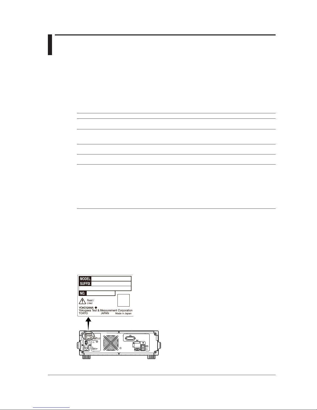
AQ6150B and AQ6151B
Check that the product that you received is what you ordered by referring to the model name and suffix
code given on the name plate on the rear panel.
MODEL SUFFIX
1
Specifications
AQ6150B Optical Wavelength Meter
AQ6151B Optical Wavelength Meter
Specifications
Code
-10
-20
-30
Standard type (1270 nm - 1650 nm)
Extended type (1200 nm - 1700 nm)
Wide range type (900 nm - 1700 nm)
Wavelength
Detection
-SW
-MW
Single-wavelength type
Multi-wavelength type
Optical
Connector
-FCC
-SCC
FC/PC (AQ9441 Universal Adapter)
2
SC/PC (AQ9441 Universal Adapter)
2
Power cord
3
-D
-F
-R
-Q
-H
-N
-T
-B
-Y
UL/CSA standard and PSE compliant power cord, rated voltage: 125 V
VDE/Korean standard power cord, rated voltage: 250 V
Australian standard power cord, rated voltage: 250 V
British standard power cord, rated voltage: 250 V
Chinese standard power cord, rated voltage: 250 V
Brazilian standard power cord, rated voltage: 250 V
Taiwanese standard power cord, rated voltage: 125 V
Indian standard power cord, rated voltage: 250 V
No power cord included
4
1
2
3
4
For products whose suffix code contains “Z,” an exclusive manual may be included. Please read it along with
the standard manual.
Already attached to the optical input of the instrument front panel.
Make sure that the attached power cord meets the designated standards of the country and area that you are
using it in.
Prepare a power cord that complies with the standard specified by the country or region that the instrument will
be used in.
No. (Instrument number)
When contacting the dealer from which you purchased the instrument, please give them the instrument
number.
___-____
___-____
Page 6
iv
IM AQ6150B-02EN
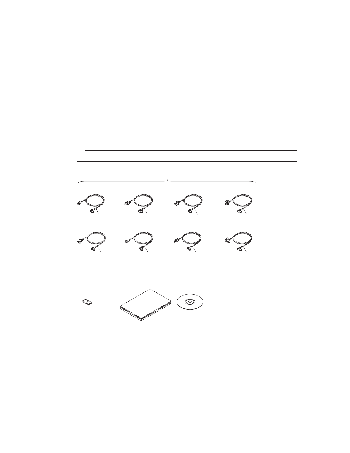
Standard Accessories
The instrument is shipped with the following accessories. Make sure that all accessories are present
and undamaged.
Item Model Quantity Specifications
Power cord
*
A1006WD
A1009WD
A1024WD
A1054WD
A1064WD
A1088WD
A1100WD
A1101WD
1 UL/CSA standard and PSE compliance
VDE/Korean standard
Australian standard
British standard
Chinese standard
Brazilian standard
Taiwanese standard
Indian standard
Rubber feet A9088ZM 2 1 A9088ZM sheet
Manuals
Printed Manuals IM AQ6150B-02EN 1 This guide.
IM AQ6150B-92Z1 1 The user’s manual for China
PM 113-01Z2 1 List of worldwide contacts
Manual CD A1027US 1 Contains PDFs of the user’s manuals (For the types of
manuals that CD contains, see Manual CD below.)
Standard accessories are not covered by warranty of this instrument.
D
F R
H
N
T
Q
B
UL/CSA Standard, PSE
A1006WD
VDE/Korean Standard
A1009WD
Australian Standard
A1024WD
Power cord (one cord that matches the suffix code is included)*
Chinese Standard
A1064WD
Brazilian Standard
A1088WD
Taiwanese Standard
A1100WD
British Standard
A1054WD
Indian Standard
A1101WD
* Make sure that the attached power cord meets the designated standards of the country
and area that you are using it in. If the suffix code is -Y, a power cord is not included.
Manuals
• Printed Manuals • Manual CD
Rubber feet
A9088ZM
Manual CD
The English folder in the manual CD contains the PDF files shown below. The CD also contains
Japanese manuals.
File Name Manual Title Manual No.
Operation Manual.pdf AQ6150B, AQ6151B Optical Wavelength Meter
User’ s Manual
IM AQ6150B-01EN
Getting Started Guide.pdf AQ6150B, AQ6151B Optical Wavelength Meter
Getting Started Guide
IM AQ6150B-02EN
Remote Control.pdf AQ6150B, AQ6151B Optical Wavelength Meter
Remote Control User’ s Manual
IM AQ6150B-17EN
To view these user’s manuals, you need Adobe Reader.
Checking the Contents of the Package
Page 7

v
IM AQ6150B-02EN
Optional Accessories (Sold separately)
The following optional accessories are available for purchase separately. For information about
ordering accessories, contact your nearest YOKOGAWA dealer.
Use the accessories specified in this manual. Moreover, use the accessories of this product only with
Yokogawa products that specify them as accessories.
Item Model Min. Q’ty Specifications
AQ9441 Connector Adapter 813917321-FCC 1 FC type
813917321-SCC 1 SC type
Optional accessories (sold separately) are not covered by warranty of this instrument.
Checking the Contents of the Package
Page 8

vi
IM AQ6150B-02EN
Conventions Used in This Manual
Notes and Cautions
The notes and cautions in this manual are categorized using the following symbols.
Improper handling or use can lead to injury to the user or damage to the
instrument. This symbol appears on the instrument to indicate that the user must
refer to the user’s manual for special instructions. The same symbol appears in
the corresponding place in the user’s manual to identify those instructions. In the
user’s manual, the symbol is used in conjunction with the word “WARNING” or
“CAUTION.”
WARNING
Calls attention to actions or conditions that could cause serious or fatal injury to
the user, and precautions that can be taken to prevent such occurrences.
CAUTION
Calls attention to actions or conditions that could cause light injury to the user or
damage to the instrument or user’s data, and precautions that can be taken to
prevent such occurrences.
French
AVERTISSEMENT
Attire l’attention sur des gestes ou des conditions susceptibles
de provoquer des blessures graves (voire mortelles), et sur les
précautions de sécurité pouvant prévenir de tels accidents.
ATTENTION
Attire l’attention sur des gestes ou des conditions susceptibles de
provoquer des blessures légères ou d’endommager l’instrument ou les
données de l’utilisateur, et sur les précautions de sécurité susceptibles
de prévenir de tels accidents.
Note
Calls attention to information that is important for the proper operation of the
instrument.
Notations Used in the Procedural Explanations
The contents of the procedural explanations are indicated using the following symbols, notations, and
terminology.
Procedure
Carry out the procedure according to the step numbers. All procedures are
written under the assumption that you are starting operation at the beginning
of the procedure, so you may not need to carry out all the steps in a procedure
when you are changing the settings.
Explanation
This section describes the setup items and the limitations regarding the
procedures.
Characters and Terminology Used in Procedural Explanations
Panel Keys and Soft Keys
Bold alphanumeric characters in procedural explanations indicate panel keys that are used in the
procedure and soft keys and menu items that appear on the screen.
Unit
k: Denotes 1000. Example: 12 kg, 100 kHz
K: Denotes 1024. Example: 459 KB (file size)
Page 9

vii
IM AQ6150B-02EN
Safety Precautions
This product is designed to be used by a person with specialized knowledge.
This instrument is an IEC safety class I instrument (provided with a terminal for protective earth
grounding).
The general safety precautions described herein must be observed during all phases of operation.
If the instrument is used in a manner not specified in this manual, the protection provided by the
instrument may be impaired.
This manual is part of the product and contains important information. Store this manual in a safe place
close to the instrument so that you can refer to it immediately. Keep this manual until you dispose of
the instrument.
YOKOGAWA assumes no liability for the customer’s failure to comply with these requirements.
The following symbols are used on this instrument.
Warning: handle with care. Refer to the user’s manual or service manual. This symbol appears
on dangerous locations on the instrument which require special instructions for proper handling
or use. The same symbol appears in the corresponding place in the manual to identify those
instructions.
Alternating current
ON (power)
OFF (power)
French
Avertissement : À manipuler délicatement. Toujours se reporter aux manuels d’utilisation et
d’entretien. Ce symbole a été apposé aux endroits dangereux de l’instrument pour lesquels
des consignes spéciales d’utilisation ou de manipulation ont été émises. Le même symbole
apparaît à l’endroit correspondant du manuel pour identifier les consignes qui s’y rapportent.
Courant alternatif
Marche (alimentation)
Arrêt (alimentation)
Page 10

viii
IM AQ6150B-02EN
Failure to comply with the precautions below could lead to injury
or death or damage to the instrument.
WARNING
Use the Instrument Only for Its Intended Purpose
This optical measuring instrument is designed to measure the optical characteristics of light
sources and evaluate their performance. Do not use this instrument for anything other than as
an optical measuring instrument.
Check the Physical Appearance
Do not use the instrument if there is a problem with its physical appearance.
Use the Correct Power Supply
Make sure that the power supply voltage matches the instrument’s rated supply voltage and
that it does not exceed the maximum voltage range of the power cord to use.
Use the Correct Power Cord and Plug
To prevent electric shock or fire, be sure to use the power cord for the instrument. The main
power plug must be plugged into an outlet with a protective earth terminal. Do not invalidate
this protection by using an extension cord without protective earth grounding. Further, do not
use this power cord with other instruments.
Connect the Protective Grounding Terminal
Make sure to connect the protective earth to prevent electric shock before turning on the
power. The power cord to use is a three-prong type power cord. Connect the power cord to a
properly grounded three-prong outlet.
Do Not Impair the Protective Grounding
Never cut off the internal or external protective earth wire or disconnect the wiring of the
protective earth terminal. Doing so may result in electric shock or damage to the instrument.
Do Not Use When the Protection Functions Are Defective
Before using this instrument, check that the protection functions, such as the protective
grounding and fuse, are working properly. If you suspect a defect, do not use the instrument.
Do Not Operate in an Explosive Atmosphere
Do not operate the instrument in the presence of flammable gasses or vapors. Doing so is
extremely dangerous.
Do Not Remove the Covers or Disassemble or Alter the Instrument
Only qualified YOKOGAWA personnel may remove the covers and disassemble or alter the
instrument. The inside of the instrument is dangerous because parts of it have high voltages.
Install or Use the Instrument in Appropriate Locations
• Do not install or use the instrument outdoors or in locations subject to rain or water.
• Install the instrument so that you can immediately remove the power cord if an abnormal or
dangerous condition occurs.
Safety Precautions
Page 11

ix
IM AQ6150B-02EN
Manual CD
Never play this manual CD, which contains the user’s manuals, in an audio CD player.
Doing so may cause loss of hearing or speaker damage due to the large sounds that may be
produced.
Optional Accessories
Use the accessories specified in this manual. Moreover, use the accessories of this product
only with Yokogawa products that specify them as accessories.
Do not use faulty accessories.
CAUTION
Operating Environment Limitations
This product is a Class A (for industrial environments) product. Operation of this product in a
residential area may cause radio interference in which case the user will be required to correct
the interference.
French
AVERTISSEMENT
Utiliser l’instrument aux seules fins pour lesquelles il est prévu
Cet instrument de mesure optique est prévu pour mesurer les caractéristiques optiques des
sources lumineuses et évaluer leur performance. Ne pas utiliser cet instrument à d’autres fins
que celles de mesure optique.
Inspecter l’apparence physique
Ne pas utiliser l’instrument si son intégrité physique semble être compromise.
Vérifier l’alimentation
Assurez-vous que la tension d’alimentation correspond à la tension d’alimentation nominale
de l’appareil et qu’elle ne dépasse pas la plage de tension maximale du cordon d’alimentation
à utiliser.
Utiliser le cordon d’alimentation et la fiche adaptés
Pour éviter tout risque de choc électrique, utiliser exclusivement le cordon d’alimentation
prévu pour cet instrument. La fiche doit être branchée sur une prise secteur raccordée à la
terre. En cas d’utilisation d’une rallonge, celleci doit être impérativement reliée à la terre. Par
ailleurs, ne pas utiliser ce cordon d’alimentation avec d’autres instruments.
Brancher la prise de terre
Avant de mettre l’instrument sous tension, penser à brancher la prise de terre pour éviter
tout choc électrique. Le cordon d’alimentation à utiliser est un cordon d’alimentation à trois
broches. Brancher le cordon d’alimentation sur une prise de courant à trois plots et mise à la
terre.
Safety Precautions
Page 12

x
IM AQ6150B-02EN
Ne pas entraver la mise à la terre de protection
Ne jamais neutraliser le fil de terre interne ou externe, ni débrancher la borne de mise à la
terre. Cela pourrait entraîner un choc électrique ou endommager l’instrument.
Ne pas utiliser lorsque les fonctions de protection sont défectueuses
Avant d’utiliser l’instrument, vérifier que les fonctions de protection, telles que le raccordement
à la terre et le fusible, fonctionnent correctement. En cas de dysfonctionnement possible, ne
pas utiliser l’instrument.
Ne pas utiliser dans un environnement explosif
Ne pas utiliser l’instrument en présence de gaz ou de vapeurs inflammables. Cela pourrait
être extrêmement dangereux.
Ne pas retirer le capot, ni démonter ou modifier l’instrument
Seul le personnel YOKOGAWA qualifié est habilité à retirer le capot et à démonter ou modifier
l’instrument. Certains composants à l’intérieur de l’instrument sont à haute tension et par
conséquent, représentent un danger.
Installer et utiliser l’instrument aux emplacements appropriés
• Ne pas installer, ni utiliser l’instrument à l’extérieur ou dans des lieux exposés à la pluie ou
à l’eau.
• Installer l’instrument de manière à pourvoir immédiatement le débrancher du secteur en
cas de fonctionnement anormal ou dangereux.
Manuel CD
Ce CD contient les manuels d’utilisation. Ne jamais insérer ce CD dans un lecteur de CD
audio. Cela pourrait entraîner une perte d’audition ou l’endommagement des enceintes en
raison du volume potentiellement élevé des sons produits.
Accessoires en option
Utiliser les accessoires spécifiés dans ce manuel. En outre, utiliser les accessoires de ce
produit uniquement avec des produits Yokogawa pour lesquels ils sont spécifiés comme
accessoires.
Ne pas utiliser d’accessoires défectueux.
ATTENTION
Limitations relatives à l’environnement opérationnel
Ce produit est un produit de classe A (pour environnements industriels). L’utilisation de ce
produit dans un zone résidentielle peut entraîner une interférence radio que l’utilisateur sera
tenu de rectifier.
Safety Precautions
Page 13
xi
IM AQ6150B-02EN
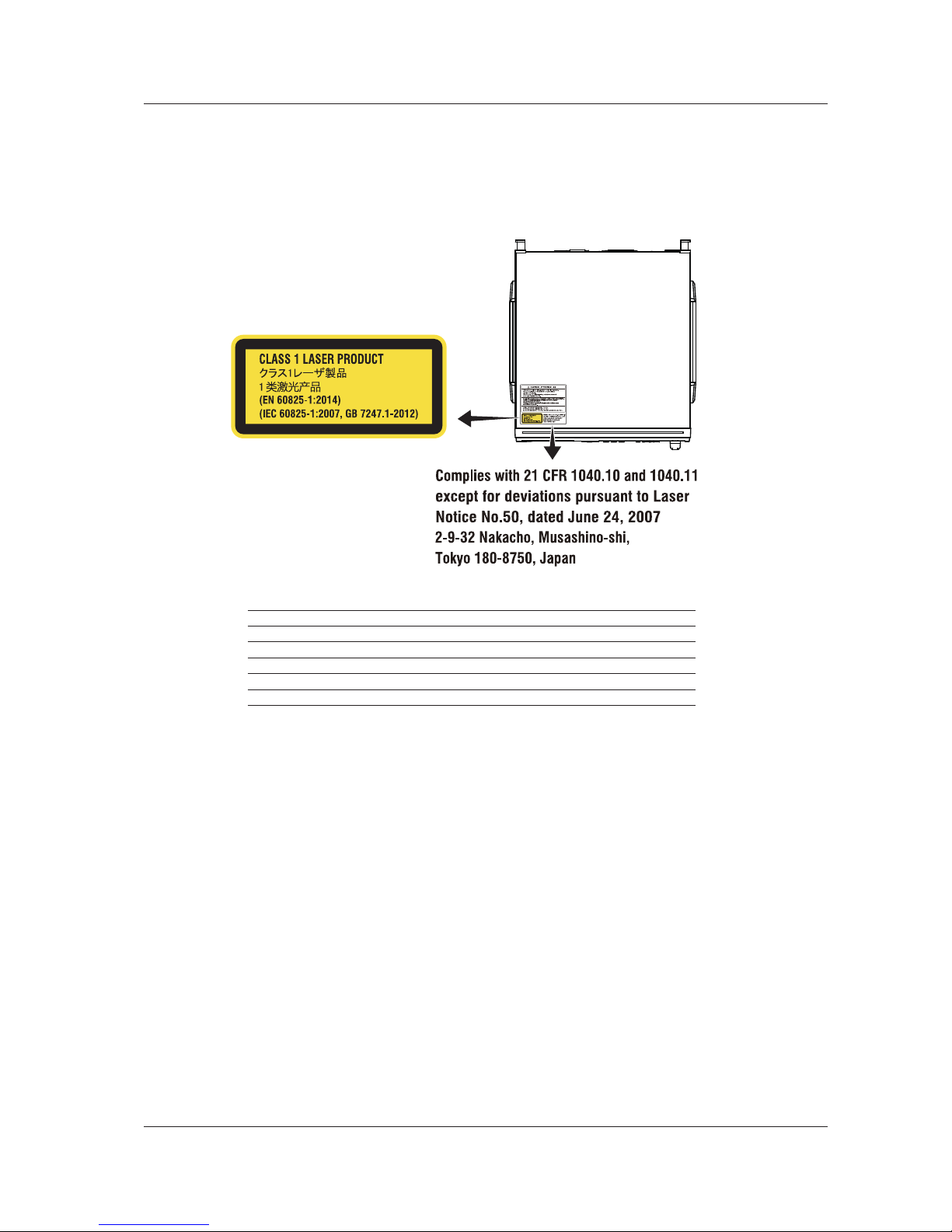
Safety Precautions for Laser Products
This instrument uses a laser light source. This instrument is a Class 1 laser product as defined by
EN 60825-1:2014/IEC 60825-1:2007 Safety of Laser Products—Part1: Equipment Classification,
Requirements and User’s Guide. In addition, this instrument complies with 21 CFR 1040.10 and
1040.11 except for deviations pursuant to Laser Notice No. 50, dated June 24, 2007.
Laser Class 1 Label
Built-in Laser Information
Item AQ6150B AQ6151B
Laser class 3R 3B
Max. output power 5 mW Max. 15 mW Max.
Wavelength 633 nm 633 nm
Pulse duration CW CW
Numerical aperture Collimated Collimated
The instrument does not have an optical output for lasers.
Safety Precautions
Page 14
xii
IM AQ6150B-02EN
Regulations and Sales in Each Country or Region
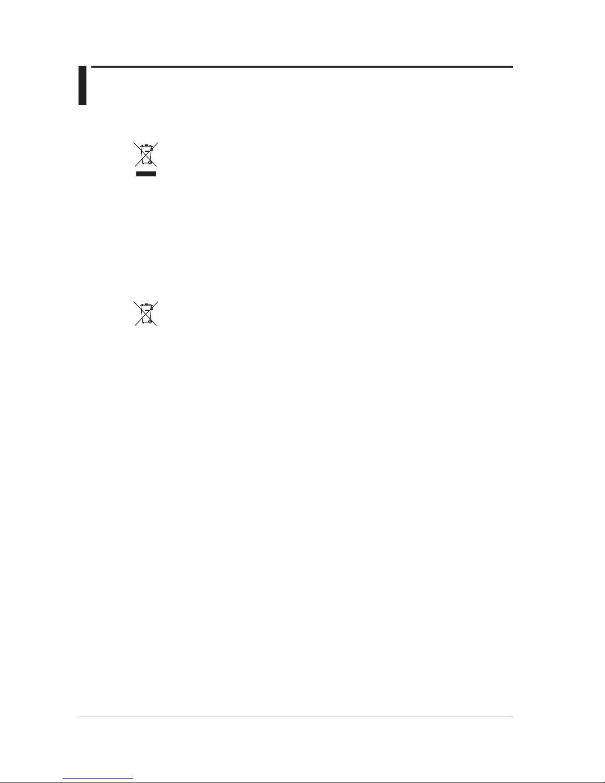
Waste Electrical and Electronic Equipment
Waste Electrical and Electronic Equipment (WEEE), Directive
(This directive is valid only in the EU.)
This product complies with the WEEE directive marking requirement. This marking indicates
that you must not discard this electrical/electronic product in domestic household waste.
Product Category
With reference to the equipment types in the WEEE directive, this product is classified as a
“Monitoring and control instruments” product.
When disposing of products in the EU, contact your local Yokogawa Europe B.V. office. Do not
dispose in domestic household waste.
EU Battery Directive
EU Battery Directive
(This directive is valid only in the EU.)
Batteries are included in this product. This marking indicates they shall be sorted out and
collected as ordained in the EU battery directive.
Battery type: Lithium battery
You cannot replace batteries by yourself. When you need to replace batteries, contact your
local Yokogawa Europe B.V. office.
Authorized Representative in the EEA
Yokogawa Europe B.V. is the authorized representative of Yokogawa Test & Measurement Corporation
for this product in the EEA. To contact Yokogawa Europe B.V., see the separate list of worldwide
contacts, PIM 113-01Z2.
關於在台灣銷售
This section is valid only in Taiwan.
關於在台灣所販賣的符合其相關規定的電源線
A1100WD
的限用物質含量信息,請至下麵的網址進行查詢
https://tmi.yokogawa.com/support/service-warranty-quality/product-compliance/
Page 15

xiii
IM AQ6150B-02EN
1
2
3
4
5
App
Index
Contents
List of Manuals ...................................................................................................................................i
Checking the Contents of the Package............................................................................................ iii
Conventions Used in This Manual ...................................................................................................vi
Safety Precautions .......................................................................................................................... vii
Regulations and Sales in Each Country or Region ......................................................................... xii
Chapter 1 Component Names and Functions
1.1 Front Panel ....................................................................................................................... 1-1
1.2 Rear Panel ....................................................................................................................... 1-2
1.3 Keys ................................................................................................................................. 1-3
1.4 Screens (-MW (multi-wavelength) suffix code type) ......................................................... 1-5
1.5 Screens (-SW (single-wavelength) suffix code type) ........................................................ 1-8
Chapter 2 Making Preparations for Measurements
2.1 Handling Precautions ....................................................................................................... 2-1
2.2 Installing the Instrument ................................................................................................... 2-3
2.3 Connecting to the Power Supply and Turning the Power Switch On and Off ................... 2-6
2.4 Attaching a Connector Adapter .......................................................................................2-11
2.5 Connecting a Mouse, Keyboard, USB Storage Device .................................................. 2-13
2.6 Connecting an Optical Fiber ........................................................................................... 2-15
2.7 Setting the Clock ............................................................................................................ 2-18
2.8 Recommended Part Replacement ................................................................................. 2-19
Chapter 3 Key Operations and Entering Values and Character Strings
3.1 Soft Key Description ......................................................................................................... 3-1
3.2 Mouse and Keyboard Operation ...................................................................................... 3-3
3.3 Entering Values and Character Strings ............................................................................ 3-4
Chapter 4 Maintenance, Inspection, and Storage
4.1 Messages ......................................................................................................................... 4-1
4.2 Updating the Firmware ..................................................................................................... 4-3
4.3 Routine Maintenance ....................................................................................................... 4-6
4.4 Storage Precautions ......................................................................................................... 4-8
4.5 Replacing Fuses ............................................................................................................... 4-9
4.6 Disposal .......................................................................................................................... 4-10
Chapter 5 Specifications
5.1 Optical and General Specifications .................................................................................. 5-1
5.2 External Dimensions ........................................................................................................ 5-4
Appendix
Appendix 1 MICROSOFT SOFTWARE LICENSE TERMS .................................................. App-1
Index
Page 16
1-1
IM AQ6150B-02EN
Component Names and Functions
1
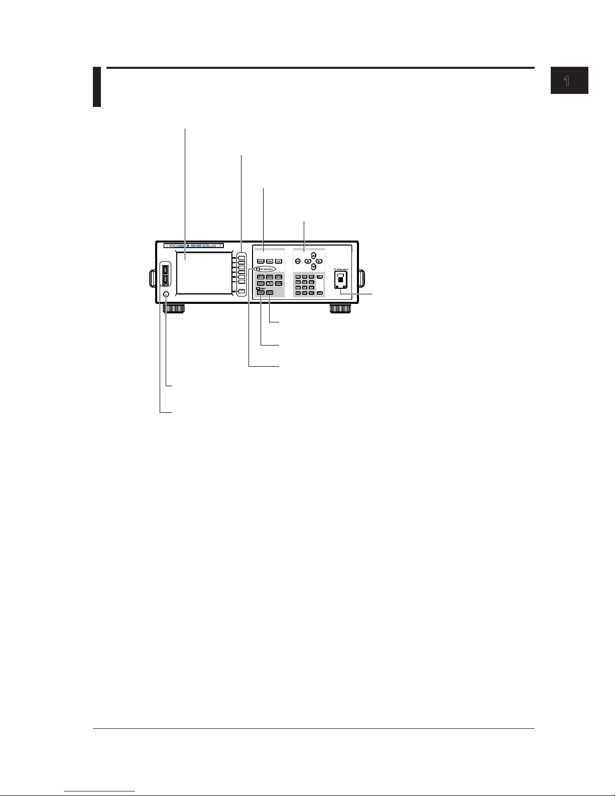
1.1 Front Panel
POWER
Display
Displays measured waveforms, measurement conditions, measured values, etc.
Soft key section
Control the functions that are assigned to soft keys,
which appear on the right of the LCD display.
FUNCTION section
Set all features including measurement, setup, and display.
DATA ENTRY section
Enter measurement condition parameters and labels.
POWER switch
A switch for starting and stopping the instrument.
USB port
Connect a USB storage device, USB mouse, or USB keyboard.
LOCAL key
Clears remote mode
PRT SCN key
Saves a screen capture
REF LASER STATUS LED
Indicates the internal reference light source status
OPTICAL INPUT
Connect the optical input signal here.
Chapter 1 Component Names and Functions
Page 17
1-2
IM AQ6150B-02EN
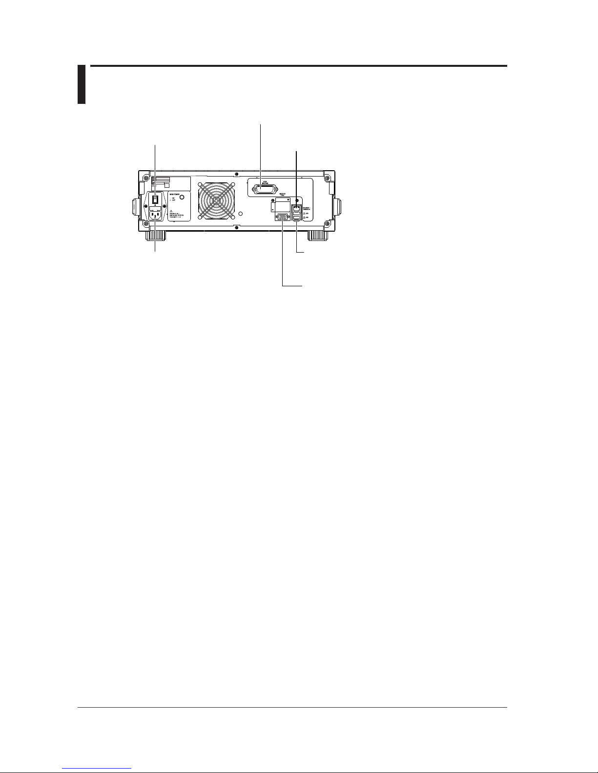
1.2 Rear Panel
ETHERNET port
Use this port to connect the instrument to a network.
GP-IB connector
Use this connector to control the instrument from a PC.
VIDEO OUT
Video signal (VGA) terminal
Use this terminal to view the instrument screen
on an external display.
MAIN Power switch
Used to turn the main power
ON/OFF.
Power inlet
Connect the power cord.
USB port
Connect a USB storage device, USB mouse,
or USB keyboard.
Page 18
1-3
IM AQ6150B-02EN
Component Names and Functions
1
1.3 Keys
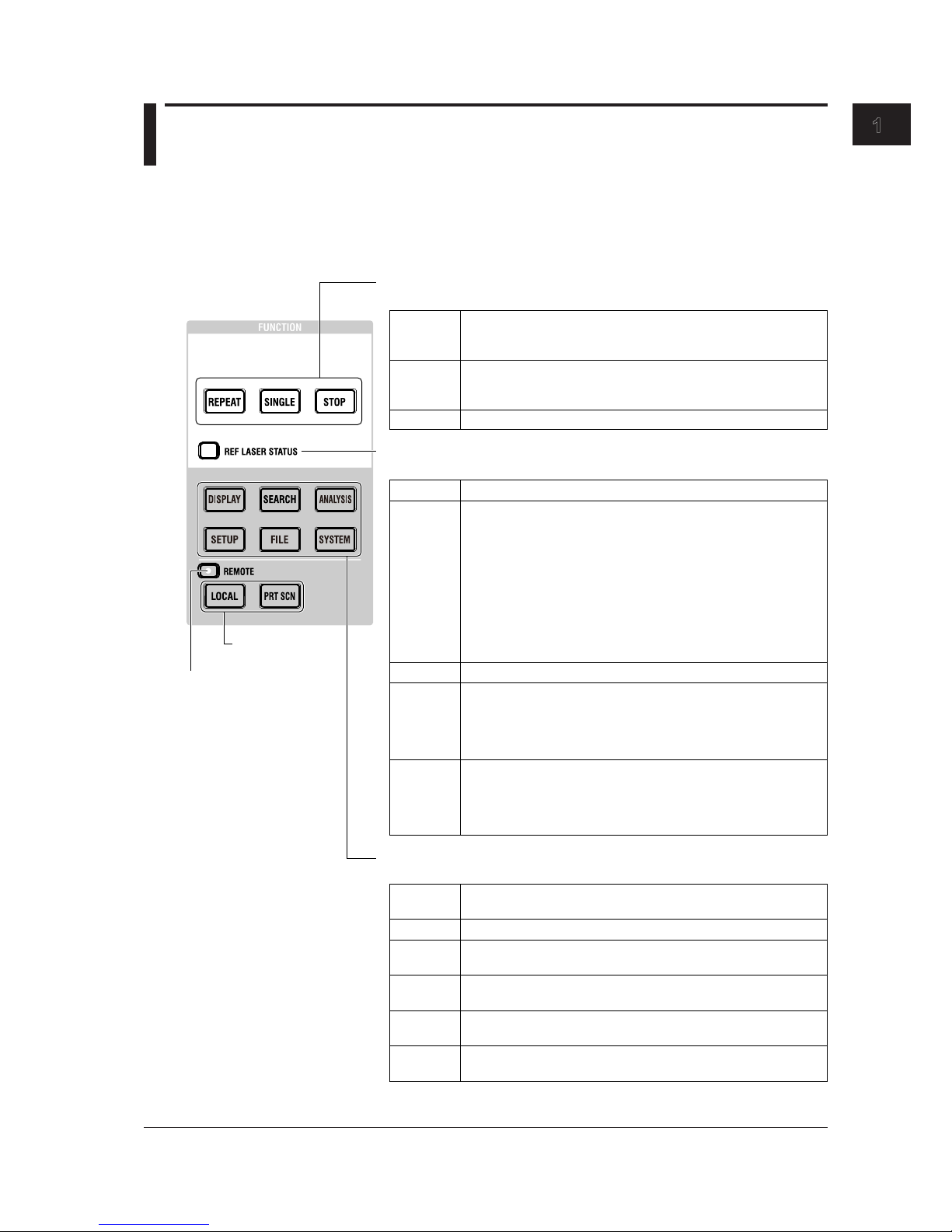
FUNCTION Section
The FUNCTION section consists of three measurement control keys, six function keys, and two
auxiliary keys. Pressing a function key shows the setup menur for the corresponding function on the
right side of the screen.
Measurement control keys
Starts or stops measurement.
Internal reference light source status display
Indicates the operating status of the internal He-Ne laser.
Function keys
Set measurement conditions, data saving and loading, etc.
Auxiliary key
See section 1.1.
REPEAT
SINGLE
STOP
Stops the measurement.
Normal status (stable laser output). Measurement is possible.
Off
The laser is not being output. Measurement is not possible.
Blinking
orange
Red
Orange
Green
SYSTEM
DISPLAY
SEARCH Displays a setup menu for searching measured peaks.
ANALYSIS
SETUP
FILE
Laser output is in preparation. This indicates the status until the laser
output stabilizes.
Measurement is not possible while the message “REF LASER
STARTING” is displayed. If this status lasts approximately 5 minutes,
the instrument assumes that a malfunction has occurred and turns
the LED red.
When the instrument is ready to measure, the message disappears.
It takes approximately 1 minute for the laser output to stabilize.
To make accurate measurements, wait for the laser output to
stabilize.
Starts repeat measurements. The key illuminates while the
measurement is in progress. Measurement is repeated until you
press STOP.
Starts a single measurement. The key illuminates while the
measurement is in progress. Measurement automatically stops after
one measurement.
When the light source approaches its service life, the message “It is
about time to plan for REF LASER replacement" appears.
The operating time of the laser output has reached the replacement
reference time (30000 hours).
Measurement is possible, but replace the light source early.
If a malfunction occurs, the message “REF LASER or interferometer
is out of order. Please contact our sales representatives” appears.
Measurement is not possible.
For information on replacing the light source, contact your nearest
YOKOGAWA dealer.
Displays a setup menu for selecting measurement screens and
setting waveform display scales.
Displays a menu for performing drift measurements, FP-LD analysis,
and data logging.
Displays a setup menu for setting measurement conditions (type of
light, detection threshold, unit, etc.)
Displays a setup menu for saving and loading measured data and
settings from a USB storage device or internal storage.
Displays a setup menu for setting network parameters, showing
system information, setting the clock, and so on.
Remote control indicator
Illuminates in remote control
mode.
See section 1.2 in the
Remote Control User’s
Manual, IM AQ6150B-17EN.
Page 19
1-4
IM AQ6150B-02EN
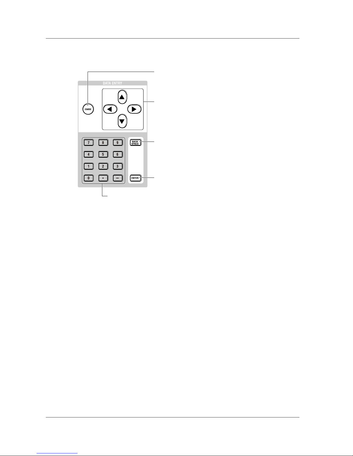
DATA ENTRY Section
You can enter various measurement parameters from the DATA ENTRY section.
You can use arrow keys and the numeric keypad to enter parameters.
Arrow keys
Increase or decrease values, move the cursor (up and down) in file lists,
move the cursor (up, down, left, and right) in the character selection
area of character input screens, enter numeric keypad values (left and
right), and so on.
To increase a value: ▲ or ► key
To decrease a value: ▼ or ◄ key
COARSE key
Turn this key on to select the next higher digit or increases the step by
which the value changes.
Each time you press the key, the setting toggles between on and off.
When set to on, the key illuminates.
BACK SPACE key
Press this key to erase the key before the cursor.
The last entered number (at the right end) is erased, and you can enter
the correct number.
If you press BACK SPACE repeatedly and the numeric keypad input
area becomes empty, the numeric keypad input area disappears.
ENTER key
Confirms the value that you have entered with the numeric keypad, in
the parameter input window, or character input screen.
Numeric keypad
You can use the numeric keypad to enter values directly in parameter input windows.
If you press a soft key that has a parameter, the current value appears in a parameter
value display area. If you press a key on the numeric keypad in this condition, the
number that you selected appears in the area.
If the value that you enter with the numeric keypad is outside the allowed range, it is
reset to the closest value within the range.
1.3 Keys
Page 20
1-5
IM AQ6150B-02EN
Component Names and Functions
1
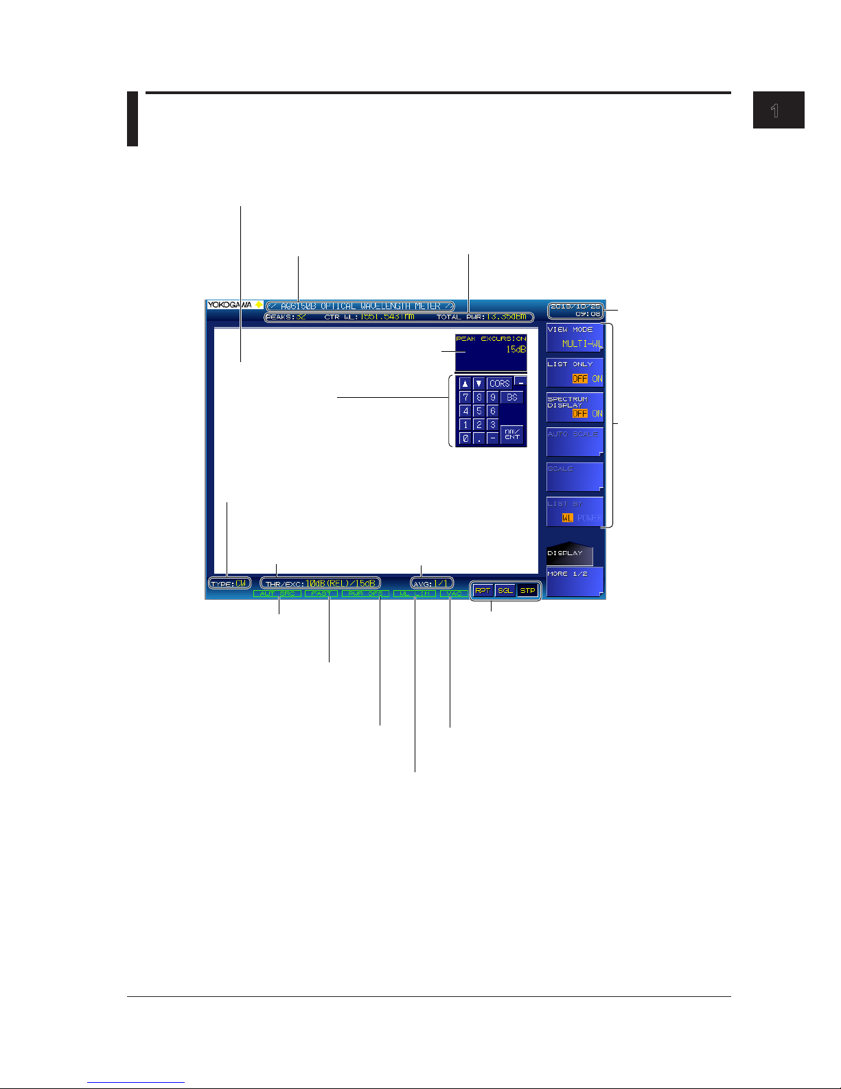
1.4 Screens
(-MW (multi-wavelength) suffix code type)
Main Screen
Label
You can display text of
your choice using up to
52 characters.
Measurement summary
Displays the number of detected peaks (PEAKS),
center wavelength (CTR WL), and total power
(TOTAL PWR)
Measurement result display
Displays the peak window, peak list window, and spectrum window.
The display varies depending on the VIEW mode. Details are given later.
Date and time
Setup menu
Measurement parameter value input
Numeric keypad screen
Peak detection threshold
and excursion values
Averaging count
Illuminates when the power offset is
not zero
See section 2.6.
Illuminates when the
auto peak search
feature is on
Measurement control keys
Indicates the state of the measurement control keys.
If you connect a mouse to the instrument, you can
click these keys to perform the same operations that
you can using the front panel’s measurement
control keys.
RPT: Repeat measurement
SGL: Single measurement
STP: Stop measurement
If you connect a mouse to the instrument,
you can perform the same operations that
you can using the front panel’s numeric keypad.
Selected medium
VAC: Vacuum
AIR: Standard air
Selected light type
CW: CW (NARROW)
MOD: MODULATED (BROAD)
Illuminates when measurement
wavelength range limit is on
See section 3.6 in the User’s Manual,
IM AQ6150B-01EN.
Illuminates when the
update rate feature is FAST
See section 2.7 in the User’s
Manual, IM AQ6150B-01EN
Page 21
1-6
IM AQ6150B-02EN
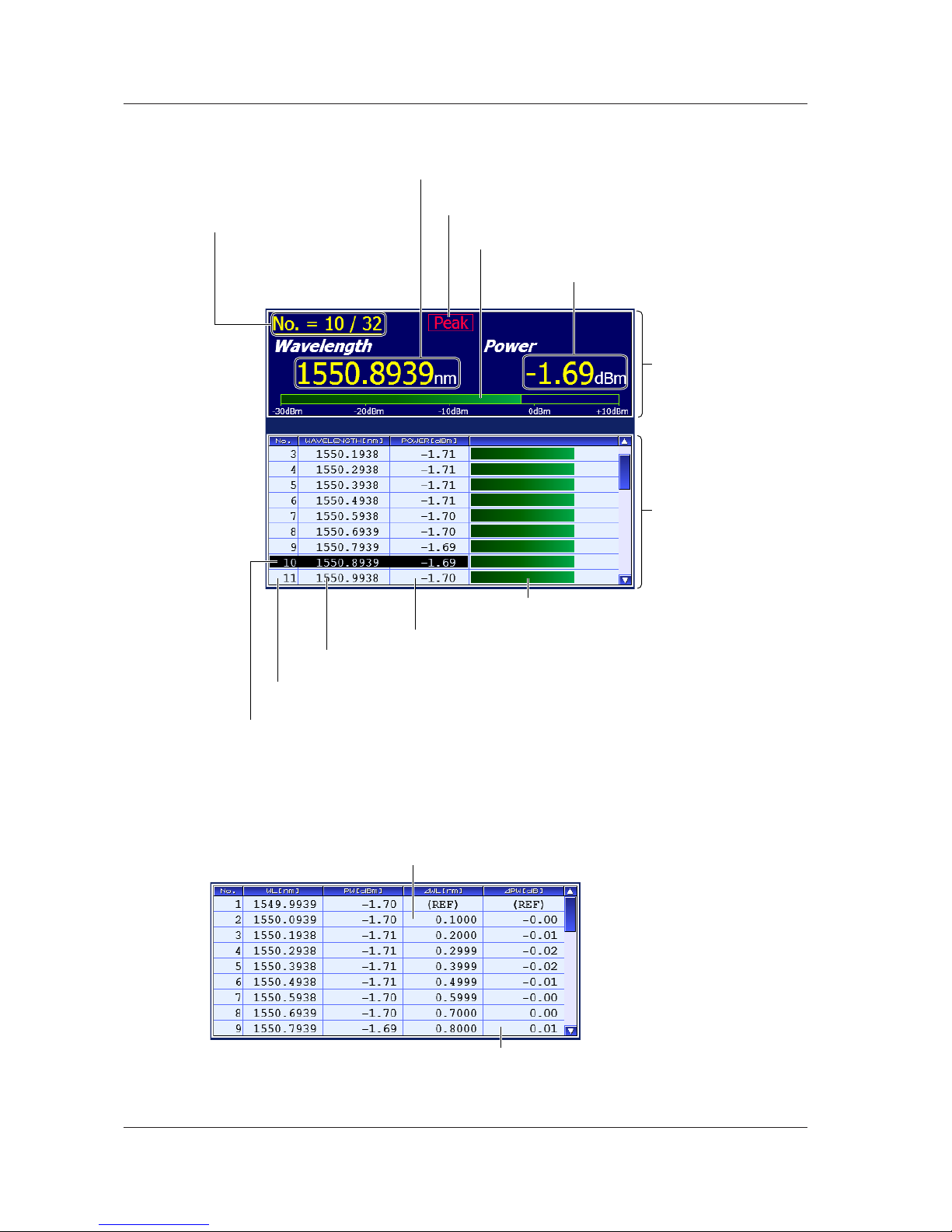
Multi Peak Screen for Absolute Values
For the operating procedure, see section 4.2 in the User’s Manual, IM AQ6150B-01EN.
Peak window
Peak list window
A list of detected peaks
Power
The power the current peak
Power bar
The ratio of the power value
Peak value
Indicates that the current peak is the maximum (power)
Wavelength
The wavelength of the current peak
Current peak number/the number of
detected peaks
Indicates which peak among the
detected peaks is shown in the peak
window.
Example: 10th peak among the 32
peaks detected
Power bar
Ratio of the power of each peak relative to
the maximum measurable power
Power
The power of each peak
Wavelength
The wavelength of each peak
Number
Numbers automatically assigned to all detected peaks
Cursor display
Move the cursor to select the peak (current peak) to
show in the peak window.
Multi Peak Screen for Relative Values
The peak window is the same as in the multi peak screen for absolute values, which is shown above.
For the operating procedure, see section 4.3 in the User’s Manual, IM AQ6150B-01EN.
ΔPW
Power relative to the reference (REF) peak
ΔWL
Wavelength relative to the reference (REF) peak
1.4 Screens (-MW (multi-wavelength) suffix code type)
Page 22
1-7
IM AQ6150B-02EN
Component Names and Functions
1
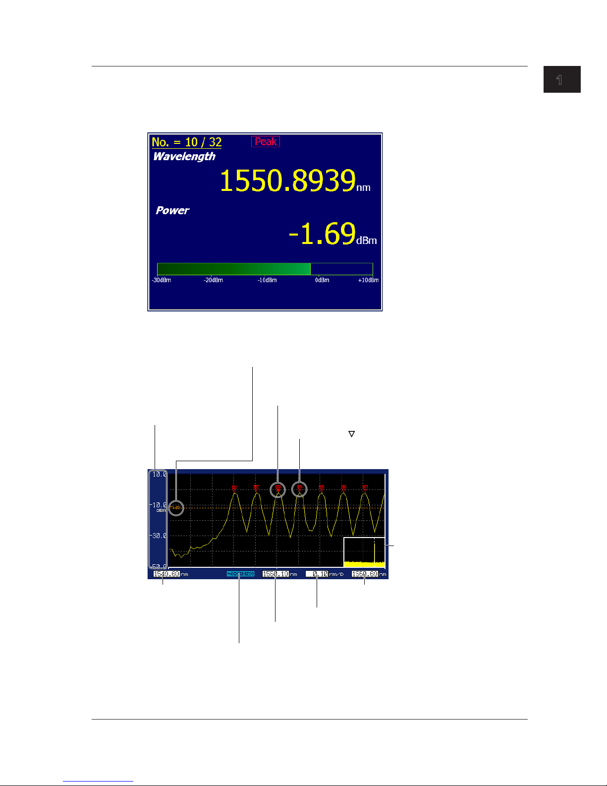
Single Peak Screen
Only the peak window is displayed. The displayed contents and features are the same as those
of the multi peak screens.
For the operating procedure, see section 4.1 in the User’s Manual, IM AQ6150B-01EN.
Spectrum Window
For the operating procedure, see section 4.5 in the User’s Manual, IM AQ6150E-01EN.
Scale
Displays a power scale of
absolute values
Threshold
The peak detection threshold.
If the threshold is specified with a relative value, it is
converted to an absolute value and displayed.
Fixed marker ( )
A numbered marker that is automatically
assigned during peak detection
The maximum number is 1024.
Moving marker (▼)
This marker appears on the current peak.
The marker is filled with a color.
Overview window
The entire spectrum waveform
Start wavelength of
the scale
The start wavelength
of the display range
Zoom
Appears when the spectrum is being zoomed in on
Center wavelength of the scale
The center wavelength of the display range
Wavelength per division
Stop wavelength of the scale
The stop wavelength of the display range
1.4 Screens (-MW (multi-wavelength) suffix code type)
Page 23
1-8
IM AQ6150B-02EN
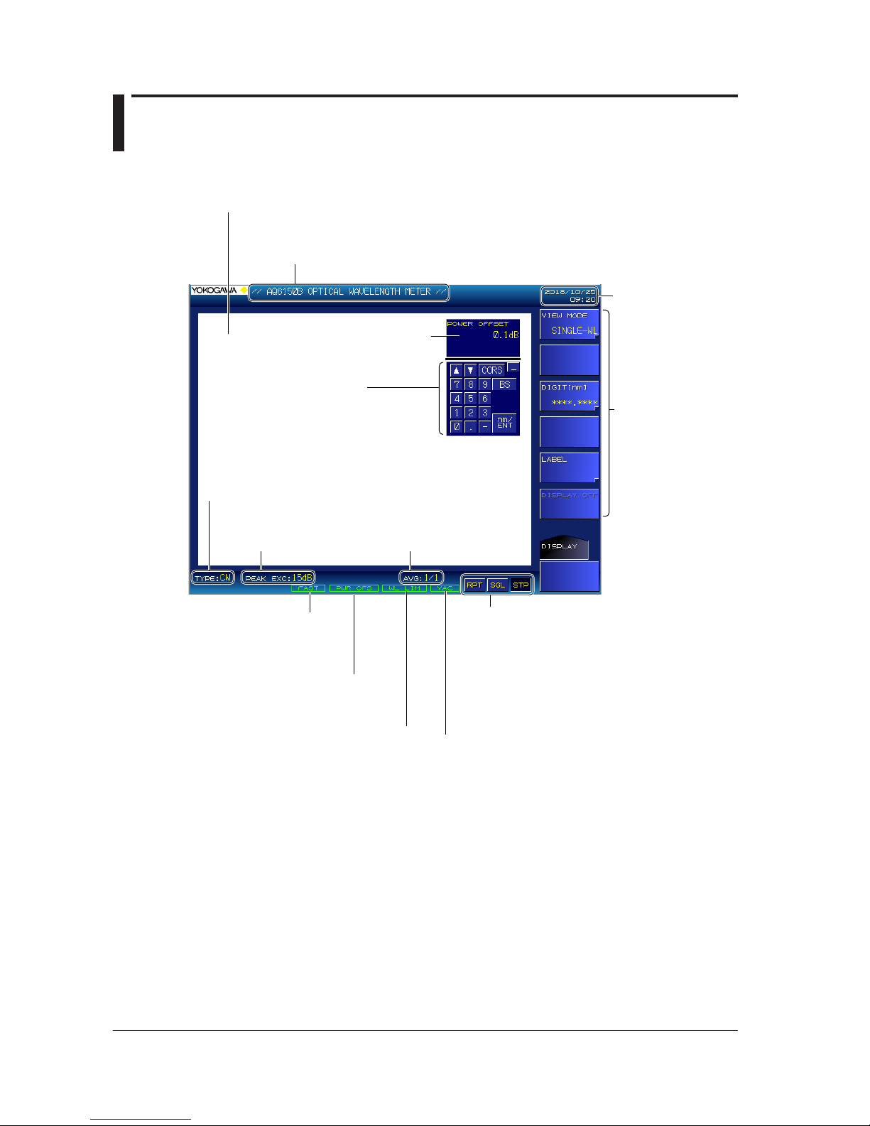
1.5 Screens
(-SW (single-wavelength) suffix code type)
Main Screen
Illuminates when the update
rate feature is FAST
See section 2.7 in the User’s
Manual, IM AQ6150B-01EN
Measurement result display
The peak wavelength and power value are displayed.
During drift measurement, this display shows drift measurement results.
Date and time
Setup menu
Measurement parameter
value input
Numeric keypad screen
If you connect a mouse to the
instrument, you can perform the same
operations that you can using the front
panel’s numeric keypad.
Peak excursion Averaging count
Illuminates when measurement
wavelength range limit is on
See section 3.6 in the User’s Manual,
IM AQ6150B-01EN.
Illuminates when the power offset
is not zero
See section 2.6.
Label
You can display text of your choice using up to 52 characters.
Selected light type
CW: CW (NARROW)
MOD: MODULATED (BROAD)
Selected medium
VAC: Vacuum
AIR: Standard air
Measurement control keys
Indicates the state of the measurement control keys.
If you connect a mouse to the instrument, you can
click these keys to perform the same operations that
you can using the front panel’
s measurement control
keys.
RPT: Repeat measurement
SGL: Single measurement
STP: Stop measurement
Page 24

1-9
IM AQ6150B-02EN
Component Names and Functions
1
Display Screen for Normal Measurement
This screen shows the detected peak wavelength and power value.
Wavelength
The peak wavelength
Power bar
The ratio of the power value
Power
The peak power value
Display Screen for Drift Measurement
This screen shows the current peak measurement result and the drift measurement result.
Current measurement result
(same as normal measurement)
Drift measurement result
For details on parameters,
see section 3.5 in the User’s
Manual, IM AQ6150B-01EN.
1.5 Screens (-SW (single-wavelength) suffix code type)
Page 25

2-1
IM AQ6150B-02EN
Making Preparations for Measurements
1
2
2.1 Handling Precautions
Safety Precautions
If you are using this instrument for the first time, make sure to read “Safety Precautions” on pages vii to x.
Do Not Remove the Case
Do not remove the case from the instrument. Some sections inside the instrument have high
voltages that are extremely dangerous. For internal inspection and adjustment, contact your nearest
YOKOGAWA dealer.
Unplug If Abnormal Behavior Occurs
If you notice smoke or unusual odors coming from the instrument, immediately turn off the power and
unplug the power cord. Then, contact your nearest YOKOGAWA dealer.
Do Not Damage the Power Cord
Nothing should be placed on top of the power cord. The power cord should also be kept away from
any heat sources. When unplugging the power cord from the outlet, never pull by the cord itself. Be
sure to hold and pull by the plug. If the power cord is damaged or if you are using the instrument in a
location where the power supply specifications are different, purchase a power cord that matches the
specifications of the region that the instrument will be used in.
Operating Environment and Conditions
This instrument complies with the EMC standard under specific operating environment and operating
conditions. If the installation, wiring, and so on are not appropriate, the compliance conditions of the
EMC standard may not be met. In such cases, the user will be required to take appropriate measures.
General Handling Precautions
Do Not Place Objects on Top of the Instrument
Never place objects such as other instruments or objects that contain water on top of the instrument.
Doing so may damage the instrument.
Do Not Damage the LCD
Because the LCD is very vulnerable and can be easily scratched, do not allow any sharp objects near it.
Chapter 2 Making Preparations for Measurements
Page 26

2-2
IM AQ6150B-02EN
When Carrying the Instrument
Be sure to turn off the power switch and remove the power cord and other connected cables before
carrying the instrument. As indicated in the following figure, use both hands to firmly hold the handles
when carrying the instrument.
Handle
Handle
WARNING
• When you hold or put away the handle, be careful not to get your hand caught between the
handle and the case.
• When you carry the instrument, be careful not to get your hand caught between the wall,
installation surface, or other objects and the instrument.
French
AVERTISSEMENT
• Lorsque vous attrapez ou rabattez la poignée, veillez à ne pas vous coincer la main entre
la poignée et l’instrument.
• Lorsque vous déplacez l’instrument, veillez à ne pas vous coincer la main entre l’instrument
et le mur, la surface d’installation ou tout autre objet.
When Cleaning the Instrument
When cleaning the case or the operation panel, first remove the power cord from the outlet, and then
wipe with a dry, soft, clean cloth. Do not use chemicals such as benzene or thinner. Doing so may
cause discoloring and deformation.
2.1 Handling Precautions
Page 27

2-3
IM AQ6150B-02EN
Making Preparations for Measurements
1
2
2.2 Installing the Instrument
WARNING
• This instrument is designed to be used indoors. Do not install or use it outdoors.
• Install the instrument so that you can immediately remove the power cord if an abnormal or
dangerous condition occurs.
CAUTION
• If you block the inlet holes on the bottom or the exhaust holes on the rear side of the
instrument, the instrument will become hot and may break down. Also, high temperatures
may shorten the service life of the internal reference light source (He-Ne laser).
• Do not place this instrument on top of another device that is emitting heat. If heat enters
through the inlet holes on the bottom of the instrument, the instrument will become hot and
may break down.
French
AVERTISSEMENT
• L’instrument est prévu pour une utilisation en intérieur. Ne pas l’installer, ni l’utiliser à
l’extérieur.
• Installer l’instrument de manière à pourvoir immédiatement le débrancher du secteur en
cas de fonctionnement anormal ou dangereux.
ATTENTION
• Si vous bloquez les orifices d’entrée situés sous l’instrument ou les orifices de sortie
arrière, l’instrument surchauffe et risque de tomber en panne. En outre, les températures
élevées risquent d’écourter la durée de vie de la source lumineuse de référence interne
(laser He-Ne).
• Ne pas placer cet instrument au dessus d’un autre dispositif qui émet de la chaleur. Si
la chaleur pénètre à travers les orifices d’entrée situés au sous l’instrument, celui-ci se
chauffera et pourrait tomber en panne.
Page 28

2-4
IM AQ6150B-02EN
Installation Conditions
Install the instrument in a place that meets the following conditions.
Well-Ventilated Location
There are inlet holes on the bottom side of the instrument. There are also exhaust holes on the rear
side. To prevent internal overheating, allow for enough space around the instrument (see the figure
below), and do not block the inlet and exhaust holes.
20 cm or more
When connecting cables, allow for enough space, above and beyond the space shown in the figure
above, to carry out the procedure.
Ambient Temperature and Humidity
Ambient temperature 5 to 35 °C
Ambient humidity 20 to 85% RH (no condensation)
Note
Condensation may form when moving the instrument from a low temperature or humidity environment to a
high temperature or humidity environment, or when there is a sudden change in temperature. In such cases,
before you use the instrument, allow it to adjust to the ambient temperature.
If you transport the instrument in its packing box, to prevent condensation, allow it to adjust to the new
ambient temperature before taking it out of the box.
Flat, Even Surface
Install the instrument on a stable surface that is level in all directions and that is not slippery. If you
use the instrument in an unstable location or on a slippery surface, the instrument may fall off its
platform or hit other devices due to the vibration that the instrument produces during operation.
If the instrument is installed in a horizontal position, the supplied rubber stoppers can be attached to
the feet at the rear of the instrument to prevent the instrument from sliding.
Rubber foot
A9088ZM
Foot at the rear of the
bottom of the instrument
2.2 Installing the Instrument
Page 29

2-5
IM AQ6150B-02EN
Making Preparations for Measurements
1
2
Rack Mounting
To rack-mount the instrument, use the separately sold rack mount kit.
Item Model
Model 751535-E3 Rack mount kit (for mounting one instrument on an EIA standard
rack)
751535-E3
Model 751535-J3 Rack mount kit (for mounting one instrument on a JIS standard
rack)
751535-J3
An outline of the mounting procedure is given below. For detailed instructions, see the manual that
is included with the rack mount kit.
1.
Remove the handles from both sides of the instrument.
2.
Remove the four feet from the bottom of the instrument.
3.
Remove the four seals covering the rack mount attachment holes. The holes are on the sides
of the instrument near the front.
4.
Place seals over the feet and handle attachment holes.
5.
Attach the rack mount kit to the instrument.
6.
Mount the instrument on a rack.
How to remove a handle cover
Note
• When rack-mounting the instrument, allow at least 5 cm of space around the bottom panel inlet holes to
prevent internal heating. Allow at least 20 cm around the rear panel exhaust holes.
• Make sure to provide adequate support from the bottom of the instrument. The support should not block
the inlet and vent holes.
• Store the removed parts in a safe place.
• When rack-mounting the instrument, remove the feet from the rear of the instrument if they are coming
into contact with the rack and are thus preventing you from rack-mounting the instrument. After you have
rack-mounted the instrument, re-attach the feet to the rear of the instrument.
In this case, be sure to attach the brackets to the instrument before you remove the feet from the rear
of the instrument. If you don’t, the instrument’s cover may come loose and fall when you rack-mount the
instrument.
Do Not Install the Instrument in the Following Kinds of Places
• Outdoors.
• In a location where flammable or explosive gasses, steam, or dust is present or a location in which
explosion or fire may occur (dangerous location)
• In direct sunlight or near heat sources
• Where the instrument is exposed to water or other liquids.
• In an environment with excessive amounts of soot, steam, dust, or corrosive gas
• In an environment that is subject to large levels of mechanical vibration
• On an unstable surface
2.2 Installing the Instrument
Page 30

2-6
IM AQ6150B-02EN
2.3 Connecting to the Power Supply and Turning
the Power Switch On and Off
Before Connecting the Power Supply
Make sure to follow the warnings below when connecting the power supply. Failure to do so may
cause electric shock or damage to the instrument.
WARNING
• Make sure that the power supply voltage matches the instrument’s rated supply voltage
and that it does not exceed the maximum voltage range of the power cord to use.
• Connect the power cord after checking that the main power switch of the instrument is
turned off.
• To prevent electric shock or fire, use the power cord for the instrument.
• Make sure to connect protective earth grounding to prevent electric shock. Connect the
power cord to a three-prong power outlet with a protective earth terminal.
• Do not use an ungrounded extension cord. If you do, the instrument will not be grounded.
• If there is no AC outlet that is compatible with the power cord that you will be using and you
cannot ground the instrument, do not use the instrument.
French
AVERTISSEMENT
• Assurez-vous que la tension d’alimentation correspond à la tension d’alimentation
nominale de l’appareil et qu’elle ne dépasse pas la plage de tension maximale du cordon
d’alimentation à utiliser.
• Brancher le cordon d’alimentation après avoir vérifié que l’interrupteur d’alimentation
principal de l’instrument est sur OFF.
• Pour éviter tout risque de choc électrique, utiliser exclusivement le cordon d’alimentation
prévu pour cet instrument.
• Relier l’instrument à la terre pour éviter tout risque de choc électrique. Brancher le cordon
d’alimentation sur une prise de courant à trois plots reliée à la terre.
• Toujours utiliser une rallonge avec broche de mise à la terre, à défaut de quoi l’instrument
ne serait pas relié à la terre.
• Si une sortie CA conforme au câble d’alimentation fourni n’est pas disponible et que vous
ne pouvez pas relier l’instrument à la terre, ne l’utilisez pas.
Page 31

2-7
IM AQ6150B-02EN
Making Preparations for Measurements
1
2
Connecting the Power Cord
1.
Check that the MAIN POWER switch on the rear panel is off.
2.
Connect the power cord plug to the power inlet on the rear panel.
3.
Connect the other end of the cord to an outlet that meets the following conditions. Use a
grounded three-prong outlet.
Item
Rated supply voltage* 100 VAC to 240 VAC
Permitted supply voltage range 90 VAC to 264 VAC
Rated power supply frequency 50/60 Hz
Permitted supply frequency range 48 Hz to 63 Hz
Maximum power consumption Approx. 100 VA
* This instrument can use a 100 V or a 200 V power supply. The maximum rated voltage
differs according to the type of power cord. Check that the voltage supplied to the
instrument is less than or equal to the maximum rated voltage of the power cord that you
will be using before use.
Three-prong outlet
Power cord
OFF
MAIN POWER
ON
100
240V
AC
150VA
MAX
50/60Hz
FUSE
250V
T
5A
CAUTION
• When turning the power on, do not apply a high-output light source to the instrument. If you
do, the optical section may be damaged.
• Do not operate the POWER or MAIN POWER switch during the initialization process.
Doing so may damage the instrument.
French
ATTENTION
• Lors de la mise sous tension, n’appliquez pas une source de lumière à haute performance
à l’instrument. Si vous le faites, la section optique pourrait s’endommager.
• N’appuyez pas sur les interrupteurs POWER ou MAIN POWER pendant le processus
d’initialisation. Cela pourrait endommager l’instrument.
Turning the Main Power Switch On
1.
Flip the MAIN POWER switch on the rear panel to the ON ( | ) position.
The POWER switch on the front panel illuminates in orange.
OFF
MAIN POWER
ON
100
-
240V
AC
150VA
MAX
50/60Hz
FUSE
250V
T
5A
2.3 Connecting to the Power Supply and Turning the Power Switch On and Off
Page 32

2-8
IM AQ6150B-02EN
Turning the POWER Switch On
2.
After a few seconds of completing step 1, press the POWER switch on the front panel.
The power switch color changes from orange to green. The operating system starts, and the instrument
starts initialization.
Operations Performed When the Power Is Turned On
When you turn on the power, an initialization screen automatically appears, and the internal checkup,
reference light source, initialization procedures, and other procedures start. The progress of
initialization is indicated at the bottom of the screen with indications from “STEP 1/6” to “STEP 6/6.”
When the initialization finishes normally, the measurement result screen appears.
When the Power-on Operation Does Not Finish Normally
Turn off the power switch, and check that:
• The instrument is installed properly. See section 2.2, “Installing the Instrument.”
• The power cord is connected properly. See the previous page.
If the instrument still does not work properly, contact your nearest YOKOGAWA dealer for repairs.
If an error occurs in the memory or some other part of the instrument during initialization, the
instrument will stop running with “STEP @/6”showing on the screen (where @ is a number
between 1 and 6). If this occurs, repairs are necessary. Contact your nearest YOKOGAWA dealer
immediately.
Note
• The instrument retains its current conditions such as which soft keys have been pressed. When you turn
on the power, the instrument returns to the conditions that it was in immediately before the power was
turned off. The first time you turn on the power, the instrument starts with its factory default conditions.
• If USB devices, such as a USB keyboard or mouse, are connected at startup, the startup procedure may
take 1 to 2 minutes longer to identify the connected devices.
2.3 Connecting to the Power Supply and Turning the Power Switch On and Off
Page 33

2-9
IM AQ6150B-02EN
Making Preparations for Measurements
1
2
Turning the POWER Switch Off
CAUTION
When the instrument is running, do not turn off the power with the MAIN POWER switch on
the rear panel. If you do, the operating system configuration file will not be backed up, and the
instrument may be unable to start normally the next time you start it. Also, the operation of the
internal interferometer may be impeded. Be sure to follow the procedure below to turn off the
power switch.
French
ATTENTION
Lorsque l’instrument est en marche, ne coupez pas l’alimentation avec l’interrupteur MAIN
POWER situé sur le panneau arrière. Si vous le faites, le fichier de configuration du système
d’exploitation ne sera pas sauvegardé, et l’instrument pourrait être incapable de démarrer
normalement au prochain démarrage. En outre, le fonctionnement de l’interféromètre interne
pourrait être entravé. Veuillez à suivre la procédure ci-après pour mettre l’instrument hors
tension.
1.
Press the POWER switch on the instrument front panel.
A shutdown confirmation screen and YES and NO soft keys appear.
2.
Press the YES soft key.
The message “AQ6150B is shutting down Please wait.....” appears, and the shutdown procedure begins.
If you do not want to shut down, press the NO soft key.
The previous setup menu will return.
3.
After the POWER switch changes from green to orange, flip the MAIN POWER
switch on the
rear panel to the “O OFF” position.
You can also use the panel keys and soft keys to shut the instrument down.
1.
Press SYSTEM.
System configuration setup menu appears.
2.
Press the MORE 1/2 soft key.
3.
Press the SHUT DOWN soft key.
A shutdown confirmation screen and YES and NO soft keys appear.
2.3 Connecting to the Power Supply and Turning the Power Switch On and Off
Page 34

2-10
IM AQ6150B-02EN
4.
Press the YES soft key.
The shutdown procedure begins.
MORE 1/2
Select
SHUT
DOWN.
Executes
shutdown
Cancels
shutdown
Shutdown
confirmation message
5.
After the POWER switch changes from green to orange, flip the MAIN POWER switch on the
rear panel to the “O OFF” position.
Note
If, for some reason, you cannot shut down the instrument normally, you can hold the POWER switch down for
approximately 4 seconds to force the instrument into standby mode. The next time you start the instrument,
the following message will appear. Press any key to clear this message.
The unit was not shutdown properly.
This might cause a hardware problem.
Please follow the shutdown procedure described in the manual.
If you perform this operation, the operating system configuration file will not be backed up, and the instrument
may be unable to start normally.
2.3 Connecting to the Power Supply and Turning the Power Switch On and Off
Page 35

2-11
IM AQ6150B-02EN
Making Preparations for Measurements
1
2
2.4 Attaching a Connector Adapter
Before using the instrument, attach an AQ9441 connector adapter, which is sold separately, to the
instrument.
CAUTION
• When attaching or detaching a connector adapter, be sure not to damage the ferrule end
face. Keep the connector adapter perpendicular with the ferrule and slowly insert or remove
the adapter.
• If you shake the connector adapter to the left and right or force it into the connector, the
ferrule or connector adapter may be damaged.
• Do not blow air into the OPTICAL INPUT. Doing so may cause dust and other foreign
particles to enter the interferometer and degrade its performance.
French
ATTENTION
• Lors de la fixation ou du détachement de l’adaptateur d’un connecteur, veillez à ne pas
endommager l’extrémité de la virole. Gardez l’adaptateur du connecteur perpendiculaire à
la virole et insérez ou retirez lentement l’adaptateur.
• Éviter de faire pression sur l’adaptateur du connecteur ou de forcer pour l’insérer dans le
connecteur, car cela pourrait endommager la virole ou l’adaptateur du connecteur.
• Ne pas souffler pas de l’air dans l’ENTRÉE OPTIQUE. Cela pourrait provoquer l’entrée
de la poussière et d’autres particules étrangères dans l’interféromètre et dégrader ses
performances.
Note
On models with the optical oonnector FCC and SCC, the connector adapter comes attached to the optical
input of the instrument front panel.
Procedure
Attachment Procedure
1.
Check that the instrument is turned off.
2.
Open the optical connector cover on the instrument front panel.
3.
Clean the ferrule end of the optical input using a cotton swab moistened with a small amount of
absolute alcohol.
4.
Insert the connector adapter straight into the connector.
5.
Press the connector adapter’s lock lever down.
The connector adapter is attached properly if the optical input’s latch pins engage with the lock lever
grooves.
Page 36

2-12
IM AQ6150B-02EN
Removal Procedure
1.
Check that the instrument is turned off.
2.
Turn the connector adapter’s lock lever up.
The lock lever lock will disengage.
3.
Pull the connector adapter straight from the connector.
4.
Close the optical connector cover.
Panel
Lock lever
Ferrule
Latch pin
Optical input
Connector adapter
Attached
Explanation
Connector Adapter Types
The connector adapter comes in two types.
FC
SC
Optical Connector Shapes
The optical connectors that you can use with the instrument are the FC and SC types.
FC optical connector
Cap
SC optical connector
Cap
2.4 Attaching a Connector Adapter
Page 37

2-13
IM AQ6150B-02EN
Making Preparations for Measurements
1
2
2.5 Connecting a Mouse, Keyboard, USB Storage
Device
Connecting a Mouse
Compatible Mouse Devices
You can use mouse devices (with wheels) that are compliant with USB HID Class Version 1.1.
Connection Procedure
Connect a USB mouse to a USB port on the front or rear panel of the instrument.
Align the connector orientation with the port, and insert the connector straight into the port.
Note
• There are two USB ports on the front panel and two USB ports on the rear panel, but do not connect more
than one mouse to the instrument.
• For instructions on how to use the mouse, see section 3.2.
Connecting a Keyboard
You can connect a keyboard to the instrument and use it to enter file names, comments, and other
items. The instrument features and settings are mapped to the keys on the keyboard, so you can use
the keyboard to perform the same operations that you can perform using the instrument panel keys.
Compatible Keyboards
You can use a US 101 key USB keyboard.
Connection Procedure
Connect a USB keyboard to a USB port on the front or rear panel of the instrument.
Align the connector orientation with the port, and insert the connector straight into the port.
Note
• There are two USB ports on the front panel and two USB ports on the rear panel, but do not connect more
than one keyboard to the instrument.
• For instructions on how to use the keyboard, see section 3.2.
Page 38

2-14
IM AQ6150B-02EN
Connecting a USB Storage Device
Compatible USB Storage Media
The instrument supports USB memory and hard disk drives compliant with USB 1.1 or USB 2.0.
For more details, contact your nearest YOKOGAWA dealer.
Connection Procedure
Connect a USB storage device to a USB port on the front or rear panel of the instrument.
Align the connector orientation with the port, and insert the connector straight into the port.
Removal Procedure
Be sure to follow the procedure below to remove a USB storage device.
1.
Press FILE.
A file menu appears.
Check whether the REMOVE USB STORAGE soft key is unavailable (dimmed).
If it is, the USB storage device can be removed.
2.
If not (the REMOVE USB STORAGE soft key is available), press it.
The REMOVE USB STORAGE soft key becomes unavailable (dimmed), and the USB storage device can
be removed.
Removes the USB storage device.
Note
• If there are multiple connected USB storage devices, the instrument detects only the one connected
first. If there is a USB storage device already connected and you connect another, the instrument will
not detect it. If you remove the USB storage device that was connected first, the instrument will not
automatically detect the other one. If you want the instrument to detect the other device, disconnect it
once and reconnect it.
• For other notes, see the instruction manual supplied with the USB storage device.
2.5 Connecting a Mouse, Keyboard, USB Storage Device
Page 39

2-15
IM AQ6150B-02EN
Making Preparations for Measurements
1
2
2.6 Connecting an Optical Fiber
Connecting an Optical Fiber
WARNING
Do not look at the optical fiber laser light that you are measuring or point the laser at another
person’s eye. Doing so may cause eye damage or impair one’s health.
CAUTION
• Do not apply light that is +18 dBm or greater to the optical connector of the instrument.
Doing so may damage the optical components that are used inside the instrument.
• Connect the optical fiber after starting the instrument. Applying high-intensity light when the
instrument is starting can damage the optical components that are used inside it.
• Clean the connector end face of the optical fiber under measurement before connecting
it to the instrument. If dust is adhered to the connector end face, it may damage the
instrument optical connector.
French
AVERTISSEMENT
Ne regardez pas directement la lumière du laser à fibre optique et ne pointez pas le laser
vers le yeux d’une tierce personne, pour ne pas provoquer de blessures ou de dommages
oculaires.
ATTENTION
• Ne pas appliquer un signal de +18 dBm ou plus au connecteur optique de l’instrument. Cela
pourrait endommager les composants optiques qui sont utilisés à l’intérieur de l’instrument.
• Brancher la fibre optique après le démarrage de l’instrument. L’application de la lumière à
haute intensité lors du démarrage de l’instrument pourrait endommager les composants
optiques qui sont utilisés à l’intérieur.
• Nettoyer l’extrémité du connecteur de la fibre optique à mesurer avant de la connecter
à l’instrument. Si la poussière est collée à l’extrémité du connecteur, elle pourrait
endommager le connecteur optique de l’instrument.
Page 40

2-16
IM AQ6150B-02EN
Cleaning the Optical Fiber End Face
1.
Firmly press the connector end face of the optical fiber against the cleaning surface of the
cleaner.
2.
While pressing the end face against the cleaner, turn it once.
3.
While pressing the end face against the cleaner, move it.
4.
Repeat steps 1 to 3.
Note
• If you do not firmly press the connector end face of the optical fiber against the cleaner, the end face may
not be cleaned completely.
• You can purchase an optical fiber connector cleaner from NTT-AT Corporation.
• The instrument does not have a laser light output section, but light that is 100 µW or less in strength will
leak from the front panel optical input (OPTICAL INPUT). This light is extremely weak, so there is no need
to take safety measures. The instrument does not emit harmful radiation during operation.
Optical input
Connecting a Light Source, Optical Attenuator, or Optical Amplifier
If you want to connect an optical attenuator or amplifier, insert it between the instrument and the light
source.
Light source
Optical fiber
Optical attenuator or amplifier
AQ6150B, AQ6151B
Optical fiber
2.6 Connecting an Optical Fiber
Page 41

2-17
IM AQ6150B-02EN
Making Preparations for Measurements
1
2
When Connecting an Optical Attenuator or Amplifier
If the power of light from the light source is outside the input range of the instrument, connect an
optical attenuator or amplifier to adjust the power to within the rated input range of the instrument.
In this case, set the power offset so that the power (optical input power) displayed on the instrument
matches the actual level.
1.
Press SYSTEM.
System condition setup menu appears.
Set the power offset.
2.
Press the POWER OFFSET soft key.
The screen for setting the power offset appears.
3.
Enter the power offset value using the arrow keys or numeric keypad.
Enter a value.
You do not have to enter a unit.
4.
Press ENTER.
The power offset value that you specified appears on the soft key.
For details on the power values that the instrument displays, see section 1.4 (-MW (multi-wavelength)
suffix code type) or 1.5 (-SW (single-wavelength) suffix code type).
2.6 Connecting an Optical Fiber
Page 42

2-18
IM AQ6150B-02EN
2.7 Setting the Clock
The instrument displays the year, month, day, and time in the upper right of the screen. The time is
used in timestamps when data is recorded.
Displaying the Clock Setup Screen
1.
Press SYSTEM.
System configuration setup menu appears.
2.
Press the MORE 1/2 soft key.
3.
Press the SET CLOCK soft key.
A setup menu and setup screen for setting the clock appear.
Setting the Clock
4.
Press the CURSOR soft key.
The cursor in the clock input area of the setup screen moves.
5.
Move the cursor to the value that you want to set, and press ENTER.
The screen for setting the value appears.
6.
Enter the value using the arrow keys or numeric keypad.
MORE 1/2
Set the
clock.
Moves the cursor on
the clock setup screen
Cursor for setting the clock
7.
Press ENTER.
The clock in the upper right of the screen will be updated.
Finishing the Setup
8.
Press the RETURN soft key.
The setup menu returns to the previous display.
Page 43

2-19
IM AQ6150B-02EN
Making Preparations for Measurements
1
2
2.8 Recommended Part Replacement
The life and replacement period for expendable items varies depending on the conditions of use. Refer
to the table below as a general guideline.
For part replacement and purchase, contact your nearest YOKOGAWA dealer.
Parts with Limited Service Life
Part Name Service Life
LCD backlight Under normal conditions of use, approximately 50000 hours
Internal reference light source (He-Ne laser) Under normal conditions of use, approximately 40000 hours
(Recommended replacement interval; approximately 30000 hours)
Optical input area internal ferrule Under normal conditions of use, approximately 2 years
Consumable Parts
We recommend replacing them at the following intervals.
Part Name Replacement Period
Cooling fan 7 years
Backup battery (lithium battery) 7 years
Replacement Period of the Internal Reference Light Source (He-Ne
laser)
When the reference time (approx. 30000 hours) for replacing the internal reference light source
elapses, the REF LASER STATUS LED on the front panel changes color. For details, see section 1.3.
You can view the total operating time of the internal reference light source. It is the total of the times
when the output of the internal reference light source has been on. However, the light source may
reach its service life earlier than the reference time. See the notes of caution in the following sections.
Section 2.2, “Installing the Instrument”
Viewing the Total Operating Time of the Internal Reference Light Source
1.
Press SYSTEM.
System configuration setup menu appears.
2.
Press the SYSTEM INFORMATION soft key.
The system information appears.
Displays system
information
Total operating time of the internal
reference light source (He-Ne laser)
Page 44

3-1
IM AQ6150B-02EN
Key Operations and Entering Values and Character Strings
1
2
3
3.1 Soft Key Description
When you press a function key, the contents of the setup menu, which appears in the right side of the
screen, change.
To help you understand how different soft keys work, the soft keys are displayed using different shapes
that indicate their functions.
Shapes and Functionalities
Normal soft key
Press to execute the function of the soft key.
There is a next level.
Indicates that items related to the displayed item are available in the next level
Press to display the soft keys of the next level.
Displays a separate window
Press to display a separate window for entering a parameter value.
Displays the next level and a separate window
Press to display the next level and a separate window.
Soft key for returning to the previous level
Press to return to the soft keys of the previous level.
Selection soft key
Select a soft key from among the soft keys that are connected by black bands.
The selected soft key is highlighted.
In some cases, several soft keys may be connected.
Chapter 3 Key Operations and Entering Values and Character Strings
Page 45

3-2
IM AQ6150B-02EN
Display Example
SETUP 1/2 SETUP 2/2
The SETUP setup menu is divided into two sections. This key switches the menu.
In some cases, this changes to a soft key for closing other windows.
In this example, pressing the MORE 1/2 soft key brings up the SETUP 2/2 setup menu,
and the soft key changes to MORE 2/2.
Indicates the setup menu hierarchy.
This example shows that a setup menu is available
under DEVICE TYPE.
(This is for indication only; it is not an actual soft key.)
Note
For details on the soft key menu structure, see appendix 1 (-MW (multi-wavelength) suffix code type) or
appendix 2 (-SW (single-wavelength) suffix code type) in the User’s Manual, IM AQ6150B-01EN.
3.1 Soft Key Description
Page 46

3-3
IM AQ6150B-02EN
Key Operations and Entering Values and Character Strings
1
2
3
3.2 Mouse and Keyboard Operation
Mouse Operation
You can connect a mouse and use it to perform the same operations that you can perform with the
instrument keys. Also, by clicking a menu item, you can perform the same operation that you can
perform by pressing the menu item’s soft key. For details on connecting a mouse, see section 2.5.
Displaying the Top Menu
Right-click on the display. Front panel keys in the instrument FUNCTION section appear.
REPEAT
SINGLE
STOP
DISPLAY
SEARCH
ANALYSIS
SETUP
FILE
SYSTEM
LOCAL
PRT SCREEN
Selecting an Item
Click the item that you want to select. The setup menu for the item appears. The list of front panel
keys disappears.
Before you click an item, if you click an area outside the front panel key list area, the list will
disappear.
Selecting a Function on the Setup menu
Click the soft key that you want to select. The screen that would appear if you had pressed the soft
key will appear.
External Keyboard Operation
The functions of the instrument front panel keys are mapped to the keys on the keyboard, so you can
use the keyboard to perform the same operations that you can perform using the instrument panel
keys.
For the panel key to keyboard key assignments, see the panel key assignment table below.
You can use the keyboard to enter labels, file names, and values.
Classification Function
External
Keyboard
Description
FUNCTION Display settings DISPLAY [SHIFT]+[F1] Display settings
Analysis feature SEARCH [SHIFT]+[F2] Search feature
ANALYSIS [SHIFT]+[F3] FP-LD analysis, drift measurement, and data
logging settings
Measurement
settings
SETUP [SHIFT]+[F4] Type of light, peak detection threshold, etc.
Other FILE [SHIFT]+[F5] File saving, loading, and operation
SYSTEM [SHIFT]+[F6} System settings
Soft keys F1 to F7 F1 to F7 Varies depending on the menu
Auxiliary key PRT SCREEN [SHIFT]+[P] Screen copy
DATA ENTRY Numeric keypad 0123456789.— Numeric input
BACK SPACE Back space Deletes one character
ENTER ENTER Confirms the entry
Arrow keys
(▲▼◄►)
[↑], [↓], [←], [→] Increment or decrement values, change items,
and scroll lists
COARSE [ALT]+[N] Switches coarse/fine encoder mode
Page 47

3-4
IM AQ6150B-02EN
3.3 Entering Values and Character Strings
Entering Values
Use the numeric keypad or arrow keys in the DATA ENTRY section. For a description of each key, see
section 1.3.
1.
Press a soft key that has a parameter.
The current value appears in the measurement parameter input area.
Using the Numeric Keypad
2.
Press a numeric key.
A numeric keypad input area appears, and the value that you selected appears.
3.
After entering the value, press ENTER.
The value in the numeric keypad input area is reflected in the parameter input window, which updates the
parameter value.
If you press the wrong key on the numeric keypad
4.
Press BACK SPACE.
The last number entered in the numeric keypad input area is erased, and you can enter the correct number.
Note
• If the value that you enter with the numeric keypad is outside the allowed range, it is reset to the closest
allowed value.
• If you press BACK SPACE repeatedly and the numeric keypad input area becomes empty, the numeric
keypad input area disappears.
Using the Arrow Keys
2.
After step 1, press an arrow key.
The current value changes.
3.
Press COARSE to select the next higher digit or increase the step by which the value changes.
Press it again to undo the operation.
When COARSE is selected, the COARSE key illuminates.
Page 48

3-5
IM AQ6150B-02EN
Key Operations and Entering Values and Character Strings
1
2
3
Entering Character Strings
To enter character strings, you can use the soft keys in the character selection area that appears on
the screen.
An example of how to enter a label is shown below.
1.
Press DISPLAY.
A display condition setup menu appears.
2.
Press the MORE 1/2 soft key.
3.
Press the LABEL soft key.
A setup menu and a character input screen for entering characters appear.
Character selection area
Character input area
Moves the cursor to the right
in the character input area
Moves the cursor to the left
in the character input area
Inserts a space at the cursor
position
Deletes the character at the
cursor position
Deletes all characters
in the character input area
Confirms the characters
that you have entered
Discards the characters
that you have entered
4.
In the character selection area, move the cursor to the character that you want to enter. Use the
arrow keys to move the cursor.
5.
Press ENTER.
The character that you select appears at the cursor in the character input area.
6.
To move the cursor, insert a space, or delete a character in the character input area, press the
corresponding soft key.
7.
Press the DONE soft key.
The entered character string is confirmed, and the entry is complete.
Note
• In addition to appearing when you press the DISPLAY key, the character string input screen also appears
when you need to enter character strings, such as when you are entering the names of files you want to
save.
• You can enter numbers directly from the numeric keypad.
• You can also use an external keyboard to enter values and character strings. For details on connecting an
external keyboard, see section 2.5.
3.3 Entering Values and Character Strings
Page 49

4-1
IM AQ6150B-02EN
Maintenance, Inspection, and Storage
1
2
3
4
4.1 Messages
Messages may appear on the screen while you are using this instrument. This section describes
the error messages and their causes. If a message that indicates an error or malfunction warning
appears, turn the power off and then turn it back on. If the same message appears after you restart the
instrument, contact your nearest YOKOGAWA dealer.
No. Message Cause
No.1 to 19 Messages that appear when a function is executed
1 Peak number limit exceeded The number of detected peaks exceeded the measurable limit. The upper limit is 1024.
This appears on the -MW (multi-wavelength) suffix code type.
2 <AVERAGE TIMES> set to 1 An execution of drift measurement was selected when the averaging measurement
count was set to 2 or higher. The count has been set to 1.
No. 20 to 69 Messages that indicate the reasons for not being able to execute a function
20 Input power too high Measurement is not possible because the optical input power is too high.
21 Invalid port number The port number for remote control cannot be set to 20001.
22 Invalid character A character that cannot be used for the computer name was entered.
23 Invalid address A value that cannot be used as part of the IP address was specified.
24 Network configuration failure Network configuration failed.
25 Sweep time exceeds the set interval Unable to log at the specified interval because the sweep time is longer than the
interval (displayed only the first time after logging is started).
30 USB Storage not inserted A USB storage device is not inserted.
31 USB Storage not initialized The USB storage device is not initialized.
32 USB Storage write-protected The USB storage device is write protected.
33 File not found The specified load file does not exist.
34 Invalid directory name Unable to make the directory because the directory name is invalid.
35 Invalid file name Unable to save the file because the file name is invalid.
36 Directory already exists Unable to make the directory because a directory with the same name already exists.
37 Copy failed Unable to copy because a directory or file with the same name already exists.
38 File write-protected Unable to overwrite or delete the file because the file attribute is set to read only.
39 Storage full Unable to save the file because there is not enough free space on the USB storage
device.
40 Directory full Unable to create the file because the number of files in the directory has reached the
upper limit.
41 No data There is no data to save.
42 File is not data file Unable to load the file because it is not a DATA file (CSV format).
43 File is not setting file Unable to load the file because it is not a SETTING file (.WS1 extension).
45 File already exists Unable to rename the file because a file with the same name already exists.
46 System data not saved properly Failed to save the file containing setup parameters and instrument information.
47 Disk space is not enough for logging Logging cannot be started because there is not enough space for saving files with the
logging function.
48 File is not a logging file The file cannot be loaded because it is not a logging file.
50 Incompatible firmware version Unable to install because the firmware is not compatible.
51 Update file read error Failed to read the update file.
• The file may be corrupt.
• There are multiple files.
• There are no files.
No. 70 to 79 Messages that indicate errors in measurement processing
70 Hardware error(motor timeout) The internal motor is not operating normally.
71 Measurement error(setup) Hardware setup failed.
72 Measurement error(data sampling) Hardware data sampling failed.
73 Measurement error(amp ranging) The internal amplifier range cannot be set properly.
74 Measurement error(sequence) Measurement processing did not complete within the proper time.
No. 80 to 99 Warnings that indicate hardware malfunction
80 Fan1 motor stopped! The CPU cooling fan has stopped. The instrument will shut down in 10 seconds.
81 Fan2 motor stopped! The cooling fan has stopped. The instrument will shut down in 10 seconds.
82 Calibration data failed! Calibration data is abnormal.
83 Internal Temparature warning! The internal interferometer temperature is high (exceeds 40°C).
84 Internal temparature too high The internal interferometer temperature is high (exceeds 45°C).
The instrument will shut down in 10 seconds.
Chapter 4 Maintenance, Inspection, and Storage
Page 50

4-2
IM AQ6150B-02EN
No. Message Cause
85 Hardware error (Ref Laser timeout) The internal reference light source (He-Ne laser) failed to start.
86 Calibration data failed! Calibration data is abnormal.
90 Hardware error(PCI device) Failed to initialize the PCI device at startup.
91 Hardware error(motor Initialize) Failed to initialize the internal motor at startup.
No. 100 and higher Message that indicate remote control errors
113 Undefined header Undefined command. Check the command type.
200 Execution error Failed to execute the command. Check the setup conditions.
220 Parameter error Check the parameter because it is incorrect.
222 Data out of range The parameter range has been exceeded.
Check the ranges of the settings.
223 Too much data The response data is too large for the command.
Execute a query command that will return response data within the appropriate size.
350 Queue overflow The amount of data in the queue has reached its upper limit. Query error information
with the :SYST:ERR? command to reduce the amount of error in the error queue.
400 Query error Unable to respond to the query.
410 Query INTERRUPTED The response to the query has been overwritten by a response to another query.
440 Query UNTERMINATED There was no response to the query.
4.1 Messages
Page 51

4-3
IM AQ6150B-02EN
Maintenance, Inspection, and Storage
1
2
3
4
4.2 Updating the Firmware
When there is a firmware update, such as when new functions are added, you can update the firmware
in the instrument . Download the update firmware from the YOKOGAWA website.
http://www.yokogawa.com/ymi/
CAUTION
• When the firmware is being updated, do not turn off the power. If you do, you may not be
able to start the instrument.
• If there are multiple update firmware files in the USB storage device, the instrument will not
update.
French
ATTENTION
• Lorsque la mise à jour du micrologiciel est en cours, n’éteignez pas l’instrument. Si vous le
faites, vous pourriez ne pas être en mesure de démarrer l’instrument.
• S’il existe plusieurs fichiers de mise à jour du micrologiciel dans le dispositif de stockage
USB, l’instrument ne sera pas mis à jour.
Preparing to Update the Firmware
The
instrument
can read the update firmware (.UPD extension) in one of two ways. Prepare the update
firmware according to your environment.
Reading the Firmware from a USB Storage Device
Create a directory named “UPDATE” in the USB storage device, and save the update firmware in
that directory.
Check that the
instrument
is not connected to a network. If it is, you will not be able to update.
Reading the Firmware from a PC
Save the update firmware in a PC, and connect the PC to the
instrument
over a network.
Procedure
Reading the Firmware from a USB Storage Device
1.
Press SYSTEM.
A system setup menu appears.
2.
Press the SYSTEM INFORMATION soft key.
A setup menu for version information and updating appears. For details on version information, see section
7.3.
3.
Press the UPDATE(USB) soft key.
The “Insert Update Files” message appears.
4.
Connect a USB storage device containing the update firmware to the
instrument
.
Page 52

4-4
IM AQ6150B-02EN
5.
Press the CONTINUE soft key.
A list of update firmware files and an update execution setup menu appear. The message “Please remove
USB storage device” appears.
6.
Remove the USB storage device. If the
instrument
is connected to a network, disconnect the
network cable from the
instrument
.
The soft key for executing the update operation becomes available.
Note
Do not reconnect the network cable that you removed from the instrument ETHERNET port until the updating
is complete.
Species to load
from a USB
storage device
Display the
system
information.
Load the update
firmware.
Executes updating
A list of update files
Specifies to load
from an external
PC over the
network
7.
Press the EXECUTE soft key.
The instrument automatically restarts and starts updating. During updating, the screen shows that updating
is in progress. When updating is complete, the instrument automatically shuts down. This completes the
update procedure. Turn the power on, and the instrument will start normally.
4.2 Updating the Firmware
Page 53

4-5
IM AQ6150B-02EN
Maintenance, Inspection, and Storage
1
2
3
4
Note
Once updating starts, you cannot abort the process until it is complete. You can cancel using the CANCEL
soft key or another key in any of the steps before step 6.
Screen displayed during updating
Reading the Firmware from a PC
1.
Press SYSTEM.
A system setup menu appears.
2.
Press the SYSTEM INFORMATION soft key.
A setup menu for version information and updating appears.
3.
Press the UPDATE(NETWORK) soft key.
The “Insert Update Files (NETWORK)” message appears.
4.
Connect the PC containing the update firmware to the
instrument
over a network.
5.
Use a file management software on the PC to copy the update software in the UPDATE
directory of the instrument’s internal storage
6.
For the remaining of the procedure, follow the steps from step 5 in “Reading the Firmware from
a USB Storage Device.”
Note
When you update the firmware, the setup data will be initialized.
If necessary, save the setup data. For the procedure, see section 6.3 in the User’s Manual, IM AQ6150B01EN.
4.2 Updating the Firmware
Page 54

4-6
IM AQ6150B-02EN
4.3 Routine Maintenance
To use this instrument for as long as possible and to prevent problems or malfunctions, routine
maintenance is necessary.
CAUTION
• Turn the instrument off before starting maintenance. Otherwise, you may damage the
instrument.
• Do not use chemicals such as thinner, benzene, or alcohol. Doing so may cause
discoloration and deformation.
• Using dirty cleaners can damage the optical input.
• Using dirty cotton swabs can damage the optical input.
• When you attach or detach the connector adapter, be sure not to damage the ferrule end
face or the connector adapter.
French
ATTENTION
• Mettre l’instrument hors tension avant la maintenance. Sinon, vous risquez de
l’endommager.
• Ne pas utiliser de produits chimiques (par exemple, diluants, benzène ou alcool) pour
éviter toute décoloration ou déformation.
• L’utilisation de nettoyants sales pourrait endommager l’entrée optique.
• L’utilisation des tampons de coton sales pourrait endommager l’entrée optique.
• Lorsque vous attachez ou détachez l’adaptateur du connecteur, veillez à ne pas
endommager l’extrémité de la virole ou l’adaptateur du connecteur.
Cleaning the Instrument Exterior
When you clean the case or the operation panel, first remove the power cord from the outlet, and then
wipe with a dry, soft, clean cloth.
Cleaning the Optical Connector of the Connector Adapter
We recommend that you use a stick-type cleaner to clean the optical connector of the connector
adapter.
1.
Open the optical connector cover, which is on the front panel of the
instrument
.
2.
Clean the optical connector with a cleaner.
Insert the cleaner straight into the optical connector and turn it to clean.
When you do this, hold the support area of the cleaner as much as possible.
Optical input
Connector adapter
Optical connector
The instrument panel
Support
Cleaner (stick type)
Page 55

4-7
IM AQ6150B-02EN
Maintenance, Inspection, and Storage
1
2
3
4
4.3 Routine Maintenance
Cleaning the Ferrule End Face of the Optical Input
1.
Turn off the power. Then, remove the connector adapter from the
instrument
.
For the removal procedure, see section 2.4 in the Getting Started Guide, IM AQ6150-02EN.
2.
Clean the ferrule end face using a cotton swab moistened with a small amount of absolute
alcohol.
Always use a new cotton swab.
3.
When you finish cleaning, attach the connector adapter to the
instrument
.
Cotton swab
Optical input
Connector adapter
Optical connector
The instrument panel
Lock lever
Page 56

4-8
IM AQ6150B-02EN
4.4 Storage Precautions
This section contains precautions for storing the
instrument
for an extended period of time.
Before Storage
Clean the
instrument
before storage. For details on cleaning, see section 4.3.
Storage Conditions
Do not store the instrument in the following locations.
• In direct sunlight or in a place with an abundance of dust
• In a place that is subject to water drops or a place that has a high humidity that may cause water
drops to form
• In a place with active gases or a place in which the device may rust
• In a place where the temperature and humidity change greatly over a day
• In a place whose temperature and humidity are as indicated below
• A temperature greater than 50°C
• A temperature less than –10°C
• Humidity greater than 85%
• Humidity less than 20%
Page 57

4-9
IM AQ6150B-02EN
Maintenance, Inspection, and Storage
1
2
3
4
4.5 Replacing Fuses
There is a fuse inside the instrument. However, you should not replace the fuse yourself.
It could indicate additional internal damage.
If you believe the fuse is blown, please contact your nearest YOKOGAWA dealer.
Page 58

4-10
IM AQ6150B-02EN
4.6 Disposal
When disposing of this instrument, follow the laws and ordinances of the country or region where the
product will be disposed of.
Page 59

5-1
IM AQ6150B-02EN
Specifications
1
2
3
4
5
5.1 Optical and General Specifications
Item Specifications
Model AQ6150B AQ6151B
Wavelength Wavelength range
Base model 1270 nm to 1650 nm
Extended model 1200 nm to 1700 nm
Wideband model 900 nm to 1700 nm
Wavelength
accuracy
1
Base model
Extended model
±0.7 ppm
(±1 pm at 1550 nm, update rate: Normal)
±1.5 ppm
(±2.3 pm at 1550 nm, update rate: Fast)
±0.2 ppm
(±0.3 pm at 1550 nm, update rate: Normal)
±0.5 ppm
(±0.8 pm at 1550 nm, update rate: Fast)
Wideband model ±0.7 ppm
(1200 to 1700 nm, ±1 pm at 1550 nm,
update rate: Normal)
±1.5 ppm
(1200 to 1700 nm, ±2.3 pm at 1550 nm,
update rate: Fast)
±1.5 ppm
(900 to 1200 nm, ±1.4 pm at 900 nm)
±0.2 ppm
(1200 to 1700 nm, ±0.3 pm at 1550 nm,
update rate: Normal)
±0.5 ppm
(1200 to 1700 nm, ±0.8 pm at 1550 nm,
update rate: Fast)
±1.5 ppm
(900 to 1200 nm, ±1.4 pm at 900 nm)
Minimum resolvable
separation
2, 3
5 GHz
( 40 pm at 1550 nm, update rate: Normal)
10 GHz
( 80 pm at 1550 nm, update rate: Fast)
Display resolution 0.0001 nm
Power
4
Power accuracy5±0.5 dB (1550 nm, –10 dBm)
Linearity
5
±0.3 dB (1550 nm, –30 dBm or higher)
Polarization
dependency
2
±0.5 dB (1550 nm)
Display resolution 0.01 dB
Maximum number of wavelengths 1024 (-MW suffix code type)
1 (-SW suffix code type)
Minimum input power
4, 6
Base model – 40 dBm (1270 to 1600 nm)
–30 dBm (1600 to 1650 nm)
Extended model –40 dBm (1200 to 1600 nm
–30 dBm (1600 to 1700 nm)
Wideband model –40 dBm (1200 to 1600 nm)
–30 dBm (1600 to 1700 nm and 900 to 1200 nm)
Maximum input power +10 dBm (the power of all lines)
Safe maximum input power +18 dBm (the power of all lines)
Applicable optical fiber SM (ITU-T G.652)
Return loss
2
35 dB
Measurement time
7
0.3 s or less (update rate: Normal)
0.2 s or less (update rate: Fast)
Display device
8
5.7 inch color LCD (640 x 480 dots)
Data storage Internal 256 MB or more
External USB
1
2
3
4
5
6
7
8
Line spectrum, CW, constant polarization during measurement, vacuum wavelength, input power –30 dBm or more, line
separation 10 GHz or more (update rate: Normal)/20 GHz or more (update rate: Fast) in case of multi-line measurement,
confidence level (k=3), excluding effects of OH base absorption.
Typical.
Excluding -SW (single wavelength) suffix code type, equal power lines input
Update rate: Normal
Line spectrum, CW, excluding polarization effects.
Single line input
Number of detected peaks 128 or less.
There may be some pixels on the LCD that never light or are always lit (0.002% or less of the total number of pixels including
RGB). These pixels are not defects.
Chapter 5 Specifications
Page 60

5-2
IM AQ6150B-02EN
Item Specifications
Functions Measurement Single, repeat, average, drift, data logging
Measurement
condition setup
Average count, air/vacuum wavelength, device type (CW/modulated), measurement range,
update rate switching
Display Single wavelength, multi wavelength, delta, grid, spectrum (with zooming), wavelength axis
units (wavelength (nm)/frequency (THz)/wave number (cm
-1
)), optical power units (dBm/mW/
μW), center wavelength, total power, marker (up to 1024 points), label, power bar, warning
messages, error messages, system information
Data analysis Peak search, FP-LD analysis, drift analysis, WDM (OSNR) analysis
File Saving/loading measured results (CSV), saving/loading setup parameters (binary), saving
screen images (BMP), saving/loading logging data (binary and CSV)
Remote control Interface selection (GP-IB/Ethernet), TCP/IP configuration, remote monitor
Others Internal reference light source status LED, optical power offset, parameter initialization,
firmware updating
Interface GP-IB, Ethernet, USB, VGA output
Remote control GP-IB, Ethernet
Optical connector FC/PC or SC/PC (AQ9441 Universal Adapter)
Warm-up time 60 minutes or more
Power requirements 100 to 240 VAC, 50/60 Hz, approx. 100 VA
Environmental Conditions Optimal temperature: 10 to 30°C
Operating temperature: 5 to 35°C
Storage temperature: –10 to +50°C
Ambient humidity: 20 to 85% RH (no condensation)
Dimensions and mass Approx. 426 (W) × 132 (H) × 450 (D) mm (excluding protrusions), approx. 11 kg
Safety standards Compliant standards
EN 61010-1 Pollution degree 2
9
Laser safety
EN 60825-1: 2014 Class 1
IEC 60825-1: 2007, GB 7247.1-2012 Class 1
Emissions Compliant standards
EN 61326-1 Class A
EN 55011 Class A, Group 1
EMC Regulatory Arrangement in Australia and New Zealand EN 55011 Class A, Group 1
Korea Electromagnetic Conformity Standard ( 한국 전자파적합성기준 )
EN 61000-3-2
EN 61000-3-3
This is a class A instrument designed for an industrial environment. Operation of this
product in a residential area may cause radio interference in which case the user will be
required to correct the interference.
Cable conditions
• ETHERNET connector
Use Ethernet cables that are 30 m or less in length.
• VIDEO OUT connector
Use a shielded D-sub 15-pin VGA cable that is 3 m or less in length.
• USB interface
Use USB peripherals (i.e. mouse) with shielded USB cables that are 3 m in length or less.
• GP-IB connector
Use a shielded GP-IB cable that is 3 m in length or less.
9 Pollution degree refers to the degree of adhesion of a solid, liquid, or gas which deteriorates withstand voltage or surface
resistivity. Pollution Degree 1 applies to sealed space (with no pollution or only dry non-conductive pollution). Pollution
Degree 2 applies to normal indoor atmospheres (with only non-conductive pollution).
5.1 Optical and General Specifications
Page 61

5-3
IM AQ6150B-02EN
Specifications
1
2
3
4
5
Item Specifications
Immunity Compliant standard
EN 61326-1 Table 2 (for industrial environments)
Influence in the immunity environment (criteria A)
Wavelength measurement sensitivity: Within ±0.1 nm
Test items
1. Electrostatic discharge
Air discharge: ±8 kV. Contact discharge: ±4 kV. Criteria B
2. Radiated immunity
80 M to 1 GHz, 10 V/m, 1.4 G to 2 GHz, 3 V/m, 2 GHz to 2.7 GHz, 1 V/m, criteria A
3. Conducted immunity
3 V, criteria A
4. Fast transient/burst
Power line: ±2 kV. Signal line: ±1 kV, criteria B
5. Power frequency magnetic field
Omitted, because the device does not exert considerable influence on the magnetic field.
6. Surge immunity
±1 kV between lines, ±2 kV common, criteria B
7. Voltage dip and interruption
1 cycle, 100%, criteria B
Other tests, criteria C
Definitions of criteriaDefinitions of criteria
Criteria A: During testing, “influence in the immunity environment” described above is met.
Criteria B: The instrument continues to function and is controllable throughout testing.
The instrument does not change operation modes, and data changes do not
persist.
Criteria C: Temporary losses of functionality (such as measurement stopping, etc.) are
recovered from through the intervention of the operator.
Cable conditions
The same as the cable conditions listed for emissions on the previous page.
Environmental standard Compliant Standard
EN 50581 Monitoring and control instruments including industrial monitoring and control
instruments.
Recommended calibration period 1 year
5.1 Optical and General Specifications
Page 62

5-4
IM AQ6150B-02EN
5.2 External Dimensions
Rear view
Unless otherwise specified, tolerances are ±3% (however, tolerances are ±0.3 mm when below 10 mm).
426
12.3
12.3
19.6 132
450 28.5
19.8
9
Unit : mm
(approx. inch)
(0.48)
(16.77) (0.48)
(0.78)
(5.20)(0.77)
(0.35) (17.72)
(1.12)
Page 63

App-1
IM AQ6150B-02EN
Appendix
1
2
3
4
5
App
Appendix
Appendix 1 MICROSOFT SOFTWARE LICENSE
TERMS
WINDOWS EMBEDDED STANDARD 7
These license terms are an agreement between you and Yokogawa Test & Measurement Corporation. Please read them. They
apply to the software included on this device. The software also includes any separate media on which you received the software.
The software on this device includes software licensed from Microsoft Corporation or its affiliate.
The terms also apply to any Microsoft
• updates,
• supplements,
• Internet-based services, and
• support services
for this software, unless other terms accompany those items. If so, those terms apply.
If you obtain updates or supplements directly from Microsoft, then Microsoft, and not Yokogawa Test & Measurement Corporation,
licenses those to you.
As described below, using the software also operates as your consent to the transmission of certain computer information
for Internet-based services.
By using the software, you accept these terms. If you do not accept them, do not use the software. Instead, contact
Yokogawa Test & Measurement Corporation to determine its return policy for a refund or credit.
If you comply with these license terms, you have the rights below.
1. USE RIGHTS
Use. The software license is permanently assigned to the device with which you acquired the software. You may use the software
on the device.
2. ADDITIONAL LICENSING REQUIREMENTS AND/OR USE RIGHTS
a. Specific Use. Yokogawa Test & Measurement Corporation designed the device for a specific use. You may only use the
software for that use.
b. Other Software. You may use other programs with the software as long as the other programs
• directly supports the manufacturer’s specific use for the device, or
• provide system utilities, resource management, or anti-virus or similar protection.
• Software that provides consumer or business tasks or processes may not be run on the device. This includes email,
word processing, spreadsheet, database, scheduling and personal finance software. The device may use terminal
services protocols to access such software running on a server.
c. Device Connections. You may not use the software as server software. In other words, more than one device may not
access, display, run, share or use the software at the same time.
You may use terminal services protocols to connect the device to a server running business task or processes software such
as email, word processing, scheduling or spreadsheets.
You may allow up to ten other devices to access the software to use
• File Services,
• Print Services,
• Internet Information Services, and
• Internet Connection Sharing and Telephony Services.
The ten connection limit applies to devices that access the software indirectly through “multiplexing” or other software or
hardware that pools connections. You may use unlimited inbound connections at any time via TCP/IP.
d. Remote Access Technologies. You may access and use the software remotely from another device using remote access
technologies as follows.
Remote Desktop. The single primary user of the device may access a session from any other device using Remote Desktop
or similar technologies. A “session” means the experience of interacting with the software, directly or indirectly, through
any combination of input, output and display peripherals. Other users may access a session from any device using these
technologies, if the remote device is separately licensed to run the software.
Other Access Technologies. You may use Remote Assistance or similar technologies to share an active session.
Other Remote Uses. You may allow any number of devices to access the software for purposes other than those described
in the Device Connections and Remote Access Technologies sections above, such as to synchronize data between devices.
e. Font Components. While the software is running, you may use its fonts to display and print content. You may only
• embed fonts in content as permitted by the embedding restrictions in the fonts; and
• temporarily download them to a printer or other output device to print content.
f. Icons, images and sounds. While the software is running, you may use but not share its icons, images, sounds, and
media.
3. VHD BOOT. Additional copies of the software created using the software’s Virtual Hard Disk functionality (“VHD Image”) may
be pre-installed on the physical hard disk of the device. These VHD Images may only be used for maintaining or updating the
software installed on the physical hard disk or drive. If the VHD Image is the only software on your device, it may be used as the
primary operating system but all other copies of the VHD Image may only be used for maintenance and updating.
Page 64

App-2
IM AQ6150B-02EN
Appendix 1 MICROSOFT SOFTWARE LICENSE TERMS
4. POTENTIALLY UNWANTED SOFTWARE. The software may include Windows Defender. If Windows Defender is turned on, it
will search this device for “spyware,” “adware” and other potentially unwanted software. If it finds potentially unwanted software,
the software will ask you if you want to ignore, disable (quarantine) or remove it. Any potentially unwanted software rated “high”
or “severe,” will be automatically removed after scanning unless you change the default setting. Removing or disabling potentially
unwanted software may result in
• Other software on your device ceasing to work, or
• Your breaching a license to use other software on this device
By using this software , it is possible that you will also remove or disable software that is not potentially unwanted software.
5. SCOPE OF LICENSE. The software is licensed, not sold. This agreement only gives you some rights to use the software.
Yokogawa Test & Measurement Corporation and Microsoft reserve all other rights. Unless applicable law gives you more rights
despite this limitation, you may use the software only as expressly permitted in this agreement. In doing so, you must comply
with any technical limitations in the software that allow you to use it only in certain ways. For more information, see the software
documentation or contact Yokogawa Test & Measurement Corporation. You may not:
• work around any technical limitations in the software;
• reverse engineer, decompile or disassemble the software;
• make more copies of the software than specified in this agreement;
• publish the software for others to copy;
• rent, lease or lend the software; or
• use the software for commercial software hosting services.
Except as expressly provided in this agreement, rights to access the software on this device do not give you any right to
implement Microsoft patents or other Microsoft intellectual property in software or devices that access this device.
6. INTERNET-BASED SERVICES. Microsoft provides Internet-based services with the software. Microsoft may change or cancel
them at any time.
a. Consent for Internet-Based Services. The device may contain one or more of the software features described below.
These features connect to Microsoft or service provider computer systems over the Internet. In some cases, you will
not receive a separate notice when they connect. For more information about these features, visit go.microsoft.com/
fwlink/?linkid=104604.
By using these features, you consent to the transmission of this information. Microsoft does not use the information to
identify or contact you.
Computer Information. The following features use Internet protocols, which send to the appropriate systems computer
information, such as your Internet protocol address, the type of operating system and browser, the name and version of
the software you are using, and the language code of the device where you installed the software. Microsoft uses this
information to make the Internet-based services available to you. Yokogawa Test & Measurement Corporation has elected to
turn on the following features on the device.
• Plug and Play and Plug and Play Extensions. You may connect new hardware to your device. Your device may not have the
drivers needed to communicate with that hardware. If so, the update feature of the software can obtain the correct driver
from Microsoft and install it on your device.
• Web Content Features. Features in the software can retrieve related content from Microsoft and provide it to you. Examples
of these features are clip art, templates, online training, online assistance and Appshelp. You may choose to switch them off
or not use them.
• Digital Certificates. The software uses x.509 version 3 digital certificates. These digital certificates confirm the identity of user
sending information to each other and allow you to encrypt the information. The software retrieves certificates and updates
certificate revocation lists over the Internet.
• Auto Root Update. The Auto Root Update feature updates the list of trusted certificate authorities. You can switch off this
feature.
• Windows Media Digital Rights Management. Content owners use Windows Media digital rights management technology
(WMDRM) to protect their intellectual property, including copyrights. This software and third party software use WMDRM to
play and copy WMDRM-protected content. If the software fails to protect the content, content owners may ask Microsoft to
revoke the software’s ability to use WMDRM to play or copy protected content. Revocation does not affect other content.
When you download licenses for protected content, you agree that Microsoft may include a revocation list with the licenses.
Content owners may require you to upgrade WMDRM to access their content. Microsoft software that includes WMDRM
will ask for your consent prior to the upgrade. If you decline an upgrade, you will not be able to access content that requires
the upgrade. You may switch off WMDRM features that access the Internet. When these features are off, you can still play
content for which you have a valid license.
• Windows Media Player. When you use Windows Media Player, it checks with Microsoft for
• compatible online music services in your region;
• new versions of the player; and
• codecs if your device does not have the correct ones for playing content.
You can switch off this feature. For more information, go to: go.microsoft.com/fwlink/?LinkId=51331.
Page 65

App-3
IM AQ6150B-02EN
Appendix
1
2
3
4
5
App
Appendix 1 MICROSOFT SOFTWARE LICENSE TERMS
• Malicious Software Removal/Clean On Upgrade. Before installation of the software, the software will check and remove
certain malicious software listed at www.support.microsoft.com/?kbid=890830 (“Malware”) from your device. When the
software checks your device for Malware, a report will be sent to Microsoft about any Malware detected or errors that
occurred while the software was checking for Malware. No information that can be used to identify you is included in the
report. You may disable the software’s Malware reporting functionality by following the instructions found at www.support.
microsoft.com/?kbid=890830.
• Network Awareness. This feature determines whether a system is connected to a network by either passive monitoring of
network traffic or active DNS or HTTP queries. The query only transfers standard TCP/IP or DNS information for routing
purposes. You can switch off the active query feature through a registry setting.
• Windows Time Service. This service synchronizes with www.time.windows.com once a week to provide your l device with
the correct time. The connection uses standard NTP protocol.
• Search Suggestions Service. In Internet Explorer, when you type a search query in the Instant Search box or type a question
mark (?) before your search term in the Address bar, you will see search suggestions as you type (if supported by your
search provider). Everything you type in the Instant Search box or in the Address bar when preceded by a question mark
(?) is sent to your search provider as you type. Also, when you press Enter or click the Search button, the text in the Instant
Search box or Address bar is sent to the search provider. If you use a Microsoft search provider, use of the information sent
is subject to the Microsoft Online Privacy Statement. This statement is available at go.microsoft.com/fwlink/?linkid=31493.
If you use a third-party search provider, use of the information sent will be subject to the third party’s privacy practices. You
can turn search suggestions off at any time. To do so, use Manage Add-ons under the Tools button in Internet Explorer. For
more information about the search suggestions service, see go.microsoft.com/fwlink/?linkid=128106.
• Consent to Update Infrared Emitter/Receiver. The software may contain technology to ensure the proper functioning of the
infrared emitter/receiver device shipped with certain Media Center-based products. You agree that the software may update
the firmware of this device.
• Media Center Online Promotions. If you use Media Center features of the software to access Internet-based content or other
Internet-based services, such services may obtain the following information from the software to enable you to receive,
accept and use certain promotional offers:
• certain device information, such as your Internet protocol address, the type of operating system and browser you are
using, and the name and version of the software you are using,
• the requested content, and
• the language code of the device where you installed the software.
• Your use of the Media Center features to connect to those services serves as your consent to the collection and use of
such information.
• Media Playback Updates. The software on the device may include media playback features which receives updates directly
from the MSCORP Media Playback Update servers. If activated by your manufacturer, these updates will be downloaded
and installed without further notice to you. The manufacturer is responsible for ensuring these updates work on your device.
• Windows Update Agent. The software on the device includes Windows Update Agent (“WUA”). This feature enables your
device to access Windows Updates either directly from MSCORP Windows Update server or from a server installed with the
required server component and from the Microsoft Windows Update server. To enable the proper functioning of the Windows
Update service in the software (if you use it) updates or downloads to the Windows Update service will be required from
time to time and downloaded and installed without further notice to you. Without limiting any other disclaimer in these license
terms or any license terms accompanying a Windows Update, you acknowledge and agree that no warranty is provided
by Microsoft Corporation or their affiliates with respect to any Windows Update that you install or attempt to install on your
device.
b. Use of Information. Microsoft may use the device information, error reports, and Malware reports to improve our software
and services. We may also share it with others, such as hardware and software vendors. They may use the information to
improve how their products run with Microsoft software.
c. Misuse of Internet-based Services. You may not use these services in any way that could harm them or impair anyone
else’s use of them. You may not use the services to try to gain unauthorized access to any service, data, account or network
by any means.
7. PRODUCT SUPPORT. Contact Yokogawa Test & Measurement Corporation for support options. Refer to the support number
provided with the device.
Page 66

App-4
IM AQ6150B-02EN
Appendix 1 MICROSOFT SOFTWARE LICENSE TERMS
8. MICROSOFT .NET BENCHMARK TESTING. The software includes one or more components of the .NET Framework
(“.NET Components”). You may conduct internal benchmark testing of those components. You may disclose the results
of any benchmark test of those components, provided that you comply with the conditions set forth at go.microsoft.com/
fwlink/?LinkID=66406.
Notwithstanding any other agreement you may have with Microsoft, if you disclose such benchmark test results, Microsoft shall
have the right to disclose the results of benchmark tests it conducts of your products that compete with the applicable .NET
Component, provided it complies with the same conditions set forth at go.microsoft.com/fwlink/?LinkID=66406.
9. BACKUP COPY. You may make one backup copy of the software. You may use it only to reinstall the software on the device.
10. DOCUMENTATION. Any person that has valid access to your device or internal network may copy and use the documentation
for your internal, reference purposes.
11. PROOF OF LICENSE. If you acquired the software on the device, or on a disc or other media, a genuine Certificate of
Authenticity label with a genuine copy of the software identifies licensed software. To be valid, this label must be affixed to the
device, or included on or in Yokogawa Test & Measurement Corporation’s software packaging. If you receive the label separately,
it is not valid. You should keep the label on the device or packaging to prove that you are licensed to use the software. To identify
genuine Microsoft software, see www.howtotell.com.
12. TRANSFER TO A THIRD PARTY. You may transfer the software only with the device, the Certificate of Authenticity label, and
these license terms directly to a third party. Before the transfer, that party must agree that these license terms apply to the
transfer and use of the software. You may not retain any copies of the software including the backup copy.
13. NOTICE ABOUT THE H.264/AVC VISUAL STANDARD, THE VC-1 VIDEO STANDARD, THE MPEG-4 VISUAL STANDARD
AND THE MPEG-2 VIDEO STANDARD. This software may include H.264/AVC, VC-1, MPEG-4 Part 2, and MPEG-2 visual
compression technology. If the software includes those visual compression technologies MPEG LA, L.L.C. requires this notice:
THIS PRODUCT IS LICENSED UNDER ONE OR MORE VIDEO PATENT PORTFOLIO LICENSES SUCH AS, AND WITHOUT
LIMITATION, THE AVC, THE VC-1, THE MPEG-4 PART 2 VISUAL, AND THE MPEG-2 VIDEO PATENT PORTFOLIO LICENSES
FOR THE PERSONAL AND NON-COMMERCIAL USE OF A CONSUMER TO (i) ENCODE VIDEO IN COMPLIANCE WITH
THE ABOVE STANDARDS (“VIDEO STANDARDS”) AND/OR (ii) DECODE VIDEO THAT WAS ENCODED BY A CONSUMER
ENGAGED IN A PERSONAL AND NON-COMMERCIAL ACTIVITY OR WAS OBTAINED FROM A VIDEO PROVIDER LICENSED
TO PROVIDE VIDEO UNDER SUCH PATENT PORTFOLIO LICENSES. NONE OF THE LICENSES EXTEND TO ANY OTHER
PRODUCT REGARDLESS OF WHETHER SUCH PRODUCT IS INCLUDED WITH THIS PRODUCT IN A SINGLE ARTICLE. NO
LICENSE IS GRANTED OR SHALL BE IMPLIED FOR ANY OTHER USE. ADDITIONAL INFORMATION MAY BE OBTAINED
FROM MPEG LA, L.L.C. SEE WWW.MPEGLA.COM.
14. NOTICE ABOUT THE MP3 AUDIO STANDARD. This software includes MP3 audio encoding and decoding technology as
defined by ISO/IEC 11172-3 and ISO/IEC 13818-3. It is not licensed for any implementation or distribution in any commercial
product or service.
15. NOT FAULT TOLERANT. The software is not fault tolerant. Yokogawa Test & Measurement Corporation installed the
software on the device and is responsible for how it operates on the device.
16. RESTRICTED USE. The Microsoft software was designed for systems that do not require fail-safe performance. You may not
use the Microsoft software in any device or system in which a malfunction of the software would result in foreseeable risk of injury
or death to any person. This includes operation of nuclear facilities, aircraft navigation or communication systems and air traffic
control.
17. NO WARRANTIES FOR THE SOFTWARE. The software is provided “as is”. You bear all risks of using it. Microsoft gives
no express warranties, guarantees or conditions. Any warranties you receive regarding the device or the software do
not originate from, and are not binding on, Microsoft or its affiliates. When allowed by your local laws, Yokogawa Test &
Measurement Corporation and Microsoft exclude implied warranties of merchantability, fitness for a particular purpose
and non-infringement.
18. LIABILITY LIMITATIONS. You can recover from Microsoft and its affiliates only direct damages up to two hundred fifty U.S.
Dollars (U.S. $250.00). You cannot recover any other damages, including consequential, lost profits, special, indirect or
incidental damages.
This limitation applies to:
• anything related to the software, services, content (including code) on third party internet sites, or third party
programs, and
• claims for breach of contract, breach of warranty, guarantee or condition, strict liability, negligence, or other tort to
the extent permitted by applicable law.
It also applies even if Microsoft should have been aware of the possibility of the damages. The above limitation may
not apply to you because your country may not allow the exclusion or limitation of incidental, consequential or other
damages.
19. EXPORT RESTRICTIONS. The software is subject to United States export laws and regulations. You must comply with all
domestic and international export laws and regulations that apply to the software. These laws include restrictions on destinations,
end users and end use. For additional information, see www.microsoft.com/exporting.
20. ENTIRE AGREEMENT. This agreement, additional terms (including any printed-paper license terms that accompany the software
and may modify or replace some or all of these terms), and the terms for supplements, updates, Internet-based services and
support services that you use, are the entire agreement for the software and support services.
21. APPLICABLE LAW
a. United States. If you acquired the software in the United States, Washington state law governs the interpretation of this
agreement and applies to claims for breach of it, regardless of conflict of laws principles. The laws of the state where you
live govern all other claims, including claims under state consumer protection laws, unfair competition laws, and in tort.
b. Outside the United States. If you acquired the software in any other country, the laws of that country apply.
Page 67

App-5
IM AQ6150B-02EN
Appendix
1
2
3
4
5
App
Appendix 1 MICROSOFT SOFTWARE LICENSE TERMS
22. Third Party Programs. Microsoft provides the following copyright notices for third party software included in the software. These
notices are required by the respective copyright holders and do not change your license to use this software.
Portions of this software are based in part on the work of Spider Systems ® Limited. Because Microsoft has included the Spider
Systems Limited software in this product, Microsoft is required to include the following text that accompanied such software:
Copyright 1987 Spider Systems Limited
Copyright 1988 Spider Systems Limited
Copyright 1990 Spider Systems Limited
Portions of this software are based in part on the work of Seagate Software.
Portions of this software are based in part on the work of ACE*COMM Corp. Because Microsoft has included the ACE*COMM Corp.
software in this product, Microsoft is required to include the following text that accompanied such software:
Copyright 1995-1997 ACE*COMM Corp
Portions of this software are based in part on the work of Sam Leffler and Silicon Graphics, Inc. Because Microsoft has included the
Sam Leffler and Silicon Graphics software in this product, Microsoft is required to include the following text that accompanied such
software:
Copyright © 1988-1997 Sam Leffler
Copyright © 1991-1997 Silicon Graphics, Inc.
Permission to use, copy, modify, distribute, and sell this software and
its documentation for any purpose is hereby granted without fee, provided
that (i) the above copyright notices and this permission notice appear in
all copies of the software and related documentation, and (ii) the names of
Sam Leffler and Silicon Graphics may not be used in any advertising or
publicity relating to the software without the specific, prior written
permission of Sam Leffler and Silicon Graphics.
THE SOFTWARE IS PROVIDED "AS-IS" AND WITHOUT WARRANTY OF ANY KIND,
EXPRESS, IMPLIED OR OTHERWISE, INCLUDING WITHOUT LIMITATION, ANY
WARRANTY OF MERCHANTABILITY OR FITNESS FOR A PARTICULAR PURPOSE.
IN NO EVENT SHALL SAM LEFFLER OR SILICON GRAPHICS BE LIABLE FOR
ANY SPECIAL, INCIDENTAL, INDIRECT OR CONSEQUENTIAL DAMAGES OF ANY KIND,
OR ANY DAMAGES WHATSOEVER RESULTING FROM LOSS OF USE, DATA OR PROFITS,
WHETHER OR NOT ADVISED OF THE POSSIBILITY OF DAMAGE, AND ON ANY THEORY OF LIABILITY, ARISING OUT
OF OR IN CONNECTION WITH THE USE OR PERFORMANCE
OF THIS SOFTWARE.
Portions Copyright © 1998 PictureTel Corporation
Portions of this software are based in part on the work of Highground Systems. Because Microsoft has included the Highground
Systems software in this product, Microsoft is required to include the following text that accompanied such software:
Copyright © 1996-1999 Highground Systems
Windows 7 incorporates compression code from the Info-ZIP group. There are no extra charges or costs due to the use of this
code, and the original compression sources are freely available from www.info-zip.org/ or ftp://ftp.info-zip.org/pub/infozip/src/ on the
Internet.
Portions Copyright © 2000 SRS Labs, Inc
This product includes software from the 'zlib' general purpose compression library.
Portions of this software are based in part on the work of ScanSoft, Inc. Because Microsoft has included the ScanSoft, Inc. software
in this product, Microsoft is required to include the following text that accompanied such software:
TextBridge® OCR © by ScanSoft, Inc.
Page 68

App-6
IM AQ6150B-02EN
Appendix 1 MICROSOFT SOFTWARE LICENSE TERMS
Portions of this software are based in part on the work of University of Southern California. Because Microsoft has included the
University of Southern California software in this product, Microsoft is required to include the following text that accompanied such
software:
Copyright © 1996 by the University of Southern California
All rights reserved.
Permission to use, copy, modify, and distribute this software and its documentation in source and binary forms for any
purpose and without fee is hereby granted, provided that both the above copyright notice and this permission notice appear
in all copies, and that any documentation, advertising materials, and other materials related to such distribution and use
acknowledge that the software was developed in part by the University of Southern California, Information Sciences Institute.
The name of the University may not be used to endorse or promote products derived from this software without specific prior
written permission.
THE UNIVERSITY OF SOUTHERN CALIFORNIA makes no representations about the suitability of this software for
any purpose. THIS SOFTWARE IS PROVIDED "AS IS" AND WITHOUT ANY EXPRESS OR IMPLIED WARRANTIES,
INCLUDING, WITHOUT LIMITATION, THE IMPLIED WARRANTIES OF MERCHANTABILITY AND FITNESS FOR A
PARTICULAR PURPOSE.
Other copyrights might apply to parts of this software and are so noted when applicable.
Portions of this software are based in part on the work of James Kanze. Because Microsoft has included the James Kanze software
in this product, Microsoft is required to include the following text that accompanied such software:
COPYRIGHT AND PERMISSION NOTICE
All rights reserved.
Permission is hereby granted, free of charge, to any person obtaining a copy of this software and associated documentation
files (the "Software"), to deal in the Software without restriction, including without limitation the rights to use, copy, publish,
distribute, and/or sell copies of the Software, and to permit persons to whom the Software is furnished to do so, provided
that the above copyright notice(s) and this permission notice appear in all copies of the Software and that both the above
copyright notice(s) and this permission notice appear in supporting documentation. Permission is also given to modify the
software to any extend, under the condition that, in the modified software, the prefix "GB_" is changed to something else,
and the name directories for includes files ("gb" in this distribution) is also changed.
THE SOFTWARE IS PROVIDED "AS IS", WITHOUT WARRANTY OF ANY KIND, EXPRESS OR IMPLIED, INCLUDING
BUT NOT LIMITED TO THE WARRANTIES OF MERCHANTABILITY, FITNESS FOR A PARTICULAR PURPOSE AND
NONINFRINGEMENT OF THIRD PARTY RIGHTS. IN NO EVENT SHALL THE COPYRIGHT HOLDER OR HOLDERS
INCLUDED IN THIS NOTICE BE LIABLE FOR ANY CLAIM, OR ANY SPECIAL INDIRECT OR CONSEQUENTIAL
DAMAGES, OR ANY DAMAGES WHATSOEVER RESULTING FROM LOSS OF USE, DATA OR PROFITS, WHETHER IN
AN ACTION OF CONTRACT, NEGLIGENCE OR OTHER TORTIOUS ACTION, ARISING OUT OF OR IN CONNECTION
WITH THE USE OR PERFORMANCE OF THIS SOFTWARE.
Except as contained in this notice, the name of a copyright holder shall not be used in advertising or otherwise to promote
the sale, use or other dealings in this Software without prior written authorization of the copyright holder.
This product contains software from Cisco ISAKMP Services.
Portions of this software are based in part on the work of RSA Data Security, Inc. Because Microsoft has included the RSA Data
Security, Inc. software in this product, Microsoft is required to include the following text that accompanied such software:
Copyright © 1990, RSA Data Security, Inc. All rights reserved.
License to copy and use this software is granted provided that it is identified as the "RSA Data Security, Inc. MD5 Message-
Digest Algorithm" in all material mentioning or referencing this software or this function. License is also granted to make and
use derivative works provided that such works are identified as "derived from the RSA Data Security, Inc. MD5 MessageDigest Algorithm" in all material mentioning or referencing the derived work.
RSA Data Security, Inc. makes no representations concerning either the merchantability of this software or the suitability of
this software for any particular purpose. It is provided "as is" without express or implied warranty of any kind.
These notices must be retained in any copies of any part of this documentation and/or software.
Page 69

App-7
IM AQ6150B-02EN
Appendix
1
2
3
4
5
App
Appendix 1 MICROSOFT SOFTWARE LICENSE TERMS
Portions of this software are based in part on the work of OpenVision Technologies, Inc. Because Microsoft has included the
OpenVision Technologies, Inc. software in this product, Microsoft is required to include the following text that accompanied such
software:
Copyright 1993 by OpenVision Technologies, Inc.
Permission to use, copy, modify, distribute, and sell this software and its documentation for any purpose is hereby granted
without fee, provided that the above copyright notice appears in all copies and that both that copyright notice and this
permission notice appear in supporting documentation, and that the name of OpenVision not be used in advertising
or publicity pertaining to distribution of the software without specific, written prior permission. OpenVision makes no
representations about the suitability of this software for any purpose. It is provided "as is" without express or implied
warranty.
OPENVISION DISCLAIMS ALL WARRANTIES WITH REGARD TO THIS SOFTWARE, INCLUDING ALL IMPLIED
WARRANTIES OF MERCHANTABILITY AND FITNESS, IN NO EVENT SHALL OPENVISION BE LIABLE FOR ANY
SPECIAL, INDIRECT OR CONSEQUENTIAL DAMAGES OR ANY DAMAGES WHATSOEVER RESULTING FROM
LOSS OF USE, DATA OR PROFITS, WHETHER IN AN ACTION OF CONTRACT, NEGLIGENCE OR OTHER TORTIOUS
ACTION, ARISING OUT OF OR IN CONNECTION WITH THE USE OR PERFORMANCE OF THIS SOFTWARE.
Portions of this software are based in part on the work of Regents of The University of Michigan. Because Microsoft has included the
Regents of The University of Michigan software in this product, Microsoft is required to include the following text that accompanied
such software:
Copyright © 1995, 1996 Regents of The University of Michigan.
All Rights Reserved.
Permission to use, copy, modify, and distribute this software and its documentation for any purpose and without fee is
hereby granted, provided that the above copyright notice appears in all copies and that both that copyright notice and this
permission notice appear in supporting documentation, and that the name of The University of Michigan not be used in
advertising or publicity pertaining to distribution of the software without specific, written prior permission. This software is
supplied as is without expressed or implied warranties of any kind.
Copyright © 1993, 1994 Regents of the University of Michigan.
All rights reserved.
Redistribution and use in source and binary forms are permitted provided that this notice is preserved and that due credit
is given to the University of Michigan at Ann Arbor. The name of the University may not be used to endorse or promote
products derived from this software without specific prior written permission. This software is provided ``as is'' without
express or implied warranty.
Portions of this software are based in part on the work of Massachusetts Institute of Technology. Because Microsoft has included the
Massachusetts Institute of Technology software in this product, Microsoft is required to include the following text that accompanied
such software:
Copyright 1989, 1990 by the Massachusetts Institute of Technology. All Rights Reserved.
Export of this software from the United States of America may require a specific license from the United States Government.
It is the responsibility of any person or organization contemplating export to obtain such a license before exporting.
WITHIN THAT CONSTRAINT, permission to use, copy, modify, and distribute this software and its documentation for any
purpose and without fee is hereby granted, provided that the above copyright notice appear in all copies and that both that
copyright notice and
this permission notice appear in supporting documentation, and that the name of M.I.T. not be used in advertising or publicity
pertaining to distribution of the software without specific, written prior permission. M.I.T. makes no representations about the
suitability of this software for any purpose. It is provided "as is" without express or implied warranty.
Under U.S. law, this software may not be exported outside the US without license from the U.S. Commerce department.
Copyright 1994 by the Massachusetts Institute of Technology. All Rights Reserved.
Export of this software from the United States of America may require a specific license from the United States Government.
It is the responsibility of any person or organization contemplating export to obtain such a license before exporting.
Page 70

App-8
IM AQ6150B-02EN
Appendix 1 MICROSOFT SOFTWARE LICENSE TERMS
WITHIN THAT CONSTRAINT, permission to use, copy, modify, and distribute this software and its documentation for any
purpose and without fee is hereby granted, provided that the above copyright notice appear in all copies and that both that
copyright notice and this permission notice appear in supporting documentation, and that the name of M.I.T. not be used
in advertising or publicity pertaining to distribution of the software without specific, written prior permission. M.I.T. makes
no representations about the suitability of this software for any purpose. It is provided "as is" without express or implied
warranty.
This product includes software developed by the University of California, Berkeley and its contributors.
Portions of this software are based in part on the work of the "Entrust" security technology licensed from Northern Telecom.
Portions of this software are based in part on the work of Hewlett-Packard Company. Because Microsoft has included the HewlettPackard Company software in this product, Microsoft is required to include the following text that accompanied such software:
Copyright © 1994 Hewlett-Packard Company
Permission to use, copy, modify, distribute and sell this software and its documentation for any purpose is hereby granted
without fee, provided that the above copyright notice appear in all copies and that both that copyright notice and this
permission notice appear in supporting documentation. Hewlett-Packard Company and Microsoft Corporation make no
representations about the suitability of this software for any purpose. It is provided "as is" without express or implied
warranty.
This product includes software from the 'libpng' PNG reference library.
Portions of this software are based in part on the work of Autodesk, Inc. Because Microsoft has included the Autodesk, Inc. software
in this product, Microsoft is required to include the following text that accompanied such software:
© Copyright 1995 by Autodesk, Inc.
This product contains graphics filter software; this software is based in part on the work of the Independent JPEG Group.
This product includes “True Verb” technology from KS Waves Ltd.
Portions of this software are based in part on the work of SGS-Thomson Microelectronics, Inc. Because Microsoft has included the
SGS-Thomson Microelectronics, Inc. software in this product, Microsoft is required to include the following text that accompanied
such software:
Copyright 1996 SGS-Thomson Microelectronics, Inc. All Rights Reserved
Portions of this software are based in part on the work of Unicode, Inc. Because Microsoft has included the Unicode, Inc. software in
this product, Microsoft is required to include the following text that accompanied such software:
COPYRIGHT AND PERMISSION NOTICE
Copyright © 1991-2005 Unicode, Inc. All rights reserved. Distributed under the Terms of Use in www.unicode.org/copyright.
html.
Permission is hereby granted, free of charge, to any person obtaining a copy of the Unicode data files and any associated
documentation (the "Data Files") or Unicode software and any associated documentation (the "Software") to deal in the Data
Files or Software without restriction, including without limitation the rights to use, copy, modify, merge, publish, distribute,
and/or sell copies of the Data Files or Software, and to permit persons to whom the Data Files or Software are furnished
to do so, provided that (a) the above copyright notice(s) and this permission notice appear with all copies of the Data Files
or Software, (b) both the above copyright notice(s) and this permission notice appear in associated documentation, and ©
there is clear notice in each modified Data File or in the Software as well as in the documentation associated with the Data
File(s) or Software that the data or software has been modified.
THE DATA FILES AND SOFTWARE ARE PROVIDED "AS IS", WITHOUT WARRANTY OF ANY KIND, EXPRESS
OR IMPLIED, INCLUDING BUT NOT LIMITED TO THE WARRANTIES OF MERCHANTABILITY, FITNESS FOR A
PARTICULAR PURPOSE AND NONINFRINGEMENT OF THIRD PARTY RIGHTS. IN NO EVENT SHALL THE COPYRIGHT
HOLDER OR HOLDERS INCLUDED IN THIS NOTICE BE LIABLE FOR ANY CLAIM, OR ANY SPECIAL INDIRECT OR
CONSEQUENTIAL DAMAGES, OR ANY DAMAGES WHATSOEVER RESULTING FROM LOSS OF USE, DATA OR
PROFITS, WHETHER IN AN ACTION OF CONTRACT, NEGLIGENCE OR OTHER TORTIOUS ACTION, ARISING OUT OF
OR IN CONNECTION WITH THE USE OR PERFORMANCE OF THE DATA FILES OR SOFTWARE.
Page 71

App-9
IM AQ6150B-02EN
Appendix
1
2
3
4
5
App
Appendix 1 MICROSOFT SOFTWARE LICENSE TERMS
Except as contained in this notice, the name of a copyright holder shall not be used in advertising or otherwise to promote
the sale, use or other dealings in these Data Files or Software without prior written authorization of the copyright holder.
The Combined PostScript Driver was the result of a cooperative development process by Adobe Systems Incorporated and
Microsoft Corporation.
Portions of this software are based in part on the work of Media Cybernetics. Because Microsoft has included the Media Cybernetics
software in this product, Microsoft is required to include the following text that accompanied such software:
HALO Image File Format Library © 1991-1992 Media Cybernetics, Inc.
Portions of this software are based in part on the work of Luigi Rizzo. Because Microsoft has included the Luigi Rizzo software in
this product, Microsoft is required to include the following text that accompanied such software:
© 1997-98 Luigi Rizzo (luigi@iet.unipi.it)
Portions derived from code by Phil Karn (karn@ka9q.ampr.org), Robert Morelos-Zaragoza (robert@spectra.eng.hawaii.edu)
and Hari Thirumoorthy (harit@spectra.eng.hawaii.edu), Aug 1995
Redistribution and use in source and binary forms, with or without modification, are permitted provided that the following
conditions are met:
1. Redistributions of source code must retain the above copyright notice, this list of conditions and the following disclaimer.
2. Redistributions in binary form must reproduce the above copyright notice, this list of conditions and the following
disclaimer in the documentation and/or other materials provided with the distribution.
THIS SOFTWARE IS PROVIDED BY THE AUTHORS “AS IS'' AND ANY EXPRESS OR IMPLIED WARRANTIES,
INCLUDING, BUT NOT LIMITED TO, THE IMPLIED WARRANTIES OF MERCHANTABILITY AND FITNESS FOR A
PARTICULAR PURPOSE ARE DISCLAIMED. IN NO EVENT SHALL THE AUTHORS BE LIABLE FOR ANY DIRECT,
INDIRECT, INCIDENTAL, SPECIAL, EXEMPLARY, OR CONSEQUENTIAL DAMAGES (INCLUDING, BUT NOT LIMITED
TO, PROCUREMENT OF SUBSTITUTE GOODS OR SERVICES; LOSS OF USE, DATA, OR PROFITS; OR BUSINESS
INTERRUPTION) HOWEVER CAUSED AND ON ANY THEORY OF LIABILITY, WHETHER IN CONTRACT, STRICT
LIABILITY, OR TORT (INCLUDING NEGLIGENCE OR OTHERWISE) ARISING IN ANY WAY OUT OF THE USE OF THIS
SOFTWARE, EVEN IF ADVISED OF THE POSSIBILITY OF SUCH DAMAGE.
Portions of this software are based in part on the work of W3C. Because Microsoft has included the W3C software in this product,
Microsoft is required to include the following text that accompanied such software:
W3C ® SOFTWARE NOTICE AND LICENSE
www.w3.org/Consortium/Legal/2002/copyright-software-20021231
This work (and included software, documentation such as READMEs, or other related items) is being provided by the
copyright holders under the following license. By obtaining, using and/or copying this work, you (the licensee) agree that you
have read, understood, and will comply with the following terms and conditions.
Permission to copy, modify, and distribute this software and its documentation, with or without modification, for any purpose
and without fee or royalty is hereby granted, provided that you include the following on ALL copies of the software and
documentation or portions thereof, including modifications:
1. The full text of this NOTICE in a location viewable to users of the redistributed or derivative work.
2. Any pre-existing intellectual property disclaimers, notices, or terms and conditions. If none exist, the W3C Software
Short Notice should be included (hypertext is preferred, text is permitted) within the body of any redistributed or
derivative code.
3. Notice of any changes or modifications to the files, including the date changes were made. (We recommend you provide
URLs to the location from which the code is derived.)
THIS SOFTWARE AND DOCUMENTATION IS PROVIDED "AS IS," AND COPYRIGHT HOLDERS MAKE NO
REPRESENTATIONS OR WARRANTIES, EXPRESS OR IMPLIED, INCLUDING BUT NOT LIMITED TO, WARRANTIES
OF MERCHANTABILITY OR FITNESS FOR ANY PARTICULAR PURPOSE OR THAT THE USE OF THE SOFTWARE OR
DOCUMENTATION WILL NOT INFRINGE ANY THIRD PARTY PATENTS, COPYRIGHTS, TRADEMARKS OR OTHER
RIGHTS.
COPYRIGHT HOLDERS WILL NOT BE LIABLE FOR ANY DIRECT, INDIRECT, SPECIAL OR CONSEQUENTIAL
DAMAGES ARISING OUT OF ANY USE OF THE SOFTWARE OR DOCUMENTATION.
Page 72

App-10
IM AQ6150B-02EN
Appendix 1 MICROSOFT SOFTWARE LICENSE TERMS
The name and trademarks of copyright holders may NOT be used in advertising or publicity pertaining to the software
without specific, written prior permission. Title to copyright in this software and any associated documentation will at all times
remain with copyright holders.
Portions of this software are based in part on the work of Sun Microsystems, Inc. Because Microsoft has included the Sun
Microsystems, Inc. software in this product, Microsoft is required to include the following text that accompanied such software:
Sun RPC is a product of Sun Microsystems, Inc. and is provided for unrestricted use provided that this legend is included on
all tape media and as a part of the software program in whole or part. Users may copy or modify Sun RPC without charge,
but are not authorized to license or distribute it to anyone else except as part of a product or program developed by the user.
SUN RPC IS PROVIDED AS IS WITH NO WARRANTIES OF ANY KIND INCLUDING THE WARRANTIES OF DESIGN,
MERCHANTIBILITY AND FITNESS FOR A PARTICULAR PURPOSE, OR ARISING FROM A COURSE OF DEALING,
USAGE OR TRADE PRACTICE.
Sun RPC is provided with no support and without any obligation on the part of Sun Microsystems, Inc. to assist in its use,
correction, modification or enhancement.
SUN MICROSYSTEMS, INC. SHALL HAVE NO LIABILITY WITH RESPECT TO THE INFRINGEMENT OF COPYRIGHTS,
TRADE SECRETS OR ANY PATENTS BY SUN RPC OR ANY PART THEREOF.
In no event will Sun Microsystems, Inc. be liable for any lost revenue or profits or other special, indirect and consequential
damages, even if Sun has been advised of the possibility of such damages.
Sun Microsystems, Inc.
2550 Garcia Avenue
Mountain View, California 94043
Manufactured under license from Dolby Laboratories. “Dolby” and the double-D symbol are trademarks of Dolby Laboratories.
Confidential unpublished works. Copyright 1992-1997 Dolby Laboratories. All rights reserved.
Portions of this software are based in part on the work of Andrei Alexandrescu. Because Microsoft has included the Andrei
Alexandrescu software in this product, Microsoft is required to include the following text that accompanied such software:
The Loki Library
Copyright © 2001 by Andrei Alexandrescu
This code accompanies the book:
Alexandrescu, Andrei. "Modern C++ Design: Generic Programming and Design Patterns Applied." Copyright © 2001.
Addison-Wesley.
Permission to use, copy, modify, distribute and sell this software for any purpose is hereby granted without fee, provided
that the above copyright notice appear in all copies and that both that copyright notice and this permission notice appear in
supporting documentation.
The author or Addison-Welsey Longman make no representations about the suitability of this software for any purpose. It is
provided "as is" without express or implied warranty.
Portions Copyright © 1995 by Jeffrey Richter
Portions of this software are based in part on the work of the Distributed Management Task Force, Inc. (DMTF). Because Microsoft
has included software based on DMTF specifications in this product, Microsoft is required to include the following text:
Copyright © 2007 Distributed Management Task Force, Inc. (DMTF). All rights reserved.
Portions of this work are derived from "The Draft Standard C++ Library" Copyright © 1995 by P.J. Plauger published by Prentice-Hall
and are used with permission.
Page 73

App-11
IM AQ6150B-02EN
Appendix
1
2
3
4
5
App
Appendix 1 MICROSOFT SOFTWARE LICENSE TERMS
Portions of this software are based in part on the work of Hewlett-Packard Company. Because Microsoft has included the HewlettPackard Company software in this product, Microsoft is required to include the following text that accompanied such software:
Copyright © 2002, 2003 Hewlett-Packard Company.
About Notice:
This software is based on software available from mpvtools.sourceforge.net.
This software processes a format called MPV. MPV is an open specification for managing collections and multimedia
playlists of photo, video, and music content and associated metadata and is available at no cost from the Optical Storage
Technology Association. More information about the MPV specification can be found at www.osta.org/mpv.
Permission Notice:
Permission is hereby granted, free of charge, to any person obtaining a copy of this software and associated documentation
files (the "Software"), to deal in the Software without restriction, including without limitation the rights to use, copy, modify,
merge, publish, distribute, sublicense, and/or sell copies of the Software, and to permit persons to whom the Software is
furnished to do so, subject to the following conditions:
The above copyright notice, this permission notice, and the above About Notice shall be included in all copies or substantial
portions of the Software.
THE SOFTWARE IS PROVIDED "AS IS", WITHOUT WARRANTY OF ANY KIND, EXPRESS OR IMPLIED, INCLUDING
BUT NOT LIMITED TO THE WARRANTIES OF MERCHANTABILITY, FITNESS FOR A PARTICULAR PURPOSE AND
NONINFRINGEMENT. IN NO EVENT SHALL THE AUTHORS OR COPYRIGHT HOLDERS BE LIABLE FOR ANY CLAIM,
DAMAGES OR OTHER LIABILITY, WHETHER IN AN ACTION OF CONTRACT, TORT OR
OTHERWISE, ARISING FROM, OUT OF OR IN CONNECTION WITH THE SOFTWARE OR THE USE OR OTHER
DEALINGS IN THE SOFTWARE.
Except as contained in this notice, the name of a copyright holder shall not be used in advertising or otherwise to promote
the sale, use or other dealings in this Software without prior written authorization of the copyright holder.
All other trademarks are property of their respective owners.
Page 74

Index-1
IM AQ6150B-02EN
1
2
3
4
5
App
Index
Index
Index
A
Page
accessories............................................................................... v
AQ9441 connector adapter ................................................. 2-11
arrow keys ............................................................................ 3-4
C
Page
connector adapter types ..................................................... 2-12
connector adaptor, cleaning the optical connector ............... 4-6
D
Page
DATA ENTRY section ........................................................... 1-4
F
Page
function keys......................................................................... 3-1
FUNCTION section ............................................................... 1-3
I
Page
initialization screen ............................................................... 2-8
installation conditions ........................................................... 2-4
K
Page
keyboard, connecting ......................................................... 2-13
M
Page
mouse, connecting ............................................................. 2-13
multi peak screen for absolute values .................................. 1-6
multi peak screen for relative values .................................... 1-6
N
Page
numeric keypad .................................................................... 3-4
O
Page
optical connector shapes .................................................... 2-12
optical input, cleaning the ferrule end face ........................... 4-7
P
Page
power cord, connecting ........................................................ 2-7
power offset ........................................................................ 2-17
R
Page
rack mounting ....................................................................... 2-5
REF LASER STATUS ......................................................... 2-19
REMOVE USB STORAGE ................................................. 2-14
S
Page
shutdown .............................................................................. 2-9
single peak screen................................................................ 1-7
spectrum window .................................................................. 1-7
standard accessories............................................................... iv
U
Page
USB storage device, connecting ........................................ 2-14
nbn @ nbn. at | www. nbn. atTel. +43 316 40 28 05 | Fax +43 316 40 25 06 Riesstraße 146, 8010 Graz
nbn Austria GmbH
Aufgrund laufender Weiterentwicklungen sind Änderungen der Spezikationen vorbehalten. Alle Angaben vorbehaltlich Satz- und Druckfehler.
 Loading...