

Page 1

User ’s
Manual
AQ2200 Series
Multi Application Test System
Startup Guide
IM 735101-01EN
13th Edition
Page 2

Product Registration
Thank you for purchasing YOKOGAWA products.
YOKOGAWA provides registered users with a variety of information and services.
Please allow us to serve you best by completing the product registration form
accessible from our website.
http://tmi.yokogawa.com/
PIM 103-04E
Page 3

List of Manual
Thank you for purchasing this AQ2200 Series Multi Application Test System. The AQ2200
Series Multi Application Test System consists of the AQ2211/AQ2212 Frame Controller
and multiple measurement modules. The frame controllers are capable of holding and
controlling measurement modules.
This user’s manual explains the features, operating procedures, and handling precautions
of the AQ2200 Series. To ensure correct use, please read this manual thoroughly before
operation. Keep this manual in a safe place for quick reference in the event a question
arises.
The following manuals, including this one, are provided as manuals for the AQ2200
Series. Please read all manuals.
Manual Title Manual No. Description
AQ2200 Series
Multi Application Test System
User’s Manual Startup Guide
AQ2200 Series
Multi Application Test System
Frame and Module Operation
User’s Manual
AQ2200 Series
Multi Application Test System
Application Operation
User’s Manual
AQ2200 Series
Multi Application Test System
Communication Interface
User’s Manual
64 Mbit Program Pattern Option
User’s Manual
SDH/SONET Frame Option
User’s Manual
AQ2200 Series Modules
Checking the Contents of
the Package and Handling
Precautions of the Modules
Connector Adapter
for Multi-Fiber Cable
User’s Manual
IM 735101-01EN This manual. The supplied CD contains
the PDF file of this manual. This manual
describes the handling precautions for, the
names and functions of all parts of, and the
firmware upgrade procedure for the AQ2200
Series.
IM 735101-03EN The supplied CD contains the PDF file of
this manual. This manual describes all the
features of the AQ2200 Series and how to
use them, with the exception of some of the
application and communication features.
IM 735101-04EN The supplied CD contains the PDF file of
this manual. This manual describes the
AQ2200 Series application features and
how to use them.
IM735101-17EN The supplied CD contains the PDF file of
this manual. This manual describes the
AQ2200 Series communication interface
features and how to use them.
IM 810518801-61E This manual describes how to create
program patterns for the AQ2200-601
10 Gbit/s BERT module with the /M option.
IM 810518801-62E This manual describes how to create SDH/
SONET patterns for the AQ2200-601
10 Gbit/s BERT module with the /P1 option.
IM 810518901-04E This is included with AQ2200 Series
modules. It explains the handling
precautions of the module and lists the
package contents.
IM AQ9340-01EN This manual explains the handling
precautions of the connector adapters and
how to use them.
The “EN” and “E” in the manual numbers are the language codes.
Contact information of Yokogawa offices worldwide is provided on the following sheet.
Manual No. Description
PIM 113-01Z2 List of worldwide contacts
13th Edition: February 2019 (YMI)
All Rights Reserved, Copyright ©2009, Yokogawa Electric Corporation
All Rights Reserved, Copyright ©2012, Yokogawa Test & Measurement Corporation
IM 735101-01EN
i
Page 4

Notes
Trademarks
Revisions
• The contents of this manual are subject to change without prior notice as a result of
continuing improvements to the instrument’s performance and functions.
The figures given in this manual may differ from those that actually appear on your
screen.
• Every effort has been made in the preparation of this manual to ensure the accuracy
of its contents. However, should you have any questions or find any errors, please
contact your nearest YOKOGAWA dealer.
• Copying or reproducing all or any part of the contents of this manual without the
permission of YOKOGAWA is strictly prohibited.
• Adobe and Acrobat are registered trademarks or trademarks of Adobe Systems
Incorporated.
• Microsoft and Windows are registered trademarks or trademarks of Microsoft
Corporation in the United States and/or other countries.
• In this manual, the ® and TM symbols do not accompany their respective registered
trademark or trademark names.
• Other company and product names are registered trademarks or trademarks of their
respective holders.
• 1st Edition: August 2009
• 2nd Edition: November 2009
• 3rd Edition: January 2010
• 4th Edition: March 2010
• 5th Edition: November 2012
• 6th Edition: September 2014
• 7th Edition: May 2015
• 8th Edition: November 2015
• 9th Edition: May 2017
• 10th Edition: October 2017
• 11th Edition: February 2018
• 12th Edition: September 2018
• 13th Edition: February 2019
ii
IM 735101-01EN
Page 5
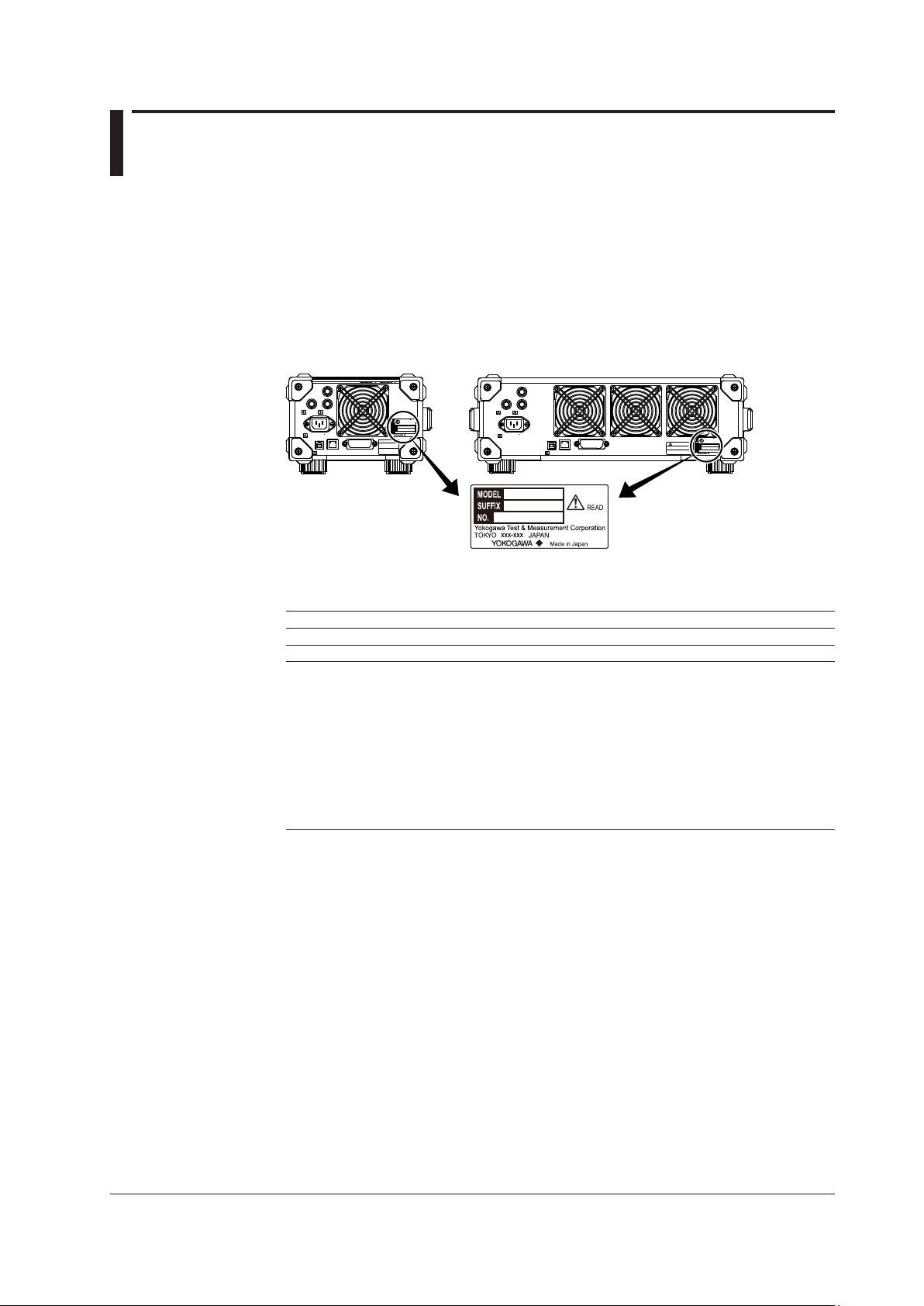
Checking the Package Contents
AQ2211 Frame Controller
AQ2212 Frame Controller
After receiving the product and opening the package, check the items described below.
If the wrong items have been delivered, if items are missing, or if there is a problem with
the appearance of the items, contact your nearest YOKOGAWA dealer. When contacting
the dealer from which you purchased the instrument, please give them the instrument
number.
Also, check that the model name and suffix code given on the name plate on the side
panel of the module are the same as those on your order.
REMOTE
INTERLOCK
170 VA MAX 50/60 Hz
100-240 V AC
TRIGGER
LINK/ACT
USB ETHERNET
IN
OUT
100 LINK
GP-IB
(IEEE488)
WARNING
Do not operate without reading
the safety precautions in the
user's manual.
DATE OF
MANUFACTURE
—
—
□□□□ □□ □□
MODEL
SUFFIX
NO
Made in Japan
REMOTE
INTERLOCK
100-240 V AC
580 VA MAX 50/60 Hz
IN
OUT
TRIGGER
LINK/ACT
100 LINK
ETHERNET
GP-IB
USB
(IEEE488)
AQ2211/AQ2212 Frame Controller
MODEL SUFFIX1Description
735101 AQ2211 Frame Controller (Three slots)
735102 AQ2212 Frame Controller (Nine slots)
Power cord
2
-D UL/CSA standard and PSE compliant, Maximum rated voltage: 125 V
-F VDE/Korean standard, Maximum rated voltage: 250 V
-R Australian standard, Maximum rated voltage: 250 V
-Q British standard, Maximum rated voltage: 250V
-H Chinese standard, Maximum rated voltage: 250 V
-N Brazilian standard, Maximum rated voltage: 250 V
-T Taiwanese standard, Maximum rated voltage: 125 V
-B Indian standard, Maximum rated voltage: 250 V
-U IEC Plug Type B, Maximum rated voltage: 250 V
-Y No power cord included.
3
WARNING
Do not operate without reading the
safety precautions in the user's manual.
DATE OF
MANUFACTURE
—
—
□□□□ □□ □□
MODEL
SUFFIX
NO
Made in Japan
IM 735101-01EN
1 For products whose suffix code contains “Z,” an exclusive manual may be included.
Please read it along with the standard manual.
2 Make sure that the attached power cord meets the designated standards of the country and area
that you are using it in.
3 Prepare a power cord that complies with the standard specified by the country or region that the
instrument will be used in.
No. (Instrument Number)
When contacting the dealer from which you purchased the instrument, please give them
the instrument number.
iii
Page 6
UL/CSA standard
A1006WD
Chinese standard
Brazilian standard
A1088WD
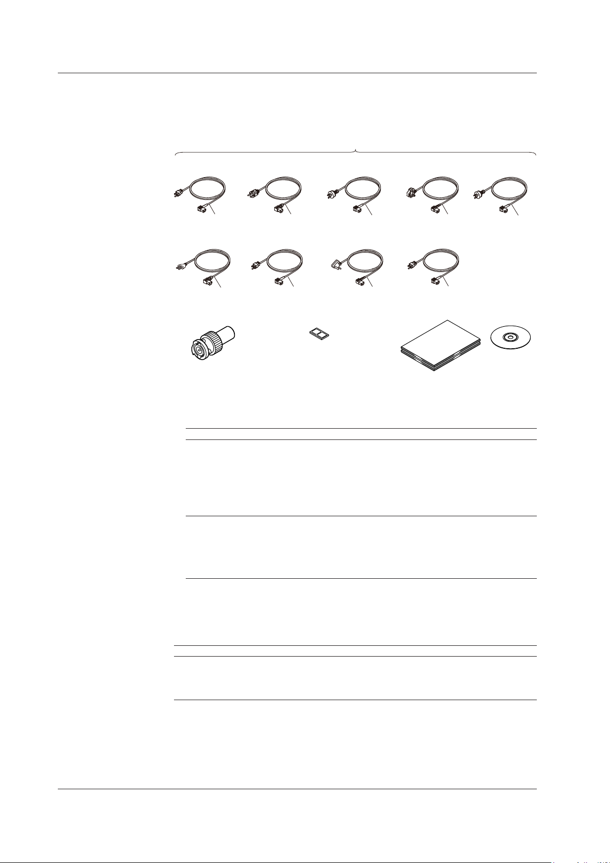
Power cord (one cord that matches the suffix code is included)
Checking the Package Contents
Standard Accessories
The standard accessories below are supplied with the instrument. Check that all contents
are present and that they are undamaged.
1
VDE/Korian standard
A1009WD
D
Taiwanese standard
A1100WD
N
Interlock connector plug
A1288JA 1 piece
F R
T
Rubber feet
A9088ZM 1 set
Australian standard
A1024WD
Indian standard
A1101WD
B
Manuals
• Printed manuals
British standard
A1054WD
Q
IEC Plug Type B
A1102WD
U
2
A1064WD
H
• Manual CD
Standard accessories are not covered by warranty of this instrument.
1 Make sure that the attached power cord meets the designated standards of the country and area
that you are using it in. If the suffix code is -Y, a power cord is not included.
2 Manuals
Item Model or Part No. Quantity Specifications and Notes
Printed manuals IM 735101-01EN 1 Startup Guide (this guide)
PIM 113-01Z2 1 List of worldwide contacts
IM 810518801-61E 1 For the AQ2200-601 10 Gbit/s BERT module
with the /M option
IM 810518801-62E 1 For the AQ2200-601 10 Gbit/s BERT module
with the /P1 option
IM 810518901-04E 1 For the AQ2200 series modules.
Manual CD B8085NZ 1 Contains PDFs of the user’s manuals
(For the types of manuals that CD contains,
see the next page.)
Printed manuals can be purchased separately.
Contact your nearest YOKOGAWA dealer to
purchase a copy.
iv
Optional Accessories (Sold separately)
The optional accessories below are available for purchase separately. For information
about ordering accessories, contact your nearest YOKOGAWA dealer.
Item Model or Part No. Specifications
AQ2200-901 blank panel 810518926 1-slot size
AQ2211 rack mount kit 735182-03 For mounting one AQ2211 to the left side of an EIA-
AQ2212 rack mount kit 735182-09 For mounting one AQ2212 to an EIA-standard rack.
Optional accesories(sold separately) are not covered by warranty of this instrument.
standard rack.
IM 735101-01EN
Page 7

Manual CD
The English folder in the manual CD contains the PDF files shown below. The CD also
contains Japanese manuals.
Manual Title Manual No.
AQ2200 Series Multi Application Test System
User’s Manual Startup Guide
AQ2200 Series Multi Application Test System
Frame and Module Operation User’s Manual
AQ2200 Series Multi Application Test System
Application Operation User’s Manual
AQ2200 Series Multi Application Test System
Communication Interface User’s Manual
To view the manuals above, you need Adobe Reader.
WARNING
Never play this manual CD in an audio CD player.
Doing so may cause loss of hearing or speaker damage due to the high-volume
sound that may be produced.
French
Checking the Package Contents
IM 735101-01EN
IM 735101-03EN
IM 735101-04EN
IM 735101-17EN
AVERTISSEMENT
Ce CD contient les manuels d’utilisation. Ne jamais insérer ce CD dans un lecteur
de CD audio. Cela pourrait entraîner une perte d’audition ou l’endommagement
des enceintes en raison du volume potentiellement élevé des sons produits.
IM 735101-01EN
v
Page 8
Safety Precautions
This product is designed to be used by a person with specialized knowledge.
This instrument is an IEC safety class I instrument (provided with a terminal for protective
earth grounding).
The general safety precautions described herein must be observed during all phases
of operation. If the instrument is used in a manner not specified in this manual, the
protection provided by the instrument may be impaired. This manual is part of the
product and contains important information. Store this manual in a safe place close to the
instrument so that you can refer to it immediately. Keep this manual until you dispose of
the instrument.
YOKOGAWA assumes no liability for the customer’s failure to comply with these
requirements.
The following symbols are used on this instrument.
Handle with care. Refer to the user’s manual or service manual. This symbol
appears on dangerous locations on the instrument which require special
instructions for proper handling or use. The same symbol appears in the
corresponding place in the manual to identify those instructions.
Alternating current
Power-on state
Power-off state
Laser radiation hazard
Power on
Power off
French
À manipuler délicatement. Toujours se reporter aux manuels d’utilisation et
d’entretien. Ce symbole a été apposé aux endroits dangereux de l’instrument pour
lesquels des consignes spéciales d’utilisation ou de manipulation ont été émises.
Le même symbole apparaît à l’endroit correspondant du manuel pour identifier les
consignes qui s’y rapportent.
Courant alternatif
Marche
Arrêt
Danger : Appareil laser à rayonnement.
Marche (alimentation)
Arrêt (alimentation)
vi
IM 735101-01EN
Page 9

Safety Precautions
Failure to comply with the precautions below could lead to injury or death or
damage to the instrument.
WARNING
Use the Instrument Only for Its Intended Purpose
This optical measuring instrument is designed to measure the optical characteristics
of light sources and evaluate their performance. Do not use this instrument for
anything other than as an optical measuring instrument.
Check the Physical Appearance
Do not use the instrument if there is a problem with its physical appearance.
Use the Correct Power Supply
Make sure that the power supply voltage matches the instrument’s rated supply
voltage and that it does not exceed the maximum voltage range of the power cord
to use.
Use the Correct Power Cord and Plug
To prevent electric shock or fire, be sure to use the power cord for the instrument.
The main power plug must be plugged into an outlet with a protective earth terminal.
Do not invalidate this protection by using an extension cord without protective earth
grounding. Further, do not use this power cord with other instruments.
Connect to a Protective Earth Terminal
To prevent electric shock, be sure to connect to a protective earth terminal before
turning on the frame controller’s power. The power cord to use is a three-prong
cord. Connect the power cord to a properly grounded three-prong outlet.
Do Not Impair the Protective Grounding
Never cut off the frame controller’s internal or external protective earth wire or
disconnect the wiring to the protective earth terminal. Doing so may result in
electric shock or damage to the instrument.
Do Not Operate with Defective Protective Grounding or Fuses
Do not operate the frame controller if its protective grounding or one of its fuses
might be defective. Check the grounding and the fuses before operating the frame
controller.
Do Not Operate in an Explosive Atmosphere
Do not operate the instrument in the presence of flammable gasses or vapors.
Doing so is extremely dangerous.
Do Not Remove the Covers or Disassemble or Alter the Instrument
Only qualified YOKOGAWA personnel may remove the covers and disassemble or
alter the instrument. The inside of the frame controller is dangerous because parts
of it have high voltages.
IM 735101-01EN
Ground the Instrument before Making External Connections
Securely connect the protective grounding before connecting to the item under
measurement or to an external control unit. Before touching a circuit, turn off its
power and check that it has no voltage.
vii
Page 10

Safety Precautions
Avoid Electric Shock When Using the Modules
Do not apply an input voltage that exceeds the maximum input voltage, withstand
voltage, or allowable surge voltage.
To prevent the possibility of electric shock, be sure to fasten the screws that are at
the bottom of the front panel of 2-slot and 3-slot modules. Otherwise, the electrical
and mechanical protection functions will not be activated.
Do not leave the modules connected to the instrument in environments in which a
voltage equal to or greater than the allowable surge voltage may occur.
Dispose the Instrument Properly
Do not throw this instrument into a fire to dispose of it. Doing so may cause the
instrument to explode, resulting in fire or personal injury.
The devices used in this instrument contain gallium arsenide (GaAs) and indium
phosphide (InP). When you dispose this instrument, you must separate it from
general industrial waste and household garbage, and dispose of it according to
local regulations.
Additionally, gallium arsenide powder and vapor are dangerous substances. Do not
burn, cut, crush, chemically disassemble, or otherwise destroy this instrument.
Install or Use the Instrument in Appropriate Locations
• Do not install or use the instrument outdoors or in locations subject to rain or
water.
• Install the instrument so that you can immediately remove the power cord if an
abnormal or dangerous condition occurs.
CAUTION
Operating Environment Limitations
This is a class A instrument designed for an industrial environment. Operation of
this equipment in a residential area can cause radio interference, in which case
users will be required to correct the interference.
French
AVERTISSEMENT
Utiliser l’instrument aux seules fins prévues
Cet instrument de mesure optique est prévu pour mesurer les caractéristiques
optiques des sources lumineuses et évaluer leur performance. Ne pas utiliser cet
instrument à d’autres fins que celles de mesure optique.
Inspecter l’apparence physique
Ne pas utiliser l’instrument si son intégrité physique semble être compromise.
Vérifier l’alimentation
Assurez-vous que la tension d’alimentation correspond à la tension d’alimentation
nominale de l’appareil et qu’elle ne dépasse pas la plage de tension maximale du
cordon d’alimentation à utiliser.
viii
Utiliser le cordon d’alimentation et la fiche adaptés
Pour éviter tout risque de choc électrique, utiliser exclusivement le cordon
d’alimentation prévu pour cet instrument. La fiche doit être branchée sur une prise
secteur raccordée à la terre. En cas d’utilisation d’une rallonge, celle-ci doit être
impérativement reliée à la terre. Par ailleurs, ne pas utiliser ce cordon d’alimentation
avec d’autres instruments.
IM 735101-01EN
Page 11

Safety Precautions
Brancher la prise de terre
Avant de mettre l’instrument sous tension, penser à brancher la prise de terre
pour éviter tout choc électrique. Le cordon d’alimentation à utiliser est un cordon
d’alimentation à trois broches. Brancher le cordon d’alimentation sur une prise de
courant à trois plots et mise à la terre.
Ne pas entraver la mise à la terre de protection
Ne jamais neutraliser le fil de terre interne ou externe, ni débrancher la borne
de mise à la terre. Cela pourrait entraîner un choc électrique ou endommager
l’instrument.
Ne pas utiliser avec un conducteur de terre ou un fusible défectueux
Ne pas utiliser l’instrument si le conducteur de terre ou le fusible est défectueux.
Vérifier le conducteur de terre et le fusible avant d’utiliser l’instrument.
Ne pas utiliser dans un environnement explosif
Ne pas utiliser l’instrument en présence de gaz ou de vapeurs inflammables.
Cela pourrait être extrêmement dangereux.
Ne pas retirer le capot, ni démonter ou modifier l’instrument
Seul le personnel YOKOGAWA qualifié est habilité à retirer le capot et à démonter
ou modifier l’instrument. Certains composants à l’intérieur de l’instrument sont à
haute tension et par conséquent, représentent un danger.
Relier l’instrument à la terre avant de le brancher sur des connexions
externes
Toujours relier l’instrument à la terre avant de le brancher aux appareils à mesurer
ou à une commande externe. Avant de toucher un circuit, mettre l’instrument hors
tension et vérifier l’absence de tension.
Éviter les chocs électriques lors de l’utilisation des modules.
Ne pas dépasser les valeurs maximales de tension d'entrée, de tension de
maintien ou de surtension admissible.
Pour éviter tout risque de choc électrique, veiller à serrer les vis situées au bas du
panneau avant des modules à 2 et 3 emplacements, à défaut de quoi les fonctions
de protection électrique et mécanique ne seront pas activées.
Ne pas laisser les modules branchés à l'instrument dans des environnements dans
lesquels la tension pourrait être égale ou supérieure à la surtension admissible.
Mettre l’instrument au rebut de manière adéquate.
Ne pas mettre l’instrument au rebut en le jetant au feu. Il risquerait d’exploser et de
provoquer un incendie ou de blesser quelqu’un.
Les dispositifs utilisés avec cet instrument contiennent de l’arséniure de gallium
(AsGa) et du phosphure d’indium (InP). Lors de la mise au rebut de l’instrument,
vous ne devez pas l’associer aux déchets industriels généraux ni aux déchets
domestiques, mais l’éliminer conformément aux réglementations locales.
De plus, la poudre et les vapeurs d’arséniure de gallium sont des substances
dangereuses. Ne pas brûler, couper, écraser, démonter chimiquement ou détruire
cet instrument.
IM 735101-01EN
ix
Page 12
Safety Precautions
Installer et utiliser l’instrument aux emplacements appropriés
• Ne pas installer, ni utiliser l’instrument à l’extérieur ou dans des lieux exposés à
la pluie ou à l’eau.
• Installer l’instrument de manière à pourvoir immédiatement le débrancher du
secteur en cas de fonctionnement anormal ou dangereux.
ATTENTION
Limitations relatives à l’environnement opérationnel
Ce produit est un produit de classe A (pour environnements industriels).
L’utilisation de ce produit dans un zone résidentielle peut entraîner une interférence
radio que l’utilisateur sera tenu de rectifier.
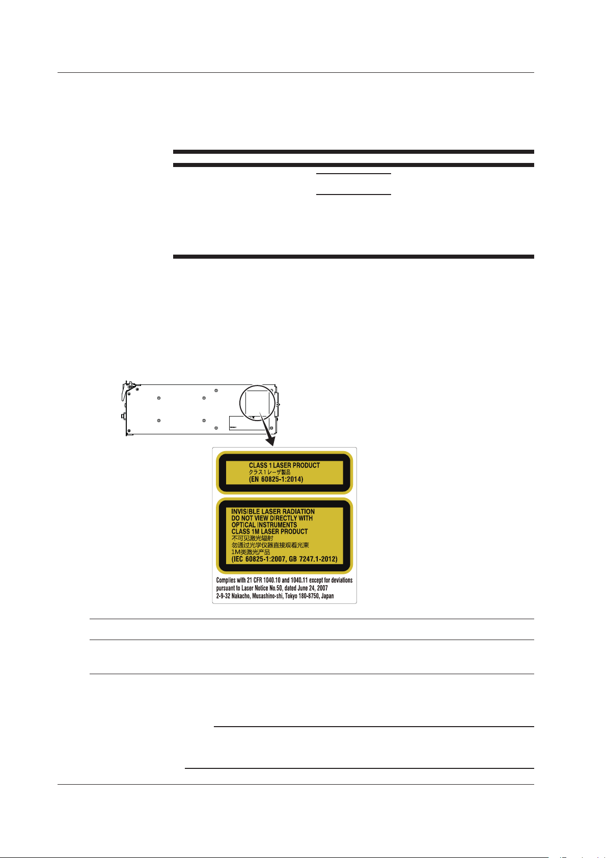
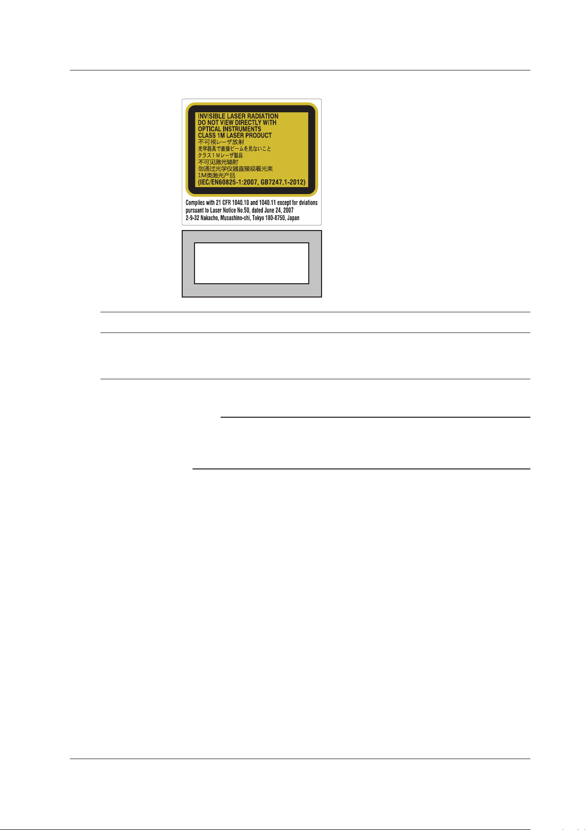
Safety Precautions for Laser Products
This instrument uses a laser light source. This instrument is a Class 1M laser product as
defined by IEC 60825-1:2007 Safety of Laser Products—Part1: Equipment Classification
and Requirements. In addition, this instrument complies with 21 CFR 1040.10 and
1040.11 except for deviations pursuant to Laser Notice No. 50, dated June 24, 2007.
AQ2200-112, AQ2200-131, and AQ2200-132 Modules
Laser Class 1 Label
Laser Class 1M Label
Using an optical instrument, such as a
loupe, magnifying glass, or microscope,
when observing the laser beam from a
distance of less than 100 mm may cause
eye injury.
Do not expose users of binoculars or
telescopes.
Skin exposure near aperture may cause
burns.
Model Class Laser Type 1Center Wavelength
AQ2200112 1, 1M DFB-Laser 1310 to 1650 nm 40 mW 9 μm 11.5 degree CW
AQ2200131 1, 1M ITLA 1527.60 to 1608.76 nm 63 mW 9 µm 11.5 degree CW
AQ2200132 1, 1M ITLA 1527.60 to 1608.76 nm 63 mW 9 µm 11.5 degree CW
1 Class 1: EN 60825-1:2014
Class 1M: IEC 60825-1:2007, GB 7247.1-2012
2 Under single fault conditions.
Maximum
Output Power
Mode Field
2
Diameter
Beam Divergence
(full angle at 1/e2)
Pulse Duration and
Repetition Rate
Note
Laser classes differ depending on the standard number and the year of the standard.
Take safety measures according to the laser class corresponding to the standard of the country
or region that the instrument will be used in.
x
IM 735101-01EN
Page 13
AQ2200-111, AQ2200-141, AQ2200-142, and AQ2200-136 Modules
Laser Class 1M Label
Using an optical instrument, such as a loupe,
CLASS 1 LASER PRODUCT
(IEC 60825-1:2007)
Safety Precautions
magnifying glass, or microscope, when
observing the laser beam from a distance of
less than 100 mm may cause eye injury.
Do not expose users of binoculars or
telescopes.
Skin exposure near aperture may cause
burns.
Laser Class 1 Label
Model Class Laser Type Center Wavelength
810518901 1M DFB-Laser 1310 to 1650 nm 40 mW
810518902 1 FP-Laser 1310/1550 nm 10 mW
810518903 1 FP-Laser 1310/1550 nm 10 mW
810518904 1M EC-Laser 1440 to 1640 nm 50.2 mW
1 Under single fault conditions.
Maximum
Output Power
Note
• Commercially available XFP transceivers installed in the AQ2200-641 XFP Interface Module
are not covered under warranty.
• For save handling of the laser, consult the user’s manual that came with the XFP
transceiver.
Mode Field
1
Diameter
9
m
μ
9
m
μ
9
m
μ
9
m
μ
Beam Divergence
(full angle at 1/e2)
11.5 degree CW
11.5 degree CW
11.5 degree CW
11.5 degree CW
Pulse Duration and
Repetition Rate
IM 735101-01EN
xi
Page 14
Sales in Each Country or Region
Waste Electrical and Electronic Equipment
Waste Electrical and Electronic Equipment (WEEE), Directive
(This directive is valid only in the EU.)
This product complies with the WEEE directive marking requirement. This marking
indicates that you must not discard this electrical/electronic product in domestic
household waste.
Product Category
With reference to the equipment types in the WEEE directive, this product is
classified as a “Monitoring and control instruments” product.
When disposing of products in the EU, contact your local Yokogawa Europe B.V.
office. Do not dispose in domestic household waste.
EU Battery Directive
EU Battery Directive
(This directive is valid only in the EU.)
Batteries are included in this product. This marking indicates they shall be sorted
out and collected as ordained in the EU battery directive.
Battery type: Lithium battery
You cannot replace batteries by yourself. When you need to replace batteries,
contact your local Yokogawa Europe B.V. office.
Authorized Representative in the EEA
Yokogawa Europe B.V. is the authorized representative of Yokogawa Test & Measurement
Corporation for this product in the EEA. To contact Yokogawa Europe B.V., see the
separate list of worldwide contacts, PIM 113-01Z2
About Environmental Standard
This instrument complies with environmental standard EN50581, but it will not comply
with the standard if an incompliant module is installed.
For details on compliant modules, see section 5.1.
關於在台灣銷售
This section is valid only in Taiwan.
關於在台灣所販賣的符合其相關規定的電源線
的網址進行查詢
https://tmi.yokogawa.com/support/service-warranty-quality/product-compliance/
A1100WD
的限用物質含量信息,請至下麵
xii
IM 735101-01EN
Page 15
Symbols and Notation Used in This Manual
Notes and Cautions
The notes and cautions in this manual are categorized using the following symbols.
Improper handling or use can lead to injury to the user or damage
to the instrument. This symbol appears on the instrument to indicate
that the user must refer to the user’s manual for special instructions.
The same symbol appears in the corresponding place in the user’s
manual to identify those instructions. In the manual, the symbol is
used in conjunction with the word “WARNING” or “CAUTION.”
WARNING
CAUTION
Calls attention to actions or conditions that could cause serious or
fatal injury to the user, and precautions that can be taken to prevent
such occurrences.
Calls attentions to actions or conditions that could cause light injury to
the user or damage to the instrument or user’s data, and precautions
that can be taken to prevent such occurrences.
French
AVERTISSEMENT
ATTENTION
Calls attention to information that is important for proper operation of
Note
Attire l’attention sur des gestes ou des conditions
Attire l’attention sur des gestes ou des conditions
susceptibles de provoquer des blessures graves (voire
mortelles), et sur les précautions de sécurité pouvant
prévenir de tels accidents.
susceptibles de provoquer des blessures légères ou
d’endommager l’instrument ou les données de l’utilisateur,
et sur les précautions de sécurité susceptibles de prévenir
de tels accidents.
the instrument.
IM 735101-01EN
Character Notations
Bold characters in procedural explanations are used to indicate panel keys and soft keys
that are used in the procedure and menu items that appear on the screen.
xiii
Page 16

Contents
List of Manual.....................................................................................................................................i
Checking the Package Contents...................................................................................................... iii
Safety Precautions ........................................................................................................................... vi
Sales in Each Country or Region .................................................................................................... xii
Symbols and Notation Used in This Manual .................................................................................. xiii
Module Model Name, Sux Code, and Accessories ..................................................................... xvi
Chapter 1 Component Names and Functions
1.1 Frame Controller .............................................................................................................. 1-1
1.2 Light Source Modules ....................................................................................................... 1-5
1.3 Optical Sensor Modules ................................................................................................. 1-10
1.4 ORL Module ................................................................................................................... 1-14
1.5 Attenuator Modules ........................................................................................................ 1-15
1.6 Optical Switch Modules .................................................................................................. 1-18
1.7 BERT Module ................................................................................................................. 1-21
1.8 Optical Modulator Modules ............................................................................................. 1-22
1.9 Optical Receiver Module ................................................................................................ 1-23
1.10 XFP Interface Module ..................................................................................................... 1-24
1.11 Transceiver I/F Module ................................................................................................... 1-25
1.12 SG Module ..................................................................................................................... 1-26
Chapter 2 Making Preparations for Measurements
2.1 Handling Precautions ....................................................................................................... 2-1
2.2 Installing the Instrument ................................................................................................... 2-3
2.3 Attaching and Removing Blank Panels ............................................................................ 2-7
2.4 Installing and Uninstalling Modules .................................................................................. 2-9
2.5 Connecting Cables ......................................................................................................... 2-12
2.6 Connecting and Disconnecting Connector Adapters ...................................................... 2-21
2.7 Connecting Optical Fiber Cables .................................................................................... 2-24
2.8 Connecting to the Power Supply .................................................................................... 2-25
Chapter 3 External Input and Output
3.1 Frame Controller .............................................................................................................. 3-1
3.2 Optical Sensor Modules ................................................................................................... 3-3
3.3 BERT Module ................................................................................................................... 3-4
3.4 Optical Modulator Module ................................................................................................ 3-8
3.5 Optical Receiver Module .................................................................................................. 3-9
3.6 XFP Interface Module ..................................................................................................... 3-10
3.7 Transceiver I/F Module ................................................................................................... 3-12
3.8 SG Module ..................................................................................................................... 3-15
xiv
IM 735101-01EN
Page 17

Contents
Chapter 4 Troubleshooting, Maintenance, and Inspection
4.1 Troubleshooting ................................................................................................................ 4-1
4.2 Error Messages ................................................................................................................ 4-6
4.3 Changing Modules ......................................................................................................... 4-16
4.4 Updating the Firmware ................................................................................................... 4-19
4.5 Routine Maintenance ..................................................................................................... 4-27
4.6 Recommended Replacement Parts ............................................................................... 4-34
4.7 Calibration ...................................................................................................................... 4-35
4.8 Disposing of the Instrument ............................................................................................ 4-35
Chapter 5 Specications
5.1 AQ2211/AQ2212 Frame Controller .................................................................................. 5-1
5.2 AQ2200-111 DFB-LD Module ........................................................................................... 5-4
5.3 AQ2200-112 LS Module ................................................................................................... 5-7
5.4 AQ2200-141/142 FP-LD Module ...................................................................................... 5-8
5.5 AQ2200-131/132 Grid TLS Module .................................................................................. 5-9
5.6 AQ2200-136 TLS Module ................................................................................................5-11
5.7 AQ2200-201 Interface Module ....................................................................................... 5-12
5.8 AQ2200-202 Interface Module ....................................................................................... 5-13
5.9 AQ2200-231/241 Optical Sensor Head .......................................................................... 5-14
5.10 AQ2200-232/242 Optical Sensor Head .......................................................................... 5-16
5.11 AQ2200-211 Sensor Module .......................................................................................... 5-18
5.12 AQ2200-215 Sensor Module .......................................................................................... 5-20
5.13 AQ2200-221 Sensor Module .......................................................................................... 5-22
5.14 AQ2200-271 ORL Module .............................................................................................. 5-24
5.15 AQ2200-311 ATTN Module ............................................................................................. 5-25
5.16 AQ2200-311A/312 ATTN Module ................................................................................... 5-26
5.17 AQ2200-331/332 ATTN Module ..................................................................................... 5-27
5.18 AQ2200-342 DUAL ATTN Module .................................................................................. 5-28
5.19 AQ2200-411/412 OSW Module ...................................................................................... 5-29
5.20 AQ2200-421 OSW Module ............................................................................................. 5-30
5.21 AQ2200-601 10 Gbit/s BERT Module ............................................................................ 5-31
5.22 AQ2200-621/622 10 Gbit/s Optical Modulator ............................................................... 5-34
5.23 AQ2200-631 10 Gbit/s Optical Receiver ........................................................................ 5-35
5.24 AQ2200-641 XFP Interface Module ............................................................................... 5-36
5.25 AQ2200-642 Transceiver I/F Module ............................................................................. 5-37
5.26 AQ2200-651 SG Module ................................................................................................ 5-39
5.27 External Dimensions ...................................................................................................... 5-40
1
2
3
4
5
Index
Index
IM 735101-01EN
xv
Page 18

Module Model Name, Suffix Code, and Accessories
AQ2200-111 DFB-LD Module
Model Suffix Code Description
810518901 —
Wavelength -Mxxxx See section 5.2 for the list of supported
wavelengths
-W1310 1310 nm
-W1490 1490 nm
Optical connector -FCA FC/Angled PC connector
Optical output level -P10 10 mW optical output
-P20 20 mW optical output
Optical fiber -SMF SM fiber
-PMF PM fiber
External modulation -MODN No external modulation
-MODS External modulation (sine)
-MODC External modulation (chop)
Standard Accessories
The standard accessories below are supplied with the instrument.
Item Model or Part No. Quantity Notes
Protective cap* — 1 Green
Protective cap* — 1 White (for use with the external
modulation option)
User’s manual IM 810518901-04E 1 Read before using the instrument
*: Already attached to the module
AQ2200-112 LS Module
Model Suffix Code Description
AQ2200112 —
Wavelength -D300 DFB-LD, 1310 nm
-D500 DFB-LD, 1550 nm
-D600 DFB-LD, 1625 nm
-D700 DFB-LD, 1650 nm
-D3D3 DFB-LD, Ch1: 1310 nm, Ch2: 1310 nm
-D3D5 DFB-LD, Ch1: 1310 nm, Ch2: 1550 nm
-D3D6 DFB-LD, Ch1: 1310 nm, Ch2: 1625 nm
-D3D7 DFB-LD, Ch1: 1310 nm, Ch2: 1650 nm
-D5D5 DFB-LD, Ch1: 1550 nm, Ch2: 1550 nm
-D5D6 DFB-LD, Ch1: 1550 nm, Ch2: 1625 nm
-D5D7 DFB-LD, Ch1: 1550 nm, Ch2: 1650 nm
-D6D6 DFB-LD, Ch1: 1625 nm, Ch2: 1625 nm
-D6D7 DFB-LD, Ch1: 1625 nm, Ch2: 1650 nm
-D7D7 DFB-LD, Ch1: 1650 nm, Ch2: 1650 nm
(Firmware version 3.08 and later)
Standard Accessories
The standard accessories below are supplied with the instrument.
Item Model or Part No. Quantity Notes
Protective cap* — 1 1-channel model (-D300, -D500,
-D600, -D700)
2 2-channel model (-D3D3, -D3D5,
-D3D6, -D3D7, -D5D5, -D5D6,
-D5D7, -D6D6, -D6D7, -D7D7)
User’s manual IM 810518901-04E 1 Read before using the instrument
*: Already attached to the module
xvi
IM 735101-01EN
Page 19

Module Model Name, Suffix Code, and Accessories
AQ2200-141 FP-LD Module
Model Suffix Code Description
810518902 —
Wavelength -W1310 1310 nm
-W1550 1550 nm
Optical connector /FCC AQ9441 (FC) universal adapter
/SCC AQ9441 (SC) universal adapter
Standard Accessories
The standard accessories below are supplied with the instrument.
Item Model or Part No. Quantity Notes
Protective cap* — 1
User’s manual IM 810518901-04E 1 Read before using the instrument
*: Already attached to the module
Optional Accessories
The optional accessories below are available for purchase separately.
Item Model Notes
AQ9441 (FC) universal adapter 813917321-FCC FC connector
AQ9441 (SC) universal adapter 813917321-SCC SC connector
AQ2200-142 DUAL FP-LD Module
Model Suffix Code Description
810518903 —
Wavelength -W135D 1310/1550 nm
Optical connector /FCC AQ9441 (FC) universal adapter
/SCC AQ9441 (SC) universal adapter
Standard Accessories
The standard accessories below are supplied with the instrument.
Item Model or Part No. Quantity Notes
Protective cap* — 1
User’s manual IM 810518901-04E 1 Read before using the instrument
*: Already attached to the module
Optional Accessories
The optional accessories below are available for purchase separately.
Item Model Notes
AQ9441 (FC) universal adapter 813917321-FCC FC connector
AQ9441 (SC) universal adapter 813917321-SCC SC connector
IM 735101-01EN
xvii
Page 20

Module Model Name, Suffix Code, and Accessories
AQ2200-131 Grid TLS Module
Model Suffix Code Description
AQ2200131 —
Wavelength -C C-band
-L L-band
LD type -T4 Standard type
-T2 Advanced type (Fine tuning)
-T6 Advanced type (Fine tuning)
Optical fiber -PA PM fiber
Optical connector -FCC FC/PC connector
-FCA FC/Angled PC connector
(-T2 and -T4:Firmware version 3.00 and later)
(-T6:Firmware version 3.05 and later)
Standard Accessories
The standard accessories below are supplied with the instrument.
Item Model or Part No. Quantity Notes
Protective cap* — 1
User’s manual IM 810518901-04E 1 Read before using the instrument
*: Already attached to the module
AQ2200-132 Grid TLS Module
Model Suffix Code Description
AQ2200132 —
Wavelength -CC CH1: C-band, CH2: C-band
-LL CH1: L-band, CH2: L-band
-CL CH1: C-band, CH2: L-band
LD type -T4 Standard type
-T2 Advanced type (Fine tuning)
-T6 Advanced type (Fine tuning)
Optical fiber -PA PM fiber
Optical connector -FCC FC/PC connector
-FCA FC/Angled PC connector
(-T2 and -T4:Firmware version 3.00 and later)
(-T6:Firmware version 3.05 and later)
Standard Accessories
The standard accessories below are supplied with the instrument.
Item Model or Part No. Quantity Notes
Protective cap* — 1
User’s manual IM 810518901-04E 1 Read before using the instrument
*: Already attached to the module
AQ2200-136 TLS Module
Model Suffix Code Description
810518904 —
Optical connector -FCA FC/Angled PC connector
Optical fiber -SMF SM fiber
Wavelength -WLSTD Changeable
Standard Accessories
The standard accessories below are supplied with the instrument.
Item Model or Part No. Quantity Notes
Protective cap (small)* — 2 Green
Protective cap (large)* — 1
User’s manual IM 810518901-04E 1 Read before using the instrument
*: Already attached to the module
xviii
IM 735101-01EN
Page 21

AQ2200-201 Interface Module
Optical sensor head
Analog out plug
955-230002662
Model Suffix Code Description
810518905 —
Standard Accessories
The standard accessories below are supplied with the instrument.
Item Model or Part No. Quantity Notes
Analog out plug 955-230002662 1
Optical sensor head
connector cable
User’s manual IM 810518901-04E 1 Read before using the instrument
Optional Accessory
The following optional accessory is available for purchase separately.
Item Part No. Notes
Analog out plug 955-230002662
Module Model Name, Suffix Code, and Accessories
955-850002026 1
connector cable
955-850002026
AQ2200-202 Interface Module
Model Suffix Code Description
AQ2200202 —
(Firmware version 3.05 and later)
Standard Accessories
The standard accessories below are supplied with the instrument.
Item Model or Part No. Quantity Notes
User’s manual IM 810518901-04E 1 Read before using the instrument
IM 735101-01EN
xix
Page 22

Module Model Name, Suffix Code, and Accessories
AQ2200-231 Optical Sensor Head
Model Suffix Code Description
810518906 Large-aperture, long-wavelength sensor
Connector adapter /FCC AQ9355C (FC) connector adapter with a light shielding cap
/SCC AQ9335C (SC) connector adapter with a light shielding cap
/STC AQ9335C (ST) connector adapter with a light shielding cap
Standard Accessories
The standard accessories below are supplied with the instrument.
Item Model or Part No. Quantity Notes
Protective cap* — 1
Ring* — 1
User’s manual IM 810518901-04E 1 Read before using the instrument
*: Already attached to the module
Optional Accessories
The optional accessories below are available for purchase separately.
Item Model or Part No. Notes
AQ9335C (FC) connector adapter 810518909-FCC FC connector
AQ9335C (SC) connector adapter 810518910-SCC SC connector
AQ9335C (ST) connector adapter 810518911-STC ST connector
AQ9335C (LC) connector adapter M3407JD LC connector with a dust protection cap
AQ9335C (MU) connector adapter M3407JE MU connector with a dust protection cap
Light shielding cap (FC) 810518912-FCC Light shielding cap for an FC connector
Light shielding cap (SC) 810518913-SCC Light shielding cap for an SC connector
Light shielding cap (ST) 810518914-STC Light shielding cap for an ST connector
AQ9346 tape fiber adapter 810517917
AQ9302 (125) bare fiber adapter 819705500-0125
AQ9440B MT connector 810517921-B 2, 4, 8, and 12 cores
Dust protection cap (LC) M3407HD Dust protection cap for an LC connector
Dust protection cap (MU) M3407HE Dust protection cap for an MU connector
xx
IM 735101-01EN
Page 23

Module Model Name, Suffix Code, and Accessories
AQ2200-232 Optical Sensor Head
Model Suffix Code Description
AQ2200232 Large-aperture, long-wavelength sensor
Connection cable -L1 Length: 1 m
-L4 Length: 4 m
Connector adapter /FCC AQ9355C (FC) connector adapter with a light shielding cap
/SCC AQ9335C (SC) connector adapter with a light shielding cap
/LCC AQ9335C (LC) connector adapter with a dust protection cap
/MUC AQ9335C (MU) connector adapter with a dust protection cap
(Firmware version 3.05 and later)
Standard Accessories
The standard accessories below are supplied with the instrument.
Item Model or Part No. Quantity Notes
Protective cap* — 1
Ring* — 1
Connection cable A1638WL 1 For -L1 model (cable length: 1 m)
A1639WL 1 For -L4 model (cable length: 4 m)
User’s manual IM 810518901-04E 1 Read before using the instrument
*: Already attached to the module
Optional Accessories
The optional accessories below are available for purchase separately.
Item Model or Part No. Notes
AQ9335C (FC) connector adapter 810518909-FCC FC connector
AQ9335C (SC) connector adapter 810518910-SCC SC connector
AQ9335C (LC) connector adapter M3407JD LC connector with a dust protection cap
AQ9335C (MU) connector adapter M3407JE MU connector with a dust protection cap
Light shielding cap (FC) 810518912-FCC Light shielding cap for an FC connector
Light shielding cap (SC) 810518913-SCC Light shielding cap for an SC connector
Connection cable A1638WL Cable le ght: 1 m
Connection cable A1639WL Cable le ght: 4 m
Dust protection cap (LC) M3407HD Dust protection cap for an LC connector
Dust protection cap (MU) M3407HE Dust protection cap for an MU connector
IM 735101-01EN
xxi
Page 24

Module Model Name, Suffix Code, and Accessories
AQ2200-241 Optical Sensor Head
Model Suffix Code Description
810518907 Large-aperture, short-wavelength sensor
Connector adapter /FCC AQ9355C (FC) connector adapter with a light shielding cap
/SCC AQ9335C (SC) connector adapter with a light shielding cap
/STC AQ9335C (ST) connector adapter with a light shielding cap
Standard Accessories
The standard accessories below are supplied with the instrument.
Item Model or Part No. Quantity Notes
Protective cap* — 1
Ring* — 1
User’s manual IM 810518901-04E 1 Read before using the instrument
*: Already attached to the module
Optional Accessories
The optional accessories below are available for purchase separately.
Item Model or Part No. Notes
AQ9335C (FC) connector adapter 810518909-FCC FC connector
AQ9335C (SC) connector adapter 810518910-SCC SC connector
AQ9335C (ST) connector adapter 810518911-STC ST connector
AQ9335C (LC) connector adapter M3407JD LC connector with a dust protection cap
AQ9335C (MU) connector adapter M3407JE MU connector with a dust protection cap
Light shielding cap (FC) 810518912-FCC Light shielding cap for an FC connector
Light shielding cap (SC) 810518913-SCC Light shielding cap for an SC connector
Light shielding cap (ST) 810518914-STC Light shielding cap for an ST connector
AQ9346 tape fiber adapter 810517917
AQ9302 (125) bare fiber adapter 819705500-0125
AQ9440B MT connector 810517921-B 2, 4, 8, and 12 cores
Dust protection cap (LC) M3407HD Dust protection cap for an LC connector
Dust protection cap (MU) M3407HE Dust protection cap for an MU connector
xxii
IM 735101-01EN
Page 25

Module Model Name, Suffix Code, and Accessories
AQ2200-242 Optical Sensor Head
Model Suffix Code Description
AQ2200242 Large-aperture, short-wavelength sensor
Connection cable -L1 Length: 1 m
-L4 Length: 4 m
Connector adapter /FCC AQ9355C (FC) connector adapter with a light shielding cap
/SCC AQ9335C (SC) connector adapter with a light shielding cap
/LCC AQ9335C (LC) connector adapter with a dust protection cap
/MUC AQ9335C (MU) connector adapter with a dust protection cap
(Firmware version 3.06 and later)
Standard Accessories
The standard accessories below are supplied with the instrument.
Item Model or Part No. Quantity Notes
Protective cap* — 1
Ring* — 1
Connection cable A1638WL 1 For -L1 model (cable length: 1 m)
A1639WL 1 For -L4 model (cable length: 4 m)
User’s manual IM 810518901-04E 1 Read before using the instrument
*: Already attached to the module
Optional Accessories
The optional accessories below are available for purchase separately.
Item Model or Part No. Notes
AQ9335C (FC) connector adapter 810518909-FCC FC connector
AQ9335C (SC) connector adapter 810518910-SCC SC connector
AQ9335C (LC) connector adapter M3407JD LC connector with a dust protection cap
AQ9335C (MU) connector adapter M3407JE MU connector with a dust protection cap
Light shielding cap (FC) 810518912-FCC Light shielding cap for an FC connector
Light shielding cap (SC) 810518913-SCC Light shielding cap for an SC connector
Connection cable A1638WL Cable le ght: 1 m
Connection cable A1639WL Cable le ght: 4 m
Dust protection cap (LC) M3407HD Dust protection cap for an LC connector
Dust protection cap (MU) M3407HE Dust protection cap for an MU connector
IM 735101-01EN
xxiii
Page 26

Analog out plug
955-230002662
Module Model Name, Suffix Code, and Accessories
AQ2200-211 Sensor Module
Model Suffix Code Description
810518908 Highly sensitive, long-wavelength sensor
Connector adapter /FCC AQ9447 (FC) connector adapter with a light shielding cap
/SCC AQ9447 (SC) connector adapter with a light shielding cap
/STC AQ9447 (ST) connector adapter with a light shielding cap
Standard Accessories
The standard accessories below are supplied with the instrument.
Item Model or Part No. Quantity Notes
Protective cap* — 1
Analog out plug 955-230002662 1
User’s manual IM 810518901-04E 1 Read before using the instrument
*: Already attached to the module
Optional Accessories
The optional accessories below are available for purchase separately.
Item Model or Part No. Notes
AQ9447 (FC) connector adapter 810804602-FCC FC connector
AQ9447 (SC) connector adapter 810804602-SCC SC connector
AQ9447 (ST) connector adapter 810804602-STC ST connector
Light shielding cap (FC) 810518912-FCC Light shielding cap for an FC connector
Light shielding cap (SC) 810518913-SCC Light shielding cap for an SC connector
Light shielding cap (ST) 810518914-STC Light shielding cap for an ST connector
AQ9346 tape fiber adapter 810517917
AQ9302 (125) bare fiber adapter 819705500-0125
AQ9440B MT connector 810517921-B 2, 4, 8, and 12 cores
Analog out plug 955-230002662
xxiv
IM 735101-01EN
Page 27

Module Model Name, Suffix Code, and Accessories
AQ2200-215 Sensor Module
Model Suffix Code Description
735125 High power sensor
Connector adapter -NON No connector adapter
-FCC AQ9335C (FC) connector adapter with a light shielding cap
-SCC AQ9335C (SC) connector adapter with a light shielding cap
-STC AQ9335C (ST) connector adapter with a light shielding cap
-LCC AQ9335C (LC) connector adapter with a dust protection cap
-MUC AQ9335C (MU) connector adapter with a dust protection cap
Standard Accessories
The standard accessories below are supplied with the instrument.
Item Model or Part No. Quantity Notes
Ring* — 1
Protective cover* — 1
User’s manual IM 810518901-04E 1 Read before using the instrument
*: Already attached to the module
Optional Accessories
The optional accessories below are available for purchase separately.
Item Model or Part No. Notes
AQ9335C (FC) connector adapter 810518909-FCC FC connector
AQ9335C (SC) connector adapter 810518910-SCC SC connector
AQ9335C (ST) connector adapter 810518911-STC ST connector
AQ9335C (LC) connector adapter M3407JD LC connector with a dust protection cap
AQ9335C (MU) connector adapter M3407JE MU connector with a dust protection cap
Light shielding cap (FC) 810518912-FCC Light shielding cap for an FC connector
Light shielding cap (SC) 810518913-SCC Light shielding cap for an SC connector
Light shielding cap (ST) 810518914-STC Light shielding cap for an ST connector
Dust protection cap (LC) M3407HD Dust protection cap for an LC connector
Dust protection cap (MU) M3407HE Dust protection cap for an MU connector
IM 735101-01EN
xxv
Page 28

Module Model Name, Suffix Code, and Accessories
AQ2200-221 Sensor Module
Model Suffix Code Description
735122 Two-channel, long-wavelength sensor
Connector adapter -NON No connector adapter
-FCC AQ9335C (FC) connector adapter with a light shielding cap
-SCC AQ9335C (SC) connector adapter with a light shielding cap
-STC AQ9335C (ST) connector adapter with a light shielding cap
-LCC AQ9335C (LC) connector adapter with a dust protection cap
-MUC AQ9335C (MU) connector adapter with a dust protection cap
Standard Accessories
The standard accessories below are supplied with the instrument.
Item Model or Part No. Quantity Notes
Ring* — 2
Protective cover* — 2
User’s manual IM 810518901-04E 1 Read before using the instrument
*: Already attached to the module
Optional Accessories
The optional accessories below are available for purchase separately.
Item Model or Part No. Notes
AQ9335C (FC) connector adapter 810518909-FCC FC connector
AQ9335C (SC) connector adapter 810518910-SCC SC connector
AQ9335C (ST) connector adapter 810518911-STC ST connector
AQ9335C (LC) connector adapter M3407JD LC connector with a dust protection cap
AQ9335C (MU) connector adapter M3407JE MU connector with a dust protection cap
Light shielding cap (FC) 810518912-FCC Light shielding cap for an FC connector
Light shielding cap (SC) 810518913-SCC Light shielding cap for an SC connector
Light shielding cap (ST) 810518914-STC Light shielding cap for an ST connector
Dust protection cap (LC) M3407HD Dust protection cap for an LC connector
Dust protection cap (MU) M3407HE Dust protection cap for an MU connector
AQ2200-271 ORL Module
Model Suffix Code Description
735185 —
Optical fiber -SA SMF (10/125)
Standard Accessories
The standard accessories below are supplied with the instrument.
Item Model or Part No. Quantity Notes
Protective cap* — 3
User’s manual IM 810518901-04E 1 Read before using the instrument
*: Already attached to the module
Optional Accessories
The optional accessories below are available for purchase separately.
Item Part No. Notes
ORL master cord 955-300001169 FC connector
ORL master cord 955-300001170 SC connector
ORL master cord 955-300900506 Open
xxvi
IM 735101-01EN
Page 29

Module Model Name, Suffix Code, and Accessories
AQ2200-311 ATTN Module
Model Suffix Code Description
810518915 —
Optical connector -FCC FC/PC connector
-SCC SC/PC connector
-FCA FC/Angled PC connector
-SCA SC/Angled PC connector
Monitor port option /MON Monitor port included
Standard Accessories
The standard accessories below are supplied with the instrument.
Item Model or Part No. Quantity Notes
Protective cap* — 2
— 3 When the monitor port (/MON) is
available
User’s manual IM 810518901-04E 1 Read before using the instrument
*: Already attached to the module
AQ2200-311A ATTN Module
Model Suffix Code Description
735131 —
Optical fiber -SA SMF (10/125)
-G5 MMF (50/125)
-G6 MMF (62.5/125)
Optical connector -FCC FC/PC connector
-SCC SC/PC connector
Monitor port option /MON Monitor port included
Standard Accessories
The standard accessories below are supplied with the instrument.
Item Model or Part No. Quantity Notes
Protective cap* — 2
— 3 When the monitor port (/MON) is
available
User’s manual IM 810518901-04E 1 Read before using the instrument
*: Already attached to the module
AQ2200-312 ATTN Module
Model Suffix Code Description
AQ2200312 —
Optical fiber -SA SMF (10/125)
-G5 MMF (50/125)
-G6 MMF (62.5/125)
Optical connector -FCC FC/PC connector
-SCC SC/PC connector
Monitor port option /MON Monitor port included
(Firmware version 3.04 and later)
Standard Accessories
The standard accessories below are supplied with the instrument.
Item Model or Part No. Quantity Notes
Protective cap* — 2
— 3 When the monitor port (/MON) is
available
User’s manual IM 810518901-04E 1 Read before using the instrument
*: Already attached to the module
IM 735101-01EN
xxvii
Page 30

Module Model Name, Suffix Code, and Accessories
AQ2200-331 ATTN Module
Model Suffix Code Description
735133 Built-in monitor power meter
Optical fiber -SA SMF
Optical connector -FCC FC/PC connector
Standard Accessories
The standard accessories below are supplied with the instrument.
Item Model or Part No. Quantity Notes
Protective cap* — 2
User’s manual IM 810518901-04E 1 Read before using the instrument
*: Already attached to the module
-G5 MMF (GI 50/125)
-G6 MMF (GI 62.5/125)
-SCC SC/PC connector
AQ2200-332 ATTN Module
Model Suffix Code Description
AQ2200332 Built-in monitor power meter
Optical fiber -SA SMF
-G5 MMF (GI 50/125)
-G6 MMF (GI 62.5/125)
Optical connector -FCC FC/PC connector
-SCC SC/PC connector
(Firmware version 3.04 and later)
Standard Accessories
The standard accessories below are supplied with the instrument.
Item Model or Part No. Quantity Notes
Protective cap* — 2
User’s manual IM 810518901-04E 1 Read before using the instrument
*: Already attached to the module
AQ2200-342 DUAL ATTN Module
Model Suffix Code Description
AQ2200342 Built-in monitor power meters
Optical fiber -SA SMF
Optical connector -FCC FC/PC connector
-FCA FC/Angled PC connector
(Firmware version 3.01 and later)
Standard Accessories
The standard accessories below are supplied with the instrument.
Item Model or Part No. Quantity Notes
Protective cap* — 1
User’s manual IM 810518901-04E 1 Read before using the instrument
*: Already attached to the module
xxviii
IM 735101-01EN
Page 31

Module Model Name, Suffix Code, and Accessories
AQ2200-411 OSW Module
Model Suffix Code Description
735141 1×4 or 1×8
Port configuration -04 1×4
-08 1×8
Optical fiber -SA SMF
-G5 MMF (GI 50/125)
-G6 MMF (GI 62.5/125)
Optical connector -FCC FC/PC connector
-SCC SC/PC connector
Standard Accessories
The standard accessories below are supplied with the instrument.
Item Model or Part No. Quantity Notes
Protective cap* — 5 When the port configuration is 1×4
— 9 When the port configuration is 1×8
User’s manual IM 810518901-04E 1 Read before using the instrument
*: Already attached to the module
AQ2200-412 OSW Module
Model Suffix Code Description
735143 1×16
Port configuration -16 1×16
Optical fiber -SA SMF
-G5 MMF (GI 50/125)
Optical connector -FCC FC/PC connector
-SCC SC/PC connector
Standard Accessories
The standard accessories below are supplied with the instrument.
Item Model or Part No. Quantity Notes
Protective cap* — 17
User’s manual IM 810518901-04E 1 Read before using the instrument
*: Already attached to the module
AQ2200-421 OSW Module
Model Suffix Code Description
735142 1×2 or 2×2
Port configuration -21 1×2
-22 2×2
Optical fiber -SA SMF
-G5 MMF (GI 50/125)
-G6 MMF (GI 62.5/125)
Optical connector -FCC FC/PC connector
-SCC SC/PC connector
Standard Accessories
The standard accessories below are supplied with the instrument.
Item Model or Part No. Quantity Notes
Protective cap* — 6 When the port configuration is 1×2
— 8 When the port configuration is 2×2
User’s manual IM 810518901-04E 1 Read before using the instrument
*: Already attached to the module
IM 735101-01EN
xxix
Page 32

Module Model Name, Suffix Code, and Accessories
AQ2200-601 10 Gbit/s BERT Module
Model Suffix Code Description
810518801 —
Options /M PC software for creating 64 Mbit program patterns
/P1 PC software for creating SDH/SONET frame patterns
Standard Accessories
The standard accessories below are supplied with the instrument.
Item Model or Part No. Quantity Notes
Protective cap* — 5
Terminator for circuit
protection*
User’s manual IM 810518901-04E 1 Read before using the instrument
*: Already attached to the module
AQ2200-621 10 Gbit/s Optical Modulator
Model Suffix Code Description
810518802
Crystal orientation of
the LN modulator
Optical connector -S SC connector
Cable /P
— 6
1.55
-A X-cut
-B Z-cut
-F FC connector
PMF (FC-SC) for 1.5
/U U-link coaxial cable
m
μ
m
μ
Standard Accessories
The standard accessories below are supplied with the instrument.
Item Model or Part No. Quantity Notes
Protective cap* — 2
Terminator for circuit
protection*
User’s manual IM 810518901-04E 1 Read before using the instrument
*: Already attached to the module
— 1
AQ2200-622 10 Gbit/s Optical Modulator
Model Suffix Code Description
810518804
Crystal orientation of
the LN modulator
Optical connector -S SC connector
Cable /P
-A X-cut
-B Z-cut
-F FC connector
/U U-link coaxial cable
Standard Accessories
The standard accessories below are supplied with the instrument.
Item Model or Part No. Quantity Notes
Protective cap* — 2
Terminator for circuit
protection*
User’s manual IM 810518901-04E 1 Read before using the instrument
*: Already attached to the module
— 1
1.31
m
μ
PMF (FC-SC) for 1.3
m
μ
xxx
IM 735101-01EN
Page 33

Module Model Name, Suffix Code, and Accessories
AQ2200-631 10 Gbit/s Optical Receiver
Model Suffix Code Description
810518803
Optical connector -S SC connector
-F FC connector
Cable /U U-link coaxial cable
1.31/1.55
m
μ
Standard Accessories
The standard accessories below are supplied with the instrument.
Item Model or Part No. Quantity Notes
Protective cap* — 1
Terminator for circuit
protection*
User’s manual IM 810518901-04E 1 Read before using the instrument
*: Already attached to the module
— 1
AQ2200-641 XFP Interface Module
Model Suffix Code Description
735161 —
Standard Accessories
The standard accessories below are supplied with the instrument.
Item Model or Part No. Quantity Notes
Protective cap* — 3
Terminator for circuit
protection*
User’s manual IM 810518901-04E 1 Read before using the instrument
*: Already attached to the module
— 2
AQ2200-642 Transceiver I/F Module
Model Suffix Code Description
735162 —
Standard Accessory
The standard accessory below is supplied with the instrument.
Item Model or Part No. Quantity Notes
User’s manual IM 810518901-04E 1 Read before using the instrument
AQ2200-651 SG Module
Model Suffix Code Description
735163 —
Standard Accessories
The standard accessories below are supplied with the instrument.
Item Model or Part No. Quantity Notes
Protective cap* — 1
Terminator for circuit
protection*
User’s manual IM 810518901-04E 1 Read before using the instrument
*: Already attached to the module
— 6
IM 735101-01EN
xxxi
Page 34

Display screen
Hard keys
Power switch
Used when you connect a USB
Used to remotely control the instrument.
Power inlet
Used to remotely control the instrument.
Chapter 1 Component Names and Functions
1.1 Frame Controller
Three-Slot Type
Front
Module installation slots
Hold AQ2200 series modules.
1 2 3
DETAIL
SUMMARY
FILE
PRTSC
7
4
1
0
Displays settings and measured results.
Soft keys
Used when you control the
frame controller or a module.
FRAME CONTROLLER
AQ2211
8
SLOT SLOT
5
HOLD
2
MACRO
PRESET
9
6
APPLI
3
SYSTEM
SHIFT
CANCEL
POWER
ENTER
USB Port (type A)
memory device.
USB
1
Component Names and Functions
Back
This is the connector for the power source.
REMOTE INTERLOCK connector
(For details, see section 3.1.)
TRIGGER-OUT connector
(For details, see section 3.1.)
TRIGGER-IN connector
IN
OUT
REMOTE
TRIGGER
INTERLOCK
100-240 V AC
170 VA MAX 50/60 Hz
LINK/ACT
100 LINK
USB ETHERNET
(
IEEE488
GP-IB
)
(For details, see section 3.1.)
Xxxxxxx xxxx xxxxx xxxx
xxxx xxxxx xxxx xxxx xxx
xxxxx xxxxxx xxx xxxx
xxxxxxx xxxxx xxxxxxx
Xxxx XX, XXXX
X-X-XX Xxxxxxxx,
Xxxxxxx-xxx, Xxxxxx,
XXX-XXXX, Xxxxx
DATE OF
MANUFACTURE
MODEL
SUFFIX
NO
WARNING
Do not operate without reading
the safety precautions in the
user` s manual.
GP-IB connector
IM 735101-01EN
Ethernet port
Used to remotely control the instrument.
USB port (type B)
1-1
Page 35

Soft keys
Used when you connect a USB memory device.
Used to remotely control the instrument.
REMOTE INTERLOCK connector
1.1 Frame Controller
Nine-Slot Type
Front
Used when you control the frame controller or a module.
Display screen
Displays settings and measured results.
Module installation slots
Hold AQ2200 series modules.
1 2 3 4 5 6 7 8 9
USB port (type A)
AQ2212
8
7
SLOT SLOT
DETAIL
4
5
SUMMARY
HOLD
2
1
FILE
MACRO
0
PRTSC
PRESET
Hard keys
Power switch
FRAME CONTROLLER
9
6
APPLI
3
CANCEL
CANCEL
SYSTEM
SHIFT
POWER
ENTER
ENTER
USB
Back
(For details, see section 3.1.)
REMOTE
INTERLOCK
100-240 V AC
580 VA MAX 50/60 Hz
Power inlet
This is the connector
for the power source.
TRIGGER-OUT connector
(For details, see section 3.1.)
TRIGGER-IN connector
(For details, see section 3.1.)
IN
OUT
TRIGGER
LINK/ACT
100 LINK
ETHERNET
USB
WARNING
Do not operate without reading the
Xxxxxxxx xxxx XX XXX XXXX.XX xx XXXX.XX xxxx xxx xxxxxxxx
GP-IB
xxxxxxxx xx Xxxx Xxxxx Xx.XX, xxxxx Xxxx XX, XXXX
(
)
IEEE488
X-X-XX Xxxxxx, Xxxxxxxx-xxx, Xxxxx,XXX-XXXX, Xxxxx
safety precautions in the user` s manual.
GP-IB connector
Used to remotely control the instrument.
Ethernet port
Used to remotely control the instrument.
USB port (type B)
DATE OF
MANUFACTURE
1-2
IM 735101-01EN
Page 36

Display
This key is used to cancel operations.
This key is used to set selected items
1.1 Frame Controller
Display and Key Operation Console
1
Component Names and Functions
Displays information such as measured
FRAME CONTROLLER
AQ2211
7
DETAIL
4
SUMMARY
1
FILE
0
PRTSC
8
SLOT SLOT
5
HOLD
2
MACRO
PRESET
9
6
APPLI
3
SYSTEM
SHIFT
values, settings, and status.
CANCEL
POWER
ENTER
USB
Soft keys
The soft keys are used to select and
execute the items that are shown on
the display.
Arrow keys
◄ and ► are used to change the
selected digit during the input of
numeric values and to input
backspaces and the minus symbol in
keypad mode.
▲ and ▼ are used to change the
module to control, move the cursor,
and change numeric values.
ENTER key
and entered values.
USB port (type A)
Used when you connect a USB
memory device.
Hard keys
Power switch
This switch is used when you turn the instrument on and off.
CANCEL key
Hard Keys
Key Name Description
DETAIL Switches the displayed screen to the DETAIL screen.
This hard key is “7” in keypad mode.
SLOT
◄
SLOT
►
SUMMARY Switches the displayed screen to the SUMMARY screen.
HOLD Stops updating the screen display. If you press this hard key again or if you press
APPLI Displays the APPLICATION screen. This hard key is “6” in keypad mode.
FILE Displays the FILE LIST screen. This hard key is “1” in keypad mode.
MACRO Displays the MACRO screen. This hard key is “2” in keypad mode.
SYSTEM Displays the SYSTEM screen. This hard key is “3” in keypad mode.
PRTSC Saves a capture of the displayed screen to a file. This hard key is “0” in keypad
PRESET Initializes the parameters of the frame and the installed modules.
SHIFT Extension key. This hard key is “-” in keypad mode.
Switches the module to control. Each time you press this hard key, you switch the
module that is being controlled to the module in the previous slot. This hard key is “8”
in keypad mode.
Switches the module to control. Each time you press this hard key, you switch the
module that is being controlled to the module in the next slot. This hard key is “9” in
keypad mode.
This hard key is “4” in keypad mode.
another hard key, the screen display will start updating again.
This hard key is “5” in keypad mode.
mode.
This hard key is “.” in keypad mode.
IM 735101-01EN
1-3
Page 37

for any slots that do not have
a module installed in them.
The tab for the slot that contains the current module is shown on top.
1.1 Frame Controller
SUMMARY Screen
The SUMMARY screen displays the information from all the installed modules at once.
You can view the main parameters, and confirm and change all the parameters.
• Current module: Module with a blue background.
You can change this module’s parameters. The parameters that
you can change are displayed as soft keys.
• Current parameter: Parameter with a light blue background.
Current module
Current parameter
“NO MODULE” is displayed
DETAIL Screen
Note
Error No. 1014 may appear on this screen immediately after unit start up.
This error shows that, due to a discrepancy between the release version of the firmware
installed in the frame controller and the firmware installed in the module, there is a possibility
that some operations may not work properly.
Please update the firmware if this error appears.
The DETAIL screen displays the detailed information about the selected module (the
current module).
You can view, confirm, and change all the current-module parameters.
1-4
IM 735101-01EN
Page 38

1.2 Light Source Modules
terminal. (On models with the /MODS
Lock lever release button
Modulation indication lamp
CW/CHOP key
AQ2200-111 DFB-LD Module
Releases the lock lever.
AQ2200-111
DFB-LD
MODULE
1
Component Names and Functions
Lock lever
Used when installing and
uninstalling the module.
The lamp is lit when the laser output
modulation is set to CHOP.
Switches the laser output modulation.
When set to CHOP, modulation is
performed at the current frequency.
Laser output
Transmits the laser beam.
CHOP
CW
CW
CHOP
ANGLED
PC ONLY
PMF+13dBm
ON
OFF
OPT
EXT-CHOP
(TTL)
Laser output indication lamp
The lamp is lit when the laser output
is on.
OPT key
Turns the laser output on and off.
External modulation terminal
A modulation signal is applied to this
or /MODC option.)
IM 735101-01EN
1-5
Page 39

1.2 Light Source Modules
OUTPUT1 key
Lock lever release button
Laser output (OUTPUT1)
OUTPUT1 key
Lock lever release button
Laser output (OUTPUT1)
AQ2200-112 LS Module
1-Channel Model
Releases the lock lever.
Turns the OUTPUT1 laser
output on or off.
Transmits the laser beam.
2-Channel Model
Firmware version 3.08 and later
Lock lever
Used when installing and
uninstalling the module.
Releases the lock lever.
Turns the OUTPUT1 laser
output on or off.
Transmits the laser beam.
Lock lever
Used when installing and
uninstalling the module.
OUTPUT2 key
Turns the OUTPUT2 laser
output on or off.
Laser output (OUTPUT2)
Transmits the laser beam.
1-6
IM 735101-01EN
Page 40

The lamp is lit when the laser output
Lock lever release button
Modulation indication lamp
CW/CHOP key
Laser output
The 1.31 lamp is lit when the 1310 nm
The 1.55 lamp is lit when the 1550 nm
Lock lever release button
Laser output
Modulation indication lamp
CW/CHOP key
1.2 Light Source Modules
AQ2200-141 FP-LD Module
Releases the lock lever.
The lamp is lit when the laser output
modulation is set to CHOP.
Switches the laser output modulation.
When set to CHOP, modulation is
performed at the current frequency.
Transmits the laser beam.
Use an AQ9441 universal adapter
when connecting an optical fiber.
(For details, see section 2.6.)
AQ2200-142 DUAL FP-LD Module
Releases the lock lever.
AQ2200-141
FP-LD
MODULE
CHOPCWON
OPT OUT
AQ2200-142
DUAL FP-LD
MODULE
1
Component Names and Functions
Lock lever
Used when installing and
uninstalling the module.
Laser output indication lamp
OFF
is on.
OPT key
Turns the laser output on and off.
Lock lever
Used when installing and uninstalling
the module.
The lamp is lit when the laser
output modulation is set to CHOP.
Switches the laser output modulation.
When set to CHOP, modulation is
performed at the current frequency.
Transmits the laser beam.
Use an AQ9441 universal adapter
when connecting an optical fiber.
(For details, see section 2.6.)
CHOP
CW
OUT PUT
Laser output indication lamp
1.31
1.55
laser output is on.
laser output is on.
When both lamps are lit, both laser
outputs are on.
OPT key
Turns the laser output on and off.
IM 735101-01EN
1-7
Page 41

OUTPUT1 key
Lock lever release button
Laser output (OUTPUT1)
OUTPUT1 key
Lock lever release button
Laser output (OUTPUT1)
1.2 Light Source Modules
AQ2200-131 Grid TLS Module
Releases the lock lever.
Turns the OUTPUT1 laser
output on or off.
Transmits the laser beam.
AQ2200-132 Grid TLS Module
-T2, -T4: Firmware version 3.00 and later
-T6: Firmware version 3.05 and later
Lock lever
Used when installing and
uninstalling the module.
-T2, -T4: Firmware version 3.00 and later
-T6: Firmware version 3.05 and later
Releases the lock lever.
Turns the OUTPUT1 laser
output on or off.
Transmits the laser beam.
Lock lever
Used when installing and
uninstalling the module.
OUTPUT2 key
Turns the OUTPUT2 laser
output on or off.
Laser output (OUTPUT2)
Transmits the laser beam.
1-8
IM 735101-01EN
Page 42

1.2 Light Source Modules
Lock lever release button
AQ2200-136 TLS Module
AQ2200-136
TLS MODULE
CONTROL
ANGLED PC
MONITOR
Fixing screw
Releases the lock lever.
Lock lever
Used when installing and uninstalling the
module.
Laser output indication lamp
The lamp is lit when the laser output is on.
OPT
OPT key
Turns the laser output on and off.
ANGLED PC
ONLY
ONLY
OUTPUT
Laser output
Transmits the laser beam.
Wavelength monitor output
Transmits the laser beam for the wavelength monitor.
When you install the module, tighten the screws to fix the
module in place.
1
Component Names and Functions
IM 735101-01EN
1-9
Page 43

1.3 Optical Sensor Modules
CW/CHOP key
Optical sensor head connector
Used when installing and uninstalling
Lock lever release button
Used when installing and uninstalling
Optical sensor head connector 1
AQ2200-201 Interface Module
Lock lever release button
Releases the lock lever.
Modulation indication lamp
The lamp is lit when the light
modulation is set to CHOP.
Switches the light modulation.
When set to CHOP, modulation is
performed at the current frequency.
Used to connect a cable to the
optical sensor head.
(For details, see section 2.5.)
AQ2200-201
INTERFACE
MODULE
CHOP
CW ANALOG OUT
HEAD
Lock lever
the module.
Analog signal output terminal
Transmits the voltage corresponding
to the input light according to the
analog output setting.
ZERO key
Executes the zero-set.
AQ2200-202 Interface Module
Releases the lock lever.
Used to connect a cable to the
optical sensor head.
(For details, see section 2.5.)
Optical sensor head connector 2
Used to connect a cable to the
optical sensor head.
(For details, see section 2.5.)
AQ2200-202
INTERFACE
MODULE
HEAD 1
ANALOG OUT 1
HEAD 2
ANALOG OUT 2
Firmware version 3.05 and later
Lock lever
the module.
Analog signal output terminal 1
Transmits the voltage corresponding
to the input light according to the
analog output setting.
Analog signal output terminal 2
Transmits the voltage corresponding
to the input light according to the
analog output setting.
1-10
IM 735101-01EN
Page 44

1.3 Optical Sensor Modules
Interface module connector
Optical input
(For details, see section 2.6.)
The mounting screw hole is used
Interface module connector
Optical input
(For details, see section 2.6.)
AQ2200-231/241 Optical Sensor Head
You can use a cable to connect the optical sensor
head to an AQ2200-201 interface module.
The optical input receives optical signals.
Use an AQ9335C connector adapter
when connecting an optical fiber.
AQ2200-232/242 Optical Sensor Head
-232: Firmware version 3.05 and later
-242: Firmware version 3.06 and later, AQ2200-202 Firmware version 2.00 and later
1
Component Names and Functions
Mounting screw hole
to fix the unit in place.
You can use 5 mm M6 screws.
You can use a cable to connect the optical sensor
head to an AQ2200-202 interface module.
The optical input receives optical signals.
Use an AQ9335C or AQ9340 connector
adapter when connecting an optical fiber.
Mounting screw hole(four)
The mounting screw holes are
used to fix the unit in place.
You can use 7 mm M4 screws.
Mounting screw hole
The mounting screw hole is used
to fix the unit in place.
You can use 5 mm M6 screws.
IM 735101-01EN
1-11
Page 45

Used when installing and uninstalling
Transmits the voltage corresponding
Modulation indication lamp
CW/CHOP key
Optical input
(For details, see section 2.6.)
Transmits the voltage corresponding to
Lock lever release button
Optical input
1.3 Optical Sensor Modules
AQ2200-211 Sensor Module (Highly sensitive type)
Lock lever release button
Releases the lock lever.
The lamp is lit when the light
modulation is set to CHOP.
Switches the light modulation.
When set to CHOP, modulation
is performed at the current
frequency.
The optical input receives
optical signals.
Use an AQ9447 connector
adapter when connecting an
optical fiber.
AQ2200-215 Sensor Module (High power type)
Releases the lock lever.
Lock lever
the module.
Analog signal output terminal
to the input light according to the
analog output setting.
ZERO key
Executes the zero-set.
Lock lever
Used when installing and uninstalling
the module.
Analog signal output terminal
the input light according to the analog
output setting.
ZERO key
Executes the zero-set.
The optical input receives
optical signals.
Use an AQ9335C connector
adapter when connecting an
optical fiber.
(For details, see section 2.6.)
1-12
IM 735101-01EN
Page 46

1.3 Optical Sensor Modules
Used when installing and
Optical input (device 1)
Optical input (device 2)
(For details, see section 2.6.)
AQ2200-221 Sensor Module (Dual)
Lock lever release button
Releases the lock lever.
This optical input receives an
optical signal.
Use an AQ9335C connector
adapter when connecting an
optical fiber.
(For details, see section 2.6.)
This optical input receives an
optical signal.
Use an AQ9335C connector
adapter when connecting an
optical fiber.
1
Component Names and Functions
Lock lever
uninstalling the module.
IM 735101-01EN
1-13
Page 47

1.4 ORL Module
Laser input
Transmits the reflected light.
Light measurement
Lock lever release button
AQ2200-271 ORL Module
Releases the lock lever.
AQ2200-271
ORL
MODULE
ANGLED
PC*ONLY
MEAS
Lock lever
Used when installing and
uninstalling the module.
Connects to the DUT,* the
optical return loss of which is
being measured.
OPT*IN OPT*OUT
Receives the laser.
OPT*IN
OPT*OUT
* DUT stands for device under test.
Reflected light output
MEAS
1-14
IM 735101-01EN
Page 48

1.5 Attenuator Modules
Optical input
Lock lever release button
(On models with the /MON option.)
Turns the optical output on and off.
Optical input
The optical input receives
optical signals.
Lock lever release button
(On models with the /MON option.)
AQ2200-311 ATTN Module
Releases the lock lever.
AQ2200-311
ATTN
MODULE
1
Component Names and Functions
Lock lever
Used when installing and
uninstalling the module.
The optical input receives
optical signals.
AQ2200-311A ATTN Module
Releases the lock lever.
MONITOR
AQ2200-311A
ATTN
MODULE
ENABLE
DISABLE
ENABLE
DISABLE
OUTPUT INPUT
Optical output indication lamp
The lamp is lit when the optical
output is on.
ENABLE/DISABLE key
Turns the optical output on and off.
Optical output
Transmits the attenuated
optical signal.
Optical signal monitor output
Transmits the attenuated optical
signal for the monitor.
Lock lever
Used when installing and
uninstalling the module.
Optical output indication lamp
The lamp is lit when the optical
output is on.
ENABLE/DISABLE key
IM 735101-01EN
MONITOR
OUTPUT/MONITOR
95%/5%
OUTPUT INPUT
Optical output
Transmits the attenuated
optical signal.
Optical signal monitor output
Transmits the attenuated optical
signal for the monitor.
1-15
Page 49

Turns the optical output on and off.
Optical input
The optical input receives
optical signals.
Lock lever release button
(On models with the /MON option.)
Transmits the attenuated optical signal.
Optical input
Lock lever release button
1.5 Attenuator Modules
AQ2200-312 ATTN Module
AQ2200-312
ATTN
MODULE
Releases the lock lever.
Lock lever
Used when installing and
uninstalling the module.
OUTPUT
Output key
OUTPUTINPUT
The key is lit when the optical
output is on.
Optical output
Transmits the attenuated
optical signal.
MONITOR
OUTPUT/MONITOR
95%/5%
Optical signal monitor output
Transmits the attenuated optical
signal for the monitor.
AQ2200-331 ATTN Module (Built-in monitor power meter)
AQ2200-331
ATTN
MODULE
Releases the lock lever.
Lock lever
Used when installing and
uninstalling the module.
Firmware version 3.04 and later
The optical input receives
optical signals.
ENABLE
DISABLE
OUTPUT INPUT
Optical output indication lamp
The lamp is lit when the optical
output is on.
ENABLE/DISABLE key
Turns the optical output on and off.
Optical output
1-16
IM 735101-01EN
Page 50

Lock lever release button
Lock lever release button
optical signal.
1.5 Attenuator Modules
AQ2200-332 ATTN Module (Built-in monitor power meter)
Firmware version 3.04 and later
AQ2200-332
ATTN
MODULE
Releases the lock lever.
OUTPUT
Lock lever
Used when installing and
uninstalling the module.
OUTPUT key
Turns the optical output on and off.
The key is lit when the optical
output is on.
OUTPUTINPUT
Optical input
The optical input receives
Optical output
Transmits the attenuated optical signal.
optical signals.
AQ2200-342 DUAL ATTN Module (Built-in monitor power meters)
Firmware version 3.01 and later
AQ2200-342
DUAL ATTN
MODULE
Releases the lock lever.
Lock lever
Used when installing and
uninstalling the module.
1
Component Names and Functions
Optical input
The optical input receives
optical signals.
Optical output
Transmits the attenuated
OUTPUT 1 OUTPUT 2
INPUT 2
INPUT 1
OUTPUT 1
OUTPUT 2
OUTPUT key
Turns the optical output on and off.
The key is lit when the optical
output is on.
IM 735101-01EN
1-17
Page 51

1.6 Optical Switch Modules
Used when installing and
Select port (1 to 4)
Used when installing and
Select port (1 to 8)
AQ2200-411 OSW Module
1×4 Type
Lock lever release button
Releases the lock lever.
Common port (A)
Connected to the port that is
selected from select port 1 to
select port 4.
The selected port is connected
to the common port.
AQ2200-411
OSW
MODULE
A
1
2
3
4
A
1
•
•
4
Lock lever
uninstalling the module.
1×8 Type
Lock lever release button
Releases the lock lever.
Common port (A)
Connected to the port that is
selected from select port 1 to
select port 8.
The selected port is connected
to the common port.
AQ2200-411
OSW
MODULE
A
1
5
2
6
3
7
4
8
A
1
•
•
8
Lock lever
uninstalling the module.
1-18
IM 735101-01EN
Page 52

Used when installing and
Lock lever release button
Common port (A)
Select port (1 to 16)
the screws to fix the module in place
1.6 Optical Switch Modules
AQ2200-412 OSW Module
1×16 Type
Releases the lock lever.
Connected to the port that is
selected from select port 1
to select port 16.
The selected port is connected
to the common port.
AQ2200-412
OSW
MODULE
A
13
9
1
5
14
10
2
6
11
15
3
7
12
16
4
8
1
A
•
•
16
Fixing screw
When you install the module, tighten
1
Component Names and Functions
Lock lever
uninstalling the module.
IM 735101-01EN
1-19
Page 53

Lock lever release button
Common port (A)
Device 1
The selected port is connected
(whichever is selected) on device 2.
Common port (A and B)
Device 1
1.6 Optical Switch Modules
AQ2200-421 OSW Module
1×2 Type
Releases the lock lever.
Connected to the port that is
selected from select port 1
and 2 on device 1.
AQ2200-421
OSW
MODULE
DVC1 DVC2
A A
1
2
Lock lever
Common port (A)
Device 2
1
2
Used when installing and
uninstalling the module.
Connected to the port that is
selected from select port 1
and 2 on device 2.
Select port (1 and 2)
Device 1
The selected port is connected
to the device 1 common port.
2×2 Type
Lock lever release button
Releases the lock lever.
The selected port is connected
to select port 1 or select port 2
(whichever is selected) on
device 1.
Select port (1 and 2)
Device 1
The selected port is connected
to port A or port B (whichever
is selected) on device 1.
A
AQ2200-421
OSW
MODULE
DVC1
DVC2
A
B
1
2
A
B
1
2
A
B
1
2
1
2
Select port (1 and 2)
Device 2
to the device 2 common port.
Lock lever
Used when installing and
uninstalling the module.
Common port (A and B)
Device 2
The selected port is connected
to select port 1 or select port 2
Select port (1 and 2)
Device 2
The selected port is connected to
port A or port B (whichever is
selected) on device 2.
1-20
IM 735101-01EN
Page 54

1.7 BERT Module
to operate the CDR function of the ED.
Data output terminal (to the optical modulator)
Signal output indication lamp
Signal output ON/OFF key
Inverted clock signal output terminal
Non-inverted clock signal
output terminal
Inverted data output terminal
Non-inverted data output terminal
External synchronization signal
input terminal
terminal. Adjust the phase by using
AQ2200-601 10 Gbit/s BERT Module
This lamp shows the status of the PPG signal
output.The lamp is lit when the output is on.
1
Component Names and Functions
Turns all of the PPG output terminals on or off at once.
Each time this key is pressed, signal output switches
between on and off.
Non-inverted data output terminal.
Used when this module is combined
with an optical modulator module.
When output is on, this terminal
transmits the 10 Gbit/s inverted data.
When output is on, this terminal
transmits the 10 Gbit/s non-inverted
data.
Transmits the 10 GHz inverted clock
signal. When output is on, this
terminal transmits the inverted clock
signal of the 10 GHz band.
Transmits the 10 GHz non-inverted
clock signal. When output is on, this
terminal transmits the non-inverted
clock signal of the 10 GHz band.
If you want to synchronize the BERT
module with an external clock signal
and have the module generate a PPG
signal, without using the internal SG,
apply a reference signal that has a
frequency that is 1/16 or 1/64 of the
10 Gbit/s rate to this terminal. This
clock is used not only for the PPG, but
also for the clock signal to operate the
CDR function of the ED.
Lock lever release button
Releases the lock lever.
Lock lever
Used when installing and
uninstalling the module.
Data input 1 terminal
ED data input terminal. Because
this terminal has a built-in CDR
(clock and data recovery), it does
not require clock input.
Data input 2 terminal
ED data input terminal. This
terminal requires a clock signal to
be applied to the clock signal input
terminal.
Clock signal input terminal
ED clock signal input terminal.
When you apply a signal to the
data input 2 terminal, apply a clock
signal to the clock signal input
an instrument such as an external
phase shifter.
Fixing screw
Fixing screw
When you install the module, tighten
the screws to fix the module in place.
Note
• When using the external synchronization input terminal and the data input 1 terminal:
If the signal applied to the ED’s data input 1 terminal is not synchronized with the PPG, adjust
the settings so that the frequency 16 or 64 times larger than the reference signal to be applied
to the external synchronization input terminal is within ±100 ppm of the input data rate.
• When using the external clock input terminal and the data input 1 terminal:
If the signal applied to the ED’s data input 1 terminal is not synchronized with the PPG,
adjust the settings so that the frequency 16 or 64 times larger than the reference signal to
be applied to the external clock input terminal is within ±100 ppm of the input data rate.
Trigger signal output terminal
Transmits one of the following
trigger signals.
(For details, see section 1.6 in
IM 735101-03E.)
• Clock trigger (1/16 or 1/64)
• Pattern trigger
• Error trigger
External clock signal input terminal
If you want to operate the BERT module
with an external clock signal at a rate of
10 Gbit/s, without using the internal SG,
apply a 10 Gbit/s clock signal to this
terminal. This clock is used not only for the
PPG, but also for the reference clock signal
IM 735101-01EN
1-21
Page 55

1.8 Optical Modulator Modules
Data input terminal
Optical output terminal
the polarized wave to the connector
Data input terminal
Optical output terminal
the polarized wave to the connector
AQ2200-621 10 Gbit/s Optical Modulator (Wavelength: 1.55 μm)
Lock lever
Used when installing and
uninstalling the module.
Laser input terminal
Connects to the light source.
If you use an AQ2200-111 (PMF
specifications) for the light source,
connect it with a PANDA fiber
(/P option). If you use any other
light source, adjust the Slow axis of
key position.
Lock lever release button
Releases the lock lever.
Data input terminal.
Use a U-link (/U option) or coaxial cable
to connect this terminal to the DATA
OUT (TO OPTICAL MODULATOR)
terminal on the PPG of a BERT module.
Transmits the optical signal, the light
intensity of which is modulated.
AQ2200-622 10 Gbit/s Optical Modulator (Wavelength: 1.31 μm)
Lock lever release button
Releases the lock lever.
Lock lever
Used when installing and
uninstalling the module.
Data input terminal.
Use a U-link (/U option) or coaxial cable
to connect this terminal to the DATA
OUT (TO OPTICAL MODULATOR)
terminal on the PPG of a BERT module.
Transmits the optical signal, the light
intensity of which is modulated.
Laser input terminal
Connects to the light source.
If you use an AQ2200-111 (PMF
specifications) for the light source,
connect it with a PANDA fiber
(/P option). If you use any other
light source, adjust the Slow axis of
key position.
Note
If you require a stable extinction ratio, we recommend that you warm up this module for a
period of approximately 100 minutes before use.
1-22
IM 735101-01EN
Page 56

1.9 Optical Receiver Module
Data output terminal
Power monitor lamp (OVER)
the received light is monitored,
AQ2200-631 10 Gbit/s Optical Receiver
CAUTION
Use an optical ATT to protect the terminal if there is a chance that the input level of
the 10 Gbit/s optical signal that will be applied to the optical input terminal (OPT IN)
will exceed the maximum input power (6 dBm).
French
ATTENTION
Utiliser un atténuateur optique pour protéger la borne si le niveau d’entrée du
signal optique de 10 Gbit/s appliqué à la borne d’entrée optique (OPT IN) risque de
dépasser la puissance d’entrée maximum (6 dBm).
1
Component Names and Functions
Lock lever release button
Releases the lock lever.
Use a U-link (/U option) or coaxial cable
to connect this terminal to the DATA
IN 1 (CDR) terminal on the ED of a
BERT module.
The average power level of the received
light is monitored, and this lamp lights
when the average power level is greater
than the OVERLOAD level.
Optical input terminal
The 10 Gbit/s optical signal is
applied to this terminal.
Lock lever
Used when installing and
uninstalling the module.
Power monitor lamp (LOS)
The average power level of
and this lamp lights when the
average power level is lower
than the LOS level.
Note
• Because the OVER and LOS lamps are used in detecting the level of the received light,
there is not necessarily a bit error in the received data even if these lamps are lit.
• If you require a stable minimum sensitivity for received light, we recommend that you warm
up this module for a period of approximately 30 minutes before use.
IM 735101-01EN
1-23
Page 57

1.10 XFP Interface Module
Lock lever release button
the screws to fix the module in place.
External synchronization signal input
terminal
AQ2200-641 XFP Interface Module
CAUTION
If an XFP transceiver is not installed, cover the DATA IN and DATA IN input
terminals with the included protective caps.
French
ATTENTION
En l’absence d’émetteur-récepteur XFP, couvrir les bornes d’entrée DATA IN et
DATA IN à l’aide des capuchons de protection fournis.
Releases the lock lever.
If you want to synchronize the XFP
interface module with an external clock
signal and use the module to operate a
transceiver, apply a reference signal
that has a frequency that is 1/64 of the
10 Gbit/s rate to this terminal.
Non-inverted data output terminal
Transmits the 10 Gbit/s non-inverted data.
Non-inverted data input terminal
The 10 Gbit/s non-inverted data is
applied to this terminal.
XFP transceiver installation slot
AQ2200-641
XFP INTERFACE MODULE
XFP
REF CLOCK IN
(FROM TRIGGER OUT)
(TO DATA IN 1)
(FROM DATA OUT)
DATA OUT
DATA IN
Tx Rx
DATA OUT
DATA IN
(FROM DATA OUT)
Fixing screw
When you install the module, tighten
Lock lever
Used when installing and
uninstalling the module.
Signal output indication lamp
This lamp shows the status of the
transceiver signal output. The lamp
is lit when the output is on.
Signal output ON/OFF key
Turns the transceiver's optical signal
(TX) on and off.
Each time this key is pressed, signal
output switches between on and off.
Inverted data output terminal
Transmits the 10 Gbit/s inverted data.
Inverted data input terminal
The 10 Gbit/s inverted data is applied
to this terminal.
1-24
IM 735101-01EN
Page 58

1.11 Transceiver I/F Module
Signal output indication lamp
This lamp shows the status of
the power supply to the transceiver.
The lamp is lit when the output is on.
Signal output ON/OFF key
Turns the power supply to the
transceiver on or off.
Each time this key is pressed,
the power supply switches between
on and off.
power supply voltage and monitor
Lock lever release button
the screws to fix the module in place.
AQ2200-642 Transceiver I/F Module
AQ2200-642
TRANSCEIVER I/F MODULE
1
Component Names and Functions
Releases the lock lever.
Lock lever
Used when installing and
uninstalling the module.
OUTPUT
Power supply port
Provides power to the transceiver.
POWER SUPPLY
SIGNAL
Control/monitor signal port
Use to configure the transceiver
control signals or monitor the
signals.
28W MAX
Fixing screw
When you install the module, tighten
IM 735101-01EN
1-25
Page 59

1.12 SG Module
Clock signal output terminals
(CH1 to CH5)
Transmit 620 MHz clock signals when
the rate is 1/1.
Transmit 155 MHz clock signals when
the rate is 1/4.
Transmits a 10 MHz reference signal
External synchronization signal
input terminal
Apply a 10 MHz reference signal to
this terminal to transmit a clock signal
(RF OUT) that is synchronized with
the applied signal.
the screws to fix the module in place.
Lock lever release button
AQ2200-651 SG Module
Signal output indication lamp
This lamp shows the status of the
clock signal output (RF OUT).
The lamp is lit when the output is on.
Signal output ON/OFF key
Turns the clock signal output (RF OUT)
on or off. Each time this key is pressed,
the power supply switches between on
and off.
AQ2200-651
SG MODULE
RF OUT
OUTPUT
CH1
CH2
10MHz REF IN 10MHz REF OUT
1.5Vp-p MAX
Releases the lock lever.
Lock lever
Used when installing and
uninstalling the module.
CH3
CH4
CH5
External synchronization signal
output terminal
ALL PORTS
for synchronizing an external signal
with the clock signal (RF OUT).
1-26
Fixing screw
When you install the module, tighten
IM 735101-01EN
Page 60

Chapter 2 Making Preparations for Measurements
1
2.1 Handling Precautions
Safety Precautions
If you are using this instrument for the first time, make sure to thoroughly read the safety
precautions given on pages vi to xi.
Do Not Remove the Case
Do not remove the case from the frame controller. Some parts of the instrument use high
voltages and are extremely dangerous. For internal inspection and adjustment, contact
your nearest YOKOGAWA dealer.
Unplug If Abnormal Behavior Occurs
If you notice smoke or unusual odors coming from the instrument, immediately turn off
the power and unplug the power cord. Then, contact your nearest YOKOGAWA dealer.
Do Not Damage the Power Cord
Nothing should be placed on top of the power cord, and it should be kept away from any
heat sources. When removing the plug from the power outlet, do not pull on the cord.
Pull from the plug. If the power cord is damaged or if you are using the instrument in a
location where the power supply specifications are different, purchase a power cord that
matches the specifications of the region that the instrument will be used in.
Operating Environment and Conditions
This instrument complies with the EMC standard under specific operating environment
and operating conditions. If the installation, wiring, and so on are not appropriate, the
compliance conditions of the EMC standard may not be met. In such cases, the user will
be required to take appropriate measures.
2
Making Preparations for Measurements
General Handling Precautions
Do Not Place Objects on Top of the Instrument
Never place objects such as other instruments or objects that contain water on top of the
instrument. Doing so may damage the instrument.
Do Not Damage the LCD
Because the LCD is very vulnerable and can be easily scratched, do not allow any sharp
objects near it. Also, the LCD should not be exposed to vibrations or shocks.
Unplug during Extended Non-Use
Unplug the power cord from the outlet.
IM 735101-01EN
2-1
Page 61

2.1 Handling Precautions
CAUTION
ATTENTION
Module Handling Precautions
• Do not expose the modules to excessive shock.
• Do not remove the module cases.
• Do not touch the metal parts of the module connectors with your hands.
Do not carry the AQ2211 or AQ2212 Frame Controller while modules are installed
in the instrument.
French
Ne pas transporter le contrôleur AQ2211 ou AQ2212 pendant l’installation des
modules dans l’instrument.
When Carrying the Instrument
Remove the power cord, all modules, and cables. When carrying the instrument, either
hold the handle or hold the instrument with both hands as shown in the figure below.
AQ2211 Frame Controller
When Cleaning the Instrument
When cleaning the case or the operation panel, first remove the power cord from the
outlet, and then wipe with a dry, soft, clean cloth. Do not use chemicals such as benzene
or thinner. Doing so may cause discoloring and deformation.
2-2
IM 735101-01EN
Page 62

2.2 Installing the Instrument
1
Installation Conditions
Install the instrument in a place that meets the following conditions.
WARNING
• Do not install the instrument outdoors or in locations subject to rain or water.
• Install the instrument so that you can immediately remove the power cord if an
CAUTION
If you block the inlet holes on the right and bottom or the exhaust holes on the rear
side of the instrument, the instrument will become hot and may break down.
French
AVERTISSEMENT
• Ne pas installer l’instrument à l’extérieur ou dans des lieux exposés à la pluie ou
• Installer l’instrument de manière à pourvoir immédiatement le débrancher du
2
Making Preparations for Measurements
abnormal or dangerous condition occurs.
à l’eau.
secteur en cas de fonctionnement anormal ou dangereux.
ATTENTION
Si vous bloquez les orifices d’entrée situés à droite et sous l’instrument ou les
orifices de sortie arrière, l’instrument surchauffe et risque de tomber en panne.
IM 735101-01EN
2-3
Page 63

Rubber stoppers
Feet at the rear of the instrument
2.2 Installing the Instrument
Well-Ventilated Location
Inlet holes are located on the right and bottom of the instrument. There are also exhaust
holes on the rear side. To prevent internal overheating, allow for enough space around
the instrument (see the figure below), and do not block the inlet and exhaust holes.
5 cm or more
5 cm or more
10 cm or more
2-4
When connecting cables, allow for enough space, above and beyond the space shown in
the figure above, to carry out the procedure.
Ambient Temperature and Humidity
Ambient temperature 5 to 40°C
Ambient humidity 20 to 80% RH (no condensation)
Flat, Even Surface
Install the instrument with the correct orientation on a stable, horizontal surface. If the
instrument is installed in a horizontal position, rubber stoppers can be attached to the
feet at the rear of the instrument to prevent the instrument from sliding. One set of rubber
stoppers (two stoppers) are included with the instrument.
A9088ZM
IM 735101-01EN
Page 64

Rack Mounting
How to remove a handle cover
1
To rack-mount the instrument, use the separately sold rack mount kit.
Product Name Model
AQ2211 rack mount kit (for mounting one AQ2211 to an EIA-standard rack) 735182-03
AQ2212 rack mount kit (for mounting one AQ2212 to an EIA-standard rack) 735182-09
An outline of the mounting procedure is given below. For detailed instructions, see the
manual that is included with the rack mount kit.
Remove the handles from both sides of the instrument (from the left side of the
1.
Remove the four feet from the bottom of the instrument.
2.
Remove the four seals the rack mount attachment holes on each side of the
3.
Place seals over the feet and handle attachment holes.
4.
Attach the rack mount kit to the instrument.
5.
Mount the instrument on a rack.
6.
2.2 Installing the Instrument
2
Making Preparations for Measurements
instrument in the case of an AQ2211).
instrument near the front.
Note
• When rack-mounting the instrument, allow at least 10 cm of space around the inlet and
exhaust holes to prevent internal heating.
• Make sure to provide adequate support from the bottom of the instrument. The support
should not block the inlet and exhaust holes.
• Store the removed parts in a safe place.
• When rack-mounting the instrument, remove the feet from the rear of the instrument if they
are coming into contact with the rack and are thus preventing you from rack-mounting the
instrument. After you have rack-mounted the instrument, re-attach the feet to the rear of the
instrument. In this case, be sure to attach the brackets to the instrument before you remove
the feet from the rear of the instrument. If you don’t, the instrument’s cover may come loose
and fall when you rack-mount the instrument.
IM 735101-01EN
2-5
Page 65

Cover stickers
Bracket
Small binding screws
Small binding
screws
Bracket
Cover stickers
Cover stickers
Small binding
screws
2.2 Installing the Instrument
• Rack-Mounting to the AQ2211 Frame Controller
Bracket
Cover stickers
Cover sticker
• Rack-Mounting to the AQ2212 Frame Controller
Bracket
Cover stickers
Small binding screws
Do Not Install the Instrument in the Following Kinds of Places
• In direct sunlight, or near sources of heat
• Near sources of strong magnetic fields
• In an environment where static electricity can easily be generated
• Near high-voltage equipment or power lines
• In an environment with excessive amounts of soot, steam, dust, or corrosive gases
• In an environment that is subject to large levels of mechanical vibration
• On an unstable surface
Storing the Instrument
2-6
• We recommend that the instrument be stored in an environment where the
temperature is between 5 and 40°C and the relative humidity is between 20 and 80%
RH.
• When storing the instrument, avoid the following kinds of places.
• In direct sunlight
• Where the temperature is 60°C or higher
• Where the relative humidity is 80% or higher
• Near a high-temperature heat source
• Where the level of mechanical vibration is high
• Where there are corrosive or explosive gasses
• Where an excessive amount of soot, dust, salt, or iron is present
• Where water, oil, or chemicals may splash
• Outdoors or in locations subject to rain or water
IM 735101-01EN
Page 66

2.3 Attaching and Removing Blank Panels
1
WARNING
To prevent electric shock, and to ensure that the instrument performs within
its specifications, be sure to cover any unused slots with the blank panels sold
separately.
If you use the instrument without covering empty slots with blank panels,
the instrument may malfunction due to dust getting inside of it or its internal
temperature rising.
French
AVERTISSEMENT
Pour éviter tout choc électrique et garantir un fonctionnement de l’instrument
conforme aux spécifications, veiller à couvrir tous les emplacements non utilisés
des panneaux vides vendus séparément.
Si vous utilisez l’instrument sans couvrir les emplacements non utilisés des
panneaux vides, celui-ci risque de ne pas fonctionner correctement en raison de
l’accumulation de poussière ou d’une surchauffe interne.
2
Making Preparations for Measurements
Remove the blank panel when you install a module into the frame controller.
Removing a Blank Panel
Loosen the screw at the bottom of the blank panel.
1.
Grasp the screw at the bottom of the blank panel, and pull the panel toward you.
2.
Slide the blank panel down until you remove it from the frame controller.
3.
Note
The blank panel is constructed so that the screw does not fall out.
IM 735101-01EN
2-7
Page 67

AQ2200-901
blank panel
Protrusion at the top of
Blank panel
(cross-sectional view from the left side)
2.3 Attaching and Removing Blank Panels
Attaching a Blank Panel
Align the protrusion at the top of the blank panel such that it catches on the top
1.
part of the frame controller slot.
Fasten the blank-panel screw into the screw hole on the bottom part of the frame
2.
controller slot.
the blank panel
Screw
Screw hole
Frame controller
2-8
IM 735101-01EN
Page 68

2.4 Installing and Uninstalling Modules
Slot number
1
WARNING
• Do not apply a voltage that exceeds the maximum input voltage, withstand
voltage, or allowable surge voltage.
• Be sure to fasten the screws that are at the bottom of the front panel of 2-slot
and 3-slot modules. Otherwise, the mechanical protection function will not be
activated.
• Do not leave the modules connected to the instrument in environments in which
a voltage that exceeds the allowable surge voltage may occur.
French
AVERTISSEMENT
• Ne pas dépasser les valeurs maximales de tension d’entrée, de tension de
maintien ou de surtension admissible.
• Pour éviter tout risque de choc électrique, veiller à serrer les vis situées au bas
du panneau avant des modules à 2 et 3 emplacements, à défaut de quoi les
fonctions de protection électrique et mécanique ne seront pas activées.
• Ne pas laisser les modules branchés à l’instrument dans des environnements
dans lesquels la tension pourrait être égale ou supérieure à la surtension
admissible.
2
Making Preparations for Measurements
Module Installation Slots
You can install a maximum of three modules into the AQ2211 Frame Controller and a
maximum of nine modules into the AQ2212 Frame Controller. The slots are assigned
numbers 1, 2, 3, etc., starting from the left of the instrument, when the frame controller is
viewed from the front.
1 2
3
IM 735101-01EN
2-9
Page 69

2.4 Installing and Uninstalling Modules
Installing a Module
While pressing the button on the module panel, pull up on the lever.
1.
Lever
Note
When inserting a module, always check its vertical orientation.
Align the groove on the bottom of the module with the guide on the slot that
2.
Button
you want to install the module into, and slowly insert the module into the frame
controller.
Guide
2-10
After you have fully inserted the module, slowly but firmly push the lever until the
3.
button clicks.
Note
When you install a two-slot or three-slot module, tighten the screws to fix it in place.
IM 735101-01EN
Page 70

Button
2.4 Installing and Uninstalling Modules
1
Uninstalling a Module
If you are uninstalling a two-slot or three-slot module, loosen the fixing screws.
1.
Note
2.
3.
The modules are constructed so that the fixing screws do not fall out.
While pressing the button, lightly pull the lever up until it unlocks.
Lever
Slowly pull the lever up until the module projects approximately 1 cm out from the
frame.
2
Making Preparations for Measurements
Slowly pull the module out from the slot.
4
IM 735101-01EN
2-11
Page 71

2.5 Connecting Cables
Optical sensor head
How to Connect the Optical Sensor Head and Interface Module
Connecting a Cable
Insert the cable connector into the connector on the front of the interface module
1.
(make sure that the guide pin of the connector on the module fits into the groove
of the cable connector), and then tighten the screw to secure them.
Similarly, connect the cable to the connector on the rear panel of the optical
2.
Guide
sensor head.
Groove
Screw
2-12
CAUTION
If the interface module is currently installed in the frame controller, turn the frame
controller off or uninstall the interface module from the frame controller, and then
carry out the above procedure.
French
ATTENTION
Si le contrôleur dispose d’un module d’interface, mettre le contrôleur hors tension
ou désinstaller le module d’interface, puis suivre la procédure ci-dessus.
IM 735101-01EN
Page 72

How to Connect Cables for BER Measurement
CLOCK IN
Coaxial
cable
shifter
CLOCK OUT
Coaxial
1
CAUTION
2.5 Connecting Cables
• Be sure to attach terminators to any unused output terminals.
Terminators are attached to the module terminals by factory default.
• When making connections to I/O terminals, use a grounding strap or other
method to prevent electrostatic discharge.
If the cable that you are connecting is charged with static electricity, the
instrument may malfunction, so always connect cables after they have been
discharged.
French
ATTENTION
• Veiller à raccorder les bornes à des bornes de sortie non utilisées. En usine, les
bornes sont raccordées à celles du module par défaut.
• Pour les connexions aux bornes d’E/S, utiliser un ruban de mise à la terre ou
tout autre moyen permettant d’éviter les décharges électrostatiques.
Si le câble à connecter est chargé d’électricité statique, l’instrument risque de
connaître des dysfonctionnements. Toujours brancher les câbles après les avoir
déchargés de toute électricité statique.
Using the CDR Function through the Electrical Interface
Make the following connections to enable the DUT to use the CDR function of the BERT
module through the electrical interface.
2
Making Preparations for Measurements
DATA IN1 (CDR)
DATA OUT
CLOCK OUT
Phase
1
2
DATA IN
DATA OUT
DUT
1 If the DUT needs the clock, connect the CLOCK OUT terminal to the DUT.
2 Use a phase shifter to adjust the phase to match the input of the DUT.
Note
The 10 Gbit/s data I/O terminals (DATA IN and DATA OUT) use 3.5 mm connectors that have
excellent frequency characteristics. For the coaxial cables that you connect to these terminals,
use low-loss, short cables that also have 3.5 mm connectors.
cable
IM 735101-01EN
2-13
Page 73

CLOCK IN
CLOCK OUT
shifter
Coaxial
cable
Coaxial
2.5 Connecting Cables
Not Using the CDR Function through the Electrical Interface
Make the following connections if the DUT will not use the CDR function of the BERT
module through the electrical interface.
DATA
CLOCK OUT
Phase
2
OUT
1
DATA IN
DATA IN2
CLOCK IN
DATA OUT
Phase
shifter
3
cable
DUT
1 If the DUT needs the clock, connect the CLOCK OUT terminal to the DUT.
2 Use a phase shifter to adjust the phase to match the input of the DUT.
3 Because the CLOCK IN terminal of the ED does not have a phase adjustment function,
use an external phase shifter to adjust the phase to match the input of the ED.
2-14
IM 735101-01EN
Page 74

LS
1
2.5 Connecting Cables
Using the Optical Interface
Make the following connections when the DUT has the optical interface and you are
using a combination of a BERT module (BERT)
2
(LS)
, an optical modulator module (EO)3, and an optical receiver module (OE)4.
1
, an AQ2200 series light source module
2
U-link (coaxial)
2
EO
3
DATA OUT
*
1
BERT
U-link (coaxial)
*
OE
4
Making Preparations for Measurements
LD IN
OPT OUT
PANDA fiber
1 AQ2200-601 10 Gbit/s BERT module
2 AQ2200-111 DFB-LD module (-PMF suffix code)
3 AQ2200-621 10 Gbit/s optical modulator (1550 nm)
AQ2200-622 10 Gbit/s optical modulator (1310 nm)
4 AQ2200-631 10 Gbit/s optical receiver
* See Note below.
MODULATOR
DATA IN
*
Optical fiber
TO OPTICAL
OPT OUT
Optical ATT
OPT IN
DATA IN 1(CDR)
DATA OUT
OPT IN
*
DUT
OPT OUT
Optical fiber
Note
• Use EO or OE modules with the /U option (sold separately) for U-links.
• Use EO modules with the /P option (sold separately) for PANDA fibers.
• To protect the DUT, insert optical attenuators as necessary.
IM 735101-01EN
2-15
Page 75

2.5 Connecting Cables
Using an External SG
Make the following connections to use an external SG (signal generator).
See “Using the CDR Function through the Electrical Interface,” “Not Using the CDR
Function through the Electrical Interface,” and “Using the Optical Interface,” for
instructions on how to make connections to the DUT.
Coaxial cable
External
SG
1
* If you want to use an external signal generator that has a frequency that is 1/16 or
1/64 the bitrate, connect it to the BERT module’s REF CLOCK IN terminal.
If you want to use an external signal generator of the 10 GHz band, connect it to the
BERT module’s EXT CLOCK IN terminal.
Note
If you want to use a reference clock, make sure to apply a rectangular signal from the external
signal generator.
2-16
IM 735101-01EN
Page 76

CLOCK IN
Coaxial cable
Phase
2.5 Connecting Cables
1
Using the Trigger Terminal
• Using the Trigger Terminal to Generate Trigger Signals for Waveform Monitoring
Make the following connections if you want to use the trigger terminal to generate
trigger signals for an oscilloscope.
DATA OUT
2
Making Preparations for Measurements
CLOCK OUT
2
shifter
1 If the DUT needs the clock, connect the CLOCK OUT terminal to the DUT.
2 Use a phase shifter to adjust the phase to match the input of the DUT.
1
DATA IN
Oscilloscope
TRIGGER OUT
DATA OUT
Coaxial cable
DUT
IM 735101-01EN
2-17
Page 77

Optical fiber
2.5 Connecting Cables
Using the Trigger Terminal to Generate the Reference Clock of an Optical
Transceiver
Make the following connections if you want to use the trigger terminal to generate the
reference clock of an optical transceiver.
2 3 1
LS
EO
LD
IN
OPT OUT
PANDA fiber
*
U-link (coaxial)
DATA OUT
TO OPTICAL
MODULATOR
DATA IN
OPT OUT
Optical ATT
Optical fiber
*
OPT
IN
Optical
transceiver
BERT
*
TRIGGER
OUT
OPT
OUT
U-link (coaxial)
DATA IN
1 (CDR)
DATA OUT
OPT IN
Optical ATT
REF
CLK
*
IN
*
4
OE
Coaxial cable
Reflected
TEST FIXTURE
1 AQ2200-601 10 Gbit/s BERT module
2 AQ2200-111 DFB-LD module (-PMF suffix code)
3 AQ2200-621 10 Gbit/s optical modulator (1550 nm)
AQ2200-622 10 Gbit/s optical modulator (1310 nm)
4 AQ2200-631 10 Gbit/s optical receiver
* See Note below.
Note
• Use EO or OE modules with the /U option (sold separately) for U-links.
• Use EO modules with the /P option (sold separately) for PANDA fibers.
• To protect the DUT, insert optical attenuators as necessary.
2-18
IM 735101-01EN
Page 78

MASTER SLAVE
Coaxial cable
BERT
XFP INTERFACE
Coaxial cable
1
2.5 Connecting Cables
Using the Trigger Terminal to Generate a Reference Clock for
Synchronizing Multiple Instruments
Make the following connections if you want to use the trigger terminal to synchronize
multiple instruments.
TRIGGER OUT
REF CLK IN
2
Making Preparations for Measurements
Using the XFP Interface
Make the following connections between the BERT and the XFP interface if you want to
use the XFP optical transceiver as the DUT.
AQ2200-641
XFP INTERFACE MODULE
XFP
REF CLOCK IN
(FROM TRIGGER OUT)
DATA OUT
(TO DATA IN 1)
DATA IN
(FROM DATA OUT)
Tx Rx
(FROM DATA OUT)
DATA OUT
DATA IN
Note
Before you install or uninstall the XFP transceiver, turn off the output from the connected
AQ2200-601.
IM 735101-01EN
2-19
Page 79

2.5 Connecting Cables
Connecting Cables
When connecting this instrument to the DUT, to another module, or to a measuring
instrument, take appropriate measures to protect the instrument from static electricity.
CAUTION
Before attaching and detaching cables or terminators to this instrument’s
connectors, ground the instrument or connect the operator to a metallic part of the
main frame to protect against static electricity.
Static electricity may cause the instrument to malfunction.
French
ATTENTION
Avant de brancher des câbles ou des bornes aux connecteurs de l’instrument ou
de les débrancher, raccorder l’instrument à la terre ou connecter l’opérateur à une
pièce métallique du cadre principal pour éviter les décharges d’électricité statique.
L’électricité statique risque de causer des dysfonctionnements de l’instrument.
Connectors
• When this instrument is not being used, attach terminators to the coaxial connectors
and protective caps to the optical connectors.
• Before connecting a cable to a connector, turn off the signal generator and light source
outputs.
• Use a torque wrench to tighten coaxial connectors. The proper tightening torque is
0.9 N-m. Excessive torque may cause damage to the connector.
CAUTION
If you are connecting a U-link or regular cable to a connector, match the cable’s
connector type to the instrument’s connector, and connect the cable properly. Using
unspecified connectors to connect cables may cause damage to the connectors.
French
ATTENTION
Pour brancher un câble standard ou de connexion en U à un connecteur, le
type de connecteur du câble doit correspondre à celui de l’instrument. Le câble
doit être correctement branché. L’utilisation de connecteurs non conformes aux
spécifications risque de provoquer des dommages aux connecteurs.
2-20
IM 735101-01EN
Page 80

2.6 Connecting and Disconnecting Connector
AQ9447 Connector Adapter
Guide hole
Lock lever
Lock lever
1
Adapters
By changing the connector adapter, you can connect the light source modules (AQ2200141 and AQ2200-142) and sensor modules to a variety of optical connectors.
How to Connect and Disconnect the AQ9447 Connector Adapter
The AQ9447 Connector Adapter can be used with the AQ2200-211 sensor module.
Connecting the Adapter
Fit the guide pins of the connector adapter into the guide holes on the rear shell.
1.
Rear shell
Lock the connector adapter by pushing the lock lever down until you hear a click.
2.
Guide pin
2
Making Preparations for Measurements
Disconnecting the Adapter
Lift the lock lever on the AQ9447 Connector Adapter to unlock it.
1.
Pull the lock lever toward you and remove the connector adapter from the rear
2.
AQ9447 Connector Adapter
shell.
Rear shell
AQ9447 Connector Adapter
IM 735101-01EN
2-21
Page 81

AQ9441 Universal Adapter
Rear shell
Guide hole
Lock lever
Lock lever
AQ9441 Universal Adapter
2.6 Connecting and Disconnecting Connector Adapters
How to Connect and Disconnect the AQ9441 Universal Adapter
The AQ9441 Universal Adapter can be used with the AQ2200-141 FP-LD and AQ2200142 DUAL FP-LD modules.
Connecting the Adapter
Fit the guide pins of the universal adapter into the guide holes on the rear shell.
1.
Take care not to let the universal adapter come in contact with the end of the
ferrule that extends from the rear shell.
Lock the universal adapter by pushing the lock lever down until you hear a click.
2.
Disconnecting the Adapter
Lift the lock lever on the AQ9441 Universal Adapter to unlock it.
1.
Guide pin
Ferrule
2-22
Pull the lock lever toward you, and slowly remove the universal adapter from the
2.
rear shell.
Rear shell
AQ9441 Universal Adapter
IM 735101-01EN
Page 82

Rear shell
Guide hole
AQ9335C Connector Adapter
Optical sensor module
2.6 Connecting and Disconnecting Connector Adapters
1
How to Connect and Disconnect the AQ9335C Connector Adapter
The AQ9335C Connector Adapter can be used with the AQ2220-231 Optical Sensor Head,
AQ2220-232 Optical Sensor Head, AQ2200-241 Optical Sensor Head, AQ2200-242 Optical
Sensor Head, AQ2200-215 Sensor Module, and AQ2200-221 Sensor Module.
Connecting the Adapter
Fit the guide holes of the connector adapter onto the guide pins on the rear shell.
1.
Screw in the connector adapter’s ring to secure the adapter.
2.
Disconnecting the Adapter
1. Turn the ring to remove the connector adapter.
Optical sensor head
2
Making Preparations for Measurements
How to Connect the Connector Adapter to an Optical Sensor Head
Guide pin
AQ9335C Connector Adapter
Ring
Rear shell
Guide pin
Guide hole
IM 735101-01EN
Ring
How to Connect the Connector Adapter to a Sensor Module
2-23
Page 83

2.7 Connecting Optical Fiber Cables
CAUTION
Only connect angled-physical-contact type optical fibers to the ANGLED PC ONLY
optical connector. Other types of connectors can damage the connector’s ferrule
end.
French
ATTENTION
Ne brancher que des fibres optiques de type APC (contact physique avec angle) au
connecteur optique ANGLED PC ONLY. D’autres types de connecteurs pourraient
endommager l’embout du connecteur.
Clean the connector end face of the optical fiber cable under measurement before
connecting it to the instrument. If dust is adhered to the connector end face, it may
damage the instrument’s optical connector. If this happens, the instrument will not be
able to make correct measurements.
Firmly press the connector end face of the optical fiber cable against the cleaning
1.
While pressing the end face against the cleaner, turn the cable.
2.
While pressing the end face against the cleaner, move the cable.
3.
Change the cleaning surface of the cleaner, and repeat steps 1 to 3.
4.
Note
• If you do not firmly press the connector end face of the optical fiber cable against the
• You can purchase an optical fiber connector cleaner from NTT-AT Corporation.
surface of the cleaner.
cleaner, the end face may not be cleaned completely.
2-24
IM 735101-01EN
Page 84

2.8 Connecting to the Power Supply
1
Before Connecting the Power Supply
Make sure to follow the warnings below when connecting the power supply. Failure to do
so may cause electric shock or damage to the instrument.
WARNING
• Make sure that the power supply voltage matches the instrument’s rated supply
voltage and that it does not exceed the maximum voltage range of the power
cord to use.
• Confirm that the frame controller’s power switch is off before connecting the
power cord.
• To prevent electric shock or fire, be sure to use the power cord for the instrument.
• To prevent electric shock, make sure to ground the instrument. Insert the frame
controller’s power cord into a grounded three-prong outlet.
• Do not use an ungrounded extension cord. If you do, the instrument will not be
grounded.
• If an AC outlet that conforms to the supplied power cord is unavailable and you
can not ground the instrument, do not use the frame controller.
French
AVERTISSEMENT
2
Making Preparations for Measurements
• Assurez-vous que la tension d’alimentation correspond à la tension d’alimentation
nominale de l’appareil et qu’elle ne dépasse pas la plage de tension maximale
du cordon d’alimentation à utiliser.
• Vérifier que l’interrupteur d’alimentation du contrôleur est hors tension avant de
brancher le cordon d’alimentation.
• Pour éviter tout risque de choc électrique, utiliser exclusivement le cordon
d’alimentation prévu pour cet instrument.
• Pour éviter tout risque de choc électrique, l’instrument doit impérativement être
relié à la terre. Insérer le cordon d’alimentation du contrôleur dans une prise à
trois broches reliée à la terre.
• Toujours utiliser une rallonge avec broche de mise à la terre, à défaut de quoi
l’instrument ne serait pas relié à la terre.
• En l’absence de prise CA conforme au cordon d’alimentation fourni et dans
l’impossibilité de mettre l’instrument à la terre, ne pas utiliser le contrôleur.
IM 735101-01EN
2-25
Page 85

AQ2211/AQ2212
2.8 Connecting to the Power Supply
Connecting the Power Cord
Check that the power switch is off.
1.
Connect the power cord plug to the power inlet on the rear panel.
2.
Connect the other end of the cord to an outlet that meets the following conditions.
3.
Use a grounded three-prong outlet.
Rated supply voltage
Rated supply frequency 50/60 Hz
Maximum power
consumption
* This instrument can use a 100 V or a 200 V power supply. The maximum rated voltage differs
according to the type of power cord. Check that the voltage supplied to the instrument is less
than or equal to the maximum rated voltage of the power cord that you will be using before
use.
*
100 to 240 VAC (auto switching)
AQ2211: 170 VA; AQ2212: 580 VA (including installed modules)
Turning the Instrument On
Before Turning On the Power, Check That:
• The instrument is installed properly (see section 2.2, “Installing the Instrument”).
• The power cord is connected properly (see the previous page).
Turning the Instrument On
Press the front panel power switch.
1.
Three-prong
outlet
Power cord
2-26
IM 735101-01EN
Page 86

Turning the Instrument Off
1
CAUTION
2.8 Connecting to the Power Supply
• Turning the instrument off or unplugging the power cord while the instrument is
saving data may corrupt the media on which data is being saved. The data being
saved is also not guaranteed. Always turn the instrument off after data has been
saved.
• Turn the BERT module’s signal output off when you turn the instrument off.
Otherwise, the BERT module may be damaged.
French
ATTENTION
• La mise hors tension de l’instrument ou le débranchement du cordon
d’alimentation pendant que l’instrument enregistre des données risquent
d’endommager le support sur lequel les données sont stockées. Les données
en cours d’enregistrement pourraient également être perdues. Toujours mettre
l’instrument hors tension après que les données ont été enregistrées.
• Mettre la sortie de signal du module BERT hors tension lors de la mise hors
tension de l’instrument pour éviter l’endommagement du module BERT.
Turning the Instrument Off
Press the front panel power switch.
1.
2
Making Preparations for Measurements
Operations Performed When the Power Is Turned On
When the power switch is turned on, a self-test starts automatically. If the results of the
test are satisfactory, the SUMMARY screen or the DETAIL screen appears.
Note
• If the operations described above are not carried out after the power switch is turned on, or
if the SUMMARY or DETAIL screen does not appear, turn the power switch off, and check
that:
• The power cord is securely connected.
• The correct voltage is coming to the power outlet (see the previous page).
If the instrument still does not work properly, contact your nearest YOKOGAWA dealer for
repairs.
• Depending on the type and number of modules that are installed in the frame controller, it
may take some time for the startup screen to appear.
For Taking Accurate Measurements
Allow the instrument to warm up for at least one hour after turning on the power switch.
IM 735101-01EN
2-27
Page 87

Chapter 3 External Input and Output
1
2
3.1 Frame Controller
Interlock (REMOTE INTERLOCK)
CAUTION
Only apply signals that meet the specifications. Doing otherwise may damage the
instrument.
French
ATTENTION
N’appliquer que des signaux correspondant aux spécifications. pour éviter
d’endommager l’instrument.
Interlock Connector
The frame controller is equipped with an interlock terminal as a laser output safety
device.
If this terminal is open (nothing is connected to it), the frame controller is in the OPT
LOCK state, and the laser light source cannot generate a laser beam.
Item Specifications
Connector type BNC, contact input
3
External Input and Output
Trigger In (TRIGGER IN)
CAUTION
Only apply signals that meet the specifications. Signals that do not meet the
specifications, such as those with excessive voltage, may damage the instrument
French
ATTENTION
N’appliquer que des signaux correspondant aux spécifications. Les signaux non
conformes aux spécifications, dont la tension est excessive par exemple, risquent
d’endommager l’instrument
IM 735101-01EN
3-1
Page 88

3.1 Frame Controller
External Trigger Input Terminal
This terminal receives external trigger signals for starting measurements on sensor
modules.
Item Specifications
Connector type BNC
Input level TTL level
Input pulse width
Input impedance Approx. 5 kΩ
Trigger Out (TRIGGER OUT)
CAUTION
Do not apply an external voltage to the TRIGGER OUT terminal. Doing so may
damage the instrument.
French
50
s or more
μ
ATTENTION
Ne pas appliquer de tension externe à la borne TRIGGER OUT. Cela risquerait
d’endommager l’instrument.
External Trigger Output Terminal
This terminal transmits an external trigger signal in sync with the measurement timing of
the sensor modules.
Item Specifications
Connector type BNC
Output level TTL level
Output pulse width
Output impedance
Approx. 50
Approx. 100
s
μ
Ω
3-2
IM 735101-01EN
Page 89

3.2 Optical Sensor Modules
ANALOG OUT
1
2
Analog Out (ANALOG OUT)
Analog Signal Output Terminal
This terminal transmits a voltage level that corresponds to the level of the optical signal
that is applied to the sensor.
Use cables that are 3 m or shorter in length.
Other than AQ2200-202
Item Specifications
Connector type Mini plug
Output level
AUTO mode Approx. 0 to 2 V, proportional to the measurement power (W) for
each power range
LINEAR mode Approx. 0 to 2 V, proportional to the range set for measurement
power (W)
LOG mode Approx. 0 to 2 V, proportional to the range set for measurement
power (dBm)
Output impedance
Approx. 1 k
3
External Input and Output
Ω
AQ2200-202
ANALOG OUT 1
Item Specifications
Connector type Mini plug
Output level
AUTO mode Approx. 0 to 2 V or 0 to 5 V, proportional to the measurement power
LINEAR mode Approx. 0 to 2 V or 0 to 5 V, proportional to the range set for
LOG mode Approx. 0 to 2 V or 0 to 5 V, proportional to the range set for
TRIGGER mode Approx. 0 to 2 V or 0 to 5 V, pulse output
Output impedance
ANALOG OUT 2
(W) for each power range
measurement power (W)
measurement power (dBm)
Approx. 100
Ω
IM 735101-01EN
3-3
Page 90

3.3 BERT Module
CAUTION
This precision measuring instrument handles high-speed signals at a rate of
10 Gbit/s. If the following precautions are not observed strictly, the instrument will
not be able to deliver its maximum performance and may malfunction.
• Before removing modules from the frame controller, turn the output off.
• Before turning the frame controller off, turn the output off.
• Before connecting cables to or disconnecting cables from the I/O terminals, turn
the output off.
• Before connecting cables to the I/O terminals, tighten the connectors at a
specified torque using a torque wrench.
• Do not leave the DATA OUT, DATA OUT, CLOCK OUT, and CLOCK OUT output
terminals open. Always terminate them with 50 Ω loads, such as the included
terminators. Likewise, always terminate the cables that are connected to these
output terminals with 50 Ω loads.
• Do not apply a signal that is greater than the specified maximum input voltage to
the input terminals.
• When connecting cables to the I/O terminals, use a grounding strap to prevent
electrostatic discharge.
If the cables are charged with static electricity, the instrument may malfunction.
Always connect cables after they have been discharged.
• Before connecting the unit to the DUT,
• Before connecting the frame controller to the power supply, connect the power
cord to a properly grounded three-prong outlet.
• Always use the specified connector to connect this module’s I/O terminals. Using
unspecified connectors to connect the I/O terminals may cause damage to the
terminals and the connectors.
• When attaching connectors to the I/O terminals, always connect them straight,
not at an angle. Attaching connectors to the I/O terminals at an angle may cause
damage to the I/O terminals or the connectors’ core wires.
• Do not apply external voltage to the output terminals.
*
turn the output off.
3-4
* DUT stands for device under test.
French
ATTENTION
Cet instrument de mesure de précision prend en charge les signaux de haute
vitesse d’un débit de 10 Gbit/s. Si vous ne respectez pas strictement les
précautions suivantes, l’instrument ne peut pas fonctionner au maximum de ses
performances et risque de connaître des dysfonctionnements.
• Avant de retirer les modules du contrôleur, mettre la sortie hors tension.
• Avant de mettre le contrôleur hors tension, mettre la sortie hors tension.
• Avant de brancher les câbles aux bornes d’E/S ou de les débrancher, mettre la
sortie hors tension.
• Avant de brancher les câbles aux bornes d’E/S, serrer les connecteurs selon le
couple spécifié à l’aide d’une clé dynamométrique.
IM 735101-01EN
Page 91

3.3 BERT Module
1
2
• Ne pas laisser les bornes de sortie DATA OUT, DATA OUT, CLOCK OUT et
CLOCK OUT ouvertes. Toujours les raccorder à des charges de 50 Ω, telles que
les bornes incluses. De même, toujours raccorder les câbles connectés à ces
bornes de sortie à des charges de 50 Ω.
• Ne pas appliquer de signal supérieur à la tension d’entrée maximum spécifiée
aux bornes d’entrée.
• Pour connecter les câbles aux bornes d’E/S, utiliser un ruban de mise à la terre
afin d’éviter les décharges électrostatiques.
Si les câbles sont chargés d’électricité statique, l’instrument risque de connaître
des dysfonctionnements. Toujours brancher les câbles après les avoir déchargés
de toute électricité statique.
• Avant de raccorder l’unité au DUT,* mettre la sortie hors tension.
• Avant de raccorder le contrôleur à l’alimentation électrique, brancher le cordon
d’alimentation sur une prise de courant à trois plots mise à la terre.
• Toujours utiliser le connecteur spécifié pour le raccordement des bornes d’E/S
de ce module. L’utilisation de connecteurs non conformes aux spécifications
pour le raccordement des bornes d’E/S risque de provoquer des dommages aux
bornes et aux connecteurs.
• Toujours brancher les connecteurs aux bornes d’E/S de manière droite et non
inclinée pour éviter d’endommager ces dernières ou d’endommager les fils des
connecteurs.
• Ne pas appliquer de tension externe aux bornes de sortie.
3
External Input and Output
* DUT : device under test, dispositif testé.
Data Output Terminal to Optical Modulator (DATA OUT TO OPTICAL
MODULATOR)
This terminal transmits non-inverted data. It is used when this module is combined with
an optical modulator module.
Item Specifications
Connector type 3.5 mm, female
Output level 0.50 ± 0.1 Vp-p
Offset voltage 0 V (fixed)
Cross point 50% (nominal value)
Output terminator conditions
50
AC terminator
Ω
Data Output Terminals (DATA OUT and DATA OUT)
These terminals transmit 10 Gbit/s non-inverted and inverted data respectively.
Item Specifications
Connector type 3.5 mm, female
Output level 0.5 to 2.0 Vp-p (in 10 mV steps)
Offset voltage –2 to +3 V (in 10 mV steps)
Cross point 30 to 70% (in 1% steps)
Output terminator conditions
Bitrate 9.95 to 11.32 Gbit/s
Data format NRZ
Tr/Tf (20 to 80%) 25 ps or less
50
AC or DC terminator
Ω
IM 735101-01EN
3-5
Page 92

3.3 BERT Module
Clock Signal Output Terminals (CLOCK OUT and CLOCK OUT)
These terminals transmit 10 GHz non-inverted and inverted clock signals respectively.
Item Specifications
Connector type SMA, female
Output level 0.6 Vp-p (typical) AC-coupling
Offset voltage –2 to +3 V (in 10 mV steps)
Output terminator conditions
Tr/Tf (20 to 80%) 25 ps or less
Duty 50% ± 10%
50
AC or DC terminator
Ω
Data Input Terminal (DATA IN 1 (CDR))
This receives ED data. It has a built-in CDR.
Item Specifications
Connector type 3.5 mm, female
Input level 0.1 to 0.7 Vp-p
Minimum input sensitivity 100 mVp-p or less
Threshold voltage ±0.35 V (in 1 mV steps)
Input terminator conditions
Bitrate 9.95 to 11.32 Gbit/s
Allowable bitrate ±100 ppm of the PPG’s operation bitrate
Data format NRZ
50
AC-coupling
Ω
Data Input Terminal (DATA IN 2)
This terminal receives 10 Gbit/s data.
Item Specifications
Connector type 3.5 mm, female
Input level 0.1 to 0.6 Vp-p
Minimum input sensitivity 100 mVp-p or less
Threshold voltage ±0.3 V (in 1 mV steps)
Input terminator conditions
Bitrate 9.95 to 10.71 Gbit/s
50
AC-coupling
Ω
Clock Signal Input Terminal (CLOCK IN)
This terminal receives 10 Gbit/s clock signals.
Item Specifications
Connector type SMA, female
Input level 0.2 to 0.6 Vp-p
Input terminator conditions
Frequency The same frequency as DATA IN 2 (synchronized to the data input)
50
AC-coupling
Ω
3-6
IM 735101-01EN
Page 93

1
2
3.3 BERT Module
External Clock Signal Input Terminal (EXT CLOCK IN)
If you want to operate the BERT module with an external clock signal at a rate of 10 GHz,
without using the internal SG, apply a 10 GHz clock signal to this terminal.
Item Specifications
Connector type SMA, female
Input level 0.4 to 1.0 Vp-p
Input terminator conditions
Frequency The same frequency as the bitrate
Duty 50% (nominal value)
50
AC-coupling or DC-coupling
Ω
External Synchronization Signal Input Terminal (REF CLOCK IN)
If you want to synchronize the BERT module with an external clock signal, without using
the internal SG, apply a reference signal that has a frequency that is 1/16 or 1/64 of the
10 Gbit/s rate to this terminal.
Item Specifications
Connector type SMA, female
Input level 0.4 to 1.0 Vp-p
Input terminator conditions
Frequency 1/16 or 1/64 of the bitrate
Duty 50%-rectangular signal (nominal)
50
AC-coupling
Ω
Trigger Output Signal Terminal (TRIGGER OUT)
This terminal transmits the selected trigger signal (clock, pattern, or error).
3
External Input and Output
Item Specifications
Connector type SMA, female
Output level 0.6 Vp-p ± 0.3 V
Output terminator conditions
50
AC or DC terminator
Ω
IM 735101-01EN
3-7
Page 94

3.4 Optical Modulator Module
CAUTION
• When connecting a cable to the data input terminal, use a grounding strap to
prevent electrostatic discharge. If the cable is charged with static electricity,
the instrument may malfunction. Always connect cables after they have been
discharged.
• If you are connecting a U-link or regular cable to a connector, match the cable’s
connector type to the instrument’s connector, and connect the cable properly.
Using unspecified connectors to connect cables may cause damage to the
connectors.
• Do not apply voltages that exceed the maximum input level to the data input
terminal.
French
ATTENTION
• Pour brancher un câble à la borne d’entrée des données, utiliser un ruban de
mise à la terre afin d’éviter les décharges électrostatiques. Si le câble est chargé
d’électricité statique, l’instrument risque de connaître des dysfonctionnements.
Toujours brancher les câbles après les avoir déchargés de toute électricité
statique.
• Pour brancher un câble standard ou de connexion en U à un connecteur, le
type de connecteur du câble doit correspondre à celui de l’instrument. Le câble
doit être correctement branché. L’utilisation de connecteurs non conformes aux
spécifications risque de provoquer des dommages aux connecteurs.
• Ne pas appliquer de tension dépassant le niveau d’entrée maximum à la borne
d’entrée des données.
3-8
Data Input Terminal (DATA IN)
Use a U-link (/U option) or coaxial cable to connect this terminal to the DATA OUT (TO
OPTICAL MODULATOR) terminal on the PPG of a BERT module.
Item Specifications
Connector type 3.5 mm jack or equivalent
Input level 0.5 ± 0.1 Vp-p (AC-coupling)
Maximum input level 1.2 Vp-p (AC-coupling)
IM 735101-01EN
Page 95

3.5 Optical Receiver Module
1
2
CAUTION
• When connecting a cable to the data output terminal, use a grounding strap to
prevent electrostatic discharge. If the cable that you are connecting is charged
with static electricity, the instrument may malfunction, so always connect cables
after they have been discharged.
• If you are connecting a U-link or regular cable to a connector, match the cable’s
connector type to the instrument’s connector, and connect the cable properly.
Using unspecified connectors to connect cables may cause damage to the
connectors.
• Do not apply an external voltage to the data output terminal. Doing so may
damage the instrument.
French
ATTENTION
• Pour brancher un câble à la borne de sortie des données, utiliser un ruban
de mise à la terre afin d’éviter les décharges électrostatiques. Si le câble à
connecter est chargé d’électricité statique, l’instrument risque de connaître des
dysfonctionnements. Toujours brancher les câbles après les avoir déchargés de
toute électricité statique.
• Pour brancher un câble standard ou de connexion en U à un connecteur, le
type de connecteur du câble doit correspondre à celui de l’instrument. Le câble
doit être correctement branché. L’utilisation de connecteurs non conformes aux
spécifications risque de provoquer des dommages aux connecteurs.
• Ne pas appliquer de tension externe à la borne de sortie des données. Cela
risquerait d’endommager l’instrument.
3
External Input and Output
Data Output Terminal
Use a U-link (/U option) or coaxial cable to connect this terminal to the DATA IN terminal
on the ED of a BERT module.
Item Specifications
Connector type 3.5 mm jack or equivalent
Saturated output level 0.3 Vp-p or greater (AC-coupling)
IM 735101-01EN
3-9
Page 96

3.6 XFP Interface Module
CAUTION
• Before connecting cables to or disconnecting cables from the I/O terminals, turn
the output off.
• Before connecting cables to the I/O terminals, tighten the connectors at a
specified torque using a torque wrench.
• Do not leave the data and clock output terminals open. Always terminate them
with 50 Ω loads, such as the included terminators.
Likewise, always terminate the cables that are connected to these output
terminals with 50 Ω loads.
• Do not apply a signal that is greater than the specified maximum input voltage to
the input terminals.
• When connecting cables to the I/O terminals, use a grounding strap to prevent
electrostatic discharge.
If the cables are charged with static electricity, the instrument may malfunction.
Always connect cables after they have been discharged.
• Always use the specified connector to connect this module’s I/O terminals. Using
unspecified connectors to connect the I/O terminals may cause damage to the
terminals and the connectors.
• When attaching connectors to the I/O terminals, always connect them straight,
not at an angle. Attaching connectors to the I/O terminals at an angle may cause
damage to the I/O terminals or the connectors’ core wires.
• Do not apply external voltage to the output terminals.
French
ATTENTION
• Avant de brancher les câbles aux bornes d’E/S ou de les débrancher, mettre la
sortie hors tension.
• Avant de brancher les câbles aux bornes d’E/S, serrer les connecteurs selon le
couple spécifié à l’aide d’une clé dynamométrique.
• Ne pas laisser les bornes de sortie des données et de l’horloge ouvertes.
Toujours les raccorder à des charges de 50 Ω, telles que les bornes incluses.
De même, toujours raccorder les câbles connectés à ces bornes de sortie à des
charges de 50 Ω.
• Ne pas appliquer de signal supérieur à la tension d’entrée maximum spécifiée
aux bornes d’entrée.
• Pour connecter les câbles aux bornes d’E/S, utiliser un ruban de mise à la terre
afin d’éviter les décharges électrostatiques.
Si les câbles sont chargés d’électricité statique, l’instrument risque de connaître
des dysfonctionnements. Toujours brancher les câbles après les avoir déchargés
de toute électricité statique.
• Toujours utiliser le connecteur spécifié pour le raccordement des bornes d’E/S
de ce module. L’utilisation de connecteurs non conformes aux spécifications
pour le raccordement des bornes d’E/S risque de provoquer des dommages aux
bornes et aux connecteurs.
3-10
IM 735101-01EN
Page 97

REF CLOCK IN
(FROM TRIGGER OUT)
DATA OUT
(TO DATA IN 1)
DATA OUT
(FROM DATA OUT)
(FROM DATA OUT)
1
2
3.6 XFP Interface Module
• Toujours brancher les connecteurs aux bornes d’E/S de manière droite et non
inclinée pour éviter d’endommager ces dernières ou d’endommager les fils des
connecteurs.
• Ne pas appliquer de tension externe aux bornes de sortie.
External Clock Input Terminal (REF CLOCK IN)
If you want to synchronize the XFP interface module with an external clock signal and
use the module to operate a transceiver, apply a reference signal that has a frequency
that is 1/64 of the 10 Gbit/s rate to this terminal.
Item Specifications
Connector type SMA, female
Input level 0.6 Vp-p ± 0.3 V
Frequency 1/64 of the bitrate
Data Output Terminals (DATA OUT and DATA OUT)
These terminals transmit 10 Gbit/s non-inverted and inverted data respectively.
3
External Input and Output
Item Specifications
Connector type 3.5 mm, female
Data format NRZ
Data Input Terminals (DATA IN and DATA IN)
These terminals receive 10 Gbit/s non-inverted and inverted data respectively.
DATA IN
Item Specifications
Connector type 3.5 mm, female
Data format NRZ
DATA IN
IM 735101-01EN
3-11
Page 98

3.7 Transceiver I/F Module
CAUTION
• Always use the specified connector to connect this module’s I/O terminals. Using
unspecified connectors to connect the I/O terminals may cause damage to the
terminals and the connectors.
• Before connecting cables to or disconnecting cables from the connectors, turn
the output off.
• Do not apply a signal that is greater than the specified maximum input voltage to
an input pin (a pin whose I/O attribute is I) on the SIGNAL connector.
• Make sure that the maximum power consumption for POWER SUPPLY
connector signals PS1 to PS5 is below 28 W.
• Do not apply more than 1 A to a POWER SUPPLY connector pin.
French
ATTENTION
• Toujours utiliser le connecteur spécifié pour le raccordement des bornes d’E/S
de ce module. L’utilisation de connecteurs non conformes aux spécifications
pour le raccordement des bornes d’E/S risque de provoquer des dommages aux
bornes et aux connecteurs.
• Avant de brancher les câbles aux connecteurs ou de les débrancher, mettre la
sortie hors tension.
• Ne pas appliquer de signal supérieur à la tension d’entrée maximum spécifiée à
une broche d’entrée (dont l’attribut d’E/S est E) du connecteur SIGNAL.
• Veiller à ce que la consommation énergétique maximum des signaux de
connecteur POWER SUPPLY PS1 à PS5 soit inférieure à 28 W.
• Ne pas appliquer plus de 1 A à une broche de connecteur POWER SUPPLY.
3-12
IM 735101-01EN
Page 99

POWER SUPPLY Port (POWER SUPPLY)
POWER SUPPLY
D-Sub 25-pin receptacle
1
2
Provides power to the transceiver.
3.7 Transceiver I/F Module
1
13
28W MAX
Item Specification
Connector type D-SUB 25 pin
Maximum power output 28 W
Pin No. Signal Specifications Pin No. Signal Specifications
1 PS1 5.250 V, 1 A/pin 14 GND 1 A/pin
2 PS1 5.250 V, 1 A/pin 15 GND 1 A/pin
3 PS2 3.465 V, 1 A/pin 16 GND 1 A/pin
4 PS2 3.465 V, 1 A/pin 17 GND 1 A/pin
5 PS2 3.465 V, 1 A/pin 18 GND 1 A/pin
6 PS2 3.465 V, 1 A/pin 19 GND 1 A/pin
7 PS3 1.890 V, 1 A/pin 20 GND 1 A/pin
8 PS3 1.890 V, 1 A/pin 21 GND 1 A/pin
9 PS4 –5.460 V, 1 A/pin 22 GND 1 A/pin
10 PS4 –5.460 V, 1 A/pin 23 GND 1 A/pin
11 PS4 –5.460 V, 1 A/pin 24 GND 1 A/pin
12 PS5 5.0 V, 1 A/pin 25 GND 1 A/pin
3.3 V, 1 A/pin
13 PS5 5.0 V, 1 A/pin
3.3 V, 1 A/pin
14
25
3
External Input and Output
IM 735101-01EN
3-13
Page 100

SIGNAL
VHDCI 68-pin receptacle
3.7 Transceiver I/F Module
Control/Monitor Signal Port (SIGNAL)
Use to configure the transceiver control signal or monitor the power supply voltage and
status signals.
1
34
Pin No. Signal I/O Specification Pin No. Signal I/O Specification
1 GND — — 35 CTRL17(3.3V) O 3.3 V CMOS
2 MDC O 1.2 V CMOS 36 GND — —
3 GND — — 37 CTRL16(3.3V) O 3.3 V CMOS
4 MDIO I/O 1.2 V CMOS 38 GND — —
5 GND — — 39 CTRL15(3.3V) O 3.3 V CMOS
6 GND — — 40 GND — —
7 GND — — 41 CTRL14(3.3V) O 3.3 V CMOS
8 SCL I/O 3.3 V CMOS 42 GND — —
9 GND — — 43 CTRL13(3.3V) O 3.3 V CMOS
10 SDA I/O 3.3 V CMOS 44 GND — —
11 GND — — 45 CTRL12(3.3V) O 3.3 V CMOS
12 CTRL11(3.3V) O 3.3 V CMOS 46 GND — —
13 GND — — 47 CTRL10(3.3V) O 3.3 V CMOS
14 CTRL09(3.3V) O 3.3 V CMOS 48 GND — —
15 GND — — 49 CTRL08(3.3V) O 3.3 V CMOS
16 CTRL07(1.2V) O 1.2 V CMOS 50 GND — —
17 GND — — 51 CTRL06(1.2V) O 1.2 V CMOS
18 CTRL05(1.2V) O 1.2 V CMOS 52 GND — —
19 GND — — 53 CTRL04(1.2V) O 1.2 V CMOS
20 CTRL03(1.2V) O 1.2 V CMOS 54 GND — —
21 GND — — 55 CTRL02(1.2V) O 1.2 V CMOS
22 CTRL01(1.2V) O 1.2 V CMOS 56 GND — —
23 GND — — 57 AIN06 I —
24 AIN05 I — 58 GND — —
25 AIN COM — — 59 AIN04 I —
26 AIN03 I — 60 AIN COM — —
27 AIN COM — — 61 AIN02 — —
28 AIN01 I — 62 AIN COM — —
29 APS R1 I — 63 APS R1 COM I —
30 PS5 SENS I — 64 PS5 COM I —
31 PS4 SENS I — 65 PS4 COM I —
32 PS3 SENS I — 66 PS3 COM I —
33 PS2 SENS I — 67 PS2 COM I —
34 PS1 SENS I — 68 PS1 COM I —
35
68
3-14
Item Specification
Connector type SFF-8441 VHDCI 68 pin
IM 735101-01EN
 Loading...