

Page 1

User's
Manual
USB Compliance
Test Fixture
Safety Precautions
To ensure safe and correct operation of the fixture, you must take the safety precautions given below.
The fixture’s protective functions may not work if used in a manner not described in this manual. The
test fixture is a dedicated instrument for the DL9240/DL9240L. Yokogawa bears no responsibility for,
nor implies any warranty against damages occurring as a result of failure to take these precautions.
The following safety symbols and wording are used on the test fixture.
Warning: handle with care. Refer to the user’s manual or service manual. This symbol
appears on dangerous locations on the instrument which require special instructions for
proper handling or use. The same symbol appears in the corresponding place in the manual
to identify those instructions.
Hot surface
Make sure to comply with the following safety precautions in order to prevent accidents
such as an electric shock which impose serious health risks to the user and damage to the
instrument.
WARNING
• To prevent shock or fires, only use the AC adapter and power cable supplied by
Yokogawa specifically for the test fixture. Also, connect a power supply that meets the
specifications of the AC adapter.
Insert the power cable securely into the plug inlet on the AC adapter, and connect the
output cable securely to the test fixture’s power connector.
AC adapter
Test fixture
Output cable
Power connector
Input terminal
Power cable
Never use an AC adapter or power cable other than the dedicated ones supplied by
Yokogawa. Using the wrong adapter or cable can result in damage or injury.
Also, never use the AC adapter that came with the test fixture for any other device.
• Do not allow any electrically conductive objects to come into contact with the bottom
surface of the test fixture.
• Beware of exposed circuits
Due to the structure of the test fixture, certain components may be exposed. To prevent
injury, remove all jewelry such as rings and wristwatches. Also, make sure not to touch
any exposed connectors or components.
• Never insert your fingers between the metal plates in the center of the test fixture and the
solder-side of the PCB.
CAUTION
• Do not inadvertently twist or pull the USB cable. The wires inside the cable can break,
causing malfunction.
• When shipping or handling, support the test fixture by the center metal plates and avoid
vibration and shock. Take extra care not to drop the test fixture. Also, never carry the test
fixture by the USB cable.
• Due to the structure of the test fixture, certain components may be exposed. Take
precautions against static electricity when handling.
[
INRUSH TEST
]
[
INIT
]
LED2
CN35
[
DEVICE SQ TEST
]
DEVICE RECEIVER
SENSITIVITY TEST
CN14
VBUS
GND
GND
VBUS
CN19
CN20
[
TRIGGER
]
VBUS
CN32
(
OFF
)
(
500 mA
)
SW4
(
500 mA
)
SW3
BACKDRIVE
VOL TAGE TE
ST
[
HOST SQ TEST
]
(
100mA
)
CN11
CN28
CN30
CN29
CN34
CN25
G
D-
D+
G
GND
CN31
LED1
F1
CN100
G
D-
D+
G
CN4
CN2
AVERAGE
CURRENT
DRAW TEST
TP4
TP3
VBUS
VBUS
VBUS
D-
D+
G
CN5
DROOP
TEST
LOAD
TEST
(
3
)
CN9
(
OFF
)
SW1
LOAD
TEST
(
1
)
CN7
LOAD
TEST
(
4
)
CN10
(
100mA
)
SW2
LOAD
TEST
(
2
)
CN8
G
D-
D+
G
G
D+
D-
G
D-
G
CN16
Metal plate
Hold at the locations
of the arrows.
Operating environment limitations
See below for operating environment limitations.
CAUTION
This product is a Class A (for industrial environments) product. Operation of this product in
a residential area may cause radio interference in which case the user will be required to
correct the interference.
Waste Electrical and Electronic Equipment
Waste Electrical and Electronic Equipment (WEEE), Directive 2002/96/EC
(This directive is only valid in the EU.)
This product complies with the WEEE Directive (2002/96/EC) marking requirement.
This marking indicates that you must not discard this electrical/electronic product in
domestic household waste.
Product Category
With reference to the equipment types in the WEEE directive Annex 1, this product is
classified as a “Monitoring and Control instrumentation” product.
Do not dispose in domestic household waste. When disposing products in the EU,
contact your local Yokogawa Europe B. V. office.
The Following Symbols are Used in this Manual.
Improper handling or use can lead to injury to the user or damage to the instrument.
This symbol appears on the instrument to indicate that the user must refer to the
user’s manual for special instructions. The same symbol appears in the corresponding
place in the user’s manual to identify those instructions. In the manual, the symbol is
used in conjunction with the word “WARNING” or “CAUTION.”
WARNING
Calls attention to actions or conditions that could cause serious or fatal injury to the
user, and precautions that can be taken to prevent such occurrences.
CAUTION
Calls attentions to actions or conditions that could cause light injury to the user or
damage to the instrument or the user’s data, and precautions that can be taken to
prevent such occurrences.
Note
Calls attention to information that is important for proper operation of the instrument.
This user’s manual describes handling of the test fixture used for USB compliance tests. For USB
compliance test procedures, software operating instructions, and other information, please refer to the
following manuals.
Manual Name Manual No.
USB Compliance Test Software (busXplorer-USB) User’s Manual IM701985-61E
Universal Serial Bus 2.0 Device Compliance Test Procedure (CD-ROM) IM701985-62E
Universal Serial Bus 2.0 Host Compliance Test Procedure (CD-ROM) IM701985-63E
Universal Serial Bus 2.0 Hub Compliance Test Procedure (CD-ROM) IM701985-64E
For inquiries, please see PIM112-01E (attached).
IM 701985-01E
3rd Edition
1. Checking the Product
A name plate with the model name is located on the bottom surface (back side) of the test fixture.
Confirm that the model on the name plate matches that of your order.
MODEL
Model Suffix Code Specification
701985 USB Compliance test fixture
Power cord -D UL/CSA Standard power cord (Part No.:A1068WD)
-F VDE Standard power cord (Part No.:A1071WD)
-Q BS Standard power cord (Part No.:A1069WD)
-R AS Standard power cord (Part No.:A1070WD)
Options /F30 USB compliance software
/MN1* Mini B connector type test fixture
* When the /MN1 option is selected, cable CN25 of the DEVICE RECEIVER SENSITIVITY TEST
block and cable CN31 of the DEVICE SQ TEST BLOCK will have mini b type connectors.
NO. (Instrument Number)
Please have this number ready when contacting your Yokogawa representative.
Note
For PC system requirements and other specifications, see “USB Compliance Test Software User’s
Manual” (IM701985-61E).
2. Product Overview
The test fixture is used together with the USB compliance test software to perform tests conforming
to the USB 2.0 compliance test procedures. The fixture consists of separate test blocks for the
following nine tests: DEVICE SQ TEST, HOST SQ TEST, DEVICE RECEIVER SENSITIVITY TEST,
TRIGGER, INRUSH TEST, LOAD TEST, DROOP TEST, BACKDRIVE VOLTAGE TEST, AVERAGE
CURRENT DRAW TEST. The test block used differs depending on the test.
Waveforms can be observed by probing the measurement pins and waveform measurement
connectors on the test fixture.
3. Names of Parts
CAUTION
• Take care when handling USB cables and the current measurement loop attached to the
test fixture. Pulling strongly on cables can cause them to become detached from the test
fixture.
• Do not forcefully press the measurement pins and waveform measurement connectors
on the test fixture.
CN2
CN4
CN11
CN25
CN31
LOAD
TEST(4)
LOAD
TEST(3)
TRIGGER
INRUSH
TEST
LOAD
TEST(2)
LOAD
TEST(1)
HOST SQ
TEST
BACKDRIVE
VOLTAGE TEST
AVERAGE
CURRENT
DRAW TEST
DROOP
TEST
DEVICE SQ TEST
DEVICE
RECEIVER
SENSITIVITY
TEST
SW8
LED2
LED3
SW3
SW4
SW5
CN16
SW2
SW1
POWER
LED3
LED1
F1
[
POWER
]
CN100
G D- D+ G
CN4
CN1
CN2
[
HOST SQ TEST
]
AVERAGE
CURRENT
DRAW TEST
TP4
TP3
VBUS
VBUS
VBUS
D- D+
G
BACKDRIVE
VOLTAGE TEST
CN13
CN20
TP2
TP1
SW5
[
DISCHARGE
]
[
OFF
]
[
TEST ON
]
G D-D+ G
CN17
CN19
VBUS
GND
[
INRUSH TEST
]
GN16
G
D-D+
G
[
TRIGGER
]
CN11
CN12
CN14
VBUS
GND
CN26
GD-D+
G
CN15
1
CN28
CN30
D-
CN29
D+
RL1
1
1
1
CN34
RL2
SW8
[
TEST
]
DEVICE RECEIVER
SENSITIVITY TEST
CN25
GD-D+
G
[
IN IT
]
CN32
LED2
CN35
GND
VBUS
[
DEVICE SQ TEST
]
CN31
Receptacle A
Receptacle B
Cable A
Cable B
Power LED
Current measurement loop
4. Usage Precautions
Safety Precautions
• Do not remove the case
Do not remove the cover from the top of the test fixture or the case on the bottom. Load resistors
inside the cover and adjacent components become dangerously hot.
• In case of abnormalities
If there are any symptoms of trouble such as strange smells or smoke coming from the test
fixture or AC adapter, remove the power cord from the outlet immediately.
If abnormalities occur, please contact your nearest Yokogawa dealer or representative.
• AC adapter and power cord
Nothing should be placed on top of the AC adapter or power cord. The AC adapter and power
cord should also be kept away from heat sources. When removing the power cord plug from the
outlet, always pull by the plug, never pull by the cord. When removing the AC adapter output
cable from the test fixture, hold by the plug and pull straight out. Do not pull by the cord. If the
cord is damaged, contact your dealer for replacement.
General Handling Precautions
• Do not place anything on top of the test fixture
Never place other instruments or objects containing water on top of the test fixture.
Doing so can lead to malfunction.
• Do not apply shock to the test fixture
Never apply physical shocks to the connectors, switches, or other components.
• Take proper care when carrying
Do not hold by the USB cable. Also, hold the test fixture firmly by the center metal plates, and do
not drop the fixture.
• Extended periods of non-use
Remove the power cord from the outlet.
• Cleaning
When cleaning, remove the power cord from the outlet, then wipe gently with a soft, dry cloth.
Also, never immerse the test fixture in liquid, nor use any detergents or abrasives. Do not use
any volatile solvents such as benzine.
Installation Conditions
Install the fixture so that the following conditions are met.
• Flat horizontal location
• Well ventilated location
• Place the test fixture on a stable, horizontal surface. Also, always orient the fixture with the
component side up.
• Maintain a gap of 10 cm or more on all sides of the test fixture.
VBUS
VBUS
10 cm or more
10 cm or more
10 cm
or
more
10 cm
or
more
Do Not Install the Fixture in the Following Places
• In direct sunlight or near heat sources
• Where an excessive amount of soot, steam, dust, or corrosive gas is present
• Near strong magnetic field sources
• Near high voltages or power lines
• Location where mechanical vibration is high
• In an unstable place
• On an unleveled surface
3rd Edition : December 2008 (YK)
All Rights Reserved, Copyright © 2006, Yokogawa Electric Corporation
IM 701985-01E 3rd Edition 1/2
Page 2
5. Test Blocks
WARNING
• If you set SW1 to SW4 to 500 mA when Vbus is supplying the LOAD TEST connectors
(CN7 to CN9), the load resistors will become extremely hot. Make sure you do not touch
the load resistors.
• Since the load resistors of the LOAD TEST blocks get hot during the Droop and Drop
tests, after finishing these tests, immediately remove the USB cables connected to
connectors CN7–CN10 and disconnect the Vbus power supply from the upstream port, or
turn OFF SW1–SW4.
LOAD TEST
Four blocks (1 to 4) are available for the LOAD test. You can switch the load current between 100
mA, OFF, and 500 mA using the switch for each of the blocks (SW1 to SW4).
Block Name Connector Used Switch Used
LOAD TEST[1] CN7 (receptacle B) SW1 (100 mA/OFF/500 mA)
LOAD TEST[2] CN8 (receptacle B) SW2 (100 mA/OFF/500 mA)
LOAD TEST[3] CN9 (receptacle B) SW3 (100 mA/OFF/500 mA)
LOAD TEST[4] CN10 (receptacle B) SW4 (100 mA/OFF/500 mA)
Note
Supply a voltage of 5 V ±5% to Vbus.
DROOP TEST
Switches the load current between 0 mA and 100 mA at cycles of approximately 2 Hz.
Connector used: CN5 (receptacle B)
INRUSH TEST
SW5 switches between TEST ON, OFF, and DISCHARGE.
When measuring the inrush current, attach a current probe to the current measurement loop.
Cable and connector used: CN16 (cable A) and CN20 (receptacle A)
Note
Do not apply a current of 1 Arms or greater to Vbus.
TRIGGER
Cable and connector used: CN11 (cable A) and CN15 (receptacle A)
HOST SQ TEST
Cable used: CN2 (cable A)
DEVICE RECEIVER SENSITIVITY TEST
SW8 switches RL1(RL2) between INIT and TEST.
• When Set to INIT
TheD+andD−signalsareroutedbetweenCN30andCN25.
• When Set to TEST
TheD+signalisroutedbetweenCN29andCN25,andtheD−signalisroutedbetweenCN28
and CN25.
Vbus is always connected between CN25 and CN30 regardless of the SW8 setting.
Cable and connector used: CN25 (cable B, or mini B cable with the /MN1 option) and CN30
(receptacle B)
DEVICE SQ TEST
SW8 switches RL2 (RL1) between INIT and TEST.
• When Set to INIT
The D+ and D– signals are routed between CN34 and CN31.
• When Set to TEST
TheD+andD–signalsareroutedbetweenCN31andthe45Ωterminator.
Vbus is always connected between CN31 and CN34 regardless of the SW8 setting.
Cable and connector used: CN31 (cable B, or mini B cable with the /MN1 option) and CN34
(receptacle B)
BACKDRIVE VOLTAGE TEST
MeasureD+,D−,andVbusvoltageatCN18.
Connector used: CN13 (receptacle A)
AVERAGE CURRENT DRAW TEST
This test block is used for “Device Framework Testing.” Measure the Vbus current between TP3 and
TP4.
For testing methods, see “C. Device Framework Testing” in the Universal Serial Bus Implementers
Forum Full and Low Speed Electrical And Interoperability Compliance Test Procedure.
6. Preparing for Waveform Measurement
Affixing the Probe Attachment
• PBA2500 Active Probe (Model 701913, Sold Separately)
Affix the attachment (model B8080JP or B8080JQ) that came with the probe as shown in the
diagram below.
• PBD2000 Active Probe (Model 701923, Sold Separately)
Affix the attachments (model B8080JP, 2 pcs.) that came with the probe as shown in the diagram
below.
B8080JP
B8080JQ
PBA2500
Active Probe
Signal input terminal
GND terminal
+
-
B8080JP
PBD2000
Differential Probe
CAUTION
When inserting a probe with the attachment affixed into the waveform measurement
connector, do not apply vibration or shock to the probe.
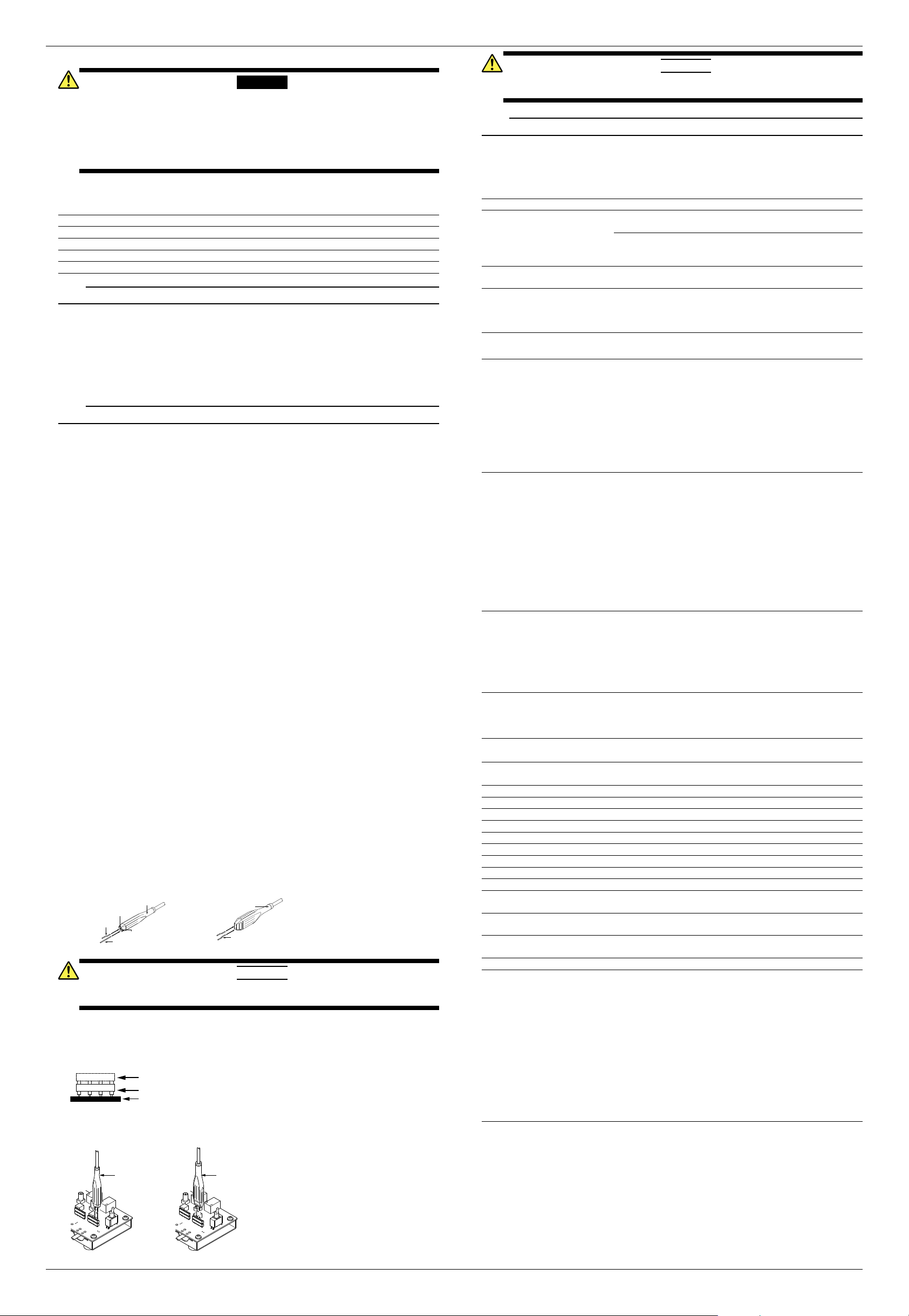
Waveform Measurement Connector
• As for the waveform measurement connectors (CN3, CN12, CN17, CN18, CN26, and CN32),
insert the accessory connectors into the connectors already installed on the test fixture in a twolayer configuration. The connectors come in two layers upon shipment.
Fixture
Waveform measurement connectors
Accessory connectors stacked
in two layers
• Affix the dedicated attachments to the PBA2500 and PBD2000 probes, then insert into the
specified pins of the second layer of connectors. For the locations and numbers of pins, see the
procedure manuals for the individual tests.
LED3
[
TEST
]
CN34
RL2
[
INIT
]
LED2
CN32
CN35
GND
[
DEVICE SQ TEST
]
CN31
CN30
CN29
RL1
CN28
CN26
E RECEIVER
IVITY TEST
1
1
CN25
G
D-
D+
G
G
D-
D+
G
D-
VBUS
LED3
[
TEST
]
CN34
RL2
[
INIT
]
LED2
CN32
CN35
GND
[
DEVICE SQ TEST
]
CN31
CN30
CN29
RL1
CN28
CN26
E RECEIVER
IVITY TEST
1
1
CN25
G
D-
D+
G
G
D-
D+
G
D-
VBUS
+
-
PBA2500
Active Probe
PBD2000
Differential Probe
CAUTION
Do not insert anything into the waveform measurement connectors other than the PBA2500
or PBD2000 with dedicated attachments affixed, or the accessory sockets.
Note
Never pull out the top layer of connectors except when changing them.
7. Troubleshooting
Troubleshooting
If servicing is necessary, or if the fixture is not operating correctly after performing the corrective
actions below, contact your nearest YOKOGAWA dealer.
Description Possible Problem Corrective Action
LED1, 2, or 3 does not turn ON. Using an AC adapter of a
voltage outside the rated range.
Use the AC adapter that came
with the fixture.
Faulty connection between the
AC adapter and the CN100
connector of the test fixture.
Check the connection between
the AC adapter and connector
CN100 of the test fixture.
Trigger does not activate on the
inrush current waveform.
SW5 not set to TEST ON. Set SW5 to TEST ON when
measuring.
The VID, PID, connected
address, and port of the DUT
(host/hub) are not displayed in
the HS Electrical Test Tool.
SW8 not set to INIT. Set SW8 to INIT.
8. Specification
Safety Standards
Conforming standards EN61010-1
Overvoltage category (installation category) II*
Pollution degree 2**
* Overvoltage category (installation category) is a number that defines excessive voltage, and
includes regulations for impulse withstand voltage. II applies to electrical equipment that is
powered by a fixed installation such as a distribution board.
** Pollution degree refers to the degree of adherence by a solid, liquid, or vapor that reduces
the withstand voltage or surface resistance factor. Pollution degree 2 applies to normal indoor
atmospheres (with non-conductive pollution) only.
Emmisions
Conforming standards EN61326-1 Class A
EN61326-2-1
EN55011 Class A, Group 1
C-tick EN55011 Class A, Group 1
This product is a Class A (for industrial environment) product. Operation of this product in a
residential area may cause radio interference in which case the user is required to correct the
interference.
Cable conditions
• Use a 5 m USB cable at CN20 (receptacle A) on the INRUSH TEST block.
• Use a 5 m USB cable at CN34 (receptacle B) on the DEVICE SQ TEST block.
• Use a 1 m USB cable at the A and B receptacles on the other TEST blocks.
Immunity
Conforming standards EN61326-1 Table 2 (for use in industrial locations)
EN61326-2-1
Cable conditions
• Use a 5 m USB cable at CN20 (receptacle A) on the INRUSH TEST block.
• Use a 5 m USB cable at CN34 (receptacle B) on the DEVICE SQ TEST block.
• Use a 1 m USB cable at the A and B receptacles on the other TEST blocks.
Reference operating
conditions
Ambient temperature 23˚C±5˚C
Ambient humidity 55 ± 10% RH
Error in supply voltage
and frequency
Within 1% of rating
Storage Environment Temperature –20˚Cto60˚C
Humidity 20% to 80% RH (no condensation)
Operating environment Temperature 5˚Cto40˚C
Humidity 20% to 80% RH (no condensation)
Storage altitude 3000 m or less
Operating altitude 2000 m or less, indoors
Rated supply voltage 100 to 240 VAC
Permitted supply voltage range 90 to 264 VAC
Rated supply frequency 50/60 Hz
Permitted supply frequency range 45 to 66 Hz
Test fixture input voltage 5 V ± 5%
Test fixture power fuse 1.1 A time lag, UL/CSA compliant
Maximum power consumption Approximately 7 VA
Withstand voltage (AC adapter, between input
terminal and output terminal)
3.0 kVAC for one minute
Insulation resistance (AC adapter, between input
terminal and output terminal)
500 VDC, 100 MΩ or more
External dimensions Approximately 317 (W) x 31 (H) x 75 (D) mm,
excluding projections
Weight Approximately 430 g, excluding AC adapter
Standard Accessories
AC adapter (A1626UP) 1
Power cord 1
Waveform Measurement Connector (B8080YH) 6
PBD2000 probe pin, B8080JP (variable type) 6
PBA2500 probe pin, B8080JP (variable type)
B8080JQ (straight type)
4
4
Carrying case (B8080JL) 1
User's manuals (this manual) 1
• Only with the /F30 option
Software (CD-ROM) 1
Software user’s manual (IM701985-61E) 1
The procedures for device, host, and hub are included in PDF format on the software CD-ROM.
IM 701985-01E 3rd Edition 2/2
 Loading...