

Page 1

GAS & STEAM
FLOW COMPUTER
MODEL 415
6 December 1999
Page 2

Page 3

CONTENTS
List of Symbols
1. Introduction 7
1.1 Model Number Designation 9
2. Specification 10
3. Operation 14
3.1 Front Panel Operation 14
3.2 Flow Equations for Gases 16
3.2.1 Ideal Gas Law 22
3.2.2 General Gas 24
3.2.3 Natural Gas 25
3.3 Steam Measurement 26
3.4 Filtering 31
3.5 Non-Linearity Correction 33
3.5.1 Digital Input Linearity Correction 33
3.5.2 Analog Input Linearity Correction 35
3.6 The Output Pulse 37
4. Options 39
4.1 The 4-20mA Output Option 39
4.1.1 Load Specification 40
4.1.2 Calculation 40
4.2 The RS232/422/485 Interface Option 43
4.2.1 Hardware 43
4.2.2 Multipoint Communication 44
4.2.3 Communication Protocol 46
4.3 Data Logging 48
4.4 The Relay Output Option 49
Page 4

5. Calibration 50
5.1 Programming Chart 52
5.2 Definitions 59
6. Input Circuits 62
6.1 Frequency Flow Input 62
6.2 Analog Inputs 67
6.3 Remote Switches (Model 415A Only) 70
7. Installation 71
7.1 General 71
7.2 Wiring Designations for the Mode 415 73
Appendix 75
Properties of Selected Gases 75
Index 77
Page 5

List of Symbols Used in this Manual
Symbol Description SI Units US Units
A Normalised signal from the
flowmeter which will be 0 at 4mA
and 1 at 20mA.
G Specific Gravity for Gas.
Specific Enthalpy at Reference
h
B
kJ/kg kJ/kg
Conditions.
Specific Enthalpy at Flow
h
F
kJ/kg kJ/kg
Conditions.
K-factor (pulses/unit) for a
K
F
pulses/m
3
frequency flowmeter.
N Timebase Constant with which the
flowrate is displayed and is:
1 for units/second
60 for units/minute
3600 for units/hour
86400 for units/day
Density at base conditions. kg/m
ρ
B
Density at flow conditions. kg/m
ρ
F
P
Pressure at base conditions. kPa (abs) psia
B
3
3
pulses/ft
lbs/ft
lbs/ft
3
3
3
Critical pressure of gas. kPa (abs) psia
P
C
Page 6

Symbol Description SI Units US Units
Pressure at flow conditions. kPa (abs) psia
P
F
Energy value of steam. MJ/day
Q
E
BTU x 1000/day
MJ/hr
MJ/min
BTU x 1000/min
MJ/sec
Mass Flowrate. kg/day
Q
M
kg/hr
kg/min
kg/sec
Volume Corrected Flowrate. m3/day
Q
VB
3
/hr
m
3
/min
m
3
/sec
m
Note: If the corrected flowrate is at standard base conditions, then the
flow will be in scm or scf (ie. standard cubic meters or feet).
If the corrected flowrate is at normalised base conditions, then the
3
flow will be in Nm
Span (Mass Flowrate at 20mA). kg/day
S
M
(ie. Normalised cubic meters).
kg/hr
kg/min
kg/sec
BTU x 1000/hr
BTU x 1000/sec
lbs/day
lbs/hr
lbs/min
lbs/sec
3
/day
ft
3
/hr
ft
3
/min
ft
3
/sec
ft
lbs/day
lbs/hr
lbs/min
lbs/sec
Span for a volumetric flowmeter (eg
S
V
vortex).
m3/day
3
/hr
m
3
/min
m
3
/sec
m
ft
ft
ft
3
ft
3
/day
3
/hr
/min
3
/sec
Page 7

Symbol Description SI Units US Units
Span (Volumetric Flowrate at
S
VB
20mA) and at base conditions.
Temperature at base conditions. °K
T
B
m3/day
3
/hr
m
3
/min
m
3
/sec
m
(Kelvin)
Critical temperature of gas. °K °R
T
C
Temperature at flow conditions. °K °R
T
F
Specific Weight of Steam at
ν
B
Reference Conditions.
Specific Weight of Steam at Flow
ν
F
Conditions.
Compressibility at base conditions.
Z
b
Z
Compressibility at flow conditions.
F
dm3/kg dm3/kg
dm3/kg dm3/kg
3
/day
ft
3
/hr
ft
3
/min
ft
3
/sec
ft
°R
(Rankin)
Page 8

Page 9

Introduction 7
1. INTRODUCTION
The Model 415 Gas Flow Computer incorporates compensation for gas and
vapours to the following equations:
1. Ideal Gas Law using temperature & pressure correction, but where
compressibility is ignored.
2. General Gases where compressibility is calculated using the
1
Redlich-Kwong
3. Natural Gas using NX-19
equation.
2
equation for supercompressibility.
4. Steam Equations for both saturated and superheated steam. Mass and
energy flowrates are calculated using standard equations to determine
the specific weight and enthalpy of steam.
Inputs from a wide range of flowmeters are handled including vortex, turbine,
orifice plate, averaging pitot tubes, wedges, V-Cones and target flowmeters. In
addition, where two differential pressure transmitters are used across an orifice
(or similar device) to increase the measured flowrange, both D.P. transmitter
inputs can be accepted into the Flow Computer and scaled separately with
automatic crossover.
Options include a 4-20mA re-transmission, high and low flow alarms and an
RS232/422/485 output. A unique feature available with the RS232/422/485
output is the ability to print flowrates and totals at programmable time intervals.
This enables the instrument to function as a data logger when used in conjunction
with a printer, or other storage device.
Two versions of the instrument are available, the Model 415R with direct RTD
input, and the 415A with a 4-20mA temperature input. Both accept a 4-20mA
pressure input.
The Model 415 is designed to supersede the Models 405GS and 405ST.
1
Redlich & Kwong. "An equation of State". Chem Rev, vol 44, p233, 1949.
2
Par Research Project NX-19. "Extension of Range of Supercompressibility
Tables", American Gas Association, 1962.
Page 10

8 Introduction
This instrument conforms to the EMC-Directive of the Council of European
Communities 89/336/EEC and the following standards:
Generic Emission Standard EN 50081-1 Residential, Commercial & Light
Industry Environment.
Generic Emission Standard EN 50081-2 Industrial Environment.
Generic Immunity Standard EN 50082-1 Residential, Commercial & Light
Industry Environment.
Generic Immunity Standard EN 50082-2 Industrial Environment.
In order to comply with these standards, the wiring instructions in Section 7.1
must be followed.
Page 11

Introduction 9
1.1 MODEL NUMBER DESIGNATION
The Model number of an instrument describes which input and output options are
installed and the AC mains voltage rating.
Model 415 R. 1 0 E C
C for Conformal Coating
E for 220/240 VAC
A for 110/120 VAC
D for DC Power Only
Temperature Options
R for RTD input 0 for no option
A for 4-20mA 1 for 4-20mA output
2 for RS232/422/485
3 for Relay option
4 for 4-20mA and relays
5 for RS232/422/485 and relays
Mounting
1 for panel mounting
2 for field mounting
3 for explosionproof
The Model number of the instrument is displayed on first entering the
Calibration Mode (see Section 5).
Page 12

10 Specification
2. SPECIFICATION
General
Display: Alphanumeric LCD display with
backlighting and 2 lines x 20 characters/line.
Each character 5.5mm high.
Keyboard: Sealed membrane keyboard with four keys.
Transducer Supply: 8-24VDC field adjustable, 65mA maximum.
Power Requirements: 14 to 28.0 VDC, 300mA typical.
AC mains - Set internally to 95 - 135 VAC
or 190 - 260 VAC.
Operating Temperature: 0 to 55°C.
Facia: Watertight to IP65 or Nema 3S.
Dimensions: 144mm (5.7") wide x 72mm (2.8") high x
188mm (7.4") deep.
Depth behind Panel: 139mm (5.5") x 67mm (2.6").
Frequency Input
Frequency Range: Minimum: 0.25Hz on Rate.
0Hz on Total.
Maximum: 10KHz.
Input Circuits: Will accept most sine logic and proximity
switch inputs (see section 6.1).
K-factor Range: 0.1000 to 999,999.
Non-Linear Correction: Up to 10 correction points.
Page 13

Specification 11
4-20mA Inputs
Inputs: Flow (2), pressure & temperature.
Input Impedance: 250 ohms.
Measurement Ranges: Pressure: 0kPa (abs) (0 psia) to 100,000 kPa
(10,000 psia).
Temp:-273°C (-459.4°F) to 1200°C (2192°F).
Accuracy: 0.05%
Circuit: The 250 ohm resistors are connected to a
common signal ground (current sinking).
Span (Flow): 999,999.
RTD Input (Model 415R)
Temperature
Measurement Range: -100°C (-148°F) to 200°C (392°F),
Note: a wider temperature range can be
handled via a 4-20mA input.
Accuracy: 0.1°C
RTD Type: Platinum PT100.
Linearity: The non-linearity of the RTD is internally
compensated for.
Pressure Input
Type: Absolute or Gauge.
Span: The absolute or gauge pressure at both 4mA
and 20mA is programmable.
Atmospheric: If a gauge pressure sensor is used the
atmospheric pressure can be programmed.
4-20mA Output
Function: The flowrate selected as the Default display
is output on the 4-20mA output.
Resolution: 10 bits.
Accuracy: Better than 0.1%.
Maximum Load: 500 ohms internally powered.
950 ohms from 24 VDC.
Isolation: Output is isolated.
Page 14

12 Specification
Relay Output
Function: High and low flowrate alarms based on the
flowrate selected as the default display.
Maximum Switching Power: 1250VA.
Maximum Switching Voltage: 250 VAC, 30VDC.
Maximum Switching Current: 5 Amps.
RS232/422/485 Option
Type: Both RS232 & RS422/485 are provided.
Function: Printer and computer protocols are
programmable.
Output: Output is on request or at a programmable
time interval.
Baudrate: 300 to 9600.
Data Bits: 7 or 8.
Parity: None, Odd, Even.
Pulse Output
Function: The pulse output is scaled and outputs one
pulse each time the Default total increments
by one digit.
Pulse Width: 10mSec (negative going pulse).
Duty Cycle: Maximum of 49 pulses per second.
Output: An open collector transistor will sink 100mA
maximum.
Ideal Gas
3
Display: Corrected Volume (m
or ft3).
Mass (kg or lbs).
Temperature Range: -273°C (-450°F) to 800°C (1472°F).
(RTD has a more limited range.)
Pressure Range: 0 kPa abs (0 psia) to 100,000 kPa (10,000
psia).
Page 15

Specification 13
General Gas
Gases: Handles most gases for which the critical
temperature, pressure and SG are known.
Compressibility: Calculated using Redlich-Kwong equation.
3
Display: Corrected Volume (m
or ft3).
Mass (kg or lbs).
Temperature Range: -273°C (-450°F) to 800°C (1472°F).
(RTD has a more limited range.)
Pressure Range: 0 kPa abs (0 psia) to 100,000 kPa (10,000
psia).
Natural Gas
Calculations: Uses NX-19 equation to calculate
supercompressibility Fpv.
3
Displays: Corrected Volume (m
or ft3).
Mass (kg or lbs).
Temperature Range: -40°C (-40°F) to 115°C (240°F).
Pressure Range: 101.325 kPa (14.69 psia) to 34,380 kPa (4985
psia).
SG Range: 0.554 to 1.000.
Carbon Dioxide: 0 to 15% mole.
Nitrogen: 0 to 15% mole.
Steam
Displays; Mass (kg or lbs)
Energy (MJ or BTU x 1000).
Calculations: Uses 1967 IFC Formulation equations to
calculate specific weight and enthalpy of
steam.
Steam Type: Saturated and Superheated.
Temperature Range: 20°C (68°F) to 800°C (1472°F).
(RTD has a more limited range.)
Pressure Range: 1 kPa (abs) (1 psia) to 100,000 kPa (10,000
psia).
Page 16

14 Operation
3. OPERATION
The Model 415 uses a low power CMOS microprocessor to perform all
measurement and control functions.
The instrument is fully programmable with all operating parameters and
calculation constants user programmable (see Section 5 entitled Calibration for
information on programming). All parameters and constants are stored in a
non-volatile memory which retains data without battery backup for a minimum of
10 years.
3.1 FRONT PANEL OPERATION
The alphanumeric display provides a clear indication of which parameter is
displayed and the engineering units.
During Calibration, the value which is to be normally displayed can be
programmed as the DEFAULT display. For example, if Mass is required and is
programmed as the DEFAULT display, then pressing the RATE key will show
the Mass flowrate, and pressing the TOTAL key will show the Mass total.
The scaled pulse out, 4-20mA output option and high/low alarm option are also
based on the DEFAULT display selection. For example, the 4-20mA output
would be a re-transmission of the Mass flowrate, if the DEFAULT display is set
to Mass.
The DISPLAY key can be used to step through the data which can be displayed,
as follows:
Gas Flow
Corrected Volume (Rate & Total)
Mass (Rate & Total)
Temperature & Pressure
Page 17

Operation 15
Steam
Mass (Rate & Total)
Energy (Rate & Total)
Temperature & Pressure
Specific Weight & Enthalpy
If any value other than the default display values are selected, they will remain
displayed for 5 seconds, after which the display will automatically revert to the
default values.
Totals are displayed with a maximum of 8 digits, including decimals. For
example, if two decimals are programmed, the maximum total is 999,999.99,
after which the totals roll over to zero and continue counting.
For large flowrates, totals can be integrated at 1/1000 of the flowrate by
programming the Total Units function at x 1000. The units of measure will then
be displayed as follows:
SI Units
Rate Total
cm/h kcm
scm/h kscm
Nm
3
kNm
3
kg/h tonne
MJ/h GJ
US Units
Rate Total
cft/h kcft
scft/h kscft
lbs/h klbs
BTU x 1000/h MBTU
(Note: k = x 1000, M = x 1,000,000, G = x 1,000,000,000).
The RESET key can be used to reset the totals whenever one of the totals is
displayed. Both totals will be reset at the same time. The RESET switch can be
disabled during calibration to prevent front panel resetting.
Page 18

16 Operation
3.2 FLOW EQUATIONS FOR GASES
This section applies only to gas flow measurement and, if the Model 415 is to be
used for steam measurement, the reader can skip this section and go to section
3.3.
The Model 415 will accept inputs from a wide range of flowmeters with the
flowrate calculated by the equations defined below. Both mass flow and volume
corrected flow to a base temperature and pressure are calculated and displayed in
either SI (metric) or US units. For an explanation of the symbols used in the
equations see the list at the beginning of this manual.
Two basic formulae are common to all equations:
1. Specific Gravity, G =
2. Density of a Gas,
MolecularWeight ofGas
MolecularWeight ofAir
MolecularWeight ofGas
.....(1)=
ρ
at base conditions:
,
In SI Units
3.4834 G P
=
ρ
kg/m
B
In US Units
2.6988 G P
=
ρ
B
ZBT
Standard Conditions
Standard conditions are defined as:
15°C (288.15°K) and 101.325 kPa
or 59°F (518.67°R) and 14.69595 psia.
ZBT
28.9625
B
B
B
B
lbs/ft
3
3
.....(2)
.....(3)
Page 19

Normalised Conditions (SI Units only)
A
Normalised conditions are defined as:
0°C (273.15°K) and 101.325 kPa.
A. Volumetric Flowmeters With Frequency Output.
eg. Vortex, turbine or positive displacement flowmeters.
Operation 17
VB
=
N. frequency(Hz)
K
F
VB
P
T
F
.
P
B
Z
B
B
.
.
T
Z
F
F
......(4)Q
......(5)QM= ρB.Q
B. Volumetric Flowmeters With 4-20mA Output.
eg. Vortex, turbine or positive displacement flowmeters with frequency to
current convertors.
P
T
Q
VB=SV
.
QM= ρB.Q
F
P
B
VB
Z
B
B
.
.
T
.
Z
F
F
......(6)
C. Differential Pressure Flowmeters With 4-20mA Output And A Square
Law Relationship.
eg. Orifice Plates, Averaging Pitot Tubes, Target Flowmeters, etc.
P
T
VB=SVB
QM= ρB.Q
F
.
.
P
B
VB
Z
B
B
.
Z
F
.A
T
F
......(7) Q
Page 20

A
18 Operation
D. Differential Pressure Flowmeters With 4-20mA Output And With A
Linear Flow Relationship.
eg. D.P. transmitters with a square root extractor or VA meters.
P
T
VB=SVB
F
.
.
P
B
Z
B
B
.
T
F
.
Z
F
......(8)Q
QM= ρB.Q
VB
Note that the pressure and temperature are still square rooted, even though
the flow signal A is not. This is because the output from the D. P.
transmitter is not truly volumetric, but will be affected by a change in
density of the gas being measured. Therefore, the equations relating to
differential pressure will apply.
E. Dual Differential Pressure Flowmeters With 4-20mA Output.
To increase the range over which flow can be measured, two D. P.
transmitters with different spans can be connected across a common
orifice or other differential pressure device.
Equations 5 & 6 or 7 & 8 above would be used depending upon whether
the D. P. transmitters have square root extractors. Separate scaling using
these equations is then programmed for each transmitter.
At lower flowrates, transmitter 2 will be used as a basis of measurement
and at higher flowrates, transmitter 1 will be used. The crossover point
will occur when the input on transmitter 2 exceeds 20mA.
Page 21

Operation 19
Example 1
Flow is to be measured across an orifice in the range of 0 - 2000
scm/hr. Because flow needs to be measured over a 10:1 range, two
transmitters are spanned as follows:
Transmitter 2 0 - 600 scm/hr
Transmitter 1 0 - 2000 scm/hr
Hence, above 600 scm/hr, transmitter 2 is used and below 600
scm/hr, transmitter 1 is used. Since D. P. transmitters are accurate
over a 3:1 range, then the system will provide reliable readings
between 200 to 2000 scm/hr, which is a 10:1 turndown.
Both transmitters will be individually scaled to equations 5 & 6 or
7 & 8, as appropriate.
PROGRAMMING THE FLOW COMPUTER
For equations 4 to 8 to work correctly, a number of parameters need to
be programmed:
K-factor (for frequency producing flowmeters)
K
F
(or SM) Span (for analog flowmeters)
S
VB
T
B
P
B
Base temperature
Base pressure
G Specific Gravity of Gas
The flow computer will measure the flow input A (normalised between
0 and 1), the temperature, T
, and pressure, PB. Depending on the gas
F
equation selected, the compressibility factors and density are then
calculated. Other parameters must also be programmed and these are
fully detailed in section 5.
Page 22

ρ
20 Operation
PROGRAMMING THE SPAN AS MASS
It is also possible to enter the span of an analog flowmeter in mass
(instead of volume) at a nominal flowrate. The flow computer will
then automatically calculate the Span, S
as:
=
S
VB
Example 2
If a flowmeter produces 1000 kg/h at 30°C and 220 kPa, and the
specific gravity is 1.52 then from equation (2)
3.4834 x 1.52 x 220
ρ =
1x(30 + 273.2
, for corrected volume flow
VB
S
M
B
)
......(9)
(assuming ZB = 1)
= 3.84 kg/m
3
Therefore, from equation (9)
1000
=
S
VB
3.84
= 260 m
3
/hr
If the span is programmed as mass SM = 1000 kg/hr, with the base
temperature programmed to 30°C and the base pressure
programmed to 220 kPa, then the flow computer will display both
mass (kg/hr) and volume (m
3
/hr) corrected to a base condition of
30°C and 220 kPa.
Page 23

and
Operation 21
Example 3
If the mass flow is defined at non- standard base conditions and it
is required to display the corrected volume at standard conditions,
then it is first necessary to convert the mass to an equivalent mass
at standard conditions.
Using example 2 for a differential pressure device, the
corresponding mass at 15°C and 101.325 kPa can be determined
from equation 7 as:
P
T
S
M1=SMB
1
.
.
P
B
Z
B
B
.
T
Z
1
1
where SM1 = the new span at 15°C and 101.325 kPa
with the input A = 1
Therefore, the new span S
= 1000 x
S
M1
, with ZB = Z1= 1, is:
M1
101.325
220
x
30 + 273.2
15 + 273.2
= 696.1 kg/hr
Hence, the span would be programmed as 696.1 kg/hr, the base
temperature as 15°C and the base pressure as 101.325 kPa. The
corrected volume will now be displayed at standard conditions.
Page 24

22 Operation
3.2.1 Ideal Gas Law
If the effects of compressibility on a gas can be ignored, then Z
and ZF can be set
B
to 1.00 in equations 1 to 8. This can make calculations much simpler,
particularly when the properties of a gas are not known or, over small ranges of
pressure and temperature, where the effects of compressibility are often
negligible.
Example 4
A vortex meter is used to measure oxygen in a 2" pipe at 25° C and
200 kPa (abs). The flowmeter produces 9500 pulses/m
flowrange is 100 to 1000 m
3
/h. Determine the flow parameters
3
and the
which need to be programmed into the instrument for it to display
the flowrate and total flow as both mass and corrected volume to
Standard Conditions.
From the table, the Molecular Weight of oxygen is 31.9988. From
equation (1)
31.9988
28.9625
= 1.105
G=
According to ISO5024, Standard Conditions are 15° C (59° F) and
101.325 kPa (14.69595 psia). Hence, the following are
programmed into the instrument:
Scaling Factor (K-factor) = 9500 pulse/m
3
Specific Gravity G = 1.105
Base Temperature = 15 °C
Base Pressure = 101.325 kPa
Timebase of Rate = Hours
Other parameters can be programmed as required.
The instrument will now display the corrected volume and mass
flowrates of the gas.
Page 25

Example 5
Operation 23
The same vortex meter installation, as detailed in Example 4, also
has a 4-20mA output. The meter produces 20mA at 1000 m
4mA at 0 m
3
/h. Determine the flow parameters which need to be
3
/h and
programmed for mass flow and corrected volume to standard
conditions.
With the instrument set for a linear 4-20mA input signal, the
following parameters are programmed:
Span (S
) = 1000 m3/h
V
Specific Gravity G = 1.105
Base Temperature = 15 °C
Base Pressure = 101.325 kPa
Timebase of Rate = Hours
Page 26

24 Operation
3.2.2 General Gas
For general gases, the compressibility is calculated using the Redlich-Kwong
equation. In order to calculate the compressibility of a gas, it is necessary to
know the critical temperature and pressure. From these parameters, the
compressibility factors Z
and ZF are calculated for a gas.
B
A list of common gases with specific gravity and critical temperatures &
pressures is given in the appendix to this manual.
The equations 1 to 9 are then used to calculate both corrected volume and mass
flow.
Example 6
It is required to measure Hydrogen via an orifice plate using
compressibility. Find the critical temperature and pressure which
need to be programmed and the specific weight.
From the table, in the appendix,
= -239.9 C
T
C
= 1296.9 kPa
P
c
G = 0.0696
Page 27

3.2.3 Natural Gas
Operation 25
In the gas industry, compressibility is referred to by a factor, F
, termed the
PV
supercompressibility factor where:
Z
B
=
PV
Z
F
FPV is calculated in the flow computer using the NX-19 equation for natural gas
and (F
In order to calculate F
2
)
is substituted into equations 4 to 8 in place of .
PV
, the following must be programmed within the following
PV
Z
B
Z
F
......(10)F
ranges:
Specific Gravity G: 0.554 to 1.000
Carbon Dioxide mol%: 0 to 15%
Nitrogen mol%: 0 to 15%
Also, the temperature and pressure must be within the following ranges:
Temperature -40 to 115°C
(-40 to 240°F)
Pressure 0 to 34,372 kPa
(0 to 5000 psia)
Page 28

26 Operation
3.3 STEAM MEASUREMENT
The Model 415 incorporates equations to handle both saturated and superheated
steam over the following range:
Pressure 0 kPa abs (0 psia) to 100,000 kPa abs (10,000 psia)
Temperature 100°C (212°F) to 800°C (1472°F).
When measuring saturated steam, it is possible to delete either the pressure or
temperature sensor since, on the saturation line, there is a corresponding pressure
for all temperatures. For superheated steam, it is necessary to use both the
pressure and temperature sensors.
Both the mass flow (in kg/hr or lbs/hr) and the heat content (enthalpy) are
calculated internally based on the 1967 IFC Formulation (ASME) Equations.
The equations use the pressure and temperature readings to determine:
ν
, the specific volume of steam in dm3/kg or,
-
- h, the specific enthalpy of steam in kJ/kg.
A. Volumetric Flowmeters With Frequency Output.
eg. Vortex, Steam turbines, etc.
Mass Flow
US Units : Q
M(SI)
M(US)
=1000.
= 62.435 .
N. frequency (Hz)
K
F
N. frequency
K
1
.
ν
F
1
.
ν
F
F
(Note: for US units KF is in pulses/ft3.)
......(11)SI Units : Q
......(12)
Page 29

Energy Flow
A
Q
xh
M(SI)
=
E(SI)
E(US)
1000
= 0.42992
Q
M(US)
1000
xh
B. Volumetric Flowmeters With 4-20mA Output.
eg. Vortex or Steam turbines with frequency to current convertors.
Mass Flow
S
V
x
ν
F
S
V
xA
ν
F
US Units : Q
M(SI)
M(US)
= 1000 x
= 62.447 x
Energy Flow
Operation 27
......(13)SI Units : Q
......(14)US Units : Q
......(15)SI Units : Q
......(16)
Equations 13 & 14 are used.
C. Differential Pressure Flowmeters With 4-20mA Output And A Square
Law Relationship.
eg. Orifice Plates, Averaging Pitot tubes, target flowmeters, etc.
Mass Flow
M=SM
ν
F
.A
......(17)Q
ν
B
.
Energy Flow
Equations 13 & 14 are used.
Page 30

A
28 Operation
D. Differential Pressure Flowmeters With 4-20mA Output And With A
Linear Flow Relationship.
eg. D. P. transmitters with a square root extractor or VA meters.
Mass Flow
ν
B
.
Q
M=SM
.
ν
F
......(18)
Energy Flow
Equations 13 & 14 are used.
Note that the Specific Weight (density) is still square rooted even though
the flow signal A is not. This is because the output from the D. P.
transmitter is not truly volumetric, but will be affected by a change in the
steam density. Therefore, the gas equations relating to differential
pressure must apply.
E. Dual Differential Pressure Flowmeters With 4-20mA Output.
To increase the range over which flow can be measured, two D. P.
transmitters with different spans can be connected across a common
orifice or other differential pressure flowmeter.
Equations 17 or 18 would be used depending on whether the D. P.
transmitters have square root extractors. Separate spans are then
programmed for each transmitter and at lower flowrates transmitter 2 will
be used. At higher flowrates, where the output of transmitter 2 exceeds
20mA, transmitter 1 will be used.
Page 31

Operation 29
PROGRAMMING THE FLOW COMPUTER
For equations 11 to 18 to work, a number of parameters need to be
programmed. These include:
K
S
M
ν
K-factor (for frequency producing flowmeters).
F
Span (for analog flowmeters).
Base specific weight at which the span is determined.
B
The flowmeter will measure the flow input A (normalised between 0
and 1) and the temperature T
pressure are used to calculate the specific weight,
and pressure PF. The temperature and
F
ν
, and enthalpy, h,
from internal equations. Other parameters must also be programmed
and these are fully detailed in section 5.
Example 7
A vortex flowmeter has a K-factor of 68.32 pulses/ft
3
, and it is
required to measure saturated steam in lbs/hour. What are the
main parameters to be programmed?
The instrument should be programmed for steam measurement
from a frequency meter. Because the steam is saturated, it is only
necessary to use either a temperature or pressure sensor. Because
of cost, a temperature probe is used. The main parameters to
program are simply:
Units US Units
K-factor = 68.32
Timebase hours
Page 32

30 Operation
Example 8
A differential pressure transmitter across an orifice is designed to
output 20mA at 10,000 kgs/hour at a reference pressure of 1300
kPa (abs) and specific weight of 216.05 dm
required in kg/hour and the calorific value in MJ/hour. What are
the main parameters to be programmed?
3
/kg. The flowrate is
From the steam tables at 1300 kPa (abs) and a specific weight of
216.05 dm
3
/kg, the temperature can be calculated as 350°C, and is
in a superheated state. Hence, steam measurement via a 4-20mA
input with square law relationship is selected and the following key
parameters are programmed:
Units SI Units
Span 10,000
Base Temperature 350°C
Base Pressure 1300 kPa
Timebase hours
Steam Superheated
Page 33

Operation 31
3.4 FILTERING
Frequency fluctuations caused by pulsating flow through a flowmeter, often make
the Rate impossible to read with any precision.
The Flow Computer `as a digital filter which will average out these fluctuations
and enable the Rate to be read to four digit accuracy. The ability to select a
suitable filtering level means that highly accurate and stable readings can be
obtained without excessive lag. When the Rate is retransmitted via the 4-20mA
output, the filtering will also average out any fluctuations on the output.
The diagram below shows a pulsating signal input together with the effect of
filtering.
Rate
Filtered Response
Unfiltered Response
Time
As a guideline to the degree of filtering to be used, the following table shows the
response to a step change in input. The value, A, is the filter constant which is
programmed during the Calibration routine. The times for the display value to
reach 90% and 99% of full swing are given in seconds, for different values of A.
Page 34

32 Operation
A 90% 99%
100
212
424
636
10 5 11
15 8 17
20 11 22
25 14 28
35 20 40
45 25 51
60 34 69
75 43 86
90 52 103
99 57 113
Table 1 - Response to a step Input (in seconds).
Note that if A is set to 1 there is no filtering of the input signal.
Page 35

Operation 33
3.5 NON-LINEARITY CORRECTION
3.5.1 Digital Input Linearity Correction
Non-linearity correction enables the instrument to correct for known
non-linearities if the flowmeter. This feature is not selectable for analog flow
inputs.
Up to 10 frequencies and scaling factors can be programmed. Data on the
flowmeter non-linearity can usually be supplied by the flowmeter manufacturer in
the form of a Calibration Certificate, and is the result of individual tests on a
flowmeter over a range of flowrates. The Certificate will list a number of
flowrates or frequencies with the measured K-factor (eg. pulses per gallon or
litre) at each flowrate.
The following diagram graphs the change in scaling factor with frequency for a
hypothetical flowmeter. The heavy black line represents the actual scaling factor
of the flowmeter, while the light black line is the approximation used in the
instrument.
Scaling Factor
Fact 4
Fact 6
Freq
6
Fact 5
Freq
5
Freq
4
Freq
3
Fac t 3
Fact 2
Freq
2
Freq
1
Fact 1
Frequency
Max
Frequency
Linear Interpolation is used between points on the curve, except for Factor 1
which maintains a constant value between Frequency 1 and the maximum input
frequency.
Page 36

34 Operation
During Calibration, the program requires the user to input a frequency and the
Scaling Factor (K-factor of the flowmeter) at up to 10 points on the curve.
Generally these points will correspond to those shown on the Certificate.
If any frequency is set to 0Hz (Frequency 6 in the preceding example), then the
program will require no further correction points to be programmed. Hence, the
user can program any number of correction points up to a maximum of 10. Note
that if all 10 correction points are required, then Frequency 10 will automatically
be assigned the value of 0Hz.
Page 37

Operation 35
3.5.2 Analog Input Linearity Correction
For single analog flow inputs, an input table can be programmed to correct for
any non-linearities between the flow signal and the actual flowrate. This feature
is very useful when using the flow computer with some types of VA flowmeters
or laminar flow tubes which may exhibit slight non-linear characteristics.
Up to 20 points can be programmed, and linear interpolation is then used
between points in the curve. The table works by inputting a normalised flow
input signal A, into the table and produces a corrected output A
ranges between 0 and 1.0000 so that, at a 4mA input, both A and A
. The table
C
equal 0 and
C
at 20mA both values must also equal 1.0000.
The user programs the table starting with 1.0000 and programs corresponding
values of A and A
. As soon as A is programmed as 0.0000, no further input to
C
the table is possible and the program will correct over the number points that
were programmed. A maximum of 20 points can be programmed.
At the base temperature and pressure, the flow equation, with non-linearity
correction is defined as:
Q=Span.A
C
Note: The square root relationship for conventional differential pressure
flow devices is handled separately and not by the linearity
correction described in this section.
Page 38

36 Operation
Example
A flowmeter has been tested and the following relationship between
the input and the flowrate has been determined at the nominal
temperature & pressure as follows:
Input Flowrate Normalised Inputs for
table
IncheswgD.P. OutputmAlbs/hr Input (A)
Output (A
)
C
52.2007 20.000 7075.89 1.0000 1.0000
39.3894 5306.92 0.7546 0.7500
33.3231 4422.43 0.6384 0.6250
26.7444 3537.94 0.5123 0.5000
20.1656 2653.45 0.3863 0.3750
12.9913 1768.97 0.2489 0.2500
5.5400 884.48 0.1061 0.1250
1.0388 269.06 0.0199 0.0380
0.0000 4.0000 0 0.0000 0.0000
where A =
AC=
Inches wg
Inches wg at 20mA
flowrate
flowrate at 20mA
Inches wg
=
flowrate
=
7075.85
52.2007
The values of A and AC are input into the table during Calibration
and the span would be programmed as 7075.89 such that
Q = 7075.89 x A
C
Page 39

Operation 37
3.6 THE OUTPUT PULSE
An OUTPUT PULSE is available on terminal 10 for driving remote counters
and produces a pulse each time the Total of the Default display increments by
one digit. For example, if the Default Total has a resolution of 0.01 kilograms, a
pulse is produced each 0.01 kilograms.
The pulse is a current sinking pulse of approximately 10mSec produced by an
open collector transistor and can sink up to 100mA. The maximum pulse rate is
limited to 49 pulses per second and the resolution on the accumulated total must
be set so that the accumulated total increments at less than 49 counts per second.
Note that due to the uneven pulse output spacing on this output, the pulse output
cannot be used to drive rate indicators.
Page 40

38 Operation
Connection of Output Pulse is as follows:
Model 415
5.6 ohms
33V
Zener
Relay or
Impulse Counter
10
12
DC Supply
Driving an External Relay or Impulse Counter
Model 415
DC Supply
Out (8-24V)
5.6 ohms
33V
Zener
11
External Load
Resistor 10K
10
2
Driving a Logic Input such as a PLC or Electronic Counter
Logic Input
Page 41

Options 39
4. OPTIONS
4.1 THE 4-20mA OUTPUT OPTION
The 4-20mA output option provides an analog output of the Default flowrate as
either a 4-20mA current or a 0-10 Volt level. The output will be the corrected
volume, mass or energy, depending on which parameter is programmed as the
default displayed. All output signals are electrically isolated from the instrument
power supply and signal inputs to ensure minimum interference.
Either 2 wire current transmission is available with the loop powered internally,
or 3 wire transmission from an external loop supply.
A block diagram of the output is shown below and various methods of
interconnection are outlined on the following pages.
DC to DC
Convertor
Digital to
Analog
Convertor
Opto-Isolation Amplifiers
+15V
0-10V Out
0V
-12V
Terminal
26
25
24
22
21
23
Page 42

40 Options
4.1.1 Load Specification
Maximum load which the output can drive:
Internally powered loop: 500 ohms
Externally powered: R = (V-5)/.02
where V is the external loop voltage
R is the maximum load in ohms.
Output impedance of 0-10 Volt source: 100 ohms
4.1.2 Calculation
Parameters relating to this option are programmed when calibrating the
instrument (see section 5) and provide for:
Defining the rate which is equivalent to 4mA or 0 volts.
Defining the rate which is equivalent to 20mA or 10 volts.
Selecting the output range as 4-20mA (which also gives 2-10 volts on
the voltage output circuit) or as 0-10 volts (which gives 0-20mA on the
current output circuit).
By being independently able to set the output range, the instrument can
effectively be programmed to amplify the input signal. In driving chart
recorders, for example, this enables the output to zoom in on a particular
operating area, instead of having to display the full operating range of the
transducer.
For example, 4mA may be set as 0 kg/min and 20mA as 200 kg/min. However,
the user could set 4mA as representing 100 kg/min and 20mA as representing
120 litres/min.
For rates or displayed values above and below the maximum and minimum
values the output will remain at its 20mA or 4mA level respectively.
It should be noted that the output will be updated every 0.5 seconds in unison
with the display and, between updates, the output value is constant.
Page 43

Amplifiers
Amplifiers
Terminal
+15V
0-10V Out
0V
-12V
26
25
I(+)
I(-)
24
22
21
23
Voltage Output Configurations
Terminal
+15V
0-10 V Out
I(+)
I(-)
26
25
24
22
21
Link
23
Link
LOAD
LOAD
500 ohm
maximum
Options 41
Two Wire Transmission (Internal Supply)
Page 44

42 Options
+15V
I(+)
I(-)
Terminal
26
25
24
Amplifiers
0-10 V Out
0V
-12V
22
21
23
LOAD
Three Wire Transmission (External Supply)
Page 45

Options 43
4.2 THE RS232/422/485 INTERFACE OPTION
With this option installed, the circuits for both the RS232 and RS422/485 are
provided as standard. They can be used to interface to both printers and
computers, and a number of standard protocols are built into the instrument.
4.2.1 Hardware
The following diagram provides an overview of the RS232/RS422/RS485
communications hardware. All three interfaces are available on the rear terminal
strips and the user can select either one by making the appropriate connections.
The RS232 interface is primarily used with printers or for simple communication
with a computer over a short distance. The RS422 and RS485 interfaces are used
for communication over a long distance or in applications requiring multipoint
communication.
(+)
24
23
RS422 Out
(-)
(+)
26
(-)
25
Data In
21
Data Out
22
27 CTS
20
Ground
RS422 I n
RS232
Page 46
44 Options
4.2.2 Multipoint Communication
Multipoint Communication is a system whereby a number of instruments can be
addressed over a dual twisted pair interface. Up to 32 instruments can be
connected to a common bus using the RS422 and RS485 interfaces as shown
below.
To covert the RS422 interface to an RS485 interface, the RS422 (-) Data In
Terminal must be connected to the RS422 (-) Data Out Terminal and the RS422
(+) Data In Terminal must be connected to the RS422 (+) Data Out Terminal.
These connections will convert the RS422 4 wire interface to the RS485 2 wire
interface, as shown in figure 2.
Each instrument can be programmed with a unique address which is used by the
Master Controller (ie IBM/PC) to identify each instrument. The Controller will
send the address down the line and will alert the relevant instrument.
Subsequent software protocol will control the flow of data between the Controller
and the Instrument.
Host
Compu ter
Load
120 ohms
400 Series
Instrument
Twisted Pair
Figure 1 RS422 Interface
Load
120 ohms
400 Series
Instrument
Page 47

Twisted Pair
Options 45
Host
Compu ter
Gnd
+
Load
120 ohms
-
+-
-
Gnd
In
400 Series
Instrument
Out
+
-
+--+
Gnd
In
Out
400 Series
Instrument
Figure 2 RS485 Interface
Page 48

46 Options
4.2.3 Communication Protocol
The Model 415 has a real time clock and enables the time and date to be set and
printed on tickets. The date format can be European (days/months/years) or USA
(months/days/hours), while the time is on a 24 hour clock.
Note that the clock will only retain its time for 3 days minimum if there is no
power connected to the instrument. After this period, the clock may need to be
reset.
The baudrate, parity and wordlength can be programmed during calibration and
the user must ensure that these correspond to the setting on the printer or
computer with which the Model 415 is communicating.
The software protocols can be selected during Calibration to provide standard
interfaces to a number of printers and computers. Since other interfaces will
continue to be added, the user should consult the manual "The RS232/422/485
Communications Option for the 400 Series, Version 2", for the latest protocols
and printer drivers.
Printer
A ticket is printed each time the RESET key is pressed or at defined time
intervals (see Data Logging). If the Reset key is used, the instrument prints the
ticket before resetting the totals.
Protocols are provided to drive the following printers:
1 Standard Computer Printer (Note that the printer must have an
RS232 Serial Interface).
2 EPSON CTM290 Slip Printer.
3 Contrec Model 624.
4 EPSON TM290-2 Slip Printer.
5 Contrec Model 632-2 Printer.
6 Syntest SP-210 Printer.
Page 49

Options 47
A CTS input is provided, and will prevent the instrument from transmitting any
further characters to a printer if the printer buffer is full. The CTS input is
usually connected to the "Data Buffer Full" output from the printer.
If the printer buffer is large enough to handle the messages output from the
instrument, then this input need not be used and should be left unconnected.
Computer
The instrument receives and transmits messages in ASCII, with all command
strings to the instrument terminated by a carriage return. While replies from the
instrument are terminated with a carriage return and a line feed.
Xon/Xoff protocol is also supported, and the instrument will automatically
determine if the message sent by the host computer is preceded by an Xoff
character. If it does recognise an Xoff as the first character of a command string,
the instrument will automatically switch to Xoff/Xon protocol, and begin & end
all messages with Xoff and Xon characters respectively. Xoff/Xon protocol is
only available when the RS232 interface is selected.
During Calibration, the instrument can be programmed to operate in a full
duplex or half duplex transmission mode. In full duplex mode, all commands
sent to the instrument will be echoed back to the host computer. In half duplex,
the commands are not echoed.
For more information on the computer interface please consult the manual "The
RS232/422/485 Communications Option for the 400 Series, Version 2".
Page 50

48 Options
4.3 DATA LOGGING
The Model 415 can be programmed to output data to a printer, computer or other
storage device at the following intervals:
1 minute (Every minute on the minute)
10 minutes (On the hour, at 10 past...etc)
30 minutes (On the hour and half hour)
1 hour (On the hour)
6 hours (At 6:00, 12:00, 18:00 and 24:00)
12 hours (At 12:00 and 24:00)
24 hours (At 24:00)
The totals can be programmed to reset manually via the front panel, or
automatically after each print is initiated, or at 24:00 after the print is initiated.
Note that if manual reset is selected, it is still possible to prevent front panel reset
by inhibiting this function in General Setup (in Calibration).
Page 51

Options 49
4.4 THE RELAY OUTPUT OPTION
The Relay output option consists of two Form C relays which can be preset
during calibration to energise when the Default flowrate exceeds or drops below
the preset values.
The "low" relay is energised whenever the rate is below the preset value, and the
"high" relay is energised whenever the rate exceeds the preset value. The preset
values are programmed during calibration as described in section 5.
Normally Open
34
Relay 1
Low Alarm
Relay 2
High Alarm
35
Normally Closed
36
Common
Normally Open
31
Normally Closed
32
Common
33
Page 52

50 Calibration
5. CALIBRATION
The Calibration routine enables the Setup Parameters to be programmed, as well
as enabling the input signals to be checked.
The calibration routine can be entered in two ways:
1 By connecting a wire link (or switch) to the rear terminal strip
across terminals 1 and 2 or,
2 By pressing the TOTAL key and, while still holding, pressing the
DISPLAY key. Both keys must then be held for approximately 6
seconds. This second method of access can be disabled during the
calibration so that it is only possible to enter the calibration routine
via the link across terminals 1 and 2.
The key switch actions during Calibration are as follows:
RATE will change a flashing digit, to the next digit.
TOTAL will increment a flashing digit or change a
parameter selection.
RESET will reset a flashing digit to zero.
DISPLAY (Program) will step through the program sequences.
Note that the arrows in the Rate and Total key switches indicate that these
switches can be used to change and increment digits respectively.
In stepping through the program sequence, the Parameter Description is always
shown. When a value or parameter can be changed, it is always shown as
flashing, and the LED's in the switch panels are lit if that key switch can be used
to change a value.
Page 53

Calibration 51
On first entering the Calibration routine, the display will show the Model number
followed by:
SELECT
(GENERAL SETUP)
There are six main menu items as follows:
1. GENERAL SETUP
2. GAS PARAMETERS
3. FLOW PARAMETERS
4. OPTIONS
5. TEST
6. EXIT
The user can toggle between these menus using the " " key. To enter a menu,
the DISPLAY key is then pressed.
In the following flowcharts, the options which can be selected using the or
keys are shown in brackets ( ), and values to be entered are shown as xxxx's. The
flowcharts show the program flow during the Calibration and a List of
Definitions is given immediately after the flowchart. This list covers those terms
which are not explained elsewhere in the text.
To exit Calibration, step through the Setup program until the end, and press the
DISPLAY switch when Exit is displayed, (ensure the calibration link is
removed).
Floating Point Numbers
Values such as the SPAN or Pressure are programmed in floating point format.
This enables numbers as low as 0.00001 and as high as 999999 to be
programmed with 6 digit accuracy.
To enter a value of, say, 101.325 when the display shows 0.0000, the key
would be pressed 9 times until 000.000 is displayed. Once the correct position is
reached, the and keys can then be used as normal to enter data.
Page 54

52 Calibration
5.1 PROGRAMMING CHART
CALIBRATION
SELECT
(GENERAL SETUP)
DISPLAY CONTRAST
ADJUST
FLOW UNITS
(SI UNITS, US UNITS)
TOTAL UNITS
(UNITS X 1000
X 1)
FLOW TIMEBASE
(DAYS, HOURS, MINUTES, SECONDS)
FRONT ACCESS
(ENABLE, DISABLE)
FRONT RESET
(ENABLE, DISABLE)
RESET TOTALS NOW?
(PRESS RESET)
SELECT
(EXIT)
Page 55

SELECT
(GAS PARAMETERS)
Calibration 53
(STEAM, IDEAL GAS, GENERAL GAS, NATURAL GAS)
STEAM TYPE
(SATURATED, SUPERHEATED)
SAT STEAM INPUT
(PRESSURE,
TEMPERATURE)
DEFAULT DISPLAY
(MASS, ENERGY)
BASE TEMP
+XXX.XX
BASE PRESSURE
1
1
XXXXX
SELECT
(EXIT)
GAS EQUATION
BASE TEMP
±XXX.XX
BASE PRESSURE
XXXXX
SPECIFIC GRAVITY
X.XXX
DEFAULT DISPLAY
(CORRECTED
VOLUME, MASS)
SELECT
(EXIT)
CRITICAL TEMP
±XXX.XX
CRITICAL
PRESSURE
XXXXX
BASE TEMP
±XXX.XX
BASE PRESSURE
XXXXX
SPECIFIC
GRAVITY
X.XXX
BASE
TEMPERATURE
±XXX.XX
BASE PRESSURE
XXXXX
SPECIFIC GRAVITY
X.XXX
MOLE % N2
XX.XX
MOLE % CO2
XX.XX
DEFAULT DISPLAY
(CORRECTED
VOLUME, MASS)
SELECT
1
Only required for differential pressure flowmeters. With volumetric flowmeters, there is no need to enter
base temperature & pressure and these values can be left at the default values.
Temperatures are entered as °C or °F rather than °K or °R.
(EXIT)
DEFAULT DISPLAY
(CORRECTED
VOLUME, MASS)
SELECT
(EXIT)
Page 56

54 Calibration
SELECT
(FLOW PARAMETERS)
FLOW INPUT TYPE
(FREQUENCY, ANALOG)
FLOW SIGNAL TYPE
(LINEAR, NON-LINEAR)
K-FACTOR
XXXXX.XXX
UP TO 10
FREQUENCIES &
K-FACTORS
CAN BE
ENTERED
FLOW SIGNAL TYPE
(DIFFERENTIAL, VOLUMETRIC)
(LINEAR, SQUARE ROOT, NON-LINEAR)
FLOW SPAN
(MASS, VOLUME)
LOW SPAN (at 20mA)
XXXX
CUTOFF (Low)
XX.X%
HIGH SPAN (at 20mA)
XXXX
FLOW CORRECTION
NO SENSORS
(2, 1)
1
(MASS, VOLUME)
FLOW SPAN
SPAN (at 20mA)
XXXX
FLOW CUTOFF
XX.X%
UP TO 20 INPUT
& OUTPUT
POINTS CAN BE
PROGRAMMED
1
SPAN (at 20mA)
XXXX
FLOW CUTOFF
XX.X%
1
For Steam measurement, the Span defaults to mass.
Page 57

FILTER FACTOR
XX
FLOWRATE DECIMAL
XXX.XX
TOTAL DECIMAL
XXX.XX
Calibration 55
PRESSURE INPUT
(ABSOLUTE, GAUGE)
PRESSURE at 4mA
XXXXX
PRESSURE at 20mA
XXXXX
TEMP at 4mA
±XXX.XX
TEMP at 20mA
±XXX.XX
TEMP OFFSET
±X.XX
ATMOSPHERIC PRESSURE
SELECT
(EXIT)
XXXXX
PRESSURE at 4mA
PRESSURE at 20mA
415A ONLY
415A ONLY
415R ONLY
XXXX
XXXX
Page 58
56 Calibration
SELECT
(OPTIONS)
OUTPUT TYPE
(4-20mA, 0-10V)
OUTPUT at 4mA
XXXXX
OUTPUT at 20mA
XXXXX
DATE FORMAT
(dd/mm/yy), mm/dd/yy)
DATE XX/XX/XX
TIME XX:XX
BAUDRATE
(300 - 9600)
WORD LENGTH
(7, 8)
PARITY
(NONE, ODD, EVEN)
SIGNAL TYPE
(RS232, RS422, RS485)
OUTPUT at 0V
XXXXX
OUTPUT at 10V
XXXXX
IF
4-20mA
OUTPUT OPTION
IS INSTALLED
IF
RS232/RS422/RS485
OPTION IS
INSTALLED
Page 59

IDENTIFICATION NO
XX
TYPE OF COMMS
(PRINTER, COMPUTER)
Calibration 57
PRINTER
(STANDARD 80 COLUMN)
(EPSON CTM 290)
(MODEL 624)
PRINT METHOD
(ON RESET, TIME INTERVAL)
(FULL DUPLEX, HALF DUPLEX)
ECHO
PRINT INTERVAL
(1, 10, 30 MINUTES,
1, 6, 12, 24 HOURS)
RESET TYPE
(FRONT PANEL RESET)
(RESET AT 24:00 HOURS)
(RESET EACH PRINT)
HIGH ALARM SETPOINT
XXXXX
LOW ALARM SETPOINT
XXXXX
SELECT
(EXIT)
IF
RS232/RS422/RS485
OPTION IS
INSTALLED
IF
ALARM OPTION
IS INSTALLED
Page 60

58 Calibration
SELECT
(TEST)
FREQUENCY INPUT
XXX.X Hz
LOW FLOW
XXX.X mA
HIGH FLOW
XX.X mA
PRESSURE INPUT
XX.X mA
TEMPERATURE INPUT
±XXX.XX
TEMPERATURE INPUT
XX.XmA
DATE: XX/XX/XX
TIME: XX:XX
SELECT
(EXIT)
IF FREQUENCY INPUT
IS SELECTED
IF TWO 4-20mA FLOW
INPUTS
IF ONE OR TWO
4-20mA FLOW INPUTS
IF MODEL 415R, THE
RTD TEMPERATURE IS
DISPLAYED
IF MODEL 415A
Page 61

5.2 DEFINITIONS
GENERAL SETUP
Display Contrast It is possible to adjust the contrast of the
Total Units Enables totals to be integrated at 1/1000 of the
Timebase Timebase selection will determine whether the
Front Access If enabled, access to the Calibration routine is
Calibration 59
display using the key to give optimum
viewability.
flowrate by programming x 1000. For
example, if the flowrate is in scm/h the total
will be kscm/h (scm x 1000).
rate of flow is displayed in kg/day,
kg/hour...etc.
possible via the front panel (via the Total and
Display keys). If disabled, access to the
Calibration routine is only possible by
connecting a link between terminals 1 and 2.
Front Reset If disabled, the front panel reset key becomes
inoperable during normal operation.
GAS PARAMETERS
Default Display The flowrate and total which is normally
displayed (eg. Mass or Corrected Volume).
Page 62

60 Calibration
Sat Steam Input With saturated steam it is only necessary to use
FLOW PARAMETERS
either a pressure or temperature sensor, but not
both. The user can program which sensor is to
be used in the system.
K-factor
The pulses/m
3
or pulses/ft3 produced by a
frequency type flowmeter.
Flow Signal Type
(Analog Input)
Differential refers to all devices where the
signal is pressure related, such as orifice, pitot
tubes, wedges or target flowmeters.
Volumetric refers to flowmeters producing a
truly volumetric signal such as vortex, turbine
or positive displacement meters.
Flow Correction Square root applies to most standard
differential pressure devices where there is a
square law relationship between flow and the
output signal.
Linear applies to D. P. transmitters with square
root extractors or to meters which produce a
linear flow signal, such as laminar flow tubes
or Gilflo meters.
Non-Linear applies if a custom non-linearity
correction curve is to be programmed.
Flow Cutoff The flowrate, as a percentage of the SPAN
below which the flow is not displayed or
integrated.
Page 63

Calibration 61
Flowrate Decimal The number of decimal points with which the
flowrate is displayed.
Total Decimal The number of decimal points with which the
total is displayed.
Temperature Offset This allows a small offset to be programmed to
correct for any offset error in the RTD. For
example, if during "TEST" the temperature was
read at 125.3°C when it was known that the
actual temperature was really 124.8°C, then an
offset of -0.7°C could be programmed to correct
for the error in the RTD.
Pressure Input Both absolute and gauge pressure systems can
be used with the Model 415.
Atmospheric Pressure If a gauge pressure sensor is used, the
atmospheric pressure must be programmed
since this will vary with the altitude of the
installation.
Note that the Absolute Pressure = Atmospheric
Pressure + Gauge Pressure. The atmospheric
pressure will default to 101.325 kPa (14.696
psia) which is the standard value at sea level.
Page 64

62 Input Circuits
6. INPUT CIRCUITS
The Model 415 has a regulated output which can be used to power sensors. A
trimpot on the rear of the instrument allows the voltage to be adjusted in the
range of 8-24 Volts and the output can supply a maximum of 50mA.
6.1 FREQUENCY FLOW INPUT
The Model 415 has an input conditioning card which will accept signals from
most pulse or frequency producing flowmeters. An 8 position DIL switch on the
rear panel enables the input circuit to be configured for different signal types:
The input will interface directly to:
- Turbine Flowmeters
- Open Collector Outputs
- Reed Switches
- Logic Signals
- Two Wire Proximity Switches.
The following pages give examples of interconnections to various signal outputs,
and a circuit diagram of the input is also provided.
Page 65

Input Circuits 63
Switch Settings
The following switch settings are recommended for different input signal types.
Input Signal Type Input Terminals Switch Settings
+-12345678
a. Logic Signal CMOS,
TTL, Pulse
b. Open Collector or Reed
switch
c. Naeur Proximity (set
DC out to 8 volts)
d. Switch or Reed Switch
with debounce circuit
(200Hz max)
e. Coil (20mV P-P
minimum)
f. Coil (low Impedance)
22mV pp minimum
9 8 off off off off on off off off
9 8 off off off off on off on off
11 9 on off on on on off off off
9 8 off off off off on off on on
9 8 off on off off off off off off
9 8 on on off off off off off off
General Specification
Switching Threshold: 2.5 Volts (except for input type c, e and f)
Maximum Input Voltage: 50V peak
Input Impedance
Input type a: 100K
Input types b & d: 10K
Input type c: 1K
Input type e: 100K
Input type f: 2.4K
Page 66

64 Input Circuits
+5V
10K
Pulse Input
Common
(9)
(8)
S7
S1
2K4
1K
S3
100R
100K
.01
S5
The Frequency Input Circuits
INPUT C OMPARATOR
S8
+
1uF
S2
33K
33K
S4
1K2
22K
+5V
S6
Page 67

1. Squarewave, CMOS or TTL
Common
2. Open-Collector
9
on
8
1
eg. vortex, pre-amplifiers
or magnetic flowmeters
Input Circuits 65
Model 415
8
Model 415
3. Reed Switch
Common
9
8
9
8
1
eg. hal l effe ct
sensors
1
eg. pos itive di spla ceme nt
flow me te rs w i th r ee d sw it ch
on
8
Model 415
on
8
Page 68

66 Input Circuits
4. Coils
Use shielded
cable
5. Namur Proximity Switch
+8V
6. Opto-Sensors
9
8
to case earth
11
9
on
1
eg. millivolt signal
from a turbine flowmeter
(singl e input only)
on
1
eg. pos itive di spla ceme nt
flowm eters with 2 wire
proximity switch outputs
Model 415
8
Model 415
8
Resistor
Common
11
18
9
eg. pre-amplifiers
and op to- sen s ors .
8
Note that the curren t
limiting resistor may be
required. See the flowmeter
manufacturer's data.
on
Model 415
Page 69

Input Circuits 67
6.2 ANALOG INPUTS
The Flow Computer can be supplied as:
* Model 415R Direct 4 wire Platinum RTD (PT100) for temperature
* Model 415A 4-20mA input for temperature.
Both versions have a 4-20mA pressure input.
THE RTD INPUT
Four wire RTD measurement is the most accurate form of measurement and can
be used for measurements with the RTD up to 100 meters from the instrument. It
is recommended to use shielded cable when interfacing to RTD's.
Two or three wire RTD's can be used in place of 4 wire RTD's, but 4 wires must
be taken to the RTD and the signal and current wires joined as close to the RTD
as possible.
With direct RTD measurement, the program automatically corrects for the
non-linearity in the RTD.
RTD
Temperature Sensor
Twisted P air
Cable
Shield
4
I (-)
14
5
Signal (+ )
Signal (-)
6
2
I (+)
MODEL 415R
Page 70

68 Input Circuits
When wiring the RTD, care must be taken to ensure the (+) of the Current on
terminal 4 is connected to the same side of the RTD as the (+) of the signal on
terminal 5. The RTD has no polarity and can be connected in either direction.
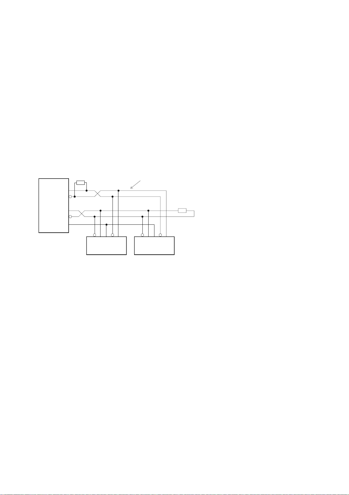
4-20mA Inputs
Each 4-20mA has a 250 ohm input connected to the signal ground as shown
below. When the instrument is AC powered, there is sufficient current from the
DC output to power up to three current loops. If more loops are to be powered,
an external DC power source is required.
Powering from the Internal DC Supply
MODEL 415
Set Supply to 24V out
11
+
+
P
-
∆
P
-
3
7
12
When using only one 4-20mA flow input, the signal must be connected to
terminal 3 as shown above
Shielding: When shielding the input signals, the shield should be connected to
the case earth and not connected at the transmitter end (ie. ground
at one end only).
Page 71

Powering from an External Supply
12-24 VDC
+
-
Flow 1 (CH3)
+
-
∆
P
High Flow
Input Circuits 69
MODEL 415A
3
P
∆
T
P
Flow 2 (CH1)
-
Low Flow
Temperature
-
(CH0)
Pressure
-
(CH2)
14
4
250
7
ohm
250
ohm
+
+
+
250
ohm
250
ohm
2
Signal Ground
The above diagram shows an installation with dual D. P. transmitters to measure
flow. When using only one 4-20mA flow input, the signal must be connected to
terminal 3 only.
Page 72

70 Input Circuits
6.3 REMOTE SWITCHES (Model 415A Only)
Remote push-buttons can be connected to the Model 415A to duplicate the
switches on the front panel.
The switches are wired as follows:
2
RESET
5
DISPLAY
6
Page 73

Installation 71
7. INSTALLATION
7.1 GENERAL
Terminal designations for the Model 415 Flow Computer are given on the
following pages. The cutout hole in the panel should be 5.5" (139mm) wide x
2.6" (67mm) high. Two side clips are supplied to secure the instrument into the
panel.
A case earthing point is provided via an earth lug on the side of the case. Note
that this earthing point is for the case only and there is complete electrical
isolation between this point and all electronic circuits. For EMC purposes, or
when the instrument is connected to mains, this point must be connected to a
good earth using a multi-stranded, braided wire or strap. All relay outputs are
totally isolated from the case and from the internal circuitry.
A Supply Output voltage is provided to power sensors. This output will provide a
regulated voltage of 8 to 24 volts and the voltage is adjustable by means of the
potentiometer on the rear panel. Maximum current is 65mA and the instrument
comes with the voltage factory set at 24 Volts. When the instrument is powered
from a DC power source, the maximum output voltage on the Supply Output is
the DC Input Voltage less 3.5 volts.
The instrument will operate from either 14 - 28 volts DC or from the mains. The
mains voltage is factory set to either 95 - 135 VAC (110 VAC nominal) or 190 260 VAC (220 VAC nominal). An internal mains transformer provides full
isolation between the mains and the electronic circuits.
The DC Ground terminal 12 provides a common ground for the 14 - 28 Volt
power input, the 8 - 24 Volt output and the pulse output.
It is good practice to use shielded cables for all signal connections to the Model
415. Care must be taken to separate signal cables from power cables so as to
minimise interference.
Overall shields should be connected to the case earth at the instrument end only.
This connection should be as short as possible and connected to the earthing lug
on the side of the case.
Page 74

72 Installation
In order to comply with the requirements for Electromagnetic Compatibility as
per EMC-Directive 89/336/EEC of the Council of European Community, this
wiring practice is mandatory.
Although it is also possible to connect shields to the signal ground (terminal 2)
this practice is not in accordance with EMC directives.
RC Networks for Interference Suppression
When driving highly inductive loads with the relay outputs, it is recommended
that RC suppression networks (often called "Snubbers") are used for two reasons:
To limit the amount of electrical noise caused by arcing across the
contacts which may, in extreme cases, cause the microprocessor to act
erratically.
To protect the relay contacts against premature wear through pitting.
RC suppression networks consist of a capacitor and series resistor and are
commonly available in the electrical industry. The values of R and C are
dependant entirely on the load. However, if the user is unsure of the type of
snubber to use, values of 0.25uF and 100 ohms will usually suffice. Note that
only mains approved RC suppression networks should be used.
The basic principle of operation is that the capacitor prevent a series of sparks
arcing across the contact as the contact breaks. The series resistor limits the
current through the contact when the contact first makes.
Page 75

Installation 73
7.2 WIRING DESIGNATIONS FOR THE MODEL 415
Terminal Model 415R Model 415A
1 Calibration Link Calibration Link
2 Signal Ground Signal Ground
3 Flow 1 (4-20mA) Flow 1 (4-20mA)
4 PT100 I (+) Temperature (4-20mA)
5 PT100 Signal (+) Reset Switch
6 PT100 Signal (-) Display Switch
7 Pressure (4-20mA) Pressure (4-20mA)
8 Flow Common (-) Flow Common (-)
9 Flow Pulse Input (+) Flow Pulse Input (+)
10 Pulse Out Pulse Out
11 DC Power Out (8-24V) DC Power Out (8-24V)
12 DC Ground DC Ground
13 DC Power Input DC Power Input
14 PT100 I (-) Flow 2 (4-20mA)
Note: When using a single 4-20mA flowmeter, it is connected to
terminal 3. The second 4-20mA flow input on terminal 14 is only
used when there are dual 4-20mA inputs. In this case, terminal 3
becomes the High Flow input and terminal 14 is used for the low
flow.
Terminal Analog Flow Output (4-20mA) RS232/422/485
20 Not To Be Used RS232 Signal Ground
21 0 Volts RS232 Data In
22 0-10 Volts RS232 Data Out
23 -12 Volts RS422/485 (-) Data Out
24 I(-) RS422/485 (+) Data Out
25 I(+) RS422/485 (-) Data In
26 +15 Volts RS422/485 (+) Data In
27 Not To Be Used RS232 CTS
Page 76

74 Installation
Terminal Relay Option
31 High - Normally Open
32 High - Normally Closed
33 High - Common
34 Low - Normally Open
35 Low - Normally Closed
36 Low - Common
Page 77

Appendix 75
APPENDIX
PROPERTIES OF SELECTED GASES
Sp. Gravity Critical Temperature Critical Pressure
G °C °F kPa psia
Acetylene 0.8990 35.17 95.3 6140 890.6
Air 1.0000 -140.4 -220.8 3769 546.7
Ammonia 0.5880 -168.0 -270.4 11277 1637.7
Argon 1.3793 -122.3 -188.2 4873 706.9
Butane 2.0054 153.0 307.4 3648 529.1
Carbon Dioxide 1.5196 31.06 87.9 7376 1069.9
Carbon Monoxide 0.9671 -140.3 -220.5 3496 507.0
Chlorine 2.4482 143.8 290.9 7701 1116.9
Ethane 1.0382 32.28 90.1 4884 708.4
Ethylene 0.9686 9.28 48.7 5036 730.4
Helium 0.1381 -267.9 -450.2 228.99 33.21
Helium-4 0.1382 -267.9 -450.3 226.8 32.9
Hydrogen 0.0696 -239.9 -399.9 1296.9 188.1
Hydrogen Chloride 1.1898 51.44 124.6 8313 1205.7
Hydrogen Sulfide 1.1767 100.1 212.1 8751 1269.2
Methane 0.5539 -82.56 -116.6 4600 667.2
Neon 0.6969 -228.8 -379.8 2756 399.7
Nitrogen 0.9672 -146.9 -232.5 3394 492.3
Nitrous Oxide 1.5199 36.5 97.7 7265 1053.7
Oxygen 1.1048 -118.6 -181.4 5046 731.9
Propane 1.5226 96.67 206.0 4246 615.8
Page 78

76 Appendix
Propylene 1.4529 91.83 197.3 4620 670.1
Sulphur Dioxide 2.2119 157.7 315.8 7883 1143.4
Xenon 4.5334 16.56 61.8 5836 846.5
Page 79

Index 77
Index
4-20mA Inputs, 68
4-20mA Output, 39
405GS, 7
405ST, 7
A
Analog Inputs, 67
ASME, 26
Atmospheric
Pressure, 61
C
Calibration
Certificate, 33
Calibration Routine, 50
Coils, 66
Compressibility, 24
Computer, 47
Cutoff, 60
D
Data Logging, 48
Date Format, 46
Decimal Points, 60
Default Display, 14, 59
Density, 16
DIL Switch, 62
Dimensions, 10
Display, 10
Display Contrast, 59
Dual Differential
Pressure, 18, 28
E
Earthing Point, 71
External Supply, 69
F
Filtering, 31
Floating Point
Numbers, 51
Flow Correction, 60
Flow Equations, 16
Flow Input, 62
Flow Parameters, 51
Flow Signal Type, 60
Fluctuations, 31
Front Access, 59
Front Reset, 59
G
Gas Parameters, 51
Gases, 75
General Gas, 24
General Setup, 51
Ground Terminal, 71
I
Ideal Gas Law, 22
IFC Formulation, 26
Impulse Counter, 38
Input Circuits, 62
Installation, 71
Interference
Suppression, 72
Isolation, 39, 71
K
K-factor Range, 10
L
Laminar Flow Tubes, 35
Linear Interpolation, 33
Logic Signals, 62
M
Mass, 20
Model Number, 9
Molecular Weight, 16
Multipoint
Communication, 44
N
Natural Gas, 25
Non-Linearity
Correction, 33
NX-19, 7
O
Offset, 61
Open Collector, 62
Options, 51
Orifice Plates, 17, 27
Output Pulse, 37
Output Voltage, 71
P
Pitot Tubes, 17, 27
Power Requirements, 10
Pressure Input, 11, 61
Printer, 46
Properties, 75
Protocol, 46
Protocols, 43
Proximity Switches, 62
Pulse Output, 12
Page 80

78 Index
R
Transducer Supply, 10
Turbine, 17
Redlich-Kwong, 7
Reed Switches, 62
Relay Output, 49
Remote Switches, 70
RS232, 43
RS232/422/485
Interface Option, 43
RS422, 43
RTD Input, 67
S
Saturated, 26
Setup Parameters, 50
Shielding, 68
Snubbers, 72
Span, 19
Specific Enthalpy, 26
Specific Gravity, 16
Specific Volume, 26
Specification, 10
Standard Conditions, 16
Steam Measurement, 26
Steam Turbines, 27
Supercompressibility
Factor, 25
Superheated, 26
Symbols, 5
V
VA Flowmeters, 35
Vortex, 17, 27
W
Wiring Designations, 73
T
Target
Flowmeters, 17, 27
Temperature
Measurement Range, 11
Temperature Offset, 61
Test, 51
Timebase, 59
 Loading...