

Page 1

BATCH CONTROLLERS
MODEL 414A
November 1995
Page 2

Page 3

CONTENTS
1. Introduction 3
1.1 Model Number Designation 4
2. Specification 5
3. Operation 7
3.1 Front Panel Operation 8
3.2 Batch Operations 11
3.2.1 Control Relay Outputs 13
3.2.2 Signal Timeout 14
3.2.3 End of Batch 15
3.2.4 Auto Restart 16
3.2.5 Automatic Overrun Compensation 17
3.3 Calculation of Rate and Total 18
3.3.1 Analog Input 18
3.3.2 The Cutoff Point 19
3.3.3 Filtering 20
3.4 Total Conversion 22
3.5 The Output Pulse and Flow Alarm 23
4. Options 25
4.1 The RS232/422/485 Interface Option 25
4.1.1 Hardware 25
4.1.2 Multipoint Communication 26
4.1.3 Communication Protocol 28
5. Calibration 30
5.1 Programming the Setup Parameters 32
5.2 Entering the Batch Parameters 34
5.3 Programming Options 36
5.4 Checking the Input Signal 38
Page 4

6. Input Circuits 39
6.1 The Signal Input 39
6.2 Remote Switch Inputs 41
7. Installation 42
7.1 General 42
7.2 Wiring Designations for the Model 414A 44
8. Trouble Shooting 45
8.1 Error Codes 47
Index 48
Page 5

Introduction 3
1. INTRODUCTION
The Model 414A Batch Controller accepts analog flow signals and automatically
controls the batching of fluids via a one or two stage control valve.
The instrument is extremely flexible and easy to operate, with a four key, front
panel operation that enables the batch quantity to be set, and batches to be
started or stopped.
The Batch Controller is a microprocessor based instrument which measures
4-20mA, 0-20mA, 1-5 Volt or 0-10 Volt signals from flowmeters and pressure
transducers. The instrument can be programmed to display directly in
engineering units and includes such features as linear or square law calculation,
integration and digital filtering.
The 4-20mA, 0-20mA, 1-5 Volt and 0-10 Volt input signals are isolated from the
supply rails and outputs, and may therefore float independently. This ensures
that the input will be compatible with all transmitters and can be used in current
loops which have more than one receiver.
The instrument is fully programmable, with all calculation constants set via the
front panel switches and stored in a non-volatile memory which will retain data
indefinitely. The user can program such parameters as span, zero, filtering
levels, display resolution and cutoff points.
This instrument conforms to the EMC-Directive of the Council of European
Communities 89/336/EEC and the following standards:
Generic Emission Standard EN 50081-1 Residential, Commercial & Light
Industry Environment.
Generic Emission Standard EN 50081-2 Industrial Environment.
Generic Immunity Standard EN 50082-1 Residential, Commercial & Light
Industry Environment.
Generic Immunity Standard EN 50082-2 Industrial Environment.
In order to comply with these standards, the wiring instructions in Section 8.1
must be followed.
Page 6

4 Introduction
1.1 MODEL NUMBER DESIGNATION
The Model number of an instrument describes which input and output options
are installed and the AC mains voltage rating.
Model 414 A. 1 0 E B
B for Backlite
C for Conformal Coating
E for 220/240 VAC
A for 110/120 VAC
D for DC Power Only
Options
0 for no option
2 for RS232/422/485
Mounting
1 for panel mounting
2 for field mounting
3 for explosionproof
The Model Number of the instrument is displayed on first entering the
Calibration Mode (see Section 5).
Page 7

Specification 5
2. SPECIFICATION
General
Display: 6 digit LCD. 0.7" (17.8mm) high digits.
Display Update Rate: 0.25 seconds.
Transducer Supply: 8-24VDC field adjustable.
50mA maximum.
Power Requirements: 11.5 to 28.5 volts DC.
130 mA typical current (no options).
AC Mains: Set internally to 95-135 VAC or
190-260 VAC.
Operating Temperature: 0 to 55°C standard.
Dimensions: 5.7" (144mm) wide x 2.8" (72mm) high x
7.0" (178mm) deep.
Cutout: 5.5" (139mm) wide x 2.6" (67mm) high.
Analog Input
Input: 4-20mA, 0-20mA, 1-5 Volt or 0-10 Volt.
The input circuit is floating and isolated from
the power supply and outputs.
Span: 0.1000 to 50000.0000.
Zone: 0.0000 to 50000.0000.
Accuracy: 0.075% of full scale.
Self-Calibrating: An internal reference is sampled every 10
minutes. Temp Co-efficient is 40ppm/C.
Aging is 20ppm/1000 hrs.
Integration: The rate is integrated with a timebase
selectable to be in days, hours, minutes or
seconds.
Cut-off: A cut-off point can be set below which the
rate is not integrated.
Page 8

6 Specification
Relay Outputs
Maximum Switching Power: 1250VA.
Maximum Switching Voltage: 250VAC, 30VDC.
Maximum Switching Current: 5 Amps.
Pulse Output
Pulse Width: 10mSec (negative going pulse).
Maximum Duty Cycle: 49 pulses per second.
Output: An open collector transistor will sink
100mA.
Scaling: The pulse output is scaled and outputs one
pulse each time the accumulated total
increments.
Page 9
Operation 7
3. OPERATION
The Model 414A Batch Controller uses a low power CMOS microprocessor to
perform all control functions and calculations.
The instrument is fully programmable with all operating parameters and
calculation constants user programmable. (See Section 5 entitled "Calibration"
for information on programming.) All parameters and constants are stored in a
non-volatile memory which retains data without battery backup for a minimum
of 10 years.
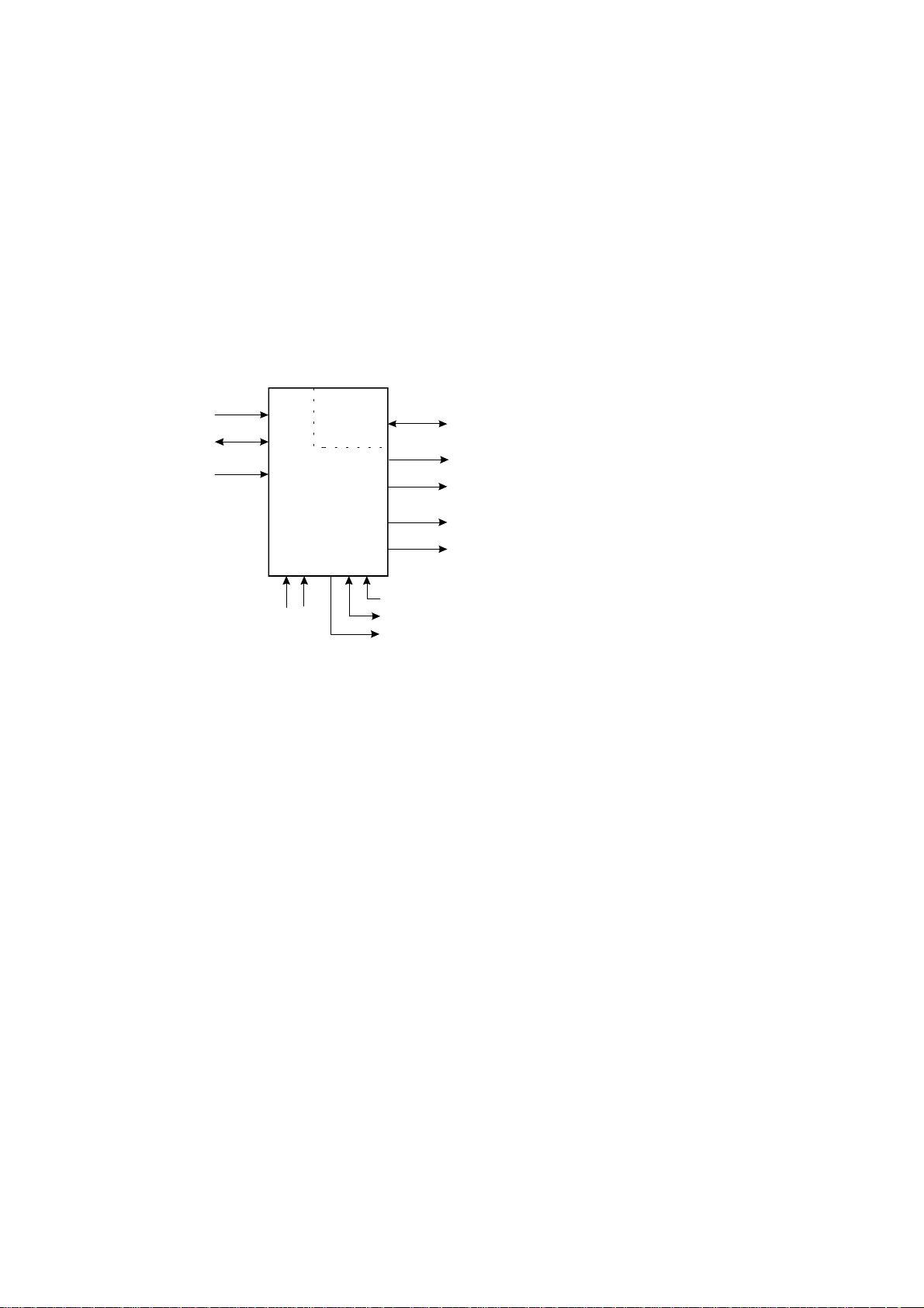
A block diagram of the instrument is shown below.
4-20mA
(0-20mA)
Signal
Common
0-10 V
1-5 V
Model 414A
110/220V
AC Main s
RS232/422
Option
Relays
RS232/422
Output
EOB
Control
Relay Outputs (2)
Pulse
Output
Flow Alarm
DC Input Power
DC Power Ground
DC Power Output to Sensors
Page 10

8 Operation
3.1 FRONT PANEL OPERATION
The four key operation of the Batch Controller is straight forward.
SETTING THE BATCH QUANTITY
The Batch quantity is programmed as follows:
Switch Action Display Comments
Press BATCH SET Batch "Batch" is displayed for one second
followed by the batch quantity last
entered. The Batch Set LED lights.
"1" 2345 The most significant digit flashes
indicating that it can be changed.
Press "2" 2345 Pressing the DISPLAY key will
increment the digit. (The up arrow on
the Display key indicates to increment
digit.)
Press 2 "2" 345 Pressing the RUN key will change digit
and enables the next digit to be
incremented. (The right arrow on the
RUN key indicates to change digit.)
Press BATCH SET Set Once the desired number is entered,
press the BATCH SET key to return to
the Run mode. The Batch Set LED will
extinguish.
Once programmed, the Batch quantity will be retained in the non-volatile
memory and will not alter until changed by the user.
Page 11

Operation 9
The Batch quantity can only be set while the instrument is in non-operational
state such as when the batch is complete, or if the batch process has been
interrupted. However, the Batch key can be pressed while in the run state and
the Batch quantity checked. All digits will flash to signal the quantity cannot be
changed.
STARTING A BATCH
To start the process the RUN key is pressed. The Run LED will light and the
instrument will begin to totalise from zero or, if programmed for the count down
mode, the display will decrement from the batch quantity.
The batcher has two output relays and these are energised and de-energised as
described in section 3.2.
STOPPING
The process can be stopped at any time by pressing the STOP switch. Once the
process has been interrupted in this way it can be continued by pressing the RUN
switch or the process can be aborted and the instrument reset by pressing the
STOP switch a second time.
When the process is interrupted, the STOP LED will flash to prompt the
operator to either restart or abort the batch.
RESETTING
The instrument can be programmed to reset in one of two ways.
At the end of a batch, the STOP key must be pressed to reset the Batch
Total. If the instrument is programmed to count down, the Batch
Total will then revert to the preset quantity. If it is programmed to
count up, the Batch Total will clear to zero.
If Auto Reset is programmed, the Batch Total will automatically reset
when the RUN key is pressed and then commence the next batch.
Page 12

10 Operation
DISPLAYED INFORMATION
The display will normally show the Batch Total, which is the total count for the
current batch and is reset on each new batch.
The DISPLAY key can be used to display the following additional information:
Rate
On the first press of the DISPLAY key, the display shows RATE for
one second followed by the flowrate.
Accumulated Total
On the next press of the DISPLAY key, the display shows ACC for
one second followed by the actual total. The Accumulated Total
cannot be reset during normal operation.
LIMIT ON BATCH SIZE
To prevent accidental entry of large batch quantities, a maximum batch limit can
be programmed during calibration. The operator is then prevented from entering
a batch quantity which exceeds this value.
Page 13
Operation 11
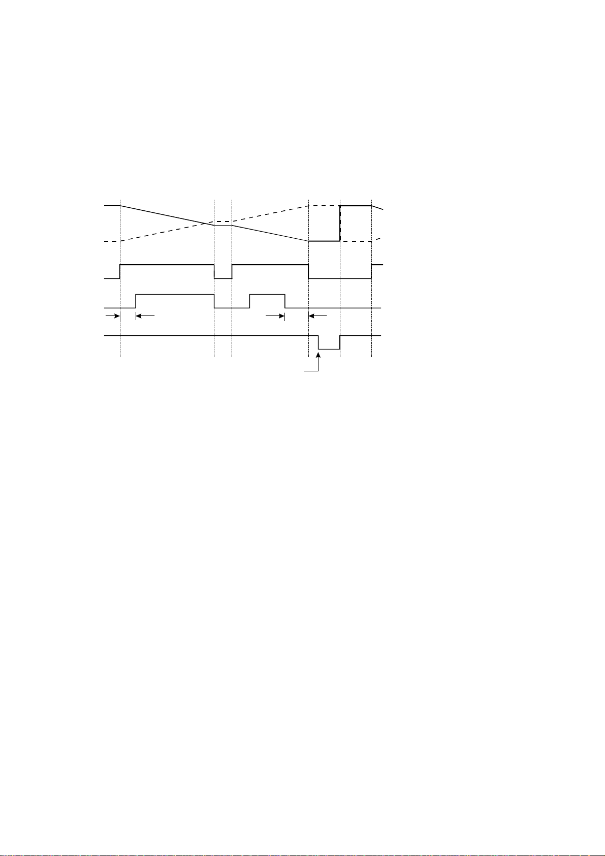
3.2 BATCH OPERATIONS
The Batch Control functions can be programmed, during Calibration, to operate
in one of two ways.
1. At the end of the batch, the STOP key must be pressed to reset the Batch
Total. (This must be done before another batch can be started.)
Run Stop Run
Count Down
Count Up
Relay 1
Relay 2
Start Time
End of
Batch
PAUSE
Presto p
Quantity
End of Batch
Batch
Quantity
Reached
Stop Run
Page 14
12 Operation
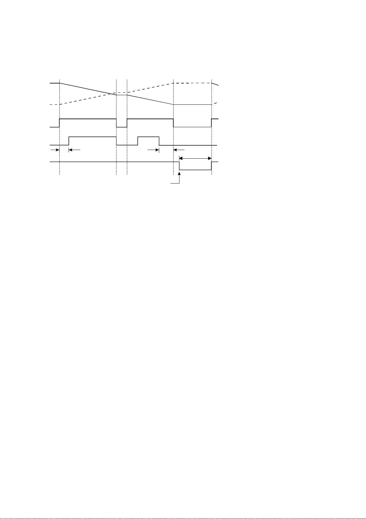
2. If Automatic Reset is programmed, a new batch is commenced each time the
RUN key is pressed.
Batch
Quantity
Reached
Run
Auto Restart
Time
Run Stop Run
Count Down
Count Up
Relay 1
Relay 2
Start Time
End of
Batch
PAUSE
Presto p
Quantity
End of Batch
The Batch Controller can also be programmed, during Calibration, to either
count up from zero on each batch, or to count down from the preset batch
quantity.
Page 15

Operation 13
3.2.1 Control Relay Outputs
The two output relays can be set up to control a single valve or a dual valve with
slow stop and/or slow start. Alternatively, the second relay can be used to
control a pump.
The relay operation is shown on the previous two pages.
A time delay between the Start and the time when relay 2 energises can be
programmed to provide a soft startup. The delay can range from 0 (no delay) to
79 minutes and 59 seconds.
A Prestop quantity (ie. the quantity to the end of the batch) can also be
programmed to provide a slowdown of flow at the end of the batch, thereby
enabling precise quantities to be batched.
The process can be stopped at any time by pressing the STOP key, whereby both
relays will immediately de-energise. The process can then be aborted and the
batcher reset by pressing the STOP key again, or the process continued by
pressing the RUN key.
If the process is continued and the instrument was previously in the slow start or
main control phases (ie. not the prestop phase), the timer will be reset and a slow
start will occur with a full time delay to ensure a correct start up. The totals will
not be reset and the batch quantity will remain unchanged.
Page 16

14 Operation
3.2.2 Signal Timeout
The Signal Timeout period defines a time interval which is used to detect if the
flow has stopped. If there is no signal input for a time greater than the Signal
Timeout period, the flow is deemed to have stopped. A Signal Timeout period
has two functions:
To detect the loss of signal midway through a batch when the relays
are energised. In this case, the Batcher will enter a Flow Alarm
condition and de-energise the relays.
After the preset batch quantity has been reached and the relays
de-energised, some overrun of flow may occur due to slow valve
closure, etc. In this case, the Signal Timeout is used to determine
when the flow has ceased and thereby accurately determine the
amount of overrun.
The instrument enables the user to program a time interval of up to 99 seconds to
detect an absence of signal input. If the Signal Timeout is set to 0, this
function is disabled.
Flow Alarm
If the Signal Timeout is set at greater than 0, and loss of signal is detected
midway through a batch, a Flow Alarm signal is output on terminal 7. In
addition, both relays are de-energised. The Flow Alarm output and condition is
maintained until acknowledged by pressing the STOP switch. The alarm
condition is also signalled to the operator by the flashing STOP LED. Once
acknowledged, process can then be reset via the STOP switch or continued by
pressing the RUN key.
Page 17

Operation 15
3.2.3 End of Batch
An End of Batch is defined as being when the Batch Quantity is reached, the
flow has stopped and the Signal Timeout period has expired.
If the Signal Timeout is set to zero, the End of Batch is defined as being when
the Batch Quantity is reached, regardless of whether the flow has stopped.
The Batch Controller cannot be reset or restarted until the End of Batch and
similarly, for an RS232/422/485 interface, data will not be output until the End
of Batch has been determined. Consequently, it is strongly recommended that
the Signal Timeout period be kept fairly short.
Signal
End of
Batch
End of
Batch
(Timeout = 0)
Batch Quantity
Reached
4mA (0V)
Signal Timeout
Reset
End of Batch Signal
An End of Batch signal from an open collector transistor is output on terminal 30
and the output is identical to the Output Pulse circuit as shown in section 3.5.
When reaching the End of Batch, the output transistor is switched on, and will
remain in the "on" state until the instrument is reset.
Page 18

16 Operation
3.2.4 Auto Restart
The Batch Controller can be programmed to continually repeat the batch
process. This mode of operation is selected during the programming procedure.
The process is started by pressing the RUN key whereby the normal batch
operation is commenced. After reaching the End of Batch (see section 3.2.3),
the Batch Controller will then wait for a pre-programmed period before
automatically resetting and starting the batch process once again.
The STOP button can be pressed at any time to interrupt the batching process
and continued using the RUN key. If, however, the process is to be aborted, the
STOP key is again pressed. The Batch Controller is reset and to restart the auto
batching process the RUN key is pressed.
Page 19

Operation 17
3.2.5 Automatic Overrun Compensation
The Batch Controller can be programmed to automatically compensate for any
overrun at the end of a batch.
Typically, this could be due to the slowness of a valve to close or a pump to stop
pumping on receiving a signal from the Batch Controller. The result is that the
batch quantity will always read higher than the batch quantity set.
The Automatic Overrun Compensation can be enabled or disabled during the
Calibration routine and this feature should only be used if the overrun is
repeatable. The user is cautioned against using Automatic Overrun
Compensation if the overrun is erratic, such as may occur with changing back
pressures or sticking valves.
In calculating the amount of overrun to be compensated for, the Batch Controller
uses the average overrun on the last three batches.
The overrun is defined as the difference between the batch quantity set by the
user and the batch total once the flow has stopped.
With Automatic Overrun Compensation, the Signal Timeout must be set to a
value greater than zero.
Once the Batch Controller de-energises both relays, the instrument looks for a
Signal Timeout, indicating that the flow must, therefore, have stopped. It then
uses the overrun quantity measured during this period and averages this together
with the overrun on the last two batches. The resulting value is then subtracted
from the next batch.
Page 20

R
R
R
18 Operation
3.3 CALCULATION OF RATE AND TOTAL
3.3.1 Analog Input
The flowrate, R, is calculated as follows:
= SA + C
= SA+C
or if an open channel relationship is selected.
At the minimum input (ie. 4mA, 0mA, 1 Volt or 0 Volts), A = 0, and at the
maximum input (ie. 20mA, 5 Volts or 10 Volts), A = 1.
The Span, S, can be set during calibration anywhere in the range of 0.1000 to
50000.0000 and the Zero value, C, set in the range 0.0000 to 50000.0000.
The Span, S, can be selected to display rate in any units desired, such as
litres/minute or kilograms/hour. This also means that the Total will be displayed
with the same unit of volume, ie. litres or kilograms.
= SAn+C
where A= the input value.
S= the span.
C= the zero.
n = a variable power which can be programmed between 0 and
9.999.
if the linear relationship is selected.
if a square law relationship is selected.
Page 21

R
R
A
I
Operation 19
3.3.2 The Cutoff Point
Because many transducers do not always exactly transmit 4mA (0mA, 1V or 0V)
when they are at zero rate, it is often necessary to define a rate below which no
integration takes place. This is termed the cutoff point and is programmed as a
percentage of the Span, S.
For example, if S = 2200 kg/min with an offset of 100 kg/min in a square law
system, and the cutoff point is set at 20.0%, the actual cutoff rate Rc can be
determined as follows:
The cutoff rate is defined as:
At 20% cutoff:
c =
2200
A + 100
c = 2200 x 0.2 + 100
= 540 kg/min
The value of A which would produce this cutoff is:
= 0.04
and the input signal would be:
= 16mA x 0.04 +4mA
= 4.64mA
(since 0.04 = 0.2)
Page 22

20 Operation
3.3.3 Filtering
Frequency fluctuations caused by pulsating flow through a flowmeter, often
makes the Rate impossible to read with any precision. The Batch Controller has
a digital filter which will average out these fluctuations and enable the Rate to be
read to four digit accuracy. The ability to select a suitable filtering level means
that highly accurate and stable readings can be obtained without excessive lag.
The diagram below shows a pulsating signal input together with the effect of
filtering.
Rate
Filtered Response
Unfiltered Response
Time
As a guideline to the degree of filtering to be used, the following table shows the
response to a step change in input. The value, A, is the filter constant which is
programmed during the Calibration routine. The times for the display value to
reach 90% and 99% of full swing are given in seconds, for different values of A.
Page 23

Operation 21
A 90% 99%
100
212
424
636
10 5 11
15 8 17
20 11 22
25 14 28
35 20 40
45 25 51
60 34 69
75 43 86
90 52 103
99 57 113
Table 1 - Response to a step Input (in seconds).
Note that if A is set to 1 there is no filtering of the input signal.
Page 24

22 Operation
3.4 TOTAL CONVERSION
The Total Conversion feature enables the rate to be displayed in one engineering
unit (eg. gallons/minute) and the totals to be displayed in another engineering
unit (eg. barrels).
The Scaling Factor is always programmed in the unit relating to Rate
Total Conversion constant is a division factor which can be used to convert the
totals to the different unit. The Total Conversion factor affects the net,
accumulated and gross totals and is limited between 0.01 and 2000.
For Example.
If the Rate is required in gallons per minute:
1. The Scaling Factor would be programmed as pulses per gallon.
2. The timebase would be programmed as minutes.
If the Totals are required in barrels:
3. The Total Conversion factor is programmed as 42 (there are 42 gallons in a
barrel). All totals, including the Batch Quantity and Batch Total, will now be
in barrels.
Some common units are given below together with the Total Conversion
constant (TOTCON) which should be programmed.
Rate*
Gallons (US)/ Barrels (oil) 42.000
Litres/ Kilolitres 1000
ml/ Litres 1000
Mgallons/ Acre-feet 0.32587
Totals TOTCON
, and the
* Units per second, minute, hour or day. The timebase is programmed
separately during Calibration.
Page 25

Operation 23
3.5 THE OUTPUT PULSE AND FLOW ALARM
An OUTPUT PULSE is available on terminal 10 for driving remote counters
and produces a pulse each time the Accumulated Total increments by one digit.
For example, if the Accumulated Total has a resolution of 0.01 litres, a pulse is
produced each 0.01 litres.
The pulse is a current sinking pulse of approximately 10mSec produced by an
open collector transistor. The maximum pulse rate is limited to 49 pulses per
second and the resolution on the accumulated total must be set so that the
accumulated total increments at less than 49 counts per second.
Note that due to the uneven pulse output spacing on this output, the pulse output
cannot be used to drive rate indicators.
The FLOW ALARM uses an identical circuit to the Output Pulse, and is on
terminal 7.
The Flow Alarm will output an alarm condition if the flow times out during a
batch (ie. there is no flow registered for a time greater than the Signal Timeout
period, providing the Signal Timeout is greater than 0).
The Flow Alarm output will switch "on" (ie the signal goes low) whenever an
alarm condition exists. The Alarm will switch "off" (ie the signal goes high)
when the alarm is reset by pressing the STOP key.
Page 26

24 Operation
Connection of Output Pulse and Flow Alarm are as follows:
Relay or
Impulse Counter
5.6 ohms
33V
Zener
12
DC Supply
Driving an External Relay or Impulse Counter
DC Supply
Out (8-24V)
5.6 ohms
33V
Zener
11
External Load
Resistor 10K
Logic Input
2
Driving a Logic Input such as a PLC or Electronic Counter
Page 27

Options 25
4. OPTIONS
4.1 THE RS232/422/485 INTERFACE OPTION
With this option installed, the circuits for both the RS232 and RS422/485 are
provided as standard. They can be used to interface to both printers and
computers and a number of standard protocols are built into the instrument.
4.1.1 Hardware
The following diagram provides an overview of the RS232/RS422/485
communications hardware. All three interfaces are available on the rear terminal
strips and the user can select either one by making the appropriate connections.
The RS232 interface is primarily used with printers or for simple communication
with a computer over a short distance. The RS422 and RS485 interfaces are
used for communication over a long distance or in applications requiring
multipoint communication.
(+)
24
(-)
23
(+)
26
(-)
25
Data In
21
Data Out
22
27 CTS
20
Ground
RS422 Out
RS422 In
RS232
Page 28

26 Options
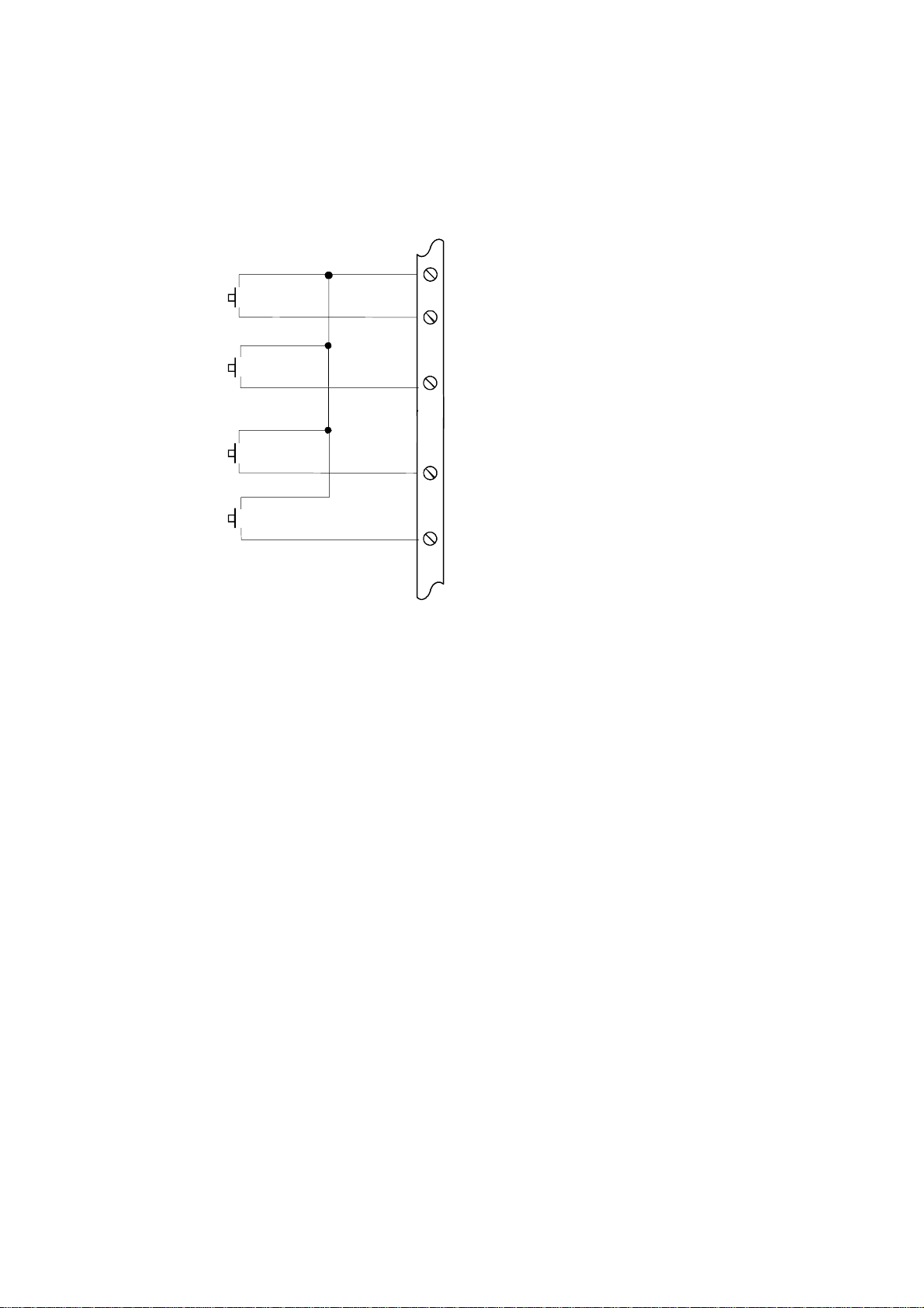
4.1.2 Multipoint Communication
Multipoint Communication is a system whereby a number of instruments can be
addressed over a dual twisted pair interface. Up to 32 instruments can be
connected to a common bus using the RS422 and RS485 interfaces as shown
below.
To convert the RS422 interface to an RS485 interface, the RS422 (-) Data In
Terminal must be connected to the RS422 (-) Data Out Terminal and the RS422
(+) Data In Terminal must be connected to the RS422 (+) Data Out Terminal.
These connections will convert the RS422 4 wire interface to the RS485 2 wire
interface, as shown in figure 2.
Each instrument can be programmed with a unique address which is used by the
Master Controller (ie IBM/PC) to identify each instrument. The Controller will
send the address down the line and will alert the relevant instrument.
Subsequent software protocol will control the flow of data between the
Controller and the Instrument.
Host
Compu ter
Load
120 ohms
400 Series
Instrument
Twisted Pair
Figure 1 RS422 Interface
Load
120 ohms
400 Series
Instrument
Page 29

Twisted Pair
Options 27
Host
Compu ter
Gnd
+
Load
120 ohms
-
+-
-
Gnd
In
400 Series
Instrument
Out
+
-
+--+
Gnd
In
Out
400 Series
Instrument
Figure 2 RS485 Interface
Page 30

28 Options
4.1.3 Communication Protocol
The Model 414A has a real time clock and enables the time and date to be set
and printed on tickets. The date format can be European (days/months/years) or
USA (months/days/years), while the time is on a 24 hour clock.
Note that the clock will only retain its time for 3 days minimum if there is no
power connected to the instrument. After this period, the clock may need to be
reset.
The baudrate, parity and word length can be programmed during calibration and
the user must ensure that these correspond to the setting on the printer or
computer with which the 414 is communicating.
The software protocols can be selected during Calibration to provide standard
interfaces to a number of printers and computers. Since other interfaces will
continue to be added, the user should consult the manual "The RS232/422/485
Communications Option for the 400 Series, Version 2", for the latest protocols
and printer drivers.
Printer
A ticket is printed at the end of each batch. Protocols are provided to drive the
following printers:
1 Standard Computer Printer (Note that the printer must have an
RS232 Serial Interface).
2 EPSON CTM290 Slip Printer.
3 Contrec Model 624.
4 EPSON TM290-2 Slip Printer
5 Contrec Model 632-2.
6 Syntest SP-210.
The tickets can also be printed with a number of different units, including litres
and gallons. The units are selectable from a pre-programmed list.
Page 31

Options 29
A CTS input is provided, and will prevent the instrument from transmitting any
further characters to a printer if the printer buffer is full. The CTS input is
usually connected to the "Data Buffer Full" output from the printer.
If the printer buffer is large enough to handle the messages output from the
Batch Controller, then this input need not be used and can be left unconnected.
Computer
The instrument receives and transmits messages in ASCII, with all command
strings to the instrument terminated by a carriage return. While replies from the
instrument are terminated with a carriage return and a line feed.
Xon/Xoff protocol is also supported, and the instrument will automatically
determine if the message sent by the host computer is preceded by an Xoff
character. If it does recognise an Xoff as the first character of a command string,
the instrument will automatically switch to Xoff/Xon protocol, and begin & end
all messages with Xoff and Xon characters respectively. Xoff/Xon protocol is
only available when the RS232 interface is selected.
During Calibration, the instrument can be programmed to operate in a full
duplex or half duplex transmission mode. In full duplex mode, all commands
sent to the instrument will be echoed back to the host computer. In half duplex,
the commands are not echoed.
For more information on the computer interface please consult the manual "The
RS232/422/485 Communications Option for the 400 Series, Version 2".
Page 32

30 Calibration
5. CALIBRATION
The Calibration routine enables the Setup Parameters to be programmed, as well
as enabling the input signals to be checked.
The calibration routine can be entered in two ways:
1 By connecting a wire link (or switch) to the rear terminal strip
across terminals 1 and 2 or,
2 By pressing the STOP key and while still holding, press the
DISPLAY key. Both keys must then be held for approximately 6
seconds. This second method of access can be disabled during the
calibration so that it is only possible to enter the calibration routine
via the link across terminals 1 and 2.
The key switch actions during Calibration are as follows:
RUN will change a flashing digit, to the next digit.
DISPLAY will increment a flashing digit or change a parameter
selection.
BATCH SET will reset a flashing digit to zero.
STOP will step through the program sequences.
Note that the arrows in the RUN and DISPLAY key switches indicate that these
switches can be used to change and increment digits respectively.
In stepping through the program sequence, the Parameter Description is always
displayed first, followed by actual value or parameter. When a value or
parameter can be changed, it is always shown as flashing, and the LED's in the
switch panels are lit if that key switch can be used to change a value.
Page 33

Calibration 31
On first entering the Calibration routine, the display will show:
CAL Setup Program parameters (see section 5.1).
Batch Enter Batch parameters (see section 5.2)
Option Option - if installed (see Section 5.3).
Test Check Input Signals (see section 5.4)
End Exit to Normal Operation.
The user can toggle between these modes using the DISPLAY switch and by
using the STOP switch, select the appropriate mode.
To exit Calibration, step through the Setup program, Batch program or Test
program until the end, and press the STOP switch when End is displayed,
(ensure the calibration link is not connected).
Page 34

32 Calibration
5.1 PROGRAMMING THE SETUP PARAMETERS
Step Display Description Text
Ref
1 CAL
BATCH
OPTION
TEST
END
The following steps are displayed if CAL
2 RESTOT Reset all totals
3 INPUT
4-20
0-20
1-5
0-10
4 SPAN
xxx.xx
5 RBASE
xxx
6 PO. n
Lin
Sq. rt.
Op. Ch.
If Open Channel is selected Steps 7 and 8 are displayed, otherwise the program
goes to Step 9.
7 POL
Pos
Neg
8 N
x.xxx
Select the Calibrate mode to setup program
parameters.
Select Batch to enter Batch Setup parameters.
Option (if installed).
Select the test mode to check input signals.
Exit to normal operation.
is selected.
to zero.
To reset all totals (resettable and accumulated)
press the BATCH SET key once.
Select Input
for 4-20mA.
for 0-20mA.
for 1-5 V.
for 0-10 V.
The Span.
Enter the Span.
The Zero value.
Enter the Zero base value.
(Normally 0 for most flow applications).
The power of A
Select for linear input (n=1).
Select for square law (n=½).
Select for Open Channel.
Polarity.
Flow increases as the input increases.
Flow decreases as the input increases.
Value of exponent, n.
Program between 0 and 9.999.
n.
5.2
5.3
5.4
3.3.1
3.3.1
3.3.1
Page 35

Calibration 33
Step Display Description Text
Ref
9 CUTOFF
xx.x
10 F dPt Number of decimal points with which the Rate
11 t.base The Timebase
60secs
hours
days
secs
12 FILTER The filter constant
1
to
99
13 TOTCON A division factor
1 Rate and totals have the same engineering units.
x.xxxx Other factors can be programmed between 0.01
14 t.dPt Number of decimal points with which the
15 A.dPt Number of decimal points with which the
16 ACCESS
Front
No Acc
The signal Cutoff.
Enter as a % of the Span.
to be displayed between 0 to 0.00000.
with which the Span is entered
must be programmed.
units/min
units/hour
units/day
units/second
for filtering the rate display. 3.2.2
No filtering.
Very heavy filtering
to convert the totals to different
units from those used for rate (ie gallons/min and
barrels).
and 2000.
resettable total is displayed between 0 to 0.000.
Accumulated
between 0 to 0.000.
Enable access to calibration routine via the front
keyboard only.
Enable access via front keyboard.
Disable access via front keyboard.
(non resettable) total is displayed
3.3.2
is
3.2.1
3.4
Page 36

34 Calibration
5.2 ENTERING THE BATCH PARAMETERS
Step Display Description Text
1 BATCH
OPTION
TEST
END
CAL
The following steps are displayed if BATCH is selected.
2 BATCH L
xxxxxx
3 AUTO S
Off
On
xx:xx
Enter Batch Parameters.
Option (if installed)
Check Input Signals.
Exit to normal operation.
Program Setup Parameters.
Maximum Batch Size which can be
entered.
Set to 0 if no limit on batch size.
Automatic restart
Disable.
Enable.
If enabled, automatically restarts the
batch xx:xx (mins:sec) after the end of
the last batch.
feature.
Ref
5.3
5.4
5.1
3.2
3.2.4
4 START. T
xx:xx
5 PREST
xxxx
Slow start
Time, in (minutes:seconds), when
Relay 2 will energise once the batch
has started.
Prestop Quantity.
Quantity at which Relay 2 will
de-energise before the end of the batch.
(Eg. If the batch quantity is 100 litres
and Prest is 2 litres, relay 2 will
de-energise after 98 litres.)
time.
3.2
3.2
Page 37

Calibration 35
Step Display Description Text
Ref
6 COUNT
dn
up
The Batch Total
Count down from the batch quantity.
Count up from zero.
counts Up or Down.
3.2
7 T OUT The Signal Timeout
(Setting to 00 disables this feature.) 3.2.2
8 AOC
En
Dis
9 AUTO R
Off
On
Automatic Overrun Compensation.
Note that the Signal Timeout must be
greater than 0 (ie enabled) for this
feature to work.
Enable.
Disable.
Auto Reset
Restart is programmed - Step 3 above).
Batch Total must be manually reset
before starting the next batch.
The Batch can be automatically reset
and started by pressing only the RUN
key.
(not displayed if Auto
in seconds.
3.2.5
3.2
Page 38

36 Calibration
5.3 PROGRAMMING OPTIONS
Step Display Description Text
Ref
1 OPTIONS
Test
End
CAL
Batch
If the RS232/422/485 option is installed, the following will be
displayed:
2 DF
Eur
USA
Options (if installed).
Check the Input Signals.
Exit to normal operation.
Program Setup Parameters.
Set Batch Parameters.
Date Format.
European (ie. days/months/years).
USA (ie. months/days/years).
5.4
5.1
5.2
4.1
3 Date
xx:xx:xx
4 HOUR
xx:xx
5 BAUD
xxx
6 DATA
7
8
7 PARITY
NP
OP
EP
Enter date as:
Years:Months:Days.
Enter time as a 24 hour clock.
Hours:Minutes.
Baudrate
300, 600, 1200, 2400, 4800 and 9600.
Word length.
7 bits.
8 bits.
Parity.
No Parity.
Odd Parity.
Even Parity.
4.1
Page 39

Calibration 37
Step Display Description Text
Ref
8 SIGNAL
rs232
rs422
9 ID NO
0
1 - 99
10 P TYPE xx
Signal Type.
RS232.
RS422/RS485.
Unit Identification Number.
None.
Id number.
Printer/Computer Type.
00
01
02
03
04
05
20
If a Printer Protocol is selected, the following message is displayed:
10 UNIT xx
00
01
02
03
04
05
06
07
If a Computer Protocol is selected, the following message is displayed:
10 ECHO
On
Off
Standard Computer Printer.
EPSON CTM 290 Slip Printer.
Model 624 Roll Printer.
EPSON TM290-2 Slip Printer.
Contrec Model 632-2 Printer.
Syntest SP-210 Printer.
Computer.
Units of measurement printed.
None.
Litres (Ltrs).
Gallons (Gals).
Barrels (bbls).
Pounds (lbs).
Grams (gms).
Kilograms (kgs).
Tons (tons).
ECHO Command.
Echo (Full Duplex).
No Echo (Half Duplex).
Page 40

38 Calibration
5.4 CHECKING THE INPUT SIGNAL
Step Display Description Text
1 TEST
OPTIONS
CAL
BATCH
END
The following steps are displayed if TEST is selected.
2 Sr x.xx Software revision number.
Depending on the input selected, the input current or voltage will be
displayed.
Check the Input Signals.
Options (if installed).
Program Setup Parameters.
Set Batch Parameters.
Exit to normal operation.
Ref
5.3
5.1
5.2
3 4-20mA
xx.xx
0-20mA
xx.xx
1-5 Volt
xx.xx
0-10 Volt
xx.xx
If the RS232/422485 option is installed, the display will then show:
4 CLOC
xx:xx:xx
Displayed for 1 second followed by the actual
current.
Displayed for 1 second followed by the actual
current.
Displayed for 1 second followed by the actual
voltage.
Displayed for 1 second followed by the actual
voltage.
Clock.
Time in Hours:Mins:Sec.
Page 41

Input Circuits 39
6. INPUT CIRCUITS
6.1 THE SIGNAL INPUT
The basic circuit of the input is shown below. Both the current and voltage
signals are fed to a data selector but only one signal is processed, depending
upon whether a current (4-20mA or 0-20mA) or a voltage (1-5 V or 0-10 V)
input configuration is selected. The signal is fed to a voltage to frequency
convertor and transmitted to the microprocessor via an opto-coupler.
The microprocessor uses a crystal reference to provide an accurate measurement
of the incoming frequency. Once every 10 minutes a stable and accurate internal
reference is sampled and used to compensate the input. This technique ensures a
highly accurate measurement and makes periodic calibration unnecessary.
14
9
250
Ohm
8
Current
Voltage
10K
Reference
DC to DC
Convertor
Voltage to
Frequency
Microprocessor
Regulator
Isolation
Page 42

40 Input Circuits
Model 414 Batch Controller
11
9
8
2
Transmitter
+
-
4-20mA
Transmitter Powered by the Flow Computer
External Loop Power
+
Transmitter
4-20mA
-
8-24 VDC
250 ohms
Ground
Batch Control ler
9
250 ohms
8
4-20mA Loop with External Power Supply
INPUT CONNECTIONS
+
Chart Recorder
-
Page 43
Input Circuits 41
6.3 REMOTE SWITCH INPUTS
Remote push-buttons can be connected to the Model 414A to duplicate the
switches on the front panel.
The switches are wired as follows:
2
RUN
28
DISPLAY
BATCH
SET
STOP
4
5
29
Page 44

42 Installation
7. INSTALLATION
7.1 GENERAL
The terminal designations for the Model 414A Batch Controller are given on the
following pages. The cutout hole in the panel should be 5.5" (139mm) wide x
2.6" (67mm) high. Two side clips are supplied to secure the instruments into
panel.
A case earthing point is provided via an earth lug on the side of the case. Note
that this earthing point is for the case only and there is complete electrical
isolation between this point and all electronic circuits. For EMC purposes, or
when the instrument is connected to mains, this point must be connected to a
good earth using a multi-stranded, braided wire or strap. All relay outputs are
totally isolated from the case and from the internal circuitry.
The two output relays are changeover relays and both the "normally open" and
the "normally closed" terminals are available on the rear terminal strips. All
relay outputs are totally isolated from the case and from the internal circuitry.
A Supply Output voltage is provided to power sensors. This output will provide
a regulated voltage of 8 to 24 volts and the voltage is adjustable by means of the
potentiometer on the rear panel. Maximum current is 50mA and the instrument
comes with the voltage factory set at 24 Volts. When the instrument is powered
from a DC power source, the maximum output voltage on the Supply Output is
the DC Input Voltage less 3.5 volts.
The instrument will operate from either 12 - 28 volts DC or from the mains. The
mains voltage is factory set to either 95 - 135 VAC (110 VAC nominal) or 190 260 VAC (220 VAC nominal). An internal mains transformer provides full
isolation between the mains and the electronic circuits.
The DC Ground terminal 12 provides a common ground for the 12 - 28 Volt
power input, the 8 - 24 Volt output, pulse output and End of Batch output.
It is good practice to use shielded cables for all signal connections to the Model
414. Care must be taken to separate signal cables from power cables so as to
minimise interference.
Page 45

Installation 43
Overall shields should be connected to the case earth at the instrument end only.
This connection should be as short as possible and connected to the earthing lug
on the side of the case.
In order to comply with the requirements for Electromagnetic Compatibility as
per EMC-Directive 89/336/EEC of the Council of European Community, this
wiring practice is mandatory.
Although it is also possible to connect shields to the signal ground (terminal 2)
this practice is not in accordance with EMC directives.
RC Networks for Interference Suppression
When driving highly inductive loads with the relay outputs, it is recommended
that RC suppression networks (often called "Snubbers") are used for two reasons:
To limit the amount of electrical noise caused by arcing across the
contacts which may, in extreme cases, cause the microprocessor to act
erratically.
To protect the relay contacts against premature wear through pitting.
RC suppression networks consist of a capacitor and series resistor and are
commonly available in the electrical industry. The values of R and C are
dependent entirely on the load. However, if the user is unsure of the type of
snubber to use, values of 0.25uF and 100ohms will usually suffice. Note that
only mains approved RC suppression networks should be used.
The basic principle of operation is that the capacitor prevent a series of sparks
arcing across the contact as the contact breaks. The series resistor limits the
current through the contact when the contact first makes.
Page 46

44 Installation
7.2 WIRING DESIGNATIONS FOR THE MODEL 414A
Terminal Model 414A
1 Calibration Link
2 Signal Ground
3 Not To Be Used
4 Remote Display Switch
5 Remote Batch Set Switch
6 Not To Be Used
7 Flow Alarm
8 Flow Common (-)
9 Flow 4-20mA In (+)or 0-20mA In (+)
10 Pulse Out
11 DC Power Out (8-24 VDC)
12 DC Ground
13 DC Power Input
14 Flow 1-5V In (+) or 0-10V In (+)
Terminal RS232/422/485 Option
20 RS232 Signal Ground
21 RS232 Data In
22 RS232 Data Out
23 RS422/485 (-) Data Out
24 RS422/485 (+) Data Out
25 RS422/485 (-) Data In
26 RS422/485 (+) Data In
27 RS232 CTS
Terminal Relay Output Switches
28 Remote RUN Switch
29 Remote STOP Switch
30 End of Batch
31 Relay 2 - Normally Open
32 Relay 2 - Normally Closed
33 Relay 2 - Common
34 Relay 1 - Normally Open
35 Relay 1 - Normally Closed
36 Relay 1 - Common
Page 47

Trouble Shooting 45
8. TROUBLE SHOOTING
Batcher does not reset.
The Signal Timeout has been set to an excessively long period
and has not timed out at the end of the last batch.
Batch will not start or relay 1 will not close.
Ensure that the instrument has not timed out as controlled by
the Signal Timeout and that a Flow Alarm condition does not
prevail. Pressing the Stop switch will cancel this condition.
Check for a fault on the flow input before restarting.
Batcher stops midway through a batch.
This could be due to the Signal Timeout having timed out.
Check for a fault in the system.
No display.
Check power to the instrument.
All 88888888 displayed.
The Batcher will display all eights on power up for 4 seconds
as a display test. If it continues to display all eights after this
period, this is symptomatic of the power supply voltage being
low. Check the power input voltage.
Not counting.
If the Batcher does not count with the flowmeter connected and
flow passing through it, first check the connections on the rear
of the instrument are set as per section 6.
Page 48

46 Trouble Shooting
Counting erratically
This can be caused by lack of shielding on the input.
Shield the input signal with the shield earthed at the Batch
Controller only.
Instrument acting erratically
Erratic operation can be the result of severe electrical
interference. Considerable attention has been given to
designing the Batch Controller to withstand electrical
interference.
However, in extreme cases, loads may be encountered which
are exceptionally inductive and may require additional
protection. One measure is to use an RC Suppression Network
as described in Section 7.
Another remedy for this problem is to use an isolating relay to
switch the load, and use the Batcher to drive the isolating relay.
The isolating relay should be mounted away from the Batcher
and from signal wiring.
No end of batch, pulse output or flow alarm.
This fault is usually caused by lack of a pullup resistor or load
on the output. The outputs themselves have no internal pullups
and rely on an external load.
Page 49

Trouble Shooting 47
8.1 ERROR CODES
The instrument has extensive self test facilities and will display an error code if
it detects an invalid condition. If the instrument displays an error code other
than those listed below, please contact the factory.
Error codes are displayed as "Err 12" and a list of commonly encountered codes
are given below:
Error Codes
Input Errors
11 Invalid input configuration programmed.
13 Signal less than 3.5mA.
14 Communications Input error (RS232/422/485 Interface).
Output Errors
21 Invalid output configuration.
22 Communications error - Baud rate not set.
23 Communications error - Printer fault.
Calibration Errors
30 Zero Value not Allowed.
33 Invalid Printer Type.
34 Invalid Volume Units selected.
Page 50

48 Index
Index
$
Access, 33
Accumulated Total, 10
Auto Reset, 9
Auto Restart, 16
Automatic Overrun
Compensation, 17
%
Backlite, 4
Batch Limit, 10
Batch Set, 8
Battery Backup, 7
Baudrate, 28
&
Calibration, 30
Check the Input, 38
Communication
Protocol, 28
Computer, 29
Conformal Coating, 4
Control Functions, 11
Control Relay, 13
Count Down, 9
Count Up, 9
Cutout, 5
'
Displayed
Information, 10
(
Earth Lug, 42
Earthing Point, 42
End of Batch, 15
Error Codes, 47
)
Filtering, 20
Flow Alarm, 14
Frequency Input, 18
Frequency Range, 5
Front Panel Operation, 8
*
Ground, 42
,
Installation, 42
Interference, 43
Introduction, 3
Isolation, 42
.
Key Operation, 8
/
Limit on Batch, 10
Loss of Signal, 14
Multipoint
Communication, 26
1
Non-volatile Memory, 7
2
Operating
Temperature, 5
Operation, 7
Options, 25
Output Pulse, 23
Output Relays, 13
Overrun, 17
3
Parity, 28
Power Requirements, 5
Prestop, 13
Printer, 28
Pulse Output, 6, 23
Pulse Width, 6
5
Rate, 10
Remote Counters, 23
Remote Push-buttons, 41
Resetting, 9
Response, 20
RS232/422/485
Interface, 25
Run Key, 8
Date, 28
DC Input Voltage, 42
Decimal Points, 32
Dimensions, 5
Display Key, 10
0
Mains, 42
Mains Voltage, 42
Model Number, 4
6
Setting the Batch, 8
Setup Parameters, 30
Signal Timeout, 14
Page 51

Slow Start, 13
Slow Stop, 13
Specification, 5
Starting, 9
Stop Key, 13
Stopping, 9
Switching Current, 6
Switching Power, 6
7
Terminal, 44
Ticket, 28
Time Clock, 28
Time Delay, 13
Total Conversion, 22
Transducer Supply, 5
Trouble Shooting, 45
:
Wiring Designations, 44
Index 49
 Loading...