

Page 1

2558A
AC Voltage Current Standard
IM 2558A-01EN
2nd Edition
Page 2

Product Registration
Thank you for purchasing YOKOGAWA products.
YOKOGAWA provides registered users with a variety of information and services.
Please allow us to serve you best by completing the product registration form
accessible from our website.
http://tmi.yokogawa.com/
PIM 103-04E
Page 3

Thank you for purchasing the 2558A AC Voltage Current Standard.
The 2558A is a stable signal generator that produces the following voltage and current signals.
• AC voltage: 1 mV to 1200 V; frequency: 40 Hz to 1000 Hz
• AC current: 1 mA to 60 A; frequency: 40 Hz to 1000 Hz
This user’s manual explains the features, operating procedures, and handling precautions of the
2558A. To ensure correct use, please read this manual thoroughly before beginning operation. Keep
this manual in a safe place for quick reference in the event that a question arises.
List of Manuals
The following manuals, including this one, are provided as manuals for the 2558A. Please read all
manuals.
Manual Title Manual No. Description
2558A AC Voltage Current Standard
User’s Manual
2558A AC Voltage Current Standard IM 2558A-92Z1 Document for China
The “EN” and “Z1” in the manual numbers are the language codes.
Contact information of Yokogawa offices worldwide is provided on the following sheet.
Document No. Description
PIM 113-01Z2 List of worldwide contacts
IM 2558A-01EN This manual. The manual explains the handling
precautions, features, specifications, communication
interfaces, how to operate the 2558A, and so on.
Notes
• The contents of this manual are subject to change without prior notice as a result of continuing
improvements to the instrument’s performance and functionality. The figures given in this manual
may differ from those that actually appear on your screen.
• Every effort has been made in the preparation of this manual to ensure the accuracy of its
contents. However, should you have any questions or find any errors, please contact your nearest
YOKOGAWA dealer.
• Copying or reproducing all or any part of the contents of this manual without the permission of
YOKOGAWA is strictly prohibited.
• The TCP/IP software of this product and the documents concerning it have been developed/created
by YOKOGAWA based on the BSD Networking Software, Release 1 that has been licensed from
the Regents of the University of California.
High voltage
The 2558A generates sinusoidal of up to 1440 Vrms.
• To prevent electric shock, be sure to read this manual before use.
• Improper operation may lead to serious, life-threatening accidents. Keep this manual
close to the 2558A so that the operator can refer to it anytime.
French
2558A génère un sinusoïdal jusqu'à 1440 Vrms.
2nd Edition: March 2016 (YMI)
All Rights Reserved, Copyright © 2013 Yokogawa Meters & Instruments Corporation
IM 2558A-01EN
• Afin d’éviter tout choc électrique, bien lire le présent manuel avant utilisation.
• Une utilisation incorrecte entrainerait des risques d’accidents graves voire mortels.
Conservez ce manuel à proximité du 2558A, de sorte que l’opérateur puisse le
consulter à tout moment.
Haute tension
i
Page 4

Trademarks
• Microsoft, Internet Explorer, MS-DOS, Windows, Windows NT, Windows XP, Windows Vista and
Windows 7 are either registered trademarks or trademarks of Microsoft Corporation in the United
States and/or other countries.
• Adobe and Acrobat are either registered trademarks or trademarks of Adobe Systems Incorporated.
• In this manual, the ® and TM symbols do not accompany their respective registered trademark or
trademark names.
• Other company and product names are registered trademarks or trademarks of their respective
holders.
Revisions
• 1st Edition: May 2013
• 2nd Edition : March 2016
ii
IM 2558A-01EN
Page 5
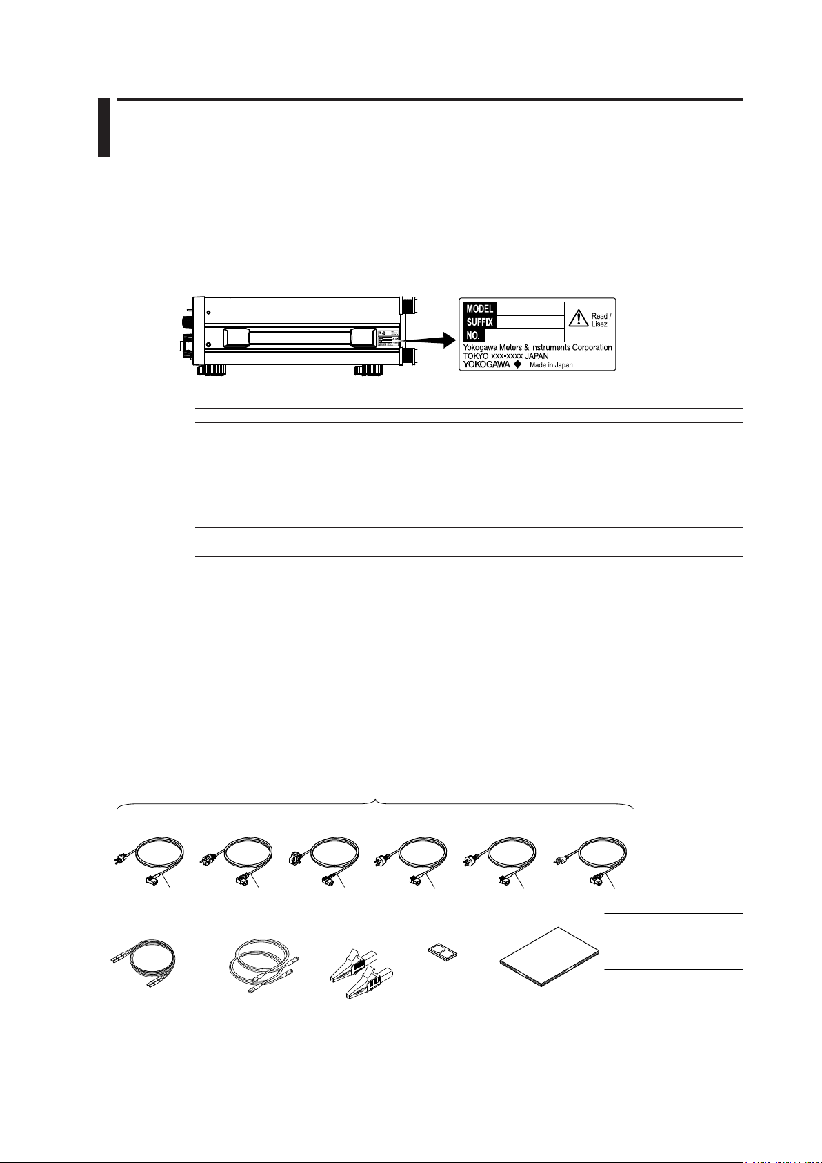
Checking the Contents of the Package
Measurement lead
set B8506ZK
Unpack the box and check the contents before operating the instrument. If the wrong items have been
delivered, if items are missing, or if there is a problem with the appearance of the items, contact your
nearest YOKOGAWA dealer.
2558A
Check that the product that you received is what you ordered by referring to the model name and suffix
code given on the name plate on the side panel.
MODEL and SUFFIX Codes
Model Suffix Code1Specifications
2558A 1200 V, 60 A
Power cord
Additional specifications
(options)
1 For products whose suffix code contains “Z,” an exclusive manual may be included. Please read
it along with the standard manual.
2 Make sure that the attached power cord meets the designated standards of the country and area
that you are using it in.
2
-D UL/CSA standard power cord, maximum rated voltage: 125 V
-F VDE standard power cord, maximum rating: 250 V
-R AS standard power cord, maximum rating: 250 V
-Q BS standard power cord, maximum rating: 250 V
-H GB standard power cord, maximum rating: 250 V
-N NBR standard power cord, maximum rating: 250 V
/C1 GP-IB interface
Standard Accessories
UL/CSA Standard
A1006WD
IM 2558A-01EN
No. (Instrument number)
When contacting the dealer from which you purchased the instrument, please give them the instrument
number.
The instrument is shipped with the following accessories. Make sure that all accessories are present
and undamaged.
Power cord (one cord that matches the suffix code is included)
VDE Standard
A1009WD
D F Q R
2
Measurement lead
set B8506WA
BS Standard
A1054WD
2
Alligator clip
adapter 2
set B8506ZL
AS Standard
A1024WD
Rubber leg cap
A9088ZM
GB Standard
A1064WD
1 Make sure that the attached power cord meets the designated standards of the country and area
that you are using it in.
2 The included measurement leads and alligator clip adapter set are exclusive to this product.
1
H
Manuals
NBR Standard
A1088WD
N
IM 2558A-01EN
User’s Manual (this manual)
IM 2558A-92Z1
Document for China
PIM 113-01Z2
List of worldwide contacts
iii
Page 6

Checking the Contents of the Package
Optional Accessories (Sold separately)
The following optional accessories are available for purchase separately.
For information about ordering accessories, contact your nearest YOKOGAWA dealer.
Item
Measurement lead 758917 1 set 1000 V CAT II Safety terminal cable with 2 leads (red and black)
Alligator clip adapter
(small)
Alligator clip adapter
(large)
Fork terminal adapter 758921 1 set 1000 V CAT II Safety terminal-to-fork terminal adapter. Red and
BNC cable 366924 1 — BNC-BNC. Length: 1 m. Rating: 42 V. —
Safety terminal adapter 758923 1 set 600 V CAT II Spring clamp type. Red and black, 1 pc. each.
Model/
Part No.
758933 1 set 1000 V CAT III Safety terminal cable with 2 leads (red and black)
B8506ZK 1 set 1500 V CAT I Safety terminal cable with 2 leads (red and black)
B8506WA 1 set — Current output cable with 2 leads (red and black)
758922 1 set 300 V CAT II Safety terminal-to-alligator clip adapter. Red and
758929 1 set 1000 V CAT II Safety terminal-to-alligator clip adapter. Red and
B8506ZL 1 set 1500 V CAT I Safety terminal-to-alligator clip adapter. Red and
366925 1 — BNC-BNC. Length: 2 m. Rating: 42 V. —
758931 1 set 1000 V CAT III Screw-in type. Red and black, 1 pc. each.
Min.
Q’ty
Safety
standard
Notes Manual No.
in a set. Length: 0.75 m. Rating: 1000 V, 32 A.
in a set. Length: 1 m. Rating: 1000 V, 19 A.
in a set. Length: 1 m. Rating: 1500 V, 19 A.
in a set. Length: 1.5 m. Rating: 42 V, 80 A.
black, 1 pc each. Rating: 300 V, 15 A.
black, 1 pc each. Rating: 1000 V, 32 A.
black, 1 pc each. Rating: 1500 V, 32 A.
black, 1 pc each. Rating: 1000 V, 20 A
Rating: 600 V, 10 A.
Rating: 1000 V, 36 A.
WARNING
—
—
—
—
—
—
—
—
—
—
• Use the accessories specied in this manual. Moreover, use the accessories of this product
only with Yokogawa products that specify them as accessories.
• Use the accessories of this product within the rated range of each accessory. When using
several accessories together, use them within the specification range of the accessory with
the lowest rating.
• Due to the structure of the product, it is possible to touch the metal parts of the fork terminal
adapter 758921. Be careful as this constitutes an electric shock hazard.
CAUTION
Use BNC cables 366924 and 366925 for the BNC I/O terminals.
French
AVERTISSEMENT
• Utiliser les accessoires spécifiés dans ce manuel. En outre, utiliser les accessoires de ce
produit uniquement avec des produits Yokogawa pour lesquels ils sont spécifiés comme
accessoires.
• Utilisez les accessoires de ce produit en fonction des valeurs nominales de chacun.
Lorsque vous employez plusieurs accessoires en même temps, utilisez les valeurs de
l’accessoire ayant les valeurs nominales les plus faibles.
iv
IM 2558A-01EN
Page 7

• Compte tenu de la structure du produit, il est possible de toucher les pièces métalliques de
l’adaptateur de borne à fourche 758921. Procédez avec soin, car cette opération présente
un risque de choc électrique.
ATTENTION
Utiliser les câbles BNC 366924 et 366925 pour les bornes E/S BNC.
Checking the Contents of the Package
IM 2558A-01EN
v
Page 8
Safety Precautions
This instrument is an IEC safety class I instrument (provided with a terminal for protective earth
grounding).
The general safety precautions described herein must be observed during all phases of operation.
If the instrument is used in a manner not specified in this manual, the protection provided by the
instrument may be impaired. YOKOGAWA assumes no liability for the customer’s failure to comply
with these requirements.
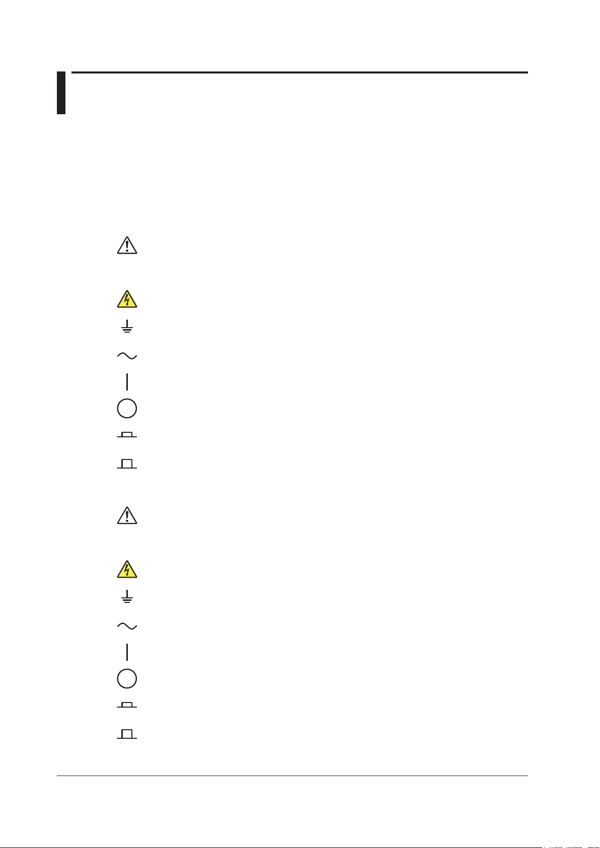
The following symbols are used on this instrument.
Warning: handle with care. Refer to the user’s manual or service manual. This symbol appears
on dangerous locations on the instrument which require special instructions for proper handling
or use. The same symbol appears in the corresponding place in the manual to identify those
instructions.
Electric shock, danger
Ground (earth) or functional ground terminal (do not use this terminal as a protective ground
terminal)
Alternating current
On (power)
Off (power)
Power-on state
Power-off state
French
Avertissement : À manipuler délicatement. Toujours se reporter aux manuels d’utilisation et
d’entretien. Ce symbole a été apposé aux endroits dangereux de l’instrument pour lesquels
des consignes spéciales d’utilisation ou de manipulation ont été émises. Le même symbole
apparaît à l’endroit correspondant du manuel pour identifier les consignes qui s’y rapportent.
Choc électrique, danger
Borne de terre ou borne de terre fonctionnelle (ne pas utiliser cette borne comme prise de
terre.)
Courant alternatif
Marche (alimentation)
Arrêt (alimentation)
Marche
Arrêt
vi
IM 2558A-01EN
Page 9

Safety Precautions
Failure to comply with the precautions below could lead to injury
or death or damage to the instrument.
WARNING
Use the Instrument Only for Its Intended Purpose
This instrument is an AC voltage and current standard that generates AC voltage and AC
current. Use this instrument only for this purpose.
Check the Physical Appearance
Do not use the instrument if there is a problem with its physical appearance.
Use the Correct Power Supply
Before connecting the power cord, ensure that the source voltage matches the rated supply
voltage of the 2558A and that it is within the maximum rated voltage of the provided power cord.
Use the Correct Power Cord and Plug
To prevent electric shock and fire, be sure to use a power cord provided by YOKOGAWA.
The main power plug must be plugged into an outlet with a protective earth terminal. Do not
invalidate this protection by using an extension cord without protective earth grounding.
Additionally, do not use the power cord supplied with this instrument with another instrument.
Connect the Protective Grounding Terminal
Make sure to connect the protective earth to prevent electric shock before turning on the
power. The power cord that comes with the instrument is a three-prong type power cord.
Connect the power cord to a properly grounded three-prong outlet.
Do Not Impair the Protective Grounding
Never cut off the internal or external protective earth wire or disconnect the wiring of the
protective earth terminal. Doing so may result in electric shock or damage to the instrument.
Do Not Use When the Protection Functions Are Defective
Before using this instrument, check that the protection functions, such as the protective
grounding and fuse, are working properly. If you suspect a defect, do not use the instrument.
Do Not Operate in an Explosive Atmosphere
Do not operate the instrument in the presence of flammable gasses or vapors. Doing so is
extremely dangerous.
Do Not Remove the Covers or Disassemble or Alter the Instrument
Only qualified YOKOGAWA personnel may remove the covers and disassemble or alter the
instrument. The inside of the instrument is dangerous because parts of it have high voltages.
Ground the Instrument before Making External Connections
Securely connect the protective grounding before connecting to the target device or to an
external control unit. Before touching the target device, turn off this instrument and check that
there is no voltage or current being generated.
Measurement Category
The measurement category of the 2558A terminals is Other (O). Do not use it for main power
supply circuits or circuits that fall under Measurement Categories II, III, and IV.
Install or Use the Instrument in Appropriate Locations
• Do not install the instrument outdoors or in locations subject to rain or water. Or, use the
instrument in such locations.
• Install the instrument so that you can immediately remove the power cord if an abnormal or
dangerous condition occurs.
IM 2558A-01EN
vii
Page 10

Safety Precautions
Be Careful When Generating High Voltage
• This product generates high voltage. Be careful of electric shock and electric discharge.
• To prevent electric shock, remove rings, watches, and other metallic accessories and
jewelry before operation.
Connect Cables Correctly
This instrument can generate large voltage and current. If you do not connect the devices
correctly, not only will it damage the instrument or the target device, it may also lead to electric
shock or fire. Be careful when you connect the cables, and be sure to check the following
points.
Before output (before turning on the output), check that:
• Cables have been connected to the instrument’s output terminals correctly.
Check that there are no voltage output cables that have been connected to the current
terminals.
Check that there are no current output cables that have been connected to the voltage
terminals.
• Cables have been connected to the target device correctly.
Check that there are no short circuits between voltage terminals or between the cables
connected to the voltage terminals.
• The cables are connected firmly to the current terminals.
• There no problems with the current terminals and the crimping terminals, such as the
presence of foreign substances.
During output (never touch the terminals or the connected cables when this instrument is on),
check that:
• There no problems with the current terminals and the crimping terminals, such as the
presence of foreign substances.
• The current terminals are not abnormally hot.
• The cables are connected firmly to the current terminals.
The terminal connections may become loose over time. If this happens, heat may be
generated due to changes in contact resistance. If you are going to take measurements
using the same setup for a long time, periodically check that the cables are firmly
connected to the terminals. Be sure to turn off both this instrument and the target device
before you check the connections.
After output (immediately after the output is turned off)
After you output a voltage or current, voltage may remain for some time even after you turn
the output off. This residual voltage may lead to electric shock. Do not touch the terminals
immediately after you turn the output off. The amount of time that voltage remains varies
depending on the target device.
CAUTION
Operating Environment Limitations
This product is a Class A (for industrial environment) product. Operation of this product in a
residential area may cause radio interference in which case the user will be required to correct
the interference.
viii
IM 2558A-01EN
Page 11

French
AVERTISSEMENT
Utiliser l’instrument aux seules fins pour lesquelles il est prévu
Cet instrument comprend une tension CA et courant standard. Il génère une tension CA et un
courant CA. Utilisez cet instrument à cette fin uniquement.
Inspecter l’apparence physique
Ne pas utiliser l’instrument si son intégrité physique semble être compromise.
Use the Correct Power Supply
Avant de brancher le cordon d’alimentation, vérifier que la tension source correspond à la
tension d’alimentation nominale du 2558Aet qu’elle est compatible avec la tension nominale
maximale du cordon d’alimentation.
Utiliser le cordon d’alimentation et la fiche adaptés
Pour éviter les risques de choc électrique ou d’incendie, utilisez le cordon d’alimentation fourni
par YOKOGAWA. La fiche doit être branchée sur une prise secteur raccordée à la terre. En
cas d’utilisation d’une rallonge, celle-ci doit être impérativement reliée à la terre. Par ailleurs,
n’utilisez pas le cordon d'alimentation fourni pour cet instrument avec un autre appareil.
Brancher la prise de terre
Avant de mettre l’instrument sous tension, penser à brancher la prise de terre pour éviter tout
choc électrique. Le cordon d’alimentation livré avec l’instrument est doté de trois broches.
Brancher le cordon d’alimentation sur une prise de courant à trois plots et mise à la terre.
Safety Precautions
Ne pas entraver la mise à la terre de protection
Ne jamais neutraliser le fil de terre interne ou externe, ni débrancher la borne de mise à la
terre. Cela pourrait entraîner un choc électrique ou endommager l’instrument.
Ne pas utiliser lorsque les fonctions de protection sont défectueuses
Avant d’utiliser l'instrument, vérifier que les fonctions de protection, telles que le raccordement
à la terre et le fusible, fonctionnent correctement. En cas de dysfonctionnement possible, ne
pas utiliser l’instrument.
Ne pas utiliser dans un environnement explosif
Ne pas utiliser l’instrument en présence de gaz ou de vapeurs inflammables. Cela pourrait
être extrêmement dangereux.
Ne pas retirer le capot, ni démonter ou modifier l’instrument
Seul le personnel YOKOGAWA qualifié est habilité à retirer le capot et à démonter ou modifier
l’instrument. Certains composants à l’intérieur de l'instrument sont à haute tension et par
conséquent, représentent un danger.
Relier l’instrument à la terre avant de le brancher sur des connexions externes
Connectez le conducteur de terre avant de raccorder le dispositif cible ou une unité de
commande externe. Avant de toucher le dispositif cible, mettez l’instrument hors tension, et
vérifiez qu’aucune tension ni aucun courant ne sont émis.
Catégorie de mesure
La catégorie de mesure des bornes 2558A est O (Other, Autre). Ne l'utilisez pas pour les
circuits d'alimentation principale ou ceux correspondant aux catégories de mesure II, III et IV.
IM 2558A-01EN
Installer et utiliser l’instrument aux emplacements appropriés
• Ne pas installer, ni utiliser l'instrument à l’extérieur ou dans des lieux exposés à la pluie ou
à l’eau.
• Installer l’instrument de manière à pourvoir immédiatement le débrancher du secteur en
cas de fonctionnement anormal ou dangereux.
ix
Page 12

Safety Precautions
Manipulez avec précaution lors de la génération de tension élevée
• Le produit génère une tension élevée. Faites attention au choc électrique et à la décharge
électrique.
• Afin d'éviter tout choc électrique, retirer les bagues, les montres et autres accessoires
métalliques ainsi que les bijoux avant la mise en service.
Câblage correct
Cet équipement délivre une tension et une intensité élevées. Si vous ne raccordez pas
correctement les appareils, non seulement cela risque d’endommager l’équipement ou
l’appareil cible, mais en plus cela risque d’entraîner un choc électrique ou un incendie.
Branchez toujours les câbles en plomb correctement et vérifiez les points suivants.
Avant le sortie (avant la mise sous tension), vérifier que :
• Les câbles en plomb sont correctement raccordés aux bornes de sortie de l’équipement.
Les câbles de sortie de la tension n'ont pas été malencontreusement branchés sur les
bornes de courant.
Les câbles de sortie du courant n'ont pas été malencontreusement branchés sur les bornes
de tension.
• Les câbles ont été correctement branchés sur l’appareil voulu.
Vérifier qu’il n’y a pas de court-circuit entre les bornes de tension ou entre les câbles
raccordés aux bornes de tension.
• Les câbles ont été correctement branchés sur les bornes de courant.
• Il n’y a aucun problème avec les bornes d'entrée de courant et les bornes de sertissage,
comme par exemple une présence de corps étrangers.
Pendant la sortie (ne pas toucher les bornes ni les câbles branchés lorsque l’instrument est
sous tension), vérifier que :
• Il n’y a aucun problème avec les bornes d’entrée de courant et les bornes de sertissage,
comme par exemple une présence de corps étrangers.
• Les bornes d’entrée ne chauffent pas anormalement.
• Les câbles ont été correctement branchés sur les bornes de courant.
Les raccordements de bornes risquent de se détacher dans le temps. Le cas échéant,
une chaleur peut être générée suite aux changements de résistance au contact. Vérifiez
régulièrement que les câbles en plomb sont bien raccordés aux bornes. Éteignez bien à la
fois cet équipement et l’appareil cible avant de vérifier les raccordements.
Après la sortie (tout de suite après la mise hors tension)
Une fois une tension ou un courant obtenu(e), la tension peut rester un certain temps,
même après la mise hors tension. Cette tension résiduelle peut entraîner un choc
électrique. Ne touchez pas immédiatement les bornes après la mise hors tension. La durée
pendant laquelle le tension reste varie en fonction de l’appareil cible.
ATTENTION
Limitations relatives à l’environnement opérationnel
Ce produit est un produit de classe A (pour environnements industriels). L’utilisation de ce
produit dans un zone résidentielle peut entraîner une interférence radio que l’utilisateur sera
tenu de rectifier.
x
IM 2558A-01EN
Page 13

Sales in Each Country or Region
Waste Electrical and Electronic Equipment
Waste Electrical and Electronic Equipment (WEEE), Directive
(This directive is valid only in the EU.)
This product complies with the WEEE directive marking requirement. This marking indicates
that you must not discard this electrical/electronic product in domestic household waste.
Product Category
With reference to the equipment types in the WEEE directive, this product is classified as a
“Monitoring and control instruments” product.
When disposing products in the EU, contact your local Yokogawa Europe B.V. office.
Do not dispose in domestic household waste.
Authorized Representative in the EEA
Yokogawa Europe B.V. is the authorized representative of Yokogawa Meters & Instruments
Corporation for this product in the EEA. To contact Yokogawa Europe B.V., see the separate list of
worldwide contacts, PIM 113-01Z2.
IM 2558A-01EN
xi
Page 14

Conventions Used in This Manual
Notes
The notes and cautions in this manual are categorized using the following symbols.
Improper handling or use can lead to injury to the user or damage to the
instrument. This symbol appears on the instrument to indicate that the user must
refer to the user’s manual for special instructions. The same symbol appears in
the corresponding place in the user’s manual to identify those instructions. In the
user’s manual, the symbol is used in conjunction with the word “WARNING” or
“CAUTION.”
WARNING
CAUTION
Calls attention to actions or conditions that could cause serious or fatal injury to
the user, and precautions that can be taken to prevent such occurrences.
Calls attention to actions or conditions that could cause light injury to the user
or cause damage to the instrument or user’s data, and precautions that can be
taken to prevent such occurrences.
French
AVERTISSEMENT
ATTENTION
Calls attention to information that is important for the proper operation of the
Note
Attire l’attention sur des gestes ou des conditions susceptibles
Attire l’attention sur des gestes ou des conditions susceptibles
de provoquer des blessures graves (voire mortelles), et sur les
précautions de sécurité pouvant prévenir de tels accidents.
deprovoquer des blessures légères ou d’endommager l’instrument
ou lesdonnées de l’utilisateur, et sur les précautions de sécurité
susceptiblesde prévenir de tels accidents.
instrument.
Characters That Appear on the 7-Segment LED
Because this instrument uses a 7-segment LED display, numbers, letters, and mathematical symbols
are displayed using special characters. For details, see section 1.3, “Digital Numbers and Characters.”
xii
IM 2558A-01EN
Page 15

Conventions Used in This Manual
Symbols and Conventions Used in Procedural Explanations
The contents of the procedural explanations are indicated using the following symbols.
Procedure
Explanation
Carry out the procedure according to the step numbers. All procedures are
written under the assumption that you are starting operation at the beginning
of the procedure, so you may not need to carry out all the steps in a procedure
when you are changing the settings.
This section describes the setup items and the limitations regarding the
procedures. It may not give a detailed explanation of the feature. For a detailed
explanation of the feature, see chapter 2.
<<Command Mnemonic>>
Indicates a communication command that corresponds to some of the features described on the
procedural explanation page.
Characters and Terminology Used in Procedural Explanations
Dial and Switches
Bold characters used in the procedural explanations indicate dials and switches on the panel.
IM 2558A-01EN
xiii
Page 16

Contents
List of Manuals ...................................................................................................................................i
Checking the Contents of the Package............................................................................................ iii
Safety Precautions ........................................................................................................................... vi
Sales in Each Country or Region ..................................................................................................... xi
Conventions Used in This Manual .................................................................................................. xii
Chapter 1 Component Names and Functions
1.1 Panel ................................................................................................................................ 1-1
1.2 Dial and Switches ............................................................................................................. 1-3
1.3 Digital Numbers and Characters ...................................................................................... 1-6
Chapter 2 Features
2.1 System Configuration ....................................................................................................... 2-1
2.2 Output ............................................................................................................................... 2-2
2.3 Output Divider .................................................................................................................. 2-4
2.4 Deviation and Presets ...................................................................................................... 2-5
2.5 Sweeping .......................................................................................................................... 2-7
2.6 Synchronous Operation .................................................................................................... 2-8
2.7 Other Features ................................................................................................................. 2-9
Chapter 3 Preparation
3.1 Handling Precautions ....................................................................................................... 3-1
3.2 Installing the Instrument ................................................................................................... 3-3
3.3 Connecting to the Power Supply ...................................................................................... 3-6
3.4 Turning On and Off the Power Switch .............................................................................. 3-8
3.5 Wiring Precautions ......................................................................................................... 3-10
3.6 Connecting Cables ......................................................................................................... 3-14
Chapter 4 How to Use the SETUP Menu
4.1 SETUP Menu Tree Structure ............................................................................................ 4-1
4.2 SETUP Menu and Dial Assignments ................................................................................ 4-3
4.3 Entering and Displaying Values ........................................................................................ 4-4
Chapter 5 Voltage and Current Generation
5.1 Selecting Whether to Ground the LO Terminal (COMMON Terminal) .............................. 5-1
5.2 Setting the Frequency ...................................................................................................... 5-3
5.3 Selecting the Voltage or Current Range ........................................................................... 5-6
5.4 Main Voltage and Current Settings ................................................................................... 5-7
5.5 Dividing the Output ........................................................................................................... 5-8
5.6 Turning the Output On and Off ......................................................................................... 5-9
5.7 Finely Adjusting the Output (Deviation and Preset) .........................................................5-11
5.8 Sweeping ........................................................................................................................ 5-13
xiv
IM 2558A-01EN
Page 17

Contents
Chapter 6 Calibrating the Frequency Meter
6.1 Selecting Whether to Ground the LO Terminal (COMMON Terminal) .............................. 6-1
6.2 Setting the Frequency ...................................................................................................... 6-3
6.3 Selecting the Voltage or Current Range ........................................................................... 6-4
6.4 Main Voltage and Current Settings ................................................................................... 6-5
6.5 Dividing the Output ........................................................................................................... 6-6
6.6 Turning the Output On and Off ......................................................................................... 6-7
6.7 Finely Adjusting the Output (Deviation and Preset) .......................................................... 6-9
6.8 Sweeping .........................................................................................................................6-11
Chapter 7 Synchronous Operation
7.1 External Signal Input and Internal Signal Output ............................................................. 7-1
7.2 Synchronous Operation .................................................................................................... 7-3
Chapter 8 Other Features
8.1 Turning the Beep Sound On and Off ................................................................................ 8-1
8.2 Error Log Display .............................................................................................................. 8-2
8.3 Initializing the Settings ...................................................................................................... 8-4
8.4 Displaying the Product Information .................................................................................. 8-5
Chapter 9 USB Interface
9.1 USB Interface Features and Specifications ...................................................................... 9-1
9.2 Connecting to the USB Interface ...................................................................................... 9-2
1
2
3
4
5
6
7
8
Chapter 10 Ethernet Interface
10.1 Ethernet Interface Features and Specifications ............................................................. 10-1
10.2 Connecting to the Ethernet Interface .............................................................................. 10-2
10.3 Configuring the 2558A Ethernet Settings ....................................................................... 10-3
Chapter 11 GP-IB Option
11.1 GP-IB Interface Features and Specifications ..................................................................11-1
11.2 Connecting to the GP-IB Interface ..................................................................................11-3
11.3 Configuring the 2558A GP-IB Settings ............................................................................11-5
11.4 Responses to Interface Messages ..................................................................................11-7
Chapter 12 Programming Overview
12.1 Messages ....................................................................................................................... 12-1
12.2 Commands ..................................................................................................................... 12-3
12.3 Responses ..................................................................................................................... 12-5
12.4 Data ................................................................................................................................ 12-6
12.5 Synchronization with the Controller ................................................................................ 12-8
9
10
11
12
13
14
15
16
IM 2558A-01EN
App
Index
xv
Page 18

Contents
Chapter 13 Commands
13.1 List of Commands .......................................................................................................... 13-1
13.2 COMMunicate Group ..................................................................................................... 13-3
13.3 DIVider Group................................................................................................................. 13-4
13.4 FREQuency Group ......................................................................................................... 13-5
13.5 OUTPut Group ............................................................................................................... 13-6
13.6 DEViation Group............................................................................................................. 13-7
13.7 SOURce Group .............................................................................................................. 13-8
13.8 STATus Group ................................................................................................................ 13-9
13.9 SWEep Group .............................................................................................................. 13-10
13.10 SYSTem Group .............................................................................................................13-11
13.11 Common Command Group .......................................................................................... 13-13
Chapter 14 Status Reports
14.1 About Status Reports ..................................................................................................... 14-1
14.2 Status Byte ..................................................................................................................... 14-3
14.3 Standard Event Register ................................................................................................ 14-4
14.4 Extended Event Register ................................................................................................ 14-5
14.5 Output and Error Queues ............................................................................................... 14-6
Chapter 15 Troubleshooting, Maintenance, and Inspection
15.1 Troubleshooting .............................................................................................................. 15-1
15.2 Error Code Descriptions and Corrective Actions ............................................................ 15-2
15.3 Communication Error Messages .................................................................................... 15-3
15.4 Instrument Error Detection and Clearance ..................................................................... 15-7
15.5 Self-test .......................................................................................................................... 15-8
15.6 Cleaning the Filter .......................................................................................................... 15-9
15.7 Recommended Part Replacement ................................................................................15-11
15.8 Adjustment and Calibration ...........................................................................................15-11
Chapter 16 Specifications
16.1 Output ............................................................................................................................. 16-1
16.2 Accuracy ......................................................................................................................... 16-2
16.3 Functions ........................................................................................................................ 16-4
16.4 External Input and Output .............................................................................................. 16-5
16.5 Computer Interface ......................................................................................................... 16-5
16.6 General Specifications ................................................................................................... 16-6
16.7 External Dimensions ...................................................................................................... 16-8
Appendix
Appendix 1 Block Diagram .................................................................................................... App-1
Appendix 2 Example of Using the 2558A to Calibrate an Analog Meter ............................... App-2
Appendix 3 Example of Using the 2558A to Calibrate a Power Meter ..................................App-4
Appendix 4 Phase Shift Feature ...........................................................................................App-5
Appendix 5 Factory Default Settings ..................................................................................... App-6
Appendix 6 About the IEEE 488.2-1992 Standard ................................................................ App-7
Index
xvi
IM 2558A-01EN
Page 19

→ Sections 1.2, 5.8, and 6.8
DEVIATION/PRESET section
Chapter 1 Component Names and Functions
1.1 Panel
Front Panel
FREQUENCY/PHASE section
Sets and displays the frequency or phase angle
→ Sections 1.2, 5.2, and 6.2
Main setting section
Sets and displays the voltage or current level.
→ Sections 1.2, 5.4, and 6.4
1
Component Names and Functions
Finely adjusts the output value
→ Sections 1.2, 5.7, and 6.7
REMOTE indicator
Illuminates when the 2558A is in remote
mode (controlled through communications)
→ Sections 9.1, 10.1, and 11.1
OUTPUT indicator
Displays the voltage, current, or frequency.
→ Sections 5.6 and 6.6
Output unit indicator
Displays the output unit.
RANGE dial
Switches the voltage or
current range
→ Section 5.3 and 6.3
FREQUENCY dial
Switches the frequency
→ Sections 5.2 and 6.2
OUTPUT DIVIDER section
Divides the voltage or current
level or the frequency output
→ Sections 5.5 and 6.5
Power switch
Turns the output on and off
→ Section 3.4
HIGH VOLTAGE indicator
Illuminates when the RANGE dial
is set to 300 V or 1000 V
→ Section 5.3 and 6.3
Voltage terminals
Used to connect the included
measurement leads
→ Section 3.6
Current terminals
Used to connect the included
measurement leads
→ Section 3.6
LO TO EARTH indicator
Indicates the grounding state of the LO terminal.
Illuminates when SETUP EARTH is on
→ Section 5.1, and 6.1
OUTPUT section
Turns the voltage or current output on and off
→ Sections 1.2, 5.6 and 6.6
Switches remote mode (controlled through
communications) to local mode
→ Sections 9.1, 10.1, and 11.1
SWEEP section
Performs up or down sweeps
IM 2558A-01EN
1-1
Page 20

GP-IB connector (option)
Top panel Bottom panel
1.1 Front Panel, Rear Panel, and Top Panel
Rear Panel
Inlet holes
→ Section 3.2
Used to control the 2558A from a PC
→ Section 11.2
Ethernet port
Used to connect the 2558A to a network
(10BASE-T/100BASE-TX)
→ Section 10.2
USB port
Used to connect the 2558A to a PC that has a
USB interface and to control the 2558A with
USB-TMC commands
→ Section 9.2
External signal input terminal
Used to generate voltage or current on the
basis of an external oscillator frequency or
synchronize multiple 2558As
→ Section 7.1 and 7.2
Signal output terminals
Used to synchronize multiple 2558As
→ Sections 7.1 and 7.2
Top and Bottom Panels
Power inlet
Connect the power cord.
→ Section 3.3
1-2
Outlet holes
→ Section 3.2
IM 2558A-01EN
Page 21

1.2 Dial and Switches
FREQUENCY/PHASE display
Main setting display
FREQUENCY/PHASE Section
The FREQUENCY/PHASE section consists of a cursor switch (◄►), a VARIABLE dial, a 6-digit
FREQUENCY/PHASE display, and a unit indicator. These controls work differently depending on the
FREQUENCY dial setting.
Displays the set frequency, set phase angle, or measured frequency.
The following setting values or measured values are displayed
depending on the FREQUENCY dial.
• When set to 50, 60, or 400: The fixed frequency
• When set to VAR: Arbitrary frequency
• When set to EXT1: External oscillator frequency
• When set to EXT2 (PHASE): Phase angle
• FREQUENCY METER MIN: Minimum frequency
• FREQUENCY METER MAX: Maximum frequency
Unit indicator
Indicates the phase angle or frequency unit
• Phase angle: °
• Frequency: Hz
VARIABLE dial
Set the number of the selected digit in the range of 0 to 9.
Within the selectable range of frequencies or phase angles, carrying over
and borrowing occurs automatically. If the upper or lower limit of the range
is reached, turning the dial further will not change the number of the digit.
This dial is valid when the FREQUENCY dial is set to one of the following:
VAR, EXT2(PHASE), MIN/MAX(FREQUENCY METER)
1
Component Names and Functions
Cursor switch
Selects the digit that you want to set. The number of the selected digit blinks. Flip the
switch to the left to select the next left digit. Flip the switch to the right to select the
next right digit. If the highest digit is selected, flipping the switch to the left will select
the lowest digit. If the lowest digit is selected, flipping the switch to the right will select
the highest digit. You can use this switch when the VARIABLE dial is valid.
Main Setting Section
The main setting section consists of four main setting dials, a 5-digit main setting display, and a unit
indicator. The decimal place varies depending on the RANGE dial setting.
Displays the voltage or current level. The
number of displayed digits varies depending on
the voltage or current range.
Main setting dials
Set the number of each digit on the main setting display in the range of 0 to 9.
Carrying over and borrowing occurs automatically up to 120% of the voltage
or current range. If the upper or lower limit of the range is reached, turning the
dial further will not change the number of the digit.
Unit indicator
Displays the voltage or current unit.
• Voltage: mV, V
• Current: mA, A
IM 2558A-01EN
1-3
Page 22

DEVIATION display
UP indicator
Illuminates when sweeping up
ON indicator
Illuminates when voltage or current is being generated
1.2 Dial and Switches
DEVIATION/PRESET Section
The DEVIATION/PRESET section consists of two deviation dials, a 4-digit DEVIATION display, a
PRESET switch, and a preset indicator.
Deviation dial 1
Sets the tenths digit of the deviation value display
The deviation dial sets the number of each digit in the range of 0 to 9. Dial 1 changes the number in
increments of 2; Dial 2 changes the number in increments of 1. Carrying over and borrowing occurs
automatically up to ±20%. If the upper or lower limit of the range is reached, turning the dial further will
not change the number.
Displays the deviation in reference to the main setting
Preset value indicator
Displays the deviation value set with the PRESET switch
PRESET switch
Set the deviation in reference to the main setting.
Deviation dial 2
Sets the hundredths digit of the deviation value display. You can turn this dial with less torque.
SWEEP Section
The SWEEP section consists of a SWEEP switch and a pair of UP and DOWN indicators for indicating
the sweep direction.
DOWN indicator
Illuminates when sweeping down
SWEEP switch
UP sweep
Flip the switch up to sweep up. Flipping the switch down
while sweeping up stops the sweeping (HOLD state).
DOWN sweep
Flip the switch down to sweep down. Flipping the switch up
while sweeping down stops the sweeping (HOLD state).
OUTPUT Section
The OUTPUT section consists of a OUTPUT switch and a pair of ON and OFF indicators.
OFF indicator
Illuminates when voltage or current is not being generated
OUTPUT switch
Local mode
Flip up to turn the output on.
Flip down to turn the output off.
Flipping this switch down in remote mode (controlled through
communications) causes the 2558A to switch to local mode.
1-4
IM 2558A-01EN
Page 23

n display
1.2 Dial and Switches
OUTPUT DIVIDER Section
The OUTPUT DIVIDER section consists of m and n dials for setting the divider value (n/m) and m and
1
Component Names and Functions
n displays to show the value.
Indicates the numerator of the divider value
n dial
Sets the numerator, n, of the divider value. The range is 0 to m.
m dial
Sets the denominator, m, of the divider value. The range is 4 to 15.
Turning the m dial resets numerator n to the denominator m value.
m display
Indicates the denominator of the divider value
IM 2558A-01EN
1-5
Page 24

1.3 Digital Numbers and Characters
Because this instrument uses a 7-segment LED display, numbers, letters, and mathematical symbols
are displayed using special characters in the manner shown below. Some of the characters shown
below are not used by this instrument.
lowercase
lowercase
power
1-6
IM 2558A-01EN
Page 25

1
Chapter 2 Features
2.1 System Configuration
PC
2
Features
Communication interface
Command control
)
USB-TMC
(
GP-IB
USB
)
VXI-11
(
Ether
2558A
EXT OSC
EXT1, EXT2 (I(cos))
EXT2 (Q(sin))
VOLTAGE
OUTPUT
Hi Lo
DUT (output target)
CURRENT
OUTPUT
Hi
Lo
I(cos)
Q(sin)
2558A
Slave
IM 2558A-01EN
2-1
Page 26
2.2 Output
Current
2 At 1% to 120% of the range
60 A 12 A 1.2 A
Voltage
CAUTION
When voltage or current is being generated, if a load that would cause the range generated
indicated below to be exceeded is connected, the instrument will detect the abnormal load
and turn off the output.
French
ATTENTION
Lors de la génération de la tension ou du courant, si la charge appliquée risque de sortir de
la plage générée indiquée ci-dessous, l’instrument détecte une charge anormale et coupe la
sortie.
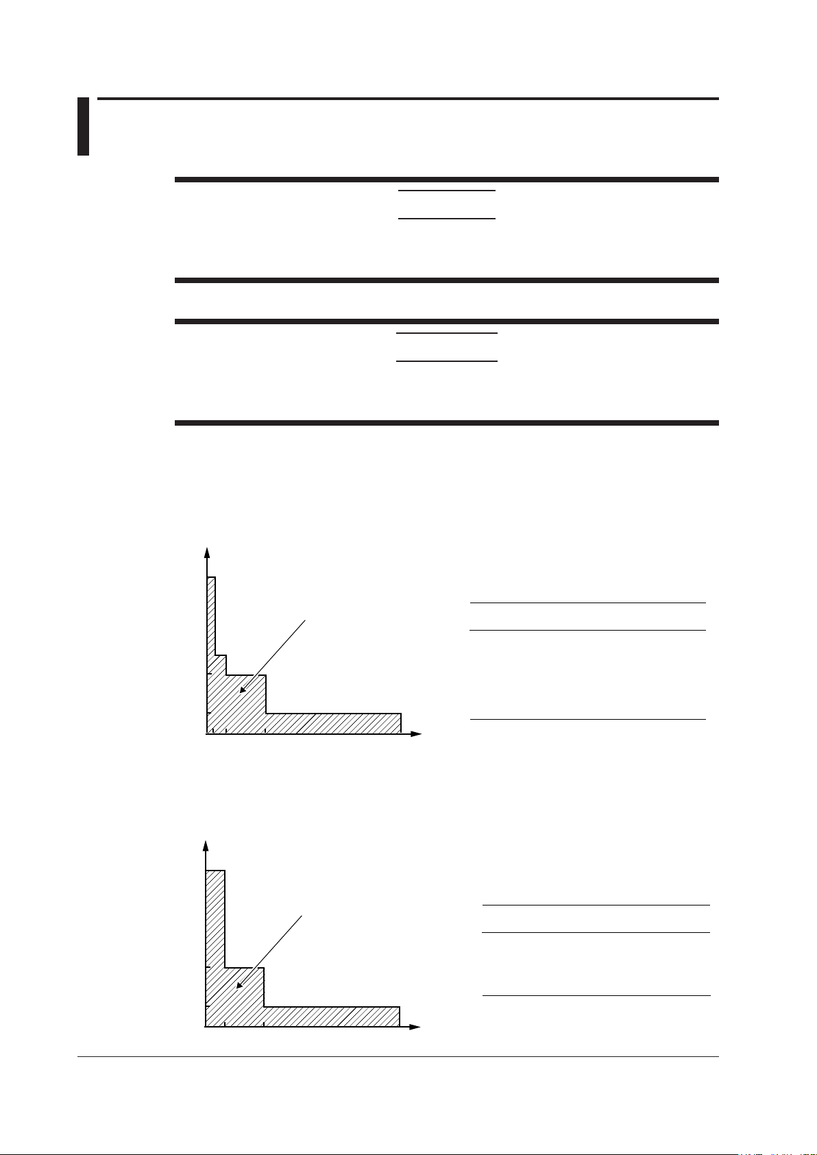
Voltage Range and Range Generated
The maximum output at each voltage range is shown in the figure below. The maximum output
is 120% of each voltage range rating. If you set the voltage range to 300 V or 1000 V, the HIGH
VOLTAGE indicator will illuminate. If you set the voltage to 150 V or higher, a high-voltage caution
beep will sound.
3 A
Range generated
0.3 A
0.1 A
6 mA
Voltage
1200 V 360 V 120 V 12 V
Voltage
Range
100 mV 0 mV to 120.00 mV —
1 V 0 V to 1.2000 V 0.5 A or higher
10 V 0 V to 12.000V approx. 3 A
100V 0 V to 120.00 V approx. 0.3 A
300 V 0 V to 360.0 V approx. 0.1 A
1000 V 0 V to 1200.0 V approx. 6 mA
1 Generates 144% of the range when used
with deviation (–20%)
Range
Generated
1
Maximum
2
Output
Current Range and Range Generated
The maximum output at each current range is shown in the figure below. The maximum output is 120%
of each current range rating.
15 V
Range generated
3 V
0.6 V
Current
Current
Range
100 mA 0 mA to 120.00 mA approx. 15 V
1 A 0 A to 1.2000 A approx. 15 V
10 A 0 A to 12.000 A approx. 3 V
50 A 0 A to 120.00 A approx. 0.6 V
1 Generates 144% of the range when used
with deviation (–20%)
2 At 1% to 120% of the range
Range
Generated
1
Maximum
2
Output
2-2
IM 2558A-01EN
Page 27

1
2.2 Output
Turning the Output On and Off
There are two output modes: OFF and ON.
OFF: The output is disconnected. The specified output level is not generated.
ON: The output is connected, and the specified output level is generated. During output, the output
display shows the voltage or current.
Frequency and Phase Angle
Fixed Frequency (50 Hz, 60 Hz, or 400 Hz)
The 2558A uses its internal oscillator to output sinusoidal voltage or current. 50 Hz and 60 Hz are
used for devices that receive power line signals. 400 Hz is mainly used for meters used in aircrafts
and marine vessels.
Specific Frequency (VAR)
The 2558A uses its internal variable oscillator to output sinusoidal voltage or current. You can
specify a frequency of your choice using a dial on the front panel. The setting is shown on the front
panel. The accuracy is the same if you set one of the fixed frequencies with this feature.
Selectable range: 40 Hz to 1000 Hz
External Oscillator EXT1
To output voltage or current, connect an external oscillator to the I side (EXT1) of the 2558A’s
external signal input terminal. Use this feature when you need to synchronize with other signals
(i.e., function generator). The phase between input and output is reversed in order to accommodate
compatibility with the predecessor model, 2558. The 2558A measures the external oscillator
frequency and shows it on the front panel.
Input range: 40 Hz to 1000 Hz
2
Features
External Oscillator EXT2 (PHASE)
To output voltage or current, connect the two signal outputs from another 2558A. Use this feature to
perform synchronous operation between multiple 2558As. You can set the phase angle according to
the measurement system. The setting is shown on the front panel.
Selectable range: –180.000° to +359.999°
Input range: 40 Hz to 1000 Hz. The frequency is not shown on the front panel.
IM 2558A-01EN
2-3
Page 28
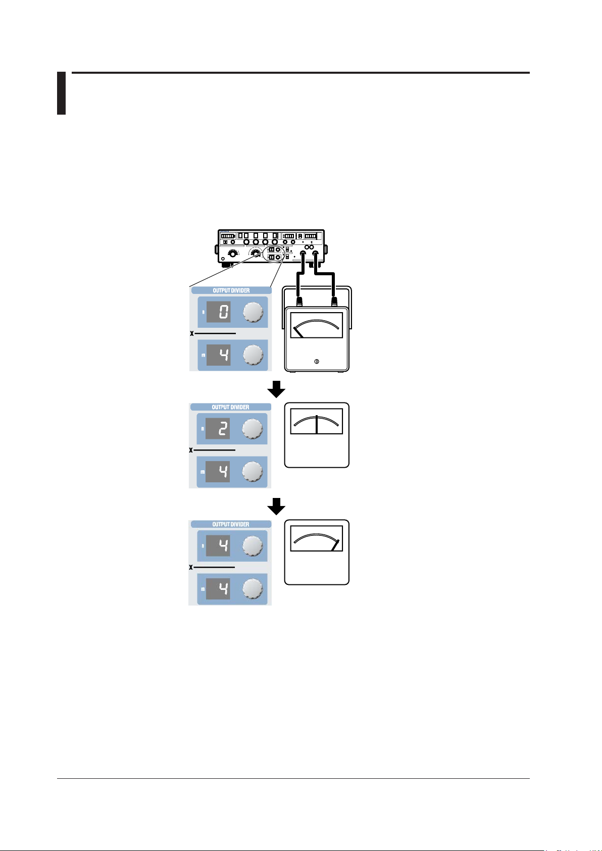
2.3 Output Divider
Main setting = 10 A
n = 0
m = 4
Ammeter
When calibrating the target meter, the output divider feature divides the voltage or current level or the
frequency into as many points as you need to calibrate. You can set the main setting to the maximum
indication on the target meter, and vary the divider value to calibrate the various points on the meter.
Divider value range: n/m where n = 0 to m and m = 4 to 15
Setup example: When the main setting is 10 A, n is 2, and m is 4,
output value = 10 A×2/4 = 5 A (divider value: 1/2)
Ammeter
0 A
Frequency Output Divider
If the frequency is set to FREQUENCY METER MIN or FREQUENCY METER MAX, the oscillation
frequency is divided and output. The main setting is not divided.
For example, if the MIN frequency is 45 Hz, the MAX frequency is 65 Hz, and the main setting is 100 V,
the following result is obtained.
At n =0 and m = 4, the output voltage is 100 V, and the frequency meter shows 45 Hz.
At n =2 and m = 4, the output voltage is 100 V, and the frequency meter shows 55Hz.
At n =4 and m = 4, the output voltage is 100 V, and the frequency meter shows 65Hz.
In this example, the frequency width of 20 Hz is divided into four parts and output at 5 Hz intervals.
The voltage level is not divided.
n = 2
m = 4
n = 4
m = 4
5 A
Ammeter
10 A
2-4
IM 2558A-01EN
Page 29
1
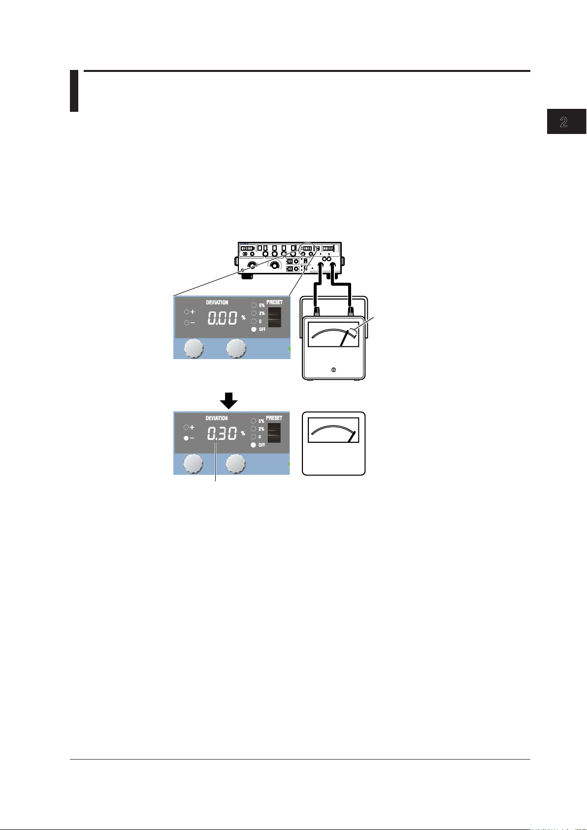
2.4 Deviation and Presets
Main setting = 10 A
Error (deviation)
Use the deviation dial to align
the meter needle to the accurate
scale position.
The deviation is –0.30%.
Deviation
This feature is used to check the relative error (deviation) of the meter scale calibration. If the meter
needle is not pointing accurately to the appropriate scale mark, you can turn a deviation dial on the
front panel to finely adjust the voltage or current output level or the frequency so that the needle points
accurately to the mark. The amount of fine adjustment is displayed as the deviation.
Deviation setting range: ±20.00%
Setup example: Main setting = 10 A, divider value n/m = 1
2
Features
Ammeter
9.97 A
Ammeter
10 A
In the example above, before fine adjustment, the meter needle is pointing to 9.97 A, which is 0.30%
smaller than the 10 A current output from the 2558A. The deviation polarity (the sign) of the 2558A
indicates whether the target device indication is larger or smaller than the accurate position. In this
example, because the meter is pointing to a value that is 0.30% smaller than the 2558A output value,
the 2558A displays –0.30%.
Deviation at Each Calibration Point
When the deviation feature is used in conjunction with the output divider feature explained in section
2.3, you can check at each calibration point the deviation in reference to the maximum scale value.
Note that if the frequency is set to FREQUENCY METER MIN or FREQUENCY METER MAX, the
deviation is in reference to the span.
When the maximum scale value is 10 A, 1% is 0.1 A.
If you are using the output divider feature at n = 2 and m = 10, when 2 A is being output, 1% will
also be 0.1 A.
IM 2558A-01EN
2-5
Page 30
short of the calibration point
Example when calibrating
in increasing order
2.4 Deviation and Presets
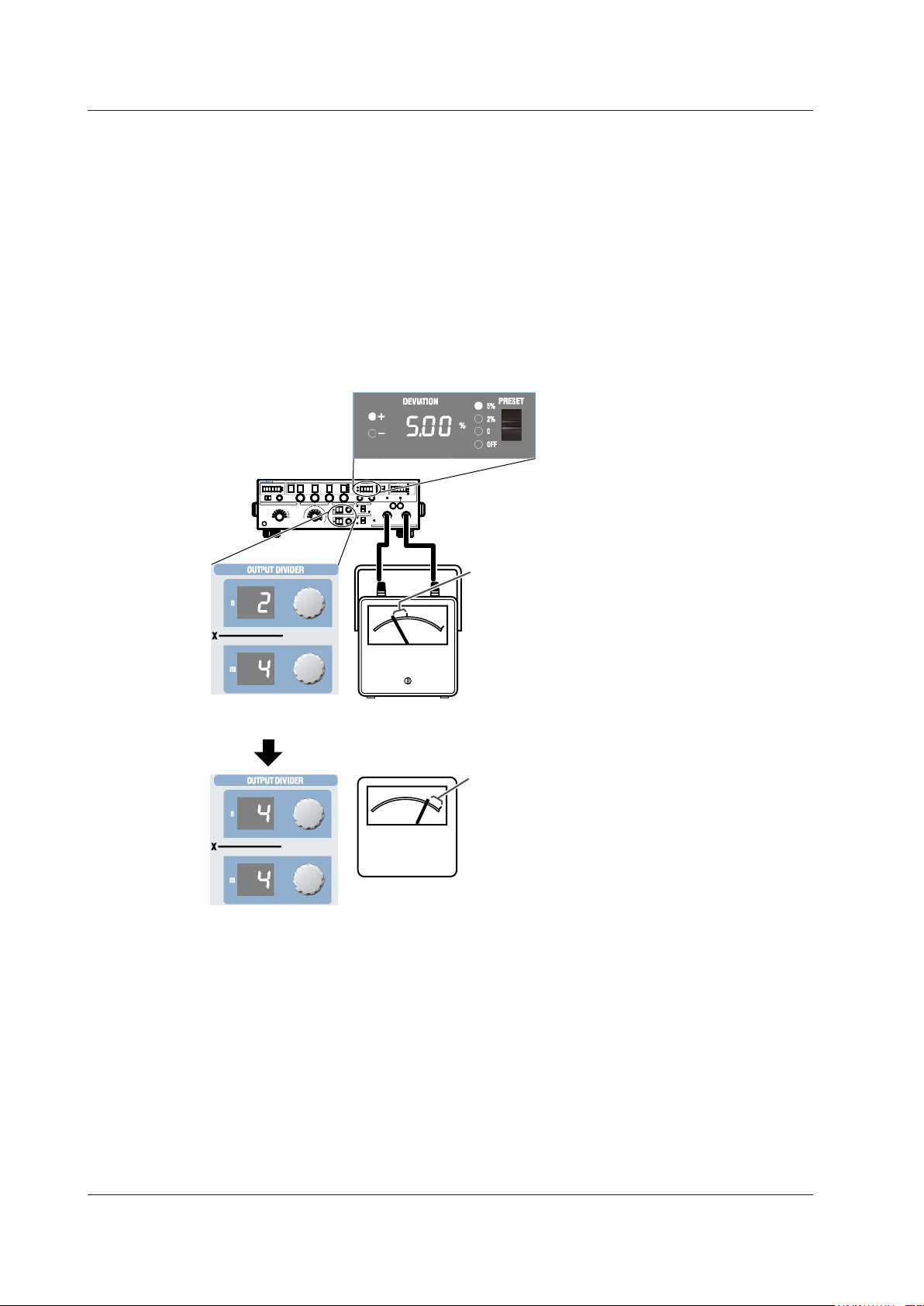
Presets
Deviation presets can be used to make the meter indicate values that are short of the accurate scale
positions when you change the output divider setting.
You can use this feature to calibrate a meter when using the output divider feature to calibrate the
points in increasing or decreasing order.
5%: When calibrating in increasing order, the deviation is set to +5.00%.
When calibrating in decreasing order, the deviation is set to –5.00%.
2%: When calibrating in increasing order, the deviation is set to +2.00%.
When calibrating in decreasing order, the deviation is set to –2.00%.
0%: The deviation is cleared when the divider value is changed.
OFF: The specified deviation is retained even when the divider value is changed.
Main setting = 10 A
Preset (5%)
Indicates a point that is
by the preset amount
Ammeter
4.5 A
Use the n dial to move
the meter needle up.
Indicates a point that is
short of the calibration point
by the preset amount
Ammeter
9.5 A
In the above example, the 2558A is generating –5.00% of the output setting. To calibrate the scale,
turn a deviation dial to move the meter needle to the correct position. For details on how to read the
deviation, see “Deviation” on the previous page.
2-6
IM 2558A-01EN
Page 31

1
2.5 Sweeping
Main setting = 10 A
Sweeps the needle over
The sweep feature moves the meter needle from the minimum scale value to 120% of the maximum
scale value at a constant speed. It is used to check whether the needle is sticky when it moves. You
can select the sweep time depending on the meter type. To sweep a wide-angle meter, you can select
a long sweep time to move the needle slowly.
Sweep time: 8 s, 16 s, 32 s, or 64 s
UP sweep
DOWN sweep
2
Features
the specified time.
Ammeter
0 A to 12 A
Ammeter
12 A to 0 A
When sweeping up, sweeping is performed up to 120% of the maximum scale value.
IM 2558A-01EN
2-7
Page 32

2.6 Synchronous Operation
Frequency set to 60 Hz
OSC OUTPUT
I(cos)
I(cos)
Frequency set to EXT2
Frequency set to EXT2
You can connect multiple 2558As together and output voltage or current in sync with the frequency of
the master 2558A.
Synchronous operation is used when using two 2558As, one as a voltage generator and the other as
a current generator, to calibrate a power meter or when using two 2558As in parallel to generate large
current.
External I/O Connection
Connect the signal output terminals (I and Q) on the rear panel of the master 2558A to the external
input terminals (I and Q) of the slave 2558A.
I I QQ
EXT 1
EXT OSC INPUT
2558A (Master)
Setup example:
OSC OUTPUT
Q(sin)
EXT 1
EXT OSC INPUT
I I QQ
2558A (Slave1)
Setup example:
OSC OUTPUT
Q(sin)
I I QQ
EXT 1
EXT OSC INPUT
2558A (Slave2)
Setup example:
2-8
IM 2558A-01EN
Page 33

1
2.7 Other Features
Turning the Beep Sound On and Off
Beeps are used to indicate the operation status of the device. You can turn it on and off from the
SETUP menu.
You can turn the beep sound on or off for the following notifications. You cannot change the volume.
• When an error is detected during a self-test executed at power-on or executed manually (error
codes: E.911 to E950)
• When the voltage output is set to 150 V or higher
• When a sweep operation is held
You can not turn off the beep sound for the following notifications.
• When the cooling fan stops (error code: E.901)
• When an abnormal temperature is detected (error code: E.902 to E.903)
• When an internal power supply error is detected (error code: E.904)
Error Log Display
The error log keeps a record of error codes that occur in communication and self-tests while the 2558A
is on. You can display the error log from the SETUP menu. The error log is cleared when the power is
turned off.
2
Features
Initialization
You can initialize the 2558A settings to their factory defaults. You can execute initialization from the
SETUP menu.
GP-IB and Ethernet settings are not initialized.
For a list of factory default settings, see appendix 5.
Product Information Display
You can view the firmware version, serial number, and so on. You can view the product information
from the SETUP menu.
• Firmware version
• Logic program version
• Boot program version
• Serial number
IM 2558A-01EN
2-9
Page 34

2
1
Chapter 3 Preparation
3.1 Handling Precautions
Safety Precautions
If you are using the 2558A for the first time, make sure to read “Safety Precautions,” on pages vi to x.
Do Not Remove the Case
Do not remove the case from the instrument. Some parts of the instrument use high voltages and
are extremely dangerous. For internal inspection and adjustment, contact your nearest YOKOGAWA
dealer.
Unplug If Abnormal Behavior Occurs
If you notice smoke or unusual odors coming from the instrument, immediately turn off the power and
unplug the power cord. Also, turn off the power to the target device that are connected to the output
terminals. Then, contact your nearest YOKOGAWA dealer.
Do Not Damage the Power Cord
Nothing should be placed on top of the power cord. The power cord should also be kept away from
any heat sources. When removing the plug from the power outlet, do not pull on the cord. Pull from the
plug. If the power cord is damaged, purchase a replacement with the same part number as the one
indicated on page iii.
3
Preparation
Correct the Problem If Output Is Forcibly Turned Off
If an abnormality is detected in the internal circuit due to a voltage or current overloading, voltage or
current output oscillation, and so on, the 2558A will turn off the output and display a warning message
(No. 031 to 035) on the output display.
In the case of voltage output, remove the cause of the problem, such as the external load, and turn the
output on again.
In the case of current output, remove the cause of the problem, such as the external load, short the
current terminals, and turn the output on again.
If the output still turns off after you have corrected the problem, the 2558A may be malfunctioning.
Contact your nearest YOKOGAWA dealer.
Turn the Power Switch Off If Overheat is Detected
If internal overheating is detected due to a fan malfunction, and so on, the 2558A will turn off the
output, display an error code (No. 901 to 903), and beep intermittently. If this happens, immediately
turn the power switch off. Check that the inlet or outlet holes for the cooling fan are not blocked and
that there is adequate space around the 2558A. Check for and remove any foreign objects that are
caught in the filter on the rear panel. If the same error code appears when you turn the power switch
on after waiting at least an hour, the 2558A may be malfunctioning. Contact your nearest YOKOGAWA
dealer.
IM 2558A-01EN
3-1
Page 35

3.1 Handling Precautions
General Handling Precautions
Do Not Place Objects on Top of the Instrument
Never place other instruments or any objects containing water on top of it. Doing so may damage the
instrument. For details on stacking the 2558A, see section 3.2.
Keep Electrically Charged Objects Away from the Instrument
Keep electrically charged objects away from the input and output terminals. They may damage the
internal circuitry.
Unplug during Extended Non-Use
Turn off the instrument and remove the power cord from the outlet.
When Carrying the Instrument
Use two people to carry this instrument. Firmly hold the handles on the side of the case. The
instrument weighs approximately 20 kg (the center of gravity is somewhat toward the back).
Be careful of injury.
In addition, be sure to turn off the power switch and remove the power cord and other connected
cables before carrying the instrument.
When Cleaning the Instrument
When cleaning the case or the operation panel, turn the instrument and remove the instrument’s power
cord from the outlet. Then, wipe the instrument lightly with a clean dry cloth. Do not use chemicals
such as benzene or thinner. Doing so may cause discoloring and deformation.
3-2
IM 2558A-01EN
Page 36

2
1
3.2 Installing the Instrument
WARNING
• Do not install the instrument outdoors or in locations subject to rain or water.
• Install the instrument so that you can immediately remove the power cord if an abnormal or
dangerous condition occurs.
CAUTION
If you block the outlet holes on the top and bottom or the inlet holes on the rear of the
instrument, the instrument will become hot and may break down.
French
AVERTISSEMENT
• Ne pas installer l’instrument à l’extérieur ou dans des lieux exposés à la pluie ou à l’eau.
• Installer l’instrument de manière à pourvoir immédiatement le débrancher du secteur en
cas de fonctionnement anormal ou dangereux.
3
Preparation
ATTENTION
Si vous bloquez les orifices de sortie sur le dessus ou le dessous de l’équipement ou les
orifices d’entrée à l’arrière de l’équipement, ce dernier s’échauffe et risque de tomber en
panne.
Installation Conditions
Install the instrument in a place that meets the following conditions.
Well-Ventilated Location
Outlet holes are located on the top and bottom of the instrument. There are also inlet holes on the
rear. To prevent internal overheating, allow for enough space around the instrument (see the figure
below), and do not block the inlet and outlet holes.
When connecting cables, allow for enough space, above and beyond the space shown in the figure
above, to carry out the procedure.
Ambient temperature and humidity
Ambient temperature 5°C to 40°C
Ambient humidity 20% RH to 80% RH (no condensation)
20 cm or more
IM 2558A-01EN
3-3
Page 37

Rubber leg cap
Foot at the rear of
3.2 Installing the Instrument
Note
Condensation may form when the instrument is moved from a low temperature or humidity environment to a
high temperature or humidity environment, or when there is a sudden change in temperature. In such cases,
before you use the instrument, allow it to adjust to the surrounding temperature for at least an hour.
If you transport the instrument in its packing box, to prevent condensation, allow it to adjust to the new
ambient temperature for at least an hour before taking it out of the box.
Installation Position
Desktop
Install the instrument on a stable surface that is level in all directions and that is not slippery.
The supplied rubber stoppers can be attached to the feet at the rear of the instrument to prevent the
instrument from sliding. You can install the instrument in a tilted position using the movable legs.
WARNING
• Do not adjust the movable legs in an unstable condition.
• Do not place the instrument in any position other than those shown in the above figures.
• Do not stack the instruments with the movable legs pulled out.
• Only one instrument can be stacked on top of another. Do not stack multiple instruments
on top of one instrument.
French
AVERTISSEMENT
• Ne pas manipuler les pieds escamotables lorsque l’instrument est instable.
• Ne pas placer l’instrument dans des positions autres celles indiquées ci-dessus.
• Ne pas empiler des instruments lorsque les pieds escamotables sont sortis.
• Seul un instrument peut être empilé sur un autre instrument. Ne pas empiler plusieurs
instruments les uns sur les autres.
A9088ZM
the instrument
3-4
Note
If you attach the front rubber leg cap, you will not be able to stack the 2558A.
IM 2558A-01EN
Page 38

2
1
Rack Mounting
How to remove a handle cover
To rack-mount the instrument, use the separately sold rack mount kit.
Item Model
Model 751535-E3 Rack mount kit (for mounting one 2558A on an EIA standard rack) 751535-E3
Model 751535-J3 Rack mount kit (for mounting one 2558A on a JIS standard rack) 751535-J3
An outline of the mounting procedure is given below. For detailed instructions, see the manual that
is included with the rack mount kit.
1.
2.
3.
4.
5.
6.
3.2 Installing the Instrument
Remove the handles from both sides of the instrument.
Remove the four feet from the bottom of the instrument.
Remove the four seals covering the rack mount attachment holes. The holes are on the sides
of the instrument near the front.
Place seals over the feet and handle attachment holes.
Attach the rack mount kit to the instrument.
Mount the instrument on a rack.
3
Preparation
Note
• When rack-mounting the instrument, allow at least 5cm of space around the top panel outlet holes to
prevent internal heating. Allow at least 20 cm around the rear panel inlet holes.
• Make sure to provide adequate support from the bottom of the instrument. The support should not block
the inlet and outlet holes.
• Store the removed parts in a safe place.
• When rack-mounting the instrument, remove the feet from the rear of the instrument if they are coming
into contact with the rack and are thus preventing you from rack-mounting the instrument. After you have
rack-mounted the instrument, re-attach the feet to the rear of the instrument.
• Dials and current terminals protrude further out than the front panel position. Make sure you do not hit
them against the rack when mounting the instrument.
Do Not Install the Instrument in the Following Kinds of Places
• In direct sunlight or near heat sources
• In an environment with excessive amounts of soot, steam, dust, or corrosive gas
• Near strong magnetic field sources
• Near high-voltage equipment or power lines
• In an environment that is subject to large levels of mechanical vibration
• On an unstable surface
• Outdoors or in locations subject to rain or water
IM 2558A-01EN
3-5
Page 39

3.3 Connecting to the Power Supply
Before Connecting the Power Supply
Make sure to follow the warnings below when connecting the power supply. Failure to do so may
cause electric shock or damage to the instrument.
WARNING
• Before connecting the power cord, ensure that the source voltage matches the rated supply
voltage of the instrument and that it is within the maximum rated voltage of the provided
power cord.
• Connect the power cord after checking that the power switch of the instrument is turned off.
• To prevent electric shock and fire, use a power cord for this instrument provided by
YOKOGAWA.
• Make sure to connect protective earth grounding to prevent electric shock. Connect the
power cord to a three-prong power outlet with a protective earth terminal.
• Do not use an ungrounded extension cord. If you do, the instrument will not be grounded.
• If an AC outlet that conforms to the supplied power cord is unavailable and you cannot
ground the instrument, do not use the instrument.
French
AVERTISSEMENT
• Avant de brancher le cordon d’alimentation, vérifier que la tension source correspond à la
tension d’alimentation nominale de l’instrument et qu’elle est compatible avec la tension
nominale maximale du cordon d’alimentation.
• Brancher le cordon d’alimentation après avoir vérifié que l’interrupteur d’alimentation de
l’instrument est sur OFF.
• Pour éviter tout risque de choc électrique ou d’incendie, utiliser exclusivement le cordon
d’alimentation fourni par YOKOGAWA et prévu pour l’instrument.
• Relier l’instrument à la terre pour éviter tout risque de choc électrique. Brancher le cordon
d’alimentation sur une prise de courant à trois plots reliée à la terre.
• Toujours utiliser une rallonge avec broche de mise à la terre, à défaut de quoi l’instrument
ne serait pas relié à la terre.
• En l’absence de prise secteur conforme au cordon d’alimentation et dans l’impossibilité de
mettre l’instrument à la terre, ne pas utiliser l’instrument.
3-6
IM 2558A-01EN
Page 40

2
1
Three-prong outlet
3.3 Connecting to the Power Supply
Connecting the Power Cord
Check that the power switch (POWER) on the front panel of the instrument is turned off.
1.
Connect the power cord plug to the power inlet on the rear panel.
2.
Connect the other end of the cord to an outlet that meets the following conditions. Use a
3.
grounded three-prong outlet.
Item
Rated supply voltage* 100 VAC to 120 VAC, 200 VAC to 240 VAC
Permitted supply voltage range 90 VAC to 132 VAC, 180 VAC to 264 VAC
Rated supply frequency 50 Hz/60 Hz
Permitted supply frequency range 48 Hz to 63 Hz
Maximum power consumption Approx. 200 VA
* This instrument can use a 100 V or a 200 V power supply. The maximum rated voltage
differs according to the type of power cord. Check that the voltage supplied to the
instrument is less than or equal to the maximum rated voltage of the power cord provided
with the instrument before using it (see page iii for the maximum rated voltage).
2558A
3
Preparation
IM 2558A-01EN
3-7
Page 41

3.4 Turning On and Off the Power Switch
Before Turning On the Power, Check That:
• The instrument is installed properly. → section 3.2, “Installing the Instrument”
• The power cord is connected properly → see section 3.3, “Connecting to the Power Supply”
Power Switch Location
The power switch is located in the lower left of the front panel.
Turning On and Off the Power Switch
The power switch is a push button. Press the button once to turn the instrument on and press it again
to turn the instrument off.
ONOFF
2558A
Operations Performed When the Power Is Turned On
When the power switch is turned on, a self-test starts automatically. When the self-test completes
successfully, the instrument will be configured with the settings that were in use immediately before
the power was turned off. For the settings that are retained even when the power is turned off, see
appendix 5.
Before using the instrument, make sure that the self-test completes successfully.
Note
• After turning the power switch off, wait at least 10 seconds before you turn it on again.
When the Power-on Operation Does Not Finish Normally
• If the instrument does not operate as described above when the power switch is turned on, turn the power
switch off, and then:
• Check that the power cord is securely connected.
• Check that the correct voltage is coming to the power outlet. → section 3.3, “Connecting the Power
Supply”
• Initialize the instrument. See section 8.3.
• If the instrument still does not work properly, contact your nearest YOKOGAWA dealer for repairs.
• If an error code is displayed, check the information in section 15.2, and take the appropriate actions.
To Generate Accurate Output
• Allow the instrument to warm up for at least 30 minutes after turning on the power switch. If
the instrument has been stored in a hot-temperature, high-humidity environment, warm up the
instrument for at least a day before starting use.
• Keep the OUTPUT switch turned off during warm-up.
After warm-up is complete, turn the OUTPUT switch on.
3-8
IM 2558A-01EN
Page 42

2
1
3.4 Turning On and Off the Power Switch
Operations Performed When the Power Is Turned Off
After the power is turned off, the instrument stores the setup parameters in its memory before shutting
down. The same is true when the power cord is disconnected from the outlet. The next time the power
is turned on, the instrument powers up using the stored settings (for the settings that are stored, see
appendix 5).
CAUTION
Do not turn off the power when the instrument’s output is turned on. Doing so can damage the
2558A. It can also cause damage to the devices connected to the 2558A. Turn the output off
first, and the turn off the power.
French
ATTENTION
Ne pas tourner l’appareil hors tension quand la sortie de l’instrument est activée. Cela peut
endommager le 2558A. Il peut aussi endommager les appareils connectés à la 2558A.
Tourner la sortie première et la coupez l’alimentation.
3
Preparation
IM 2558A-01EN
3-9
Page 43

3.5 Wiring Precautions
WARNING
This product generates high voltage. Be careful of electric shock and electric discharge. To
prevent electric shock, remove rings, watches, and other metallic accessories and jewelry
before wiring.
Before Wiring
• Ground the instrument before connecting the instrument to the target device. The power
cord that comes with the instrument is a three-prong type power cord. Insert the power cord
into a grounded three-prong outlet.
• Be sure to turn off the output before connecting or disconnecting the target device.
• To prevent damage that would occur if the OUTPUT switch is flipped inadvertently during
wiring, check that the minimum and maximum values on the scale are all set to 0 (zero).
• If a large capacitive load or oscillating circuit is connected to the voltage terminals, the
output may oscillate and cause high voltage to appear at the voltage output terminals. If the
output oscillates, turn it off immediately.
• If a large inductive load or oscillating circuit is connected to the current terminals, the output
may oscillate and cause high voltage to appear at the current output terminals. If the output
oscillates, turn it off immediately.
Wiring
• Make sure to fasten the output terminal screws securely so that cables do not come loose.
• Only use cables whose conductive parts are covered for connecting to the voltage output
terminals. Exposed conductive parts can lead to electric shock.
• Do not use cables whose conductive parts are exposed due to tears in the insulation or
broken cables as they may lead to a short circuit or electric shock.
• For connecting to terminals used for voltage output, only use lead wires that have safety
terminals that cover their conductive parts. Using a terminal with bare conductive parts (such
as a banana plug) can be dangerous if the terminal comes loose.
• Do not use the fork terminal adapter 758921 when outputting from the voltage output
terminals. Due to the structure of the product, it is possible to touch the metal parts of the
fork terminal adapter 758921. Be careful as this constitutes an electric shock hazard.
• Use the accessories of this product within the rated range of each accessory (see page iv).
When using several accessories together, use them within the specification range of the
accessory with the lowest rating.
Before output (before turning on the output), check that:
• Cables are connected to the instrument’s output terminals correctly.
• Cables are connected to the target device correctly.
Cables are not shorted because of wiring errors, broken insulation of lead wires,
unintended contact with conductive parts, and so on.
• The cables are fastened firmly to the terminals.
• There no problems with the terminals, such as the presence of foreign substances.
3-10
IM 2558A-01EN
Page 44

2
1
3.5 Wiring Precautions
During output (do not touch the terminals or the connected cables when this
instrument is on), check that:
• There no problems with the terminals, such as the presence of foreign substances.
• The terminals are not abnormally hot.
The terminal connections may become loose over time. If this happens, heat may be
generated due to changes in contact resistance. Periodically check that the cables are
firmly connected to the terminals. Be sure to turn off both this instrument and the target
device before you check the connections.
• If the voltage output exceeds 33 Vrms or 46.7 Vpeak, there is a danger of electric shock
due to the high voltage. Be extremely careful.
After output (immediately after the output is turned off)
After you output a voltage or current, voltage may remain for some time even after you turn
the output off. This residual voltage may lead to electric shock. Do not touch the terminals
immediately after you turn the output off. The amount of time that voltage remains varies
depending on the target device.
CAUTION
• Use cables that have adequate margins of withstand voltage and current capacity with
respect to the voltage or current to be sourced.
Example: To use a current of 20 A, use copper wires that have a conductive cross-sectional
area of 4 mm
• When outputting current, do not open the current terminals. Doing so will trigger a
protection feature, and the output will turn off.
• When outputting voltage, do not short the voltage terminals. Doing so will trigger a
protection feature, and the output will turn off.
• Use twisted-pair cables to prevent oscillation.
• May cause abnormal voltage output when turn off 2558A. 2558A output turned OFF and
then turn off 2558A.
2
or greater.
3
Preparation
IM 2558A-01EN
3-11
Page 45

3.5 Wiring Precautions
French
AVERTISSEMENT
Ce produit génère une tension élevée. Faites attention au choc électrique et à la décharge
électrique. Afin d’éviter tout choc électrique, retirer les bagues, les montres et autres
accessoires métalliques ainsi que les bijoux avant le câblage.
Avant le câblage
• Relier l’instrument à la terre avant de le brancher sur l’appareil cible. Le cordon d’alimentation
• Toujours mettre hors tension avant de brancher ou de débrancher l’appareil cible.
• Afin d’éviter tout endommagement susceptible de se produire si l’interrupteur OUTPUT
• En cas de branchement d’une importante charge capacitive ou de circuit oscillant sur les
• En cas de branchement d’une importante charge inductive ou de circuit oscillant sur les
livré avec l’instrument est doté de trois broches. Brancher le cordon d’alimentation sur une
prise de courant à trois plots mise à la terre.
(Sortie) est actionné accidentellement lors du câblage, vérifiez que les valeurs minimales
et maximales sur l’échelle sont toutes définies sur 0 (zéro).
bornes de tension, la sortie peut osciller et entraîner l’alimentation d’une tension élevée
sur les bornes de sortie de tension. En cas d’oscillation de la sortie, mettre immédiatement
hors tension.
bornes de courant, la sortie peut osciller et entraîner l’alimentation d’une tension élevée
sur les bornes de sortie de tension. En cas d’oscillation de la sortie, mettre immédiatement
hors tension.
Câblage
• Serrez bien les vis des bornes de sortie de telle sorte que les câbles en plomb ne se
détachent pas.
• Utiliser seulement des câbles dont les pièces conductrices sont recouvertes pour un
raccordement aux bornes de sortie de tension. Des pièces conductrices exposées peuvent
entraîner une choc électrique.
• N’utilisez pas de câble de plomb dont les pièces conductrices sont exposées, en raison de
traces d’usure de l’isolation ou de câbles cassés, car ceci risque d’entraîner un court-circuit
ou un choc électrique.
• Pour le raccordement à des bornes utilisées pour une sortie de tension, utiliser uniquement
des câbles en plomb présentant des bornes de sécurité recouvrant leurs pièces
conductrices. L’utilisation d’une borne dotée d’éléments conducteurs nus (comme une fiche
banane) serait dangereuse si la borne venait à se détacher.
• Ne pas utiliser l’adaptateur 758921 à la sortie des bornes de sortie de tension. Compte
tenu de la structure du produit, il est possible de toucher les pièces métalliques de
l’adaptateur de borne à fourche 758921. Procédez avec soin, car cette opération présente
un risque de choc électrique.
• Utilisez les accessoires de ce produit en fonction des valeurs nominales de chacun
(reportez-vous à la page iv). Lorsque vous employez plusieurs accessoires en même
temps, utilisez les valeurs de l’accessoire ayant les valeurs nominales les plus faibles.
Avant le sortie (avant la mise sous tension), vérifier que :
• Les câbles en plomb sont correctement raccordés aux bornes de sortie de l’équipement.
• Les câbles en plomb sont correctement raccordés à l’appareil cible.
Les câbles en plomb ne sont pas court-circuités en raison d’erreurs de câblage, d’absence
d’isolation des câbles en plomb, de contact accidentel avec des pièces conductrices etc.
• Les câbles sont fermement vissés sur les bornes.
• Les bornes ne présentent aucune anomalie, telle la présence de corps étrangers.
3-12
IM 2558A-01EN
Page 46

2
1
3.5 Wiring Precautions
Pendant la sortie (ne pas toucher les bornes ni les câbles branchés lorsque l’instrument
est sous tension), vérifier que :
• Les bornes ne présentent aucune anomalie, telle la présence de corps étrangers.
• Les bornes ne chauffent pas anormalement.
Les raccordements de bornes risquent de se détacher dans le temps. Le cas échéant,
une chaleur peut être générée suite aux changements de résistance au contact. Vérifiez
régulièrement que les câbles en plomb sont bien raccordés aux bornes. Éteignez bien à la
fois cet équipement et l’appareil cible avant de vérifier les raccordements.
• Si la sortie de tension dépasse 33 Vrms ou 46,7 Vpic, il existe un risque de choc électrique
dû à la tension élevée. Soyez extrêmement attentif.
Après la sortie (tout de suite après la mise hors tension)
Une fois une tension ou un courant obtenu(e), la tension peut rester un certain temps, même
après la mise hors tension. Cette tension résiduelle peut entraîner un choc électrique. Ne
touchez pas immédiatement les bornes après la mise hors tension. La durée pendant laquelle
le tension reste varie en fonction de l’appareil cible.
ATTENTION
• Utiliser des câbles qui ont suffisamment de marge de tension de maintien ou de capacité
de courant par rapport à la tension ou au courant à émettre.
Exemple : Pour utiliser un courant de 20 A, utilisez des câbles en cuivre présentant une
section de coupe transversale conductrice de 4 mm
• Lorsqu’un courant est délivré, n’ouvrez pas les bornes de courant. Ceci risquerait de
déclencher une option de protection et de couper la sortie.
• Lorsqu’une tension est délivrée, ne court-circuitez pas les bornes de tension. Ceci
risquerait de déclencher une option de protection et de couper la sortie.
• Utiliser une paire torsadée de câbles pour éviter l’oscillation.
• Avec des gammes de thermocouples, ne pas alimenter en tension externe, ni courant. En
outre, ne connectez pas à une charge capacitive chargée. Cela pourrait endommager le
diviseur de tension à l’intérieur du 2558A.
• Peut cause de tension anormale de sortie quand désactiver 2560A. 2560A sortie éteint et
puis désactiver le 2558A.
2
ou plus.
3
Preparation
IM 2558A-01EN
3-13
Page 47

3.6 Connecting Cables
Voltage terminals
Voltmeter or frequency meter
Unit: mm
Current terminals
Connect cables from the target device to the voltage or current terminals.
To prevent electric shock and damage to the instrument, follow the warnings given in section 3.5, “Wiring
Precautions.”
Voltage Terminals
The terminals are safety banana jacks (female) that are 4 mm in diameter.
Only insert safety terminals whose conductive parts are not exposed into the voltage terminals.
Wiring Example for Calibrating a Voltmeter or Frequency Meter
2558A
HI
LO (±)
Current Terminals
The terminals are binding posts. The fastening screws are M6. Either wind the wire around the screw
or pass a crimped terminal through the screw hole, and then tighten firmly with the terminal knob. The
terminal or knob may break if you apply excessive torque.
Wiring Example for Calibrating a Ammeter
LO (±)
HI
Current terminal
Ammeter
2558A
Terminal base
7
3-14
IM 2558A-01EN
Page 48

2
1
Current terminal
3.6 Connecting Cables
CAUTION
• Confirm that no foreign materials are caught in the contact area between the current
terminal and the cable.
• Periodically confirm that the current terminals are not loose and that there are no foreign
materials caught in the contact area between the current terminal and the cable.
French
ATTENTION
• Vérifier l’absence de corps étrangers dans la zone de contact entre la borne de courant et
le câble.
• Vérifier régulièrement que les bornes de courant sont bien serrées et qu’il n’y a aucun
corps étranger dans la zone de contact entre la borne de courant et le câble.
Connecting to a Round Crimped Terminal
To connect a cable with a round crimped terminal to a current terminal, follow the procedure below.
Turn the current terminal knob to remove it.
1.
3
Preparation
Insert the screw of the knob into the crimped terminal, and then tighten firmly with the terminal
2.
Terminal base Knob
knob. The terminal or knob may break if you apply excessive torque.
Crimped terminal
IM 2558A-01EN
3-15
Page 49

3
2
1
To LAN on the next page
Set whether to ground the LO terminal. See sections 5.1 and 6.1.
Chapter 4 How to Use the SETUP Menu
4.1 SETUP Menu Tree Structure
The SETUP menu appears when you turn the FREQUENCY dial and select SETUP.
This section describes the types and contents of the menu items using a tree diagram.
SETUP
4
How to Use the SETUP Menu
SWEEP
TIME
Value 8 s
16 s
32 s
64 s
Set the sweep time. See sections 5.8 and 6.8.
Sweep time
EARTH
MODE
Value on (ground)
oFF (no ground)
BEEP
MODE
Value on
oFF
GPIB
ADRS
Value 0 to 30
TYPE
Ground or no ground
Set the beep sound. See section 8.1.
On or off
Set the GP-IB conditions (option). See section 11.3.
Address
Command type
IM 2558A-01EN
Value NORM (IEEE488.2)
COMP (2558 compatible)
4-1
Page 50

To GPIB on the previous page
4.1 SETUP Menu Tree Structure
LAN
DHCP
Value on (use)
oFF (not use)
Set the Ethernet address. See section 10.3.
Use or not use DHCP.
IP.0 to 3
Value 0.0.0.0 to 255.255.255.255 Example: 192 (IP.0).168 (IP.1).0 (IP.2).1 (IP3)
MASK. 0 to 3
Value 0.0.0.0 to 255.255.255.255
Example: 255 (MASK.0).255 (MASK.1).255 (MASK.2).0 (MASK.3)
GATE.0 to 3
Value 0.0.0.0 to 255.255.255.255
Example: 255 (GATE.0).255 (GATE.1).255 (GATE.2).0 (GATE.3)
MAC
ERROR
LOG
Displays the MAC address
Displays a log of error codes. See section 8.2.
Displays the log
IP address
Subnet mask
Default gateway
INIT
INFO
TEST
CAL
CLEAR
FIRM
LOGIC
BOOT
SER.NO
SELF
PASS
Clears the log
Initializes the 2558A to its factory default settings. See section 8.3.
Displays the product information. See section 8.4.
Displays the firmware version
Displays the logic program version
Displays the boot program version
Displays the device serial number
Execute a self-test. See section 15.5.
Executes a self-test
Adjust the voltage or current range.
Enter the password.
For details on how to change the password and adjust the voltage
and current ranges, see the following webpage.
http://www.yokogawa.com/ymi/
4-2
IM 2558A-01EN
Page 51

3
2
1
4.2 SETUP Menu and Dial Assignments
Select the SETUP Menu.
Select SETUP.
When the SETUP menu is displayed, only the dials and switches for selecting menu and display items
can be used. You cannot use the other dials and switches. Displays that are not used in the SETUP
menu turn off.
Displays the SETUP menu (the first level in the tree diagram of
section 4.1) Turn the VARIABLE dial to select a menu.
Example: SWEEP, LAN, INFO
Setup menu item
Displays a SETUP menu item (the second level in the tree diagram of section 4.1)
Turn a main setting dial to select an item.
Example: In the case of LAN, select DHCP, IP, MASK, etc.
The values of a SETUP menu item
Displays the value or information of a SETUP menu item. See section 4.3.
If there is a value, turn a deviation dial to set the value.
Flip the PRESET switch up or down to confirm the selected value.
When the value has not been confirmed, all the PRESET LEDs light. When
it has been confirmed, all the PRESET LEDs turn off.
Example: ON/OFF, a value, etc.
Auxiliary information display
Displays the auxiliary information of a SETUP menu item when
available
Example: Error code in the error log
4
How to Use the SETUP Menu
IM 2558A-01EN
How SETUP Menu Items Are Displayed
When There Are No Items (INIT)
Items are not displayed.
When There Is a Single Item (SWEEP, BEEP, etc.)
The appropriate item is displayed. You do not use the main setting dials.
When There Are Multiple Items
Turn a main setting dial to display the appropriate item. You can use any of the main setting dials.
When a Single Item Has Four Sub Items (LAN IP, MASK, etc.)
Turn the right-most main setting dial to display the four sub items of all items one at a time.
Example: DHCP→IP.0→IP.1→IP.2→IP.3→MASK.0→MASK.1. . .
Turn any of the other three main setting dials to display one of the four sub items of all items one at
a time.
Example: DHCP→IP.0→MASK.0→GATE.0. . .
4-3
Page 52

4.3 Entering and Displaying Values
The following methods are available in entering and displaying values depending on the SETUP menu
item.
• Selecting parameters
• Entering values
• Displaying the log
• Executing a function
Selecting Parameters
Turn a deviation dial to select the parameter.
You can use either deviation dial.
Example: ON/OFF, 8 s/16 s/32 s/64 s, etc.
Entering Values
Turn the deviation dials to enter a value.
Turn the deviation dial 1 to enter the tens digit.
Turn the deviation dial 2 to enter the ones digit.
The dial 2 changes the value by 1.
The dial 1 changes the value by 1 or 2 depending on the item.
Carrying over and borrowing occurs automatically. When the upper or lower limit is reached, the value
will no longer change even if you turn the dial further.
Displaying the Log
The availability of logging information and a number indicating the order of logging information are
displayed.
The logging information is indicated on the auxiliary information display (OUTPUT display).
If logging information is available, turn the deviation dial to switch the display.
Example: NO (none), 3.10 (displaying the third one out of 10)
Executing a Function
For items that represent functions that are to be executed, such as INIT and TEST, EXEC is displayed.
Depending on the item, executing the function will initialize the settings or clear the logging information.
You cannot undo it, so make sure it is okay to execute the function in advance.
EXEC display
4-4
IM 2558A-01EN
Page 53

3
2
1
4
4. Confirm the setting.
1. Select SETUP.
Chapter 5 Voltage and Current Generation
5.1 Selecting Whether to Ground the LO Terminal (COMMON Terminal)
Procedure
CAUTION
If the target device is not grounded, ground the LO terminal (ON). If it is not grounded (OFF),
electric shock may occur.
French
ATTENTION
Si le dispositif cible n’est pas relié à la terre, relier la borne LO (ON) à la terre. Sans mise à la
terre (OFF), il existe un risque d’électrocution.
5
Voltage and Current Generation
2. Select EARTH.
Turn the FREQUENCY dial to select SETUP.
1.
The indicator corresponding to the selected SETUP range illuminates, and the frequency/phase angle
display area shows the SETUP menu.
Turn the VARIABLE dial to select EARTH.
2.
Turn the deviation dial to select ON or OFF.
3.
When you change the setting, all four preset indicators will illuminate.
Flip the PRESET switch up or down.
4.
The setting is confirmed, and all the preset indicator turn off.
When you turn it on, the LO TO EARTH indicator will illuminate.
Turns off when the setting
is confirmed
3. Turn either dial to
select ON or OFF.
IM 2558A-01EN
5-1
Page 54

5.1 Selecting Whether to Ground the LO Terminal (COMMON Terminal)
Explanation
Set whether to ground the LO terminal of the voltage and current output.
ON: The LO terminal is grounded.
OFF: The LO terminal is not grounded.
If one of the terminals on the output target is grounded to avoid errors caused by a ground loop,
connect the LO terminal of the 2558A to the terminal that is grounded, and set the LO terminal to “no
ground” (OFF). If the target device is not grounded, ground the LO terminal (ON). If the LO terminals
of multiple 2558As are connected in parallel, ground the LO terminal of a single 2558A (set to ON) and
leave the others ungrounded (set to OFF).
<<Command Mnemonic>>
:SYSTem:EARTh <Boolean>
5-2
IM 2558A-01EN
Page 55

3
2
1
4
5.2 Setting the Frequency
Select 50, 60, or 400 (Hz).
The specified frequency
2. Select the digit you want to set.
The selected digit blinks (use the cursor switch to move left and right).
Procedure
Selecting a Fixed Frequency (50 Hz, 60 Hz, or 400 Hz)
Turn the FREQUENCY dial to set the output frequency to 50, 60, or 400 (Hz).
The indicator corresponding to the selected frequency and the Hz unit indicator illuminate. In addition, the
selected frequency is displayed.
Unit
5
Voltage and Current Generation
Selecting a Specific Frequency (VAR)
Turn the FREQUENCY dial to select VAR.
1.
The VAR range indicator and the Hz unit indicator illuminate. In addition, the specified frequency is
displayed.
1. Select VAR.
Use the cursor switch (◄►) to select the digit you want to set.
2.
The selected digit blinks.
Turn the VARIABLE dial to set the value.
3.
The specified frequency
Unit
3. Set the frequency (value).
IM 2558A-01EN
5-3
Page 56

Select EXT1.
Measures and displays
the external oscillator frequency
2. Select the digit you want to set.
The selected digit blinks (use the cursor switch to move left and right).
5.2 Setting the Frequency
Selecting External Oscillator EXT1
Perform this procedure to obtain an output that is synchronized to an external oscillator. Connect the
oscillator to the I side of the external signal input terminal.
Turn the FREQUENCY dial to select EXT1.
The EXT1 range indicator and the Hz unit indicator illuminate. In addition, the external oscillator frequency
is displayed.
Note
If an external oscillator is not connected, the frequency display shows OVER, and the voltage or current
output is turned off.
Unit
Selecting External Oscillator EXT2
Perform this procedure to obtain an output that is synchronized to another 2558A. Connect the signals
to the external input terminals I and Q. With this setting, you can shift the 2558A output phase.
Turn the FREQUENCY dial to select EXT2 (PHASE).
1.
The EXT2(PHASE) range indicator and the degree (°) indicator illuminate. In addition, the shift phase angle
(relative value) is displayed.
The specified phase angle
Unit
3. Set the phase angle (value).
1. Select EXT2(PHASE).
Use the cursor switch (◄►) to select the digit you want to set.
2.
The selected digit blinks.
Turn the VARIABLE dial to set the value.
3.
Note
5-4
• If an external oscillator is not connected, the voltage or current output is turned off.
• For details on the external input terminal, see section 7.1.
IM 2558A-01EN
Page 57

3
2
1
4
Explanation
Fixed Frequency (50 Hz, 60 Hz, or 400 Hz)
The 2558A generates AC voltage or current at a fixed frequency.
If the output frequency of the 2558A and the frequency of the commercial power line are close, the
output may fluctuate due to the beat phenomenon. You can obtain stable output by setting the 2558A
output frequency to 50 Hz when using a 60 Hz commercial power line and setting the 2558A output
frequency to 60 Hz when using a 50 Hz commercial power line.
Specific Frequency
The 2558A generates AC voltage or current at a frequency of your choice in the range of 40 Hz to
1000 Hz. The resolution is 0.001 Hz.
External Oscillator EXT1
The 2558A generates AC voltage or current at the frequency of the signal received through external
input terminal EXT1. The phase is the same as when EXT2 is selected and the phase is set to 180°.
Allowable frequency range: 40 Hz to 1000 Hz
External Oscillator EXT2
The 2558A generates AC voltage or current with the specified phase shift in reference to the two
signals received through the external input terminals (I and Q).
Allowable frequency range: 40 Hz to 1000 Hz
Phase angle range: –180.000° to +359.999°; relative value in steps of 0.001°
5.2 Setting the Frequency
5
Voltage and Current Generation
If you turn the FREQUENCY dial when the output is on, the 2558A tries to maintain the voltage or
current output, but the output may turn off due to the discontinuity when the internal oscillator and
external oscillator switch or some other reason.
When the 2558A starts, the FREQUENCY dial setting that was used previously is restored, except for
SETUP.
<<Command Mnemonic>>
:FREQuency:FUNCtion {50|60|400|VAR|EXT1|EXT2}
:FREQuency:INTernal:VARiable <
:FREQuency:EXTernal:PHASe <
Phase
Frequency
>
>
IM 2558A-01EN
5-5
Page 58

5.3 Selecting the Voltage or Current Range
Voltage range
Current range
Selects the voltage or current range
Procedure
Turn the RANGE dial to set the voltage or current range.
The indicator for the selected range illuminates.
Explanation
The selectable range and resolution vary depending on the specified range.
For details on the function, see section 2.2.
Voltage Range
Range Selectable range
100 mV 0 mV to 120.00 mV 0.01 mV
1 V 0 V to 1.2000 V 0.0001 V
10 V 0 V to 12.000 V 0.001 V
100 V 0 V to 120.00 V 0.01 V
300 V 0 V to 360.0 V 0.1 V
1000 V 0 V to 1200.0 V 0.1 V
1 Generates 144% of the range when used with deviation (–20%)
Current Range
Range Selectable range
100 mA 0 mA to 120.00 mA 0.01 mA
1 A 0 A to 1.2000 A 0.0001 A
10 A 0 A to 12.000 A 0.001 A
50 A 0 A to 60.00 A 0.01 A
1 Generates 144% of the range when used with deviation (–20%)
Example: 10 V
1
1
Resolution
Resolution
5-6
If you select the 300 V or 1000 V range, the HIGH VOLTAGE indicator will illuminate even if the
voltage or current output is off.
The voltage and current ranges are fixed. The 2558A does not have an auto range feature.
When the power is turned on, the setting that was used previously is restored.
If you change the voltage or current range when the output is on, the output automatically turns off.
The ratio of the main setting value to the voltage or current range is passed on to the main setting
value even after you change the voltage or current range.
Example: If the main setting is 0.5 V (50%) at the 1 V voltage range and you change the voltage range
to 10 V, the main setting value will be 5 V.
<<Command Mnemonic>>
:SOURce:FUNCtion {VOLTage|CURRent}
:SOURce:RANGe {<
Voltage
>|<
Current
>}
IM 2558A-01EN
Page 59

3
2
1
4
5.4 Main Voltage and Current Settings
Example of setting 100.00 V
1V range
300V range
Procedure
Turn the main setting dial to set the voltage or current level to generate.
The main setting display shows the voltage or current level.
Unit
Explanation
Range
For details, see the explanation in section 5.3.
Maximum and Minimum Settings
Minimum: 0% of each range rating.
Maximum: 120% of each range rating.
For details on the accuracy specifications, see section 16.2.
You can control the main setting while the voltage or current is being output. If you set the voltage
level to 150 V or higher, beeps will be generated. For details on how to turn the beeps on and off, see
section 8.1.
The setting appears flush right within the display resolution range of each voltage or current range
setting.
5
Voltage and Current Generation
Use each dial to set the corresponding digit or digits, shown by the frames.
Carrying over and borrowing occurs automatically within the selectable range.
IM 2558A-01EN
<<Command Mnemonic>>
:SOURce:FUNCtion {VOLTage|CURRent}
:SOURce:LEVel {<
Current
>|<
Voltage
>|MINimum|MAXimum}
5-7
Page 60

5.5 Dividing the Output
Divider value example: x —
1
1. Set denominator m.
Procedure
Turn the m dial.
1.
The m display shows the denominator of the divider value (the number of divisions).
Turn the n dial.
2.
The n display shows the numerator of the divider value.
5
Explanation
This feature divides the voltage or current level set with the main setting dials (main setting × divider
value).
The range for denominator m is 4 to 15.
The range for numerator n is 0 to m.
Turning the m dial resets numerator n to the denominator m value.
The n value cannot be set larger than the m value.
Setting a divider value does not affect the value shown on the main setting display.
When the power is turned on, denominator m that was used previously is restored. The numerator n is
reset to the denominator m value.
For example, if 100.00 V is specified by the range and main setting, the voltage is divided as follows:
n/m = 0/5 : 0 V
n/m = 1/5 : 20 V
n/m = 2/5 : 40 V
n/m = 3/5 : 60 V
n/m = 4/5 : 80 V
n/m = 5/5 : 100 V
2. Set numerator n.
5-8
<<Command Mnemonic>>
:DIVider:NUMerator {<NRf>|MINimum|MAXimum}
:DIVider:DENominator {<NRf>|MINimum|MAXimum}
IM 2558A-01EN
Page 61

3
2
1
4
5.6 Turning the Output On and Off
Display example of 100.00 V
Unit
WARNING
Never touch the terminals or cables when the 2558A output is on. Doing so may cause electric
shock.
French
AVERTISSEMENT
Ne touchez jamais les bornes ou les câbles lorsque la sortie du dispositif 2558A est sous
tension. Ceci risquerait d’entraîner un choc électrique.
Procedure
Flip the OUTPUT switch up.
Note
When outputting current from the current terminals, do not open the current terminals.
When outputting voltage from the voltage terminals, do not short the voltage terminals.
In either case, the overload protection function will be activated, an error code will be displayed, and the
output will be turned off.
Explanation
5
Voltage and Current Generation
The output turns on, the ON indicator illuminates, and the OFF indicator turns off. Flipping the OUTPUT
switch while the output is on will turn off the output and the ON indicator and turn on the OFF indicator.
When the output is on, the voltage or current output value is displayed.
Turn the output
on or off.
IM 2558A-01EN
Turning the Output On and Off
When you turn on the output, if a voltage range is selected, the 2558A outputs voltage from the voltage
terminals. If a current range is selected, the 2558A outputs current from the current terminals.
If you change the voltage or current range, the output automatically turns off.
Indicator and Output States
Output State ON Indicator (green) OFF Indicator (Red)
ON On Off
OFF Off On
<<Command Mnemonic>>
:OUTPut[:STATe] <Boolean>
:SOURce:READ?
:FREQuency:READ?
5-9
Page 62

5.6 Turning the Output On and Off
Output Value Display
The output from the voltage or current terminals is monitored and displayed.
Display update time: 200 ms
The output value is the sum of the output divider value and deviation.
Output value = Main setting × divider value + main setting × (– deviation)
Range Display Range
100 mV 0.00 mV to 144.00 mV
1 V 0.0000 V to 1.44000 V
10 V 0.000 V to 14.400 V
100 V 0.00 V to 144.00 V
300 V 0.00 V to 432.00 V
1000 V 0.0 V to 1440.0 V
100 mA 0.00 V to 144.00 mA
1 A 0.0000 V to 1.4400 A
10 A 0.000 V to 14.400 A
50 A 0.000 V to 72.000 A
5-10
IM 2558A-01EN
Page 63

3
2
1
4
5.7 Finely Adjusting the Output (Deviation and
Example of setting –1.50%
The specified deviation
Set the tenths digit.
Example of setting -2.00%
Select a preset.
Preset)
Procedure
Deviation
Turn the deviation dial to set the value. The DEVIATION display shows the value. Turn the
deviation dial right to decrease the deviation and increase the output.
Set the hundredths digit.
Preset
Flip the PRESET switch up or down to select a preset. The selected preset indicator illuminates,
and the deviation display shows the value.
5
Voltage and Current Generation
Explanation
Presets
Deviation
When you calibrate a meter using the 2558A, use the deviation dials to read the deviation of the
target meter (the error between a scale value and needle). Use the main setting and the output divider
feature to output the meter scale values (nominal values) and use the deviation dials to align the meter
needle to the scale values.
If you turn a dial to the right and set a negative value, the 2558A outputs a value that is larger by the
main setting value × the deviation. A negative deviation means that the meter needle is indicating a
value less than the 2558A output.
Example If the main setting is 100 V, the divider value is 5/10, and the deviation is –1%, you will
obtain the following result.
Deviation = 100 × 0.01 = 1 V
Because the divider value is 5/10, the output value is 50 V + the deviation (1 V), which is 51 V.
• If you change the main setting or the divider value, the value set with the deviation dial will be
cleared.
• If the preset is set to 0%, 2%, or 5% and you change the main setting or the denominator m of the
output divider, the deviation will be cleared. If you change the numerator n, the deviation is set
based on the preset setting.
• You cannot control this setting while a sweep is in progress.
• If the output range is exceeded, the display blinks.
IM 2558A-01EN
5-11
Page 64

5.7 Finely Adjusting the Output (Deviation and Preset)
Selectable range: –20.00% to +20.00%
Resolution: 0.01%
Deviation target: Voltage or current output. Frequency if FREQUENCY METER is selected in the
frequency settings.
Preset
When you change the numerator n of the output divider feature, the deviation is set to a value based
on the change in n and the preset.
When you calibrate a meter, you will change the numerator n of the output divider feature to move the
calibration point. A preset is used to take the meter error or overshoot into consideration so that when
you move the calibration point, the calibration point is not exceeded.
The sign of the deviation preset is positive when calibrating in increasing order (calibrating from the
smallest value) and negative when calibrating in decreasing order (calibrating from the largest value).
Value
5%: The deviation is set to +5% when the numerator n of the output divider feature increases
and –5% when it decreases.
2%: The deviation is set to +2% when the numerator n of the output divider feature increases
and -2% when it decreases.
0: The deviation is set to 0% when the numerator n of the output divider feature changes.
OFF: Presets are not used.
• When you change the preset setting, the deviation is set to the preset value.
• You cannot change the preset while a sweep is in progress.
• If you flip the PRESET switch down from the OFF position, the deviation will be set to 0.00%.
• The default preset is 0.
<<Command Mnemonic>>
:DEViation:PRESet {<
:DEViation:VALue {<
Percentage
Percentage
>|OFF}
>|MINimum|MAXmam}
5-12
IM 2558A-01EN
Page 65

3
2
1
4
5.8 Sweeping
4. Confirm the setting.
1. Select SETUP.
Procedure
Setting the Sweep Time
2. Select SWEEP.
Turn the FREQUENCY dial to select SETUP.
1.
The indicator corresponding to the selected SETUP range illuminates, and the frequency/phase angle
display area shows the SETUP menu.
Turn the VARIABLE dial to select SWEEP.
2.
Turn the deviation dial to select 8, 16, 32, or 64 (s).
3.
When you change the setting, all four preset indicators will illuminate.
Flip the PRESET switch up or down.
4.
The setting is confirmed, and all the preset indicator turn off.
These turn off when the setting is confirmed.
3. Turn either dial to
select 8, 16, 32, or 64.
5
Voltage and Current Generation
Starting to Sweep
UP Sweep
Flip the SWEEP switch up.
DOWN Sweep
Flip the SWEEP switch down.
IM 2558A-01EN
The UP indicator illuminates, and an up sweep starts. When the maximum output is reached or if you flip
the SWEEP switch down while sweeping is in progress, sweeping will stop (HOLD state). A beep will sound
when the sweep is held.
The DOWN indicator illuminates, and a down sweep starts. When the minimum output is reached or if
you flip the SWEEP switch up while sweeping is in progress, sweeping will stop (HOLD state). A beep will
sound when the sweep is held.
UP sweep: Flip up.
DOWN sweep: Flip down.
5-13
Page 66

Output (voltage or current level)
UP sweep
Sweep time
DOWN sweep
Sweep time
5.8 Sweeping
Explanation
Sweep Time
Taking the main setting value to be 100%, set the time to sweep the output from 0 to 100%.
The sweep range is 0 to 120% of the main setting value, but the sweep time is the time for the output
to swept from 0 to 100%. Therefore, the time needed to sweep the entire range is 120% of the
specified time.
The available settings are 8 s, 16 s, 32 s, or 64 s. You cannot specify any other value.
For example, if you select 16 s, the 2558A will sweep from 0% to 100% of the voltage or current level
in 16 s. The time it takes to sweep from 0% to 120% is 19.2 s.
120%
100%
120%
100%
Output (voltage or current level)
0
16 s 19.2 s
0
3.2 s
(16 s)
19.2 s
Sweep Direction
UP: Sweeps towards larger values of the meter
DOWN: Sweeps towards smaller values of the meter
HOLD: Stops sweeping and holds the output value, normal operation
To sweep up from 0, set the output divider value (n) to 0 and the deviation to 0%. For the procedure,
see sections 5.5 and 5.7.
Sweeping will stop if you change the voltage or current frequency (when you operate the FREQUENCY
dial), the main setting, or the phase angle. Sweeping will not stop if you change the frequency with the
VARIABLE dial.
Output to Sweep
The sweep operation is achieved through the automatic and continuous changing of the output divider
value and deviation. Because sweeping begins at the current output divider value and deviation, you
can set these in advance to start sweeping from any point within the sweep range.
Holding the sweep operation stops the automatic changing of the output divider value and deviation,
which means that normal operation returns. The deviation setting and output divider value when
normal operation returns are those that have been set at the end of the sweep operation.
When sweeping is held, the 2558A operates in normal mode. If you see a phenomenon that you want
5-14
to observe closely while sweeping, you can hold the sweep operation and use the deviation dial to
observe the situation slowly. Afterward, you can resume the sweep operation if you want.
<<Command Mnemonic>>
:SWEep:TIMe <
:SWEep:DIRection {HOLD|UP|DOWN}
Time
>
IM 2558A-01EN
Page 67

3
2
1
4
5
4. Confirm the setting.
1. Select SETUP.
Chapter 6 Calibrating the Frequency Meter
6.1 Selecting Whether to Ground the LO Terminal (COMMON Terminal)
Procedure
CAUTION
If you select “no ground” (OFF), do not apply a voltage exceeding the withstand voltage to
ground (12 Vpk). If you do, the 2558A may malfunction.
French
ATTENTION
Si le dispositif cible n’est pas relié à la terre, relier la borne LO (ON) à la terre. Sans mise à la
terre (OFF), il existe un risque d’électrocution.
2. Select EARTH.
Turn the FREQUENCY dial to select SETUP.
1.
The indicator corresponding to the selected SETUP range illuminates, and the frequency/phase angle
display area shows the SETUP menu.
Turn the VARIABLE dial to select EARTH.
2.
Turn the deviation dial to select ON or OFF.
3.
When you change the setting, all four preset indicators will illuminate.
Flip the PRESET switch up or down.
4.
The setting is confirmed, and all the preset indicators turn off.
When you turn it on, the LO TO EARTH indicator will illuminate.
These turn off when the setting is confirmed.
3. Turn either dial to
select ON or OFF.
6
Calibrating the Frequency Meter
IM 2558A-01EN
6-1
Page 68

6.1 Selecting Whether to Ground the LO Terminal (COMMON Terminal)
Explanation
Set whether to ground the LO terminal of the voltage and current output.
ON: The LO terminal is grounded.
OFF: The LO terminal is not grounded.
If one of the terminals on the output target is grounded to avoid errors caused by a ground loop,
connect the LO terminal of the 2558A to the terminal that is grounded, and set the LO terminal to “no
ground” (OFF). If the target device is not grounded, ground the LO terminal (ON).
<<Command Mnemonic>>
:SYSTem:EARTh <Boolean>
6-2
IM 2558A-01EN
Page 69

3
2
1
4
5
6.2 Setting the Frequency
2. Select the digit you want to set.
The selected digit blinks (use the cursor switch to move left and right).
Procedure
Selecting the Frequency Meter (FREQUENCY METER MIN/MAX)
Turn the FREQUENCY dial to select FREQUENCY MAX or MIN.
1
The indicator corresponding to the selected frequency and the Hz unit indicator illuminate. In addition, the
selected frequency is displayed.
The specified frequency
Unit
Use the cursor switch (◄►) to select the digit you want to set.
2.
Turn the VARIABLE dial to set the value.
3.
Explanation
Set the minimum scale value (MIN) and the maximum scale value (MAX) of the frequency meter that
you want to calibrate.
Frequency range FREQUENCY METER MIN: 20 Hz to 1000 Hz
FREQUENCY METER MAX: 20 Hz to 1000 Hz
Display resolution Frequency other than 1000 Hz: 0.001 Hz
1000 Hz: 0.01 Hz
1. Select FREQUENCY MIN.
The selected digit blinks.
3. Set the frequency (value).
6
Calibrating the Frequency Meter
The FREQUENCY MIN value cannot be set to a value greater than the FREQUENCY MAX value.
If the frequency is 40 Hz or less, the maximum output oscillation decreases.
To calibrate a frequency meter whose rating is 100 V, use the 300 V range, not the 100 V range.
<<Command Mnemonic>>
:FREQuency:INTernal:FMETer:MINimum {<
:FREQuency:INTernal:FMETer:MAXimum {<
IM 2558A-01EN
Frequency
Frequency
>|MINimum|MAXimum}
>|MINimum|MAXimum}
6-3
Page 70

6.3 Selecting the Voltage or Current Range
Current range
Selects the voltage or current range
Procedure
Turn the RANGE dial to set the voltage or current range.
The indicator for the selected range illuminates.
Voltage range
Explanation
The selectable range and resolution vary depending on the specified range.
For details on the function, see section 2.2.
Voltage Range
Voltage Range Selectable range
1 Generates 144% of the range when used with deviation (–20%)
Current Range
Current Range Selectable range
1 Generates 144% of the range when used with deviation (–20%)
Example: 10 V
1
100 mV 0 mV to 120.00 mV 0.01 mV
1 V 0 V to 1.2000 V 0.0001 V
10 V 0 V to 12.000 V 0.001 V
100 V 0 V to 120.00 V 0.01 V
300 V 0 V to 360.0 V 0.1 V
1000 V 0 V to 1200.0 V 0.1 V
1
100 mA 0 mA to 120.00 mA 0.01 mA
1 A 0 A to 1.2000 A 0.0001 A
10 A 0 A to 12.000 A 0.001 A
50 A 0 A to 60.00 A 0.01 A
Resolution
Resolution
6-4
If you select the 300 V or 1000 V range, the HIGH VOLTAGE indicator will illuminate even if the
voltage or current output is off.
The voltage and current ranges are fixed. The 2558A does not have an auto range feature.
When the power is turned on, the setting that was used previously is restored.
If you change the voltage or current range when the output is on, the output automatically turns off.
The ratio of the main setting value to the voltage or current range is passed on to the main setting
value even after you change the voltage or current range.
Example: If the main setting is 0.5 V (50%) at the 1 V voltage range and you change the voltage
range to 10 V, the main setting value will be 5 V.
<<Command Mnemonic>>
:SOURce:FUNCtion {VOLTage|CURRent}
:SOURce:RANGe {<
Voltage
>|<
Current
>}
IM 2558A-01EN
Page 71

3
2
1
4
5
6.4 Main Voltage and Current Settings
Example of setting 100.00 V
Carrying over and borrowing occurs automatically within the selectable range.
1V range
300V range
Procedure
Turn the main setting dials to set the voltage or current level to generate.
The main setting display shows the voltage or current level.
Unit
Explanation
Range
For details, see the explanation in section 6.3.
Maximum and Minimum Settings
Minimum: 0% of each range rating.
Maximum: 120% of each range rating.
The amplitude accuracy applies only in the frequency range of 40 Hz to 1000 Hz.
For details on the accuracy specifications, see section 16.2.
You can control the main setting while the voltage or current is being output. If you set the voltage level
to 150 V or higher, beeps will be generated. For details on how to turn the beep on and off, see section
8.1.
The setting appears flush right within the display resolution range of each range setting.
Use each dial to set the corresponding digit or digits, shown by the frames.
6
Calibrating the Frequency Meter
<<Command Mnemonic>>
:SOURce:FUNCtion {VOLTage|CURRent}
:SOURce:LEVel {<
:FREQuency:FUNCtion {FMIN|FMAX}
Current
>|<
Voltage
IM 2558A-01EN
>|MINimum|MAXimum}
6-5
Page 72

6.5 Dividing the Output
Divider value example: x —
1
1. Set denominator m.
Procedure
Turn the m dial.
1.
The m display shows the denominator of the divider value (the number of divisions).
Turn the n dial.
2.
The n display shows the numerator of the divider value.
5
Explanation
The 2558A outputs voltage or current by dividing the frequency specified in section 6.2.
The voltage and current levels are not divided.
The range for denominator m is 4 to 15.
The range for numerator n is 0 to m.
Turning the m dial resets numerator n to the denominator m value.
The n value cannot be set larger than the m value.
When the power is turned on, denominator m that was used previously is restored. The numerator n is
reset to the denominator m value.
For example, if FREQUENCY METER MIN is set to 45 Hz and MAX is set to 65 Hz and you set the
denominator m to 4, the following division occurs.
65 Hz – 45 Hz = 20 Hz
The output is divided at 5 Hz intervals (1/4 of 20 Hz).
n/m = 0/4 : 45Hz
n/m = 1/4 : 50Hz
n/m = 2/4 : 55Hz
n/m = 3/4 : 60Hz
n/m = 4/4 : 65Hz
2. Set numerator n.
6-6
<<Command Mnemonic>>
:DIVider:NUMerator {<NRf>|MINimum|MAXimum}
:DIVider:DENominator {<NRf>|MINimum|MAXimum}
IM 2558A-01EN
Page 73

3
2
1
4
5
6.6 Turning the Output On and Off
Display example of 65Hz
Unit
WARNING
Never touch the terminals or cables when the 2558A output is on. Doing so may cause electric
shock.
AVERTISSEMENT
Ne touchez jamais les bornes ou les câbles lorsque la sortie du dispositif 2558A est sous
tension. Ceci risquerait d’entraîner un choc électrique.
Procedure
Flip the OUTPUT switch up.
The output turns on, the ON indicator illuminates, and the OFF indicator turns off. Flipping the OUTPUT
switch while the output is on will turn off the output and the ON indicator and turn on the OFF indicator.
When the output is on, the frequency output value is displayed.
6
Calibrating the Frequency Meter
Note
When outputting current from the current terminals, do not open the current terminals.
When outputting voltage from the voltage terminals, do not short the voltage terminals.
If you do, the overload protection function will be activated, an error code will be displayed, and the output
will be turned off.
Explanation
Turning the Output On and Off
When you turn on the output, if a voltage range is selected, the 2558A outputs voltage from the voltage
terminals. If a current range is selected, the 2558A outputs current from the current terminals.
If you change the voltage or current range, the output automatically turns off.
Indicator and Output States
Output State ON Indicator (green) OFF Indicator (Red)
ON On Off
OFF Off On
Turn the output on
or off.
IM 2558A-01EN
6-7
Page 74

6.6 Turning the Output On and Off
OUTPUT Display
Displays the frequency of the voltage or current output.
Display update time: 200 ms
If the difference between the FREQUENCY METER MAX and MIN values is defined as Fspan, the
output frequency is the sum of the value that results when Fspan is divided by the divider value, the
MIN value, and the deviation relative to Fspan.
Fspan = (FREQUENCY METER MAX) – (FREQUENCY METER MIN)
Output frequency = Fspan × divider value + (FREQUENCY METER MIN) + Fspan × (–deviation)
Display range: 20.000 Hz to 1000.0 Hz
<<Command Mnemonic>>
:OUTPut[:STATe] <Boolean>
:SOURce:READ?
:FREQuency:READ?
6-8
IM 2558A-01EN
Page 75

3
2
1
4
5
6.7 Finely Adjusting the Output (Deviation and
Example of setting –1.50%
The specified deviation
Set the tenths digit.
Example of setting –2.00%
Select a preset.
Preset)
Procedure
Deviation
Turn the deviation dials to set the value. The DEVIATION display shows the deviation. Turn a
deviation dial right to decrease the deviation and increase the output.
Presets
Flip the PRESET switch up or down to select a preset. The selected preset indicator illuminates,
Explanation
Deviation
When you calibrate a frequency meter using the 2558A, use the deviation dials to read the deviation
of the target meter (the error between a scale value and needle). Use FREQUENCY METER MAX,
MIN and the output divider feature to output the meter scale values (nominal frequency) and use the
deviation dials to align the meter needle to the scale values.
If you turn a dial to the right and set a negative value, the 2558A outputs a value that is larger by the
Fspan × the deviation. A negative deviation means that the meter needle is indicating a value less than
the 2558A output.
The deviation is relative to the difference between FREQUENCY METER MAX and MIN. This is also
true even when the output divider feature is in use.
Fspan = (FREQUENCY METER MAX) – (FREQUENCY METER MIN)
Output frequency = Fspan × divider value + (FREQUENCY METER MIN) + Fspan × (–deviation)
Example If FREQUENCY METER MIN is 45 Hz, MAX is 65 Hz, and the divider value is 1/4, setting
When the divider value is 1/4, the output value is 5 Hz + the deviation (+0.2 Hz), and the
Fspan = 65 Hz – 45 Hz = 20 Hz
The meter scale value = 20 Hz × 1/4 + 45 Hz = 50 Hz
Deviation frequency = 20 Hz × (–(–1%)) = 0.2 Hz
Output frequency = 50 Hz + 0.2 Hz
Set the hundredths digit.
and the deviation display shows the deviation.
Presets
the deviation to –1% will produce the following result.
output frequency is 50.2 Hz.
6
Calibrating the Frequency Meter
IM 2558A-01EN
6-9
Page 76

6.7 Finely Adjusting the Output (Deviation and Preset)
• If you change the FREQUENCY METER MIN, MAX, main setting, or divider value, the value set
with the deviation dial will be cleared.
• If the preset is set to 0%, 2%, or 5% and you change the main setting or the denominator m of the
output divider, the deviation will be cleared. If you change the numerator n, the deviation is set
based on the preset setting.
• You cannot control this setting while a sweep is in progress.
• When an up sweep is in progress, the deviation is monitored and displayed in accordance with the
changes in the output value. Sweeping stops when the deviation reaches –20%. However, output is
not possible at 1000 Hz or higher.
• When an down sweep is in progress, the deviation is monitored and displayed in accordance with
the changes in the output value. Sweeping stops when the deviation reaches +20%. However,
output is not possible at 20 Hz or lower.
• If the output range is exceeded, the display blinks.
Selectable range: –20.00% to +20.00%
You cannot set a deviation that would cause the frequency to be 1000 Hz or higher.
Resolution: 0.01%
Presets
When you change the numerator n of the output divider feature, the deviation is set to a value based
on the change in n and the preset.
When you calibrate a meter, you will change the numerator n of the output divider feature to move the
calibration point. A preset is used to take the meter error or overshoot into consideration so that when
you move the calibration point, the calibration point is not exceeded.
The sign of the deviation preset is positive when calibrating in increasing order (calibrating from the
smallest value) and negative when calibrating in decreasing order (calibrating from the largest value).
Value
5%: The deviation is set to +5% when the numerator n of the output divider feature increases
and –5% when it decreases.
2%: The deviation is set to +2% when the numerator n of the output divider feature increases
and –2% when it decreases.
0: The deviation is set to 0% when the numerator n of the output divider feature changes.
OFF: Presets are not used.
6-10
• When you change the preset setting, the deviation is set to the preset value.
• You cannot change the preset while a sweep is in progress.
• If you flip the PRESET switch down from the OFF position, the deviation will be set to 0%.
• The default preset is 0.
<<Command Mnemonic>>
:DEViation:PRESet {<
:DEViation:VALue {<
Percentage
Percentage
>|OFF}
>|MINimum|MAXimum}
IM 2558A-01EN
Page 77

3
2
1
4
5
6.8 Sweeping
4. Confirm the setting.
1. Select SETUP.
Procedure
Setting the Sweep Time
2. Select SWEEP.
Turn the FREQUENCY dial to select SETUP.
1.
The indicator corresponding to the selected SETUP range illuminates, and the frequency/phase angle
display area shows the SETUP menu.
Turn the VARIABLE dial to select SWEEP.
2.
Turn the deviation dials to select 8, 16, 32, or 64.
3.
When you change the setting, all four preset indicators will illuminate.
Flip the PRESET switch up or down.
4.
The setting is confirmed, and all the preset indicators turn off.
These turn off when the setting is confirmed.
3. Turn either dial to
select 8, 16, 32, or 64.
6
Calibrating the Frequency Meter
Starting to Sweep
UP Sweep
Flip the SWEEP switch up.
DOWN Sweep
Flip the SWEEP switch down.
IM 2558A-01EN
The UP indicator illuminates, and the 2558A starts sweeping toward higher values. When the maximum
output is reached or if you flip the SWEEP switch down while sweeping is in progress, sweeping will stop (hold
state). A beep will sound when the sweep is held.
The DOWN indicator illuminates, and the 2558A starts sweeping toward lower values. When the minimum
output is reached or if you flip the SWEEP switch up while sweeping is in progress, sweeping will stop (hold
state). A beep will sound when the sweep is held.
UP sweep: Flip up.
DOWN sweep: Flip down.
6-11
Page 78

UP sweep
Sweep time (16 s)
DOWN sweep
Output (frequency)
Sweep time (16 s)
22.4 s
6.8 Sweeping
Explanation
Sweep Time
Taking the frequency span to be 100%, set the time to sweep the output from 0 to 100%.
The frequency span is the difference between FREQUENCY METER MAX and MIN.
The sweep range is 0 to 120% of the main setting value, but the sweep time is the time for the output
to swept from 0 to 100%. Therefore, the time needed to sweep the entire range is 140% of the
specified time.
The available settings are 8 s, 16 s, 32 s, or 64 s. You cannot specify any other value.
For example, if you select 16 s, the 2558A will sweep the frequency from 0 to 100% in 16 s. The time it
takes to sweep from –20% to 120% is 22.4 s.
The default sweep time is 16 s.
120%
100%
0%
– 20%
3.2 s
19.2 s 22.4 s
120%
100%
Output (frequency)
0%
– 20%
3.2 s
19.2 s
Sweep Direction
UP: Sweeps toward larger values of the meter
DOWN: Sweeps toward smaller values of the meter
HOLD: Stops sweeping and holds the output value. Normal operation.
To sweep up from 0, set the output divider value (n) to 0 and the deviation to 0%. For the procedure,
see sections 6.5 and 6.7.
Sweeping will stop if you change the voltage or current frequency (when you operate the FREQUENCY
dial), the main setting, or the FREQUENCY METER MIN or MAX value.
6-12
Sweep Source
The sweep operation is achieved through the automatic and continuous changing of the output divider
value and deviation. Because sweeping begins at the current output divider value and deviation, you
can set these in advance to start sweeping from any point within the sweep range.
Holding the sweep operation stops the automatic changing of the output divider value and deviation,
which means that normal operation returns. The deviation setting and output divider value when
normal operation returns are those that have been set at the end of the sweep operation.
When sweeping is held, the 2558A operates in normal mode. If you see a phenomenon that you want
to observe closely while sweeping, you can hold the sweep operation and use the deviation dial to
observe the situation slowly. Afterward, you can resume the sweep operation if you want.
<<Command Mnemonic>>
:SWEep:TIMe <
:SWEep:DIRection {HOLD|UP|DOWN}
Time
>
IM 2558A-01EN
Page 79

3
2
1
4
5
6
EXT OSC INPUT OSC OUTPUT
Connect the external oscillator to this terminal.
Chapter 7 Synchronous Operation
7.1 External Signal Input and Internal Signal Output
I/O Circuit Diagram
ext
int
10 kΩ
ext
50 Ω
10 μF
External Signal Input
CAUTION
The input voltage is 3 Vrms, and the input resistance is approximately 1 MΩ. Do not apply
excessive voltage.
French
ATTENTION
La tension d’entrée est de 3 Vrms et la résistance d’entrée est de 1 MΩ environ. Ne pas
appliquer de tension excessive.
int
220 pF
1 MΩ
100 kΩ
7
Synchronous Operation
Input Section (EXT OSC INPUT)
Input voltage: 3 ± 0.1 Vrms, sine wave
Frequency range: 40 Hz to 1000 Hz
Input resistance: Approx. 1MΩ
There are two ways to apply external signals.
• Connecting an external oscillator
IM 2558A-01EN
Set the frequency to EXT1. For details, see section 2.2 and “Selecting External Oscillator EXT1” in
section 5.2.
• Connecting another 2558A as the master oscillator (synchronous operation)
Set the frequency to EXT2 (PHASE). For details, see section 2.2 and “Selecting External Oscillator
EXT2” in section 5.2. For details on the connection for synchronous operation, see section 7.2.
7-1
Page 80

Connect to the corresponding external input terminals
7.1 External Signal Input and Internal Signal Output
Internal Signal Output
CAUTION
Do not short or apply external voltage to the output.
French
ATTENTION
Ne court-circuitez pas la sortie et n’appliquez par de tension externe à cette dernière.
on the other 2558A (see section 7.2).
Output Section (OSC OUTPUT)
Output voltage: 3 ± 0.1 Vrms, sinusoidal
Frequency range: 40 Hz to 1000 Hz
Output resistance: Approx. 50Ω
If the frequency is set to EXT1 or EXT2, these terminals output the signal connected to EXT OSC
INPUT.
7-2
IM 2558A-01EN
Page 81

3
2
1
4
5
6
7.2 Synchronous Operation
Frequency set to 60 Hz
OSC OUTPUT
I(cos)
I(cos)
Frequency set to EXT2
Frequency set to EXT2
This section explains how to synchronize three 2558As.
Procedure
• Connecting the 2558As
Using BNC cables, connect the OSC OUTPUT I and Q signals from the 2558A that will be the
1.
master device to the EXT OSC INPUT I and Q connectors on the first slave 2558A.
Using BNC cables, connect the OSC OUTPUT I and Q signals from the first slave 2558A to the
2.
EXT OSC INPUT I and Q connectors on the second slave 2558A.
EXT 1
EXT OSC INPUT
Explanation
Q(sin)
I I QQ I I QQ I I QQ
OSC OUTPUT
2558A (Master)
Setup example:
• Configuring the Master 2558A
Turn the FREQUENCY dial to select 60 Hz.
See “Selecting a Fixed Frequency (50 Hz, 60 Hz, or 400 Hz)” in section 5.2.
• Configuring the Slave 2558As
Turn the FREQUENCY dial to select EXT2(PHASE).
1.
See “Selecting External Oscillator EXT2” in section 5.2.
If necessary, adjust the phase angle.
2.
See “Selecting External Oscillator EXT2” in section 5.2.
EXT 1
EXT OSC INPUT
2558A (Slave1)
Setup example:
OSC OUTPUT
Q(sin)
EXT 1
EXT OSC INPUT
2558A (Slave2)
Setup example:
7
Synchronous Operation
IM 2558A-01EN
OSC OUTPUT Signal and the Phase of Voltage or Current Output
If you configure a 2558A to use the internal oscillator with the FREQUENCY dial, the 2558A will
output a cosine signal of the internal two-phase oscillator from the OSC OUTPUT I connector and
a sine signal from the Q connector. In this case, the amplitude of the voltage or current output is
adjusted on the basis of the cosine signal, so the phase will be close to the cosine signal, but the
phase of the circuit will be added to it.
If you select EXT1 or EXT2 with the FREQUENCY dial, the 2558A will output the EXT OSC INPUT
I and Q signals from the corresponding OSC OUTPUT connectors. In this case, the signals will not
be affected by the phase values. This makes it easy to connect multiple 2558A in a daisy chain. The
maximum number of devices that can be connected is six.
7-3
Page 82

3
2
1
4
5
6
7
4. Confirm the setting.
1. Select SETUP.
Chapter 8 Other Features
8.1 Turning the Beep Sound On and Off
Procedure
2. Select BEEP.
Turn the FREQUENCY dial to select SETUP.
1.
The indicator corresponding to the selected SETUP range illuminates, and the frequency/phase angle
display area shows the SETUP menu.
Turn the VARIABLE dial to select BEEP.
2.
Turn a deviation dial to select ON or OFF.
3.
When you change the setting, all four preset indicators will illuminate.
Flip the PRESET switch up or down.
4.
The setting is confirmed, and all the preset indicators turn off.
These turn off when the setting is confirmed.
3. Turn either dial to
select ON or OFF.
8
Other Features
Explanation
IM 2558A-01EN
Set whether to turn the beep sound on or off.
ON: The beep sound is on.
OFF: The beep sound is off.
You can turn the beep sound on or off for the following notifications. You cannot change the volume.
• When an error is detected during a self-test executed at power-on or executed manually (error
codes: E.911 to E.950)
• When the voltage output is set to 150 V or higher
• When a sweep operation is held
8-1
Page 83

8.2 Error Log Display
2. Select ERROR.
1. Select SETUP.
6. Execute the clear operation.
Procedure
Displaying the Error Log
3. Turn a dial to select LOG.
Turn the FREQUENCY dial to select SETUP.
1.
The indicator corresponding to the selected SETUP range illuminates, and the frequency/phase angle
display area shows the SETUP menu.
Turn the VARIABLE dial to select ERROR.
2.
Turn a main setting dial to select LOG.
3.
Turn a deviation dial to select the error log entry to display.
4.
If there are no error log entries, NO is displayed.
If there are, an error code is displayed.
4. Turn either dial to
select the log entry to display.
Clearing the Error Log
8-2
5. Turn a dial to select CLEAR.
Turn a main setting dial to select CLEAR.
5.
Flip the PRESET switch up or down.
6.
The error log is cleared.
IM 2558A-01EN
Page 84

3
2
1
4
5
6
7
Explanation
Error code
8.2 Error Log Display
Displaying the Error Log
If there are error log entries, the deviation display shows an error code. If there are other error codes,
turning a deviation dial shows the other error codes one by one in order.
The output display shows the total number of error log entries and which error code is being displayed.
Error log entry number
Indicates the total number of error log entries and which error log entry is being
displayed. In this example, the first error log entry from 48 log entries is being
displayed.
NO: There are no error log entries.
E.XXX: An error code in the log. For details on error codes, see section 15.3.
8
Other Features
IM 2558A-01EN
8-3
Page 85

8.3 Initializing the Settings
3. Execute initialization.
1. Select SETUP.
Procedure
2. Select INIT.
Turn the FREQUENCY dial to select SETUP.
1.
The indicator corresponding to the selected SETUP range illuminates, and the frequency/phase angle
display area shows the SETUP menu.
Turn the VARIABLE dial to select INIT.
2.
Flip the PRESET switch up or down.
3.
The 2558A settings are initialized.
Explanation
You can initialize the 2558A to its factory default settings.
GP-IB and Ethernet settings are not initialized.
For details on the items that are initialized, see appendix 5.
8-4
IM 2558A-01EN
Page 86

3
2
1
4
5
6
7
8.4 Displaying the Product Information
2. Select INFO.
1. Select SETUP.
Version display
Display example: 1.00
Display example: 12AB34567
Procedure
3. Turn a dial to select FIRM, LOGIC, BOOT or SER.NO.
Turn the FREQUENCY dial to select SETUP.
1.
The indicator corresponding to the selected SETUP range illuminates, and the frequency/phase angle
display area shows the SETUP menu.
Turn the VARIABLE dial to select INFO.
2.
Turn a main setting dial to select FIRM, LOGIC, BOOT, or SER.NO.
3.
The product information is displayed.
8
Other Features
Explanation
Firmware (FIRM), Logic (LOGIC), and Boot (BOOT) Program
Information
The version of each item is displayed.
Firmware version
Serial Number Information (SER.NO)
You can view the 2558A serial number. To specify the serial number for USB communication, use
uppercase letters for the alphabet letters.
IM 2558A-01EN
8-5
Page 87

3
2
1
4
5
6
7
8
Chapter 9 USB Interface
9.1 USB Interface Features and Specifications
USB Interface Features
Reception Feature
• With the exception of turning the power switch on and off, you can use the reception feature to
specify the same settings that you specify by using the front panel keys.
• The 2558A can receive output requests for output values, output frequencies, panel setup
parameters, and error codes.
Transmission Feature
• The 2558A can transmit output values and output frequencies.
• The 2558A can transmit panel setup parameters and the status byte.
• The 2558A can transmit error codes when errors occur.
USB Interface Specifications
Item Specifications
Number of ports 1
Connector Type B connector (receptacle)
Electrical and mechanical Complies with USB Rev. 2.0
Supported transfer modes HS (High Speed; 480 Mbps) and FS (Full Speed; 12 Mbps)
Supported protocols USBTMC-USB488 (USB Test and Measurement Class Ver. 1.0)
PC system requirements A PC with a USB port, running the English or Japanese version of Windows
7 (32 bit/64bit), Windows Vista (32 bit), or Windows XP (32 bit, SP2 or later)
Switching between Remote and Local Modes
When Switching from Local to Remote Mode
The 2558A switches to remote mode when it is in local mode and it receives a
:COMMunicate:REMote ON
• The REMOTE indicator illuminates.
• All dials and switches are disabled except for the flipping of the OUTPUT switch to the LOCAL
side to change the 2558A to local mode.
• Settings entered in local mode are retained even when the 2558A switches to remote mode.
command from the PC.
9
USB Interface
IM 2558A-01EN
When Switching from Remote to Local Mode
When the 2558A is in remote mode and you flip the OUTPUT switch to the LOCAL side,
the 2558A switches to local mode. However, this does not work if the 2558A has received a
:COMMunicate:LOCKout ON
receives a
state.
• The REMOTE indicator turns off.
• Dials and switches can be used.
• Settings entered in remote mode are retained even when the 2558A switches to local mode.
:COMMunicate:REMote OFF
command from the PC. The 2558A switches to local mode when it
command from the PC, regardless of the local lockout
Note
You cannot use the USB interface simultaneously with other interfaces (GP-IB and Ethernet interfaces).
9-1
Page 88

9.2 Connecting to the USB Interface
2558A
Connection Procedure
Connect the cable as shown below.
Notes on Connection
• Be sure to insert the USB cable connector firmly into the USB port.
• If you are connecting multiple devices by using a USB hub, connect the 2558A to the USB hub
port that is closest to the port that the controller is connected to.
• Do not connect or remove the USB cable from the time when the 2558A is turned on until
operation becomes available (approximately 20 to 30 seconds). Doing so may damage the
2558A.
Note
• Only use one communication interface: USB, GP-IB, or Ethernet. If you send commands simultaneously
from more than one communication interface, the 2558A will not execute the commands properly.
• Install the YOKOGAWA USB TMC (Test and Measurement Class) driver on your PC. For information
about how to obtain the YOKOGAWA USB TMC driver, contact your nearest YOKOGAWA dealer. You can
also access the YOKOGAWA USB driver download web page and download the driver.
http://tmi.yokogawa.com/
• Do not use USB TMC drivers (or software) supplied by other companies.
9-2
IM 2558A-01EN
Page 89

Chapter 10 Ethernet Interface
3
2
1
4
5
6
7
8
9
10.1 Ethernet Interface Features and Specifications
Ethernet Interface Features
Reception Feature
• With the exception of turning the power switch on and off, you can use the reception feature to
specify the same settings that you specify by using the front panel keys.
• The 2558A can receive output requests for output values, output frequencies, panel setup
parameters, and error codes.
Transmission Feature
• The 2558A can transmit output values and output frequencies.
• The 2558A can transmit panel setup parameters and the status byte.
• The 2558A can transmit error codes when errors occur.
Ethernet Interface Specifications
Item Specifications
Electrical and mechanical IEEE802.3 compliant
Simultaneous connections 3
Communication protocol TCP/IP (VXI-11)
Transmission system Ethernet (100BASE-TX/10BASE-T)
Supported services DHCP, VXI-11
Connector type RJ-45
Switching between Remote and Local Modes
When Switching from Local to Remote Mode
The 2558A switches to remote mode when it is in local mode and it receives a
:COMMunicate:REMote ON
• The REMOTE indicator illuminates.
• All dials and switches are disabled except for the flipping of the OUTPUT switch to the LOCAL
side to change the 2558A to local mode.
• Settings entered in local mode are retained even when the 2558A switches to remote mode.
When Switching from Remote to Local Mode
When the 2558A is in remote mode and you flip the OUTPUT switch to the LOCAL side,
the 2558A switches to local mode. However, this does not work if the 2558A has received a
:COMMunicate:LOCKout ON
receives a
state.
• The REMOTE indicator turns off.
• Dials and switches can be used.
• Settings entered in remote mode are retained even when the 2558A switches to local mode.
:COMMunicate:REMote OFF
Note
You cannot use the Ethernet interface simultaneously with other interfaces (GP-IB and USB).
command from the PC.
command from the PC. The 2558A switches to local mode when it
command from the PC, regardless of the local lockout
10
Ethernet Interface
IM 2558A-01EN
10-1
Page 90

10.2 Connecting to the Ethernet Interface
Hub or router that supports 100BASE-TX/10BASE-T
Network card
2558A
Connection Procedure
Connect a UTP (Unshielded Twisted-Pair) or STP (Shielded Twisted-Pair) cable that is connected to
a hub or other network device to the Ethernet port on the 2558A rear panel.
Ethernet port
Notes on Connection
• To connect the 2558A to a PC, be sure to use straight cables and to connect through a hub or
router. Proper operation is not guaranteed for a one-to-one connection using a crossover cable.
• Use a network cable that supports the data rate of your network.
2558A
UTP or STP cable
(straight cable)
RJ-45 modular jack
PC
10-2
IM 2558A-01EN
Page 91

3
2
1
4
5
6
7
8
9
10.3 Configuring the 2558A Ethernet Settings
5. Confirm the setting.
1. Select SETUP.
8. Confirm the setting.
This section explains the following setting for remotely controlling the 2558A via the Ethernet interface:
Procedure
Turning DHCP On and Off
2. Select LAN.
3. Turn a dial to select DHCP.
Turn the FREQUENCY dial to select SETUP.
1.
The indicator corresponding to the selected SETUP range illuminates, and the frequency/phase angle
display area shows the SETUP menu.
Turn the VARIABLE dial to select LAN.
2.
Turn a main setting dial to select DHCP.
3.
Turn a deviation dial to select ON or OFF.
4.
When you change the setting, all four preset indicators will illuminate.
Flip the PRESET switch up or down.
5.
The setting is confirmed, and all the preset indicators turn off.
These turn off when the setting is confirmed.
4. Turn either dial to
select ON or OFF.
10
Ethernet Interface
IM 2558A-01EN
Setting the IP Address, Subnet Mask, and Default Gateway
Turn this dial to select IP.0 to 3, MASK.0 to 3, or GATE.0 to 3.
6. Turn a dial to select IP.0,
MASK.0, or GATE.0.
Turn a main setting dial to select IP, MASK, or GATE.
6.
Turn the right-most main setting dial to display the four octets of all items one at a time.
Turn any of the other three main setting dials to display only the first octet.
7. Set the address.
Turn the deviation dial 1 to set the tens digit.
Turn the deviation dial 2 to set the ones digit.
These turn off when the
setting is confirmed.
10-3
Page 92

10.3 Configuring the 2558A Ethernet Settings
9. Turn a dial to select MAC.
Fifth and sixth bytes of the MAC address
IP address display example
Turn the deviation dials to set the address.
7.
When you change the setting, all four preset indicators will illuminate.
Flip the PRESET switch up or down.
8.
The setting is confirmed, and all the preset indicators turn off.
Displaying the MAC Address
Third and fourth bytes of the MAC address
Turn a main setting dial to select MAC.
9.
The third to the sixth byte of the MAC address appears. The first and second bytes do not appear (they are
fixed at 0).
Explanation
To use the Ethernet interface, you must specify TCP/IP settings.
DHCP
DHCP is a protocol that temporarily allocates necessary information to a device so that it can connect
to the Internet.
ON
If you are connecting the 2558A to a network with a DHCP server, you can turn on the DHCP
setting. If you do, the IP address will be automatically assigned to the 2558A when it is connected to
the network, so you do not have to set the address.
OFF
If you set DHCP to OFF, set the appropriate IP address, subnet mask, and default gateway for your
network.
IP Address, Subnet Mask, and Default Gateway
The IP address, subnet mask, and default gateway appear in the following manner.
192. 168. 0. 1
IP.0 IP.1
IP.2
IP.3
10-4
Displaying the MAC address
Because the first and second bytes are fixed at zero, they are not displayed.
Example: If the MAC address is 00.00.12.34.56.78, “12.34.56.78” is displayed.
IM 2558A-01EN
Page 93

3
2
1
4
5
6
7
8
9
10
Chapter 11 GP-IB Option
11.1 GP-IB Interface Features and Specifications
GP-IB Interface Features
Reception Feature
• With the exception of turning the power switch on and off, you can use the reception feature to
specify the same settings that you specify by using the front panel keys.
• The 2558A can receive output requests for output values, output frequencies, panel setup
parameters, and error codes.
Transmission Feature
• The 2558A can transmit output values and output frequencies.
• The 2558A can transmit panel setup parameters and the status byte.
• The 2558A can transmit error codes when errors occur.
Note
Talk-only, listen-only, and controller capabilities are not available.
GP-IB Interface Specifications
Item Specifications
Supported devices National Instruments Corporation
• PCI-GPIB or PCI-GPIB+
• PCIe-GPIB or PCIe-GPIB+
• PCMCIA-GPIB or PCMCIA-GPIB+
(not supported on Windows Vista or Windows 7.)
• GPIB-USB-HS
Driver NI-488.2M Version 2.8.1 and later
Electrical and mechanical Conforms to IEEE St'd 488-1978
Functional specifications See the table below.
Protocol Complies with IEEE St’d 488.2-1992 (when using standard commands)
Code ISO (ASCII) codes
Mode Addressable mode
Address The address can be set in the range of 0 to 30.
Clear remote mode Clear remote mode by flipping the OUTPUT switch to the LOCAL side.
This is not possible when local lockout has been activated by the controller.
11
GP-IB Option
IM 2558A-01EN
Functional Specifications
Function Subset Name Description
Source handshaking SH1 Full source handshaking capability
Acceptor handshaking AH1 Full acceptor handshaking capability
Talker T6 Basic talker capability, serial polling, and untalk on MLA (My
Listen Address). No talk-only capability.
Listener L4 Basic listener capability and unlisten on MTA (My Talk Address).
No listen-only capability
Service request SR1 Full service request capability
Remote local RL1 Full remote/local capability
Parallel polling PP0 No parallel polling capability
Device clear DC1 Full device clear capability
Device trigger DT1 Device trigger capability
Controller C0 No controller capability
Electric characteristics E1 Open collector
11-1
Page 94

11.1 GP-IB Interface Features and Specifications
Switching between Remote and Local Modes
When Switching from Local to Remote Mode
The 2558A switches to remote mode when it is in local mode and it receives a REN (Remote
Enable) message from the PC.
• The REMOTE indicator turns on.
• All dials and switches are disabled except for the flipping of the OUTPUT switch to the LOCAL
side to change the 2558A to local mode.
• Settings entered in local mode are retained even when the 2558A switches to remote mode.
When Switching from Remote to Local Mode
When the 2558A is in remote mode and you flip the OUTPUT switch to the LOCAL side, the
2558A switches to local mode. This is not possible when local lockout (see section 11.4) has been
activated by the controller.
• The REMOTE indicator turns off.
• Dials and switches can be used.
• Settings entered in remote mode are retained even when the 2558A switches to local mode.
Note
You cannot use the GP-IB interface simultaneously with other interfaces (USB and Ethernet interfaces).
11-2
IM 2558A-01EN
Page 95

3
2
1
4
5
6
7
8
9
10
11.2 Connecting to the GP-IB Interface
GP-IB Cable
The 2558A is equipped with an IEEE St’d 488-1978 24-pin GP-IB connector. Use a GP-IB cable that
conforms to this standard.
Connection Procedure
Connect the cable as shown below.
2558A
Notes on Connection
• Firmly tighten the screws on the GP-IB cable connector.
• On the PC end, use a GP-IB board (or card) made by National Instruments. For details, see
section 11.1.
• The 2558A may not operate properly if the 2558A is connected to the PC through converters (such
as a GP-IB to USB converter). For more details, contact your nearest YOKOGAWA dealer.
• Multiple cables can be used to connect multiple devices. However, no more than 15 devices,
including the controller, can be connected on a single bus.
• When connecting multiple devices, you must assign a unique address to each device.
• Use cables that are no longer than 2 m in length to connect devices.
• Make sure the total length of all cables does not exceed 20 m.
• When devices are communicating, have at least two-thirds of the devices on the bus turned on.
• To connect multiple devices, wire them in a daisy-chain or star configuration as shown below.
You can also mix these configurations. Loop configuration is not allowed.
11
GP-IB Option
IM 2558A-01EN
11-3
Page 96

11.2 Connecting to the GP-IB Interface
CAUTION
Be sure to turn off the PC and the 2558A before you connect or remove communication
cables. Otherwise, erroneous operation may result, or the internal circuitry may break.
French
ATTENTION
Toujours mettre le PC et le 2558A hors tension avant de brancher ou de débrancher des
câbles de communication, pour éviter tout dysfonctionnement ou panne du circuit interne.
11-4
IM 2558A-01EN
Page 97

3
2
1
4
5
6
7
8
9
10
11.3 Configuring the 2558A GP-IB Settings
5. Confirm the setting.
1. Select SETUP.
8. Confirm the setting.
This section explains the following setting for controlling the 2558A remotely through a GP-IB interface:
Procedure
Setting the GP-IB Address
2. Select GPIB.
3. Turn a dial to select ADRS.
Turn the FREQUENCY dial to select SETUP.
1.
The indicator corresponding to the selected SETUP range illuminates, and the frequency/phase angle
display area shows the SETUP menu.
Turn the VARIABLE dial to select GPIB.
2.
Turn a main setting dial to select ADRS.
3.
Turn the deviation dials to select the address.
4.
When you change the setting, all four preset indicators will illuminate.
Flip the PRESET switch up or down.
5.
The setting is confirmed, and all the preset indicators turn off.
These turn off when the setting is confirmed.
4. Set the address.
Use the deviation dial 1 to set the tens digit.
Use the deviation dial 2 to set the ones digit.
11
GP-IB Option
IM 2558A-01EN
Command Type
These turn off when the setting is confirmed.
6. Turn a dial to select TYPE.
Turn a main setting dial to select TYPE.
6.
Turn a deviation dial to select NORM or COMP.
7.
When you change the setting, all four preset indicators will illuminate.
Flip the PRESET switch up or down.
8.
The setting is confirmed, and all the preset indicators turn off.
7. Turn either dial to
select NORM or COMP.
11-5
Page 98

11.3 Configuring the 2558A GP-IB Settings
Note
• Only use one communication interface: USB, GP-IB, or Ethernet. If you send commands simultaneously
from more than one communication interface, the 2558A will not execute the commands properly.
• When the controller is communicating with the 2558A or with other devices through GP-IB, do not change
the address.
• Each device that is connected in a GP-IB system has its own unique address. This address is used to
distinguish between different devices. Therefore, you must assign a unique address to the 2558A when
connecting it to a PC or other device.
• The command type setting takes effect when you turn the 2558A off and then back on. If you select
COMP, the 2558A will not accept standard commands nor communicate using the USB or LAN interface.
Explanation
Command Type
The 2558A is compatible with the remote control commands of its predecessor model, the 2558. Select
the command type depending on your situation.
NORM: Standard commands. These commands comply with IEEE488.2 (see chapter 13).
COMP: 2558 compatible commands.
Notes on Using Existing Programs
To use existing programs for the 2558 on the 2558A, insert a wait time of 3 seconds in operations
that change the output. If you do not, the program may not work properly.
For details on COMP commands, see the 2558 user’s manual.
11-6
IM 2558A-01EN
Page 99

3
2
1
4
5
6
7
8
9
10
11.4 Responses to Interface Messages
Responses to Interface Messages
Responses to Uni-Line Messages
• IFC (Interface Clear)
Clears the talker and listener functions. Stops data transmission if it is in progress.
• REN (Remote Enable)
Switches between the remote and local modes.
IDY (Identify) is not supported.
Responses to Multi-Line Messages (Address commands)
• GTL (Go To Local)
Switches the instrument to local mode.
• SDC (Selected Device Clear)
• Clears the program message (command) being received and the output queue (see section
14.5).
• Discards
• Immediately aborts
*OPC
*OPC?
and
commands that are being executed.
*WAI and COMMunicate:WAIT
commands.
PPC (Parallel Poll Configure) and TCT (Take Control) are not supported.
• GET (Group Execute Trigger)
When the GP-IB command type is set to COMP (compatible commands), this command outputs
information about configuration changes and operation status.
Responses to Multi-Line Messages (Universal commands)
• LLO (Local Lockout)
Prohibits switching to local mode through the use of the OUTPUT key on the front panel.
• DCL (Device Clear)
The same operation as the SDC message.
• SPE (Serial Poll Enable)
Sets the talker function on all devices on the bus to serial polling mode. The controller will poll
each device one by one.
• SPD (Serial Poll Disable)
Clears the serial polling mode of the talker function on all devices on the bus.
PPU (Parallel Poll Unconfigure) is not supported.
What Are Interface Messages?
Interface messages are also referred to as interface commands or bus commands. They are
commands that are issued by the controller. They are classified as follows:
11
GP-IB Option
IM 2558A-01EN
Uni-line Messages
A single control line is used to transmit uni-line messages. The following three types are available.
• IFC (Interface Clear)
• REN (Remote Enable)
• IDY (Identify)
11-7
Page 100

11.4 Responses to Interface Messages
Interface messages
Multi-line Messages
Eight data lines are used to transmit multi-line messages. The messages are classified as follows:
• Address Commands
Some address commands are valid when a device is designated as a listener, and some are
valid when it is designated as a talker. The following five commands are available.
Commands available to a device designated as a listener
• GTL (Go To Local)
• SDC (Selected Device Clear)
• PPC (Parallel Poll Configure)
• GET (Group Execute Trigger)
Commands available to a device designated as a talker
• TCT (Take Control)
• Universal commands
Universal commands are available to all devices regardless of their listener or talker designation.
The following five commands are available.
• LLO (Local Lockout)
• DCL (Device Clear)
• PPU (Parallel Poll Unconfigure)
• SPE (Serial Poll Enable)
• SPD (Serial Poll Disable)
There are other interface messages: listener-address, talk-address, and secondary commands.
messages
The 2558A supports interface messages marked with a .
Note
Difference between SDC and DCL
In multi-line messages, SDC messages are those that require talker or listener designation and DCL
messages are those that do not require a designation. Therefore, SDC messages are directed at a particular
instrument while DCL messages are directed at all instruments on the bus.
Uni-line
IFC
REN
IDY
Listener
address
Talker
address
Multi-line messages
Address
commands
GTL
SDC
PPC
GET
TCT
Universal
commands
LLO
DCL
PPU
SPE
SPD
Secondary
commands
11-8
IM 2558A-01EN
 Loading...